1002rp server maintenance and diagnostics
TRANSCRIPT
Nortel CallPilot
1002rp Server Maintenance andDiagnostics
NN44200-701.

Document status: StandardDocument version: 01.02Document date: 4 April 2007
Copyright © 2007, Nortel NetworksAll Rights Reserved.
Sourced in Canada
The information in this document is subject to change without notice. The statements, configurations, technicaldata, and recommendations in this document are believed to be accurate and reliable, but are presented withoutexpress or implied warranty. Users must take full responsibility for their applications of any products specified in thisdocument. The information in this document is proprietary to Nortel Networks.
The process of transmitting data and call messaging between the CallPilot server and the switch or system isproprietary to Nortel Networks. Any other use of the data and the transmission process is a violation of the userlicense unless specifically authorized in writing by Nortel Networks prior to such use. Violations of the license byalternative usage of any portion of this process or the related hardware constitutes grounds for an immediatetermination of the license and Nortel Networks reserves the right to seek all allowable remedies for such breach.
Trademarks*Nortel Networks, the Nortel Networks logo, the Globemark, and Unified Networks, BNR, CallPilot, DMS, DMS-100,DMS-250, DMS-MTX, DMS-SCP, DPN, Dualmode, Helmsman, IVR, MAP, Meridian, Meridian 1, Meridian Link,Meridian Mail, Norstar, SL-1, SL-100, Communication Server 1000, Supernode, Contact Center, Telesis, andUnity are trademarks of Nortel Networks.
3COM is a trademark of 3Com Corporation.
ADOBE is a trademark of Adobe Systems Incorporated.
ATLAS is a trademark of Quantum Corporation.
BLACKBERRY is a trademark of Research in Motion Limited.
CRYSTAL REPORTS is a trademark of Seagate Software Inc.
EUDORA is a trademark of Qualcomm.
eTrust and InoculateIT are trademarks of Computer Associates Think Inc.
DIRECTX, EXCHANGE.NET, FRONTPAGE, INTERNET EXPLORER, LINKEXCHANGE, MICROSOFT,MICROSOFT EXCHANGE SERVER, MS-DOS, NETMEETING, OUTLOOK, POWERPOINT, VISUAL STUDIO,WINDOWS, WINDOWS MEDIA, and WINDOWS NT are trademarks of Microsoft Corporation.
GROUPWISE and NOVELL are trademarks of Novell Inc.
LOGITECH is a trademark of Logitech, Inc.
MCAFEE and NETSHIELD are trademarks of McAfee Associates, Inc.
MYLEX is a trademark of Mylex Corporation.
NETSCAPE COMMUNICATOR is a trademark of Netscape Communications Corporation.
NOTES is a trademark of Lotus Development Corporation.
NORTON ANTIVIRUS and PCANYWHERE are trademarks of Symantec Corporation.
QUICKTIME is a trademark of Apple Computer, In.

RADISYS is a trademark of Radisys Corporation.
SLR4, SLR5, and TANDBERG are trademarks of Tandberg Data ASA.
SYBASE is a trademark of Sybase, Inc.
TEAC is a trademark of TEAC Corporation
US ROBOTICS, the US ROBOTICS logo, and SPORTSTER are trademarks of US Robotics.
WINZIP is a trademark of Nico Mark Computing, Inc.
XEON is a trademark of Intel, Inc.
All other trademarks and registered trademarks are the property of their respective owners.
Information for JapanJapan Denan Statement
The following applies to server models 1005r, 703t, and 1002rp:
Japan VCCI statementThe following applies to server models 1005r, 703t, 201i, and 1002rp:
This is a Class A product based on the standard of the Voluntary Control Council for Interference by InformationTechnology Equipment (VCCI). If this equipment is used in a domestic environment, radio disturbance may occur, inwhich case, the user may be required to take corrective action.


5
Publication History
April 2007CallPilot 5.0 Standard 01.02 of the 1002rp Server Maintenance andDiagnostics is issued for general release. Added a precaution note onreplacement hard drive size.
February 2007CallPilot 5.0 Standard 01.01 of the 1002rp Server Maintenance andDiagnostics is issued for general release.
Nortel CallPilot1002rp Server Maintenance and Diagnostics
NN44200-701 01.02 Standard5.0 4 April 2007
Copyright © 2007, Nortel Networks Nortel Networks Confidential
.

6 Publication History
Nortel CallPilot1002rp Server Maintenance and Diagnostics
NN44200-701 01.02 Standard5.0 4 April 2007
Copyright © 2007, Nortel Networks Nortel Networks Confidential
.

7
Contents
Chapter 1 How to get help 11
Chapter 2 About this guide 13Maintenance and diagnostics overview 13
Chapter 3 Troubleshooting your CallPilot system 17Startup diagnostics overview 17Basic hardware check 17Power-On Self-Test diagnostics 18Interpreting POST diagnostics 19Interpreting startup diagnostics from SCSI BIOS 20What to do when the server fails to boot into service 21
Chapter 4 Using Windows online diagnostic tools 23Overview 23Viewing event logs 23Using TCP/IP diagnostic tools 27Using the chkdsk utility 34
Chapter 5 Using serial port diagnostic tools 37Overview 37Shutting down services 37Conducting TSTSERIO tests 40Conducting TSTSERIO tests with the loopback plug 42Restarting services 43
Chapter 6 Using CallPilot Manager to monitor hardware 45Understanding fault management 45Alarm Monitor 47Event Browser 48Channel and Multimedia Monitors 50The Maintenance screen 50Viewing component states 53Starting and stopping components 55Running integrated diagnostics 58Viewing the last diagnostic results 60
Nortel CallPilot1002rp Server Maintenance and Diagnostics
NN44200-701 01.02 Standard5.0 4 April 2007
Copyright © 2007, Nortel Networks Nortel Networks Confidential
.

8 Contents
Working with the Multimedia Monitor 61Working with the Channel Monitor 63
Chapter 7 Using CallPilot system utilities 67Overview 67Diagnostics Tool 68PEP Maintenance utility 69Session Trace 69System Monitor 71
Chapter 8 Replacing basic chassis components 77Removing the front bezel and server cover 77Replacing air filters 80Replacing the power supply 81Replacing the SCA SCSI drive cage and fused power cable 84Replacing the cooling fan 88Replacing the fuse (AC system only) 91Replacing the alarm board 93Setting jumpers on the alarm board 94Replacing the status display panel 96
Chapter 9 Replacing media drives 99Replacing a faulty hard drive 99About the media drive bay 103Removing the media drive carrier from the chassis 103Replacing a tape, CD-ROM or floppy drive 106Installing a tape drive 108
Chapter 10 RAID operations 113Outlining RAID functions 113Configuring RAID firmware, driver, and power console 113Replacing the LSI1600 card with LSI320-2 114Configuring the RAID controller after a hardware change 116Splitting the RAID drives 119Synchronizing RAID drives 121
Chapter 11 Configuring MPB96 boards 125Determining board and card configuration 125Identifying hardware components 126Installing valid configurations 128
Chapter 12 Replacing or adding voice processing boards 131DSP numbering and location 131Replacing an MPB96 board 132
Chapter 13 Replacing the D/480JCT-2T1 T1 interface card 135TD/480JCT-2T1 card function 135
Nortel CallPilot1002rp Server Maintenance and Diagnostics
NN44200-701 01.02 Standard5.0 4 April 2007
Copyright © 2007, Nortel Networks Nortel Networks Confidential
.

Contents 9
Chapter 14 Maintaining the Pentium III SBC card 141Overview 141Replacing the Pentium III SBC card 142Configuring the 1002rp Pentium III BIOS 144Replacing or adding dual inline memory modules 147Maintaining the onboard video and network cards 149
Index 150
Nortel CallPilot1002rp Server Maintenance and Diagnostics
NN44200-701 01.02 Standard5.0 4 April 2007
Copyright © 2007, Nortel Networks Nortel Networks Confidential
.

10 Contents
Nortel CallPilot1002rp Server Maintenance and Diagnostics
NN44200-701 01.02 Standard5.0 4 April 2007
Copyright © 2007, Nortel Networks Nortel Networks Confidential
.
11
Chapter 1How to get help
This section explains how to get help for Nortel products and services.
Getting help from the Nortel Web siteThe best way to get technical support for Nortel products is from the NortelTechnical Support Web site:
http://www.nortel.com/support
This site provides quick access to software, documentation, bulletins, andtools to address issues with Nortel products. More specifically, the siteenables you to:
• download software, documentation, and product bulletins
• search the Technical Support Web site and the Nortel Knowledge Basefor answers to technical issues
• sign up for automatic notification of new software and documentationfor Nortel equipment
• open and manage technical support cases
Getting help over the phone from a Nortel Solutions CenterIf you don’t find the information you require on the Nortel Technical SupportWeb site, and have a Nortel support contract, you can also get help over thephone from a Nortel Solutions Center.
In North America, call 1-800-4NORTEL (1-800-466-7835).
Outside North America, go to the following Web site to obtain the phonenumber for your region:
http://www.nortel.com/callus
Nortel CallPilot1002rp Server Maintenance and Diagnostics
NN44200-701 01.02 Standard5.0 4 April 2007
Copyright © 2007, Nortel Networks Nortel Networks Confidential
.

12 Chapter 1 How to get help
Getting help from a specialist by using an Express Routing CodeTo access some Nortel Technical Solutions Centers, you can use an ExpressRouting Code (ERC) to quickly route your call to a specialist in your Nortelproduct or service. To locate the ERC for your product or service, go to:
http://www.nortel.com/erc
Getting help through a Nortel distributor or resellerIf you purchased a service contract for your Nortel product from a distributoror authorized reseller, contact the technical support staff for that distributoror reseller.
Nortel CallPilot1002rp Server Maintenance and Diagnostics
NN44200-701 01.02 Standard5.0 4 April 2007
Copyright © 2007, Nortel Networks Nortel Networks Confidential
.

13
Chapter 2About this guide
In this chapter"Maintenance and diagnostics overview" (page 13)
Maintenance and diagnostics overviewThe maintenance and diagnostic activities discussed in this guide aredivided into two groups of activities:
• troubleshooting and diagnostics (identifying the cause of systemproblems and resolving them)
• performing hardware maintenance
This guide is for administrators, technicians, and engineers responsible formaintaining a CallPilot server. This guide assumes that you have basiccomputing skills, and are familiar with necessary safety procedures.
If you are not able to resolve your system problem with the resourcesdescribed in this guide, you can also refer to the following document:
• Troubleshooting Guide (NN44200-700)
Note: Nortel continually updates the Troubleshooting Guide,which is available from the Partner Information Center (PIC) athttp://www.nortel.com/pic.
The "Starting up and shutting down the CallPilot server" chapter in theInstallation and Configuration Task List (NN44200-306) explains how torestart, shut down, and power up the CallPilot server. You may be asked toperform one or more of these tasks while maintaining your server.
When you purchased your CallPilot server, it came preinstalled with theWindows operating system and CallPilot server software. If your CallPilotserver no longer functions because of a software problem, you may need toreinstall the CallPilot software or rebuild the system.
Nortel CallPilot1002rp Server Maintenance and Diagnostics
NN44200-701 01.02 Standard5.0 4 April 2007
Copyright © 2007, Nortel Networks Nortel Networks Confidential
.
14 Chapter 2 About this guide
Replacement partsBefore replacing any parts on your server, refer to the Nortel productcatalog for the part codes.
CAUTIONRisk of system damageThe use of parts that are not supplied by Nortel can cause serioussystem problems or void your Nortel warranty.
Preparing for maintenance activitiesBefore you proceed with hardware maintenance activities, review the1002rp Server Hardware Installation (NN44200-300) guide for the followinginformation:
• required tools and equipment
• recommended safety precautions for electrostatic discharge, handlingcards, and handling your server
• instructions for shutting down your 1002rp server or for taking it out ofservice
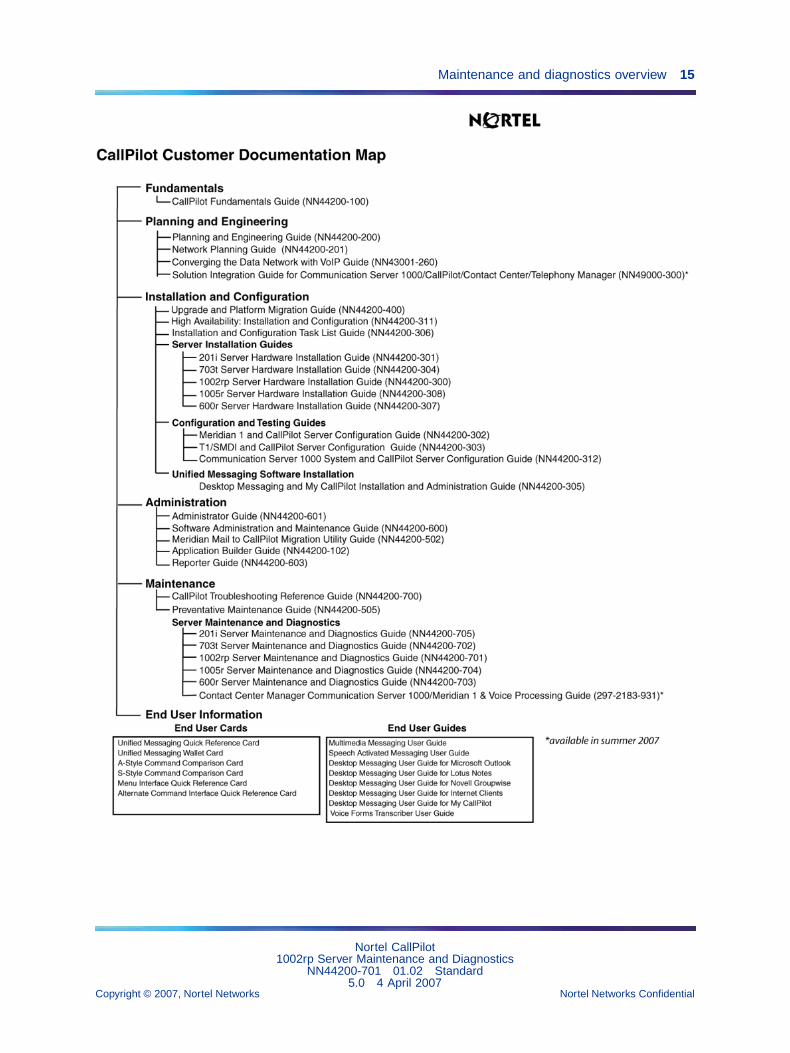
Reference documentsFor a list of all CallPilot documents, see the following CustomerDocumentation Map.
Nortel CallPilot1002rp Server Maintenance and Diagnostics
NN44200-701 01.02 Standard5.0 4 April 2007
Copyright © 2007, Nortel Networks Nortel Networks Confidential
.
Maintenance and diagnostics overview 15
Nortel CallPilot1002rp Server Maintenance and Diagnostics
NN44200-701 01.02 Standard5.0 4 April 2007
Copyright © 2007, Nortel Networks Nortel Networks Confidential
.

16 Chapter 2 About this guide
Nortel CallPilot1002rp Server Maintenance and Diagnostics
NN44200-701 01.02 Standard5.0 4 April 2007
Copyright © 2007, Nortel Networks Nortel Networks Confidential
.

17
Chapter 3Troubleshooting your CallPilot system
In this chapter"Startup diagnostics overview" (page 17)
"Basic hardware check" (page 17)
"Power-On Self-Test diagnostics" (page 18)
"Interpreting POST diagnostics" (page 19)
"Interpreting startup diagnostics from SCSI BIOS" (page 20)
"What to do when the server fails to boot into service" (page 21)
Startup diagnostics overviewThis section contains procedures for interpreting the startup diagnosticson the 1002rp server.
Types of startup diagnosticsThe following types of startup diagnostics are available on the server:
• basic hardware check (for example LEDs)
• Power-On Self-Test (POST) diagnostics
• SCSI controller diagnostics or RAID controller diagnostics
These diagnostics are available at initial system startup, or after any 1002rpserver reset.
Basic hardware checkThis section describes some basic checks that you can do when you startup the server.
Nortel CallPilot1002rp Server Maintenance and Diagnostics
NN44200-701 01.02 Standard5.0 4 April 2007
Copyright © 2007, Nortel Networks Nortel Networks Confidential
.

18 Chapter 3 Troubleshooting your CallPilot system
To run the startup test
Step Action
1 Power on the server and observe the front panel display.
Result: All LEDs on the panel illuminate for a few seconds. Thegreen power LED remains illuminated.
2 Observe the following server actions:
• Cooling fans on the front panel start up, and the red fault LEDnext to each fan extinguishes.
• Drives spin up, and the amber hard drive activity LEDs over thefront panel display extinguish, and then flash with activity.
• LEDs illuminate temporarily as the system checks the floppydrive, tape drive, and CD-ROM drive.
• The LED on each power supply lights up red as supply fans spinup and components charge. LEDs turn green when the attachedpower supply is fully operational.
3 Check the monitor for any error messages as the server counts RAMand completes a POST.
See "Power-On Self-Test diagnostics" (page 18) for more details onPOST.
—End—
Power-On Self-Test diagnosticsThe Power-On Self-Test (POST) is a system diagnostic program (stored inthe BIOS) that runs each time the 1002rp server is started. The function ofthe POST is to test system components and then display status messages.
To run the POST
Step Action
1 Power up the CallPilot server and monitor.
Result: After a few seconds, POST begins to run.
After the memory test, various screen prompts and messagesappear. The screen prompts may be accompanied by a single beep.
2 Observe the screen for any error messages and listen for POSTbeep codes. When POST completes, the server beeps once.
Nortel CallPilot1002rp Server Maintenance and Diagnostics
NN44200-701 01.02 Standard5.0 4 April 2007
Copyright © 2007, Nortel Networks Nortel Networks Confidential
.

Interpreting POST diagnostics 19
If the server halts before POST is finished, the server emits abeep code indicating that a fatal system error requires immediateattention. See "Interpreting POST diagnostics" (page 19) for details.
If POST can display a message on the monitor, the server emits twobeeps as the message appears.
Record the message that appears on the monitor and the beep codethat you hear. This information is useful if you need assistance fromyour technical support representative.
—End—
Interpreting POST diagnosticsThis section provides an explanation of the POST diagnostic codes.
POST beep codesIf an error occurs before video initialization, POST emits beep codes thatindicate errors in hardware, software, or firmware.
A beep code is a series of separate tones, each equal in length. Record thebeep code sequence before calling Nortel technical support.
ATTENTIONSome POST beep codes are fatal and may require that you replace the SingleBoard Card (SBC). See the table below for more information about beep codes.
POST beep codes
Beepcount Error message Description
1 Refresh Failure The memory refresh circuitry of the processorboard is faulty.
2 Parity Error A parity error was detected in the base memory(the first block of 64 kbytes) of the system.
3 Base 64KBMemory Failure
A memory failure occurred within the first 64kbytes of memory.
4 Timer NotOperational
A memory failure occurred within the first64 kbytes of memory, or Timer #1 on theprocessor board failed to function properly.
5 Processor Error The Central Processing Unit (CPU) on theprocessor board failed to function properly.
Nortel CallPilot1002rp Server Maintenance and Diagnostics
NN44200-701 01.02 Standard5.0 4 April 2007
Copyright © 2007, Nortel Networks Nortel Networks Confidential
.

20 Chapter 3 Troubleshooting your CallPilot system
Beepcount Error message Description
6 8042 - Gate A20Failure
The keyboard controller (8042) containsthe Gate A20 switch, which allows the CPUto operate in protected mode. This errormessage means that the BIOS cannot switchthe CPU into protected mode.
7 ProcessorExceptionInterrupt Error
The CPU on the processor board generatedan exception interrupt.
8 Display MemoryRead/Write Error
The system video adapter is either missing orits memory is faulty.
Note: This is not a fatal error.
9 ROM ChecksumError
The ROM checksum value does not match thevalue encoded in the BIOS.
10 CMOS ShutdownRegisterRead/Write Error
The shutdown register for the CMOS RAMfailed.
11 Cache MemoryBad: Do NoteEnable Cache
The cache memory test failed. Cache memoryis disabled.
Note: Do not press Ctrl+Alt+Shift<+> to enablecache memory.
Interpreting startup diagnostics from SCSI BIOSThe results from the SCSI controller diagnostics appear after the POSTresults.
Applicable cardsResults of the startup diagnostics appear only if you have the followingcards installed on your system:
• Adaptec SCSI controller
The adapter is integrated in the SBC and can be disabled.
• LSI Elite 1600 controller
Nortel CallPilot1002rp Server Maintenance and Diagnostics
NN44200-701 01.02 Standard5.0 4 April 2007
Copyright © 2007, Nortel Networks Nortel Networks Confidential
.

What to do when the server fails to boot into service 21
What to do when the server fails to boot into serviceThis section suggests tasks you can perform to determine why the serverfails the bootup cycle.
To determine why the server failed to boot to Windows
Step Action
1 Make a note of any diagnostic codes.
2 Try restarting the server by pressing the power button on the server.
3 During the boot sequence, view the diagnostic codes on the monitorfor failures.
4 Refer to the Troubleshooting Guide (NN44200-700) for othersuggestions. If you still cannot determine the cause of the startupfailure, call your Nortel technical support representative.
—End—
To determine why the server failed to boot into CallPilotIf the system-ready indicator indicates that the system is not booting intoCallPilot, follow these steps:
Step Action
1 Make a note of any diagnostic codes.
2 Try restarting the server by pressing the power button on the server.
3 During the boot sequence, view the diagnostic codes on the monitorfor failures.
4 View the event logs. For instructions, see "Viewing event logs" (page23).
5 Refer to the Troubleshooting Guide (NN44200-700) for othersuggestions. If you still cannot determine the cause of the startupfailure, call your Nortel technical support representative.
—End—
Nortel CallPilot1002rp Server Maintenance and Diagnostics
NN44200-701 01.02 Standard5.0 4 April 2007
Copyright © 2007, Nortel Networks Nortel Networks Confidential
.

22 Chapter 3 Troubleshooting your CallPilot system
Nortel CallPilot1002rp Server Maintenance and Diagnostics
NN44200-701 01.02 Standard5.0 4 April 2007
Copyright © 2007, Nortel Networks Nortel Networks Confidential
.
23
Chapter 4Using Windows online diagnostic tools
In this chapter"Overview" (page 23)
"Viewing event logs" (page 23)
"Using TCP/IP diagnostic tools" (page 27)
"Using the chkdsk utility" (page 34)
OverviewThis section describes how to access the run-time online diagnostic toolsprovided by the Windows server software. Use the following tools when aserious problem prevents the use of the CallPilot diagnostic tools that areavailable in CallPilot Manager.
• Windows Event Viewer
• TCP/IP diagnostics
• chkdsk utility
CAUTIONRisk of software corruptionDo not run any utilities that are not documented in this guide.
Viewing event logsWhen the server startup cycle is complete, and if the CallPilot server hasbeen configured, messages in dialog boxes on the monitor indicate thatCallPilot is ready to accept calls.
Nortel CallPilot1002rp Server Maintenance and Diagnostics
NN44200-701 01.02 Standard5.0 4 April 2007
Copyright © 2007, Nortel Networks Nortel Networks Confidential
.

24 Chapter 4 Using Windows online diagnostic tools
If one or more messages appear on the monitor, the message may containinformation about an event, or a fault may have occurred. To determinewhat happened, you can use the following diagnostic tools:
• Windows Event Viewer on the 1002rp server
• CallPilot Event Browser or Alarm Monitor in CallPilot Manager
Note: The Event Browser and Alarm Monitor include online Help forevents, which may help you to resolve the problem. If you cannot logon to the CallPilot system using a web browser due to server problems,then use the Windows Event Viewer.
Types of event logsThree types of event logs are available from the Windows Event Viewer, asfollows:
Log type Description
System Logs events by Windows components, including RRASor other Windows services.
Security Logs security events, such as logons, logoffs, andillegal access. This option is available only to userswith Administrative access.
Applications Logs events by application, such as database fileerrors.
To use the operating system Event Viewer
Step Action
1 Click Start → Programs → Administrative Tools → Event Viewer.
Result: The Event Viewer window appears.
Nortel CallPilot1002rp Server Maintenance and Diagnostics
NN44200-701 01.02 Standard5.0 4 April 2007
Copyright © 2007, Nortel Networks Nortel Networks Confidential
.

Viewing event logs 25
Event Viewer
2 To view a log, click the name of the log in the left pane of the window.
The following illustration shows an example of the Application Log.
Application log
The following illustration shows an example of a System log.
Nortel CallPilot1002rp Server Maintenance and Diagnostics
NN44200-701 01.02 Standard5.0 4 April 2007
Copyright © 2007, Nortel Networks Nortel Networks Confidential
.

26 Chapter 4 Using Windows online diagnostic tools
System log
Note: The Security log, which is available only to administrators,is not shown.
3 Look for error codes that have occurred since the last startup. Errorcodes are flagged with the following symbols.
Note: Each error is date- and time-stamped.
indicates major or critical errors
indicates minor errors
indicates information
4 To determine the cause of the error, select and then double-clickthe error.
Result: A description of the error appears in an Event detail dialogbox. Use the description to help determine how to resolve errors.
Note: If the error persists or the error description does notsuggest a solution, contact your Nortel support representative.
Nortel CallPilot1002rp Server Maintenance and Diagnostics
NN44200-701 01.02 Standard5.0 4 April 2007
Copyright © 2007, Nortel Networks Nortel Networks Confidential
.

Using TCP/IP diagnostic tools 27
5 Click Close.
Result: The event log reappears.
6 Click Log → Exit.
Result: The Event Viewer closes.
—End—
Using TCP/IP diagnostic toolsThis section describes the following TCP/IP diagnostic tools which areavailable for the network adapter:
• ipconfig
• ping
• tracert
• arp
• nbtstat
• netstat
These utilities help you to verify network connectivity, test the networkinterface, and isolate any configuration problems.
The ipconfig commandThe ipconfig command displays IP configuration information.
ipconfig defaultIf you run the command without flags, it displays the IP address, subnetmask, and default gateway for each adapter bound to TCP/IP.
ipconfig command syntaxThe ipconfig command uses the following syntax:
ipconfig /[ ]
The following flags are available for the ipconfig command.
ipconfig command extensions
Flag Description
/? Displays Help information.
/all Displays full configuration information.
/release Releases the IP address for the specified adapter.
/renew Renews the IP address for the specified adapter.
Nortel CallPilot1002rp Server Maintenance and Diagnostics
NN44200-701 01.02 Standard5.0 4 April 2007
Copyright © 2007, Nortel Networks Nortel Networks Confidential
.

28 Chapter 4 Using Windows online diagnostic tools
To run the ipconfig command from Windows
Step Action
1 Click Start → Programs → Accessories → Command Prompt.
Result: The Command Prompt window appears.
2 At the Command prompt, type ipconfig <parameters>.
Example: ipconfig /all
3 Press Enter.
Result: The system runs the ipconfig utility.
4 Type Exit to exit the Command Prompt window and return toWindows.
—End—
The ping commandThe ping command sends an echo request to a specified host. Use thiscommand to verify network connectivity to the remote device.
Ping command syntaxThe ping command uses the following syntax:
ping [-t] [-a] [-n count] [-l size] [-f] [-i TTL][-v TOS] [-r count] [-s count][[-j host-list] | [-k host-list]][-w timeout] destination-list
ping command extensions
Parameter Description
-t Pings the specified host until interrupted.
-a Resolves addresses to host names.
-n count Specifies the number of echo requests to send.
-l size Sends buffer size.
-f Sets Don’t Fragment flag in packet.
-i TTL Specifies the Time To Live
-v TOS Specifies the Type Of Service
-r count Specifies the number of Record route for count hops
-s count Specifies the number of Time stamp for count hops
-j host-list Specifies the Loose source route along host list
Nortel CallPilot1002rp Server Maintenance and Diagnostics
NN44200-701 01.02 Standard5.0 4 April 2007
Copyright © 2007, Nortel Networks Nortel Networks Confidential
.

Using TCP/IP diagnostic tools 29
Parameter Description
-k host-list Specifies the Strict source route along host list
-w timeout Specifies the Timeout in milliseconds to wait for eachreply
To run the ping command from Windows
Step Action
1 Click Start → Programs → Accessories → Command Prompt.
Result: The Command Prompt window appears.
2 At the Command prompt, type ping <destination IPaddress> (for example, ping 200.286.32.0), or ping <computername>.
3 Press Enter.
Result: The system displays the ping results.
4 Type Exit to exit the Command Prompt window and return toWindows.
—End—
The tracert commandThis utility determines the route taken to a destination.
How tracert worksThe tracert utility follows several steps to complete its task:
• Tracert sends Internet Control Message Protocol (ICMP) echo packetswith varying Time-To-Live (TTL) values to the destination.
• Each router along the path must decrement the TTL on a packet by atleast 1 before forwarding it, so the TTL is effectively a hop count.
• When the TTL on a packet reaches 0, the router sends back an ICMPTime Exceeded message to the source system.
• Tracert determines the route by sending the first echo packet with a TTLof 1, and incrementing the TTL by 1 on each subsequent transmissionuntil the target responds, or the maximum TTL is reached.
• Tracert then examines the ICMP Time Exceeded messages sent backby intermediate routers.
Nortel CallPilot1002rp Server Maintenance and Diagnostics
NN44200-701 01.02 Standard5.0 4 April 2007
Copyright © 2007, Nortel Networks Nortel Networks Confidential
.

30 Chapter 4 Using Windows online diagnostic tools
Tracert syntaxThe tracert command uses the following syntax:
tracert [-d] [-h maximum_hops] [-j host_list][-w timeout] [target_name]
Tracert parametersthe following table shows the tracert parameters.
Tracert parameters
Parameter Description
-d Specifies not to resolve addresses to hostnames.
-h maximum_hops Specifies the maximum number of hops to search forthe target.
-j host-list Specifies a loose source route along the host list.
-w timeout Waits the number of milliseconds specified by thetimeout for each reply.
target_name Specifies the name of the target host.
To run the tracert command from Windows
Step Action
1 Click Start → Programs → Accessories → Command Prompt.
Result: The Command Prompt window appears.
2 At the Command prompt, type the following command:
tracert [-d] [-h maximum_hops] [-j host_list] [-wtimeout] [target_name]
Example: tracert 200.286.0.32
3 Press Enter.
Result: The system runs the tracert utility.
4 Type Exit to exit the Command Prompt window and return toWindows.
—End—
The arp commandThe arp command displays and modifies the IP-to-physical addresstranslation tables used by Address Resolution Protocol (ARP).
Nortel CallPilot1002rp Server Maintenance and Diagnostics
NN44200-701 01.02 Standard5.0 4 April 2007
Copyright © 2007, Nortel Networks Nortel Networks Confidential
.

Using TCP/IP diagnostic tools 31
ARP command syntaxThe ARP command uses the following syntax:
arp -s inet_addr eth_addr [if_addr]
arp -d inet_addr [if_addr]
arp -a [inet_addr] [-N if_addr]
ARP command parameters
ARP command parameters
Parameter Description
-a Displays current arp entries by interrogating the current protocoldata. If inet_addr is specified, the IP and physical addresses foronly the specified computer appear. If more than one networkinterface uses arp, entries for each arp table appear.
-g Same as -a.
inet_addr Specifies an Internet address.
if_addr Specifies the Internet address of the interface where theaddress translation table should be modified. If not present, thefirst applicable interface is used.
eth_addr Specifies a physical address.
-N if_addr Displays the arp entries for the network interface specified byif_addr.
-d Deletes the host specified by inet_addr.
-s Adds the host and associates the Internet address inet_addrwith the physical address eth_addr. The physical address isgiven as six hexadecimal bytes separated by hyphens. Theentry is permanent.
To run the arp command from Windows
Step Action
1 Click Start → Programs → Accessories → Command Prompt.
Result: The Command Prompt window appears.
2 At the Command prompt, type arp with the required parameters (forexample, arp -g 200.286.0.32).
3 Press Enter.
Result: The system runs the arp command.
4 Type Exit to exit the Command Prompt window and return toWindows.
Nortel CallPilot1002rp Server Maintenance and Diagnostics
NN44200-701 01.02 Standard5.0 4 April 2007
Copyright © 2007, Nortel Networks Nortel Networks Confidential
.

32 Chapter 4 Using Windows online diagnostic tools
—End—
The nbtstat commandThe nbtstat command displays protocol statistics and current TCP/IPconnections using NBT.
Nbtstat command syntaxThe nbtstat command uses the following syntax:
nbtstat [-a remotename] [-A IP address] [-c] [-n][-R] [-r] [-S] [-s] [interval]
nbstat command parameters
nbstat command parameters
Parameter Description
-a remotename Lists the remote computer name table using its name.
-A IP address Lists the remote computer name table using its IPaddress.
-c Lists the contents of the NetBIOS name cache givingthe IP address of each name.
-n Lists local NetBIOS names. Registered indicates thatthe name is registered by broadcast (Bnode) or WINS(other node types).
-R Reloads the LMHOSTS file after purging all namesfrom the NetBIOS name cache.
-r Lists name resolution statistics for Windows networkingname resolution. On a Windows computer configuredto use WINS, this option returns the number of namesresolved and registered through broadcast or throughWINS.
-S Displays both client and server sessions, listing theremote hosts by IP address only.
-s Displays both client and server sessions and attemptsto convert the remote host IP address to a name usingthe HOSTS file.
interval Displays selected statistics, pausing interval secondsbetween each display. Press Ctrl+C to stop displayingstatistics. Without this parameter, nbtstat prints thecurrent configuration information once.
To run the nbtstat command from Windows
Nortel CallPilot1002rp Server Maintenance and Diagnostics
NN44200-701 01.02 Standard5.0 4 April 2007
Copyright © 2007, Nortel Networks Nortel Networks Confidential
.

Using TCP/IP diagnostic tools 33
Step Action
1 Click Start → Programs → Accessories → Command Prompt.
Result: The Command Prompt window appears.
2 At the Command prompt, type nbtstat with the requiredparameters.
3 Press Enter.
Result: The system runs the nbtstat utility.
4 Type Exit to exit the Command Prompt window and return toWindows.
—End—
The netstat commandThe netstat command displays current TCP/IP network connections andprotocol statistics.
Netstat command syntaxThe netstat command uses the following syntax:
netstat [-a] [-e] [-n] [-s] [-p proto] [-r] [interval]
netstat command parameters
netstat command parameters
Parameter Description
-a Displays all connections and listening ports.
-e Displays Ethernet statistics. This can be combined with the-s option.
-n Displays addresses and port numbers in numeric form.
-s Displays statistics for each protocol.
-p proto Shows connections for the protocol specified by proto. Protocan be tcp or udp. If used with the -s option, proto can be tcp,udp, or ip.
-r Displays the contents of the routing table.
interval Redisplays selected statistics, pausing between each display.Press Ctrl+C to stop redisplaying.
To run the netstat command from Windows
Nortel CallPilot1002rp Server Maintenance and Diagnostics
NN44200-701 01.02 Standard5.0 4 April 2007
Copyright © 2007, Nortel Networks Nortel Networks Confidential
.

34 Chapter 4 Using Windows online diagnostic tools
Step Action
1 Click Start → Programs → Accessories → Command Prompt.
Result: The Command Prompt window appears.
2 At the Command prompt, type netstat with the requiredparameters.
3 Press Enter.
Result: The system runs the netstat utility.
4 Type Exit to exit the Command Prompt window and return toWindows.
—End—
Using the chkdsk utilityThe chkdsk utility checks a specified disk on the server and displays astatus report. You can run the utility on drives C, D, E, or F. It is an onlineutility, but it reduces system performance while it is running.
The chkdsk utility checks for errors at the Windows file system level. CallPilotcan be affected by errors at both the Windows and CallPilot file systemlevels. The chkdsk utility will not detect CallPilot file system level errors.
Note: A version of this utility, called autocheck, automatically runsduring Windows startup. Output from this utility appears on the bluestartup screen.
Chkdsk utility syntaxThe chkdsk utility uses the following syntax:
chkdsk [drive:][path]filename] [/F] [/V] [/R]
Chksdsk utility parameters
Chksdsk utility parameters
Parameter Description
drive: Drive letter of the drive that you want to check.
filename Names of files to check for fragmentation.
/F Optional parameter to fix errors on the disk.
Nortel CallPilot1002rp Server Maintenance and Diagnostics
NN44200-701 01.02 Standard5.0 4 April 2007
Copyright © 2007, Nortel Networks Nortel Networks Confidential
.

Using the chkdsk utility 35
Parameter Description
/V Optional parameter to display the full pathname ofevery file on the disk.
/R Optional parameter to locate bad sectors and torecover readable information.
To run the chkdsk utility from Windows
Step Action
1 Click Start → Programs → Accessories → Command Prompt.
Result: The Command Prompt window appears.
2 At the Command prompt, type chkdsk <drive letter:> (forexample, chkdsk c:).
3 Press Enter.
Result: The system runs the chkdsk utility.
4 Type Exit to exit the Command Prompt window and return toWindows.
—End—
Nortel CallPilot1002rp Server Maintenance and Diagnostics
NN44200-701 01.02 Standard5.0 4 April 2007
Copyright © 2007, Nortel Networks Nortel Networks Confidential
.

36 Chapter 4 Using Windows online diagnostic tools
Nortel CallPilot1002rp Server Maintenance and Diagnostics
NN44200-701 01.02 Standard5.0 4 April 2007
Copyright © 2007, Nortel Networks Nortel Networks Confidential
.

37
Chapter 5Using serial port diagnostic tools
In this chapter"Overview" (page 37)
"Shutting down services" (page 37)
"Conducting TSTSERIO tests" (page 40)
"Conducting TSTSERIO tests with the loopback plug" (page 42)
"Restarting services" (page 43)
OverviewYou may want to test the serial ports when remote access does not work.
This chapter describes how to run serial port diagnostics on the CallPilotserver using the TSTSERIO command. Direct the TSTSERIO commandto serial ports on the server after services on these ports have been shutdown manually, as described in this chapter.
Shutting down servicesThis section describes how to shut down a service using a specific serialport. Use the following procedures before you invoke the TSTSERIO localloopback tests.
CAUTIONRisk of communications lossBy stopping the services on COM1 or COM2, you lose the supportaccess feature.
Nortel CallPilot1002rp Server Maintenance and Diagnostics
NN44200-701 01.02 Standard5.0 4 April 2007
Copyright © 2007, Nortel Networks Nortel Networks Confidential
.

38 Chapter 5 Using serial port diagnostic tools
CAUTIONRisk of stopping call processingBy stopping the services on COM2, you stop call processing onCallPilot.
Services to stop for COM1 testing
• Routing and Remote Access Service
Services to stop for COM2 testing
• CallPilot SLEE Service
• CallPilot MWI Service
• CallPilot Access Protocol Emulator
• CallPilot Blue Call Router
• CallPilot Call Channel Router
• CallPilot Time Service
• Routing and Remote Access Service
Net Stop commandUse the Net Stop command to stop a specified service on a serial port.
Net stop command syntaxThe Net Stop command uses the following syntax:
net stop <service_name>
ATTENTIONYou must restart the services that you shut down through the Net Start commandafter you run the diagnostic. For details, see "Restarting services" (page 43).
To invoke the Net Stop command from Windows
Step Action
1 Click Start → Programs → Accessories → Command Prompt.
Result: The Command Prompt window appears.
2 At the Command prompt, type net stop "service_name", andthen press Enter.
Example: Type net stop "Remote Access Server", and thenpress Enter.
Note: The quotation marks are required, as in the exampleabove.
Nortel CallPilot1002rp Server Maintenance and Diagnostics
NN44200-701 01.02 Standard5.0 4 April 2007
Copyright © 2007, Nortel Networks Nortel Networks Confidential
.

Shutting down services 39
Result: The system runs the Net Stop command utility.
3 Type Exit, and then press Enter to exit the Command Promptwindow.
—End—
Service Control (SC) commandUse the Service Control command to stop a specified service on a serialport.
Service Control command syntaxThe Service Control command uses the following syntax:
sc <service_name>
ATTENTIONYou must restart the services that you shut down through the Service Controlcommand after you run the diagnostic. For details, see "Restarting services"(page 43).
To invoke the Service Control command from Windows
Step Action
1 Click Start → Programs → Accessories → Command Prompt.
Result: The Command Prompt window appears.
2 At the Command prompt, type sc stop "service_name", andthen press Enter.
Example: Type sc stop "Remote Access Server", and thenpress Enter.
Note: The quotation marks are required, as in the exampleabove.
Result: The system runs the Service Control command utility.
3 Type Exit, and then press Enter to exit the Command Promptwindow.
—End—
Nortel CallPilot1002rp Server Maintenance and Diagnostics
NN44200-701 01.02 Standard5.0 4 April 2007
Copyright © 2007, Nortel Networks Nortel Networks Confidential
.

40 Chapter 5 Using serial port diagnostic tools
Conducting TSTSERIO testsThe TSTSERIO command performs local loopback tests of the serialcommunication ports from the server run-time environment.
Note: Before conducting these tests, shut down the appropriateservices. See "Shutting down services" (page 37).
CAUTIONRisk of communications lossBy stopping the services on COM1 or COM2, you lose the supportaccess feature.
CAUTIONRisk of stopping call processingBy stopping the services on COM2, you stop call processing onCallPilot.
TSTSERIO command syntaxThe syntax for the TSTSERIO command is as follows:
TSTSERIO [/?] /P:comport [/S:subtstname] [/L:loops]
TSTSERIO command parameters
TSTSERIO command parameters
Flag Requirement Description
? n/a Displays Help.
/P:comport Required Specifies the symbolicport name assigned tothe port you want to test.
/S:subtstname Optional Specifies a TSTSERIOsubtest. See the followingtable for a description ofthe available subtests.
/L:loops Optional Specifies the number oftimes (up to a maximumof 65 535) to executethe requested test. Thedefault number of tests is1. A value of 0 infinitelyloops until you enterCtrl+C.
Nortel CallPilot1002rp Server Maintenance and Diagnostics
NN44200-701 01.02 Standard5.0 4 April 2007
Copyright © 2007, Nortel Networks Nortel Networks Confidential
.

Conducting TSTSERIO tests 41
TSTSERIO internal loopback diagnostic subtestsThe following internal loopback subtests are available for the TSTSERIOcommand. For each of these tests, the communications resource mustbe available.
TSTSERIO internal loopback subtests
Subtest name Description
idata Internal data bus loopback
imsr Internal modem status register
baud Internal data bus loopback at various baud rates
word Test 5-, 6-, 7-, and 8-bit data lengths
stop Test 1, 1.5, and 2 stop bits
pari Test odd/even parity
fifo Test that device can operate in fifo mode
To invoke the TSTSERIO /P command from Windows
Step Action
1 Click Start → Programs → Accessories → Command Prompt.
Result: The Command Prompt window appears.
2 At the Command prompt, type tstserio with the requiredparameters, and then press Enter.
For example, type TSTSERIO /P com1 or TSTSERIO /P com2, and then press Enter.
3 Type Exit, and then press Enter to exit the Command Promptwindow.
—End—
Nortel CallPilot1002rp Server Maintenance and Diagnostics
NN44200-701 01.02 Standard5.0 4 April 2007
Copyright © 2007, Nortel Networks Nortel Networks Confidential
.

42 Chapter 5 Using serial port diagnostic tools
TSTSERIO external loopback plug subtestsThe following external loopback subtests are available for the TSTSERIOcommand. For each of these tests, an external loopback connector mustbe used. For more information, see "Conducting TSTSERIO tests withthe loopback plug" (page 42)
TSTSERIO external loopback plug subtests.
Subtestname
Description
edata External data bus loopback. This test requires an externalloopback connector.
emsr External modem status register. This test requires an externalloopback connector.
eint Test ability of device to generate interrupts. This test requiresan external loopback connector.
To invoke the TSTSERIO /S command from Windows
Step Action
1 Click Start → Programs → Accessories → Command Prompt.
Result:The Command Prompt window appears.
2 At the Command prompt, type tstserio with the requiredparameters, and then press Enter.
For example, type TSTSERIO /P com1 /S extr, and then pressEnter.
3 Type Exit, and then press Enter to exit the Command Promptwindow.
—End—
Conducting TSTSERIO tests with the loopback plugThe TSTSERIO command requires an external loopback connector plug forits edata, emsr, and eint subtests.
9-pin connector plugThe standard serial loopback connector is a female 9-pin D-sub connector.This connector has the following pins wired together:
• CTS (pin 8) wired to RTS (pin 7)
• SIN (pin 2) wired to SOUT (pin 3)
• DTR (pin 4) wired to DSR (pin 6)
Nortel CallPilot1002rp Server Maintenance and Diagnostics
NN44200-701 01.02 Standard5.0 4 April 2007
Copyright © 2007, Nortel Networks Nortel Networks Confidential
.
Restarting services 43
Once the plug is installed on the serial port, TSTSERIO can be invokedaccording to the procedure outlined in the previous section.
Restarting servicesThis section describes how to restart the services for COM1 or COM2 afterinvoking the TSTSERIO local loopback tests.
Services to restart after COM1 testing
• Routing and Remote Access Service
Services to restart after COM2 testing
• CallPilot SLEE Service
• CallPilot MWI Service
• CallPilot Access Protocol Emulator
• CallPilot Blue Call Router
• CallPilot Call Channel Router
• CallPilot Time Service
• Routing and Remote Access Service
Net Start commandUse the Net Start command to restart a specified service on a serial port.The syntax for the Net Start command is as follows:
net start <service name>
To invoke the Net Start command from Windows
Step Action
1 Click Start → Programs → Accessories → Command Prompt.
Result: The Command Prompt window appears.
2 At the Command prompt, type net start "service_name",and then press Enter.
For example, type net start "Remote Access Server", andthen press Enter.
Note: The quotation marks are required, as in the exampleabove.
3 Type Exit, and then press Enter to exit the Command Promptwindow.
Nortel CallPilot1002rp Server Maintenance and Diagnostics
NN44200-701 01.02 Standard5.0 4 April 2007
Copyright © 2007, Nortel Networks Nortel Networks Confidential
.

44 Chapter 5 Using serial port diagnostic tools
—End—
Service Control Start commandUse the Service Control Start command to restart a specified service on aserial port. The syntax for the Service Control Start command is as follows:
sc <service name>
To invoke the Service Control Start command from Windows
Step Action
1 Click Start → Programs → Accessories → Command Prompt.
Result: The Command Prompt window appears.
2 At the Command prompt, type sc start "service_name", andthen press Enter.
For example, type sc start "Remote Access Server", andthen press Enter.
Note: The quotation marks are required, as in the exampleabove.
3 Type Exit, and then press Enter to exit the Command Promptwindow.
—End—
Nortel CallPilot1002rp Server Maintenance and Diagnostics
NN44200-701 01.02 Standard5.0 4 April 2007
Copyright © 2007, Nortel Networks Nortel Networks Confidential
.

45
Chapter 6Using CallPilot Manager to monitorhardware
In this chapter"Understanding fault management" (page 45)
"Alarm Monitor" (page 47)
"Event Browser" (page 48)
"Channel and Multimedia Monitors" (page 50)
"The Maintenance screen" (page 50)
"Viewing component states" (page 53)
"Starting and stopping components" (page 55)
"Running integrated diagnostics" (page 58)
"Viewing the last diagnostic results" (page 60)
"Working with the Multimedia Monitor" (page 61)
"Working with the Channel Monitor" (page 63)
Understanding fault managementFault management is a term that describes how the CallPilot server detectsand notifies you of potential or real hardware problems (faults). The serverprocesses events to detect hardware problems and raises alarms to notifyyou when these problems occur.
Nortel CallPilot1002rp Server Maintenance and Diagnostics
NN44200-701 01.02 Standard5.0 4 April 2007
Copyright © 2007, Nortel Networks Nortel Networks Confidential
.

46 Chapter 6 Using CallPilot Manager to monitor hardware
Event processingAn event is any change in system configuration or operational state. Anevent is also any action taken by the system that requires user notification.Events can be as insignificant as a user logon attempt or as serious as afaulty MPB96 card switching to disabled status.
All events are reported to the fault management server, a subsystem withinthe CallPilot server. The fault management server enables the CallPilotserver to listen and respond to its clients. The interaction is called eventprocessing and is the means by which the server detects hardware faults.
Alarm notificationAlarms are warnings generated by events. Alarms communicate the sameinformation as events. However, alarms are reported in the Alarm Monitorinstead of the Event Browser, and are managed differently than events.
When an alarm appears in the Alarm Monitor, you must investigate theproblem, isolate it, and then fix the cause of the problem. When you fix theproblem, the alarm is cleared from the Alarm Monitor.
Component dependenciesThe status of some components are dependent on the operational statusof other components. If a component fails or is stopped, the dependentcomponents go out of service.
Note: Based on the CallPilot server type, and the type of switchconnected to CallPilot, some of these components may not appear onyour system.
Component Dependent components
Media Bus All MPBs, all multimedia channels, and all call channels.
MPB board All multimedia and call channels associated with the MPBboard.
Time Switch All multimedia and call channels associated with the sameMPB as the time switch.
MPB96 All multimedia channels on the MPB96 card.
DS30X All DS30X channels associated with the DS30X link.
T1 board Telephony Interface. All DS0 (zero) channels associated withthe telephony interface.
Detecting hardware problemsTypically, you first become aware of a hardware problem when an alarm israised. All hardware faults produce an alarm (or series of alarms, dependingon the problem) in the Alarm Monitor.
Nortel CallPilot1002rp Server Maintenance and Diagnostics
NN44200-701 01.02 Standard5.0 4 April 2007
Copyright © 2007, Nortel Networks Nortel Networks Confidential
.

Alarm Monitor 47
Other indications of a hardware problem include the following:
• user complaints
• call processing difficulties, such as busy signals, static, dropped calls,connection problems, and cross talk (hearing other conversations)
• system administrator logon difficulties
• alert icons on the Maintenance screen
Alarm MonitorUse the Alarm Monitor to investigate one or more raised alarms.
About alarmsAlarms are warnings generated by events. Alarms communicate the sameinformation as events. However, alarms are reported in the Alarm Monitorinstead of the Event Browser, and are managed differently than events:
• Alarms appear in the Alarm Monitor only for Minor, Major, and Criticalevents (not Information events). All events can be reported in the EventBrowser (depending on filtering criteria defined in the Event Browser).
• The first time an event occurs, it generates an alarm that appears inthe Alarm Monitor. If the same event continues to occur, a new alarmis not generated. Instead, the time and date assigned to the originalgenerated alarm is updated.
• Alarms can be cleared from the Alarm Monitor, but the event thatgenerated the alarm is not cleared from the event log or the EventBrowser.
Each alarm in the Alarm Monitor has Help text that often provides a solutionto the problem. If the solution is not apparent, use the Event Browser or theMaintenance screen to further investigate the problem.
To investigate using the Alarm Monitor
Step Action
1 Run CallPilot Manager and log in.
2 In CallPilot Manager, click System→Alarm Monitor.
Result: The Alarm Monitor screen appears.
Nortel CallPilot1002rp Server Maintenance and Diagnostics
NN44200-701 01.02 Standard5.0 4 April 2007
Copyright © 2007, Nortel Networks Nortel Networks Confidential
.

48 Chapter 6 Using CallPilot Manager to monitor hardware
Alarm monitor screen
3 Click the Event Code for the first Critical or Major alarm.
Result: A description of the event appears in a new web browserwindow.
4 Review the description and recovery action.
5 Repeat steps 3 and 4 for more alarms, if necessary.
6 If the solution to the problem is not apparent, obtain the return codeof the first event and continue the investigation by using the EventBrowser (see "Event Browser" (page 48)).
—End—
Event BrowserUse the Event Browser to investigate a series of events that occurredaround the time an alarm was raised. The event listing can help youdetermine the root cause of a problem.
Nortel CallPilot1002rp Server Maintenance and Diagnostics
NN44200-701 01.02 Standard5.0 4 April 2007
Copyright © 2007, Nortel Networks Nortel Networks Confidential
.

Event Browser 49
About eventsThe Event Browser displays events that have been recorded in the serverlog. Each event identifies the time the event occurred, the object thatgenerated the event, and the cause of the event.
Events are classified as Information, Minor, Major, or Critical. By default, theEvent Browser displays only the latest 100 critical events.
To investigate using the Event Browser
Step Action
1 Run CallPilot Manager and log in.
2 In CallPilot Manager, click System→Event Browser.
Result: The Event Browser screen appears.
Event browser screen
3 Click an event that appears to be related to the problem, or an eventthat occurred near the time the alarm was raised.
Result: A description of the event appears in a new web browserwindow.
Nortel CallPilot1002rp Server Maintenance and Diagnostics
NN44200-701 01.02 Standard5.0 4 April 2007
Copyright © 2007, Nortel Networks Nortel Networks Confidential
.

50 Chapter 6 Using CallPilot Manager to monitor hardware
4 View the description and recovery action.
5 Repeat steps 3 and 4 for more events, if necessary.
6 If the solution to the problem is not apparent, contact your Norteltechnical support representative.
—End—
Note: For information on how to use the Event Browser refer to theCallPilot Manager online Help.
Channel and Multimedia MonitorsThe Channel Monitor shows the status of call channels. The call channelsare the connections between the server and the switch that carry the callsignals to CallPilot.
The Multimedia Monitor shows the status of multimedia channels. Themultimedia channels are the DSP ports that process the calls. They are thevoice, fax, and speech recognition channels.
Disabling call channelsIf you must take the CallPilot system out of service to perform softwareor hardware maintenance, Nortel recommends that you disable all callchannels first. There are two ways to disable the call channels:
• Courtesy stop the channels (preferred method).
When you courtesy stop call channels, CallPilot waits until the channelsare no longer active before disabling them, instead of suddenlyterminating active calls.
• Stop the channels.
When you stop channels, you suddenly disable them and terminateall active calls.
The Maintenance screenUse the Maintenance screen in CallPilot Manager to do the following:
• Obtain general information about components.
• View component states.
• Start and stop components.
• Run integrated diagnostic tests.
• View the results of the last diagnostic test run against a component.
Nortel CallPilot1002rp Server Maintenance and Diagnostics
NN44200-701 01.02 Standard5.0 4 April 2007
Copyright © 2007, Nortel Networks Nortel Networks Confidential
.

The Maintenance screen 51
What the Maintenance screen providesThe Maintenance screen identifies the server platform and switchconnectivity type. It also provides a tree that, when expanded, lists thephysical and logical hardware components down the left side of the screen.To list the server hardware components, click the plus sign (+) at the top ofthe tree. To list the subcomponents for each component, click the plus sign(+) beside the component.
Note: The components that are listed on the Maintenance screen arebased on the CallPilot server type and the switch that is connected toCallPilot. The examples in this chapter are for illustration purposes andmay not appear exactly the same on your system.
"Partially expanded tree for 1002rp" (page 51) shows a partially expandedtree for the 1002rp server.
Partially expanded tree for 1002rp
Nortel CallPilot1002rp Server Maintenance and Diagnostics
NN44200-701 01.02 Standard5.0 4 April 2007
Copyright © 2007, Nortel Networks Nortel Networks Confidential
.

52 Chapter 6 Using CallPilot Manager to monitor hardware
When you click a component, the screen refreshes to show the detailsabout that component. Details are divided into the sections describedin the following table.
Component sections
Section Description
General This section shows general technical information aboutthe selected component. This typically includes thefollowing details:
• the name, class, type, series, or version of acomponent
• various capabilities of a component (for example,whether a component is removable)
Note: This section does not appear for all components.
Maintenance This section shows the state of the selectedcomponent. Use this section to start and stop acomponent before running a diagnostic test.
This section appears only for components on which youare allowed to perform maintenance administration.
For more information about working with componentstates, see the following sections:
• "Viewing component states" (page 53)
• "Starting and stopping components" (page 55)
Diagnostics Use the Diagnostics section to run one or morediagnostic tests, or to view the results of the lastdiagnostic tests that were run on the selectedcomponent.
This section appears only for components on whichyou are allowed to run diagnostics.
For more information about running diagnostics, seethe following sections:
Nortel CallPilot1002rp Server Maintenance and Diagnostics
NN44200-701 01.02 Standard5.0 4 April 2007
Copyright © 2007, Nortel Networks Nortel Networks Confidential
.

Viewing component states 53
Section Description
• "Running integrated diagnostics" (page 58)
• "Viewing the last diagnostic results" (page 60)
Maintenance activities for each componentThe following table identifies the maintenance activities you can perform foreach component that is listed in the component tree.
Maintenance activities
ComponentStart,stop?
Courtesystop?
Diagnosticsavailable? Replaceable?
Media Bus Yes No Yes No
MPB96 board Yes No Yes Yes
Time Switch No No No No
MPCs (embedded on MPBboards)
Yes No Yes embedded:No
Multimedia channels Yes Yes Yes No
Call channels Yes Yes No No
DS30X link Yes No No No
Note: The MGate card and DS30X cable are replaceable. If you are having problems with theDS30X link, determine if either one or both of these items are causing the problem and need to bereplaced.
Viewing component statesView a component state to determine the general condition of thecomponent, including whether the component is disabled or off duty. Thecomponent state is shown in the Maintenance section of the Maintenancescreen.
Nortel CallPilot1002rp Server Maintenance and Diagnostics
NN44200-701 01.02 Standard5.0 4 April 2007
Copyright © 2007, Nortel Networks Nortel Networks Confidential
.

54 Chapter 6 Using CallPilot Manager to monitor hardware
Component statesYou can determine the state of a component by looking at the State boxin the Maintenance section.
State Description
Active The component is working and currently involved inprocessing a call.
Disabled The diagnostic failed.
Idle The component is working but not currently involvedin processing a call.
InTest A diagnostic is running on the resource or device.
Loading The component has been started, which takes it outof the Off Duty state.
This state occurs quickly and is immediately followedby Idle.
Local (Red) Alarm A Receive Loss of Synchronization error occurred onincoming data over a T1 link and lasted more than 2.5seconds. This condition will exist until synchronizationis recovered and remains recovered for 12 seconds.
No resources The hardware required for the component to operate isnot installed or is not operating properly.
Not Configured The device is not configured in CallPilot.
For example, a DSP is not being used because it wasnot allocated in the Configuration Wizard.
Off Duty The component has been stopped.
Remote Off Duty The component has been taken out of service at theswitch.
Remote (Yellow)Alarm
A red alarm exists at the receiving device. This alarmis sent by the receiving T1 device to CallPilot, and itremains in effect until the red alarm is cleared at thereceiving device.
Shutting Down The component is in the process of stopping.
This state occurs quickly and is immediately followedby Off Duty.
Uninitiated The call processing component has not initialized theresource.
Nortel CallPilot1002rp Server Maintenance and Diagnostics
NN44200-701 01.02 Standard5.0 4 April 2007
Copyright © 2007, Nortel Networks Nortel Networks Confidential
.

Starting and stopping components 55
Alert iconsIf one of the following icons appears next to a component in the tree, thenthe component or one of its subcomponents is experiencing a problem.:
Icon Description
A problem exists with a subcomponent of the selectedcomponent. Expand the tree to locate the subcomponent withthe problem.
A problem exists with the selected component.
To view the state of a hardware component
Step Action
1 Run CallPilot Manager and log in.
2 In CallPilot Manager, click Maintenance→Maintenance Admin.
Result: The Maintenance screen appears.
3 Click the plus sign (+) beside the CallPilot server to expand thecomponent tree.
4 Continue clicking the plus sign (+) until the component with whichyou want to work is visible.
5 Click the hardware component with which you want to work.
Result: The Maintenance screen refreshes to show details aboutthe component.
6 Scroll down to the Maintenance section.
7 View the state of the selected component in the State box.
—End—
Starting and stopping componentsWhen you stop a component, you take it out of service and prevent it fromoperating. You must stop a component before you can replace it (if thecomponent is replaceable) or run a diagnostic test on it.
To bring an out-of-service component back into service, you must start it.
Nortel CallPilot1002rp Server Maintenance and Diagnostics
NN44200-701 01.02 Standard5.0 4 April 2007
Copyright © 2007, Nortel Networks Nortel Networks Confidential
.

56 Chapter 6 Using CallPilot Manager to monitor hardware
Start and stop components from the Maintenance section on theMaintenance screen.
ATTENTIONNortel recommends that, if possible, you courtesy stop a component. Courtesystop is available only at the individual channel level.
To courtesy stop CallPilot, use the following:
• Multimedia Monitor - to courtesy stop a range of multimedia channels
• Channel Monitor - to courtesy stop a range of call (DS30X, also knownas DS0) channels
Stop versus courtesy stopThe following two methods of taking a component out of service allow you tochoose how active calls are affected.
Courtesy stopA courtesy stop takes the component out of service only after thecomponent has finished processing the active call.
• If the component is currently processing a call, the call is not dropped;the component remains active until the call is finished.
• If the component is not currently in use, it is taken out of serviceimmediately.
Courtesy stop is the preferred method for taking a component out of service.
StopA stop takes the component out of service immediately, regardless ofwhether the component is currently processing calls. All active calls aredropped. Typically, you perform a stop only when severe problems thatare affecting a large number of incoming calls occur or if your organizationdetermines a special need for it.
Components that can be started and stoppedOnly the following components can be started and stopped.
Note: If you want to start or stop more than one or two multimedia(DSP) or call (DS30X) channels, use the Multimedia Monitor or ChannelMonitor.
Component Effect of stopping
Media Bus Takes all call processing resources out of service.
MPB board Takes all call processing resources on the selected boardout of service.
Nortel CallPilot1002rp Server Maintenance and Diagnostics
NN44200-701 01.02 Standard5.0 4 April 2007
Copyright © 2007, Nortel Networks Nortel Networks Confidential
.

Starting and stopping components 57
Component Effect of stopping
Time Switch You cannot perform maintenance administration on thetime switch.
Multimedia Channel Takes the selected Multimedia Channel out of service.
Channels Takes the selected DS30X channel out of service.
DS30X link Takes the selected DS30X link out of service.
To start or stop a component
Step Action
1 Run CallPilot Manager and log in.
2 In CallPilot Manager, click Maintenance→Maintenance Admin.
Result: The Maintenance screen appears.
3 Click the plus sign (+) beside the CallPilot server to expand thecomponent tree.
4 Continue clicking the plus sign (+) until the component with whichyou want to work is visible.
5 Click the hardware component that you want to start or stop.
Result: The Maintenance screen refreshes to show details aboutthe component.
6 Scroll down to the Maintenance section.
7 Click Courtesy Stop, or Start as required.
Button Description
Start If the selected component is out of service, click thisbutton to put it into service.
CourtesyStop
Click this button to take the selected component outof service. CallPilot waits for calls to be completedbefore disabling the component.
Nortel CallPilot1002rp Server Maintenance and Diagnostics
NN44200-701 01.02 Standard5.0 4 April 2007
Copyright © 2007, Nortel Networks Nortel Networks Confidential
.

58 Chapter 6 Using CallPilot Manager to monitor hardware
Button Description
ATTENTIONIf you are courtesy stopping all components (that is,you are taking the entire system down), ensure thatyou inform all administrators, desktop messagingusers, and web messaging users so that they canlog off their sessions before you proceed.
The system asks you to confirm the courtesy stop.If you click OK, the component is put out of serviceafter all calls are finished.
Stop Click this button to take the selected component outof service immediately. All calls that are in progressare disconnected immediately.
ATTENTIONIf you are stopping all components (that is, you aretaking the entire system down), ensure that youinform all administrators, desktop messaging users,and web messaging users so that they can log offtheir sessions before you proceed.
—End—
Running integrated diagnosticsRun diagnostic tests from the Diagnostics section on the Maintenancescreen in the following circumstances:
• You want to ensure that a component is operating properly afterinstalling or reinstalling it.
• The CallPilot server is having trouble processing incoming calls and youare hoping that diagnostic results can tell you why.
Problems include static, dropped calls, and cross talk (hearing anotherconversation).
Nortel CallPilot1002rp Server Maintenance and Diagnostics
NN44200-701 01.02 Standard5.0 4 April 2007
Copyright © 2007, Nortel Networks Nortel Networks Confidential
.

Running integrated diagnostics 59
Before you begin
ATTENTIONTake the component out of service before you run the diagnostic test. See"Starting and stopping components" (page 55).
Components that have diagnostic tests availableThe following table identifies the components on which you can rundiagnostics.
Component Diagnostics available? Replaceable?
Media Bus No No
MPB96board
Yes Yes
Time Switch No No
MultimediaChannels
Yes No
Channels No No
DS30X link(cable)
Yes Yes
Diagnostic tests available for each componentThe diagnostic tests that are available for each component are listed in theDiagnostic section of the Maintenance screen. To view the list of diagnostictests for a particular component, click the component in the component tree.
If a diagnostic test fails or cannot be runIf a warning message appears, the diagnostic test cannot be run because aprerequisite condition has not been met. If a diagnostic test fails, a messageappears in a new browser window (see the example on screen step 8).
In both cases, check the Alarm Monitor to determine the reason and theappropriate action to take.
If the Alarm Monitor and Event Browser do not provide a solution to ahardware problem, you may need to replace or service a component. Ifthe problem is with a component that is not replaceable because it is nota physical entity (such as the Time Switch), you must either replace itsparent component or contact your Nortel technical support representative,depending on the component.
Nortel CallPilot1002rp Server Maintenance and Diagnostics
NN44200-701 01.02 Standard5.0 4 April 2007
Copyright © 2007, Nortel Networks Nortel Networks Confidential
.

60 Chapter 6 Using CallPilot Manager to monitor hardware
To run a diagnostic test
Step Action
ATTENTIONNortel recommends that you courtesy stop rather than stop a component ifpossible. For instructions, see "Starting and stopping components" (page 55).
1 Run CallPilot Manager and log in.
2 In CallPilot Manager, click Maintenance→Maintenance Admin.
Result: The Maintenance screen appears.
3 Click the plus sign (+) beside the CallPilot server to expand thecomponent tree.
4 Continue clicking the plus sign (+) until the component with whichyou want to work is visible.
5 Click the hardware component for which you want to run diagnostics.
Result: The Maintenance screen refreshes to show details aboutthe component.
6 Scroll down to the Maintenance section, and ensure that thecomponent is out of service.
7 Scroll down to the Diagnostics section.
8 Select the check box for each diagnostic that you want to run.
Note: If you want to run all of the diagnostics, select theDiagnostic Description check box at the top of the list.
9 Click Run.
Result: A new web browser window opens to display the progressand results of the diagnostics.
Note: The Diagnostic Results box in the Diagnostics sectiondisplays diagnostic results when you click Get Last Result.
—End—
Viewing the last diagnostic resultsYou can review the results of diagnostics by clicking the Get Last Resultsbutton for a component.
Nortel CallPilot1002rp Server Maintenance and Diagnostics
NN44200-701 01.02 Standard5.0 4 April 2007
Copyright © 2007, Nortel Networks Nortel Networks Confidential
.

Working with the Multimedia Monitor 61
To view the last diagnostics result
Step Action
ATTENTIONNortel recommends that you courtesy stop rather than stop a component ifpossible. For instructions, see "Starting and stopping components" (page 55).
1 Run CallPilot Manager and log in.
2 In CallPilot Manager, click Maintenance→Maintenance Admin.
Result: The Maintenance screen appears.
3 Click the plus sign (+) beside the CallPilot server to expand thecomponent tree.
4 Continue clicking the plus sign (+) until the component with whichyou want to work is visible.
5 Click the hardware component for which you want to run diagnostics.
Result: The Maintenance screen refreshes to show details aboutthe component.
6 Scroll down to the Diagnostics section.
7 Select the check box for each diagnostic for which you want toreview results.
8 Click Get Last Result.
Result: The results appear in the Diagnostic Results box with thefollowing information:
• diagnostic title
• diagnostic result: pass or fail
• the date and time the test was completed
—End—
Working with the Multimedia MonitorThe Multimedia Monitor shows the status of multimedia channels. Themultimedia channels are the DSP ports that process the calls. They are thevoice, fax, and speech recognition channels.
Nortel CallPilot1002rp Server Maintenance and Diagnostics
NN44200-701 01.02 Standard5.0 4 April 2007
Copyright © 2007, Nortel Networks Nortel Networks Confidential
.

62 Chapter 6 Using CallPilot Manager to monitor hardware
To view or work with multimedia channel states
Step Action
1 Run CallPilot Manager and log in.
2 In CallPilot Manager, click Maintenance→Multimedia Monitor.
Result: The Multimedia Monitor screen appears, showing thechannels associated with each DSP.
Multimedia monitor screen
Note: For an explanation of the channel states, refer to theCallPilot Manager online Help.
3 Do one of the following:
IF you want to stop or start THEN
all of the channels associated witha DSP
select the check box to the left ofthe DSP that you want to stop orstart.
Repeat this step for each DSP.
Nortel CallPilot1002rp Server Maintenance and Diagnostics
NN44200-701 01.02 Standard5.0 4 April 2007
Copyright © 2007, Nortel Networks Nortel Networks Confidential
.

Working with the Channel Monitor 63
IF you want to stop or start THEN
only one or several channels thatare associated with a DSP
select the check box for eachchannel that you want to stop orstart.
4 Click Courtesy Stop, Stop, or Start as required.
Result: If you clicked Courtesy Stop or Stop, you are asked toconfirm the Courtesy Stop or Stop. Click OK.
The selected channels change to off-duty or on-duty status,according to the action you chose.
Note: If the buttons are not available, wait a few seconds for thescreen to refresh.
—End—
Working with the Channel MonitorThe Channel Monitor shows the status of call channels. The call channelsare the connections between the server and the switch that carry the callsignals to CallPilot.
To view or work with call channel states
Step Action
1 Run CallPilot Manager and log in.
2 In CallPilot Manager, click Maintenance→Channel Monitor.
Result: The Channel Monitor screen appears, showing the DS30X(also known as DS0) channels associated with each DS30X link.
Nortel CallPilot1002rp Server Maintenance and Diagnostics
NN44200-701 01.02 Standard5.0 4 April 2007
Copyright © 2007, Nortel Networks Nortel Networks Confidential
.

64 Chapter 6 Using CallPilot Manager to monitor hardware
Channel monitor screen
Note: For an explanation of the channel states, refer to theCallPilot Manager online Help.
3 Do one of the following:
IF you want to stop or start THEN
all of the channels associated witha DS30X link
select the check box to the left ofthe DS30X link that you want tostop or start.
Repeat this step for each DS30Xlink.
only one or several channels thatare associated with a DS30X link
select the check box for eachchannel that you want to stop orstart.
4 Click Courtesy Stop, Stop, or Start as required.
Result: If you clicked Courtesy Stop or Stop, you are asked toconfirm the Courtesy Stop or Stop. Click OK.
Nortel CallPilot1002rp Server Maintenance and Diagnostics
NN44200-701 01.02 Standard5.0 4 April 2007
Copyright © 2007, Nortel Networks Nortel Networks Confidential
.

Working with the Channel Monitor 65
The selected channels change to off-duty or on-duty status,according to the action you chose.
Note: If the buttons are not available, wait a few seconds for thescreen to refresh.
—End—
Nortel CallPilot1002rp Server Maintenance and Diagnostics
NN44200-701 01.02 Standard5.0 4 April 2007
Copyright © 2007, Nortel Networks Nortel Networks Confidential
.

66 Chapter 6 Using CallPilot Manager to monitor hardware
Nortel CallPilot1002rp Server Maintenance and Diagnostics
NN44200-701 01.02 Standard5.0 4 April 2007
Copyright © 2007, Nortel Networks Nortel Networks Confidential
.

67
Chapter 7Using CallPilot system utilities
In this chapter"Overview" (page 67)
"Diagnostics Tool" (page 68)
"PEP Maintenance utility" (page 69)
"Session Trace" (page 69)
"System Monitor" (page 71)
OverviewThe following table lists the CallPilot system utilities.
Utility Description
Diagnostics Tool Allows CallPilot startup diagnostics to be enabled ordisabled (turned on or off).
PEP Maintenance Displays a list of installed PEPs and enables PEPremoval.
Session Trace Displays detailed information about the activity in auser’s mailbox and the state of the message waitingindicator (MWI).
System Monitor Displays the following information:
• the status of all CallPilot channels
• the status of all CallPilot services
Note: This status is more accurate than the status thatWindows provides in the Services Control Panel.
Nortel CallPilot1002rp Server Maintenance and Diagnostics
NN44200-701 01.02 Standard5.0 4 April 2007
Copyright © 2007, Nortel Networks Nortel Networks Confidential
.

68 Chapter 7 Using CallPilot system utilities
Utility Description
• particulars about the CallPilot System, such asnames, keycodes, serial numbers, IP addresses,and system numbers
Accessing the system utilitiesAll CallPilot utilities are accessible from the CallPilot server in the Start →Programs → CallPilot → System Utilities menu.
Diagnostics ToolThe Diagnostics Tool allows you to enable or disable CallPilot startupdiagnostics. CallPilot startup diagnostics automatically identify hardwareproblems that may exist when the system and its services are started.When you disable startup diagnostics, you can save time during systemmaintenance operations where restarts or call processing services restartsare required. There are three recommended steps:
• Use the Diagnostics Tool to turn off CallPilot startup diagnostics.
• Perform system maintenance.
• Use the Diagnostics Tool to turn on CallPilot startup diagnostics.
To access the Diagnostics ToolOn the Windows desktop, click Start → Programs → CallPilot → SystemUtilities → Diagnostic Tool.
Result: The Diagnostics Tool window appears.
To enable startup diagnosticsFrom the Diagnostics Tool window, select Configuration → MaintenanceStartup Diag → Enable.
To disable startup diagnostics
ATTENTIONNortel recommends that you leave the startup diagnostics turned on. When youdisable CallPilot startup diagnostics, you prevent CallPilot from automaticallyidentifying hardware problems that may exist when the system and its servicesare started (for example, DSP, TimeSwitch, or MediaBus).
On the Diagnostics Tool window, select Configuration → MaintenanceStartup Diag → Disable.
Nortel CallPilot1002rp Server Maintenance and Diagnostics
NN44200-701 01.02 Standard5.0 4 April 2007
Copyright © 2007, Nortel Networks Nortel Networks Confidential
.

Session Trace 69
PEP Maintenance utilityThe PEP Maintenance utility displays a list of all installed PEPs on theserver and enables you to uninstall PEPs. For information on installingor uninstalling PEPs, refer to the Installation and Configuration Task List(NN44200-306).
To access the PEP Maintenance utilityFrom the Windows desktop, click Start → Programs → CallPilot → SystemUtilities → PEP Maintenance Utility.
Result: The DMI Viewer window appears.
To view a list of all installed PEPs
Step Action
1 Click the component for which you want to display the PEP list.
2 Click Show PEPs.
Result: A list of all installed PEPs appears in the left pane.
3 If you want to review the readme file associated with a PEP, click thePEP, and then click Read.
Result: The readme file opens in Notepad.
—End—
Session TraceThe Session Trace tool displays detailed information about the activity in auser’s mailbox and the state of the message waiting indicator (MWI). Thesession information includes
• voice messaging
• call answering
• express messaging activity (messages composed and sent, or left ina mailbox)
• the number of messages played or unplayed at the beginning, middle,and end of a session
• messages and personal distribution lists restored into a mailbox
• the last change to the MWI (turned on or off, or untouched)
Nortel CallPilot1002rp Server Maintenance and Diagnostics
NN44200-701 01.02 Standard5.0 4 April 2007
Copyright © 2007, Nortel Networks Nortel Networks Confidential
.

70 Chapter 7 Using CallPilot system utilities
This session information allows an administrator or technician to studythe state of a user’s mailbox and the MWI, and to use that information tofollow up on any user complaints. For example, a user may complain thatthe MWI was on, but no voice messages were in the mailbox when theuser logged on. The session information can tell the administrator why theMWI was turned on.
To access the session trace toolFrom the Windows desktop, click Start → Programs → CallPilot → SystemUtilities → Session Trace Tool.
Result: The MCE Session Trace window appears.
To find a session
Step Action
1 From the Session Type drop-down menu, choose the type of session.To display a list of all session types, select All Session Types.
2 Enter as much information in the search criteria boxes to identifythe session you want to view. To display a list of all users for theselected Session Type, leave the search criteria boxes blank.
3 Click Search to initiate the search.
a. If you did not enter any user information, a list of users matchingthe Session Type appears at the bottom of the window. To selecta user from the list, double-click the user name to display sessiontype information.
b. If you selected All Session Types for a user, the session typeinformation appears to the right of the window.
4 Double-click the session type to display the session information.
Result: The Session Type information appears at the bottom ofthe window. The following example shows Call Answering sessiontype information.
Nortel CallPilot1002rp Server Maintenance and Diagnostics
NN44200-701 01.02 Standard5.0 4 April 2007
Copyright © 2007, Nortel Networks Nortel Networks Confidential
.

System Monitor 71
Call answering session
—End—
System MonitorThe System Monitor consists of three tabs, as described in the followingtable.
System Monitor tabs
Tab Description
Channel Monitor Shows the status of all CallPilot services, multimediachannels, and call channels (DS30X channels).
System Info Displays details about the CallPilot System, such asfeatures purchased, keycode, serial number, andCallPilot server IP addresses.
Legend/Help Provides a description of icons and terminologydisplayed in the System Monitor window.
System Monitor is a nondestructive tool that does not alter the behavior ofany CallPilot components.
Nortel CallPilot1002rp Server Maintenance and Diagnostics
NN44200-701 01.02 Standard5.0 4 April 2007
Copyright © 2007, Nortel Networks Nortel Networks Confidential
.

72 Chapter 7 Using CallPilot system utilities
To access the System MonitorOn the Windows desktop, click Start → Programs → CallPilot → SystemUtilities → System Monitor.
Result: The CallPilot System Monitor window appears. By default, theChannel Monitor tab appears on top. Click the other tabs to view theinformation on those tabs.
Channel Monitor tabThe following is an example of the Channel Monitor tab when connectedto an Meridian 1*
Channel Monitor with M1.
The following is an example of the Channel Monitor tab when connected toa T1/SMDI.
Nortel CallPilot1002rp Server Maintenance and Diagnostics
NN44200-701 01.02 Standard5.0 4 April 2007
Copyright © 2007, Nortel Networks Nortel Networks Confidential
.

System Monitor 73
channel Monitor with T1/SMDI
CallPilot servicesThe Service Name pane shows the status of services from a CallPilotperspective. The status shown in the Windows Services Control Panelmay state that a service is running, but it may not actually be fully runningor in service from a CallPilot perspective. Refer to the System Monitor toolChannel Monitor tab for the true status.
The services listed under Service Name should be either running or in fullservice when CallPilot is functioning optimally. If any CallPilot services arestopped, investigate the cause of this. Call Nortel technical support forassistance.
Note: While any stopped services should be investigated, someservices are not critical. CallPilot may continue to handle call processingeven with some services stopped.
Nortel CallPilot1002rp Server Maintenance and Diagnostics
NN44200-701 01.02 Standard5.0 4 April 2007
Copyright © 2007, Nortel Networks Nortel Networks Confidential
.

74 Chapter 7 Using CallPilot system utilities
The critical services that are required for basic CallPilot call answering arelisted in the following table. For your reference, the equivalent names asthey appear in the Windows Control Panel are also listed.
CallPilotSystem Monitor
Windows Control Panelequivalent
CTMS Service CTMS Server
Telephony (TAPI) Telephony Service
MCE SLEE CallPilot SLEE Service
MCE Notification CallPilot MWI Service
MAS Notification CallPilot Notification Service
MAS CCR CallPilot Call Channel Router
MAS BCR CallPilot Blue Call Router
SQL Anywhere Adaptive Server Anywhere -%ComputerName%_SQLANY
MAS MltmediaCache CallPilot Multimedia Cache
MAS MltmediaVol1 CallPilot Multimedia Volume 1
MAS MltmediaVol102 (TRP only) CallPilot Multimedia Volume 102 (TRPonly)
MAS MltmediaVol103 (TRP only) CallPilot Multimedia Volume 103 (TRPonly)
MAS Rsrc. Pckg. 1 CallPilot Resource Package1
DSPsIn the DSP pane, each DSP is represented in a separate row. Each box inthe row is one DSP channel or multimedia channel. Click the Legend/Helptab to view descriptions of the multimedia channel icons.
For tower and rackmount CallPilot servers, DSPs reside in MPB96 andMPB16-4 boards and MPC-8 cards. For 1002rp servers, DSPs aredistributed as follows:
• MPB96 board has 12 DSP sections embedded on board
• One MPB16-4 board consists of two embedded DSPs and up to fourMPC-8 cards.
• Each MPC-8 card contains a single DSP.
DS30X linksIn the DS30X link pane, each DS30 row represents a separate DS30Xlink (also referred to as a DS30 link). Each box in the row represents oneDS30X channel.
Nortel CallPilot1002rp Server Maintenance and Diagnostics
NN44200-701 01.02 Standard5.0 4 April 2007
Copyright © 2007, Nortel Networks Nortel Networks Confidential
.
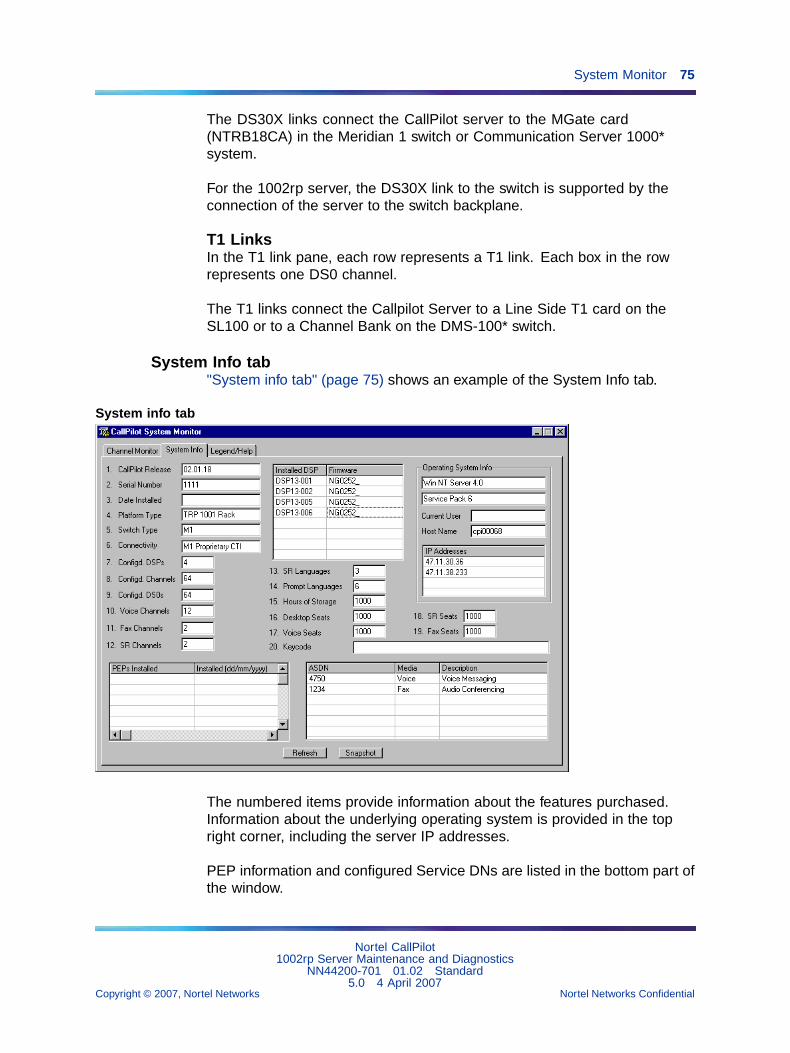
System Monitor 75
The DS30X links connect the CallPilot server to the MGate card(NTRB18CA) in the Meridian 1 switch or Communication Server 1000*system.
For the 1002rp server, the DS30X link to the switch is supported by theconnection of the server to the switch backplane.
T1 LinksIn the T1 link pane, each row represents a T1 link. Each box in the rowrepresents one DS0 channel.
The T1 links connect the Callpilot Server to a Line Side T1 card on theSL100 or to a Channel Bank on the DMS-100* switch.
System Info tab"System info tab" (page 75) shows an example of the System Info tab.
System info tab
The numbered items provide information about the features purchased.Information about the underlying operating system is provided in the topright corner, including the server IP addresses.
PEP information and configured Service DNs are listed in the bottom part ofthe window.
Nortel CallPilot1002rp Server Maintenance and Diagnostics
NN44200-701 01.02 Standard5.0 4 April 2007
Copyright © 2007, Nortel Networks Nortel Networks Confidential
.
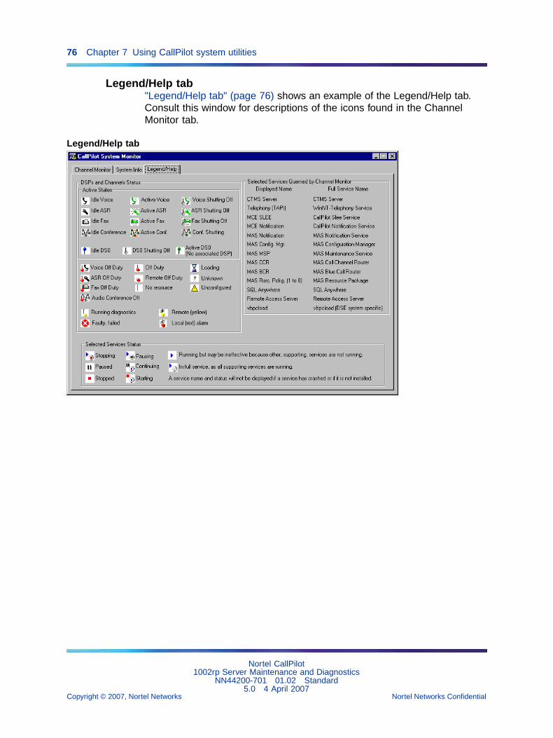
76 Chapter 7 Using CallPilot system utilities
Legend/Help tab"Legend/Help tab" (page 76) shows an example of the Legend/Help tab.Consult this window for descriptions of the icons found in the ChannelMonitor tab.
Legend/Help tab
Nortel CallPilot1002rp Server Maintenance and Diagnostics
NN44200-701 01.02 Standard5.0 4 April 2007
Copyright © 2007, Nortel Networks Nortel Networks Confidential
.

77
Chapter 8Replacing basic chassis components
In this chapter"Removing the front bezel and server cover" (page 77)
"Replacing air filters" (page 80)
"Replacing the power supply" (page 81)
"Replacing the SCA SCSI drive cage and fused power cable" (page 84)
"Replacing the cooling fan" (page 88)
"Replacing the fuse (AC system only)" (page 91)
"Replacing the alarm board" (page 93)
"Setting jumpers on the alarm board" (page 94)
"Replacing the status display panel" (page 96)
Removing the front bezel and server coverIf the maintenance task requires replacing front panel components, youmust remove the front bezel. The exception is the hard drives, which can beaccessed by simply unlocking and opening the front bezel doors.
If you require access to the server interior, remove both the front bezeland the server cover.
RequirementsBefore you remove the front bezel and server cover, gather the followingtools:
• the customer’s chassis keys for the front bezel doors
• a flat-blade screwdriver
Nortel CallPilot1002rp Server Maintenance and Diagnostics
NN44200-701 01.02 Standard5.0 4 April 2007
Copyright © 2007, Nortel Networks Nortel Networks Confidential
.

78 Chapter 8 Replacing basic chassis components
• an antistatic wrist strap
About the front bezel doorsTwo locked doors on the front of the server cover the front panel, includingthe CD-ROM drive and tape drive.
These doors are part of the front bezel. You must unlock the front paneldoors before you can remove the front bezel.
To remove the front bezel
CAUTIONRisk of equipment damageDo not attempt to move or lift the server before you have removedthe front bezel. If the front bezel is attached, the server candisengage from the front bezel and fall.
Front bezel removed
Nortel CallPilot1002rp Server Maintenance and Diagnostics
NN44200-701 01.02 Standard5.0 4 April 2007
Copyright © 2007, Nortel Networks Nortel Networks Confidential
.

Removing the front bezel and server cover 79
Step Action
1 Unlock and open the double doors of the front bezel. See A in "Frontbezel removed" (page 78).
2 Firmly grasp the front bezel by the hand-holds on either side of thechassis, and pull the front bezel from the chassis. See B in "Frontbezel removed" (page 78).
—End—
To remove the server cover
Step Action
DANGERRisk of electric shockHigh current inside the chassis can cause severe injury.
CAUTIONRisk of equipment damageTake precautions to protect internal components. Electrostaticdischarge (ESD) can damage boards and make them unusable.Wear an ESD wrist strap.
1 Remove the front bezel.
2 Power down the server and disconnect all power cords.
3 Loosen the three thumbscrews at the rear of the top cover.
4 Remove the server cover by pulling the cover toward the rear of thechassis, and then lifting it up and off.
5 Clip the lead from your ESD wrist strap to an unpainted metal sectionof the chassis.
—End—
To replace the front bezel after maintenance is completeWhen the CallPilot server maintenance is complete, replace the front bezel.
Nortel CallPilot1002rp Server Maintenance and Diagnostics
NN44200-701 01.02 Standard5.0 4 April 2007
Copyright © 2007, Nortel Networks Nortel Networks Confidential
.
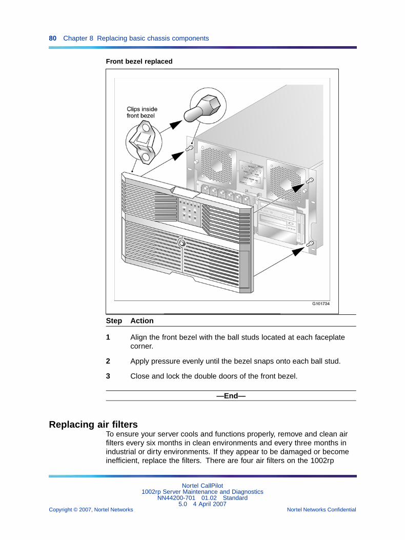
80 Chapter 8 Replacing basic chassis components
Front bezel replaced
Step Action
1 Align the front bezel with the ball studs located at each faceplatecorner.
2 Apply pressure evenly until the bezel snaps onto each ball stud.
3 Close and lock the double doors of the front bezel.
—End—
Replacing air filtersTo ensure your server cools and functions properly, remove and clean airfilters every six months in clean environments and every three months inindustrial or dirty environments. If they appear to be damaged or becomeinefficient, replace the filters. There are four air filters on the 1002rp
Nortel CallPilot1002rp Server Maintenance and Diagnostics
NN44200-701 01.02 Standard5.0 4 April 2007
Copyright © 2007, Nortel Networks Nortel Networks Confidential
.

Replacing the power supply 81
server—one inside each of the two doors of the front bezel, and two on thetop half of the front bezel. They are made of polyester foam material andare flame retardant.
RequirementsYou require the customer’s chassis keys for the front bezel.
To replace the front bezel air filter
Step Action
1 Remove the front bezel from the chassis. See "To remove the frontbezel" (page 78).
2 Pull the filters away from the Velcro strips that secure them to thebezel.
3 Replace the filter by seating the new filter pads evenly over theVelcro strips and securing them.
4 Install and lock the front bezel on the chassis.
—End—
To replace the door air filter
Step Action
1 Unlock and open the front doors.
2 The air filter is trapped between the inside of the door and the wire.The wire pivots near the key lock. Pull the wire away from the keylock to free the air filter.
3 Remove and replace the air filter.
4 Pivot the wire to trap the filter, ensuring that the ends of the wiresare pinched inside the door.
5 Close and lock the doors.
—End—
Replacing the power supplyThe power supply is hot-swappable. This means that you can replace thepower supply without powering down the server.
Nortel CallPilot1002rp Server Maintenance and Diagnostics
NN44200-701 01.02 Standard5.0 4 April 2007
Copyright © 2007, Nortel Networks Nortel Networks Confidential
.

82 Chapter 8 Replacing basic chassis components
RequirementsBefore you hot-swap a power supply, gather the following tools:
• one flat-blade screwdriver
• one Phillips screwdriver
• one antistatic wrist strap
• the replacement power supply
When to hot-swap the power supplyA green LED indicates that the power supply is working properly. If thegreen LED on the power supply module is unlit or red, the module is failingor has failed. Other indicators of failure are the alarm that sounds and thepower supply module LED on the status display that turns red.
To hot-swap a power supply
Step Action
DANGERRisk of electric shockHigh current inside the chassis can cause severe injury.
1 Loosen the thumbscrews at the top right and left of the failed powersupply module (see A in the following diagram).
If needed, use a flat-blade screwdriver. The thumbscrew must rotatefreely and not contact the chassis threads.
Nortel CallPilot1002rp Server Maintenance and Diagnostics
NN44200-701 01.02 Standard5.0 4 April 2007
Copyright © 2007, Nortel Networks Nortel Networks Confidential
.

Replacing the power supply 83
2 Grasp the molded horizontal handles on the power supply moduleand pull the power supply module free from the chassis (see B inthe preceding diagram).
3 Align the replacement module with the empty chassis bay.
4 Slide the replacement power supply module into the bay until themodule is secured by its connector. Use some force, if necessary.
5 Secure the power supply module to the chassis with twothumbscrews at the corners of the power supply faceplate.
Result: The power supply LED illuminates green.
Note: If the LED does not illuminate, remove and reinstall thepower supply with more force. If this does not work, contact yourNortel customer support representative.
—End—
Nortel CallPilot1002rp Server Maintenance and Diagnostics
NN44200-701 01.02 Standard5.0 4 April 2007
Copyright © 2007, Nortel Networks Nortel Networks Confidential
.

84 Chapter 8 Replacing basic chassis components
Replacing the SCA SCSI drive cage and fused power cableDue to the potential of an over-current condition, Nortel provides a retrofitSCSI power cable kit for the N0029330 power cable. The kit comprises animproved SCSI power cable, product label, and retrofit procedure.
The cable kit part number for all locations, except EMEA, is FR029367. AtEMEA locations, use part number N0029367.
• Only qualified field technicians who are familiar with CallPilot and RAIDshould attempt this procedure.
• A full-system backup and RAID drive consistency check must beperformed prior to replacing the SCSI power cable. These can both beperformed while the server is online.
• If at any step in the procedure, the result is not as indicated, stop andcontact your next level of support for assistance before continuing.
To replace the SCSI power cable
Step Action
1 Log into the CallPilot server.
2 Launch the MegaRAID client to check the status of the RAIDsub-system:
a. Click Start → Programs → MegaRAID Client.
b. Open the Server Selection window.
c. Select Access Mode → Full Access and click OK.
Result: The MegaRAID Power Console Plus window appears.
MegaRAID Power Console Plus
Nortel CallPilot1002rp Server Maintenance and Diagnostics
NN44200-701 01.02 Standard5.0 4 April 2007
Copyright © 2007, Nortel Networks Nortel Networks Confidential
.

Replacing the SCA SCSI drive cage and fused power cable 85
3 Open the Physical Devices window and check the drive pair settings.The table below shows the correct settings.
Drive pair settings
LEDNo
ID Channel-1 LEDNo
ID Channel-2
0 0 ONLIN A01-01 3 0 ONLIN A01-02
1 1 ONLIN A02-01 4 1 ONLIN A02-02
2 2 ONLIN A03-01 5 2 ONLIN A03-02
Note: If your settings do not match those in the table, stopand contact your next level of support for assistance beforecontinuing.
4 Check that all drives are marked in green and Online.
Note: If they are not all online, stop and contact your next levelof support for assistance before continuing.
5 Check the RAID drive consistency:
a. Select Check Consistency.
Result: The Logical Drives Configured dialog box appears.
b. Use the arrow key to highlight the first drive to be checked.
c. Press the space key to select the drive.
d. Press F10 to check consistency.
Result: The Do you wish to continue? dialog box appears.
e. Click Ok.
Result: The consistency check begins and a status dialog boxappears.
f. Repeat steps c to e for each drive until all three drives havebeen checked for consistency. This may take up to 2 hours tocomplete. If any data consistency errors are detected, they arecorrected automatically.
6 Perform a full-system backup of the CallPilot server (either to tapeor file server).
7 Review the backup logs to verify success.
8 Perform a controlled shutdown of the CallPilot software:
a. Click Ctrl+Alt+Delete and select Shutdown from the WindowsSecurity window.
Nortel CallPilot1002rp Server Maintenance and Diagnostics
NN44200-701 01.02 Standard5.0 4 April 2007
Copyright © 2007, Nortel Networks Nortel Networks Confidential
.

86 Chapter 8 Replacing basic chassis components
Result: The Shutdown Computer dialog box appears.
b. Select Shutdown.
Result: The CallPilot server turns off.
9 Remove power from the system by disconnecting the AC or DCmains.
10 Remove the bezel cover from the front of the chassis using the foursnaps located at each corner.
Bezel cover on chassis front
11 Remove the 4 Phillips-head screws from each corner of the SCSIdisk-drive cage
Chassis front with bezel removed.
12 Carefully remove the SCSI drive cage from the chassis to provideaccess to the internal cable assemblies.
Nortel CallPilot1002rp Server Maintenance and Diagnostics
NN44200-701 01.02 Standard5.0 4 April 2007
Copyright © 2007, Nortel Networks Nortel Networks Confidential
.

Replacing the SCA SCSI drive cage and fused power cable 87
SCSI drive cage attached to chassis
Note: An arrow points to the SCSI power cable in the pictureabove.
13 Unplug the original power cable from the SCA backplane and fromthe T board inside the chassis. The power cable is schematicallyshown in "SCSI power cable attached to T board" (page 87).
SCSI power cable attached to T board
Note: Leave all other cable assemblies connected. Do notdamage or disconnect other components on the SCA backplane.
Nortel CallPilot1002rp Server Maintenance and Diagnostics
NN44200-701 01.02 Standard5.0 4 April 2007
Copyright © 2007, Nortel Networks Nortel Networks Confidential
.

88 Chapter 8 Replacing basic chassis components
14 Replace the original SCSI power cable with the new cable. Securelyattach it to both the SCA backplane and the T board inside thechassis.
15 Reinstall the SCSI drive cage into the bay and screw it into place.Torque the screws at 6 to 8 inch lbs.
16 Affix a revised product label above the existing labels on the leftrear of the chassis.
Product label location on chassis
17 Replace the bezel cover on the front of the chassis.
18 Reconnect the AC or DC mains power.
19 Reboot the CallPilot server and bring it into full service.
—End—
Replacing the cooling fanThe cooling fan is hot-swappable, so you can replace the cooling fan withoutpowering down the server.
When to hot-swap the cooling fanWhen the LED associated with a cooling fan turns red, the fan requiresreplacement.
Nortel CallPilot1002rp Server Maintenance and Diagnostics
NN44200-701 01.02 Standard5.0 4 April 2007
Copyright © 2007, Nortel Networks Nortel Networks Confidential
.

Replacing the cooling fan 89
CAUTIONRisk of equipment damageUse an ESD wrist strap to protect static-sensitive components.
To hot-swap a cooling fan
Step Action
1 Remove the front bezel.
2 Use the front panel display LED to locate the defective fan.
3 Loosen the thumbscrew located on the outside of the failed coolingfan module (see A "Cooling fan thumbscrew" (page 90)).
If needed, use a flat-blade screwdriver. The thumbscrew must rotatefreely and not contact the chassis threads.
Nortel CallPilot1002rp Server Maintenance and Diagnostics
NN44200-701 01.02 Standard5.0 4 April 2007
Copyright © 2007, Nortel Networks Nortel Networks Confidential
.

90 Chapter 8 Replacing basic chassis components
Cooling fan thumbscrew
4 Unseat the cooling fan module by sliding the module horizontallyaway from the display and toward the rack rail (see B in the diagram).
Result: The module power connector unseats from the powerconnector located behind the display and LEDs.
5 Slide the failed cooling fan module out of the chassis (see C in thediagram).
6 Align the replacement cooling fan module tabs with the four supportslots on the chassis.
Ensure that the module is oriented with the thumbscrew, and insertthe tabs into the supporting slots of the chassis.
7 Slide the cooling fan module toward the front panel display and intoposition.
Result: The fan module connects with slight resistance. The fansrotate and pull air into the chassis. The cooling fan LED goes out.
Nortel CallPilot1002rp Server Maintenance and Diagnostics
NN44200-701 01.02 Standard5.0 4 April 2007
Copyright © 2007, Nortel Networks Nortel Networks Confidential
.

Replacing the fuse (AC system only) 91
8 Tighten the module thumbscrew and replace the front bezel.
—End—
Replacing the fuse (AC system only)The fuse is located below the power input socket on the rear panel. Whenthe server fuse blows, the server stops operating.
CAUTIONRisk of equipment damage and personal injuryDisconnect power from the server before replacing a fuse.
RequirementsYou require the following:
• an approved fuse for replacement
Two different types of fuses exist: one for North America, and one forinternational use. Ensure that the fuse you are replacing has beenapproved by Nortel for your region.
• a flat-blade screwdriver
To replace the fuse
Step Action
1 Power off the server.
2 Unplug the power cable from the wall outlet.
3 Unplug the power cable from the power input socket on the server.
4 Unscrew the fuse receptacle (see A in "Fuse receptacle" (page 92)).
Nortel CallPilot1002rp Server Maintenance and Diagnostics
NN44200-701 01.02 Standard5.0 4 April 2007
Copyright © 2007, Nortel Networks Nortel Networks Confidential
.

92 Chapter 8 Replacing basic chassis components
Fuse receptacle
5 Slide the fuse receptacle out of the fuse chamber.
Note: Observe how the blown fuse is positioned in thereceptacle.
6 Remove the blown fuse from the fuse receptacle.
7 Install the approved replacement fuse. Use a flat-blade screwdriverto screw in the fuse receptacle with a push and 1/4 clockwise turn.
8 Slide the fuse receptacle back into its chamber.
9 Fasten the fuse receptacle with a flat-blade screwdriver.
10 Plug the power cable back into the power input socket on the server.
11 Plug the power cable into the wall outlet.
12 Power on the server.
—End—
ATTENTIONIf the fuse blows after replacement, swap one power supply module with the other.If this does not work, call your Nortel customer support representative.
Nortel CallPilot1002rp Server Maintenance and Diagnostics
NN44200-701 01.02 Standard5.0 4 April 2007
Copyright © 2007, Nortel Networks Nortel Networks Confidential
.
Replacing the alarm board 93
Replacing the alarm boardThe 1002rp server alarm board and status panel are used to monitor andindicate the server status. The basic hardware check on page "Basichardware check" (page 17) fails if the board is defective or damaged. Whenthese units are damaged, replace them immediately.
CAUTIONRisk of equipment damageTake precautions to protect computer boards. ESD can damageboards and make them unusable. Wear an ESD wrist strap.
RequirementsBefore replacing the alarm board or panel display, gather the following tools:
• a Phillips screwdriver
• an antistatic wrist strap
• the replacement components
To replace the alarm board
Step Action
1 Power off the server.
2 Loosen the two thumbscrews securing the faceplate to the left ofthe 1002rp server power supply modules (see A in "Alarm boardcarrier" (page 94)).
If needed, use a flat-blade screwdriver. The thumbscrew must rotatefreely and not contact the chassis threads.
Nortel CallPilot1002rp Server Maintenance and Diagnostics
NN44200-701 01.02 Standard5.0 4 April 2007
Copyright © 2007, Nortel Networks Nortel Networks Confidential
.
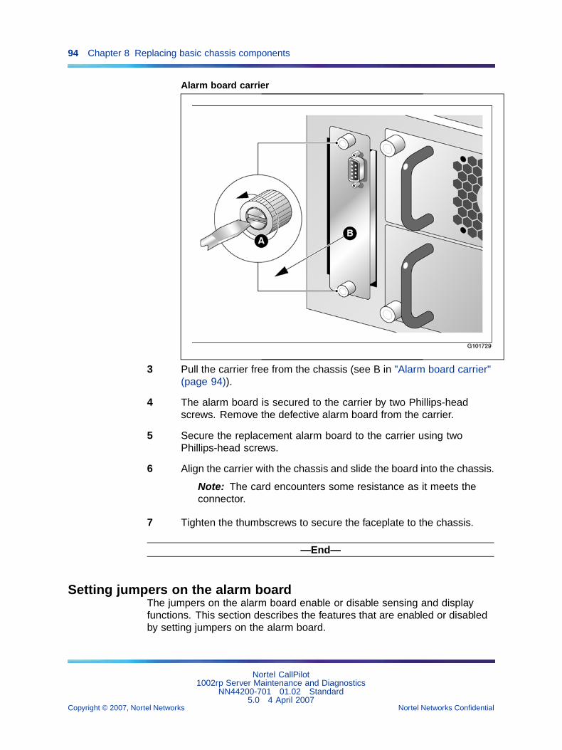
94 Chapter 8 Replacing basic chassis components
Alarm board carrier
3 Pull the carrier free from the chassis (see B in "Alarm board carrier"(page 94)).
4 The alarm board is secured to the carrier by two Phillips-headscrews. Remove the defective alarm board from the carrier.
5 Secure the replacement alarm board to the carrier using twoPhillips-head screws.
6 Align the carrier with the chassis and slide the board into the chassis.
Note: The card encounters some resistance as it meets theconnector.
7 Tighten the thumbscrews to secure the faceplate to the chassis.
—End—
Setting jumpers on the alarm boardThe jumpers on the alarm board enable or disable sensing and displayfunctions. This section describes the features that are enabled or disabledby setting jumpers on the alarm board.
Nortel CallPilot1002rp Server Maintenance and Diagnostics
NN44200-701 01.02 Standard5.0 4 April 2007
Copyright © 2007, Nortel Networks Nortel Networks Confidential
.
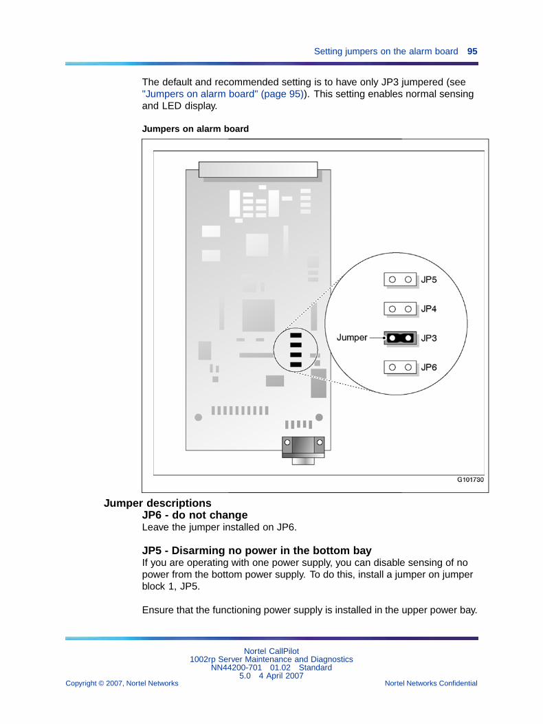
Setting jumpers on the alarm board 95
The default and recommended setting is to have only JP3 jumpered (see"Jumpers on alarm board" (page 95)). This setting enables normal sensingand LED display.
Jumpers on alarm board
Jumper descriptionsJP6 - do not changeLeave the jumper installed on JP6.
JP5 - Disarming no power in the bottom bayIf you are operating with one power supply, you can disable sensing of nopower from the bottom power supply. To do this, install a jumper on jumperblock 1, JP5.
Ensure that the functioning power supply is installed in the upper power bay.
Nortel CallPilot1002rp Server Maintenance and Diagnostics
NN44200-701 01.02 Standard5.0 4 April 2007
Copyright © 2007, Nortel Networks Nortel Networks Confidential
.

96 Chapter 8 Replacing basic chassis components
JP4Not used.
JP3 - LED displayInstall a jumper on jumper block 1, JP3, to configure the alarm board tosend alarm signals to the full array of LEDs. This is the default setting andthe required setting for normal server operation.
If this jumper is not installed over both pins, the alarm board does not sendthe correct format of signals to the front panel display.
Replacing the status display panelThe display is located at the front of the chassis and is cabled to the rearof the chassis and the alarm board.
To replace the status display panel
Step Action
CAUTIONRisk of equipment damageUse an ESD wrist strap to protect static-sensitive components.
1 Power off the server.
2 Remove the top cover and the front bezel from the chassis.
3 Remove the cooling fans (see "Replacing the cooling fan" (page 88)).
The cooling fans block the access to the status panel.
4 Loosen the four Phillips-head screws that secure the status displaypanel to the front of the chassis (see A in "Status display panel."(page 97))
Nortel CallPilot1002rp Server Maintenance and Diagnostics
NN44200-701 01.02 Standard5.0 4 April 2007
Copyright © 2007, Nortel Networks Nortel Networks Confidential
.

Replacing the status display panel 97
Status display panel.
5 Label and remove the 40-pin flat cable from the back of the statusdisplay panel.
6 Move the defective status display panel towards the back of thechassis, and then lift it out of the chassis (see B and C in thediagram).
7 Set the replacement status display panel into position, and secure itto the chassis by replacing the Phillips-head screws.
8 Reconnect the cable.
9 Replace the top cover and front bezel.
—End—
Nortel CallPilot1002rp Server Maintenance and Diagnostics
NN44200-701 01.02 Standard5.0 4 April 2007
Copyright © 2007, Nortel Networks Nortel Networks Confidential
.

98 Chapter 8 Replacing basic chassis components
Nortel CallPilot1002rp Server Maintenance and Diagnostics
NN44200-701 01.02 Standard5.0 4 April 2007
Copyright © 2007, Nortel Networks Nortel Networks Confidential
.

99
Chapter 9Replacing media drives
In this chapter"Replacing a faulty hard drive" (page 99)
"About the media drive bay" (page 103)
"Removing the media drive carrier from the chassis" (page 103)
"Replacing a tape, CD-ROM or floppy drive" (page 106)
"Installing a tape drive" (page 108)
Replacing a faulty hard driveThe hard drives are hot-swappable. This means that you can replace afaulty hard drive without powering down the server.
ATTENTIONReplacement hard drives must be the same size or larger than the hard drivesbeing replaced
When to hot-swap hard drivesWith a RAID controller, hot-swap device drivers, and operating systemsupport, faulty SCA SCSI hard drives can be hot-swapped on the 1002rpserver.
Note: Identify which hard drive to remove using the Windows EventViewer (see "Viewing event logs" (page 23)). The appearance of eventcodes such as 40211(disk access error) or 40218 (error reading orwriting multimedia volume) may be an indication of a failing disk drive.
Use the RAID management software to check if any drives are in a failedstate.
Nortel CallPilot1002rp Server Maintenance and Diagnostics
NN44200-701 01.02 Standard5.0 4 April 2007
Copyright © 2007, Nortel Networks Nortel Networks Confidential
.

100 Chapter 9 Replacing media drives
The following image shows a failed drive highlighted in red with thecorresponding logical drive highlighted in yellow (degraded mode)
Failed hard drive displayed in red
RAID SCSI hard drive configuration"RAID SCSI hard drive configurations" (page 100) shows proper SCSI drivebay, channel, and ID configurations in the hot-swappable drive bay. TheSCSI backplane assigns the SCSI IDs as shown.
RAID SCSI hard drive configurations
Hard drive baySCSIchannel SCSI ID Logical drive labela
1 (far left) 0 0 A01-01 (primary hard drive)
2 0 1 A02-01 (primary hard drive)
3 0 2 A03-01 (primary hard drive)
4 1 0 A01-02 (secondary hard drive)
a. RAID pairs (logical drives) consist of the following pairs: hard drives 1 and4,2 and 5, and 3 and 6. these pairs are represented in the software with thelables A01-01 and A01-02, A02-01 and A02-02, and A03-02, A03-02 where thefirst number is the logical drive number (for example, A03) and the secondnumber indicates if it is the primary or secondary hard drive (01 for primaryand 02 for secondary)
Nortel CallPilot1002rp Server Maintenance and Diagnostics
NN44200-701 01.02 Standard5.0 4 April 2007
Copyright © 2007, Nortel Networks Nortel Networks Confidential
.

Replacing a faulty hard drive 101
Hard drive baySCSIchannel SCSI ID Logical drive labela
5 1 1 A02-02 (secondary hard drive)
6 (far right) 1 2 A03-02 (secondary hard drive)
a. RAID pairs (logical drives) consist of the following pairs: hard drives 1 and4,2 and 5, and 3 and 6. these pairs are represented in the software with thelables A01-01 and A01-02, A02-01 and A02-02, and A03-02, A03-02 where thefirst number is the logical drive number (for example, A03) and the secondnumber indicates if it is the primary or secondary hard drive (01 for primaryand 02 for secondary)
To replace hot-pluggable SCA SCSI hard drives
Step Action
CAUTIONRisk of equipment damageUse an ESD wrist strap to protect static-sensitive components.
1 Ensure the new hard drive has the SCSI ID set to 0, terminationdisabled, and parity checking enabled.
2 Open the front bezel doors.
3 Locate the SCA SCSI drive frame below a cooling fan and besidethe media drive.
4 Loosen the two thumbscrews on the carrier of the faulty hard drive,and remove the carrier from the chassis.
Nortel CallPilot1002rp Server Maintenance and Diagnostics
NN44200-701 01.02 Standard5.0 4 April 2007
Copyright © 2007, Nortel Networks Nortel Networks Confidential
.

102 Chapter 9 Replacing media drives
Remove SCSI carrier from chassis
5 Remove the faulty drive by loosening the four Phillips-head screwsthat secure it to the carrier.
6 Attach the new drive to the carrier by four Phillips-head screws.
7 Align the carrier with the drive frame and slide it into the chassis.
Note: Expect resistance as the carrier and backplaneconnectors meet.
8 Fasten the two thumbscrews.
9 Close the front bezel and lock it.
—End—
Nortel CallPilot1002rp Server Maintenance and Diagnostics
NN44200-701 01.02 Standard5.0 4 April 2007
Copyright © 2007, Nortel Networks Nortel Networks Confidential
.

Removing the media drive carrier from the chassis 103
About the media drive bayMedia drive bays contain media devices, including CD-ROM, tape, andfloppy drives. If your media drives become damaged or you want toupgrade, you can replace these drives. This section provides procedures forreplacing or upgrading any device in the media drive bay.
To replace media drives
Step Action
Perform the procedures in the following order to replace media drives:
1 "Removing the media drive carrier from the chassis" (page 103)
2 "Replacing a tape, CD-ROM or floppy drive" (page 106)
—End—
Removing the media drive carrier from the chassisWhen replacing the media hard drives, the first step is to remove the mediadrive carrier from the media drive bay.
RequirementsTo remove the media drive carrier from the media drive bay, you requirethe following:
• keys for the front bezel doors
• a Phillips screwdriver
• cable identification labels
• a pen or pencil
Locate the media drivesThe media drives (CD-ROM drive, tape drive, and floppy drive) are shown inthe bottom right corner shown in "Media drives" (page 104).
Nortel CallPilot1002rp Server Maintenance and Diagnostics
NN44200-701 01.02 Standard5.0 4 April 2007
Copyright © 2007, Nortel Networks Nortel Networks Confidential
.

104 Chapter 9 Replacing media drives
Media drives
Media drive carrierThe media drives are housed in a media drive carrier that can be removedfrom the server, as described later in this section. Where no media device isinstalled, a blank panel is secured to the media drive carrier for protection.
Media drive carrier slot assignmentThe carrier is designed to stack three devices horizontally, and to house thefloppy drive vertically to the right side of the carrier frame.
Nortel CallPilot1002rp Server Maintenance and Diagnostics
NN44200-701 01.02 Standard5.0 4 April 2007
Copyright © 2007, Nortel Networks Nortel Networks Confidential
.

Removing the media drive carrier from the chassis 105
To remove the media drive carrier from the chassis
Step Action
DANGERRisk of electrocutionHigh current inside the chassis can cause severe injury.
CAUTIONRisk of equipment damageElectrostatic discharge due to improper handling can causecomponents to be damaged or rendered unusable.
1 Remove the front bezel from the chassis. See "Removing the frontbezel and server cover" (page 77).
2 Locate the media drive carrier, and loosen the four Phillips-headscrews and washers securing the carrier to the drive bay, as shownin "Remove media drive from chassis" (page 105).
Remove media drive from chassis
Nortel CallPilot1002rp Server Maintenance and Diagnostics
NN44200-701 01.02 Standard5.0 4 April 2007
Copyright © 2007, Nortel Networks Nortel Networks Confidential
.

106 Chapter 9 Replacing media drives
3 Hold cables away from the drive bay as you pull the media drivecarrier away from the chassis until the connectors attached behindthe components can be reached.
CAUTIONRisk of equipment damageTo avoid damaging cables during this procedure, ensurethat no cables are crossed when moving the media drivecarrier in and out of the drive bay.
4 Label and disconnect cables from installed media drives, and thenfree the carrier from the chassis.
—End—
Replacing a tape, CD-ROM or floppy driveThis section describes how to replace a media drive (tape, CD-ROM, orfloppy drive) in the media drive carrier.
To replace a media drive
Step Action
CAUTIONRisk of equipment damageUse an ESD wrist strap to protect static-sensitive components.
1 Remove the media drive carrier from the chassis (see "Removingthe media drive carrier from the chassis" (page 103)).
2 Remove the faulty drive from the media drive carrier and save thescrews (see the diagrams that follow).
Note: To remove the tape drive or CD-ROM drive, you mustfirst remove the floppy drive.
Nortel CallPilot1002rp Server Maintenance and Diagnostics
NN44200-701 01.02 Standard5.0 4 April 2007
Copyright © 2007, Nortel Networks Nortel Networks Confidential
.

Replacing a tape, CD-ROM or floppy drive 107
Replace media drive - step 1
Replace media drive - step 2
Nortel CallPilot1002rp Server Maintenance and Diagnostics
NN44200-701 01.02 Standard5.0 4 April 2007
Copyright © 2007, Nortel Networks Nortel Networks Confidential
.
108 Chapter 9 Replacing media drives
3 If you are installing a tape drive, configure it as described in "Toconfigure the tape drive" (page 109).
4 Slide the new drive into the media drive carrier, and secure it withthe screws that were previously removed.
5 Reattach any media drives that you removed to access a specificmedia drive slot.
6 Position the media drive carrier in the media drive bay, leavingenough room to reach behind the carrier, and attach the connectors.
7 Carefully connect the existing signal and power cables as shown in"Cabling example" (page 109).
Note: If your tape drive is a narrow device, you require awide-to-narrow adapter to connect to the wide SCSI cable.
8 Slide the carrier into the media drive bay.
Note: Ensure that the cables are free and undamaged.
9 Secure the media drive carrier to the chassis with four Phillips-headscrews.
10 Replace and lock the front bezel.
—End—
Installing a tape driveThis procedure provides instructions for installing a tape drive on a serverthat currently does not have a tape drive.
Nortel CallPilot1002rp Server Maintenance and Diagnostics
NN44200-701 01.02 Standard5.0 4 April 2007
Copyright © 2007, Nortel Networks Nortel Networks Confidential
.

Installing a tape drive 109
Cabling example
To configure the tape drive
Note: Some settings may already be properly configured. If it is notclear from the drive manufacturer’s documentation how to set jumpers,contact your Nortel technical support representative.
Step Action
1 Set the SCSI ID to 6.
2 Disable the Active Terminators (Term Enable).
Note: Termination is provided by an active SCSI terminatorthat you connect to the end of the SCSI cable (see "Cablingexample" (page 109)).
3 Enable Parity Checking.
4 Enable Termination power (TPWR).
Nortel CallPilot1002rp Server Maintenance and Diagnostics
NN44200-701 01.02 Standard5.0 4 April 2007
Copyright © 2007, Nortel Networks Nortel Networks Confidential
.

110 Chapter 9 Replacing media drives
5 Leave the remaining settings at the default values.
—End—
To install a new tape drive (no tape drive previously installed)
Step Action
CAUTIONRisk of equipment damageUse an ESD wrist strap to protect static-sensitive components.
1 Courtesy down CallPilot, and then power down the server.
2 Ensure that the tape drive settings are as described in ""To configurethe tape drive" (page 109)".
3 Remove the chassis cover.
4 Remove the media drive carrier (see "Removing the media drivecarrier from the chassis" (page 103)).
5 Slide the new tape drive into the media drive carrier, and secure itwith four undercut Phillips-head screws.
Note: You may need to first remove other media drives from thecarrier to access the tape drive slot.
6 Reattach any media drives that you removed to access the tapedrive slot.
7 Position the media drive carrier in the media drive bay, leavingenough room to reach behind the carrier, and attach the connectors.
8 Carefully connect the existing signal and power cables as shown in"Cabling example" (page 109).
9 Slide the carrier into the media drive bay.
Note: Ensure that the cables are free and undamaged.
10 Secure the media drive carrier to the chassis with four Phillips-headscrews.
Result:The tape drive is installed.
Nortel CallPilot1002rp Server Maintenance and Diagnostics
NN44200-701 01.02 Standard5.0 4 April 2007
Copyright © 2007, Nortel Networks Nortel Networks Confidential
.

Installing a tape drive 111
11 Replace the chassis cover and front bezel.
12 Power on the server.
Result: The tape drive is detected by Windows, and the tape driveis ready for use.
—End—
Nortel CallPilot1002rp Server Maintenance and Diagnostics
NN44200-701 01.02 Standard5.0 4 April 2007
Copyright © 2007, Nortel Networks Nortel Networks Confidential
.

112 Chapter 9 Replacing media drives
Nortel CallPilot1002rp Server Maintenance and Diagnostics
NN44200-701 01.02 Standard5.0 4 April 2007
Copyright © 2007, Nortel Networks Nortel Networks Confidential
.
113
Chapter 10RAID operations
In this chapter"Outlining RAID functions" (page 113)
"Configuring RAID firmware, driver, and power console" (page 113)
"Replacing the LSI1600 card with LSI320-2" (page 114)
"Configuring the RAID controller after a hardware change" (page 116)
"Splitting the RAID drives" (page 119)
"Synchronizing RAID drives" (page 121)
Outlining RAID functionsRedundant Array of Independent Disks (RAID) is a technology that cancombine two or more drives for fault tolerance and continued systemperformance. The CallPilot RAID controller is a PCI RAID SCSI card thatprovides high-performance disk mirroring. CallPilot uses RAID Level 1.
With Level 1 mirroring, two equal-capacity disk drives mirror one another.One disk drive serves as the backup copy of the other disk drive. If one diskdrive fails, the other continues to run.
Configuring RAID firmware, driver, and power consoleVerifying the RAID configuration
There is a direct relationship between the driver, firmware and PowerConsole utility versions used with a RAID card. While mixing driver versionswith firmware is not critical, mixing Power Console Utility with the wrong
Nortel CallPilot1002rp Server Maintenance and Diagnostics
NN44200-701 01.02 Standard5.0 4 April 2007
Copyright © 2007, Nortel Networks Nortel Networks Confidential
.

114 Chapter 10 RAID operations
driver or firmware can lead to system instability and data corruption. "RAIDdriver, firmware, and Power console configuration." (page 114) shows theaccepted and tested combinations for Windows 2003
RAID driver, firmware, and Power console configuration.
RAID card Driver FirmwareMegaRAIDPower Console
LSI1600 6.45 (6.36 workstemporarily but mustbe upgraded)
111U 5.00i
LSI320-2 6.45 (6.36 workstemporarily but mustbe upgraded)
1L37 5.00i
To determine the current RAID firmware version:
Step Action
1 Select Objects Menu → Adapter → Adapter Information.
2 Launch the MegaRAID client using: Start → Programs → PowerConsole Plus → Launch Client.
3 From the MegaRAID Power Console Plus, Server Selection window,select Access Mode → Full Access to view or change configurationinformation and click OK.
4 Select Adapter → Properties.
5 If the configuration is not one of the valid configuration in "RAIDdriver, firmware, and Power console configuration." (page 114),perform a firmware update. For instructions, see "Replacing theLSI1600 card with LSI320-2" (page 114).
—End—
Replacing the LSI1600 card with LSI320-2Use this procedure to replace a failed LSI1600 RAID card.
Nortel CallPilot1002rp Server Maintenance and Diagnostics
NN44200-701 01.02 Standard5.0 4 April 2007
Copyright © 2007, Nortel Networks Nortel Networks Confidential
.

Replacing the LSI1600 card with LSI320-2 115
To replace the LSI1600 card with the LSI320-2 card.
Step Action
WARNINGNortel strongly recommends that you not perform low levelformatting. Performing low level formatting results in the drivesbecoming unusable.
ATTENTIONIf your replacement RAID card has been previously used and holds an existingconfiguration, the system will report a mismatch between the controller NVRAMand Drive MetaData. The steps below will correct the mismatch.
1 Power up the server and click Ctrl+M to enter the utility.
2 Select Objects → Adapter → Other Adapter to set the following:
a. Set Force Boot to On.
b. Set Auto-Rebuild to Disabled.
c. Select Objects → Channel and ensure channel speed is 160M.((Default for LSI320 is 320M).
d. Repeat for all channels.
3 Exit the utility and reboot the server.
4 Set the server to boot from CD.
5 Insert the RAID Update Utility CD and reboot the server.
Result: The DOS boot menu appears.
6 Select Update LSI320-2 Firmware.
Result: The system will prompt twice to confirm you are upgradingthe firmware.
7 Answer Y to both questions.
Result:The system upgrades the firmware and asks you to reboot.
8 Allow the system to reboot to Windows 2003.
9 Insert the RAID Update Utility CD and unzip the RAIDUP.EXE file.
Result: A directory called RAIDUP is created on C:\ drive
Nortel CallPilot1002rp Server Maintenance and Diagnostics
NN44200-701 01.02 Standard5.0 4 April 2007
Copyright © 2007, Nortel Networks Nortel Networks Confidential
.
116 Chapter 10 RAID operations
10 Locate SCSI controllers → LSI Adapter in the RAIDUP directory.Double click on it, then select Driver.
Result: You are asked to choose the Upgrade Driver.
11 Point to the c:\raidup\Win2k3 folder.
12 The system asks you to reboot.
Result: The system reboots to Windows 2003.
13 Check the driver, firmware and Power Console configuration.
a. Open the MegaRAID Power Console from the Start → Programsmenu.
b. Select Help About from the menu and verify the MegaRAIDPower Console version is 5.00i.
c. Select Adapter → Properties and verify the firmware version is1L37 and the board type is LSI320-2.
d. Exit the Power Console.
14 Right click on C:\WINNT\SYSTEM32\DRIVERS\mraid3xx.sys andselect Properties → Version. Verify the Driver version is 6.45.
—End—
Configuring the RAID controller after a hardware changeThe RAID card’s configuration is stored on both the card and on the harddrive, so typically you are not required to reconfigure RAID unless you aremaking a change to the RAID system (for example, if you replace the harddrives with higher-capacity hard drives).
CAUTIONRisk of data lossThis procedure requires that the logical drive be initialized. Whenyou initialize the logical drive, all data on the hard drives is erased.
Do not perform this procedure unless you are replacing thehard drives, or you are rebuilding the CallPilot system (that is,reinstalling the Windows operating system and CallPilot software).
WARNINGNortel strongly recommends that you not perform low levelformatting. Performing low level formatting results in the drivesbecoming unusable.
Nortel CallPilot1002rp Server Maintenance and Diagnostics
NN44200-701 01.02 Standard5.0 4 April 2007
Copyright © 2007, Nortel Networks Nortel Networks Confidential
.

Configuring the RAID controller after a hardware change 117
To configure an LSI Elite 1600 or LSI320-2 RAID system
Step Action
1 Turn on the server and press Ctrl+M when prompted during systembootup.
Note: The Ctrl+M utility can take up to 1 minute to launch. Thesystem may appear frozen. Do not reset.
2 From the Management menu, select Objects and press Enter.
3 From the Objects menu select Adapter and press Enter.
4 From the Adapter menu select Factory Default.
5 Select Yes to confirm the selection and press Enter.
6 Press Ctrl+Alt+Delete when prompted to restart system.
7 During bootup, press Ctrl+M to re-enter the RAID setup utility.
8 From the Management menu select Objects → Adapter, then ensurethe values are set as follows:
Flex RAID Power Fail: EnabledFast Initialization: OnDisk Spin up Timing: 1 Disk every 6 secsCache Flush Timings: Every 4 secondsRebuild Rate: 30%Alarm Control: EnabledOther Adapter Settings:— Emulation: Mass Storage— Auto Rebuild: Disabled— Initiator ID: 7— Cluster Mode: Disabled— Multiple PCI Delayed Transactions: Disabled— Force Boot: On— Coercion Algorithm: GigaByte Way— Cc Restoration: Enabled
Note: The Coercion Algorithm must be set properly. Oncechanged, it cannot be changed again. The only way to resetit is to reconfigure RAID from scratch and load the defaultconfiguration, then reboot.
9 Select Objects → Channel and press Enter. Ensure that the valuesare set as follows:
Termination State: Enabled
Nortel CallPilot1002rp Server Maintenance and Diagnostics
NN44200-701 01.02 Standard5.0 4 April 2007
Copyright © 2007, Nortel Networks Nortel Networks Confidential
.

118 Chapter 10 RAID operations
SCSI Transfer Rate: 160M
10 In the Configure menu, select New Configuration. Press Yes toproceed.
Result: The system should display both SCSI channels, eachhaving three drives. SCSI ID’s should be listed in order from 0 to 2for each channel, starting from the top. All disk drives should be inREADY state.
Note: Do not use the Load command on the Configure menu.This command is not for RAID operations.
11 Create the first logical drive by selecting A01-01 (first drive fromchannel 0), to A01-02 (first drive from channel 1) and pressing thespace bar.
Result: After selection, the drives will blink.
12 Press Enter to create the first logical drive.
13 Repeat the process for the second and third logical drives to createpacks as follows:
A02-01 and A02-02 as second pack
A03-01 and A03-02 as third pack
14 Press Enter or F10 to configure the logical drives.
15 Press the space bar to Select Configuration Array. Span-1 appearsin the box opened for A01 logical drive. DO NOT select and pressthe space bar for the other logical drives at this point.
16 Configure logical drive A01, by pressing F10.
RAID 1:Size: accept the size displayAcceptSPAN = NO
17 Highlight Accept and press Enter to accept these new values.Repeat for the two remaining logical drives.
Result: After the last logical drive, the system will prompt you tosave the configuration.
18 Highlight YES and press Enter.
19 Press ESC twice to exit the submenus.
20 In the Management menu choose the Initialize submenu.
21 Press F2 to select all three logical drives.
Nortel CallPilot1002rp Server Maintenance and Diagnostics
NN44200-701 01.02 Standard5.0 4 April 2007
Copyright © 2007, Nortel Networks Nortel Networks Confidential
.

Splitting the RAID drives 119
22 Press F10 and consecutively select YES to initialize the drive packs.
23 When the initialization is complete, press any key to return to theManagement menu.
24 Press ESC to exit the utility. Save the configuration when prompted.
25 Press Ctrl+Alt+Delete as indicated by the menu to reboot.
—End—
Splitting the RAID drivesEnsure that your system is in full working order and the RAID hardwareconfiguration is set up properly as described on "Configuring the RAIDcontroller after a hardware change" (page 116).
ATTENTIONYou must verify that the RAID channel 1 is connected to the first three hard driveson the left as facing the machine, and channel 2 is connected to the last three tothe right. Either open the lid and follow the cables or take one hard drive offlineand observe which drive is marked FAIL by the system. If the drive matches thegraphic location on the Windows MegaRAID console, proceed with the next step.
ATTENTIONThe drives must not be un-seated, re-seated or disconnected during the RAIDsplitting process unless you are planning to replace the drives.
Full data backup
ATTENTIONAs an extra precaution, it is recommended that a full system backup be performedPRIOR to performing a RAID-split. For more information on system backups referto the CallPilot Manager online help.
Verifying consistency on the drivesThis optional consistency check on the RAID system’s logical drive ensuresthat the data on the drives is identical. If any errors are found, they arecorrected automatically. Perform a consistency check before you split theRAID system pack. A good data backup on an offline drive will be importantif you need to revert to the CallPilot system from an unsuccessful upgradeor update. The consistency check can take up to 2 hours to complete.
Nortel CallPilot1002rp Server Maintenance and Diagnostics
NN44200-701 01.02 Standard5.0 4 April 2007
Copyright © 2007, Nortel Networks Nortel Networks Confidential
.
120 Chapter 10 RAID operations
To perform a consistency check
Step Action
1 Restart the CallPilot system and press Ctrl+M when prompted, toenter the RAID setup utility during bootup.
2 From the Management Console, select Check Consistency.
Result: The Logical Drives Configured dialog box displays.
3 Use the arrow key to highlight the first drive to be checked.
4 Press the space key to select the drive.
5 Press F10 to check consistency.
Result: The "Do you wish to continue?" dialog box appears.
6 Click Ok.
Result: The consistency check begins and a status dialog boxappears.
7 Repeat steps 3 to 6 for each drive until all three drives have beenchecked for consistency.
—End—
To split the RAID
Step Action
ATTENTIONTo split the RAIDBecause the 1002rp has three physical drives, the RAID splittingmust be done at the Ctrl+M utility level. Do not perform this procedure using theWindows MegaRAID console. There is a risk of database corruption.
1 Restart the CallPilot system and press Ctrl+M when prompted, toenter the RAID setup utility during bootup.
2 From the Management menu select Objects > Physical Drive.
Result: A list of all drives organized per channel appears.
3 Select the A01- 2 drive using the cursor and press Enter.
4 Select Fail Drive.
Result: A warning message box appears. Ignore it and select Yes.The drive status changes to FAILED. The alarm should start beeping.
Nortel CallPilot1002rp Server Maintenance and Diagnostics
NN44200-701 01.02 Standard5.0 4 April 2007
Copyright © 2007, Nortel Networks Nortel Networks Confidential
.

Synchronizing RAID drives 121
5 Repeat this process for the remaining two drives present on Channel2.
6 Press Esc three times to exit the Ctrl+M utility.
7 Reboot.
Result: The system reports that three drives are in critical mode andstarts beeping. This is OK; the system will still reboot.
ATTENTIONThe alarm can be silenced, but under no circumstances should it bedisabled. On the toolbar, select Objects → Adapter → Alarm Console→ Silence Alarm from the toolbar.
At this point, the RAID is split, and the drives marked FAILEDbecome the backup drives and are no longer written to. A PEPinstallation can now be done without impact to the ’backup’ drives.
—End—
Synchronizing RAID drives
To synchronize the RAID after a successful operation
Step Action
1 Without shutting down the server, right-click the first drive onChannel 2.
Example: (0) A1-2-Failed.
2 From the pop-up menu select Rebuild. When the Rebuild iscomplete, repeat the process for the remaining two drives onChannel 2.
Result: When all three drives are rebuilt,
a. All three drive status’ changes to ONLINE.
b. The color of the icons changes to green.
c. The alarm should stop beeping unless it was temporarilysilenced.
Note: The process can take up to 1 hour. DO NOT shut downthe machine before the rebuild is complete.
3 Monitor the rebuild by opening the Windows MegaRAID console.
Nortel CallPilot1002rp Server Maintenance and Diagnostics
NN44200-701 01.02 Standard5.0 4 April 2007
Copyright © 2007, Nortel Networks Nortel Networks Confidential
.

122 Chapter 10 RAID operations
—End—
To synchronize the RAID after an unsuccessful operation
Step Action
If the operation has failed, the system needs to be returned to the originalconfiguration.
1 Reboot the CallPilot server.
2 Press Ctrl+M while the server is booting.
Result: The RAID configuration utility opens.
3 Break the mirroring of the logical drives.
a. Select Objects → Physical Drive.
Note: All server drives on channel 1 must be online.
b. Select CH1 ID0 (A01-01) and press Enter.
c. Select Fail Drive and press Enter.
d. Select Yes to confirm the fail action and press Enter.
e. Repeat these steps for each remaining drive on channel 2: CH1ID1 (A02-01) and CH1 ID2 (A03-01).
4 Bring the drives on channel 2 online (the drives on which theprevious CallPilot release is installed).
a. Select Objects → Physical Drive.
b. Select CH2 ID0 (A01-02) and press Enter.
c. Select Make Online and press Enter.
d. Select Yes to confirm that the driver must be brought onlineand press Enter.
e. Repeat these steps for each remaining drive on channel 2: CH2ID1 (A02-02) and CH2 ID2 (A03-02).
5 Press Esc to return to the Objects menu.
6 Press Esc to return to the Management menu.
7 Press Esc to exit the RAID configuration utility.
Result: A confirmation box appears.
Nortel CallPilot1002rp Server Maintenance and Diagnostics
NN44200-701 01.02 Standard5.0 4 April 2007
Copyright © 2007, Nortel Networks Nortel Networks Confidential
.

Synchronizing RAID drives 123
8 Click Yes to confirm that you want to exit the RAID configurationutility and press Enter.
9 Press Ctrl+Alt+Delete to reboot the server.
—End—
Nortel CallPilot1002rp Server Maintenance and Diagnostics
NN44200-701 01.02 Standard5.0 4 April 2007
Copyright © 2007, Nortel Networks Nortel Networks Confidential
.

124 Chapter 10 RAID operations
Nortel CallPilot1002rp Server Maintenance and Diagnostics
NN44200-701 01.02 Standard5.0 4 April 2007
Copyright © 2007, Nortel Networks Nortel Networks Confidential
.

125
Chapter 11Configuring MPB96 boards
In this section"Determining board and card configuration" (page 125)
"Identifying hardware components" (page 126)
"Installing valid configurations" (page 128)
Determining board and card configuration
T1 switch connectivityThere are two valid configurations for PCI T1 cards and MPB 96 boardswith T1 switch connectivity. "MPB 96 with T1 switch" (page 125) showsvalid configurations.
MPB 96 with T1 switch
MPB96 boards PCI T1 cards Max. Channels MPU
1 2 96 96
3 4 192 288
Nortel CallPilot1002rp Server Maintenance and Diagnostics
NN44200-701 01.02 Standard5.0 4 April 2007
Copyright © 2007, Nortel Networks Nortel Networks Confidential
.

126 Chapter 11 Configuring MPB96 boards
Meridian 1 (M1)/Communication Server 1000 (CS 1000) switchconnectivityThere are two valid configurations for MPB 96 boards with M1/CS 1000switch connectivity. "MPB 96 with M1/CS1000 switch" (page 126) showsvalid configurations.
MPB 96 with M1/CS 1000 switch
MPB96 boards Max. Channels MPU
1 96 96
3 192 288
Determine which configuration applies to your system.
Taking safety precautionsBefore you make any changes to the server hardware, follow these safetyprecautions:
• Respect appropriate ESD rules.
• Power the system OFF.
• Do not drop and leave screws inside the server.
• Do not drop hard objects (such as screwdrivers) inside the server asthis can damage the server.
Identifying hardware components"1002rp server chassis" (page 127) shows the arrangement of slots in a1002rp server chassis.
Nortel CallPilot1002rp Server Maintenance and Diagnostics
NN44200-701 01.02 Standard5.0 4 April 2007
Copyright © 2007, Nortel Networks Nortel Networks Confidential
.

Identifying hardware components 127
1002rp server chassis
"D480JCT1 PCI T1 board" (page 127) shows the layout of jumpers andswitches on the D/480JCT-2T1 PCI T1 board.
D/480JCT-2T1 PCI T1 board
Nortel CallPilot1002rp Server Maintenance and Diagnostics
NN44200-701 01.02 Standard5.0 4 April 2007
Copyright © 2007, Nortel Networks Nortel Networks Confidential
.

128 Chapter 11 Configuring MPB96 boards
Installing valid configurations
ATTENTIONYou must use one of the valid configurations and respect the slot map or thesystem behavior will be erratic.
T1 switch connectivity
To configure one MPB96 and two T1 PCI cards
Step Action
1 Plug the MPB96 card in PCI slot 3.
2 On the first Intel D/480JCT-2T1 PCI card:
a. Set the card SW100 ID rotary dial switch to 0.
b. Ensure that there are no termination jumpers installed on P700.
3 Plug the first Intel D/480JCT-2T1 PCI card 1 in PCI slot 4.
4 On the second Intel D/480JCT-2T1 PCI card:
a. Set the card SW100 ID rotary dial switch to 1.
b. Install a termination jumper on P700 3&4 termination jumpersON (to enable CT Bus termination).
Note: Only one Intel D/480JCT-2T1 PCI card in the system (thelast on the CT Bus cable) should have the termination jumperset to ON.
5 Plug the Intel D/480JCT-2T1 PCI card 1 in PCI slot 5.
6 Connect the 3 drop CT-Bus cable so all three connectors aresecurely connected to all cards.
Note: If a 7 drop cable is used in this configuration, ensurethat the end connectors are connected to the end cards and noconnector is left dangling at any end of the cable.
—End—
To configure three MPB96 and four T1 PCI cards
Step Action
1 Plug the MPB96 card in PCI slot 3.
2 On the first Intel D/480JCT-2T1 PCI card:
Nortel CallPilot1002rp Server Maintenance and Diagnostics
NN44200-701 01.02 Standard5.0 4 April 2007
Copyright © 2007, Nortel Networks Nortel Networks Confidential
.

Installing valid configurations 129
a. Set the card SW100 ID rotary dial switch to 0.
b. Ensure that there are no termination jumpers installed on P700.
3 Plug the Intel D/480JCT-2T1 PCI card 1 in PCI slot 4.
4 On the second Intel D/480JCT-2T1 PCI card:
a. Set the card SW100 ID rotary dial switch to 1.
b. Ensure that there are no termination jumpers installed on P700.
5 Plug the Intel D/480JCT-2T1 PCI card 2 in PCI slot 5.
6 Plug the MPB96 card in PCI slot 6.
7 On the third Intel D/480JCT-2T1 PCI card:
a. Set the card SW100 ID rotary dial switch to 2.
b. Ensure that there are no termination jumpers installed on P700.
8 Plug the Intel D/480JCT-2T1 PCI card 3 in PCI slot 7.
9 On the fourth Intel D/480JCT-2T1 PCI card:
a. Set the card SW100 ID rotary dial switch to 3.
b. Ensure that there are no termination jumpers on P700 pins 3and 4.
10 Plug the Intel D/480JCT-2T1 PCI card 4 in PCI slot 8.
11 Plug the MPB96 card in PCI slot 9.
12 Connect the 7 drop CT Bus cable to all MPB96 and T1 cards.Ensure that the end connectors are connected to the end cards andno connector is left dangling at any end of the cable.
—End—
M1/CS 1000 switch connectivityTo configure one MPB96 boardPlug the MPB96 card in PCI slot 3.
To configure three MPB96 boards
Step Action
1 Plug the first MPB96 board in PCI slot 3.
2 Plug the second MPB96 board in PCI slot 6.
Nortel CallPilot1002rp Server Maintenance and Diagnostics
NN44200-701 01.02 Standard5.0 4 April 2007
Copyright © 2007, Nortel Networks Nortel Networks Confidential
.

130 Chapter 11 Configuring MPB96 boards
3 Plug the third MPB96 in PCI slot 9.
4 Connect the 7-drop CT Bus cable to all MPB96 and T1 boards, withthe end connectors of the CT Bus cable connected to MPB96 inslot 3 and MPB96 in slot 9.
Note: There should be no dangling connectors at either end ofthe CT Bus cable.
—End—
Nortel CallPilot1002rp Server Maintenance and Diagnostics
NN44200-701 01.02 Standard5.0 4 April 2007
Copyright © 2007, Nortel Networks Nortel Networks Confidential
.
131
Chapter 12Replacing or adding voice processingboards
In this chapter"DSP numbering and location" (page 131)
"Replacing an MPB96 board" (page 132)
DSP numbering and locationDSPs are the built-in voice processing components on MPB boards. DSPsare numbered to distinguish them in CallPilot maintenance programs, suchas the Maintenance page in CallPilot Manager. Each DSP supports up toeight multimedia channels.
DSP numbering on MPB96 boardsThe MPB96 board has 12 embedded DSPs. MPC-8 boards are not required.If an embedded DSP is faulty, you must replace the entire MPB96 board.
Nortel CallPilot1002rp Server Maintenance and Diagnostics
NN44200-701 01.02 Standard5.0 4 April 2007
Copyright © 2007, Nortel Networks Nortel Networks Confidential
.

132 Chapter 12 Replacing or adding voice processing boards
MPB96 board
Replacing an MPB96 boardThis section describes how to replace an MPB96 board.
You must replace an MPB96 board:
• if the board becomes faulty
• when the PCI firmware needs to be updated, and the board must besent back to the factory
CAUTIONRisk of electrical damage
• Wear an antistatic ESD wrist strap when handling cardsor boards, or when working inside the server.
• Do not touch the components or gold-edge connectorsof cards or boards.
• Place the board on an antistatic surface until you areready to install it.
Nortel CallPilot1002rp Server Maintenance and Diagnostics
NN44200-701 01.02 Standard5.0 4 April 2007
Copyright © 2007, Nortel Networks Nortel Networks Confidential
.

Replacing an MPB96 board 133
To replace or add an MPB96 board
Step Action
1 Courtesy stop all CallPilot channels.
2 Power down the server and all peripheral devices.
3 Disconnect the following cables:
a. power cable
b. peripheral device cables
c. DS30X cables (Meridian 1 and Communication Server 1000 only)
d. CTbus cable (if present)
4 Remove the server cover.
For instructions on removing the server cover, see "Removing thefront bezel and server cover" (page 77).
5 Unpack the replacement MPB96 board.
6 Hold the MPB96 board by its top edge or upper corners and thenalign it with the following:
• end-plate opening in the chassis (ensure that the tapered footof the board’s retaining bracket fits into the slot in the expansionslot frame)
• PCI connector
7 Press the new MPB96 board firmly into its slot.
8 Secure the board using the retaining screw.
9 Reattach the CTbus cable. Refer to "Installing valid configurations"(page 128)
10 Replace the server cover.
11 Replace the front bezel and lock it.
12 Reconnect the peripheral device and power cables.
13 Reconnect the DS30X cable to the faceplate of the MPB96 board.
Note: Ensure that a single-point ground reference is availablefor all the power outlets serving the CallPilot server and itsperipherals. Before the CallPilot server installation, a qualifiedelectrician must implement the single-point ground referencerequirement between the power outlets of the CallPilot serverand the power outlets of the switch.
Nortel CallPilot1002rp Server Maintenance and Diagnostics
NN44200-701 01.02 Standard5.0 4 April 2007
Copyright © 2007, Nortel Networks Nortel Networks Confidential
.

134 Chapter 12 Replacing or adding voice processing boards
14 Power up the server and log on to Windows.Result:The WindowsNew Hardware Found Wizard screen appears.
ATTENTIONBefore clicking Next to install the hardware driver, wait 10 minutes or untilyou see the dialog box "CallPilot is running and is able to accept calls";otherwise the server could display a blue screen and then restart. If thishappens, the server may not recognize the cards or boards.
15 Click Next.
16 Select the presented Nortel MPB driver.
17 Repeat the previous two steps each time the Windows NewHardware Found Wizard screen appears.
18 Restart the server
Note: After restarting the server, you receive a dialog boxindicating you have new hardware. Click OK.
19 Run the Configuration Wizard to detect the new hardware.
For instructions, refer to the Installation and Configuration Task List(NN44200-306).
Result: The MPB96 board replacement is complete.
20 Test the multimedia channels to ensure the new MPB96 board isfunctioning properly.
Refer to "Testing the CallPilot installation" in the Installation andConfiguration Task List (NN44200-306).
—End—
Nortel CallPilot1002rp Server Maintenance and Diagnostics
NN44200-701 01.02 Standard5.0 4 April 2007
Copyright © 2007, Nortel Networks Nortel Networks Confidential
.

135
Chapter 13Replacing the D/480JCT-2T1 T1interface card
In this chapter"TD/480JCT-2T1 card function" (page 135)
"Replacing the D/480JCT-2T1 card" (page 135)
TD/480JCT-2T1 card functionA selection of one to four D/480JCT-2T1 T1 interface cards can beconfigured to match the number of voice channels connecting to the switch.Each T1 interface card occupies one PCI slot.
The Intel D/480JCT-2T1 card carries the media stream and call controlsignals between CallPilot and SL-100* or DMS-100. The card connects tothe MPB96 board with a CTbus cable.
Replacing the D/480JCT-2T1 cardIf you determine that a problem exists with your card, replace it. You mustidentify the type of card before you can decide where to install it.
RequirementsTo replace the card, you require the following:
• one Phillips screwdriver
• one antistatic wrist strap
• the replacement card
Identify the cardIdentify the card from other types of cards by its connector.
Nortel CallPilot1002rp Server Maintenance and Diagnostics
NN44200-701 01.02 Standard5.0 4 April 2007
Copyright © 2007, Nortel Networks Nortel Networks Confidential
.
136 Chapter 13 Replacing the D/480JCT-2T1 T1 interface card
DANGERRisk of electric shockHigh current inside the chassis can cause severe injury.
CAUTIONRisk of equipment damageTake precautions to protect internal components. Electrostaticdischarge (ESD) can damage boards and make them unusable.Wear an ESD wrist strap.
To replace a faulty D/480JCT-2T1 card
Step Action
1 Review the manufacturer’s documentation for the replacement of theIntel D/480JCT-2T1 card.
2 Power down the server and disconnect all power cords.
3 See valid slot assignments on "Installing valid configurations" (page128) to determine the configuration.
4 Remove the chassis cover to expose the installed cards.
5 Set aside any cables covering the card.
6 Remove the CTbus cable.
7 Free the card from the faceplate by loosening the screw.
8 Lift the card out of the slot and set it aside.
9 Unpack the replacement card and align it with the proper slot.
10 Apply downward pressure until the card is evenly and securelyseated in the slot.
11 Secure the card by tightening the screw located at the top of thefaceplate.
12 Set the T1 card terminations as detailed on "Installing validconfigurations" (page 128).
13 Replace the CTbus cable.
14 Replace the chassis cover.
15 Power up the server.
Nortel CallPilot1002rp Server Maintenance and Diagnostics
NN44200-701 01.02 Standard5.0 4 April 2007
Copyright © 2007, Nortel Networks Nortel Networks Confidential
.

TD/480JCT-2T1 card function 137
—End—
Manually setting T1 card manual termination jumpersManually set T1 card manual termination jumpers only on the last card atthe end of the CTbus.
ATTENTIONRisk of equipment damageDo not install this jumper on any of the other T1 cards.
Apply a jumper between pins 3 and 4 of the P700 header on theIntel/Dialogic D/480JCT-2T1 card. The diagram below shows a detail ofthe T1 card.
D/480JCT-2T1 card
To test the D/480JCT-2T1 cardTest the D/480JCT-2T1 card using the Universal Dialogic Diagnostic (UDD)utility.
Note: Before running this utility, you must stop essential services.All call processing ceases and you must restart the system after thediagnostics are complete.
Step Action
1 Stop the CallPilot HAL Monitor service. Refer to "To start or stop acomponent" (page 57) for instructions.
Nortel CallPilot1002rp Server Maintenance and Diagnostics
NN44200-701 01.02 Standard5.0 4 April 2007
Copyright © 2007, Nortel Networks Nortel Networks Confidential
.

138 Chapter 13 Replacing the D/480JCT-2T1 T1 interface card
Component services
2 Click Start → Programs → Intel Dialogic System → UniversalDialogic Diagnostics Utility.
Result: The Intel Warning box appears asking you to confirm thestoppage of the boards.
Intel Warning box
3 Click Yes to confirm.
Result: The Universal Intel Dialogic Diagnostics screen appears.
Universal Intel Dialogic Diagnostics
4 Click Select All and then click Run Tests.
Nortel CallPilot1002rp Server Maintenance and Diagnostics
NN44200-701 01.02 Standard5.0 4 April 2007
Copyright © 2007, Nortel Networks Nortel Networks Confidential
.

TD/480JCT-2T1 card function 139
Result:The Test Progress window appears.
Dialogic Test Progress
5 Click Done when the tests are complete. Save any error information.
6 Restart the CallPilot HAL Monitor service. Refer to "To start or stopa component" (page 57) for instructions
—End—
Nortel CallPilot1002rp Server Maintenance and Diagnostics
NN44200-701 01.02 Standard5.0 4 April 2007
Copyright © 2007, Nortel Networks Nortel Networks Confidential
.

140 Chapter 13 Replacing the D/480JCT-2T1 T1 interface card
Nortel CallPilot1002rp Server Maintenance and Diagnostics
NN44200-701 01.02 Standard5.0 4 April 2007
Copyright © 2007, Nortel Networks Nortel Networks Confidential
.
141
Chapter 14Maintaining the Pentium III SBC card
In this chapter"Overview" (page 141)
"Replacing the Pentium III SBC card" (page 142)
"Configuring the 1002rp Pentium III BIOS" (page 144)
"Replacing or adding dual inline memory modules" (page 147)
"Maintaining the onboard video and network cards" (page 149)
OverviewThis section describes the Pentium III SBC card (single board card). Itcovers procedures for replacing and configuring the SBC card. The SBCcard is always installed in the SBC slot located between the ISA expansionslots and the PCI slots on the backplane. Refer to "SBC card location"(page 142) for SBC card location.
Nortel CallPilot1002rp Server Maintenance and Diagnostics
NN44200-701 01.02 Standard5.0 4 April 2007
Copyright © 2007, Nortel Networks Nortel Networks Confidential
.

142 Chapter 14 Maintaining the Pentium III SBC card
SBC card location
Procedures includedThis section describes the following procedures:
• replacing the SBC card (page "Replacing the Pentium III SBC card"(page 142))
• upgrading and configuring the BIOS (page "Configuring the 1002rpPentium III BIOS" (page 144))
• adding memory DIMMs to the SBC (page "Replacing or adding dualinline memory modules" (page 147))
Replacing the Pentium III SBC cardUse system diagnostic tools and refer to error codes to determine whetherthe SBC card should be replaced. This section provides instructions forreplacing the SBC card.
RequirementsBefore you replace the SBC card, gather the following tools:
• one Phillips-head screwdriver
• one antistatic wrist strap
• the replacement SBC card
• cable labels
Nortel CallPilot1002rp Server Maintenance and Diagnostics
NN44200-701 01.02 Standard5.0 4 April 2007
Copyright © 2007, Nortel Networks Nortel Networks Confidential
.

Replacing the Pentium III SBC card 143
SBC card connectors and jumpers"SBC card connectors and jumpers." (page 143) shows the location ofconnectors where cables must be disconnected or connected as part of theprocedure to replace the SBC card. The jumpers shown in this diagram areused in the BIOS configuration procedures
SBC card connectors and jumpers.
To replace the SBC cardDANGER
Step Action
DANGERRisk of explosionThe SBC has a lithium battery installed. If you are discarding theSBC, dispose of used batteries according to the manufacturer’sinstructions. Replacement of the battery with an incorrect typealso raises the risk of an explosion.
1 Power down the server.
2 Disconnect the power cord.
Nortel CallPilot1002rp Server Maintenance and Diagnostics
NN44200-701 01.02 Standard5.0 4 April 2007
Copyright © 2007, Nortel Networks Nortel Networks Confidential
.

144 Chapter 14 Maintaining the Pentium III SBC card
3 Remove the top cover.
4 Disconnect and label all cables from the SBC card. See "SBC cardconnectors and jumpers" (page 143). Refer to "SBC card location"(page 142) to locate the SBC card.
5 Disconnect and label cables from the SBC card faceplate.
6 Loosen and remove the screw that is securing the SBC card.
7 Loosen and remove the screw located at the top of the cardfaceplate.
8 Loosen the SBC and pull it up from the backplane.
Note: You can now do the following:
• Replace the SBC with a new card. To replace it, continuewith step 9.
• Increase RAM by adding DIMM(s) to the card. See "To addSDRAM DIMMs to the SBC card" (page 148).
9 Remove the new card from its protective wrapping.
10 Align the card with its slot on the backplane and press it into place.
Result: The board seats properly in both the ISA-style and PCI-styleconnectors.
11 Fasten the card down with the screw provided.
12 Install the new I/O bracket.
13 Fasten the I/O bracket using the screw provided.
14 Remove the labels attached to all connectors and reconnect them tothe card. See "SBC card connectors and jumpers" (page 143).
15 Replace the top cover.
—End—
Configuring the 1002rp Pentium III BIOSBIOS is the Basic Input/Output System of the computer. It is FlashROM-based code. The system is equipped with Flash BIOS, which enablesyou to upgrade by running a single program that writes updated code tothe Flash ROM chips.
Nortel CallPilot1002rp Server Maintenance and Diagnostics
NN44200-701 01.02 Standard5.0 4 April 2007
Copyright © 2007, Nortel Networks Nortel Networks Confidential
.

Configuring the 1002rp Pentium III BIOS 145
When to upgrade the BIOSDo not upgrade the BIOS unless specifically instructed to do so by yourNortel representative. The CallPilot server is shipped to the customer withthe required minimum BIOS vintage, so an upgrade is only necessary ifNortel deems this necessary to solve a system problem. The minimumrelease BIOS for CallPilot 4.0 is NNCXUA07 or later.
When to configure the BIOSBIOS configuration is performed at the factory before the CallPilot server isshipped to the customer. It may be necessary to reconfigure the BIOS at acustomer site after a BIOS or CMOS failure and recovery.
Requirements for upgrading or reconfiguring the BIOSCallPilot Image CD (1and 2)
To upgrade the BIOSYou must perform both of the following procedures to upgrade the BIOS:
Step Action
1 Upgrade the BIOS ("To upgrade the BIOS" (page 145)).
2 Configure the SBC ("To configure the Pentium III SBC" (page 146)).
—End—
Step Action
CAUTIONRisk of data lossPerform this procedure only if specifically instructed to do so byyour Nortel representative.
1 Disconnect the cable that connects the CallPilot server to the Nortelserver subnet.
2 Power on the CallPilot server.
3 Insert the CallPilot Image CD 1 of 2 for the platform into the CD-ROMdrive.
4 Set the CallPilot server BIOS to boot from the CD-ROM.
Nortel CallPilot1002rp Server Maintenance and Diagnostics
NN44200-701 01.02 Standard5.0 4 April 2007
Copyright © 2007, Nortel Networks Nortel Networks Confidential
.

146 Chapter 14 Maintaining the Pentium III SBC card
Result: The server boots from the CD-ROM and displays theinstallation menu.
5 Press 2 to select Utilities (BIOS, Firmware, etc...),and then press Enter.
6 Press 1 to select Update 1002rp BIOS to versionNNCXUA07 and then press Enter.
Result: The system prompts you to confirm that the single boardcomputer (SBC) is a SLE model.
7 Choose yes (Y) to confirm.
Result: The system prompts you to save the existing BIOS.
8 Type n and then press Enter.
Result: The system prompts you to enter the file name.
9 Type nncxau07.rom and then press Enter.
Result: The system prompts you to program the boot block.
10 Type y and then press Enter.
Result: The system updates the BIOS and then prompts you toreboot the server.
11 Press Ctrl+Alt+Delete to reboot the CallPilot server.
Result: The CallPilot server reboots.
12 During the reboot sequence, check the version of the BIOS on thetop of the first screen. The BIOS version must be NNCXUA07.
Tip: If the BIOS version is not NNCXUA07, then check if the J10 andJ11 jumpers are both in the top position. Power down the server,remove the single board computer (SBC) board and set the jumpersto the correct position. Follow the electrostatic discharge (ESD) rulesto prevent static electricity from damaging the SBC board.
—End—
To configure the Pentium III SBC
Nortel CallPilot1002rp Server Maintenance and Diagnostics
NN44200-701 01.02 Standard5.0 4 April 2007
Copyright © 2007, Nortel Networks Nortel Networks Confidential
.
Replacing or adding dual inline memory modules 147
Step Action
CAUTIONRisk of data lossPerform this procedure only if specifically instructed to do so byyour Nortel representative.
1 Restart the server, and then press Delete to enter Setup whenprompted.
2 Set the MPS 1.4 Support value to Disabled in the Chipset menu.
3 Press F9 to accept the other default values.
4 Press Enter when prompted to confirm this change.
5 Press F10 to save and exit the BIOS setup.
6 Restart the server.
Result: BIOS reconfiguration is completed.
—End—
Replacing or adding dual inline memory modulesThe DIMMs are located on the SBC. The gold-plated edge connectors onDIMMs are designed to plug into matching edge-connector slots. Thedesign allows you to add or remove these modules repeatedly without toolsor without causing damage. Install DIMMs on the SBC only.
CapacityThe base CallPilot has one 512-Mbyte DIMM installed in Bank 1. Another512-Mbyte DIMM can be installed in Bank 2 for total memory of 1 Gbyte. Noother memory configurations are supported on this server.
RequirementsTo add DIMMs to the card, you require the following:
• an antistatic wrist strap
• DIMMs with gold-plated edge connectors
Nortel CallPilot1002rp Server Maintenance and Diagnostics
NN44200-701 01.02 Standard5.0 4 April 2007
Copyright © 2007, Nortel Networks Nortel Networks Confidential
.

148 Chapter 14 Maintaining the Pentium III SBC card
To add SDRAM DIMMs to the SBC card
Step Action
CAUTIONRisk of electrical damageWear an antistatic ESD wrist strap when handling cards or boards,or when working inside the server.
1 Remove the SBC card from the server and place it down on a flatsurface.
Note: To remove old DIMMs, perform steps 2 to 4. To add newDIMMs, go to step 5.
2 Push the DIMM release tab outwards at both sides of the DIMMto be removed.
3 Hold the DIMM by its edges, being careful not to touch itscomponents. Remove the DIMM by lifting it away from its slot. Storeit in an antistatic package.
4 Remove other DIMMs as necessary.
5 Orient the DIMM so that the two notches in the bottom edge of theDIMM align with the keyed slot.
6 Insert the bottom edge of the DIMM into the slot, and press downfirmly on the DIMM until it seats correctly.
When the DIMM seats correctly, release the tabs lock back to anupright position. If the DIMM does not seat correctly, remove it andreinstall. Do not force the locking tabs to close.
Note: The optional DIMMs can be installed when the SBC isin the server. If you do this, you must ensure that the server ispowered off, and you must support the back of the SBC whenyou press the DIMM into the slot.
7 Repeat steps 5 and 6 to install each additional DIMM.
8 Replace the SBC card in the server.
—End—
Nortel CallPilot1002rp Server Maintenance and Diagnostics
NN44200-701 01.02 Standard5.0 4 April 2007
Copyright © 2007, Nortel Networks Nortel Networks Confidential
.

Maintaining the onboard video and network cards 149
Maintaining the onboard video and network cardsNetwork card failure
The network cards are integrated into the SBC card. If the network cardsfail, they cannot be replaced by add-in network cards in the expansion slots.
Video card failureThe video cards are integrated into the SBC card. If the video cards fail,they cannot be replaced by add-in video cards in the expansion slots.
Indicators for video card failureIf the monitor appears to be functioning but no display is visible, look for thefollowing indicators of video card malfunction:
• Brightness and contrast are set at normal level.
• The server is powered on, and one long beep is followed by two shortbeeps.
• The floppy drive light goes on when the server is powered, but nodisplay is visible on the monitor.
• The floppy drive light comes on when you type dir a: and press Enter,but no display is visible on the monitor.
Nortel CallPilot1002rp Server Maintenance and Diagnostics
NN44200-701 01.02 Standard5.0 4 April 2007
Copyright © 2007, Nortel Networks Nortel Networks Confidential
.

150
Index
Symbols/Numerics9-pin connector 42
Aadd DIMMs to the SBC 148air filter, door
replacement of 81air filter, front bezel
replacement of 81alarm board
jumpers 94replacement of 93
Alarm Monitor 47alarms
about 46, 47investigating 47
alert icons, component states 55application event log
definition 24arp command 30
parameters and descriptions 31running from Windows 31syntax 31
Bbackplane, SCSI 100bezel, front 77
removal of 78replacement of 79
BIOSrequirements for upgrading 144
boot failureCallPilot
what to do 21Windows
what to do 21
Ccall channels
disabling 50working with 63
CallPilotutilities
Diagnostics Tool 67PEP Maintenance 67, 69Session Trace 70System Monitor 68
CallPilot Manageralarms
about 46, 47investigating 47
alert icons, component states 55Channel Monitor, using 50, 63Event Browser, using 48, 50events
about 46, 49investigating 49
fault managementalarm notification 46event processing 46
Maintenance screenDiagnostics section 53General section 52Maintenance section 52purpose 50
Multimedia Monitor, using 50, 61, 63CallPilot services
Nortel CallPilot1002rp Server Maintenance and Diagnostics
NN44200-701 01.02 Standard5.0 4 April 2007
Copyright © 2007, Nortel Networks Nortel Networks Confidential
.

Index 151
Channel Monitor tab 73CD-ROM drive
replacement of 106Channel Monitor tab 72
CallPilot services 73critical 74
DS30X links pane in 74DSP pane in 74
Channel Monitor, using 50, 63channels
call, working with 63disabling 50multimedia, working with 62, 63
chassis keys 77chkdsk utility 34
parameters and descriptions 34running from Windows 35syntax 34
commandsNet Start 43Net Stop 38TSTSERIO 40, 41, 42, 42
commands, TCP/IParp 30ipconfig 27nbtstat 32netstat 33ping 28tracert 29
componentsCallPilot Manager maintenanceactivities 53dependencies 46diagnostics that can be run 59diagnostics-eligible 59list 51replacing 14states
Alert icons 55description 54, 54viewing 55
configure the Pentium III SBC 147configuring
RAID system 116Courtesy stop, description 56critical services, CallPilot 74
DD-sub connector
9-pin 42diagnostic tools
TSTSERIO tests 40, 41, 42, 42diagnostics
integratedrunning 58, 60, 60troubleshooting failures 59when to run 58
last resultsviewing 61, 61
serial portoverview 37
TCP/IP 27arp 30ipconfig 27nbtstat 32netstat 33ping 28tracert 29
Diagnostics section, Maintenance screen 53diagnostics tool
TCP/IP 27Diagnostics Tool 67display panel, status
replacement of 96doors on the front bezel 78Dual Inline Memory Modules (DIMMs) 147
EEvent Browser, using 48, 50event log
application 24security 24system 24
event logstypes, description 24viewing 24
eventsabout 46, 49investigating 49
Ffan, hot-swap 88
Nortel CallPilot1002rp Server Maintenance and Diagnostics
NN44200-701 01.02 Standard5.0 4 April 2007
Copyright © 2007, Nortel Networks Nortel Networks Confidential
.

152 Index
fault managementalarm notification 46event processing 46
firmware, flashing the 114floppy drive
replacement of 106front bezel 78fuse
replacement of 91
GGeneral section, Maintenance screen 52
Hhard drive bay 100hard drive, RAID SCSI
configuration of 100hard drives
when to hot-swap 99hardware problems, detecting 46
Iindicators 149integrated diagnostics
running 60, 60troubleshooting failures 59when to run 58
ipconfig command 27flags and descriptions 27running from Windows 28syntax 27
ipconfig default 27
LLED, non-illumination of 83Legend/Help tab 76location
MPB96 DSP 131logs
event typesviewing 24
event, viewing 24
Mmaintenance
activities by component 53preparing for 14
Maintenance screen, CallPilot ManagerDiagnostics section 53General section 52Maintenance section 52purpose 50
media drive bayorder of replacementprocedures 103
media drive carrierremoval from chassis 105
media driveslocation 103
MPB96 board 131replacing or adding 133
multimedia channels, working with 62, 63Multimedia Monitor, using 50, 61, 63
Nnbtstat command 32
parameters and descriptions 32running from Windows 33syntax 32
Net Start command 43Net Stop
Windows 38Net Stop command 38netstat command 33
parameters and descriptions 33running from Windows 34syntax 33
network cardfailure 149
Pparts, obtaining replacement 14Pentium III SBC 142PEP Maintenance utility 67, 69ping command 28
parameters and descriptions 28running from Windows 29syntax 28
POST error codes and messages 20POST message formats 18power supply, hot-swap 82
Nortel CallPilot1002rp Server Maintenance and Diagnostics
NN44200-701 01.02 Standard5.0 4 April 2007
Copyright © 2007, Nortel Networks Nortel Networks Confidential
.

Index 153
Power-On Self-TestSee POST 18
Qquitting
system 37
RRAID 113RAID firmware
upgrading 114RAID system
configuration 116configuring 117
replacement parts, obtaining 14restarting system after TSTSERIO tests 43
SSBC card, Pentium III
replacing 143SCSI controller
error messages 20SCSI ID 100security event log
definition 24serial port
diagnostics 37server cover 77
removal of 79Session Trace utility 70shutting down
system 37startup problems
what to do 21, 21Stop, description 56system
restarting after TSTSERIO tests 43shutting down 37
system event logdefinition 24
System Info tab 75System Monitor 68
Channel Monitor tab 72Legend/Help tab 76
System Info tab 75System Monitor utility 72system utilities
System Monitor 72
Ttape drive
cabling example 109configuration of 109installation of new 110replacement of 106
TCP/IP diagnostics 27arp 30ipconfig 27nbtstat 32netstat 33ping 28tracert 29
tracert command 29parameters and descriptions 30running from Windows 30syntax 30
TSTSERIOWindows 41
TSTSERIO command 40
Uutilities
chkdsk 34Diagnostics Tool 67PEP Maintenance 67, 69Session Trace 70System Monitor 68, 72
Vvideo card, failure 149viewing 24
WWindows
Net Stop utility 38TSTSERIO 41viewing 24
Nortel CallPilot1002rp Server Maintenance and Diagnostics
NN44200-701 01.02 Standard5.0 4 April 2007
Copyright © 2007, Nortel Networks Nortel Networks Confidential
.

154 Index
Nortel CallPilot1002rp Server Maintenance and Diagnostics
NN44200-701 01.02 Standard5.0 4 April 2007
Copyright © 2007, Nortel Networks Nortel Networks Confidential
.


Nortel CallPilot
1002rp Server Maintenance and DiagnosticsCopyright © 2007, Nortel NetworksAll Rights Reserved.
Publication: NN44200-701Document status: StandardDocument version: 01.02Document date: 4 April 2007
To provide feedback or report a problem in this document, go to www.nortel.com/documentfeedback.
Sourced in Canada
The information in this document is subject to change without notice. The statements, configurations, technical data, andrecommendations in this document are believed to be accurate and reliable, but are presented without express or impliedwarranty. Users must take full responsibility for their applications of any products specified in this document. The information inthis document is proprietary to Nortel Networks.
*Nortel Networks, the Nortel Networks logo, and the Globemark are trademarks of Nortel Networks.
*Microsoft, MS, MS-DOS, Windows, and Windows NT are registered trademarks of Microsoft Corporation.
All other trademarks and registered trademarks are the property of their respective owners.