10 ways to speed design for digitally controlled power
TRANSCRIPT

WHITE PAPER
10 Ways to Speed Design for Digitally Controlled Power Converters with Simulink
10 Ways to Speed Design for Digitally Controlled Power Converters with Simulink
W H I T E PA P E R | 2
Summary of 10 Ways1. Simulate analog and digital components at the same time................................................................................3
2. Automate controller analysis and tuning in the frequency domain....................................................................6
3. Simulate control algorithms to improve power quality........................................................................................7
4. Verify fault-detection, mode logic, and supervisory control across operating conditions...............................8
5. Verify operation of the power converter within a larger electrical system......................................................10
6. Validate control code on the processor without damaging electrical system hardware................................12
7. Generate control code for real-time testing........................................................................................................12
8. Develop real-time simulations of your electrical system.....................................................................................13
9. Generate code for microcontrollers, FPGAs, or ASICs from your model.........................................................14
10. Reuse handwritten code from existing projects................................................................................................15

10 Ways to Speed Design for Digitally Controlled Power Converters with Simulink
W H I T E PA P E R | 3
Introduction When you’re designing digital control for power converters, there are many good reasons to model and simulate the varying power supply and converter loads, the balance of passive components (like resistors and capacitors) and active components (like power transistors), and the feedback and supervisory control algorithms needed to regulate voltage and meet stringent design requirements.
Simulation with Simulink® accomplishes what hand coding cannot, by automating tasks and eliminating hardware integration errors. With system-level modelling and simulation you can:
• Make tradeoff studies and conduct optimization analyses to balance cost and performance
• Generate C/C++ and HDL code from your model
• Validate your design with real-time simulations and hand off production-ready algorithmic code to your software engineers
These are among the 10 proven ways to use system-level simulation with Simulink to improve your design process for digital control for power converters.
1. Simulate analog and digital components at the same time Before you can use simulations in the design of a digital control for a power converter you must first express the con-trol algorithms as discrete or digital functions and the active and passive components as continuous or analog models.
The model will help you evaluate different converter configurations, explore the effects of different switching fre-quencies, and understand how component thermal characteristics affect the converter’s efficiency. The model can contain variants of components at different levels of fidelity, letting you start with simple linear representations and work up to complex nonlinear behaviors. You can also include delays associated with sensors and actuators in the model to take into account their effect on the feed-back controller.
It is easier to conduct cost and performance tradeoffs between active and passive components as well as between those components and the controller when you can apply optimization methods to automate the pro-cess. A SPICE circuit simulator is necessary for develop-ing the circuit, but it neither handles the digital control design part well nor aids in evaluating design tradeoffs between controller and circuit.
“Simscape Power Systems made it easier to model the full power network and simulate more realistic behavior. We now have the capability to measure the voltage drops across various compo-nents, which gives us greater insight into power quality across the system.”— Hector Hernandez, Orion lead power
system analyst at Lockheed Martin
10 Ways to Speed Design for Digitally Controlled Power Converters with Simulink
W H I T E PA P E R | 4
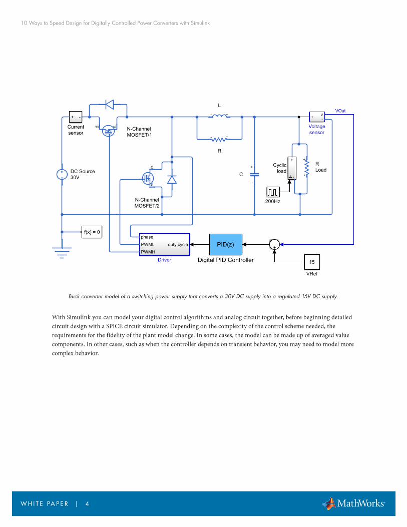
Buck converter model of a switching power supply that converts a 30V DC supply into a regulated 15V DC supply.
With Simulink you can model your digital control algorithms and analog circuit together, before beginning detailed circuit design with a SPICE circuit simulator. Depending on the complexity of the control scheme needed, the requirements for the fidelity of the plant model change. In some cases, the model can be made up of averaged value components. In other cases, such as when the controller depends on transient behavior, you may need to model more complex behavior.
v+ -Voltagesensor
f(x) = 0
C
R
N-ChannelMOSFET/2
N-ChannelMOSFET/1
L
duty cycle
phase
PWML
PWMH
Driver
+ -
Currentsensor
DC Source30V
PID(z)
Digital PID Controller
RLoad
I- -+
Cyclicload
15
VRef
200Hz
VOut
10 Ways to Speed Design for Digitally Controlled Power Converters with Simulink
W H I T E PA P E R | 5
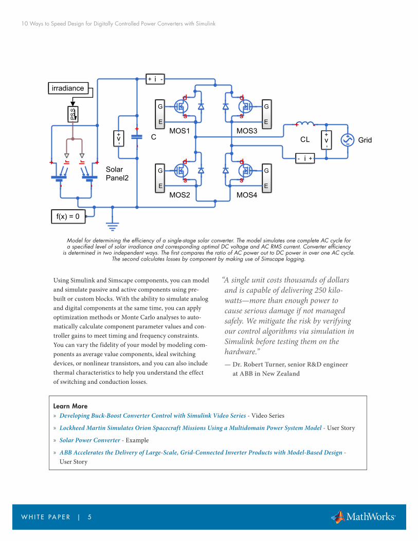
Model for determining the efficiency of a single-stage solar converter. The model simulates one complete AC cycle for a specified level of solar irradiance and corresponding optimal DC voltage and AC RMS current. Converter efficiency
is determined in two independent ways. The first compares the ratio of AC power out to DC power in over one AC cycle. The second calculates losses by component by making use of Simscape logging.
Using Simulink and Simscape components, you can model and simulate passive and active components using pre-built or custom blocks. With the ability to simulate analog and digital components at the same time, you can apply optimization methods or Monte Carlo analyses to auto-matically calculate component parameter values and con-troller gains to meet timing and frequency constraints. You can vary the fidelity of your model by modeling com-ponents as average value components, ideal switching devices, or nonlinear transistors, and you can also include thermal characteristics to help you understand the effect of switching and conduction losses.
Learn More » Developing Buck-Boost Converter Control with Simulink Video Series - Video Series
» Lockheed Martin Simulates Orion Spacecraft Missions Using a Multidomain Power System Model - User Story
» Solar Power Converter - Example
» ABB Accelerates the Delivery of Large-Scale, Grid-Connected Inverter Products with Model-Based Design - User Story
“A single unit costs thousands of dollars and is capable of delivering 250 kilo-watts—more than enough power to cause serious damage if not managed safely. We mitigate the risk by verifying our control algorithms via simulation in Simulink before testing them on the hardware.”— Dr. Robert Turner, senior R&D engineer
at ABB in New Zealand
d
ss
d
MOS3
d
ss
d
MOS1
f(x) = 0
Ir+--
+ Ir Ir +--
+Ir
SolarPanel2
SP
S
Grid+
--+
C
i- +
v -+
G
E
i -+
v
-+
G
E
G
E
G
E
+ --+
CL
irradiance
d
ss
d
MOS2
d
ss
d
MOS4
10 Ways to Speed Design for Digitally Controlled Power Converters with Simulink
W H I T E PA P E R | 6
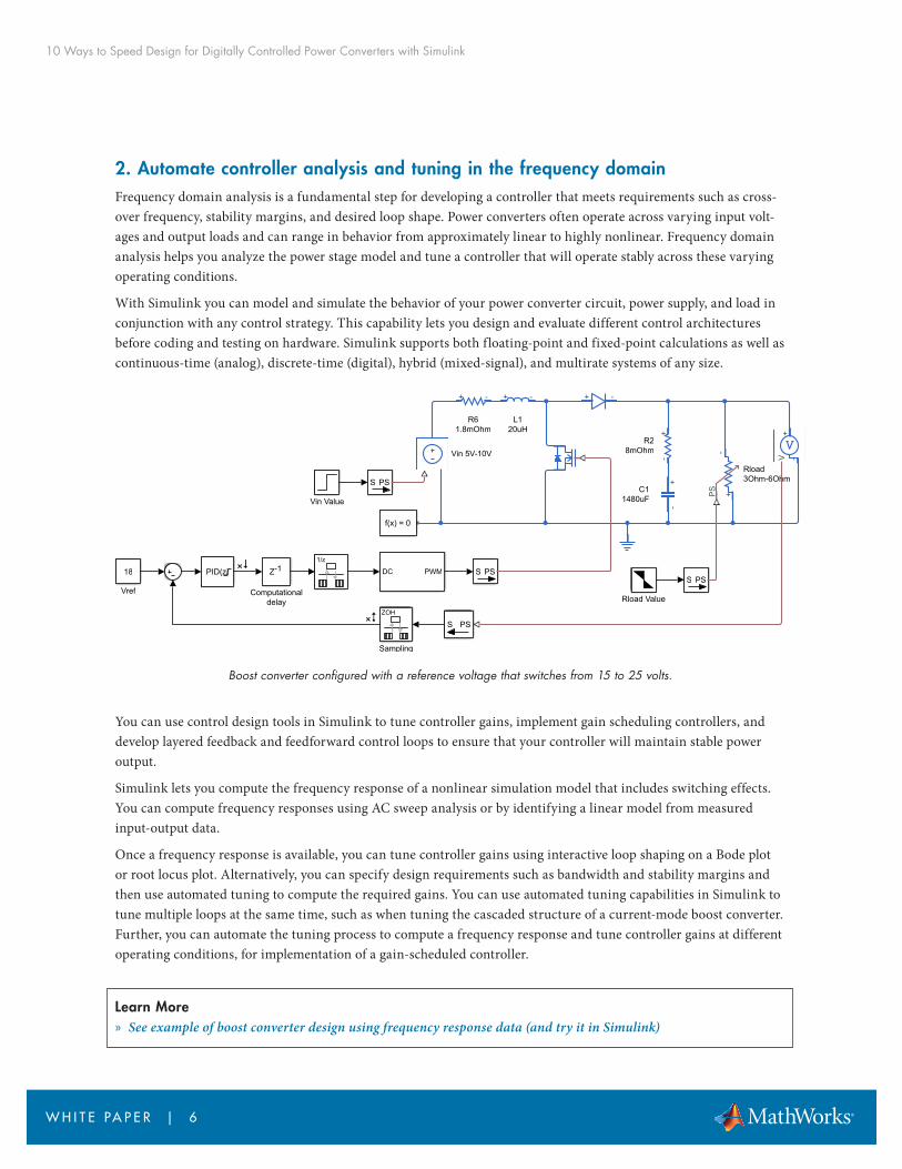
2. Automate controller analysis and tuning in the frequency domainFrequency domain analysis is a fundamental step for developing a controller that meets requirements such as cross-over frequency, stability margins, and desired loop shape. Power converters often operate across varying input volt-ages and output loads and can range in behavior from approximately linear to highly nonlinear. Frequency domain analysis helps you analyze the power stage model and tune a controller that will operate stably across these varying operating conditions.
With Simulink you can model and simulate the behavior of your power converter circuit, power supply, and load in conjunction with any control strategy. This capability lets you design and evaluate different control architectures before coding and testing on hardware. Simulink supports both floating-point and fixed-point calculations as well as continuous-time (analog), discrete-time (digital), hybrid (mixed-signal), and multirate systems of any size.
Boost converter configured with a reference voltage that switches from 15 to 25 volts.
You can use control design tools in Simulink to tune controller gains, implement gain scheduling controllers, and develop layered feedback and feedforward control loops to ensure that your controller will maintain stable power output.
Simulink lets you compute the frequency response of a nonlinear simulation model that includes switching effects. You can compute frequency responses using AC sweep analysis or by identifying a linear model from measured input-output data.
Once a frequency response is available, you can tune controller gains using interactive loop shaping on a Bode plot or root locus plot. Alternatively, you can specify design requirements such as bandwidth and stability margins and then use automated tuning to compute the required gains. You can use automated tuning capabilities in Simulink to tune multiple loops at the same time, such as when tuning the cascaded structure of a current-mode boost converter. Further, you can automate the tuning process to compute a frequency response and tune controller gains at different operating conditions, for implementation of a gain-scheduled controller.
Learn More » See example of boost converter design using frequency response data (and try it in Simulink)
18
Vref
PID(z) Z-1
Computationaldelay
Sampling
DC PWM
Vin Value
Rload Value
L120uH
f(x) = 0
S PS
C11480uF
R61.8mOhm
R28mOhm
S PS
Vin 5V-10V
S PSRload3Ohm-6Ohm
S PS
10 Ways to Speed Design for Digitally Controlled Power Converters with Simulink
W H I T E PA P E R | 7
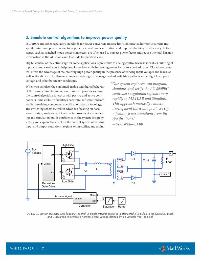
3. Simulate control algorithms to improve power quality IEC 61000 and other regulatory standards for power converters impose limits on injected harmonic current and specify minimum power factors to help increase real power utilization and improve electric grid efficiency. Active stages, such as switched mode power converters, are often used to correct power factor and reduce the total harmon-ic distortion at the AC mains and load side to specified levels.
Digital control of the active stage for some applications is preferable to analog control because it enables tailoring of input current waveforms to help keep losses low while improving power factor to a desired value. Closed-loop con-trol offers the advantage of maintaining high power quality in the presence of varying input voltages and loads, as well as the ability to implement complex mode logic to manage desired switching patterns under light load, peak voltage, and other boundary conditions.
When you simulate the combined analog and digital behavior of the power converter in one environment, you can see how the control algorithm interacts with passive and active com-ponents. This visibility facilitates hardware-software tradeoff studies involving component specification, circuit topology, and switching schemes, well in advance of testing on hard-ware. Design, analysis, and iterative improvement via model-ing and simulation builds confidence in the system design by letting you explore the effect on the control system of varying input and output conditions, regions of instability, and faults.
DC-DC LLC power converter with frequency control. A simple integral control is implemented in Simulink in the Controller block, and is designed to achieve a nominal output voltage defined by the variable Vout_nominal.
“Our system engineers can program, simulate, and verify the AC 800PEC controller’s regulation software very rapidly in MATLAB and Simulink. This approach markedly reduces development times and produces sig-nificantly fewer deviations from the specifications.”— Fritz Wittwer, ABB
gd
s
High Side
v
Meas
Reff control
Controller
Control
gH
gL
BehavioralGate Driver
f(x) = 0
+--
+ BusVoltage
+ --+
Cr
+ --+
Lr
1+
1-
2+
2-
3+
3-3-
3+
2-
2+
1-
1+
Tr
D1
D2
+--
+
Cout+
--+ R
Load
gd
s
Low Side
RampSaturation
f-control signal
10 Ways to Speed Design for Digitally Controlled Power Converters with Simulink
W H I T E PA P E R | 8
The model above contains two variants for the power electronic switches. The detailed version includes a MOSFET with nonlinear characteristics. The abstract version uses a piecewise linear model with an ideal switch, body diode, and output capacitance. The abstract version provides very similar behavior and quicker simulation.
By modeling your control algorithms, electronic components, power supplies, and loads in Simulink, you can com-bine digital control tasks with analog device simulations to explore different control strategies and circuit topologies while analyzing power quality across the entire operating space of the power converter. Simulating and tuning the controller over a range of varying input and output conditions enables you to increase the probability that your design will behave as intended when hardware testing begins, thereby minimizing hardware iterations.
Learn More » ABB Accelerates Application Control Software Development for a Power Electronic Controller - User Story
4. Verify fault-detection, mode logic, and supervisory control across operating conditionsSupervisory and fault detection software protects a power convert-er from a range of faults and abnormal operating conditions. It is often impractical or unsafe to validate this software by testing the power converter for all possible operating ranges and fault condi-tions, and such tests risk damaging expensive test systems. Likewise, if you rely solely on code testing tools, you may miss fault conditions if your test scenarios do not achieve 100% code coverage.
Simulink enables you to model and simulate your control strategy and the passive and active components balance of electronics in your power converter. Using the model, you can vary source voltages, adjust load currents, and create faults of any component to verify the control strategy before proceeding to hardware testing.
Within Simulink and Stateflow®, you can develop and simulate state and supervisory logic in state transition dia-grams, flow charts, state transition tables, and truth tables to model how your converter reacts to events, time-based conditions, and external input signals. This graphical approach lets you avoid writing, analyzing, and debugging complex nested conditional and Boolean expressions.
“Superstates in Stateflow were particularly helpful for fault han-dling. When we had a fault in a substate, we drew a line out of the superstate, and Stateflow ensured that it was always han-dled correctly.”— Han Geerligs, Alstom
10 Ways to Speed Design for Digitally Controlled Power Converters with Simulink
W H I T E PA P E R | 9
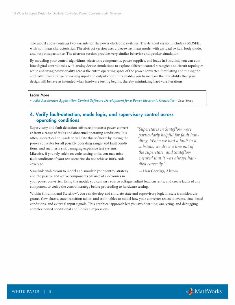
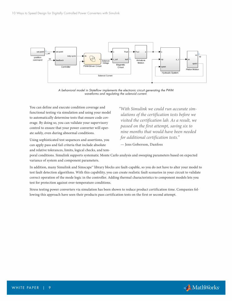
A behavioral model in Stateflow implements the electronic circuit generating the PWM waveforms and regulating the solenoid current.
You can define and execute condition coverage and functional testing via simulation and using your model to automatically determine tests that ensure code cov-erage. By doing so, you can validate your supervisory control to ensure that your power converter will oper-ate safely, even during abnormal conditions.
Using sophisticated test sequences and assertions, you can apply pass and fail criteria that include absolute and relative tolerances, limits, logical checks, and tem-poral conditions. Simulink supports systematic Monte Carlo analysis and sweeping parameters based on expected variance of system and component parameters.
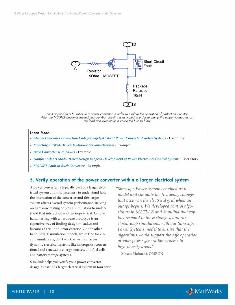
In addition, many Simulink and Simscape™ library blocks are fault-capable, so you do not have to alter your model to test fault detection algorithms. With this capability, you can create realistic fault scenarios in your circuit to validate correct operation of the mode logic in the controller. Adding thermal characteristics to component models lets you test for protection against over-temperature conditions.
Stress testing power converters via simulation has been shown to reduce product certification time. Companies fol-lowing this approach have seen their products pass certification tests on the first or second attempt.
“With Simulink we could run accurate sim-ulations of the certification tests before we visited the certification lab. As a result, we passed on the first attempt, saving six to nine months that would have been needed for additional certification tests.”— Jens Goberson, Danfoss
10 Ways to Speed Design for Digitally Controlled Power Converters with Simulink
W H I T E PA P E R | 1 0
Fault applied to a MOSFET in a power converter in order to explore the operation of protection circuitry. After the MOSFET becomes faulted, the crowbar circuitry is activated in order to clamp the output voltage across
the load and eventually to cause the fuse to blow.
Learn More » Alstom Generates Production Code for Safety-Critical Power Converter Control Systems - User Story
» Modeling a PWM-Driven Hydraulic Servomechanism - Example
» Buck Converter with Faults - Example
» Danfoss Adopts Model-Based Design to Speed Development of Power Electronics Control Systems - User Story
» MOFSET Fault in Buck Converter - Example
5. Verify operation of the power converter within a larger electrical systemA power converter is typically part of a larger elec-trical system and it is necessary to understand how the interaction of the converter and this larger system affects overall system performance. Relying on hardware testing or SPICE simulation to under-stand that interaction is often impractical. On one hand, testing with a hardware prototype is an expensive way of finding design mistakes and becomes a trial-and-error exercise. On the other hand, SPICE simulation models, while fine for cir-cuit simulations, don’t work as well for larger dynamic electrical systems like microgrids, conven-tional and renewable energy sources, and fuel cells and battery storage systems.
Simulink helps you verify your power converter design as part of a larger electrical system in four ways.
d
ss
d
MOSFET
+--
+ PackageParasitic10nH
+ F- XX
F-
+ Short-CircuitFault
1 D
2G
3 S
+ --+
Resistor5Ohm
“Simscape Power Systems enabled us to model and simulate the frequency changes that occur on the electrical grid when an outage begins. We developed control algo-rithms in MATLAB and Simulink that rap-idly respond to these changes, and ran closed-loop simulations with our Simscape Power Systems model to ensure that the algorithms would support the safe operation of solar power generation systems in high-density areas.”—Masao Mabuchi, OMRON
10 Ways to Speed Design for Digitally Controlled Power Converters with Simulink
W H I T E PA P E R | 1 1
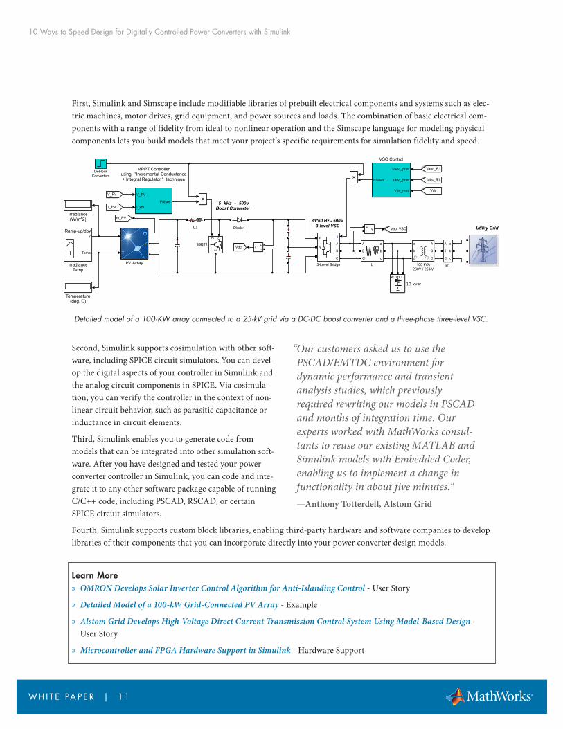
First, Simulink and Simscape include modifiable libraries of prebuilt electrical components and systems such as elec-tric machines, motor drives, grid equipment, and power sources and loads. The combination of basic electrical com-ponents with a range of fidelity from ideal to nonlinear operation and the Simscape language for modeling physical components lets you build models that meet your project’s specific requirements for simulation fidelity and speed.
Detailed model of a 100-KW array connected to a 25-kV grid via a DC-DC boost converter and a three-phase three-level VSC.
Second, Simulink supports cosimulation with other soft-ware, including SPICE circuit simulators. You can devel-op the digital aspects of your controller in Simulink and the analog circuit components in SPICE. Via cosimula-tion, you can verify the controller in the context of non-linear circuit behavior, such as parasitic capacitance or inductance in circuit elements.
Third, Simulink enables you to generate code from models that can be integrated into other simulation soft-ware. After you have designed and tested your power converter controller in Simulink, you can code and inte-grate it to any other software package capable of running C/C++ code, including PSCAD, RSCAD, or certain SPICE circuit simulators.
Fourth, Simulink supports custom block libraries, enabling third-party hardware and software companies to develop libraries of their components that you can incorporate directly into your power converter design models.
Learn More » OMRON Develops Solar Inverter Control Algorithm for Anti-Islanding Control - User Story
» Detailed Model of a 100-kW Grid-Connected PV Array - Example
» Alstom Grid Develops High-Voltage Direct Current Transmission Control System Using Model-Based Design - User Story
» Microcontroller and FPGA Hardware Support in Simulink - Hardware Support
Utility Grid33*60 Hz - 500V
3-level VSC
5 kHz - 500VBoost Converter
v+-
v +-
Vabc_prim
Iabc_prim
Vdc_mes
Pulses
VSC Control
a
b
c
A
B
C
L
Ir
Temp
Ramp-up/down Irradiance
IrradianceTemp
Iabc_B1
V_PV
Vabc_B1
I_PV
+
++
V_PV
I_PVPulses
MPPT Controllerusing "Incremental Conductance+ Integral Regulator " technique
A
B
C
a
b
c
B1
g
A
B
C
+
N
-
3-Level Bridge
A
B
C
a
b
c YgD1
100 kVA260V / 25 kV
A B C
10 kvar
DeblockConverters
+
L1
Vdc
Vab_VSC
m_PV
Vdc
g CE
IGBT1
Diode1
Irradiance(W/m^2)
Temperature(deg. C)
Ir
T
mm
+
-
PV Array
“Our customers asked us to use the PSCAD/EMTDC environment for dynamic performance and transient analysis studies, which previously required rewriting our models in PSCAD and months of integration time. Our experts worked with MathWorks consul-tants to reuse our existing MATLAB and Simulink models with Embedded Coder, enabling us to implement a change in functionality in about five minutes.”—Anthony Totterdell, Alstom Grid
10 Ways to Speed Design for Digitally Controlled Power Converters with Simulink
W H I T E PA P E R | 1 2
6. Validate control code on the processor without damaging electrical system hardwareAt some point in your project, you will be ready to test your control code for the first time in the hardware system. If the code has errors and does not behave as intended, it will need to be corrected. If the errors are severe enough, you may have to replace hardware damaged during the test.
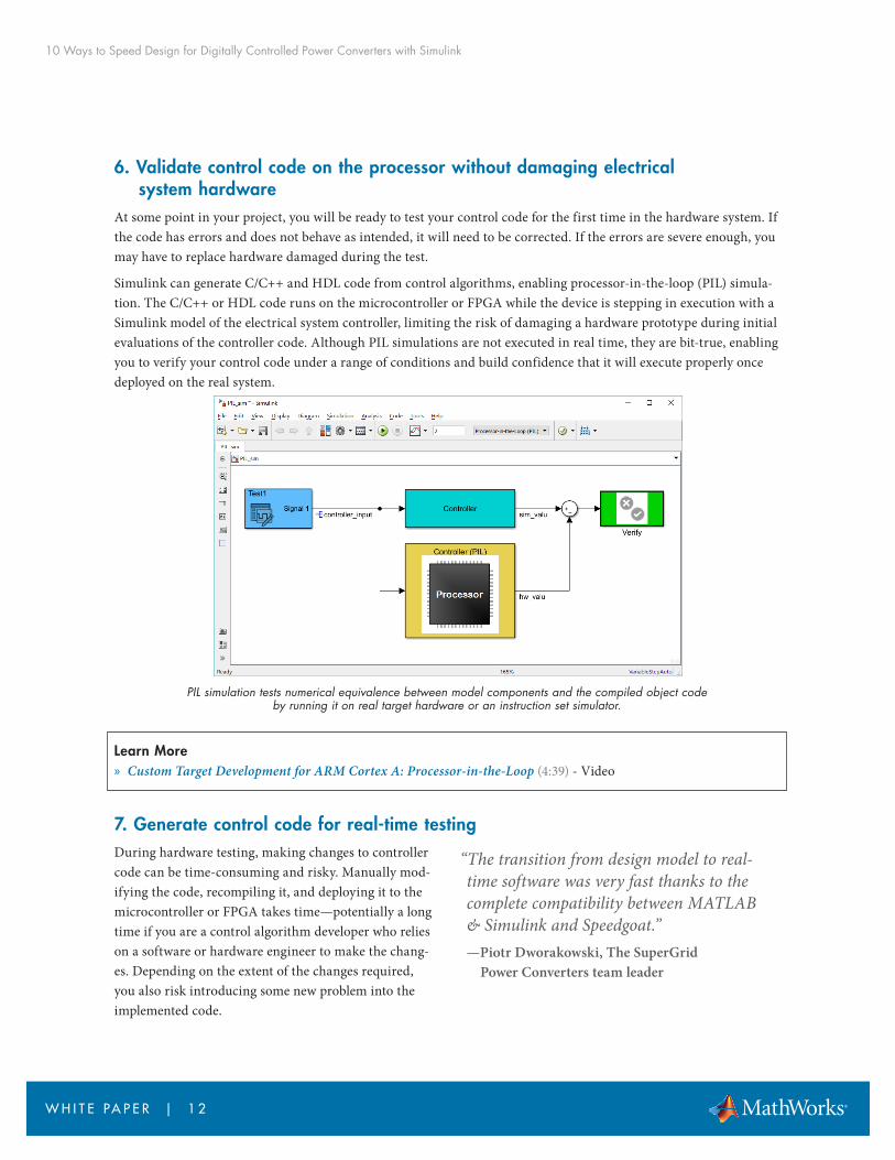
Simulink can generate C/C++ and HDL code from control algorithms, enabling processor-in-the-loop (PIL) simula-tion. The C/C++ or HDL code runs on the microcontroller or FPGA while the device is stepping in execution with a Simulink model of the electrical system controller, limiting the risk of damaging a hardware prototype during initial evaluations of the controller code. Although PIL simulations are not executed in real time, they are bit-true, enabling you to verify your control code under a range of conditions and build confidence that it will execute properly once deployed on the real system.
PIL simulation tests numerical equivalence between model components and the compiled object code by running it on real target hardware or an instruction set simulator.
Learn More » Custom Target Development for ARM Cortex A: Processor-in-the-Loop (4:39) - Video
7. Generate control code for real-time testingDuring hardware testing, making changes to controller code can be time-consuming and risky. Manually mod-ifying the code, recompiling it, and deploying it to the microcontroller or FPGA takes time—potentially a long time if you are a control algorithm developer who relies on a software or hardware engineer to make the chang-es. Depending on the extent of the changes required, you also risk introducing some new problem into the implemented code.
“The transition from design model to real-time software was very fast thanks to the complete compatibility between MATLAB & Simulink and Speedgoat.”—Piotr Dworakowski, The SuperGrid
Power Converters team leader
10 Ways to Speed Design for Digitally Controlled Power Converters with Simulink
W H I T E PA P E R | 1 3
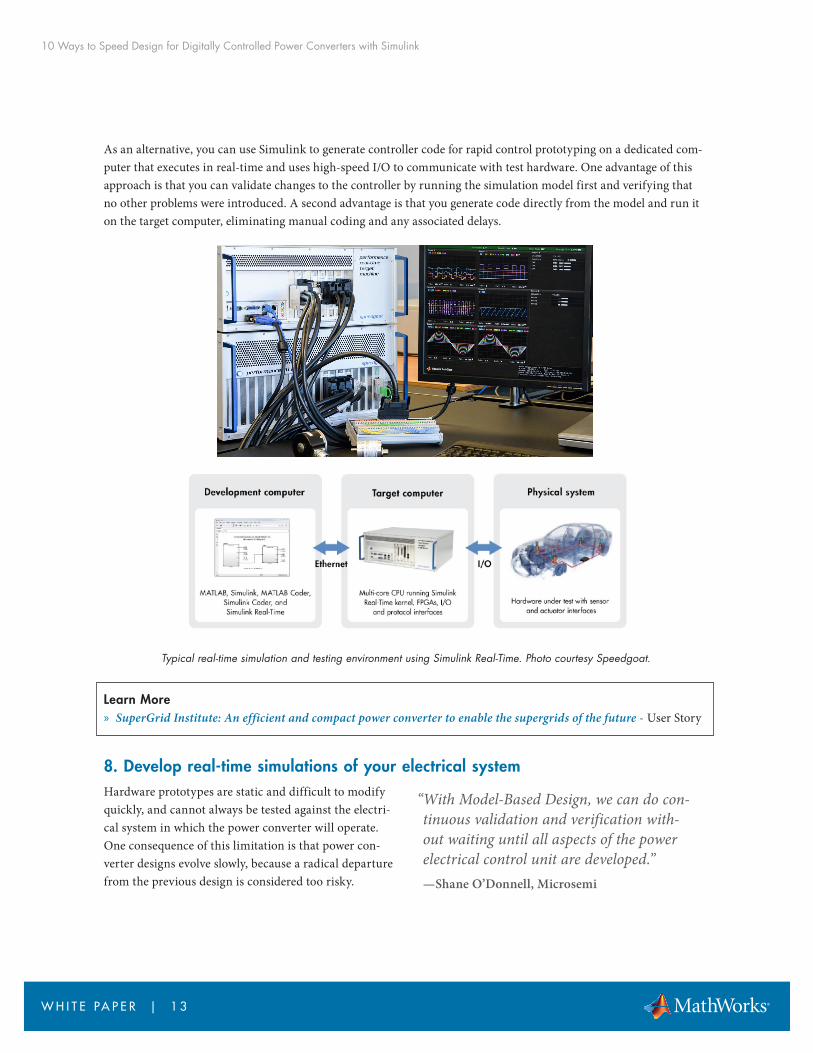
As an alternative, you can use Simulink to generate controller code for rapid control prototyping on a dedicated com-puter that executes in real-time and uses high-speed I/O to communicate with test hardware. One advantage of this approach is that you can validate changes to the controller by running the simulation model first and verifying that no other problems were introduced. A second advantage is that you generate code directly from the model and run it on the target computer, eliminating manual coding and any associated delays.
Typical real-time simulation and testing environment using Simulink Real-Time. Photo courtesy Speedgoat.
Learn More » SuperGrid Institute: An efficient and compact power converter to enable the supergrids of the future - User Story
8. Develop real-time simulations of your electrical systemHardware prototypes are static and difficult to modify quickly, and cannot always be tested against the electri-cal system in which the power converter will operate. One consequence of this limitation is that power con-verter designs evolve slowly, because a radical departure from the previous design is considered too risky.
“With Model-Based Design, we can do con-tinuous validation and verification with-out waiting until all aspects of the power electrical control unit are developed.”—Shane O’Donnell, Microsemi

10 Ways to Speed Design for Digitally Controlled Power Converters with Simulink
W H I T E PA P E R | 1 4
Simulink can generate C/C++ and HDL code from the simulation model of the hardware in your power converter and the system of which it is part, including the supply and the load. This capability lets you run a real-time simula-tion of the hardware, often called hardware-in-the-loop (HiL) simulation, to test the real-time execution of your con-troller code before verifying it in a hardware prototype. As a result, you can find and correct errors before they potentially damage expensive and difficult-to-replace prototype hardware. Further, you can test the control code via real-time simulation in the electrical system that contains the power converter.
Learn More » Developing a Real-Time Motor Model for HIL Testing (22:26) - Video
» Real-Time Simulation and Testing of Power Electronics on a More Electric Aircraft - Article
9. Generate code for microcontrollers, FPGAs, or ASICs from your modelIf you forgo simulation and opt to proceed directly from your control algorithm to handwriting C/C++ or HDL code you risk introducing errors that show up only during hardware-software integration testing, when diagnosing and resolving the errors are likely to cause project delays.
First, you can’t validate that your algorithm will do what is intended until hardware tests, so you won’t know if errors that are detected during these tests stem from the control algorithm itself or from other factors. Second, manually coding the algorithm may introduce translation or interpretation errors.
You can avoid these issues by generating code directly from your controller models after validating them via simulation in Simulink. You can generate optimized and stable C/C++ code for implementation on micro-controllers or synthesizable HDL code for FPGA pro-gramming or ASIC prototyping. Automatic code generation eliminates manual algorithm translation errors and produces C/C++ and HDL code with numer-ical equivalence to the algorithms you have validated in Simulink. By simulating your control algorithms over all possible operating and fault conditions, you increase confidence that the generated code will handle those same conditions in the real system, even if you are not able to test for all of them. If hardware tests later
“With Model-Based Design, our developer productivity is easily increased tenfold. Simulation and code generation enable us to turn changes around quickly and elimi-nate human errors in coding. Our algo-rithms typically work the first time, so we no longer waste a big part of our develop-ment cycle debugging code.”—Dr. Robert Turner,
senior R&D engineer at ABB
“Simulink helps system architects and hardware designers communicate. It is like a shared language that enables us to exchange knowledge, ideas, and designs. Simulink and HDL Coder enable us to focus on developing our algorithms and refining our design via simulation, not on checking VHDL syntax and coding rules.”—Marcel van Bakel, Philips Healthcare

10 Ways to Speed Design for Digitally Controlled Power Converters with Simulink
W H I T E PA P E R | 1 5
© 2018 The MathWorks, Inc. MATLAB and Simulink are registered trademarks of The MathWorks, Inc. See mathworks.com/trademarks for a list of additional trademarks. Other product or brand names may be trademarks or registered trademarks of their respective holders.
indicate that algorithm changes are needed, you can simply modify the algorithms in your simulation model, rerun simulation test cases to verify the correctness of the algorithm changes, and generate the new, updated code. All gen-erated C/C++ and HDL code is fully portable, optimizable with a range of options, and bidirectionally traceable to the Simulink model.
Learn More » Implementing a Buck Converter Controller Using Embedded Coder (34:01) - Video
» ABB Accelerates the Delivery of Large-Scale, Grid-Connected Inverter Products with Model-Based Design - User Story
» Philips Healthcare Develops Smart Digital RF Power Subsystem for MRI Systems - User Story
10. Reuse handwritten code from existing projects It’s possible, or perhaps likely, that your next power converter design will incorporate aspects of a previous generation. This is true of circuitry and code, if you are using digital control. At times, however, the handwrit-ten legacy code you’d like to reuse or modify is not well documented or the colleagues who contributed to its development are no longer available to consult. The uncertainty about the existing code may lead you to reject it even though it may be perfectly suited for your project. This leaves no option but to develop new code, forgoing the time and costs savings that reuse would provide.
With Simulink, you can integrate existing hand-coded C/C++ functions, such as device drivers, lookup tables, and general functions and interfaces, into the model of your new design. You can then simulate the legacy code with the new functionality you’ve developed in Simulink across a complete range of operating conditions and make any nec-essary changes to ensure existing code works seamlessly within the new design.
Learn More » Integrate C Functions Using the Legacy Code Tool - Documentation
» Lotus Engineering Develops Control Systems Software to Reduce Diesel Emissions - User Story
Next StepsTake the next step to speed your power converter control project.
Explore: Power Electronics Control Design with Simulink
Download: Trial Software for Power Electronics Control
Get Started: Consulting Services
“I integrated legacy code into the model, so I knew I was simulating with the real algorithms. Those same algorithms were also called very neatly by the generated code”—Roger Tudor, Lotus Engineering