10 things you need to know about ir windows iriss
TRANSCRIPT

10 Things You Need To Know
About Infrared Windows

10 Things You Need To Know About Infrared Windows
Foreword .................................................................................................................................................................................................................................ii
1. What is an Infrared Window? ............................................................................................................................................................................. 1
2. Infrared Window Lens Materials ..................................................................................................................................................................... 3
3. The Importance of Emissivity in Electrical Thermography .......................................................................................................... 7
4. Know Your IR Window Transmission ......................................................................................................................................................... 11
5. Field of View (FOV) Through an Infrared Window .......................................................................................................................... 16
6. Proper Installation of an Infrared Window ........................................................................................................................................... 20
7. Certifications and Standards .......................................................................................................................................................................... 25
8. Arc Flash, NFPA & OSHA: Implications on Infrared Inspections ............................................................................................ 29
9. Infrared Window Program Benefits ........................................................................................................................................................... 32
10. Infrared Window Cost-Benefit Analysis ............................................................................................................................................... 35
Chapter List
i | iriss.com
Copyright ©2009 by IRISS, inc. All rights reserved
“Knowledge comes by eyes always open and working hands; and there is no knowledge that is not power.” - Ralph Waldo Emerson 1803-1882
To Our Valued Clients:My goal is that this book will clarify a handful of the key points that are at the heart of most questions about infrared windows—their use and limitations.
The use of infrared (IR) inspection windows in industrial applications has grown exponentially over the past five years. Much of the recent acceptance has coincided with the increase in the level of awareness regarding electrical safety and risk reduction. Organizations such as OSHA, NFPA, CSA, IEEE, ANSI and NETA have been at the vanguard of this movement.
The use of IR windows to facilitate safer, more efficient inspection of energized electrical equipment has outpaced the infrared industry in general. Today, switchgear manufacturers regularly install IR windows at the point-of-manufacture. This, in turn, has generated additional impetus for firms to retrofit existing equipment.
As the use, and application, of IR windows continues to gain acceptance, the diversity of applications will continue to prompt an even wider range of questions. However, most relate to just a few core concepts. I present these tips and technical details not just as a manufacturer who understands the engineering and scientific issues pertaining to IR windows; I also bring my practical knowledge as a Level III thermographer with over 15 years of industry experience. It is my end-user perspective that makes IRISS unique in the industry; and it is our focus on this perspective that is reflected in all our product designs and product development. Our company, our products and this guide are all based on practical, real world experience that has been honed with input from clients, staff and through countless hours of personally architecting successful IR window programs for companies around the globe.
I am proud that IRISS is making thermography safer and more accurate. By their very nature, IRISS products are simply “Safer by Design”.
Martin RobinsonLevel III ThermographerPresident & Chief EngineerIRISS, Inc.
Foreword
iriss.com | ii

10 Things You Need To Know About Infrared Windows
What is an Infrared Inspection Window?
Definition:A window is used to separate environments of differing pressures or temperatures, while allowing energy at a specified electromagnetic wavelength to pass between the two environments.
An infrared window (also referred to as a viewport, viewing pane, sightglass, port or grill) is a generic term used to describe an inspection point that is designed to allow infrared radiation to transmit to the outside environment. Simply put, an infrared (IR) window is a data collection point for a thermal camera. All IR windows must fulfill the strength, rigidity and environmental requirements of the type of equipment into which it is installed. It must also be compatible with the infrared equipment being used.
Some IR windows are simply a housing with an open center, and a cover that secures the opening. Typically, the IR window housing will contain a grill or an optic. The design, size, and material used are driven by considerations such as the required field-of-view, camera lens compatibility, intended environment, sealing requirements, and safety considerations.
Infrared Window Classification:Let’s explore the specific types of infrared windows:
Viewing PanesA viewing pane is an IR window that has a lens secured in the housing. Because the lens forms a seal between the internal/external environments, the thermographer is not directly exposed to energized components (as per NFPA 70E/CSA Z462 definitions of “enclosed” and “guarded”). This usually means that elevated levels of Personal Protective Equipment (PPE) are not required.
Inspection GrillsAn inspection grill is an infrared window containing a grill or “mesh” in place of a solid optic. Grills are primarily used in mechanical applications for machinery guards, or in instances where operators wish to complete infrared and ultrasound inspections from the same access point. As the name implies, when opened, a grill does not maintain an IP65/NEMA 4 seal; instead, it is a collection of small openings intended to keep fingers and tools from breaking the plane of the cabinet. It is important to understand that a grill will not maintain an enclosed state for electrical equipment since it allows the environment of the energized components to change. Therefore, they would not maintain an “enclosed” condition per NFPA 70E/CSA Z462, and as such, elevated PPE levels are required per NFPA 70E/ CSA Z462 mandates.
Chapter 1
1 | iriss.com

Copyright ©2009 by IRISS, inc. All rights reserved
Inspection PortsInfrared inspection ports are usually no more than 15mm in diameter (IP2X). Ports can contain either specialty lenses or adaptors. They can be open (as with grills) or sealed with a lens (as with viewing panes). It is essential that the thermogra-pher understand whether the port is open or sealed – this will determine whether the electrical equipment is in an “enclosed” and “guarded” condition, which will dictate PPE requirements.
Custom SolutionsCertain applications may require a custom solution: perhaps metal cladding obstructs access to bus joints, or maybe multiple connections are positioned just behind a dead-front panel of a PDU or MCC. In these cases, standard IR windows may be impracticable – or cost prohibitive. Depending on the requirement, it is possible to design custom windows to allow inspection of applications that may have been previously “un-inspectable” due to high incident energy levels. (Note: decisions regarding custom solutions should always involve corporate safety officials.)
Environmental RatingsIngress protection and environmental integrity standards rate the suitability of a component to resist a wet or dusty environment. The two primary ingress protection standards that apply to electrical components are Ingress Protection (IP) and National Electrical Manufacturers Association (NEMA) standards. (Ingress protection standards are discussed in greater depth in Chapter 7.)
When installing an IR window, it is standard practice to ensure that the IP/NEMA rating of the window is equal to, or greater than, that of the enclosure.
Summary1. “Infrared window” is a generic term – there are actually several different categories of infrared windows available, all filling a different need.2. If installed on energized electrical equipment, does the window maintain an “enclosed” and “guarded” condition for the cabinet enclosure? Does opening the window mix the outside and inside environments, thereby negating the “enclosed” state?3. PPE requirements may differ dramatically depending upon the type of infrared window system used.4. Always seek, and document, appropriate approvals for any custom modifications.5. Be aware of the environmental ratings on the switchgear. Never install an infrared widow with a rating lower than that of the original enclosure.
Chapter 1 CONT’D
iriss.com | 2
10 Things You Need To Know About Infrared Windows
Infrared Window Lens Materials
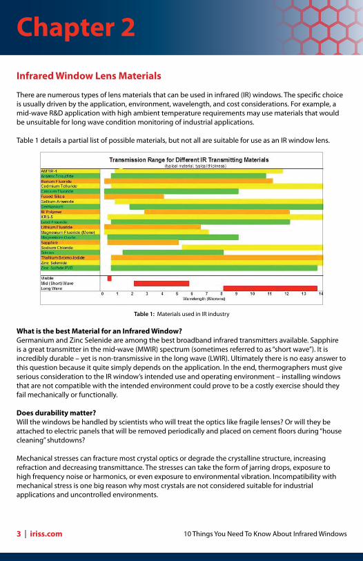
There are numerous types of lens materials that can be used in infrared (IR) windows. The specific choice is usually driven by the application, environment, wavelength, and cost considerations. For example, a mid-wave R&D application with high ambient temperature requirements may use materials that would be unsuitable for long wave condition monitoring of industrial applications.
Table 1 details a partial list of possible materials, but not all are suitable for use as an IR window lens.
What is the best Material for an Infrared Window?Germanium and Zinc Selenide are among the best broadband infrared transmitters available. Sapphire is a great transmitter in the mid-wave (MWIR) spectrum (sometimes referred to as “short wave”). It is incredibly durable – yet is non-transmissive in the long wave (LWIR). Ultimately there is no easy answer to this question because it quite simply depends on the application. In the end, thermographers must give serious consideration to the IR window’s intended use and operating environment – installing windows that are not compatible with the intended environment could prove to be a costly exercise should they fail mechanically or functionally.
Does durability matter?Will the windows be handled by scientists who will treat the optics like fragile lenses? Or will they be attached to electric panels that will be removed periodically and placed on cement floors during “house cleaning” shutdowns?
Mechanical stresses can fracture most crystal optics or degrade the crystalline structure, increasing refraction and decreasing transmittance. The stresses can take the form of jarring drops, exposure to high frequency noise or harmonics, or even exposure to environmental vibration. Incompatibility with mechanical stress is one big reason why most crystals are not considered suitable for industrial applications and uncontrolled environments.
Table 1: Materials used in IR industry
Chapter 2
3 | iriss.com
Copyright ©2009 by IRISS, inc. All rights reserved
What are the environmental factors?Will the windows be used in a controlled laboratory environment, or will they be installed in a factory setting or an outdoor substation?
All materials have an Achilles’ heel. Polymers would not be the answer in a kiln application. Likewise, many crystals, such as the Fluoride family, are water soluble (also called “hydroscopic”) even when coated. Because they cannot maintain a stable transmission rate when exposed to humidity, or moisture, these crystals are not suited for use in most industrial applications. Carefully consider the operating environment before choosing an infrared window lens material.
Suitability of Crystal OpticsTraditionally, Fluoride crystals (Calcium Fluoride: CaF2) and (Barium Fluoride: BaF2) were the most commonly used infrared window optic materials. However, when Barium Fluoride was classified as a carcinogen, CaF2became primary option.
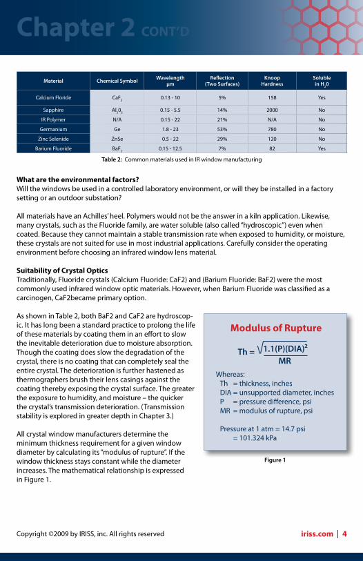
As shown in Table 2, both BaF2 and CaF2 are hydroscop-ic. It has long been a standard practice to prolong the life of these materials by coating them in an effort to slow the inevitable deterioration due to moisture absorption. Though the coating does slow the degradation of the crystal, there is no coating that can completely seal the entire crystal. The deterioration is further hastened as thermographers brush their lens casings against the coating thereby exposing the crystal surface. The greater the exposure to humidity, and moisture – the quicker the crystal’s transmission deterioration. (Transmission stability is explored in greater depth in Chapter 3.)
All crystal window manufacturers determine the minimum thickness requirement for a given window diameter by calculating its “modulus of rupture”. If the window thickness stays constant while the diameter increases. The mathematical relationship is expressed in Figure 1.
Modulus of Rupture
Whereas: Th = thickness, inches DIA = unsupported diameter, inches P = pressure difference, psi MR = modulus of rupture, psi
Pressure at 1 atm = 14.7 psi = 101.324 kPa
Figure 1
Th = MR
1.1(P)(DIA)²
Chapter 2 CONT’D
iriss.com | 4
Material Chemical Symbol Wavelength µm
Reflection (Two Surfaces)
Knoop Hardness
Solublein H20
Calcium Floride CaF2 0.13 - 10 5% 158 Yes
Sapphire Al203 0.15 - 5.5 14% 2000 No
IR Polymer N/A 0.15 - 22 21% N/A No
Germanium Ge 1.8 - 23 53% 780 No
Zinc Selenide ZnSe 0.5 - 22 29% 120 No
Barium Fluoride BaF2 0.15 - 12.5 7% 82 Yes
Table 2: Common materials used in IR window manufacturing
10 Things You Need To Know About Infrared Windows
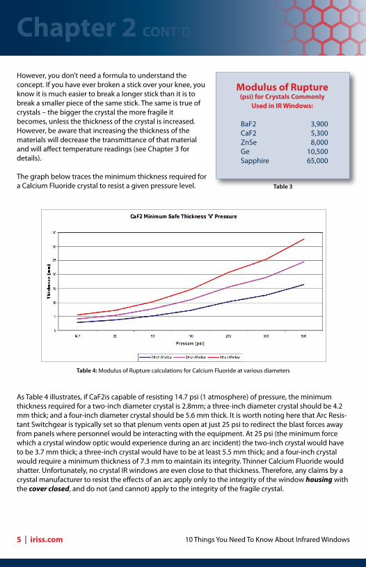
However, you don’t need a formula to understand the concept. If you have ever broken a stick over your knee, you know it is much easier to break a longer stick than it is to break a smaller piece of the same stick. The same is true of crystals – the bigger the crystal the more fragile it becomes, unless the thickness of the crystal is increased. However, be aware that increasing the thickness of the materials will decrease the transmittance of that material and will affect temperature readings (see Chapter 3 for details).
The graph below traces the minimum thickness required for a Calcium Fluoride crystal to resist a given pressure level.
As Table 4 illustrates, if CaF2is capable of resisting 14.7 psi (1 atmosphere) of pressure, the minimum thickness required for a two-inch diameter crystal is 2.8mm; a three-inch diameter crystal should be 4.2 mm thick; and a four-inch diameter crystal should be 5.6 mm thick. It is worth noting here that Arc Resis-tant Switchgear is typically set so that plenum vents open at just 25 psi to redirect the blast forces away from panels where personnel would be interacting with the equipment. At 25 psi (the minimum force which a crystal window optic would experience during an arc incident) the two-inch crystal would have to be 3.7 mm thick; a three-inch crystal would have to be at least 5.5 mm thick; and a four-inch crystal would require a minimum thickness of 7.3 mm to maintain its integrity. Thinner Calcium Fluoride would shatter. Unfortunately, no crystal IR windows are even close to that thickness. Therefore, any claims by a crystal manufacturer to resist the effects of an arc apply only to the integrity of the window housing with the cover closed, and do not (and cannot) apply to the integrity of the fragile crystal.
Table 4: Modulus of Rupture calculations for Calcium Fluoride at various diameters
Modulus of Rupture (psi) for Crystals Commonly
Used in IR Windows:
BaF2 3,900 CaF2 5,300 ZnSe 8,000 Ge 10,500 Sapphire 65,000
Table 3
Chapter 2 CONT’D
5 | iriss.com
Copyright ©2009 by IRISS, inc. All rights reserved
Polymeric Lens MaterialsThe past several years have seen a move toward the use of transmissive polymers as a lens material due to their inherent resiliency and stability. These materials are unaffected by mechanical stress and will suffer no effects on transmittance. They are stable: nonreactive to moisture, humidity, seawater, and a broad spectrum of acids and alkalis – in short, they are well suited to handle the rigors of the industrial environment.
Polymers are also extremely resilient. Because they are malleable, they will tend to absorb impact rather than shatter. When reinforced, with specially engineered grills, the optic is capable of resisting a sustained load. As a result, the only long wave compatible IR window optic capable of passing industry standard impact tests (as will be explored in Chapter 7) is a reinforced polymer optic.
A reinforced polymer optic can maintain a consistent thickness regardless of window diameter because the cells of the reinforcing material remain a consistent diameter. Consistent optic thickness means consistent transmission rate — regardless of window size.
The only applications ill-suited to polymer optics are those in which the ambient temperature (not target temperature) is expected to exceed 200⁰C (392°F). Even so, like all other polymeric materials used on switchgear, polymer windows must meet the same stringent flammability and impact tests as prescribed by UL94. The classifications within UL94 take into consideration: •Sizeandthicknessofthepart •Distancefromun-insulated,liveparts •Hotwireignition •Highcurrentarcignition •Highvoltagearctrackingrate
Summary1. Different materials may react differently to moisture, humidity, chemicals, and mechanical stresses.2. Thermographers must fully consider the environmental factors and operating conditions to sustain accurate readings.3. IR window optics come in a wide variety of transmission rates.4. IR window optics come in a wide range of mechanical strength.5. An IR window should be functional for the life of the panel to which it is affixed. Be sure that warranties apply not only to the workmanship of the window housing, but also apply to the durability and stability of the optic in the proposed environment. For example, IRISS, inc. offers an Unconditional Lifetime Warranty for all its industrial-grade windows.6. Seek advice from IR window manufacturers or lens suppliers before deciding what materials best suit an application.7. Consider working with a vendor that can supply IR windows made of a variety of materials, rather than a “one size fits all” vendor. With an array of windows optics to choose from, it is more likely that any peculiarities in a given application can be addressed with the most appropriate solution.
Chapter 2 CONT’D
iriss.com | 6

10 Things You Need To Know About Infrared Windows
The Importance of Emissivity in Electrical Thermography
A typical factory is full of equipment that requires periodic infrared (IR) inspection. The challenge, as any thermographer knows, is getting an accurate indication of equipment health. Properly compensating for the various emissivity values of all the components one encounters on the factory floor is possibly the most critical factor in performing accurate and meaningful inspections. Even slight errors in emissivity compensation can lead to significant errors in temperature and ΔT (difference in temperature) calculations. Electrical cabinets are a good example, as they may contain materials with emissivity values ranging from 0.07 to 0.95.
The Science of Infrared ThermographyThe electromagnetic spectrum is a continuum made up of cosmic rays, gamma rays, X-rays, ultraviolet light, visible light, infrared radiation, microwaves and radio waves (in order of increasing wavelength and decreasing power). Infrared is that portion of the spectrum between 0.75μm (microns) and 1000μm in wavelength, starting just beyond what the human eye is capable of seeing.
All objects above absolute zero emit infrared radiation. As an object heats up, the intensity of emitted radiation increases exponentially (Stephan-Boltzmann’s Law) and the peak radiation shifts to shorter and shorter wavelengths (Planck’s Law), moving eventually into the visible spectrum. This is why a hot burner will glow red (“incandescent”) after it achieves roughly 500°C (923°F).
Today’s radiometric IR imagers are capable of “seeing” and calculating the emitted radiation from a target object. There are only three sources of this radiation: it can be reflected from other sources; it can be transmitted through the object from a source behind it; or the radiation can be emitted by the object.
Kirchhoff’s LawAn extension of Kirchhoff’s Law tells us that the sum of the radiation leaving the surface of an object equals one: expressed as Watts Emitted + Watts Transmitted + Watts Reflected = 1 (or ε+τ+ρ=1).
Chapter 3
Figure 1
7 | iriss.com
Copyright ©2009 by IRISS, inc. All rights reserved
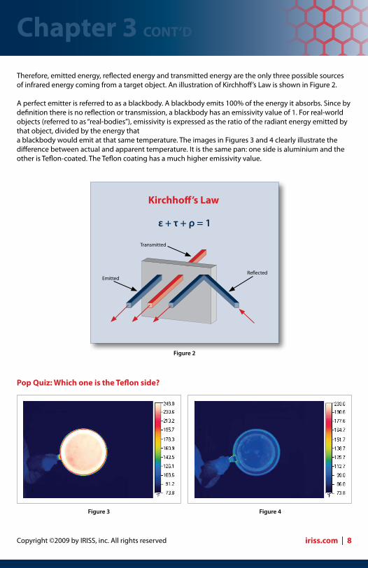
Therefore, emitted energy, reflected energy and transmitted energy are the only three possible sources of infrared energy coming from a target object. An illustration of Kirchhoff’s Law is shown in Figure 2.
A perfect emitter is referred to as a blackbody. A blackbody emits 100% of the energy it absorbs. Since by definition there is no reflection or transmission, a blackbody has an emissivity value of 1. For real-world objects (referred to as “real-bodies”), emissivity is expressed as the ratio of the radiant energy emitted by that object, divided by the energy that a blackbody would emit at that same temperature. The images in Figures 3 and 4 clearly illustrate the difference between actual and apparent temperature. It is the same pan: one side is aluminium and the other is Teflon-coated. The Teflon coating has a much higher emissivity value.
Pop Quiz: Which one is the Teflon side?
Figure 3 Figure 4
Figure 2
Kirchhoff’s Law
ε + τ + ρ = 1
Reflected
Transmitted
Emitted
Chapter 3 CONT’D
iriss.com | 8
10 Things You Need To Know About Infrared Windows
Chart 1
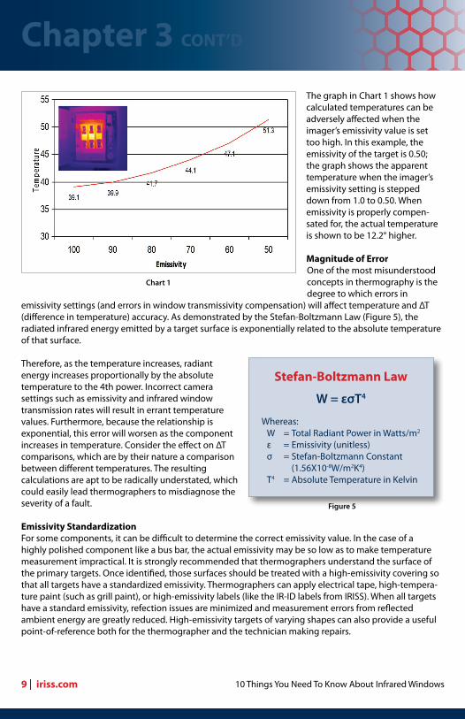
The graph in Chart 1 shows how calculated temperatures can be adversely affected when the imager’s emissivity value is set too high. In this example, the emissivity of the target is 0.50; the graph shows the apparent temperature when the imager’s emissivity setting is stepped down from 1.0 to 0.50. When emissivity is properly compen-sated for, the actual temperature is shown to be 12.2° higher.
Magnitude of ErrorOne of the most misunderstood concepts in thermography is the degree to which errors in
emissivity settings (and errors in window transmissivity compensation) will affect temperature and ΔT (difference in temperature) accuracy. As demonstrated by the Stefan-Boltzmann Law (Figure 5), the radiated infrared energy emitted by a target surface is exponentially related to the absolute temperature of that surface.
Therefore, as the temperature increases, radiant energy increases proportionally by the absolute temperature to the 4th power. Incorrect camera settings such as emissivity and infrared window transmission rates will result in errant temperature values. Furthermore, because the relationship is exponential, this error will worsen as the component increases in temperature. Consider the effect on ΔT comparisons, which are by their nature a comparison between different temperatures. The resulting calculations are apt to be radically understated, which could easily lead thermographers to misdiagnose the severity of a fault.
Emissivity StandardizationFor some components, it can be difficult to determine the correct emissivity value. In the case of a highly polished component like a bus bar, the actual emissivity may be so low as to make temperature measurement impractical. It is strongly recommended that thermographers understand the surface of the primary targets. Once identified, those surfaces should be treated with a high-emissivity covering so that all targets have a standardized emissivity. Thermographers can apply electrical tape, high-tempera-ture paint (such as grill paint), or high-emissivity labels (like the IR-ID labels from IRISS). When all targets have a standard emissivity, refection issues are minimized and measurement errors from reflected ambient energy are greatly reduced. High-emissivity targets of varying shapes can also provide a useful point-of-reference both for the thermographer and the technician making repairs.
Stefan-Boltzmann Law
Whereas: W = Total Radiant Power in Watts/m2
ε = Emissivity (unitless) σ = Stefan-Boltzmann Constant (1.56X10⁻⁸W/m2K4) T4 = Absolute Temperature in Kelvin
Figure 5
W = εσΤ4
Chapter 3 CONT’D
9 | iriss.com

Copyright ©2009 by IRISS, inc. All rights reserved
The image in Figure 6, a thermogram of the interior of a piece of switchgear, appears to show a wide variation in temperature. Can you identify some faults? In reality, this switchgear is new and has never been energized. The differences in shading in the thermogram are all due to reflection issues. The digital photo (Figure 7) shows that the thermographer has placed a piece of electrical tape around one area of the bus bar. The tape in the thermogram shows the true temperature of the reflective bus. The moral of the story: A picture might be worth a thousand words, but a thermogram is not worth the paper it’s printed on unless emissivity is standardized (or Known).
Pop Quiz Answer: The Teflon side is Fig 3. Fig 4 is the stainless steel side which appears cooler than Fig 3 because it is reflecting the cooler background temperatures.
Figure 6 Figure 7
Summary1. Emissivity is one of the most important variables a thermographer must understand.2. Whenever possible, know the emissivity of your target and compensate for it using the emissivity setting on the camera.3. Incorrect emissivity settings can have a significant effect on the accuracy of qualitative and quantitative data (thermograms and temperature calculations).4. Using an emissivity value that is higher than the actual emissivity of the target will result in electrical faults appearing cooler than they actually are.5. Emissivity errors are not linear, but are exponential in nature (Stephan-Boltzmann’s Law). The exponential nature of the error also means that ΔT values (differences in temperature) can be greatly affected by the errors as well.6. When installing IR windows it is important to standardize the emissivity of the targets while the gear is open (and assumedly de-energized).7. Common treatments for target surfaces are: grill paint, electrical tape and IRISS IR-ID labels.
Chapter 3 CONT’D
iriss.com | 10
10 Things You Need To Know About Infrared Windows
Know Your Infrared Window Transmittance
Maintenance professionals can use infrared (IR) cameras to take both qualitative (image only) and quantitative (temperature measurement) images. To ensure that quantitative images are accurate, it is important to understand what other variables in the external environment can lead to possible measurement errors.
In addition to reflection and emissivity, distance, humidity and camera angle can all play an important role in accurate temperature measurement. But when thermographers use IR windows, improper window transmission compensation can easily affect apparent temperature and apparent ΔT calculations by 30% and more.
Infrared inspection windows have become an industry standard way to facilitate infrared electrical inspections while increasing both the safety and the efficiency of the inspection process. While window optics can be made of a variety of different materials, they generally fall into one of two categories: crystal or polymer. It is important for the thermographer to know the transmission rate of the window being used. However, some crystal windows that look similar might actually be made from different materials, causing the transmission rates of two apparently similar windows to be very different. Even the same crystal material from the same manufacturer may be cut to different thicknesses. This difference will cause the thicker crystal to have a lower transmission rate than a thinner lens of the same material. These potential sources of variation underscore the importance of understanding the characteristics of the inspection window being used.
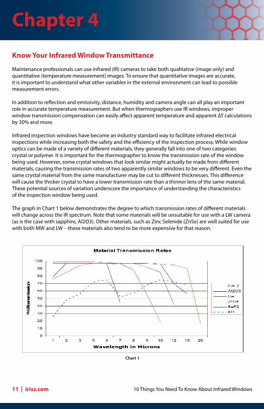
The graph in Chart 1 below demonstrates the degree to which transmission rates of different materials will change across the IR spectrum. Note that some materials will be unsuitable for use with a LW camera (as is the case with sapphire, Al2O3). Other materials, such as Zinc Selenide (ZnSe) are well suited for use with both MW and LW – these materials also tend to be more expensive for that reason.
Chart 1
Chapter 4
11 | iriss.com

Copyright ©2009 by IRISS, inc. All rights reserved
Given the transmission variability across different wavelengths, one needs to define the transmission rate at a specific wavelength. Our research shows that this “PdM” wavelength is at about 9μm in the LW band and about 4μm in the MW (SW) band.
For accurate temperature calculations, it is irrelevant whether the window’s transmissivity coefficient is 90%, or 50%... or something in between. What is important is that the thermographer knows the exact transmission rate. Then when the thermographer enters the correct coefficient into the camera or software, the final temperature calculation will be accurate and reliable. If, however, the thermographer is not aware of the actual transmission rate, or does not adjust for it, the errors can be significant.
Kirchhoff’s Law and Infrared WindowsAs discussed in Chapter 3, Kirchhoff’s Law shows us that the total infrared radiation a camera receives is actually composed of the total emitted, reflected and transmitted radiation from an object. With this in mind, the ideal window would therefore be one that allows 100% transmission, i.e. zero loss to emittance and reflection. To maximize transmittance, and minimize emittance and reflectance values, manufacturers carefully select optic materials and window coatings for their performance in specific or general wave bands. Unfortunately, as Chart 1 depicts, with the materials presently available, 99% is the highest transmission rate available (coated ZnSe in the LW portion of the spectrum).
The graph in Chart 2 shows how calculated temperatures can be adversely affected when a thermogra-pher improperly compensates for transmission. In this example, the transmission rate of the IR window is 0.50. The graph shows the apparent temperature when the imager settings are stepped down from 1.0 to 0.50. When transmission is properly compensated for, the actual temperature is shown to be 11.8° higher: very similar to the effects of emissivity compensation discussed in Chapter 3.
Chart 2
Chapter 4 CONT’D
iriss.com | 12
10 Things You Need To Know About Infrared Windows
All window optics will filter, or “attenuate” the amount of infrared radiation that ultimately reaches the imager. Our research shows that for calcium fluoride windows the attenuation reduces the temperature about 5% for every millimeter of window thickness (temperatures in the range of 60°-120°C). In addition, tilting the camera angle 30° to either side of 90° (perpendicular) reduces the temperature by an additional 2-3%.
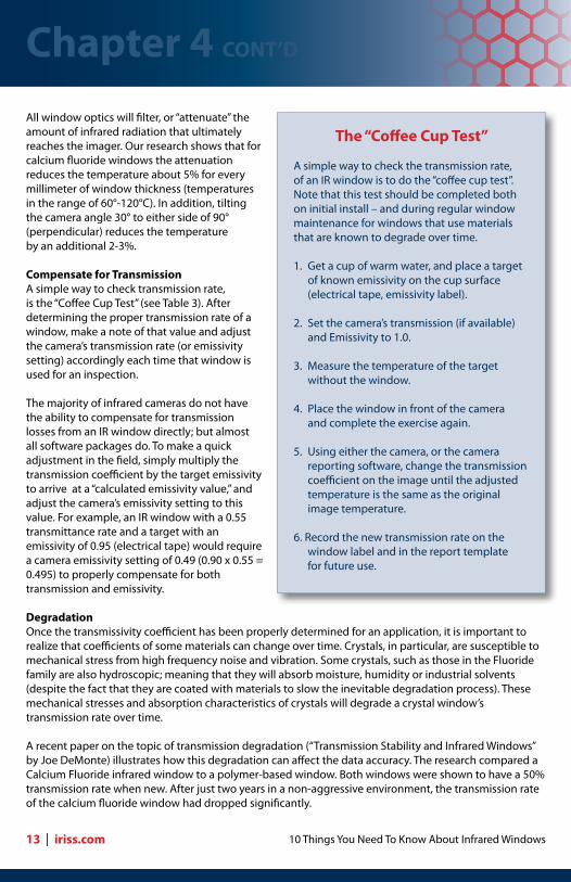
Compensate for TransmissionA simple way to check transmission rate, is the “Coffee Cup Test” (see Table 3). After determining the proper transmission rate of a window, make a note of that value and adjust the camera’s transmission rate (or emissivity setting) accordingly each time that window is used for an inspection.
The majority of infrared cameras do not have the ability to compensate for transmission losses from an IR window directly; but almost all software packages do. To make a quick adjustment in the field, simply multiply the transmission coefficient by the target emissivity to arrive at a “calculated emissivity value,” and adjust the camera’s emissivity setting to this value. For example, an IR window with a 0.55 transmittance rate and a target with an emissivity of 0.95 (electrical tape) would require a camera emissivity setting of 0.49 (0.90 x 0.55 = 0.495) to properly compensate for both transmission and emissivity.
DegradationOnce the transmissivity coefficient has been properly determined for an application, it is important to realize that coefficients of some materials can change over time. Crystals, in particular, are susceptible to mechanical stress from high frequency noise and vibration. Some crystals, such as those in the Fluoride family are also hydroscopic; meaning that they will absorb moisture, humidity or industrial solvents (despite the fact that they are coated with materials to slow the inevitable degradation process). These mechanical stresses and absorption characteristics of crystals will degrade a crystal window’s transmission rate over time.
A recent paper on the topic of transmission degradation (“Transmission Stability and Infrared Windows” by Joe DeMonte) illustrates how this degradation can affect the data accuracy. The research compared a Calcium Fluoride infrared window to a polymer-based window. Both windows were shown to have a 50% transmission rate when new. After just two years in a non-aggressive environment, the transmission rate of the calcium fluoride window had dropped significantly.
The “Coffee Cup Test”
A simple way to check the transmission rate, of an IR window is to do the “coffee cup test”. Note that this test should be completed both on initial install – and during regular window maintenance for windows that use materials that are known to degrade over time.
1. Get a cup of warm water, and place a target of known emissivity on the cup surface (electrical tape, emissivity label).
2. Set the camera’s transmission (if available) and Emissivity to 1.0.
3. Measure the temperature of the target without the window.
4. Place the window in front of the camera and complete the exercise again.
5. Using either the camera, or the camera reporting software, change the transmission coefficient on the image until the adjusted temperature is the same as the original image temperature.
6. Record the new transmission rate on the window label and in the report template for future use.
Chapter 4 CONT’D
13 | iriss.com

Copyright ©2009 by IRISS, inc. All rights reserved
For the test, an overhead clamp was heated to a stable temperature. The target was a bolt head that was covered with a piece of electrical tape with an emissivity value of 0.95. Figure 1 shows the target viewed without an infrared window. The temperature was shown to be 115.8°F. In preparation for viewing through the infrared windows, the transmission rate was adjusted to 50% in accordance with the rate defined two years prior (as discussed above). When the polymer window was placed in front of the camera (see Figure 2), the registered temperature was 115.9°F. When the target was viewed through a Calcium Fluoride crystal window the apparent temperature of the 115.8°F target registered just 82.4°F (as seen in Figure 3) due to the degradation in the crystal’s transmission rate. The result of this study clearly underscores the importance of compensating for the actual transmission rate of the IR window optic. In this case, the resulting measurement error is over 28%. (For additional information, this white paper which was published in the April 2009 edition of Uptime Magazine can be found at http://www.iriss.com/PDF/new_white_papers/Transmission_Stability_and_Infrared_Windows_030309.pdf
Recalibration of Window Transmittance The “Coffee Cup Test,” or some similar form of verification, should be performed prior to installation – and again prior to any important measurement or inspection if using an optic that is known to degrade over time. Furthermore, because each crystal is unique, transmittance must be tested for each crystal since each one will have a slightly different transmittance rate when new. (For additional information see UpTime Magazine; November 2007; “Opening the Windows;” Dougherty, Newberry & Schewe: http://www.uptimemagazine.com/digi/nov_07/index.htm.) Similarly each crystal’s rate of degradation will be unique as well.
However, if using an engineered polymer, testing a single window when it is new should be sufficient since all windows will be virtually identical in transmittance and since the material will not degrade over time.
Maintaining IR windows During maintenance shutdowns, firms should check gaskets and screws for seal integrity, and windows should be thoroughly cleaned with a compatible cleaning agent. If using crystal IR windows, this is also a great time check transmittance. Summary 1. Know the characteristics of the infrared window optic as it pertains to the wavelength of your camera (MW versus LW). 2. Test the IR window transmittance and document the result. 3. Compensate for the transmission attenuation for accurate temperature calculations. 4. Re-test each window’s transmission rate if the material is known to degrade over time (as with most crystal optics). 5. Include the windows in the general maintenance of the equipment to which it is attached.
Figure 1 Figure 2 Figure 3
Chapter 4 CONT’D
iriss.com | 14
10 Things You Need To Know About Infrared Windows
Summary1. Know the characteristics of the infrared window optic as it pertains to the wavelength of your camera (MW versus LW).2. Test the IR window transmittance and document the result.3. Compensate for the transmission attenuation for accurate temperature calculations.4. Re-test each window’s transmission rate if the material is known to degrade over time (as with most crystal optics).5. Include the windows in the general maintenance of the equipment to which it is attached.
Chapter 4 CONT’D
15 | iriss.com
Copyright ©2009 by IRISS, inc. All rights reserved
Field of View (FOV) Through an Infrared Window
The two questions most often asked by maintenance professionals getting ready to install infrared (IR) inspection windows on electrical equipment are: “How many windows will I require per panel” and “What diameter window is best?” The answer is “it all depends on Field of View (FOV).” It depends on the FOV of the camera, lens attachment (if used) and IR window.
Measurement Field of View (MFOV) First, let’s examine the camera and lens specifications. We are primarily concerned with the MFOV (Mea-surement Field of View), also referred to as the “Spot Size Ratio.”
Every camera defines its FOV across a horizontal/vertical axes. The Instantaneous Field of View (IFOV) is the smallest target the camera can ”see”. Although an IR camera can pick up numerous hot spots, many spots will be too small to measure accurately with a radiometric IR camera (one which displays temperature on the image). The MFOV, or Spot Size Ratio is the smallest target the imager can accurately measure.
The greater the resolution of the camera: the better the IFOV. For example, one top-selling camera uses a 640 x 480 pixel array. It has a MFOV of 500:1, while a 320 x 240 camera has an MFOV of 200:1. In these examples, a one-inch diameter target could be measured from a distance of 500 inches (41.7 feet) by the higher resolution camera; whereas the other camera would have a maximum distance of 200 inches (16.7 feet).
A telescopic lens (typically a 12° or 7° attached to a standard 24° lens) will also improve FOV by a factor of 2X and 3X respectively. Therefore, a 7° lens used on that high resolution camera would allow measure-ment of a one-inch target from a maximum distance of 125 feet (1”:500 x 3 = 1500” / 12”).
Think of resolution as the quality of your eyesight. When you go to the stadium to watch your favorite team, the poorer your eyesight, the closer you will need to be to the field to see your favorite player’s jersey number (temperature). Watching the game from high up in the “cheap seats,” good eyesight will help, but you may be too far away to see the detail of that jersey number. Good thing you brought those binoculars (the 7° telescopic lens attachment)!
Window Field of View (WFOV) Typically, IR cameras have a standard FOV of approximately 24°(horizontal) and 20° (vertical). So, it is advisable to do calculations based on a standard lens (since a wide angle may not always be available). Note that the calculation assumes that the FOV begins at the panel cover and extends a distance (d) from the panel cover to the targeted components. The length along that FOV is a distance (D). D is calculated by multiplying the distance (d) by the tangent of half the lens angle, then doubling the result.
Standard calculations assume that FOV starts at a single point, or vertex of the viewing angle. It does not take window size into account. So for a calculated D of 2.8” add an additional two/four inches when using a two or four inch window (yielding a D of approximately 4.8/6.8”).
Chapter 5
iriss.com | 16

10 Things You Need To Know About Infrared Windows
The illustration in Figure 1 shows the area inside a cabinet that can be viewed through an IR window using a camera with an 82° FOV lens. A typical switchgear compartment is 20 inches deep, therefore:
D = 2d x (tangent of 41°)
D = 2*20 x 0.87 = 34.8 inches
The calculations in Figure 1 indicate that with an 82° FOV lens, a thermographer can view 34.8 inches horizontally inside the panel. However, this calculation assumes the thermographer holds the camera fixed and perpendicular to the window plane. More likely, the thermographer will vary the viewing angle up to 30° from perpendicular in all directions. This effectively increases the FOV area by a factor of three.
Camera Angled for 2X standard FOV
D = (2*20) x 0.87 x 2
D = 69.6 inches
Camera Angled for 3X standard FOV
D = (2*20) x 0.87 x 3
D = 104.4 inches
Figure 1: Standard FOV calculation with fixed viewing angle
Visible Area Surface
Panel CoverIR Window
41°
d
D
Chapter 5 CONT’D
17 | iriss.com
D = Visible Area
d = cabinet depth or target distance
Figure 2: Standard FOV calculation (varying the viewing angle)
Copyright ©2009 by IRISS, inc. All rights reserved
Chapter 5 CONT’D
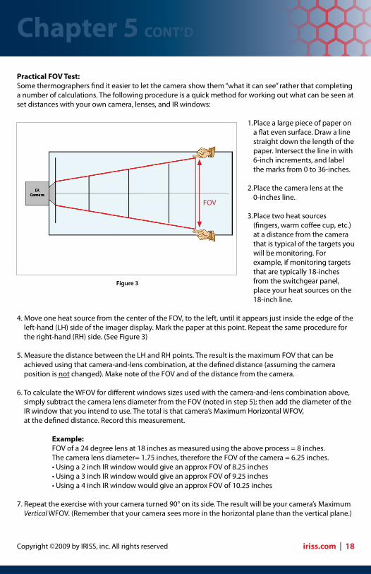
Practical FOV Test:Some thermographers find it easier to let the camera show them “what it can see” rather that completing a number of calculations. The following procedure is a quick method for working out what can be seen at set distances with your own camera, lenses, and IR windows:
1. Place a large piece of paper on a flat even surface. Draw a line straight down the length of the paper. Intersect the line in with 6-inch increments, and label the marks from 0 to 36-inches.
2. Place the camera lens at the 0-inches line.
3. Place two heat sources (fingers, warm coffee cup, etc.) at a distance from the camera that is typical of the targets you will be monitoring. For example, if monitoring targets that are typically 18-inches from the switchgear panel, place your heat sources on the 18-inch line.
4. Move one heat source from the center of the FOV, to the left, until it appears just inside the edge of the left-hand (LH) side of the imager display. Mark the paper at this point. Repeat the same procedure for the right-hand (RH) side. (See Figure 3)
5. Measure the distance between the LH and RH points. The result is the maximum FOV that can be achieved using that camera-and-lens combination, at the defined distance (assuming the camera position is not changed). Make note of the FOV and of the distance from the camera.
6. To calculate the WFOV for different windows sizes used with the camera-and-lens combination above, simply subtract the camera lens diameter from the FOV (noted in step 5); then add the diameter of the IR window that you intend to use. The total is that camera’s Maximum Horizontal WFOV, at the defined distance. Record this measurement.
Example:FOV of a 24 degree lens at 18 inches as measured using the above process = 8 inches.The camera lens diameter= 1.75 inches, therefore the FOV of the camera = 6.25 inches.•Usinga2inchIRwindowwouldgiveanapproxFOVof8.25inches•Usinga3inchIRwindowwouldgiveanapproxFOVof9.25inches•Usinga4inchIRwindowwouldgiveanapproxFOVof10.25inches
7. Repeat the exercise with your camera turned 90° on its side. The result will be your camera’s Maximum Vertical WFOV. (Remember that your camera sees more in the horizontal plane than the vertical plane.)
FOV
Figure 3
iriss.com | 18

10 Things You Need To Know About Infrared Windows
8. Record the results in a table like the one shown in Figure 4. (Note that these figures were taken using a FLIR P65 IR Camera.) This FOV matrix was calculated using the above technique and then multiplied by a factor of 3 to give the total WFOV through each type of IRISS IR Window, allowing for roughly a 30° angle of incidence. Keep your matrix with the camera for future reference.
Tip: Most thermographers will take FOV measurements at several distances that are relevant to the various applications they monitor. Also, try moving a target as close to your camera as possible until you can no longer bring the object into focus. This will show you the camera’s “minimum focus distance.” i.e. the closest you can get to a target and still be in focus. It is very useful to know your camera’s minimum focus distance,
since some cameras can be more than 24 inches, thereby limiting their use in electrical thermography.
Note: Although the above technique is not 100 % accurate it gives an extremely good result. Try it for yourself – it is a simple technique that really works!
Rule of ThumbBased on countless field tests for WFOV with a wide variety of cameras, most cameras have generated a horizontal WFOV of roughly two to three times (2X to 3X) the distance to the target; and a vertical WFOV of roughly 1.5X to 2X the distance to the target. This is based on cameras with a standard 24° or similar lens, using a maximum angle of incidence of 30°.
Therefore, based on this rule of thumb, a window located 20 inches (51 cm) from the intended targets would allow the thermographer to gather data from points that were separated by 40 to 60 inches (1m to 1.5m) side-to-side and separated by 30 to 40 inches (0.75 to 1m) top-to-bottom.
Note that it is impractical to use a multiplier in excess of 3X due to the difficulty matching the thermal image to locations within the panel. Obstructions in the panel may also make it impractical. As previously mentioned, viewing at too steep an angle can begin to affect other variables such as emissivity. Therefore, IRISS, inc. recommends a maximum of 3X as a “rule of thumb multiplier.
Summary1. Every camera has a Field-of-View (FOV) defined in degrees across a horizontal/vertical axis. Note that the FOV can vary depending on the type of lens used.2. Image Field of View (IFOV): The smallest detail that can be resolved.3. Measurement Field of View (MFOV): The smallest detail that can be accurately measured.4. Window Field of View (WFOV): The largest area that can be viewed through an infrared window allowing for a maximum angle of incidence of 30° off perpendicular.5. Rule of thumb for WFOV using a standard camera and lens is roughly 2 to 3 times the distance from the window to the target.6. Obstructions, such as phase dividers or cables, inside the cabinet may decrease actual field of view.
Chapter 5 CONT’D
19 | iriss.com
IR Target Distance VP50 FOV VP75 FOV VP100 FOV
8 inches Hor= 13.2 Ver= 9.9
Hor= 16.2 Ver= 12.9
Hor= 19.2 Ver= 15.9
12 inches Hor= 18.0 Ver= 13.5
Hor= 21.0 Ver= 16.5
Hor= 24.0 Ver= 19.5
18 inches Hor= 25.0 Ver= 18.75
Hor= 28.0 Ver= 21.75
Hor= 31.0 Ver= 21.75
24 inches Hor= 31.5 Ver= 24.0
Hor= 34.5 Ver= 27.0
Hor= 37.5 Ver= 30.0
Figure 4
Copyright ©2009 by IRISS, inc. All rights reserved
Proper Installation of Infrared Windows
Proper installation of the infrared window is critical for the long-term use of the window and for the long-term performance of the panel and equipment enclosure. Although an infrared window is not as strong as the steel it replaces, installing an IR window is no different than many other modifications that are commonly performed on switchgear and other electrical applications. Therefore, if a company has a policy for modifications such as: replacing or adding an ammeter or similar device, installing a visual inspection pane or modifying a cabinet to add a new conduit run, then it is logical to include infrared windows under the same policies. For example, one would want to refer to any existing policies relating to: pre-planning, design/installation approval, installation best practices and post-installation inspection by an in-house or external authority.
Do Not Pass “Go”Confirm the following prior to planning any modifications to an electrical equipment enclosure: •IngressProtection:EnsurethattheNEMAorIPratingoftheIRwindoworothercomponentisrated for at least the same level of protection that the current enclosure is rated for. Never install an infra red window or any other component with a lower rating than the equipment onto which it is being installed. •TestsandCertifications:EnsurethattheIRwindowshavebeentestedandapprovedbytherelevant certification bodies. Official test certificates and documentation should be easily obtained from the manufacturer. •ExplosionRatings(ifapplicable):Enclosureslocatedinintrinsicallysafeareasshouldnever be modified in the field unless designs have been cleared with, and post installation inspection and re-certification will be performed by an Authority Having Jurisdiction prior to start-up.
Identify All TargetsStart the process by identifying specific targets on each piece of equipment. In addition to fuses and breakers, most infrared surveys focus on bolted connections within the gear, as these areas are considered the weakest points. These areas include: •Cableconnections •Busbarconnections •Isolatororcircuitbreakerconnections
Make a quick inspection of the interior of the switchgear to identify these targets. Once identified, make every effort to standardize their emissivity while equipment is de-energized. Common methods include use of electrical tape, high-temperature paint or IRISS IR-ID labels. After emissivity standardization is complete, it is important to photograph each target since these photos will be used for report templates and future reference.
On many switchgear models, it is advisable to install viewing windows in the front and back for better access to the main breaker and bus connections. Ask the manufacturer for drawings and suggestions regarding the critical inspection locations for your equipment. This information, along with the experience and knowledge of the site maintenance engineer, will prove useful when calculating window placements and quantities.
Chapter 6
iriss.com | 20

10 Things You Need To Know About Infrared Windows
InstallationBefore picking up that drill, it is imperative to consider the following to ensure a successful, safe and useful installation: •Internalobstacles: Seek the permission from the local safety manager before removing internal Lexan TM (Perspex) covers. In some cases, you may not be able to remove the covers entirely. If this is the case, modify the covers by drilling or punching holes (without losing the IP2X requirement for some switchgear), or investigate custom guards that would allow for infrared transmission (such as the IRISS CAP Series.) • InternalCableRouting: Work from drawings on brand-new switchgear to confirm the internal cable routes. Make sure that contractors do not route these cables in front of the infrared windows. • DielectricClearances(distancefromenergized components): Where the IR window contains grills, or inspection orifices, it must comply with IP2X (13mm 0.5”). Safe dielectric clearances must be maintained for each window. IEEE C37.20.2, Table 1 specifies a minimum clearance distance for live components (versus maximum rated voltage).
PPE:Complete a detailed Risk Assessment (identifying all hazards that may be present during the installation) and a detailed Method Statement (detailing how the installation will be performed). Make sure that the installation crew has the correct levels of PPE to complete the task safely, especially if the installation involves energized work, in which case an energized Work Permit will also be required per NFPA 70E/CSA Z462. All work procedures, assessments and permits must be outlined in the Risk and Method statement.
Installation InstructionsEnsure that you comply with the Installation Instructions like those in Figure 1, provided by the window manufacturer. These will provide you with all the necessary information to ensure that the windows are installed correctly.
ToolsBefore starting any installation, double-check to be sure that all required tools are readily available. Traditionally, IR window installations take place during plant shutdowns therefore, you will need to ensure that you have all the cutters, drills, drill bits, metal treatments, etc. already kitted and at-hand (including spares). Remember, that you will probably not be able to run to a hardware store to purchase new punches at 2 in the morning! A complete list of required tools can be obtained from the IR window manufacturer.
Figure 1
Chapter 6 CONT’D
21 | iriss.com
MaximumVoltage (kV)
MinimumClearance
In cm
4.76 5.5 14
8.25 6.5 17
15.0 8.0 20
27.0 12.0 30
38.0 15.0 36
Table 1: from IEEE C37.20.2

Copyright ©2009 by IRISS, inc. All rights reserved
LabelingAffixing information labels is an important final step in the installation process. One label should identifywhat the window is and how to use it. A second sticker should contain the following information thatwill be critical in performing a thorough and accurate infrared inspection: • Eachinspectionwindowshouldbegivenauniquenumber.Thiswillbeinvaluable,especially,ifthere are multiple windows on one electrical panel. • Documentthetypeofwindow(MWorLW)andtheeffectivewavelengthofthewindow(asdetailed in Chapter 2). • Recordthetransmissionrateofthewindow,andthepropertransmissioncompensationvaluefor the MW and LW. • RecordalltargetdataontheontheIDlabel.Themostcommonmethodofdocumentingtarget location is the clock face method: i.e. bus bar connections at 4 o’clock. It should be noted that there may be multiple targets being surveyed through the IR window. • Somecamerasdonothavetheabilitytoadjusttheexternalopticstransmission;therefore, thermographers may use the emissivity settings on the camera to cover transmission and emissivity losses. Multiply the target emissivity by the transmission rate of the window (as detailed in Chapter 4).
BaselineAfter the window installation is completed, the thermographer should conduct a benchmark inspection to set the base line. Data for each inspection point should be recorded in a spreadsheet or database for trend analysis over several surveys. There are software programs available to assist with database management and trending of infrared data.
Figure 2
Chapter 6 CONT’D
iriss.com | 22

10 Things You Need To Know About Infrared Windows
Figure 3 Figure 4 Figure 5
What Can I See Through an Infrared Viewing Pane?An infrared window allows you to check the condition of electrical conductors and circuit parts. As with traditional thermographic inspections, the camera is very good at detecting and displaying even slight temperature differences very clearly. Therefore, when there is an electrical fault producing a temperature rise, the camera will display the image of the faulty components very clearly. However, if everything is at temperature equilibrium, it is difficult for the camera to display an image showing much of anything.
Figures 3, 4 and 5 are images taken through an IR window — no apparent faults are present.
Figures 6, 7 and 8 are images taken through an IR window — temperature rise due to load imbalance and poor connections are evident.
Figure 6 Figure 6 Figure 7
Chapter 6 CONT’D
23 | iriss.com

Copyright ©2009 by IRISS, inc. All rights reserved
Summary1. Do your homework first: check all applicable certifications and ratings.2. Gather as much information as possible, while the equipment is deenergized. a. Take high quality digital pictures b. Standardize the target emissivity c. Make detailed measurements d. Note any internal obstacles e. Conduct any outstanding maintenance tasks3. Complete a thorough Risk Analyses and Method Statement before starting energized installations.4. If possible, complete a specialized training program dealing specifically with installation of infrared windows.5. Remember to label the windows correctly, since this data will be used during future inspections.6. Do a complete infrared inspection at the end of the window installation in order to create a benchmark/baseline for future inspections.
Chapter 6 CONT’D
iriss.com | 24

10 Things You Need To Know About Infrared Windows
Certifications and Standards
“What standards and certifications are relevant to infrared (IR) windows?” This is one the most commonly asked questions when engineers and safety professions begin to investigate IR windows. Trying to sort through the myriad of UL, cUL, IEEE, CSA and other standards can be a daunting task. This chapter will attempt to clarify some of the most pertinent standards.
UL50VThe UL 50V classification for Infrared Viewports is the only standard that relates specifically to infrared windows. It serves more as a classification than an actual standard for performance-of-build characteris-tics. Specifically it states:
Infrared Viewports are a fixed aperture, consisting of one or more openings or a solid infrared transmitting media, surrounded by a mounting bezel or frame, that provide a means for the passage of infrared radiation.
The UL50V classification is actually a mix of two distinctly different product categories: the “infrared window” (also known as IR sightglasses or IR viewing panes) and the “infrared port.” While both will allow the thermographer to perform infrared inspections of targets located inside an enclosure or behind a barrier, they are mechanically very different. Specifically, IR windows provide a barrier to separate the thermographer from the environment surrounding the target. In contrast, an IR port is essentially a hole. When opened, it effectively removes the barrier between the thermographer and the target. This distinction becomes important when considering the Personal Protective Equipment (PPE) implications of NFPA 70E/CSA Z462 (see Chapter 8).
UL508UL508 covers industrial control equipment and control panels under 1500 volts. Equipment covered by these requirements is intended for use in an ambient temperature of 0-40°C (32-104°F) unless specifically indicated for use in other conditions.
UL 508AUL508A covers industrial control panels intended for general use, with an operating voltage of 600 or less. This equipment is intended for installation in ordinary locations, in accordance with the National Electrical Code (ANSI/NFPA 70), where the ambient temperature does not exceed 40°C (104°F).
UL 746CUL 746C sets the impact and flammability standards for polymeric materials used in electrical equipment up to 1500 volts. Any plastic or polymer forming part of an infrared window must pass flammability tests at room temperature, and must remain intact during an impact test performed at 0°C (32°F). It is worth noting that of the crystal optics capable of transmitting in the long wave portion of the infrared spectrum (8μm to 14μm), there are no fluoride-based crystals capable of passing the impact tests required in 746C. However, because they are classified as “glass” under the standard, they are not required to test for impact as long as they are thicker than 1.4 mm.
Chapter 7
25 | iriss.com
Copyright ©2009 by IRISS, inc. All rights reserved
IEEEC 37.20.2 Section a.3.6Viewing panes mounted in medium and high voltage equipment (600 volts to 38kv metal clad and 72kv station type gear) are required to withstand impact and load per IEEE C37.20.2 Section a.3.6. The standard specifically states that the viewing pane must withstand the impact and load from both sides (inside/outside) and the viewing pane must not “crack, shatter or dislodge.”
Unlike with UL, there is no exemption given to crystals or glass under the IEEE standard, and the only crystal capable of passing the test in this standard is sapphire (which is non-transmissive in the 8μm to 14μm (LW) portion of the spectrum where PdM cameras typically function).
Lloyd’s Register Type ApprovalLloyd’s Register provides independent, third-party approval certificates attesting to a product’s conformity with specific standards or specifications. It also verifies the manufacturer’s production quality systems through a combination of design reviews and type testing. There is growing international awareness of the importance of third-party certifications such as those offered by Lloyd’s.
Ingress Protection/Environmental RatingIP65 is an international standard (defined in IEC 60529) that classifies products as “dust tight,” with complete protection against contact (with parts contained within the enclosure). It also covers resistance to directed water jets. IP testing must be performed and certified by third-party testing labs, such as SIRA.
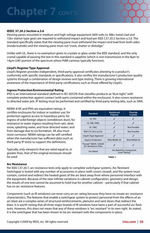
NEMA 4/4X and IP65 are equivalent ratings. It certifies enclosures for indoor or outdoor use; for protection against access to hazardous parts; for ingress of solid foreign objects (windblown dust); for resistance to water ingress resulting from rain, sleet, snow, splashing water, and hose directed water; and from damage due to ice formation. 4X also must resist corrosion. NEMA ratings can be self-certified when the manufacturer has sufficient data (such as third-party IP tests) to support the definitions.
Typically, only viewports that are rated equal to, or greater than, that of the original enclosure should be used.
Arc ResistancePer IEEE C37.20.7, arc resistance tests only apply to complete switchgear systems. Arc Resistant Switchgear is tested with any number of accessories in place (with covers closed), and the system must contain, control and redirect the heated gases of the arc blast away from where personnel interface with the equipment. Because of the near-infinite variations in cabinet configuration, geometry and design, the results of one test cannot be assumed to hold true for another cabinet – particularly if that cabinet has no arc resistance features.
Components (such as IR windows) can never carry an arc rating because they have no innate arc resistance characteristics. The features that enable a switchgear system to protect personnel from the effects of an arc blast are a complex series of structural reinforcements, plenums and vent doors that redirect the blast. It is worth noting that all three major brands of IR windows have been a part of successful arc flash tests. However, this does not mean that any of these windows is “arc resistant” in its own right. As stated, it is the switchgear that has been shown to be arc resistant with the components in place.
Chapter 7 CONT’D
iriss.com | 26
Standard ReinforcedPolymer
FluorideCrystals
UL 50V ✓ ✓
UL 508, 508A ✓ ✓
UL 746C ✓ Not Possible
IEEE C37.20.2 (a.3.6) ✓ Not Possible
Lloyd’s Type Approval ✓ ✓
Ingress Protection IP65/NEMA 4X IP65/NEMA 4X
“Passed” 50kVA / 63kVAArc Resistance Tests ✓ ✓
Arc Rated Arc Rated No Component Level “Rating”
Table 1

10 Things You Need To Know About Infrared Windows
Additional ResourcesFor a more information on the standards in this chapter, please refer to the following white papers and web sites:
• Foradditionalinformationaboutstandardsandhowtheyrelatetoinfraredwindowdesign,see “Safer by Design,” at http://www.iriss.com/PDF/new_white_papers/IRISS_Safer_by_Design_p.pdf • Foradditionalinformationaboutarcresistancestandards,see“TheMythofArcResistantWindows,”at http://www.iriss.com/PDF/new_white_papers/IRISS_IR_Win_Arc_Ratings_Dec08_p.pdf • ForadditionalinformationaboutUL50V,see: http://ulstandardsinfonet.ul.com/tocs/tocs.asp?doc=o&fn=o0050v.toc • ForadditionalinformationaboutUL508,see: http://ulstandardsinfonet.ul.com/scopes/scopes.asp?fn=0508.html • ForadditionalinformationaboutUL508A,see:http://ulstandardsinfonet.ul.com/scopes/0508a.html • ForadditionalinformationaboutUL746C,see: http://ulstandardsinfonet.ul.com/scopes/scopesnew.asp?fn=0746C.html • ForadditionalinformationaboutIEEEC37.20.2sectiona.3.6,see: http://standards.ieee.org/reading/ieee/interp/C37.20Series.html • ForadditionalinformationaboutLloyd’sTypeApproval,see: http://www.lr.org/Industries/Marine/Services/Certification/Type+approval.htm • ForadditionalinformationaboutIngressProtection,see: http://www.engineeringtoolbox.com/ip-ingress-protection-d_452.html • ForadditionalinformationaboutNEMAratingssee:http://www.nema.org/prod/be/enclosures/ • FormoreinformationonIEEEC37.20.7,see: http://standards.ieee.org/reading/ieee/std_public/new_desc/switchgear/C37.20.7-2001.html
Chapter 7 CONT’D
27 | iriss.com
Infrared Windows and Arc Ratings – Dispelling the myth of
“Arc-Resistant IR Windows”
by: Martin Robinson & Tim Rohrer, IRISS, inc.
Abstract
IR Windows and PPE – Relevant Outtakes from NFPA 70E, 2009
by: Martin Robinson & Tim Rohrer, IRISS, inc.
NFPA and its Implications on Thermographic Inspections
by: Martin Robinson & Tim Rohrer, IRISS, inc.
Safer By DesignThe History of IRISS Infrared Inspection Windows
Martin Robinson, Level III Thermographer
ROI Case Study 1 – Paper Mill Saves Budget Dollars
with IR Window Program
by: Martin Robinson
Overview
Transmission Stability & IR Windows Page 1© 2009; Joe DeMonte
Transmission Stability and Infrared Windows:
The Effects of Transmissivity on Data Accuracy
by: Joe DeMonte
ASNT/PdM Level III Thermographer
Abstract
As the saying goes, “garbage in, garbage out.” This truism is every bit as applicable in
thermography as it is in computer data-mining. The difference is that the inaccurate data which
leads a thermographer to a false-negative conclusion could result in a multi-million dollar
catastrophic failure of a company’s electrical distribution system. In fact, the implications to
personnel safety, plant assets and production downtime make the results of transmissivity errors
more like toxic waste than mere “garbage.”
When using infrared (IR) windows or sightglasses, it is imperative to understand the accurate
transmission rate of the optic used in the infrared window. As this paper will explore, failure to
accurately compensate for actual transmission attenuation can lead to significant errors in data.
The magnitude of the error is based on the exponential effect that target surface temperature
has on radiated infrared energy. In short, temperature differences (T) will appear to be
minimized if the effects of transmission attenuation are not considered, or if not accurately
compensated for. Such errors in T may thereby lead thermographers to underestimate the
magnitude of many serious electrical faults.
IR Window Transmittance Temperature Dependence Robert P. Madding, Infrared Training Center, FLIR Systems, Inc.
ABSTRACT
While fluoride-type IR windows are inexpensive and have good transmittance in the mid-wave IR band (3 to 5 micrometers), their transmittance drops rapidly in the long wave IR band (8 to 12 micrometers). We can characterize the graybody approximation of such a window by measuring its IR bandpass transmittance with our IR camera. But as the IR window clearly is not “gray” but a spectral transmitter, the transmittance measured for one target temperature at one window temperature can be different for other target and window temperatures. Does this pose a serious problem for the condition-monitoring thermographer? This paper addresses the issue by modeling the effect of the non-grayness of fluoride-type IR windows in the nominal 8 to 12 micrometer waveband and gives quantitative results. We will show the magnitude of this effect and how to deal with it. If you use low-cost IR windows, you need to know the results of this study. Keywords: IR window, emissivity, IR window transmittance, condition monitoring INTRODUCTION
IR windows are being used more and more to enhance safety and increase the IR accessibility to important targets for condition monitoring. We used to remove the cabinet covers from the rear of 4160 volt switchgear to view the connections with our IR cameras. This was a cumbersome, time-consuming, and somewhat dangerous job to remove up to 8 bolts and lift a heavy steel cover away from live equipment. One false move, and an arc flash was the result. Another area we were unable to observe was motor connection boxes. These are but two examples of numerous cases where, with IR windows, we can now look into these areas much more safely and conveniently. Figure 1 gives an example of viewing motor connections through an IR window. This window has a transmittance of about 50%. Target emissivity is about 0.95. If your IR camera doesn’t have IR window transmittance compensation, the best approximation is to find the product of the IR window transmittance times the target emissivity. This is quite accurate, provided the target reflected apparent temperature, IR window temperature, and IR window reflected apparent temperature are all equal.

Copyright ©2009 by IRISS, inc. All rights reserved
Summary1. The only standard that applies specifically to infrared windows is the UL50V – it is actually more of a classification than a standard.2. All other standards that are cited may have a bearing on some aspect, or use, of a window.3. UL508 and 508A are classifications for components used on electrical panels.4. UL746C is a standard requiring flammability and impact tests for polymeric materials used on electrical equipment. Long wave compatible crystals are unable to pass the impact tests required of this standard.5. IEEE C37.20.2 Section a.3.6 is the impact and load requirement for all viewing panes installed on medium and high-voltage switchgear. Panes made from crystals or glass will not pass these requirements – that is why all visual inspection panes installed on new switchgear are made of Lexan™ or Plexiglas™. Unfortunately, those materials are not IR transmissive. Of long wave compatible IR windows, only a reinforced polymer optic meets the requirements of this standard.6. Lloyd’s Type Approval is a third-party verification of standards, and a verification of quality and design.7. Ingress protection standards certify that an enclosure is capable of sealing out various levels of environmental contaminants. IP65 and NEMA 4 are equivalent standards indicating protection against dust and water ingression.8. Arc resistance is a standard that applies only to switchgear – not to components. All three major window manufacturers have passed arc tests with their windows as part of switchgear assemblies. However the Arc Rating applies to the complete switchgear – not individual components
Chapter 7 CONT’D
iriss.com | 28
10 Things You Need To Know About Infrared Windows
Arc Flash, NFPA and OSHA: Implications on Infrared Inspections
An arc flash incident is reported every 18 minutes in the US. From these, roughly 20 people per day sustain arc-induced burns, and 5 to 10 workers suffer incurable third-degree burns over more than half their body. Sadly, on average, more than one worker a day never goes home – the victim of an arc flash fatality.
What is an Arc Flash and What are the Risks?An arc flash is a short circuit through the air that creates an explosion equal in force to one to three sticks of dynamite. Since most incidents are triggered by some type of human interaction, the same dynamite-like blast occurs within a few feet of the worker.
Common triggers are 1) dropping tools or panels, 2) making accidental contact with energized parts, or 3) changing the state of the equipment. An arc usually starts as a phase-to-ground short circuit. This “bolted fault” is one bridged by an object (a wrench for example) with limited current carrying potential. However, when the initial arc vaporizes the copper conductor, it produces a small, hyper-conductive cloud of copper plasma and ionized gases. This conductive cloud then forms a bridge changing the short to phase-to-phase. It is this “unbolted fault” that grows in intensity, producing a blinding flash along with ultra-high temperatures. The explosion feeds on itself, and the heat converts all materials in the vicinity to plasma. The copper conductor expands 67,000 times its initial size in a fraction of a second. It is this rapid expansion that creates the pressure wave that rips apart switchgear and sends molten shrapnel toward anything in its path.
How do Electrical Hazards Compare to Other EHS Hazards?Today, many plant safety concerns are well publicized and understood due to aggressive campaigns from Environmental Health and Safety (EHS) Departments. However, electrical safety has largely been left to the Electrical Department, since it is a highly specialized topic.
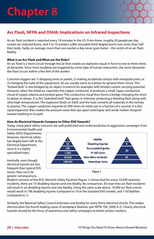
Ironically, even though electrical injuries are less frequent than typical EHS issues, they carry far greater consequences. Modern versions of the W.H. Heinrich Safety Pyramid (Figure 1) shows that for every 10,000 nearmiss incidents, there are 10 disabling injuries and one fatality. By comparison, 85 near-miss arc flash incidents will result in six disabling injuries and one fatality. Using the same scale above, 10,000 arc flash events would result in 706 disabling injuries (compared to 10 in the standard EHS model), and 118 fatalities (compared to 1).
Similarly, the National Safety Council estimates one fatality for every thirty electrical shocks. This makes electrocution the fourth leading cause of workplace fatalities (per NFPA 70E; 2009; K.2). Clearly, electrical hazards should be the focus of awareness and safety campaigns to better protect workers.
Figure 1
Chapter 8
29 | iriss.com

Copyright ©2009 by IRISS, inc. All rights reserved
NFPA 70BThe National Fire Protection Association (NFPA) developed the NFPA 70B standard for Electrical Equipment Maintenance. The standards set forth have been instrumental in saving lives, safeguarding plant assets and cutting downtime. Among its recommendations, NFPA 70B states that thermography should play a key role in monitoring faults in energized electrical equipment. The NFPA 70B standard also calls for monitoring transformers, switchgear and the power distribution equipment at least annually – in some cases, quarterly. These inspections should occur with the conductors and connections exposed and under full-load. Unfortunately, opening electrical equipment is not only time consuming, it is also dangerous.
NFPA 70E, OSHA 1910 and CSA Z462In 1976, NFPA formed a committee to create the NFPA 70E standard. The goal was to address electrical safety in the workplace and to provide OSHA with a document it could reference when issuing citations and fines (the NEC and 70B did not lend themselves to this). Since its first edition in 1979, NFPA 70E has
become the world’s most-referenced electrical safety document.
In 2009, Canada enacted CSA Z462 – an electrical safety standard that is harmonized with NFPA 70E. In fact, every industrialized country has implemented some type of electrical safety standard; many of which are harmonized with NFPA 70E, or are influenced by the NFPA 70E standard.
The thrust of NFPA 70E/CSA Z462 and the clear message from OSHA 1910 is that personnel should not be exposed to energized conductors and circuit parts. In other words: keep the panels and doors closed when the equipment is energized. Exceptions can be made in specific circumstances where energized work is required (such as diagnostic activities). In those cases, the standard requires personnel to utilize Personal Protective Equipment (PPE).
The most recent edition considers thermographic inspections performed on 1kV to 38kV Metal Clad Switchgear outside the restricted approach boundary as a three (on a scale of 4) Hazard/Risk Category (HRC). This means that scanning an open panel is on a par
with opening a hinged cover on the same panel. This task requires extensive PPE – including a minimum of a 25cal/cm2 flash suit (Figure 2).
NFPA 70E is well known for its Hazard/Risk (HRC) Table for PPE selection. It states very clearly in 130.7(A) that PPE is “intended to protect a person from arc flash and shock hazards.” It goes on to say that plant personnel could still sustain curable burns, even while using the correct PPE. Further, it explains that PPE does not protect from explosive effects of an arc blast.
In 130.9, the standard explains that the calculations in the HRC tables make certain assumptions with regard to clearing time and the available fault current. For this reason, it is suggested that companies conduct an Arc Flash Analysis (AFA). Yet even with an AFA, companies must be vigilant. A study by a multi-national services provider found that over 20% of breakers were not at 100% (slow trips), while more than 10% didn’t trip at all. One reason: most companies are not following manufacturer recommendations to exercise the breakers at fixed intervals. Because available current and duration determine the incident energy, even the slightest delay in closing can create an explosion well beyond the capacity of any PPE.
Figure 2
Chapter 8 CONT’D
iriss.com | 30

10 Things You Need To Know About Infrared Windows
When Should Personnel Utilize PPE?NFPA 70E/CSA Z462 directs personnel to utilize elevated levels of PPE when they are exposed to energized electrical conductors or circuit parts. Even if the panels are closed, PPE should be worn if there is the potential for an electrical hazard, such as a change-of-state.
Use of an IR window maintains an IP65/NEMA 4X seal on the enclosure panel. Therefore, even when open, the window maintains what NFPA terms an “enclosed” and “guarded” condition. Additionally, scanning through an IR window is a noninvasive task that does not create a risk of electrical hazard (no change-of-state). As long as the thermographer is confident that the equipment has been properly installed and maintained, and the equipment is not in danger of changing state. Then, the HRC for using an IR window would be the same level as “reading a panel meter while operating a meter switch,” which NFPA rates as HRC 0.
Additional Resources:For a more information on the standards in this chapter, please refer to the following white papers and web sites: • ForadditionalinformationabouthowNFPA70E,NFPA70BandOSHAeffectelectrical thermography, see the “Standards Implications on Electrical Thermography” white paper at: http://www.iriss.com/PDF/new_white_papers/IRISS_NFPA_W_P_Dec08_p.pdf • ForadditionalinformationaboutNFPA70B,see: http://www.nfpa.org/aboutthecodes/AboutTheCodes.asp?DocNum=70B • ForadditionalinformationaboutNFPA70E,see: http://www.nfpa.org/aboutthecodes/AboutTheCodes.asp?DocNum=70E • ForadditionalinformationaboutOSHA1910,see: http://www.osha.gov/SLTC/electrical/standards.html • ForadditionalinformationaboutCSAZ462,see: http://www.csa.ca/products/occupational/Z462/Default.asp?language=English
Figure 3
Summary1. Working with energized electrical components is among the most dangerous activities found | in the workplace. 2. Preventive maintenance standards such as NFPA 70B require infrared surveys of fully loaded and energized conductors and circuit parts at least annually. 3. OSHA 1910, NFPA 70E and CSA Z462 all require that personnel are not exposed to energized conductors and circuit parts unless absolutely necessary. 4. If personnel must access energized equipment, they are required to utilize PPE suited for the level of the hazard/risk of the task they are performing. 5. Infrared windows allow inspections to take place with the cabinet panels closed; thereby not exposing personnel to energized components and elevated hazard/risks. Therefore, the HRC level required when performing an IR inspection through a sealed window would be HRC 0 – the same as taking a meter reading or performing other administrative functions around enclosed
Chapter 8 CONT’D
31 | iriss.com

Copyright ©2009 by IRISS, inc. All rights reserved
Infrared Window Program Benefits
Companies implement an infrared (IR) window program for a variety of reasons, but most tend to fall into a few categories: •Standardscompliance •Safety •Riskmanagement •Costsavings/efficiency •Datamanagement
Standards ComplianceAfter performing arc flash studies, many companies are surprised to find a number of applications with incident energy calculations that exceed available PPE levels. Other applications may be too close to walls to allow workers to perform scans outside the Restricted Approach Boundary. Since these applications are deemed “un-inspectable”, IR windows are the only solution. Closed-panel inspection using IR windows complies with OSHA, NFPA and CSA mandates, all without requiring elevated levels of PPE.
Contrary to popular belief, voltage is not necessarily the best predictor of arc flash energy. In fact, the three biggest influences on the incident energy are: the available current, the fault clearance time, and personnel distance from the arc. It is very common to find that some 480V applications have incident energy calculations well in excess of available PPE protection levels. Lower voltage applications may carry higher current loads, and may experience longer delays before tripping.
The warning label in Figure 1 was found on a piece of 480V switchgear. Look closely and you will see that the Flash Hazard Boundary is over 31 feet, and it warns “Extremely Dangerous, No PPE Class Found” because the 108.8 Cal/cm2 exceeds the 40Cal/cm2 PPE that they had on site.
Safety NFPA 70E (Article 100; Arc Flash Hazard; FPN No.1) states: “Under normal operating conditions, enclosed energized equipment that has been properly installed and maintained is not likely to pose an arc flash hazard.” Conversely, just removing a panel cover on a 600V MCC or 1000V+ switchgear, is rated by NFPA/CSA as an HRC level four (on a scale of 1 to 4).
The message is clear: it is safer to keep electrical equipment closed whenever possible. Non-invasive work processes, such as using an IR window, should be encouraged as a way to increase the safety of personnel. In fact, use of IR windows has been estimated to reduce the risk of triggering an arc flash during an inspection to less than 0.1%.
Chapter 9
iriss.com | 32
Figure 1
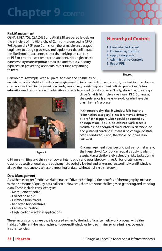
10 Things You Need To Know About Infrared Windows
Risk ManagementOSHA, NFPA 70E, CSA Z462 and ANSI Z10 are based largely on the principle of the Hierarchy of Control - referenced in NFPA 70E Appendix F (Figure 2). In short, the principle encourages engineers to design processes and equipment that eliminate the likelihood of accidents, rather than relying on controls or PPE to protect a worker after an accident. No single control is necessarily more important than the others, but a priority is placed on preventing accidents, rather than responding to them.
Consider this example: we’d all prefer to avoid the possibility of an auto accident. Antilock brakes are engineered to improve braking and control, minimizing the chance of an accident. Yet, in the event of a crash, we can rely on air bags and seat belts to protect us. Driver education and testing are administrative controls intended to train drivers. Finally, since in auto racing a
driver’s risk is high, they even wear PPE. But again, the preference is always to avoid or eliminate the crash in the first place.
In thermography, the IR window falls into the “elimination category”, since it removes virtually all arc flash triggers which could be caused by an inspection. The closed-cabinet work process maintains the energized conductors in an “enclosed and guarded condition”; there is no change-of-state of the conductors; and, therefore, no increase in risk level.
Risk management goes beyond just personnel safety; the Hierarchy of Control can equally apply to plant assets. Plants deliberately schedule risky tasks during
off-hours – mitigating the risk of power interruption and possible downtime. Unfortunately, most diagnostic testing requires the equipment to be fully loaded and energized. Accordingly, an IR window allows thermographers to record meaningful data, without risking a shutdown.
Data ManagementAs with most other Predictive Maintenance (PdM) technologies, the benefits of thermography increase with the amount of quality data collected. However, there are some challenges to gathering and trending data. These include consistency in: •Measurementpoint •Collectionangle •Distancefromtarget •Reflectedtemperatures •Cameracalibration •Highloadonelectricalapplications
These inconsistencies are usually caused either by the lack of a systematic work process, or by the habits of different thermographers. However, IR windows help to minimize, or eliminate, potential inconsistencies.
Hierarchy of Control:
1. Eliminate the Hazard2. Engineering Controls3. Apply Safeguards4. Administrative Controls5. Use of PPE
Figure 2
Figure 3
Chapter 9 CONT’D
33 | iriss.com

Copyright ©2009 by IRISS, inc. All rights reserved
Windows ensure that measurements are taken at the same angle, from the same point, and from the same distance each time. Furthermore, thermographers should pick the exact target areas, and mark them with tape or high-emissivity labels. Information on each target should be noted on a label next to the window (discussed fully in Chapters 3 and 6).
This systematized and consistent approach leads to more accurate and “trendable” data. The systematic approach to data collection can also improve a firm’s succession planning, or allow for greater flexibility in the event a company wishes to bring the thermography program in-house.
Cost Savings/EfficiencyThe time required to remove bolted panels, image the interior of the cabinet and reapply the panel covers is roughly a one-hour job for two men. Imaging through an infrared window takes one man five to six minutes. The efficiencies that a Reliability Department realizes from using IR windows are so significant that they typically pay for themselves by the first or second inspection cycle (see Chapter 10).
SummaryThere are several advantages to using infrared windows:1. Standards compliance: the equipment maintained in an enclosed and guarded condition without creating a potential electrical hazard during inspection. Therefore elevated levels of PPE are not required when using an IR window.2. Safety: the non-intrusive inspection does not elevate the risk of electrocution or of triggering an arc flash incident.3. Risk management: the Hierarchy of Control requires engineers and managers to eliminate risk where possible (as opposed to relying on engineering controls or PPE to protect personnel after the accident happens). Use of IR inspection windows eliminates the high-risk behaviors involved with open-panel inspection and replaces them with a non-intrusive work process.4. Data management: IR windows provide a systematic approach to data collection during inspections – same target, same location, same angle, and same distance. Consistency in the data collection process leads to more trendable data in any PdM process.5. Cost savings/efficiency: using infrared windows has been shown in time studies to eliminate over 90% of the time involved with inspections. And after all… time is money.
Chapter 9 CONT’D
iriss.com | 34

10 Things You Need To Know About Infrared Windows
Infrared Window Cost Benefit Analysis
Studies show that traditional open-panel infrared (IR) inspections are both time consuming and a poor use of high-value resources (electricians and thermographers). Bolted panels are designed to make access to energized conductors difficult. Furthermore, use of bulky personal protection equipment (PPE) makes the process even more difficult.
Time-motion studies indicate that a team of two electricians will take about 30 minutes to safely remove a bolted panel. After an average six minutes to scan the interior, the electricians then require the same 30 minutes to replace the panel. With a typical three-man inspection team, this translates into 3.3 manhours per panel. (Assuming the facility provides two in-house electricians to open panels for a contract thermographer, the man-hours drop to 2.2, but this doesn’t account for the thermographer’s daily rate). In addition to panel removal and inspection, PPE suit-up and removal further increases the time. On average, it takes thirty minutes to fully suit-up and dress-down with Category 3 or 4 PPE. For a threeman team, this adds another 1.5 man-hours every time the team starts a shift, or takes a break. Depending on the work environment, this could mean thousands of dollars spent on “wardrobe changes”.
As companies dig deeper into the numbers, it becomes increasingly evident that open-panel inspections are costing them significant amounts of money. For example, the thermographer (whether in-house or contract) is spending roughly 60 minutes out of 66 waiting for the electricians to open/close panels. That’s over 5.5 idle hours in a six-hour workday. Meanwhile, the two electricians will spend a combined 12 minutes of each 66 waiting for the thermographer to finish his scan. Infrared windows allow thermographers to conduct surveys, while eliminating these non-productive wait times.
The use of IR windows makes PdM personnel vastly more efficient. The PPE requirement is reduced to the level of “performing administrative tasks” around the electrical equipment. (Each facility will vary in its requirements – so please follow the recommendations from your site.) PPE suit-up and removal time is virtually eliminated. The thermographer requires no supporting cast and the scanning time averages just five to six minutes per window. Since more than 90% of the man-hours are eliminated, a complete Return on Investment (ROI) is realized within one or two inspection cycles.
Chapter 10
35 | iriss.com
Operation Man-Hours Total Man-Hours Rate ($/hr) Total
Cover Removal 0.5 1.0 $125.00 $125.00
Infrared Inspection 0.1 0.1 $150.00 $15.00
Cover Replacement 0.5 1.0 $125.00 $125.00
Thermographer Waiting Time 1.0 1.0 $150.00 $150.00
Electrician Waiting Time 0.1 0.2 $125.00 $25.00
Manpower Costs Per Inspection of One Energized Panel $ 435.00
Table 1

Copyright ©2009 by IRISS, inc. All rights reserved
Case StudyA US paper mill used a two-man IR survey team since the thermographer was qualified to assist the electrician. The study conducted prior to window installation revealed that the team spent 331 manhours to complete inspections on 65 separate applications (mostly switchgear and transformers). After installing 197 IR windows, the thermographer was able to survey all 65 applications, plus another five that were previously un-inspectable due to high incident energy levels, in just 16 man-hours. The total investment in windows was $42,050. The installation was out-sourced at a cost of $18,910. This one-time investment of $60,960 paid for itself after just two inspection cycles. The total ROI after five cycles was $135,915.
Infrared windows are just another case where good safety makes good business sense. The risk of catastrophic damage and downtime is reduced; along with the risk to personnel. Finally, IR windows allow personnel to work more efficiently. In short, IR windows allow companies to save time, save money, and stay safe.
Additional ResourcesFor a more information on the time studies quoted in this chapter, please refer to the following white paper: “ROI Case Study 1 – Paper Mill Saves Budget Dollars with IR Window Program,” at http://www.iriss.com/PDF/new_white_papers/ROI_IR_Windows_In_Paper_Mill_w.pdf
Summary1. Time-studies indicate that traditional open-panel inspections are very time-consuming. The man-hour costs can easily run to over $600 per panel.2. PPE suit-up and dress-down time is another costly task associated with traditional inspections. Costs can quickly exceed thousands of dollars per inspection cycle.3. Use of windows eliminates virtually all wait and PPE time. This translates into savings in excess of 90% of the time typically required to perform traditional thermographic inspections.4. Because of the man-hour savings which IR windows provide, most window programs see a return on investment within the first or second inspection cycle.
Chapter 10 CONT’D
iriss.com | 36

Call IRISS+1(941)-907-9128 US 877-704-7477
www.iriss.com