10-sdms-03 rev. 0 specification for optical · pdf filethis material standard specification...
TRANSCRIPT

Saudi Electricity Company الشركة السعودية للكھرباء
SEC Distribution Materials Specification 10-SDMS-03 Rev. 0
DATE: 28-09-2016G
10-SDMS-03
REV. 0
SPECIFICATION
FOR
OPTICAL FIBER GROUND WIRE (OPGW)
This specification is property of SEC and subject to
change or modification without any notice.

Saudi Electricity Company الشركة السعودية للكھرباء
SEC Distribution Materials Specification 10-SDMS-03 Rev. 0
DATE: 28-09-2016 G
Page 2 of 31
TABLE OF CONTENTS
1.0 SCOPE 2.0 CROSS REFERENCES 3.0 APPLICABLE CODES AND STANDARDS
4.0 DESIGN AND CONSTRUCTION REQUIREMENTS 4.1 General 4.2 Design Criteria 4.3 Stranded Metallic Wires 4.4 Central Fiber Optical Unit 4.5 Dispersion Un-shifted Single Mode Optical Fiber 4.6 Non-Zero Dispersion-Shifted Single Mode Optical Fiber 4.7 Color Coding 4.8 Composite OPGW 4.9 Reel Design 4.10 Markings
5.0 TESTS 5.1 Composite OPGW Tests 5.2 Fiber Tests
6.0 PACKING REQUIREMENTS
7.0 DATA SCHEDULE
Saudi Electricity Company الشركة السعودية للكھرباء
SEC Distribution Materials Specification 10-SDMS-03 Rev. 0
DATE: 28-09-2016 G
Page 3 of 31
1.0 SCOPE
This SEC Distribution Material Specification (SDMS) specifies the minimum technical
requirements for design, engineering, manufacture, inspection, testing and performance of composite overhead optical fiber-ground wire (OPGW), intended to be used in the Distribution System of Saudi Electricity Company, Saudi Arabia.
2.0 CROSS REFERENCES
This Material Standard Specification shall always be read in conjunction with latest SEC General Specification No. 01-SDMS-01, titled "General Requirements for All Equipment/Materials", which shall be considered as an integral part of this SDMS.
This SDMS shall also be read in conjunction with SEC Purchase Order or Contract
Schedules for project, as applicable.
3.0 APPLICABLE CODES AND STANDARDS The latest revision/amendments of the following codes and standards shall be applicable
for the equipment/material covered in this SDMS. In case of conflict, the vendor/manufacturer may propose equipment/material conforming to one group of Industry Codes and Standards quoted hereunder without jeopardizing the requirements of this SDMS.
3.1 IEC 60794-1-1 Optical Fiber Cables-Part 1-1 : Generic Specification -
General
3.2 IEC 60889 Hard-Drawn Aluminum Wire for Overhead Line Conductors
3.3 IEC 61089 Round Wire Concentric Lay Overhead Electrical Stranded
Conductors
3.4 IEC 61232 Aluminum Clad-Steel Wire for Electrical Purposes
3.5 ASTM B230M Standard Specification for Aluminum 1350-H19 Wire for Electrical Purposes
3.6 ASTM B398M Standard Specification for Aluminum-Alloy 6201-T81 Wire
for Electrical Purposes
3.7 ASTM B415 Standard Specification for Hard-Drawn Aluminum-Clad Steel Wires

Saudi Electricity Company الشركة السعودية للكھرباء
SEC Distribution Materials Specification 10-SDMS-03 Rev. 0
DATE: 28-09-2016 G
Page 4 of 31
3.8 ASTM B416 Standard Specification for Concentric-Lay-Stranded Aluminum-Clad Steel Conductors
3.9 EIA/TIA-455 Standard Test Procedures for Fiber Optic Fibers, Cables, Transducers, Sensors, Connecting and Terminating Devices and other Fiber Optic Components
3.10 EIA 492A Generic Specification for Optical Waveguide Fibers
3.11 EIA 472A Sectional Specification for Fiber Optic Communication
Cables for Outside Aerial Use
3.12 ITU-T G.652 Characteristics of a single-mode optical fiber cable
3.13 ITU-T G.655 Characteristics of a non-zero dispersion-shifted single-mode optical fiber and cable
3.14 IEEE 1138 IEEE Standard for Testing and Performance for Optical
Ground Wire (OPGW) for Use on Eletric Utility Power Lines
4.0 DESIGN AND CONSTRUCTION REQUIREMENTS
4.1 General
4.1.1 The composite overhead optical fiber-ground wire shall be of
manufacturer’s standard design but shall meet the requirements of this specification in all respects.
4.1.2 Manufacturer’s drawings, as required in 01-SDMS-01 shall show the outline of the composite overhead optical fiber-ground wire together with all pertinent dimensions. Tolerances of any variations in dimensions shall be according to relevant standards.
4.1.3 Sample of the proposed OPGW shall be provided for SEC evaluation and
approval.
4.1.4 Stress-Strain data and diagrams along with Sag Chart No. etc. and sag-tension calculations shall be submitted for the proposed OPGW.
4.2 Design Criteria
4.2.1 The maximum ambient outdoor temperature specified in 01-SDMS-01
shall be regarded as the basic temperature.
Saudi Electricity Company الشركة السعودية للكھرباء
SEC Distribution Materials Specification 10-SDMS-03 Rev. 0
DATE: 28-09-2016 G
Page 5 of 31
4.2.2 The composite OPGW shall be designed in which the integral optical fibers are used for transmission of optical signals, and in which the metallic materials are used for conduction of surge currents attributed to lightning and electrical faults.
4.3 Stranded Metallic Wires 4.3.1 The type of stranded metallic wires shall be hard drawn aluminum wire,
aluminum alloy wire, hard drawn aluminum-clad steel wire, or any combination of these types, for general use for electrical purposes.
a. When aluminum and aluminum-alloy wires are used, the wires shall be made in accordance with the requirements speficied in ASTM B230M and ASTM B398M or IEC 61089, respectively.
b. When aluminum-clad steel wires are used, the thickness of aluminum at any points shall not be less than 10% of the nominal wire radius. The aluminum-clad shall be smooth, continuous and of reasonably uniform thickness. The base metal of aluminum-clad steel wires shall be steel made by the open-hearth, basic-oxygen or electric-furnace process.
4.3.2 There shall be no joints of any kind made in the finished wires
composing the strand. There shall be no joints or splices in any length of the completed OPGW. Electric welded butt joints are only permitted to be made prior to start of cold drawing to final size.
4.3.3 The rated breaking strength of the completed OPGW shall be taken as 90% of the sum of the rated breaking strength of the individual wires, calculated from their nominal diameter and the approximate specified minimum tensile strength. The central fiber optical unit shall not be considered a load bearing tension member when determining the total rated breaking strength of the composite OPGW.
4.3.4 The basic construction shall have bare concentric-lay stranded metallic
wires with the outer layer having right hand-lay and wound around the metallic or non-metallic pipe or channeled rod. The stranded wires may be of multiple layers with a combination of various metallic wires within each layer. The direction of lay shall be reversed in successive layers.
4.3.5 The preferred length of lay of the various layers of wires is 13.5 times the outside diameter of that layer, but the length of lay shall be neither less than 10 nor more than 16 times this diameter.

Saudi Electricity Company الشركة السعودية للكھرباء
SEC Distribution Materials Specification 10-SDMS-03 Rev. 0
DATE: 28-09-2016 G
Page 6 of 31
4.3.6 Stranding shall be close to ensure no significant reduction in diameter or
compression on metallic or non-metallic channeled rod or spacer when stressed to 10% of minimum rated tensile strength.
4.3.7 All wires shall lie naturally in their true positions in the completed
composite OPGW. The wires shall be so stranded that when the composite OPGW is cut at any point the individual wires can be readily regrouped and then held in place by one hand.
4.4 Central Fiber Optical Unit
4.4.1 The central fiber optical unit shall be designed to encase and protect the
optical fibers from damage due to forces such as crushing, bending, twisting, tensile stress and moisture.
4.4.2 The central fiber optical unit, including the outer stranded metallic wires, shall protect the optical fibers from degradation due to vibration, wind loading, wide temperature variations, lightning and fault currents as well as any other effects that may produce hydrogen.
4.4.3 The central fiber optical unit may include a metallic or non-metallic tube,
and/or channeled rod or spacers, but shall not be limited to these designs. The metallic tube may be of aluminum, stainless steel, or aluminum coated stainless steel. All tube designs, having similar or dissimilar materials, shall pass the qualification test requirements (salt spray corrosion test) specified in clause 5.1.1. There shall be no galvanic corrosion between stainless steel tubes and the surrounding aluminum or aluminum alloy or aluminum-clad steel wires. In order to qualify and accept the tube design, the manufacturer shall submit salt spray test results during bid stage.
a. Metallic Tube
The central fiber optical unit may include a tube such as stainless steel or aluminum to house the fibers. The tube may be fabricated as a seamless tube, seam welded, or a tube without a welded seam. The central fiber optical unit may include a stainless steel tube with an aluminum protective coating to house the fibers. The coating shall completely cover the tubes leaving no exposed areas of tubing that can make electrical contact either directly or indirectly through moisture, contamination, protrusions, etc., with the surrounding stranded wires described in 4.3.1.

Saudi Electricity Company الشركة السعودية للكھرباء
SEC Distribution Materials Specification 10-SDMS-03 Rev. 0
DATE: 28-09-2016 G
Page 7 of 31
The grade and type of material for stainless steel tube and aluminum coated stainless steel tube shall be SS 316L (steel designation X2CrNiMo 17-12-2, material No. 1.4404 per DIN/BS-EN 10088-2 standard or per other equivalent standard).
b. Channeled Rod or Spacer An aluminum or non-metallic material may be used with channels or grooves and formed into a helix to house the fibers. The fibers may be contained inside a tube placed in the groove(s). An outer protective shield may be applied around the channeled rod or spacer such as a tube or a helically applied overlapping tape to provide an additional machanical and environmental barrier.
4.4.4 Filling Compound
Interstices, where present in the slotted core of the central fiber optical unit, shall be filled with suitable compound to prohibit any moisture ingress from outside or any water migration along the fiber optical unit. The filling compound shall be non-toxic and dermatilogically safe to exposed skin. It shall be chemically and mechanically compatible with all the components, non-nutritive to fungus, electrically non-conductive and shall absorb and/or inhibit generation of hydrogen within the cable. The filling compound shall be able to withstand normal service conditions specified in 01-SDMS-01 and shall remain flexible (not to harden) throughout the entire life of the fiber (at least for 30 years).
4.4.5 A structural (tension) member may be used to limit the stress on the fibers inside the central fiber optical unit. The structural member shall be made of fiber reinforced plastic (FRP) or equivalent.
4.4.6 The central fiber optical unit shall withstand maximum fault current as specified in Data Schedule without degradation to the physical and mechanical characteristics and properties of the fibers.
4.5 Dispersion Un-Shifted Single Mode Optical Fiber The Dispersion Un-Shifted Single Mode Optical Fiber shall meet the requirements of Table I, unless otherwise specified in the Data Schedule.

Saudi Electricity Company الشركة السعودية للكھرباء
SEC Distribution Materials Specification 10-SDMS-03 Rev. 0
DATE: 28-09-2016 G
Page 8 of 31
Table I
DISPERSION UN-SHIFTED SINGLE MODE OPTICAL FIBER
SPECIFICATIONS
Operating Waveleng
th
Maximum
Attenuation Loss
Maximum Chromatic Dispersion
Zero Dispersio
n Wavelen
gth (nm)
Nominal Mode Field Diameter (MFD)
1300 nm 0.45
dB/km at 1300 nm
<3.5 ps/nm.km at 1285-1330
nm
1300-1324
9-10 µm ±5% at 1300 nm operating
wavelength
1550 nm 0.25
dB/km at 1550 nm
<20 ps/nm.km at
1550 nm
1300-1324
10-11 µm ±10% at 1550 nm operating wavelength
4.5.1 The optical fiber shall be made of germanium doped silica glass or pure
silica glass.
4.5.2 The mode field eccentricity shall be less than 1 µm.
4.5.3 The cladding of the optical fiber shall be made of silica glass having lower refractive index. The outside diameter of the cladded fiber shall be 125 µm with tolerance of +2.0 µm.
4.5.4 The non-circularity of cladding surface shall be 2%maximum.
4.5.5 The nominal total fiber coating diameter shall be in the range of 245-400
µm.
4.5.6 There shall be no joints or splices in any optical fiber in any reel length of the complete optical cable.
4.5.7 Maximum optical loss variation at temperature range of -5°C to the
temperature reached during fault at worst environmental condition shall not exceed +0.05 dB/km.
4.5.8 Optical fibers shall be free of material and manufacturing defects which
would prevent them from meeting the requirements of this specification.

Saudi Electricity Company الشركة السعودية للكھرباء
SEC Distribution Materials Specification 10-SDMS-03 Rev. 0
DATE: 28-09-2016 G
Page 9 of 31
4.5.9 Each group of fiber shall be enclosed in a loose buffer tube or wrapped by a heat resistance tape in a helical fashion to provide mechanical and environmental protection.
4.5.10 The buffer shall be easily removed. If special tools are recommended by
the manufacturer, these shall be provided.
4.6 Non-Zero Dispersion-Shifted Single Mode Optical Fiber The non-zero dispersion-shifted single-mode optical fiber shall meet the requirements of Table II, unless otherwise specified in the data schedule.
Table II
NON-ZERO DISPERSION-SHIFTED SINGLE MODE OPTICAL FIBER SPECIFICATIONS
Operating Waveleng
th
Maximum
Attenuation Loss per km
Maximum Chromatic Dispersion
Cable cut-off
Wavelength
(nm)
Nominal Mode Field Diameter (MFD)
1530-1565 nm
0.25 dB/km
2.0-6.0 ps/nm.km
<1450
8-11 µm ±0.7 µm at a
nominal operating
wavelength of 1550 nm
1565-1625 nm
0.27 db/km
4.5-12.4 ps/nm.km
4.6.1 The optical fiber shall be made of silica/doped silica glass. Index profile
shall be step index.
4.6.2 The mode field eccentricity shall be less than 1 µm.
4.6.3 The coating material of the optic fiber shall be double layer of UV cured acrylate. The external diameter of the colored fibers shall be 250 µm with tolerance of +15 µm.
4.6.4 The non-circularity of cladding surface shall be 1%maximum.
4.6.5 The cladding diameter shall be 125 ±1 µm with a concentricity error
(core to cladding) not exceeding 0.5 µm.
4.6.6 There shall be no joints or splices in any optical fiber in any reel length of the complete optical cable.

Saudi Electricity Company الشركة السعودية للكھرباء
SEC Distribution Materials Specification 10-SDMS-03 Rev. 0
DATE: 28-09-2016 G
Page 10 of 31
4.6.7 Maximum optical loss variation at temperature range of -5°C to the temperature reached during fault at worst environmental condition shall not exceed +0.05 dB/km.
4.6.8 Optical fibers shall be free of material and manufacturing defects which
would prevent them from meeting the requirements of this specification.
4.6.9 Each group of fibers shall be enclosed in a loose buffer tube in a helical fashion to provide mechanical and environmental protection.
4.6.10 The buffer shall be easily removable. If special tools are recommended
by the manufacturer, this shall be provided.
4.7 Color Coding 4.7.1 The individual color and group color coding scheme of optical fibers
shall be as specified in Table III. 4.7.2 The scheme applies to optical fiber cable where fibers are physically
separated.
4.7.3 Fibers within a cable shall be grouped and each group shall contain twelve fibers.
4.7.4 When a number of fibers form a group, the group shall be uniquely identified as specified in Table III.
4.7.5 All fibers within a group shall be discernible throughout the design life of
the optical fibers and uniquely color coded as shown in Table III.
4.7.6 When groups are defined by means of tubes, binder tapes, ribbons, threads, etc., such means shall be discernible and uniquely color coded as shown in Table III.
4.8 Composite OPGW
The composite OPGW shall have the following minimum dimensions and ratings which are equivalent to the combined characteristics of stranded wires and metallic or non-metallic channeled rod or pipe. 4.8.1 The composite OPGW shall not experience any optical or mechanical
degradation when subjected to maximum 40% of the OPGW rated tensile strength (RTS).

Saudi Electricity Company الشركة السعودية للكھرباء
SEC Distribution Materials Specification 10-SDMS-03 Rev. 0
DATE: 28-09-2016 G
Page 11 of 31
4.8.2 The manufacturer shall indicate the maximum permissible temperature rise reached during fault occurrence without any adverse effect on the fiber and RTS of wire.
a. This maximum temperature rise shall be used in calculating the
theoretical fault current capacity of the OPGW.
b. OPGW hardware and fittings shall be able to withstand this maximum temperature rise.
c. OPGW manufacturer shall recommend the sag and tension calculations for various spans under the limiting conditions specified.
4.8.3 The minimum bending radius that can be applied without optical
degradation shall not exceed 500 mm.
4.8.4 The required diameter and characteristics of composite OPGW shall be as specified in Table IV and other than that shall be specified in the data schedule.
4.8.5 For retrofitting projects, the characteristics of the OPGW such as
diameter, rated tensile strength, fault current rating, weight and DC resistance (at 20°C) etc. different from those given in Table IV could be specified on a case-to-case basis provided the proposed OPGW shall have:
a. Diameter equal to or less than that of the existing OPGW.
b. Rated tensile strength equal to or higher than that of the existing
OPGW.
c. Fault current rating equal to or higher than that of the existing OPGW.
d. Weight equal to or less than that of the existing OPGW.
e. DC resistance (at 20°C) equal to or less than that of the existing
OPGW.
4.8.6 The required rating of the composite overhead optical fiber-ground wire shall be as specified in the Data Schedule.
4.8.7 The completed OPGW shall be free from imperfections not consistent
with good manufacturing practices.

Saudi Electricity Company الشركة السعودية للكھرباء
SEC Distribution Materials Specification 10-SDMS-03 Rev. 0
DATE: 28-09-2016 G
Page 12 of 31
Table III
INDIVIDUAL FIBER AND GROUP IDENTIFICATION
FIBER CORE NO. FIBER BASE COLOR GROUP BASE COLOR 1 2 3 4 5 6 7 8 9 10 11 12
Blue Yellow Green Red
Violet White Orange Brown Gray Black Pink Aqua
Group # 1 “Blue”
13 14 15 16 17 18 19 20 21 22 23 24
Blue Yellow Green Red
Violet White Orange Brown Gray Black Pink Aqua
Group # 2 “Yellow”
25 26 27 28 29 30 31 32
Blue Yellow Green Red
Violet White Orange Brown
Group # 3 “Green”
Saudi Electricity Company الشركة السعودية للكھرباء
SEC Distribution Materials Specification 10-SDMS-03 Rev. 0
DATE: 28-09-2016 G
Page 13 of 31
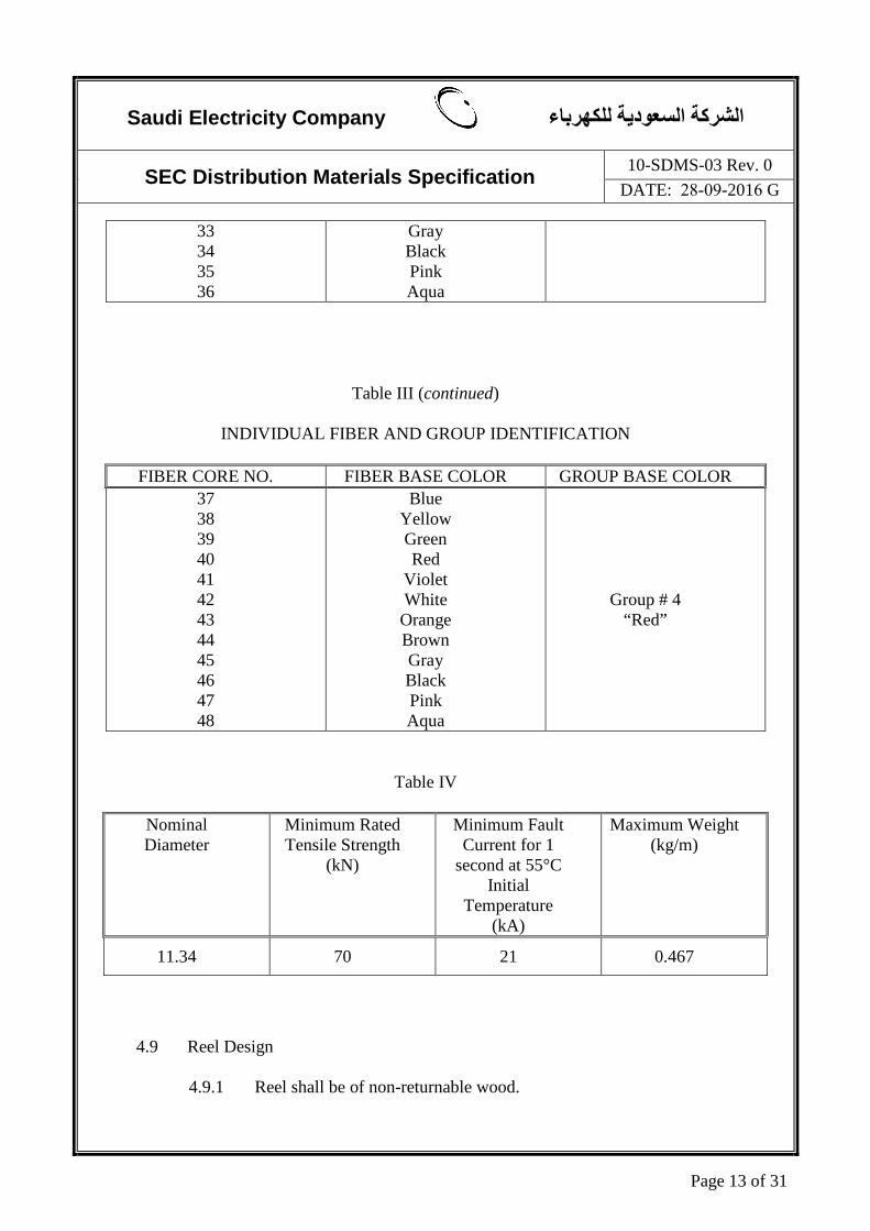
33 34 35 36
Gray Black Pink Aqua
Table III (continued)
INDIVIDUAL FIBER AND GROUP IDENTIFICATION
FIBER CORE NO. FIBER BASE COLOR GROUP BASE COLOR 37 38 39 40 41 42 43 44 45 46 47 48
Blue Yellow Green Red
Violet White Orange Brown Gray Black Pink Aqua
Group # 4 “Red”
Table IV
Nominal Diameter
Minimum Rated Tensile Strength
(kN)
Minimum Fault Current for 1
second at 55°C Initial
Temperature (kA)
Maximum Weight (kg/m)
11.34 70 21 0.467
4.9 Reel Design 4.9.1 Reel shall be of non-returnable wood.

Saudi Electricity Company الشركة السعودية للكھرباء
SEC Distribution Materials Specification 10-SDMS-03 Rev. 0
DATE: 28-09-2016 G
Page 14 of 31
4.9.2 The length of OPGW per reel shall be 4000 m with a permissible variation of ±5%, unless otherwise different lengths are required as per actual site requirements or as agreed between SEC and the manufacturer.
4.10 Markings
4.10.1 Each end of the composite OPGW in the reel shall have a non-corroding
tag identifying the following: a. Type of stranded metallic wire b. Size of stranded metallic wires c. Cross-sectional area of the composite OPGW d. Type of optical fiber e. Number of optical fiber f. Manufacturer’s name or trademark g. Year of manufacture
4.10.2 Composite OPGW reel shall be marked in legible and indelible letters
providing the following particulars: a. Manufacturer’s name and country of origin b. Year of manufacture c. Size and material of stranded metallic wire/number and type of
optical fiber d. Serial number e. Length and weight of composite OPGW on reel f. Gross weight g. Dimensions of reel h. Directions of rolling of reel i. SEC Stock No. / JO No. / Contract No. j. SEC Address and Purchase Order Number k. 10-SDMS-03, Rev.0
4.10.3 All markings shall appear on both sides of the reel. See Figure 1 for reel
marking location.
4.10.4 Composite OPGW reel identification shall include any additional information as required by the SEC shipping instructions.
Saudi Electricity Company الشركة السعودية للكھرباء
SEC Distribution Materials Specification 10-SDMS-03 Rev. 0
DATE: 28-09-2016 G
Page 15 of 31
5.0 TESTS
All test results shall be provided for review and acceptance by SEC.
The term ‘relevant standards’ referred hereunder relates to the group of standards listed in clause 3.0 to which the optical fiber is being supplied by the manufacturer.
5.1 Composite OPGW Tests
5.1.1 Type (Design) Tests
All type (design) tests prescribed in the relevant IEC, EIA/TIA, ASTM
or IEEE standards to which the material is being supplied shall be performed on the representative unit or on the first unit of every new design or rating to be supplied to SEC.
In lieu of the actual type (design) tests, certified test reports of type
(design) tests performed on an identical unit may be submitted to SEC for review and approval during the bidding stage.
The type (design) tests are as follows:
a. Cable Cut-off Wavelength Tests
The cut-off wavelength of the cabled fiber shall be less than or equal to 1250 nm and 1450 nm for dispersion un-shifted single-mode fiber and non-zero dispersion-shifted single-mode fiber, respectively. Measurement shall be as specified in the relevant standard or in accordance with EIA/TIA-455-170.
The cable sample shall be 20 m long with additional 1 m fiber ends, each having one 76 mm loop to simulate the splice organizer. (The total fiber length is 22 m including the two 1 m ends.)
b. Fluid Penetration Test
Water ingress tests 1 m (one meter) sample cable designed for water blocking shall be performed as specified in the relevant standard or in accordance with EIA/TIA-455-82B. No water shall leak through the open end of 1 m sample. If the first sample fails, one additional 1 m sample, taken from a section of cable adjacent to the first sample may be tested for acceptance. Water leaks from second sample shall constitute failure.

Saudi Electricity Company الشركة السعودية للكھرباء
SEC Distribution Materials Specification 10-SDMS-03 Rev. 0
DATE: 28-09-2016 G
Page 16 of 31
c. Compound Flow (Drip) Test
A 0.3 m sample of OPGW shall be tested. The sample shall be prepared as specified in the relevant standard or in accordance with EIA/TIA-455-81A.
The filling and flooding compound shall not flow (drip or leak) at 65°C.
d. Short Circuit Test
Short circuit test on OPGW shall be performed in accordance with IEEE 1138. The maximum fault current shall pass through the 10 m cable sample for at least 0.30 second fault duration while continuously monitoring the optical attenuation of the test fibers from at least 2 minutes before to at least 5 minutes after each current pulse. The testing ambient temperature shall be at least 55°C.
The acceptance criteria shall be as per IEEE 1138.
e. Aeolian Vibration Test
Aeolian vibration test shall be carried out on OPGW as specified in the relevant standard or in accordance with IEEE 1138.
The acceptance criteria shall be as per IEEE 1138.
f. Sheave Test
A sheave test shall be carried out as specified in the relevant standard or in accordance with IEEE 1138.
The acceptance criteria shall be as per IEEE 1138.
g. Crush Test and Impact Test
A crush and an impact tests shall be performed as specified in the relevant standard or in accordance with EIA-455-25A and EIA-455-41A.
A permanent or temporary increase in optical attenuation value greater than 0.1 dB change in sample at 1300 nm or 1550 nm for single-mode fibers shall constitute failure.

Saudi Electricity Company الشركة السعودية للكھرباء
SEC Distribution Materials Specification 10-SDMS-03 Rev. 0
DATE: 28-09-2016 G
Page 17 of 31
h. Creep Test
A creep test shall be performed on an OPGW sample approximately 10 m long in accordance with IEEE 1138. The cable shall be terminated at each end and a tension of at least 30% of UTS shall be applied for duration of at least 1000 h.
The elongation of the composite OPGW versus time shall be measured at suitable intervals and recorded. Elongation with time shall be in accordance with the requirements as specified in the relevant standard or in accordance with ASTM B398M or ASTM B415. Any permanent or temporary increase in optical attenuation greater than 0.2 dB/km at 1300 nm or 1550 nm for single-mode fibers shall constitute failure.
i. Stress-Strain Test
A stress-strain test shall be performed on cable sample as specified in the relevant standard or in accordance with IEEE 1138. Any visual damage to the conductor strands or permanent or temporary increase in optical attenuation greater than 0.2 dB/km at 1300 nm or 1550 nm for single-mode fibers shall constitute failure.
j. Temperature Cycling
Temperature cycling measurements shall be made as specified in the relevant standard or in accordance with EIA/TIA-455-3A, using a modified version of Test Condition B, -45°C to +85°C, two cycles.
The change in attenuation between extreme operational temperatures for un-shifted single-mode fibers shall not be greater than 0.2 dB/km. The attenuation change measurements shall be made at 1310 nm and 1550 nm.
k. Rated Strength Tests on Completed OPGW
The breaking strength of the completed OPGW shall not be less than the specified rated breaking strength of the OPGW unless the failure occurs in the gripping device. If the failure occurs in the grip, the test value must not be less than 90% of the specified rated breaking strength.
l. Salt Spray Corrosion Test

Saudi Electricity Company الشركة السعودية للكھرباء
SEC Distribution Materials Specification 10-SDMS-03 Rev. 0
DATE: 28-09-2016 G
Page 18 of 31
This test will be a 1000 hours salt spray test to be performed in accordance with the requirements of IEEE 1138 (latest edition). The test procedure shall be as per ASTM B117 or equivalent. In addition to the acceptance criteria of IEEE 1138, there shall be no signs of exposure of the base metal, pitting and porosity of the finish, cracking or delamination of components, abnormal nicks, cracks or scratches on surfaces.
5.1.2 Routine (Production) Tests
All routine (production) tests prescribed in the relevant IEC, EIA/TIA, ASTM or IEEE standards to which the material is being supplied shall be performed on all units prior to delivery to SEC.
Tests for mechanical and physical properties of concentric-lay stranded metallic wires shall be made before stranding.
a. Tests for aluminum-alloy wires shall be shown below.
i. All aluminum-alloy wires shall be capable of meeting the
bending properties as specified in the relevant standard or in accordance with ASTM B398M after stranding.
ii. The minimum tensile strengths shall not be less than 95% of
the tensile strengths specified for individual tests as specified in the relevant standard or in accordance with Table 1 of ASTM B398M.
b. Tests for aluminum-clad steel wires shall be as shown below.
i. The aluminum-clad steel wire shall withstand without fracture
not less than 20 twists in a length equivalent to 100 times the nominal diameter of the wire. The specimen shall be twisted by rotating on the wires at a rate of approximately 15 twists per minute in the same direction until fracture occurs.
ii. The aluminum-clad steel wires after twisting to destruction
shall not reveal any seams, pits, slivers or surface imperfections of sufficient magnitude to indicate inherent defects in the wire. Examination of the wire at the break shall show no separation of the aluminum from the steel.
c. Other required tests shall be performed as specified in the relevant
standard or in accordance with ASTM B415.

Saudi Electricity Company الشركة السعودية للكھرباء
SEC Distribution Materials Specification 10-SDMS-03 Rev. 0
DATE: 28-09-2016 G
Page 19 of 31
Tests for mechanical and physical properties of Central Fiber Optic unit shall be made before assembly.
d. Optical Acceptance Tests
Attenuation test shall be performed on each fiber of each individual reel as specified in the relevant standard or in accordance with EIA/TIA 455-61, Measurement of Cable Attenuation using an Optical Time Domain Reflectometer (OTDR).
Measurement shall be made from both directions and the results shall be averaged. Attenuation loss values exceeding those specified shall constitute failure.
5.2 Fiber Tests 5.2.1 Type (Design) Tests
All type (design) tests prescribed in the relevant IEC, EIA/TIA, ASTM or IEEE standards to which the material is being supplied shall be performed on the representative unit or on the first unit of every new design or rating to be supplied to SEC. In lieu of the actual type (design) tests, certified tests reports of type (design) tests performed on an identical unit shall be submitted, or the cable manufacturer shall submit reports in the form of batch test reports furnished by the core manufacturer, provided that the core supplied to SEC is out of the same batch and the core manufacturer is listed in the SEC approved list. All the required test reports shall be submitted to SEC for review and approval during the bidding stage. The type (design) tests are as follows: a. Attenuation Variation with Wavelength
The measurement shall be made as specified in the relevant standard or in accordance with EIA/TIA 455-78A. The spectral width of the source shall be less than 10 nm. The attenuation coefficient of un-shifted single-mode fibers for wavelengths between 1285 nm and 1300 nm shall not exceed the attenuation coefficient at 1300 nm by more than 0.1 dB/km.
b. Attenuation with Bending

Saudi Electricity Company الشركة السعودية للكھرباء
SEC Distribution Materials Specification 10-SDMS-03 Rev. 0
DATE: 28-09-2016 G
Page 20 of 31
Attenuation with bending measurements shall be made as specified in relevant standard or in accordance with Macrobending Sensitivity Technique at 1550 nm as per IEC 60793-1-C11. The two attenuation with bending requirements are measured by winding 100 turns of fiber on a collapsible reel or removable mandrel of 75 nm ±2 mm diameter and by wrapping a single turn of fiber around a 32 ± 0.5 mm diameter mandrel. Attenuation shall not exceed 0.5 dB at 1300 nm or 1550 nm.
c. Temperature Cycling Test Temperature cycling measurement shall be made as specified in the relevant standard or in accordance with EIA/TIA 455-3A, using Test Condition A, -45°C to +85°C, 2 cycles. The change in attenuation between extreme operational temperatures for single-mode fibers shall not be greater than 0.05 dB/km at 1300 nm and 1550 nm.
d. Attenuation at the Water Peak For un-shifted single-mode fiber, the attenuation coefficient at the water peak shall be as specified in ITU-G.652.
e. Chromatic Dispersion Dispersion measurements shall be made as specified in the relevant standard or in accordance with EIA/TIA 455-168A. For dispersion un-shifted single-mode fibers refer to Table I.
f. Mode Field Diameter Mode field diameter shall be measured as specified in the relevant standards or in accordance with EIA-455-174. The measurement wavelength as a minimum shall be 1310 ± 20 nm for dispersion un-shifted single mode fibers. The nominal mode field diameter (MFD) for dispersion un-shifted single-mode fibers shall be in accordance with Table I.
g. Concentric Error Core-to-Clad Concentricity Error measuremetns shall be made as specified in the relevant standard or in accordance with EIA/TIA 455-45B.

Saudi Electricity Company الشركة السعودية للكھرباء
SEC Distribution Materials Specification 10-SDMS-03 Rev. 0
DATE: 28-09-2016 G
Page 21 of 31
Concentricity error – the offset between the center of the core and the center of the cladding shall be < 1.0 micron.
h. Cladding Diameter and Non-Circularity Error Measurements shall be as specified in the relevant standard or in accordance with EIA/TIA 455-45B. Cladding Diameter – the cladding outside diameter shall be 125.0 microns ± 2.0% microns. Cladding Non-Circularity – the cladding non-circularity shall be < 2%.
i. Coating Diameter Coating diameter measurements shall be made as specified in the relevant standard or in accordance with EIA/TIA 455-55B. Coating Diameter – the nominal coating diameter for loose buffer shall be 250 microns.
j. Fiber Tensile Proof Test Individual fibers shall be proof tested as specified in the relevant standard or in accordance with EIA/TIA 455-31B. All fibers shall be subjected to a minimum proof stress of 0.35GN/m² for one second equivalent by the fiber manufacturer (100% testing).
5.2.2 Routine (Production) Tests
All routine (production) tests prescribed in the relevant IEC, EIA/TIA, ASTM or IEEE standards to which the material is being supplied shall be performed on all units prior to delivery to SEC. a. Attenuation Coefficient
The attenuation coefficient for un-shifted single-mode fiber shall be 0.45 dB/km or less at 1300 nm and 0.25 dB/km or less at 1550 nm wavelength and all measurements shall be made bi-directionally if accesible and the results shall be averaged.

Saudi Electricity Company الشركة السعودية للكھرباء
SEC Distribution Materials Specification 10-SDMS-03 Rev. 0
DATE: 28-09-2016 G
Page 22 of 31
All the traces (hard copies) must provide at least the following information other than the standard data provided by the OTDR. i. For the graphical representation of the trace, sufficient
acquisition time shall be set on ODTR for the straight line of the graph. Hazy lines due to insufficient acquisition time shall constitute failure.
ii. All traces shall clearly identify fiber number, binder-color (group identifier) and fiber color.
iii. All traces shall be furnished with the fiber-ID and the
drum/reel number and physical length of the cable ordered for cross reference.
b. Fiber Point Defects Attenuation uniformity shall be measured as specified in the relevant standard or in accordance with EIA/TIA 455-59. Measurement shall be made bi-directionally if accessible and the results shall be averaged. The attenuation of the fiber shall be distributed uniformly throughout its length such that there are no discontinuities in excess of 0.1 dB for single-mode fiber.
5.3 Field Acceptance Testing Upon receipt of the composite OPGW from the manufacturer, the purchaser shall at his option, perform acceptance test in order to verify that the optical characteristics of the fiber meet the order requirements and to determine if or not optical fibers have been damaged during shipment. The results of these tests and the manufacturer’s certified quality control information, which is attached to each reel, shall be compared to the fiber requirements specified in the purchase order. The tests shall be performed and documented by the use of Optical Time Domain Reflectometer (OTDR). The end of the cable shall be sealed after completion of these tests in order to prevent entry of moisture into the optical fiber. Test shall be performed from both ends and results shall be averaged. The following tests shall be performed as specified in the relevant standard or in accordance with EIA/TIA-455.

Saudi Electricity Company الشركة السعودية للكھرباء
SEC Distribution Materials Specification 10-SDMS-03 Rev. 0
DATE: 28-09-2016 G
Page 23 of 31
5.3.1 Fiber Continuity
Continuity checks of each fiber may be made to determine if or not any fiber is broken or any attenuation irregularities exist.
5.3.2 Attenuation Total attenuation for the entire reel length and attenuation per kilometer should be measured on each fiber. Attenuation uniformity shall meet the requirements of clause 5.2.2.b of this standard.
5.3.3 Fiber Length The fiber length may be measured using the OTDR. The index factor to be used in this measurement should be furnished by the fiber manufacturer. A check should be made to verify received reel numbers and lengths correspond to ordered quantities.
6.0 PACKING REQUIREMENTS 6.1 OPGW shall be tightly and uniformly wound onto reel(s) in layers. Reel lengths
shall be as specified in clause 4.9 above.
6.2 Reels shall be either wooden non-returnable or steel returnable type which conform to ANSI/AA 53-1981 or equal. Unless specified otherwise by the puchaser, the manufacturer will determine the size and type reel which will withstand normal shipping, handling, storage, and stringing operations without damage to the OPGW.
6.3 The drum and inside flanges shall be such that damage will not occur to the
OPGW during shipping, handling, storage, and stringing. This may be provided for by a layer of suitable material which is water resistant and will not absorb moisture. The outer layer of the OPGW shall be protected by a water resistance wrapping over the exposed surface to prevent dirt and grity material from coming in contact with the OPGW during shipment and storage.
6.4 Reels shall have wooden lagging attached to the flanges unless specified otherwise by the purchaser. Wood lagging should be similar to a Grade 3, cured and dressed, 50 x 100 mm Southern Pine lumber or equal. Lagging shall be attached to reels in such a manner where individual lagging strips will remain in place during normal shipment, handling, and storage.

Saudi Electricity Company الشركة السعودية للكھرباء
SEC Distribution Materials Specification 10-SDMS-03 Rev. 0
DATE: 28-09-2016 G
Page 24 of 31
6.5 The outer end of the OPGW shall be fastened to the inner surface of the reel flange a minimum of 25 mm below the wood lagging. The cable end shall be securely fastened to prevent the cable from becoming loose during shipment. Aminimum of 4 meter of the inner end of the OPGW shall be accessible for connection to optical measuring equipment without removing wood lagging or outer layer of protection. This length of cable shall be securely fastened and protected during shipment.
6.6 A seal shall be applied to each end of the OPGW to prevent the entrance of moisture into the optical fibers or the escape of filling compund during shipment and storage. Two (2) extra seals shall be shipped with each reel and should be accessible without removing lagging.
6.7 The manufacturer shall furnish at the time of shipment, a certified record of final quality control measured values for each fiber on each reel. This certification shall be attached to the outside flange of the reel in a weatherproof package or submitted by the vendor, seperately.
6.8 Each reel shall be marked on the outside flange to indicate the direction the reel
should be rolled during shipment in order to prevent loosening of the cable on the reel.
Figure 1 – REEL MARKING LOCATIONS

Saudi Electricity Company الشركة السعودية للكھرباء
SEC Distribution Materials Specification 10-SDMS-03 Rev. 0
DATE: 28-09-2016 G
Page 25 of 31
7.0 DATA SCHEDULE OPTICAL FIBER GROUND WIRE (OPGW)
(Sheet 1 of 7)
SEC Enquiry No. Date: SEC Purchase Order No.
Date:
or Contract No. SEC PTS No./Project Title with J.O. No.
REFERENCE SECTION NO.
DESCRIPTION
SEC SPECIFIED VALUES
VENDOR PROPOSED
VALUES
3.0 APPLICABLE CODES AND STANDARDS
Applicable Industry Standards *
4.0 DESIGN AND CONSTRUCTION REQUIREMENTS
4.3 Stranded Metallic Wires Number of Layers * Inner Layer: -Type of Metallic Wire * -Nominal Size of the Wire (mm) * -Thickness of Aluminum-Cladding (mm) * -Nominal Diameter of the Wire (mm) * -Minimum Breaking Strength of the Wire (kN) * -Nominal Diameter of Strand (mm) * -Direction of Lay Stranding * -Nominal Length of Lay (mm) *

Saudi Electricity Company الشركة السعودية للكھرباء
SEC Distribution Materials Specification 10-SDMS-03 Rev. 0
DATE: 28-09-2016 G
Page 26 of 31
7.0 DATA SCHEDULE OPTICAL FIBER GROUND WIRE (OPGW)
(Sheet 2 of 7)
REFERENCE SECTION NO.
DESCRIPTION
SEC SPECIFIED VALUES
VENDOR PROPOSED VALUES
Outer Layer: -Type of Metallic Wire * -Nominal Size of the Wire (mm) * -Thickness of Aluminum Coating (mm) * -Nominal Diameter of the Wire (mm) * -Minimum Breaking Strength of the Wire (kN) * -Nominal Diameter of Strand (mm) * -Direction of Lay Stranding * -Nominal Length of Lay * 4.4 Central Fiber Optical Unit Material Type * Tube: -Thickness (mm) * Channel Rod or Spacer (mm): * -Diameter * -Number of Grooves * -Thermo-Resistant Type * Filling Compound Type/Material * Structural Member Material 4.5 Optical Fiber Type of Optical Fiber Optical Fiber Operational Wavelength 1300/1550 nm for G.652D/G.655 Wavelength 1383-1625 nm for G.652D/G.655 Optical Fiber Material -Germanium Doped Silica -Glass/Pure Silica Glass Optical Fiber Material -Silica/Doped Silica Optical Fiber Mode Field Diameter (µm) *
Saudi Electricity Company الشركة السعودية للكھرباء
SEC Distribution Materials Specification 10-SDMS-03 Rev. 0
DATE: 28-09-2016 G
Page 27 of 31
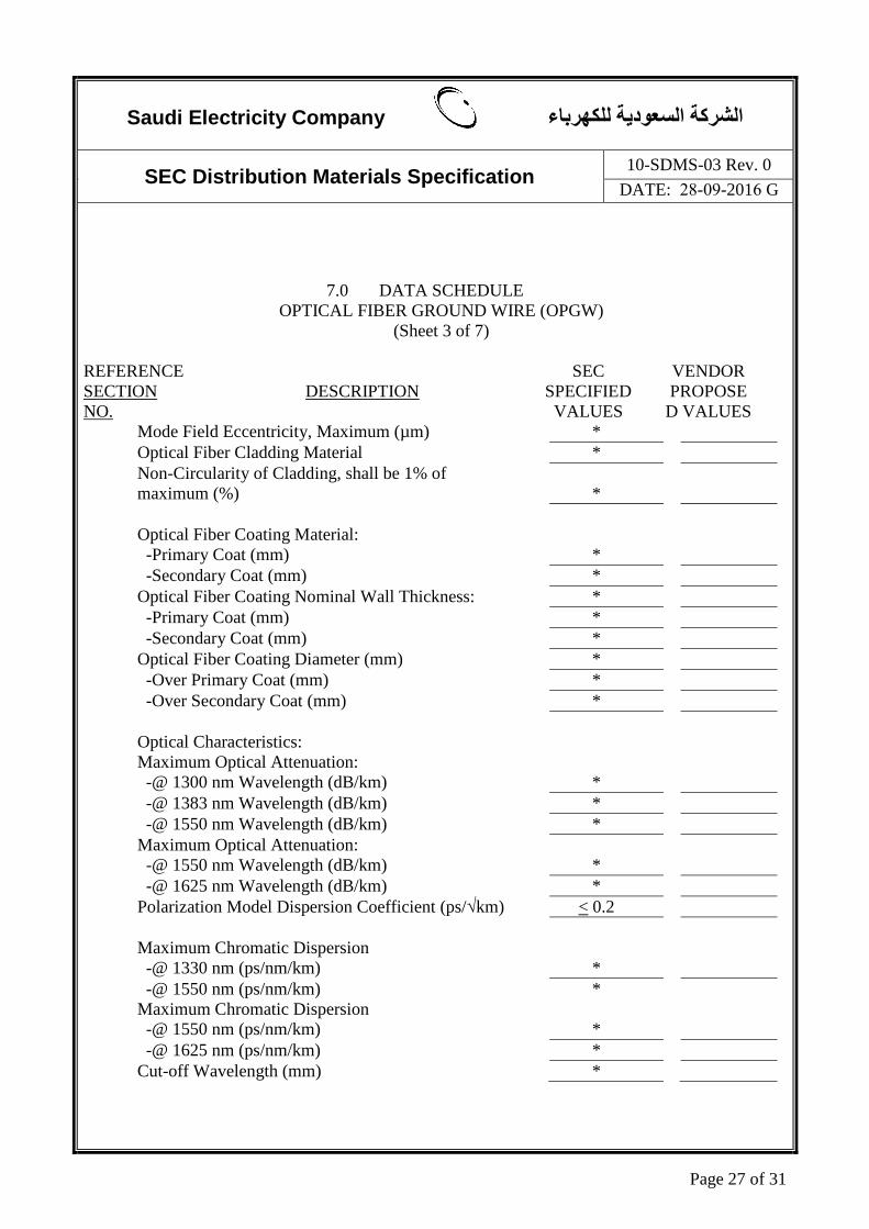
7.0 DATA SCHEDULE OPTICAL FIBER GROUND WIRE (OPGW)
(Sheet 3 of 7)
REFERENCE SECTION NO.
DESCRIPTION
SEC SPECIFIED VALUES
VENDOR PROPOSED VALUES
Mode Field Eccentricity, Maximum (µm) * Optical Fiber Cladding Material * Non-Circularity of Cladding, shall be 1% of
maximum (%) *
Optical Fiber Coating Material: -Primary Coat (mm) *
-Secondary Coat (mm) * Optical Fiber Coating Nominal Wall Thickness: * -Primary Coat (mm) * -Secondary Coat (mm) * Optical Fiber Coating Diameter (mm) * -Over Primary Coat (mm) * -Over Secondary Coat (mm) * Optical Characteristics: Maximum Optical Attenuation: -@ 1300 nm Wavelength (dB/km) * -@ 1383 nm Wavelength (dB/km) * -@ 1550 nm Wavelength (dB/km) * Maximum Optical Attenuation: -@ 1550 nm Wavelength (dB/km) * -@ 1625 nm Wavelength (dB/km) * Polarization Model Dispersion Coefficient (ps/√km) < 0.2 Maximum Chromatic Dispersion -@ 1330 nm (ps/nm/km) * -@ 1550 nm (ps/nm/km) * Maximum Chromatic Dispersion -@ 1550 nm (ps/nm/km) * -@ 1625 nm (ps/nm/km) * Cut-off Wavelength (mm) *

Saudi Electricity Company الشركة السعودية للكھرباء
SEC Distribution Materials Specification 10-SDMS-03 Rev. 0
DATE: 28-09-2016 G
Page 28 of 31
7.0 DATA SCHEDULE OPTICAL FIBER GROUND WIRE (OPGW)
(Sheet 4 of 7)
REFERENCE SECTION NO.
DESCRIPTION
SEC SPECIFIED VALUES
VENDOR PROPOSED VALUES
Operational Characteristics: Temperature Requirements w/o Optical Degradation:
Nominal Operating Temperature (°C) * Maximum Temperature Reached at Specified Fault
Current Condition Inside the Optical Unit (°C) *
Maximum Temperature w/o Optical or Mechanical Degradation for 1 second minimum (°C) *
Maximum Optical Loss Variation at Temperature Range of -5°C to +150°C (dB/km) *
4.7 Color Coding Color Coding of Each Fiber for a Group of Blue Twelve (12) Fibers Yellow [additional group of twelve (12) fibers has the Green Same sequence] Red Violet White Orange Brown Gray Black Pink Aqua Color Coding Group Identification -Group # 1 Blue -Group # 2 Yellow -Group # 3 Green -Group # 4 Red

Saudi Electricity Company الشركة السعودية للكھرباء
SEC Distribution Materials Specification 10-SDMS-03 Rev. 0
DATE: 28-09-2016 G
Page 29 of 31
7.0 DATA SCHEDULE OPTICAL FIBER GROUND WIRE (OPGW)
(Sheet 5 of 7)
REFERENCE SECTION NO.
DESCRIPTION
SEC SPECIFIED VALUES
VENDOR PROPOSED VALUES
4.8 Composite OPGW Maximum Tension that can be applied on Composite
OPGW w/o Optical or Mechanical Degradation (kN) *
Minimum Bending Radius of Composite OPGW (mm)
*
Cross Sectional Area of Metallic Part (mm²) * Maximum Nominal Diameter of Composite OPGW
(mm) 11.8
Minimum Rated Tensile Strength (kN) 70 Fault Current for 1 second at 55°C Initial Conductor
Temperature (kA) 21
Maximum Temperature Attained Following a Rated Short Circuit Current for 0.30 second Fault Duration:
-Strand (°C) * -Optical Unit (°C) * -Resistance (Ω) * Required Length per Reel (m) * Total Length Required (km) * Are matched sets of cable reel length required? Yes/No If “YES”, how many reels are required per set? * Tolerance in cable length of matched reel sets (m) * Length of composite OPGW per reel (m) * Gross weight per reel (kg) * Weight per unit length (kg/m) * Sag-Tension and Stress-Strain Data along with Sag
Chart No. *

Saudi Electricity Company الشركة السعودية للكھرباء
SEC Distribution Materials Specification 10-SDMS-03 Rev. 0
DATE: 28-09-2016 G
Page 30 of 31
7.0 DATA SCHEDULE OPTICAL FIBER GROUND WIRE (OPGW)
(Sheet 6 of 7)
REFERENCE SECTION NO.
DESCRIPTION
SEC SPECIFIED VALUES
VENDOR PROPOSED VALUES
5.0 TESTS Optional or Special Tests Requirements, if any

Saudi Electricity Company الشركة السعودية للكھرباء
SEC Distribution Materials Specification 10-SDMS-03 Rev. 0
DATE: 28-09-2016 G
Page 31 of 31
7.0 DATA SCHEDULE
OPTICAL FIBER GROUND WIRE (OPGW) (Sheet 7 of 7)
A. ADDITIONAL TECHNICAL INFORMATION OR FEATURES TO BE FURNISHED BY SEC:
B. ADDITIONAL SUPPLEMENTARY DATA OR FEATURES PROPOSED BY BIDDER/VENDOR/SUPPLIER/CONTRACTOR:
C.
OTHER PARTICULARS TO BE FILLED UP BY BIDDER/VENDOR/SUPPLIER/ CONTRACTOR:
D. LIST OF DEVIATIONS AND CLAUSES TO WHICH EXCEPTION IS TAKEN BY THE BIDDER / VENDOR / SUPPLIER (USE SEPARATE SHEET, IF NECESSARY):
Description Manufacturer of Material/Equipment
Vendor/Supplier
Name of Company
Location and Office
Address
Name & Signature of Authorized Representative
with Date
Official Seal / Stamp