1.0 introduction millscan dual g4 typical configuration millscan g4.pdf · 37 pricast tel: +34 93...
TRANSCRIPT

37
PRICASTTel: +34 93 439 03 13 Fax: +34 93 419 87 71 [email protected] www.pricast.es page 1 of 6
(2) 2 conductor cables or (1) 4 conductor cable
Foil shield Drain wire attached to ground
Polyethylene sleeve or similar
Copper conductor 16 – 20 AWG (16 AWG preferred) 1.5 – 0.5mm (1.25mm preferred)
4-‐20mA Cable
110-‐240 VAC
50/60 Hz
4-‐20mA Sensor Outputs(2) Two Conductor Cables or (1) Four Conductor Cable
Sensor cables and sensorssensor #1: 10 meterssensor #2: 30 meters(supplied by DCL)
Pipe stand 4 in. (10.2 cm) diameter
or similar
1.0 Introduction MillScan Dual G4 Typical ConfigurationA two channel vibration monitoring system consists of a MillScan Dual G4 unit and two magnetically mounted sensors. One sensor is placed on the inlet bearing housing while the second sensor is then placed on the outlet bearing housing. The sensor cable lengths are 10 meters (~30 ft.) and 30 meters (~90 ft.) long. The MillScan Dual therefore must be placed within 10 meters (30 ft.) of the bearing housing that has the shortest sensor cable. This can be either the inlet or the outlet side.
In addition to the two sensor cables attached to the MillScan Dual, there are three other cables to connect to the box: The first is AC power (90-230 VAC, 50 or 60 Hz, 0.5 Amp) which must be supplied by the plant. The second and third cables are twisted pair 4-20mA output cables (max. distance 1Km, ~3000 ft.) that also must be supplied by the plant. See Figure 1.
The 4-20mA outputs correspond to two distinct fill level signals corresponding to the inlet and discharge chamber fill levels on a two chamber mill. On a single chamber mill, both ends are still monitored so that a blockage at the outlet can quickly be observed. Also, the plant can chose which sensor they feel will be most suited for auto control or an average of the two sensors. The two sensors correspond to a fill level as follows. 4mA is empty (0%), 20mA is full (100%). These two cables are two conductors each and can be combined into one cable containing four conductors.
Figure 1. MillScan Dual G4 Typical Installation
Vibration measurements are directly obtained from the bearing housing on both the inlet & outlet sides of the mill. In Figure 2 a typical inlet set-up is shown. This signal has been found to be highly stable and excellent for auto control of the mill. It essentially is an integration (sum) of all the grinding

37
vibration on that particular side of the mill, and is much less susceptible to material variations found with a microphone placed nearby the mill.
Figure 2. Typical Sensor Placement
2.0 Basic Physical Dimensions
Vibration Sensors (2 Total)
cylindrical 3”/76.2 mm height x 3”/76.2 mm wide ;magnetic mount, 10m/30 ft., 30m/90 ft.
MillScan Dual G4 Unit
overall dimension 11.7”/280mm high x 9.9”/250mm wide x 4.7”/122mm deep ;bracket & screw mounted
3.0 Electrical & Cabling Requirements
(Vibration Sensors ;no plant requirements, powered by MillScan Dual (10 & 50 meter cables)
MillScan Dual AC Power ;90-230 VAC, 50/60 Hz, 0.5 Amp, plant must provide
(2) 4-20 mA Outputs ;each cable consists of 2 conductors, 24-16 gauge (16 gauge ;preferred)/1.5-0.5 mm diameter (1.25 mm dia. preferred) ;3000 ft./1000 meter maximum cable distance
MillScan Dual G4
90 – 240 VAC 50/60 Hz
Inlet 4-20 mA (1000m/3000ft max)Outlet 4-20 mA (1000m/3000ft max)
outletbearing housing
feed
re-circulation
inletbearinghousing
Vibration Sensor Vibe Sensor
discharge
PRICASTTel: +34 93 439 03 13 Fax: +34 93 419 87 71 [email protected] www.pricast.es page 2 of 6

37
4.0 Product Photos, Inlet & Outlet Fixed Position Sensors and Main Unit
PRICASTTel: +34 93 439 03 13 Fax: +34 93 419 87 71 [email protected] www.pricast.es page 3 of 6
37
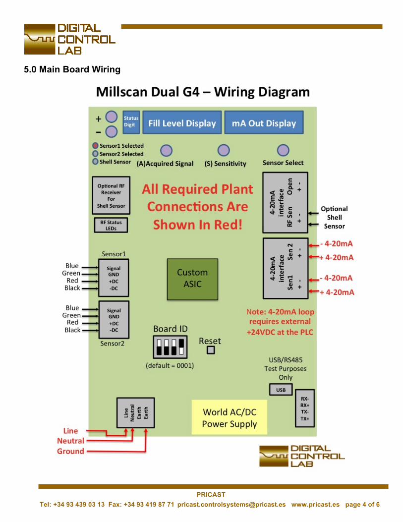
5.0 Main Board Wiring
PRICASTTel: +34 93 439 03 13 Fax: +34 93 419 87 71 [email protected] www.pricast.es page 4 of 6

37
6.0 Installation Process
Installation can be performed very quickly in a temporary manner initially and then made more permanent later. Here is a short summary of the process:
1. A vibration sensor is placed on the side of the bearing housing where balls strike the wall of the millfor both the inlet and discharge bearing housings.
2. The MillScan Dual unit is placed 15-30 ft away from the shortest sensor and powered by anextension cord. Note: The extension cord is then swapped out with metal conduit at a later date.
3. 4-20mA cables are then run from the MillScan Dual unit to the electrical room (MCC). The 4-20mAsignals are connected to two PLC inputs and variables are created in the control room software to view and create historical trending for the inlet & discharge fill level signals.
4. The unit is calibrated at the box for both channels. Typically 5 minutes for each sensor.
7.0 Items to Have Ready In Advance of MillScan Dual Commissioning
1. A standard 110V AC extension cable running to the bearing housing to power the DSP.
2. *Two 4-20mA inputs set up in the PLC in your electrical room with corresponding variables set up in your control room process monitoring program. Note: Loop power (24V DC) must be provided by the PLC to power the MillScan Dual 4-20mA outputs.
3. In addition to the variables (vibration fill level 4-20mA signals) being set up in your control software,we also want to have the ability to switch over to automatic control using these signals. *In other words, once we have the system calibrated, we want to immediately test automatic vibration control instead of your current control method (mill power, elevator amps, microphone ears, etc.) Please have your control software ready to switch over and run vibration signal mill control. This is very important and should be ready before system installation.
4-20mA connections
PRICASTTel: +34 93 439 03 13 Fax: +34 93 419 87 71 [email protected] www.pricast.es page 5 of 6
37
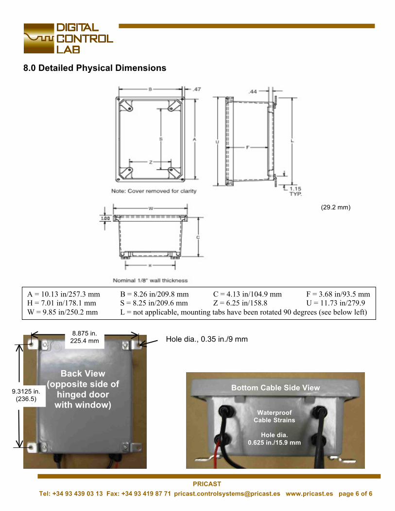
8.0 Detailed Physical Dimensions
A = 10.13 in/257.3 mm B = 8.26 in/209.8 mm C = 4.13 in/104.9 mm F = 3.68 in/93.5 mm H = 7.01 in/178.1 mm S = 8.25 in/209.6 mm Z = 6.25 in/158.8 U = 11.73 in/279.9 W = 9.85 in/250.2 mm L = not applicable, mounting tabs have been rotated 90 degrees (see below left)
(29.2 mm)
Back View (opposite side of
hinged door with window)
9.3125 in. (236.5) mm)
8.875 in. 225.4 mm Hole dia., 0.35 in./9 mm
Bottom Cable Side View
Waterproof Cable Strains
Hole dia. 0.625 in./15.9 mm
PRICASTTel: +34 93 439 03 13 Fax: +34 93 419 87 71 [email protected] www.pricast.es page 6 of 6