10 compound power miter saw - mike's tools · 3 additional safety rules for miter saws 1. do...
TRANSCRIPT

10" CompoundPower Miter Saw
(Model MS350)
INS
TRU
CTIO
NM
AN
UA
L
PART NO. 906068 - 05-30-02Copyright © 2002 Delta Machinery
ESPAÑOL: PÁGINA 21To learn more about DELTA MACHINERY visit our website at: www.deltamachinery.com.For Parts, Service, Warranty or other Assistance,
please call 1-800-223-7278 (In Canada call 1-800-463-3582).

2
GENERAL SAFETY RULESWoodworking can be dangerous if safe and proper operating procedures are not followed. As with all machinery, thereare certain hazards involved with the operation of the product. Using the machine with respect and caution willconsiderably lessen the possibility of personal injury. However, if normal safety precautions are overlooked or ignored,personal injury to the operator may result. Safety equipment such as guards, push sticks, hold-downs, featherboards,goggles, dust masks and hearing protection can reduce your potential for injury. But even the best guard won’t makeup for poor judgment, carelessness or inattention. Always use common sense and exercise caution in the workshop.If a procedure feels dangerous, don’t try it. Figure out an alternative procedure that feels safer. REMEMBER: Yourpersonal safety is your responsibility.
This machine was designed for certain applications only. Delta Machinery strongly recommends that this machine notbe modified and/or used for any application other than that for which it was designed. If you have any questions relativeto a particular application, DO NOT use the machine until you have first contacted Delta to determine if it can or shouldbe performed on the product.
Technical Service ManagerDelta Machinery4825 Highway 45 NorthJackson, TN 38305
(IN CANADA: 505 SOUTHGATE DRIVE, GUELPH, ONTARIO N1H 6M7)
WARNING: FAILURE TO FOLLOW THESE RULES MAY RESULT IN SERIOUS PERSONAL INJURY
1. FOR YOUR OWN SAFETY, READ INSTRUCTIONMANUAL BEFORE OPERATING THE TOOL. Learn the tool’sapplication and limitations as well as the specific hazardspeculiar to it.
2. KEEP GUARDS IN PLACE and in working order.3. ALWAYS WEAR EYE PROTECTION . Wear safety
glasses. Everyday eyeglasses only have impact resistantlenses; they are not safety glasses. Also use face or dustmask if cutting operation is dusty. These safety glassesmust conform to ANSI Z87.1 requirements. NOTE:Approved glasses have Z87 printed or stamped on them.
4. REMOVE ADJUSTING KEYS AND WRENCHES. Formhabit of checking to see that keys and adjusting wrenches areremoved from tool before turning it “on”.
5. KEEP WORK AREA CLEAN. Cluttered areas andbenches invite accidents.
6. DON’T USE IN DANGEROUS ENVIRONMENT. Don’t usepower tools in damp or wet locations, or expose them to rain.Keep work area well-lighted.
7. KEEP CHILDREN AND VISITORS AWAY. All childrenand visitors should be kept a safe distance from work area.
8. MAKE WORKSHOP CHILDPROOF – with padlocks,master switches, or by removing starter keys.
9. DON’T FORCE TOOL. It will do the job better and be saferat the rate for which it was designed.10. USE RIGHT TOOL. Don’t force tool or attachment to do ajob for which it was not designed.11. WEAR PROPER APPAREL. No loose clothing, gloves,neckties, rings, bracelets, or other jewelry to get caught inmoving parts. Nonslip footwear is recommended. Wearprotective hair covering to contain long hair.12. SECURE WORK. Use clamps or a vise to hold work whenpractical. It’s safer than using your hand and frees both handsto operate tool.13. DON’T OVERREACH. Keep proper footing and balanceat all times.14. MAINTAIN TOOLS IN TOP CONDITION. Keep toolssharp and clean for best and safest performance. Followinstructions for lubricating and changing accessories.15. DISCONNECT TOOLS before servicing and whenchanging accessories such as blades, bits, cutters, etc.16. USE RECOMMENDED ACCESSORIES. The use ofaccessories and attachments not recommended by Delta maycause hazards or risk of injury to persons.
17. REDUCE THE RISK OF UNINTENTIONAL STARTING.Make sure switch is in “OFF” position before plugging in powercord. In the event of a power failure, move switch to the“OFF” position.18. NEVER STAND ON TOOL. Serious injury could occur ifthe tool is tipped or if the cutting tool is accidentally contacted.19. CHECK DAMAGED PARTS. Before further use of thetool, a guard or other part that is damaged should be carefullychecked to ensure that it will operate properly and perform itsintended function – check for alignment of moving parts,binding of moving parts, breakage of parts, mounting, and anyother conditions that may affect its operation. A guard or otherpart that is damaged should be properly repaired or replaced.20. DIRECTION OF FEED. Feed work into a blade or cutteragainst the direction of rotation of the blade or cutter only.21. NEVER LEAVE TOOL RUNNING UNATTENDED. TURNPOWER OFF. Don’t leave tool until it comes to a completestop.22. STAY ALERT, WATCH WHAT YOU ARE DOING, ANDUSE COMMON SENSE WHEN OPERATING A POWERTOOL. DO NOT USE TOOL WHILE TIRED OR UNDERTHE INFLUENCE OF DRUGS, ALCOHOL, ORMEDICATION. A moment of inattention while operatingpower tools may result in serious personal injury.23. MAKE SURE TOOL IS DISCONNECTED FROM POWERSUPPLY while motor is being mounted, connected orreconnected.24. THE DUST GENERATED by certain woods and woodproducts can be injurious to your health. Always operatemachinery in well ventilated areas and provide for proper dustremoval. Use wood dust collection systems wheneverpossible.
25. WARNING: SOME DUST CREATED BY POWERSANDING, SAWING, GRINDING, DRILLING, AND OTHERCONSTRUCTION ACTIVITIES contains chemicals knownto cause cancer, birth defects or other reproductive harm.Some examples of these chemicals are:· lead from lead-based paints,· crystalline silica from bricks and cement and other
masonry products, and· arsenic and chromium from chemically-treated lumber. Your risk from these exposures varies, depending on howoften you do this type of work. To reduce your exposure tothese chemicals: work in a well ventilated area, and workwith approved safety equipment, such as those dust masksthat are specially designed to filter out microscopic particles.

3
ADDITIONAL SAFETY RULES FORMITER SAWS
1. DO NOT OPERATE THIS MACHINE UNTIL it isassembled and installed according to theinstructions.
2. OBTAIN ADVICE from your supervisor, instructor,or another qualified person if you are not familiarwith the operation of this machine.
3. FOLLOW ALL WIRING CODES and recommendedelectrical connections.
4. USE ONLY CROSS-CUTTING SAW BLADES. Whenusing carbide-tipped blades, make sure they have anegative hook angle. Do not use blades with deep gulletsas they can deflect and contact guard.
5. DO NOT perform any operation freehand. Secure orclamp workpiece firmly against fence.
6. KEEP HANDS OUT OF PATH of saw blade. If theworkpiece you are cutting would cause your hand tobe within the hazard zone of the saw blade, theworkpiece should be clamped in place beforemaking cut.
7. BE SURE blade is sharp, runs free, and is free ofvibration.
8. ALLOW the motor to come up to full speed beforestarting cut.
9. KEEP motor air slots clean and free of chips.
10. ALWAYS MAKE SURE all clamp handles are tightbefore cutting, even if the table is positioned in oneof the positive stops.
11. BE SURE blade and flanges are clean and that arborscrew is tightened securely.
12. USE only blade flanges specified for your saw.
13. USE PROPER BLADE SIZE and type.
14. NEVER apply lubricants to the blade when it isrunning.
15. ALWAYS check the blade for cracks or damagebefore operation. Replace cracked or damagedblade immediately.
16. NEVER reach around or behind saw blade.
17. MAKE SURE blade is not contacting workpiecebefore switch is turned on.
18. NEVER lock the switch in the “ON” position.
19. AFTER COMPLETING CUT, release power switchand wait for coasting blade to stop before returningsaw to raised position.
20. TURN OFF tool and wait for saw blade to stopbefore moving workpiece or changing settings.
21. DO NOT remove jammed or cut-off pieces until bladehas stopped.
22. NEVER cut ferrous metals or masonry.
23. NEVER recut small pieces.
24. PROPERLY SUPPORT LONG OR WIDE work-pieces.
25. NEVER use the miter saw in an area with flammableliquids or gases.
26. NEVER use solvents to clean plastic parts. Solventscould possibly dissolve or otherwise damage thematerial. Only a soft damp cloth should be used toclean plastic parts.
27. TURN THE MACHINE “OFF” AND DISCONNECTTHE MACHINE from the power source beforeinstalling or removing accessories, before adjustingor changing set-ups, or when making repairs.
28. TURN THE MACHINE “OFF”, disconnect themachine from the power source, and clean thetable/work area before leaving the machine. LOCKTHE SWITCH IN THE “OFF” POSITION to preventunauthorized use.
29. ADDITIONAL INFORMATION regarding the safeand proper operation of this tool is available from thePower Tool Institute, 1300 Summer Avenue,Cleveland, OH 44115-2851. Information is alsoavailable from the National Safety Council, 1121Spring Lake Drive, Itasca, IL 60143-3201. Pleaserefer to the American National Standards InstituteANSI 01.1 Safety Requirements for WoodworkingMachines and the U.S. Department of Labor OSHA1910.213 Regulations.
WARNING: FAILURE TO FOLLOW THESE RULES MAY RESULT IN SERIOUS PERSONAL INJURY.
SAVE THESE INSTRUCTIONS. Refer to them often
and use them to instruct others.

4
POWER CONNECTIONSA separate electrical circuit should be used for your machines. This circuit should not be less than #12 wire and shouldbe protected with a 20 Amp time lag fuse. If an extension cord is used, use only 3-wire extension cords which have 3-prong grounding type plugs and matching receptacle which will accept the machine’s plug. Before connecting themotor to the power line, make sure the switch is in the “OFF” position and be sure that the electric current is of thesame characteristics as indicated on the machine. All line connections should make good contact. Running on lowvoltage will damage the motor.
WARNING: DO NOT EXPOSE THE MACHINE TO RAIN OR OPERATE THE MACHINE IN DAMP LOCATIONS.
MOTOR SPECIFICATIONSYour machine is wired for 120 volt, 60 HZ alternating current. Before connecting the machine to the power source,make sure the switch is in the “OFF” position.
GROUNDING INSTRUCTIONSWARNING: THIS MACHINE MUST BE GROUNDED WHILE IN USE TO PROTECT THE OPERATOR FROMELECTRIC SHOCK.
Fig. A Fig. B
GROUNDED OUTLET BOX
CURRENTCARRYING
PRONGS
GROUNDING BLADEIS LONGEST OF THE 3 BLADES
GROUNDED OUTLET BOX
GROUNDINGMEANS
ADAPTER
2. Grounded, cord-connected machines intended foruse on a supply circuit having a nominal rating lessthan 150 volts:
If the machine is intended for use on a circuit that has anoutlet that looks like the one illustrated in Fig. A, themachine will have a grounding plug that looks like the plugillustrated in Fig. A. A temporary adapter, which looks likethe adapter illustrated in Fig. B, may be used to connectthis plug to a matching 2-conductor receptacle as shownin Fig. B if a properly grounded outlet is not available. Thetemporary adapter should be used only until a properlygrounded outlet can be installed by a qualified electrician.The green-colored rigid ear, lug, and the like, extendingfrom the adapter must be connected to a permanentground such as a properly grounded outlet box. Wheneverthe adapter is used, it must be held in place with a metalscrew.
NOTE: In Canada, the use of a temporary adapter is notpermitted by the Canadian Electric Code.
WARNING: IN ALL CASES, MAKE CERTAIN THE RECEPTACLE IN QUESTION IS PROPERLY
GROUNDED. IF YOU ARE NOT SURE, HAVE AQUALIFIED ELECTRICIAN CHECK THE RECEPTACLE.
1. All grounded, cord-connected machines:
In the event of a malfunction or breakdown, groundingprovides a path of least resistance for electric current toreduce the risk of electric shock. This machine isequipped with an electric cord having an equipment-grounding conductor and a grounding plug. The plug mustbe plugged into a matching outlet that is properly installedand grounded in accordance with all local codes andordinances.
Do not modify the plug provided - if it will not fit the outlet,have the proper outlet installed by a qualified electrician.
Improper connection of the equipment-groundingconductor can result in risk of electric shock. Theconductor with insulation having an outer surface that isgreen with or without yellow stripes is the equipment-grounding conductor. If repair or replacement of theelectric cord or plug is necessary, do not connect theequipment-grounding conductor to a live terminal.
Check with a qualified electrician or service personnel ifthe grounding inst ruct ions are not complete lyunderstood, or if in doubt as to whether the machine isproperly grounded.
Use only 3-wire extension cords that have 3-pronggrounding type plugs and matching 3-conductorreceptacles that accept the machine’s plug, as shown inFig. A.
Repair or replace damaged or worn cord immediately.

Use proper extension cords. Make sure your extension cord is in good condition and is a 3-wire extension cord whichhas a 3-prong grounding type plug and matching receptacle which will accept the machine’s plug. When using anextension cord, be sure to use one heavy enough to carry the current of the machine. An undersized cord will causea drop in line voltage, resulting in loss of power and overheating. Fig. C shows the correct gauge to use depending onthe cord length. If in doubt, use the next heavier gauge. The smaller the gauge number, the heavier the cord.
EXTENSION CORDS
OPERATING INSTRUCTIONSFOREWORD
Delta Model MS350 is a 10" Compound Power Miter Saw designed to cut wood, plastic, and aluminum. Compoundangle and bevel cutting are easy and accurate. It can crosscut up to 5-3/4" x 2-3/8"at the 90 degree position, miter at45 degrees, both left and right 4-1/8" x 2-3/8", bevel at 45 degrees left 5-1/2" x 1-9/16", and compound 45 x 45 degrees4-1/8" x 1-9/16". It has positive miter stops at 0, 22.5, 31.62, and 45 degrees both left and right, and bevel stops at 0and 45 degrees adjustable.
UNPACKING AND CLEANINGCarefully unpack the machine and all loose items from the shipping container(s). Remove the protective coating fromall unpainted surfaces. This coating may be removed with a soft cloth moistened with kerosene (do not use acetone,gasoline or lacquer thinner for this purpose). After cleaning, cover the unpainted surfaces with a good quality householdfloor paste wax.
5
Fig. C
MINIMUM GAUGE EXTENSION CORDRECOMMENDED SIZES FOR USE WITH STATIONARY ELECTRIC MACHINES
Ampere Total Length Gauge ofRating Volts of Cord in Feet Extension Cord
0-6 120 up to 25 18 AWG0-6 120 25-50 16 AWG0-6 120 50-100 16 AWG0-6 120 100-150 14 AWG
6-10 120 up to 25 18 AWG6-10 120 25-50 16 AWG6-10 120 50-100 14 AWG6-10 120 100-150 12 AWG
10-12 120 up to 25 16 AWG10-12 120 25-50 16 AWG10-12 120 50-100 14 AWG10-12 120 100-150 12 AWG
12-16 120 up to 25 14 AWG12-16 120 25-50 12 AWG12-16 120 GREATER THAN 50 FEET NOT RECOMMENDED

6
CARTON CONTENTSRemove the miter saw and all loose items from thecarton. IMPORTANT: CARRYING THE MACHINE BYTHE SWITCH HANDLE WILL CAUSE MISALIGNMENT.ALWAYS LIFT THE MACHINE BY THE BASE OR BYTHE CARRYING HANDLE (See Fig. 29C). Fig. 2illustrates the machine and all loose items after theyhave been removed from the carton.
1 - Miter Saw
2 - Dust Bag
3 - Wrenches for changing the blade
4 - Clamp
WARNING: FOR YOUR OWN SAFETY, DO NOT CONNECT THE MITER SAW TO THE POWER SOURCEUNTIL THE MACHINE IS COMPLETELY ASSEMBLED AND YOU READ AND UNDERSTAND THE ENTIREOWNER’S MANUAL.
ROTATING TABLE TO 90DEGREE POSITION1. Loosen table lock handle (A) Fig. 3 one or two turnsand depress index lever (B).
2. Rotate table to the left until index stop engages withthe 90 degree positive stop (Fig. 4). Tighten table lockhandle (A).
A
Fig. 2
2
4
3
1
Fig. 3
Fig. 4
A
B

7
Fig. 5 Fig. 6
Fig. 7
FASTENING MACHINE TOSUPPORTING SURFACE
MOVING CUTTINGHEAD TO THE UP POSITION1. Push down on switch handle (A) Fig. 5 and pull out cuttinghead lock knob (B).
2. Move the cuttinghead (C) to the up position (Fig. 6).
ATTACHING DUST BAG1. Attach dust bag (A) Fig. 7 to the dust spout (B)making sure the wire ring (C) is engaged between theridges in the spout.
Before operating your compound miter saw, make sureit is firmly mounted to a sturdy workbench or othersupporting surface. Four holes are provided, two of whichare shown at (A) Fig. 8.
When frequently moving the saw from place to place, wesuggest that the saw be mounted to a 3/4″ piece ofplywood. Use “C” clamps to secure the plywood to asupporting surface.
A
B
Fig. 8
A
C
B
AA
C

8
OPERATING CONTROLS AND ADJUSTMENTS
STARTING AND STOPPING MACHINETo start the machine, depress switch trigger (A) Fig. 11. To stop the machine, release the switch trigger. This miter sawis equipped with an automatic electric blade brake. As soon as the switch trigger (A) Fig. 11 is released, the electricbrake is activated and stops the blade in seconds.
WARNING: A turning saw blade can be hazardous. After completing cut, release the switch trigger (A) Fig. 11 toactivate blade brake. Keep cuttinghead down until blade has come to a complete stop.
WARNING: The torque developed during braking may loosen the arbor screw. The arbor screw should bechecked periodically and tightened if necessary.
LOCKING SWITCH IN THE “OFF” POSITIONIMPORTANT: When the machine is not in use, the switch should be locked in the “OFF” position to preventunauthorized use, using a padlock (B) Fig. 12 with a 3/16" diameter shackle.
Fig. 10
Fig. 12
B
A
Fig. 11
A
1. A work clamp (A) Fig. 10 is supplied with thismachine. Use this clamp, especially with short work-pieces. Never allow your hands to be in the “HazardZone”.2. Two holes (B) Fig. 9 are provided in the base of themiter saw, enabling you to use the clamp (A) Fig. 10 oneither the right or left hand side of the machine.
WARNING: Keep hands out of path of sawblade. If necessary, clamp the workpiece in placebefore making cut.
WARNING: The area inside the two redlines (A) Fig. 9 on the table is designated asa hazard zone. Never place your handsinside this area while the tool is beingoperated.
TABLE HAZARD AREA
Fig. 9
A
B B

ROTATING TABLE FOR MITER CUTTINGYour miter saw will cut any angle from a straight 90 degree cutto 47 degrees right and left. Loosen lock handle (A) Fig. 13 oneor two turns, depress index lever (B), and move the table to thedesired angle. TIGHTEN LOCK HANDLE (A).
The miter saw is equipped with positive stops at the 0, 22.5,31.62, and 45 degree right and left positions. Loosen lockhandle (A) Fig. 13, and move the table until the bottom of theindex lever (B) engages into one of the positive stops, three ofwhich are shown at (C). TIGHTEN LOCK HANDLE (A). Todisengage the positive stop, loosen lock handle and depressindex lever (B).
In addition, a triangle indicator and positive stop are provided onthe miter scale at the 31.62 degrees right and left miter positionsfor cutting crown moulding. (Refer to the “CUTTING CROWN MOULDING” section of this manual).
9
Fig. 14
POINTER AND SCALEAn indicator (E) Fig. 14 shows the actual angle of cut.Each line on the scale (F) represents 1/2 degree. Whenthe indicator is moved from one line to the next on thescale, the angle of cut is changed by 1/2 degree.
ADJUSTING POINTERIf it becomes necessary to adjust the indicator (E) Fig.14, loosen screws (G), adjust the indicator (E), andtighten screws.
B
AC
Fig. 13
E
GF
IMPORTANT: ALWAYS TIGHTEN LOCK HANDLE (A) FIG. 13 BEFORE CUTTING.
Fig. 15
Fig. 16
D
C
TOOL STORAGEConvenient storage spaces for both the supplied bladeremoval wrench and the supplied hex wrench arelocated on the machine.
The hex wrench storage (A) Fig. 15 is located immedi-ately behind the sliding fence (B).
The blade removal wrench storage (C) Fig. 16 is locatedbehind the opposite fence (D).
A
B

10
Fig. 20
TILTING CUTTINGHEAD FORBEVEL CUTTINGThe cuttinghead of your compound miter saw can be tilted tocut any bevel angle from a 90 degree straight cut off to a 45degree left bevel angle. Push lock handle (A) Fig. 18 in andturn counter-clockwise. Tilt cuttinghead to the desired angle,and tighten lock handle (A) Fig. 18.Positive stops are provided to rapidly position the sawblade at 90 and 45 degrees to the table. Refer to the sectionof this manual titled “ADJUSTING 90 AND 45 DEGREEBEVEL STOPS.” The bevel angle of the cuttinghead isdetermined by the position of the pointer (C) Fig. 19 on thescale (D).In addition, a triangle indicator is provided on the bevel scaleat the 33.85 degree bevel angle for cutting crown moulding.Refer to the “CUTTING CROWN MOULDING” section of thismanual.
Fig. 21
ADJUSTING FENCE90 DEGREES TO BLADEIf the fence (A) Fig. 20 is removed from the saw, adjust it after replacement so that it is 90 degrees to the blade asfollows:1. DISCONNECT MACHINE FROM POWER SOURCE.2. Place one end of the square (B) Fig. 20 against the fence (A) and the other end against the blade.3. To adjust, loosen the four screws (C) Fig. 21, and adjust fence 90 degrees to the blade. NOTE: Two of the screwsare located under the sliding fence. Remove lock knob (D) Fig. 21 and sliding fence (E) to gain access to the screws. 4. Tighten the four screws (C) Fig. 21.5. Replace sliding fence and lock knob removed in STEP 3.
A
B
C
C
Fig. 18
LOCKING CUTTINGHEADIN THE DOWN POSITIONWhen transporting the saw, the cuttinghead should always belocked in the down position. Lower the cuttinghead (A) Fig. 17,and push in cuttinghead lock knob (B) until it engages with holein cuttinghead. IMPORTANT: CARRYING THE MACHINE BYTHE SWITCH HANDLE WILL CAUSE MISALIGNMENT.ALWAYS LIFT THE MACHINE BY THE BASE OR BY THECARRYING HANDLE (See Fig. 29C).
A
B
Fig. 17
Fig. 19
A
C
D
E D

ADJUSTING DOWNWARD TRAVEL OF SAW BLADE1. DISCONNECT MACHINE FROM POWER SOURCE.2. The downward travel of the saw blade should be limited to prevent the saw blade from contacting any metalsurfaces of the machine. This adjustment is made by loosening lockknob (A) Fig. 22, and turning adjusting screw (B) inor out.3. Lower the blade as far as possible. Rotate the blade by hand to make certain the teeth do not contact any metalsurfaces and adjust if necessary.4. After the downward travel of the saw blade has been adjusted, tighten lockknob (A) Fig. 22.
11
ADJUSTING SLIDING FENCEThe sliding fence (A) Fig. 21B provides support of extra large workpieces and should be set as close as possible to thesaw blade. When miter cutting (blade set 90 degrees to the table and at an angle to the right or left), set the fence allthe way toward the blade (Fig. 21B). When bevel cutting (blade tilted at an angle to the table), move the fence awayfrom the blade to allow for proper clearance for the saw blade and guard (Fig. 21C). To accomplish this, loosen thelockknob (B), slide the fence to the desired location, and tighten the lockknob.
Fig. 21B Fig. 21C
A
B
B
Fig. 22
B
A
A
Fig. 23
ADJUSTING 90 AND 45 DEGREE BEVEL STOPS1. DISCONNECT MACHINE FROM POWER SOURCE.
2. Lock machine in “down” position.
3. Place one end of a square (A) Fig. 23 on the table and the other end against the blade. Check to see if the bladeis 90 degrees to the table (Fig. 23).
A

12
4. If an adjustment is necessary, push in lock handle(D) Fig 24, and turn counter-clockwise. Loosen lockknob(B) Fig. 24, and use a 3mm hex wrench to turn screw (C)until blade is 90 degrees to the table. Tighten lockknob(B).
5. Raise cuttinghead. Push in and turn lock handle counter-clockwise to loosen.
6. Move the cuttinghead all the way to the left bevel position and tighten lock handle.
7. Use a combination square (A) Fig. 25 to see if the blade is at 45 degrees to the table.
8. If an adjustment is necessary, push in lock handle (D) Fig 26, and turn counter-clockwise. Loosen lockknob (E) Fig.26, and use a 3mm hex wrench to turn screw (F) until blade is 45 degrees to the table. Tighten lockknob (E). Tighten lockhandle.
These positive stops enable you to rapidly position the blade at the 90 and 45 degree bevel angle to the table.
Fig. 24
Fig. 25 Fig. 26
C
B
A
E F
B
A
Fig. 27
ADJUSTING TENSIONOF CUTTINGHEADRETURN SPRINGThe tension of the cuttinghead return spring has beenadjusted at the factory so that the cuttinghead returns tothe up position after a cut has been made. If it becomesnecessary to adjust the spring tension, proceed asfollows:
1. DISCONNECT MACHINE FROM POWER SOURCE.
2. Loosen lockknob (A) Fig. 27 and turn screw (B)clockwise to increase or counterclockwise to decreasethe spring tension. After the spring tension has beenadjusted, tighten lockknob (A).
D
D

13
TYPICAL OPERATIONS AND HELPFUL HINTS
Fig. 28
A
1. Before cutting, make certain the cuttinghead andtable are at their correct settings and firmly locked inplace.
2. Place the workpiece on the table and hold or clampit firmly against the fence. Fig. 28 illustrates the suppliedwork clamp (A). The clamp (A) can be used on either theleft or right side of the machine (See Fig. 9).
3. WARNING: If the position or size of the work-piece causes your hand to be within the hazard zone ofof the saw blade, clamp the workpiece in place beforemaking cut.
4. For best results, cut at a slow, even cutting rate.
5. Never attempt freehand cutting (wood that is notheld or clamped firmly against the fence and table).
AUXILIARY WOOD FENCEWARNING: When performing multiple or repetitive cut-off
operations that result in small cut-off pieces, one inch or less, it ispossible for the saw blade to catch the cut-off pieces and projectthem out of the machine or into the blade guard and housing,possibly causing damage or injury. To limit the possibility of personalinjury or blade guard damage, an auxiliary wood fence can bemounted to your saw (Fig. 29).
Holes are provided in the fence to attach an auxiliary fence. Thisauxiliary fence is constructed of straight wood approximately 1/2"thick by 3" high by 20" long. NOTE: The auxiliary fence (A) is used ONLY with the saw blade in the 0 degree bevelposition (90 degrees to the table). When bevel cutting (blade tilted), the auxiliary fence will have to be removed.
Fig. 29
A A
Fig. 29C
REAR SUPPORT/CARRYINGHANDLEA rear support bar (A) Fig. 29B is provided to prevent themachine from tipping to the rear when the cuttinghead isreturned to the up position. For maximum support the bar (A)should be pulled out as far as possible.
The support bar (A) Fig. 29C can also be used to carry themachine.
NOTE: Leave the rear support extended during all cuttingoperations. Push the rear support in only when storing themachine.
Fig. 29B
A
A
14
Fig. 30C
Fig.30B
Fig. 30D
Fig. 30A
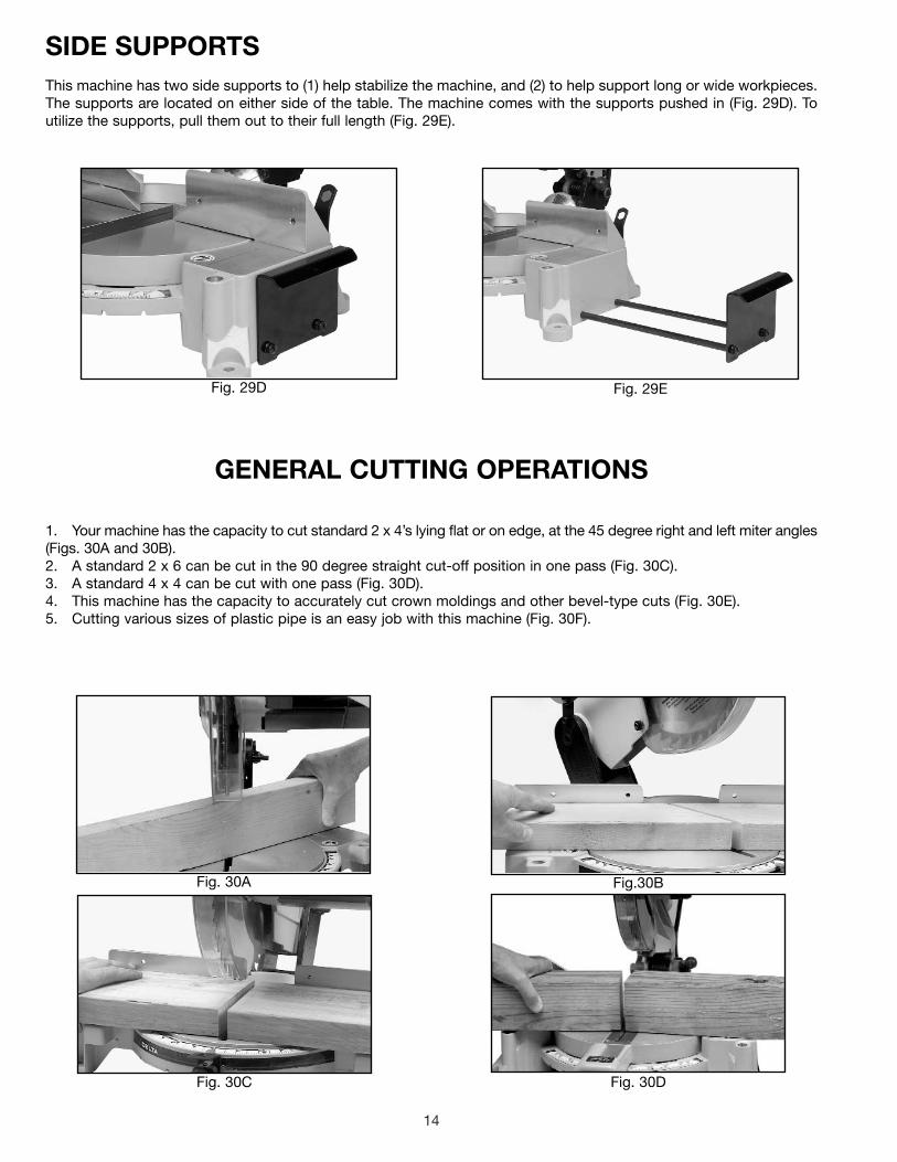
1. Your machine has the capacity to cut standard 2 x 4’s lying flat or on edge, at the 45 degree right and left miter angles(Figs. 30A and 30B).2. A standard 2 x 6 can be cut in the 90 degree straight cut-off position in one pass (Fig. 30C).3. A standard 4 x 4 can be cut with one pass (Fig. 30D).4. This machine has the capacity to accurately cut crown moldings and other bevel-type cuts (Fig. 30E).5. Cutting various sizes of plastic pipe is an easy job with this machine (Fig. 30F).
GENERAL CUTTING OPERATIONS
SIDE SUPPORTSThis machine has two side supports to (1) help stabilize the machine, and (2) to help support long or wide workpieces.The supports are located on either side of the table. The machine comes with the supports pushed in (Fig. 29D). Toutilize the supports, pull them out to their full length (Fig. 29E).
Fig. 29D Fig. 29E

15
Fig. 31
Fig. 32
CUTTING ALUMINUMAluminum extrusions such as used for making aluminumscreens and storm windows can easily be cut withyour compound miter saw. When cutting aluminumextrusions, or other sections that can be cut with a sawblade and are within the capacity of the machine,position the material so the blade is cutting through thesmallest cross-section (Fig. 31). The wrong way to cutaluminum angles is illustrated in Fig. 32. Be sure to applya stick wax to the blade before cutting aluminum stock.This stick wax is available at most industrial mill supplyhouses. The wax provides proper lubrication and keepschips from adhering to the blade.
WARNING: NEVER APPLY LUBRICANT TO THEBLADE WHILE THE MACHINE IS RUNNING.
FENCE BLADE
WRONG
FENCEBLADE
RIGHT
CUTTING BOWED MATERIALWhen cutting flat pieces, first check to see if the material is bowed. If it is, make sure the materialis positioned on the table as shown in Fig. 33.
If the material is positioned the wrong way (Fig. 34), the workpiece will pinch the blade near thecompletion of the cut.
Fig. 30FFig. 30E
Fig. 33 Fig. 34

16
Fig. 35
Fig. 36
Fig. 37
Fig. 38
CUTTINGCROWN MOULDINGOne of the many features of your saw is the ease ofcutting crown moulding.The following is an example ofcutting both inside and outside corners on 52/38 degreewall angle crown moulding. NOTE: When cutting 45 degreewall angle crown moulding, the following procedure forinside and outside corners is the same with theexception that the bevel position will always be at 30degrees and the miter position will be 35.25 degrees tothe right or left.
1. Move the table to the 31.62 degree right miterposition and lock the table in position. NOTE: A triangleindicator and positive stop are are provided on the miterscale to help find this angle quickly.
2. Tilt the saw blade to the 33.85 degree left bevelposition and tighten bevel lock handle. NOTE: A triangleindicator is provided on the bevel scale to find this anglequickly.
3. Place the crown moulding on the table with theCEILING EDGE (AA) Fig. 35 of the moulding against thefence, and make the cut (Fig. 35). NOTE: The piece ofcrown moulding used for the outside corner will alwaysbe on the right hand side of the blade (A) Fig. 35. Thepiece of crown moulding used for the inside corner willalways be on the left hand side of the blade (B) Fig. 35.
4. To make the matching halves of the inside andoutside corners, rotate the table to the 31.62 degree leftmiter position and tighten table lock handle. NOTE: Atriangle indicator and a positive stop are provided on themiter scale to find this angle quickly.
5. Place the crown moulding on the table with theWALL EDGE (BB) Fig. 36 of the crown moulding againstthe fence and make the cut. Again, the piece of crownmoulding used for the outside corner will always be onthe right side of the blade (C) Fig. 36. The piece of crownmoulding used for the inside corner will always be on theleft side of the blade (D) Fig. 36.
6. Fig. 37 illustrates the two outside corner pieces - (A)being the piece cut at (A) Fig. 35, and (C) being the piececut at (C) Fig. 36.
7. Fig. 38 illustrates the two inside corner pieces - (B)being the piece cut at (B) Fig. 35, and (D) being the piececut at (D) Fig. 36.
CD
AB
C A
D
B
AA
BB

17
Fig. 41
Fig. 42
MAINTENANCECHANGING THE BLADE
WARNING: USE ONLY CROSS-CUTTING SAWBLADES. WHEN USING CARBIDE TIPPED BLADES,DO NOT USE BLADES WITH DEEP GULLETS AS THEYCAN DEFLECT AND CONTACT THE GUARD. USE ONLY10″″ DIAMETER SAW BLADES WHICH ARE RATED FOR5200 RPM OR HIGHER AND HAVE 5/8″″ DIAMETERARBOR HOLES.
1. DISCONNECT MACHINE FROM POWER SOURCE.
2. Remove screw (A) Fig. 39 and rotate cover (B) to therear (Fig. 40).
3. To remove the saw blade, insert hex wrench (C)Fig. 41 into the hex hole located on the rear end of themotor shaft to keep the shaft from turning.
4. Use a wrench (D) Fig. 42 to loosen arbor screw (E)by turning it clockwise.
5. Remove arbor screw (E) Fig. 42, outside bladeflange (F), and saw blade (G) from saw arbor.
6. Attach new saw blade MAKING CERTAIN TEETHOF SAW BLADE ARE POINTING DOWN AT THEFRONT. Attach outside blade flange (F) Fig. 42, andarbor screw (E) by turning it counterclockwise usingwrench (D) Fig. 42. At the same time, use hex wrench (C)Fig. 41 to keep the arbor from turning.
7. Replace screw and cover that was rotated to therear in STEP 2.
WARNING: REMOVE WRENCHES (C) FIG. 41 AND(D) FIG. 42 BEFORE STARTING MACHINE.
C
Fig. 39
Fig. 40
B
A
B
F
E
D
G

18
Fig. 43
Fig. 44
Fig. 45
BRUSH INSPECTIONAND REPLACEMENTBrush life varies. It depends on the load on the motor.Check the brushes after the first 50 hours of use for anew machine or after a new set of brushes has beeninstalled. After the first check, examine them after about10 hours of use until such time that replacement isnecessary. To inspect the brushes, proceed as follows:
1. D I S C O N N E C T M A C H I N E F R O M P O W E RSOURCE.
2. Remove three screws (A) Fig. 43 and remove motorcover (B).
4. Fig. 45 illustrates one of the brushes (E) removedfrom the holder (C). When the carbon on either brush (E)is worn to 3/16″ in length or if either spring (F) or shuntwire is burned or damaged in any way, replace bothbrushes. If the brushes are found to be serviceable afterremoving, reinstall them in the same position.
3. The brushes are located in the two holders (C) Fig. 44.Remove spade type terminal connector (D) and pull outbrush holders (C).
C
D
CE
F
A
B
A

19
NOTES

The following are trademarks of PORTER-CABLE·DELTA (Las siguientes son marcas registradas de PORTER-CABLE S.A.): BAMMER®,INNOVATION THAT WORKS®, JETSTREAM®, LASERLOC®, OMNIJIG®, POCKET CUTTER®, PORTA-BAND®, PORTA-PLANE®, PORTER-CABLE®, QUICKSAND®, SANDTRAP®, SAW BOSS®, SPEED-BLOC®, SPEEDMATIC®, SPEEDTRONIC®, STAIR-EASE®, THE PROFESSIONALEDGE®, THE PROFESSIONAL SELECT®, TIGER CUB®, TIGER SAW®, TORQBUSTER®, WHISPER SERIES®, DURATRONIC™, FLEX™,FRAME SAW™, MICRO-SET™, MORTEN™, NETWORK™, RIPTIDE™, TRU-MATCH™, WOODWORKER’S CHOICE™, THE AMERICANWOOD SHOP™ (design) , AUTO-SET™, B.O.S.S.™, BUILDER’S SAW™, CONTRACTOR’S SAW™, DELTA™, DELTACRAFT™,HOMECRAFT™, JET-LOCK™, KICKSTAND™, THE LUMBER COMPANY™ (design). MICRO-SET™, Q3™, QUICKSET II™, QUICKSETPLUS™, SAFEGUARD II™, SANDING CENTER™, SIDEKICK™, UNIFENCE™, UNIGUARD™, UNIRIP™, UNISAW™, VERSA-FEEDER™ ,THIN-LINE™, TPS™, Emc²™.
Trademarks noted with ™ and ® are registered in the United States Patent and Trademark Office and may also be registered in othercountries. Las Marcas Registradas con el signo de ™ y ® son registradas por la Oficina de Registros y Patentes de los Estados Unidos ytambién pueden estar registradas en otros países.
PORTER-CABLE • DELTA SERVICE CENTERS(CENTROS DE SERVICIO DE PORTER-CABLE • DELTA)
Parts and Repair Service for Porter-Cable • Delta Machinery are Available at These Locations(Obtenga Refaccion de Partes o Servicio para su Herramienta en los Siguientes Centros de Porter-Cable • Delta)
Authorized Service Stations are located in many large cities. Telephone 800-438-2486 or 731-541-6042 for assistance locating one.Parts and accessories for Porter-Cable ·Delta products should be obtained by contacting any Porter-Cable·Delta Distributor, AuthorizedService Center, or Porter-Cable·Delta Factory Service Center. If you do not have access to any of these, call 800-223-7278 and you willbe directed to the nearest Porter-Cable·Delta Factory Service Center. Las Estaciones de Servicio Autorizadas están ubicadas en muchasgrandes ciudades. Llame al 800-438-2486 ó al 731-541-6042 para obtener asistencia a fin de localizar una. Las piezas y los accesoriospara los productos Porter-Cable·Delta deben obtenerse poniéndose en contacto con cualquier distribuidor Porter-Cable·Delta, Centrode Servicio Autorizado o Centro de Servicio de Fábrica Porter-Cable·Delta. Si no tiene acceso a ninguna de estas opciones, llame al800-223-7278 y le dirigirán al Centro de Servicio de Fábrica Porter-Cable·Delta más cercano.
ARIZONATempe 85282 (Phoenix)2400 West Southern AvenueSuite 105Phone: (602) 437-1200Fax: (602) 437-2200
CALIFORNIAOntario 91761 (Los Angeles)3949A East Guasti RoadPhone: (909) 390-5555Fax: (909) 390-5554San Leandro 94577 (Oakland)3039 Teagarden StreetPhone: (510) 357-9762Fax: (510) 357-7939
COLORADOArvada 80003 (Denver)8175 Sheridan Blvd., Unit SPhone: (303) 487-1809Fax: (303) 487-1868
FLORIDADavie 33314 (Miami)4343 South State Rd. 7 (441)Unit #107Phone: (954) 321-6635Fax: (954) 321-6638
Tampa 33609 4538 W. Kennedy BoulevardPhone: (813) 877-9585Fax: (813) 289-7948
GEORGIAForest Park 30297 (Atlanta)5442 Frontage Road,Suite 112Phone: (404) 608-0006Fax: (404) 608-1123
ILLINOISAddison 60101 (Chicago)400 South Rohlwing Rd.Phone: (630) 424-8805Fax: (630) 424-8895
Woodridge 60517 (Chicago)2033 West 75th StreetPhone: (630) 910-9200Fax: (630) 910-0360
MARYLANDElkridge 21075 (Baltimore)7397-102 Washington Blvd.Phone: (410) 799-9394Fax: (410) 799-9398
MASSACHUSETTSBraintree 02185 (Boston)719 Granite StreetPhone: (781) 848-9810Fax: (781) 848-6759Franklin 02038 (Boston)Franklin Industrial Park101E Constitution Blvd.Phone: (508) 520-8802Fax: (508) 528-8089
MICHIGANMadison Heights 48071 (Detroit)30475 Stephenson HighwayPhone: (248) 597-5000Fax: (248) 597-5004
MINNESOTAMinneapolis 554295522 Lakeland Avenue NorthPhone: (763) 561-9080Fax: (763) 561-0653
MISSOURINorth Kansas City 641161141 Swift AvenueP.O. Box 12393Phone: (816) 221-2070Fax: (816) 221-2897
St. Louis 631197574 Watson RoadPhone: (314) 968-8950Fax: (314) 968-2790
NEW YORKFlushing 11365-1595 (N.Y.C.)175-25 Horace Harding Expwy.Phone: (718) 225-2040Fax: (718) 423-9619
NORTH CAROLINACharlotte 282709129 Monroe Road, Suite 115Phone: (704) 841-1176Fax: (704) 708-4625
OHIOColumbus 432144560 Indianola AvenuePhone: (614) 263-0929Fax: (614) 263-1238
Cleveland 441258001 Sweet Valley DriveUnit #19Phone: (216) 447-9030Fax: (216) 447-3097
OREGONPortland 972304916 NE 122 nd Ave.Phone: (503) 252-0107Fax: (503) 252-2123
PENNSYLVANIAWillow Grove 19090520 North York RoadPhone: (215) 658-1430Fax: (215) 658-1433
TEXASCarrollton 75006 (Dallas)1300 Interstate 35 N, Suite 112Phone: (972) 446-2996Fax: (972) 446-8157
Houston 77055West 10 Business Center1008 Wirt Road, Suite 120Phone: (713) 682-0334Fax: (713) 682-4867
WASHINGTONAuburn 98001(Seattle)3320 West Valley HWY, NorthBuilding D, Suite 111Phone: (253) 333-8353Fax: (253) 333-9613
Printed in U.S.A.
CANADIAN PORTER-CABLE • DELTA SERVICE CENTERSALBERTABay 6, 2520-23rd St. N.E.Calgary, AlbertaT2E 8L2Phone: (403) 735-6166Fax: (403) 735-6144
BRITISH COLUMBIA8520 Baxter PlaceBurnaby, B.C.V5A 4T8Phone: (604) 420-0102Fax: (604) 420-3522
MANITOBA1699 Dublin AvenueWinnipeg, ManitobaR3H 0H2Phone: (204) 633-9259Fax: (204) 632-1976
ONTARIO505 Southgate DriveGuelph, OntarioN1H 6M7Phone: (519) 836-2840Fax: (519) 767-4131
QUÉBEC1515 ave.St-Jean Baptiste,Québec, QuébecG2E 5E2Phone: (418) 877-7112Fax: (418) 877-7123
1447, BeginSt-Laurent, (Montréal),QuébecH4R 1V8Phone: (514) 336-8772Fax: (514) 336-3505