1 xaca rma50k27 - digital library/67531/metadc58776/m2/1/high...lift-curve slopes of all six kings...
TRANSCRIPT

1 .
-- 4% CL . c XACA RMA50K27
NATIORALADVIS&YSOMMITPEEFCRAEROKAUI'ICS
BFSEARCE -uM
!mFzEFFECTSc@MAcE~m~m~om~
AERCDYNAMICCBARACIERISTICS~SKVERAB~~CK
WINSRAVIEIG 35°CE'SWEEpBACKAED
vAR1OTJSAMOmm c@w
By Bruce E. Tfnling and W. Rfchard Kour
A comparison of the lift,'drag, and pit mm3nt characteristics of several wings having 35O of sweepback and various -sofc~r . has been made from the results of wind-tunnel tests. Six semispan model wings were tested: three having &9 aspect ratio of 10, and three having an aspect ratio.of 5. The stream&se sections for the three wings of each aspect ratio were the NACA 65lACl2, the NACA 641A312, and the mx 641~612. The Reynolds mu&er was varied from 2,OCO,OOO to 1O,OW,ooO at a &ch number of 0.25, and the Hach nmiber was varied from 0.25 to 0.92 at a Reynolds number of 2,000,OOO.
The effects of Reynolds nmiber on the l-peed aerodymmic chsrac- teristics were large and were believed to be associated with a reduction of lift on the outer portions of the wing as the Reynolds nuuiber was reduced. At low lift coefficients, the effects of increasing the Mach number, up to the Mach Puaiber for drag dfvergence, were to increase the lift-curve slopes of all six Kings and to &crease the static longitudi- nal stablljtty of the wings having an aspect ratio of 10. The static longitudinal stability of the whys having an asmct ratio of 5 remained nearly constantwithinthe same range of Machmmibers. As the Machnum- ber for drag divergence was exceeded, the lfftcurve elope decreased and a large reduction in static longjltudinal stability occurred.
The effects of camber on'-& m lift coefficient, the a&e of
. attack for zero lift, and the pitcwmnt coefficient for zero lfft were as would be anticipated from the section aerodynamic characteris- tfCB. Low-peed results at a Reynolds nmiber of 10,000,ooO indicated * . that caviber increased the.lift-drag ratio of the wings having an

2 * c--
NACARMA%X27
aspect ratio of 10, but no similar increase was noted for the wings having an aspect ratio of 5.
At high subsonic speeds and a Reynolds number of 2,000,000, caniber, in general, reduced the Mach number for drag divergence. At Mach numbers less than that'for drag divergence , camber caused considerable improve- ment fn the lift+irag ratio and the pitching+mrmnt characteristics. On the basis of the effects of Reynolds number Indicated by the low-speed data, there is doubt that these improvements due to camber would be entirely realized at Reynolds nmibers greater than 2,ooO,OOO.
The effectiveness of Wang sweep in deLaslng the detrimental effects of compressibility to higher Mach nmibers U-well known. one of the principal difficulties encountered in the use of swept+ack wings of high aspect ratio is the low lift coefficient at which large changes of static longitudinal stability occur. Since this effect is attributed to stallfng of the outer portions ofthewing, ftfoI.lowsthat increase in the lif%.coefficient at which large changes -of statk longitudinal sta-
bility occur tight be realized by increasing the msximum lift coefficient of the wing sections. The use of c&er is a familier mans of increas- ing the maximum lift. coefficient as well aa the Uft-drag ratio of unswept wings, Research on the effects of ca&er snd ttist on the aerr+ dynamic characteristics of swepthack wings has been reported In ref- erences 1 and 2. The present investigation was initiated to evaluate the effects of cazdber alone and also the effects of mc scale and compressibility on the aerodynamic characteristics of several win@;6 having 35' of aweepback.
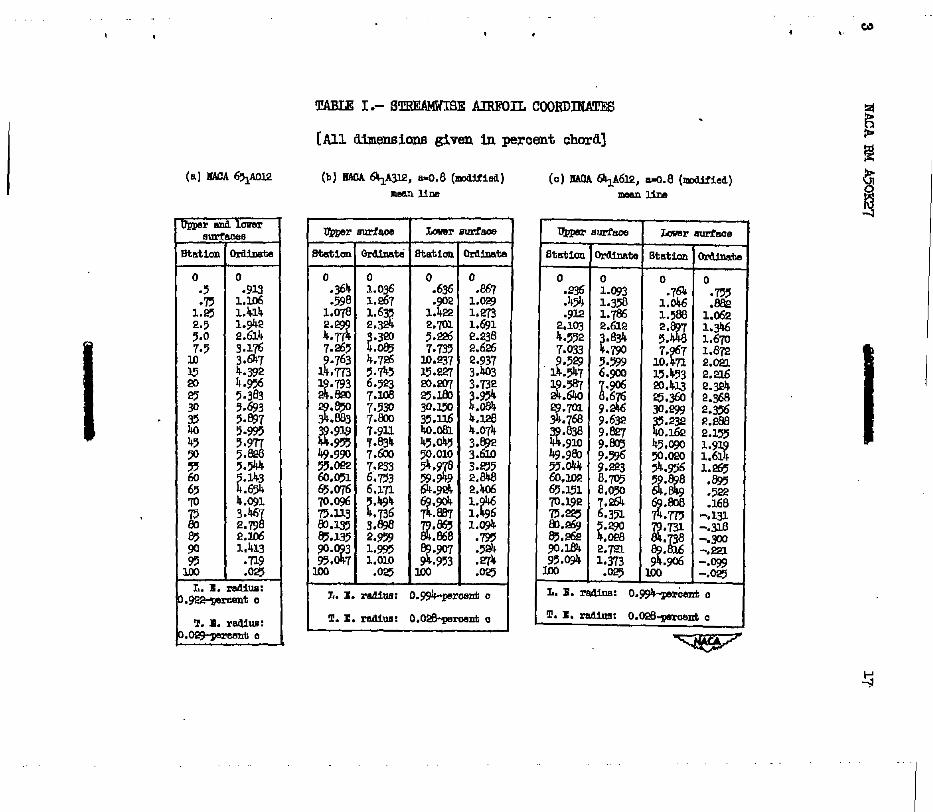
Six semispsn model wings were. tested: Three representing wings hav- ing an aspect ratio of 10, and three representing wings having an aspect ratio of 5. The streanrwise sections of the three wings of each aspect ratio were, the XACA 6ylA012, the HASA 64111312, and the NAcA 641~612. According to simple sweep theory, the aerodynamic characteristics of SeCtiOnS perpendicular to the quarter-chord lfns determine the aerody- namic characteristics of a swept-back wing. The sections perpendicular to the quarter-chord khe of the wings investigated were approximtely 14 percent thick and had desigu.lift coefficients of about 0, 0.37, sad 0.73. Results of tests of airfoil sections reported in reference 3 have indicated that the addition of camber increases the msximum lift coef- ficient for airfoil sections having thickness-chord ratios of less than 12 percent, but that the effectiveness of camber in increasing the maxi- mun lift coefficient d-imin-ishes as the thiclmess is ticreased beyond 12 or 15 percent. For the 14-percenGthick wings tested in the present

RACA RM A50E7 3
investigation, the increase in the maximum lift coefficiefit resulting from camber and hence the increase in the lift coefficient at which longitudinal instability occurs should be significant but map not be expected to be as great as that which would be anticipated for thinner WfngB .
The tests were conducted over a range of Mach numbers from 0.25 to 0.92 at a Reynolds nu&er of 2,000,OCO and over a range of Reynolds num- hers from 2,000,OCQ to 10,000,OOC at a Mach number of 0.25. .
cr, %
%
A
M
R
S
v
L/D .
drag coefficient (3)
3nidm.m profile4xag Coefficient ass- elliptical span load
distribution, minTmum ci;' valueof CD-x .
lift coefffcient lift
( ) yr pitchivnt coefficient about axis passin@; through the gusr-
ter point of the -an a.erodynamTc chord pitching moment qs a >
pitch-ment coeffkient at zero lift
aspect ratio
Mach number s 0
Reynolds nunker
semia= WWs =ea, square feet
airspeed, feet per second
lift-drag ratio lift ( > iirag
i -

4 lWCA RM A50E27
a
b
speed of sound, feet per second
span of complete wing masured perpendicular to the plane of symmetry, feet
C chord, measured psrallel to the plane of s-try, feet
a meanaerodynamk chord , feet
q
Y
a
aO
P
l-c
dynamLc pressure, pounds per square foot
lateral distance from plane of symmtry, feet
angle of attack, degrees
angle of attack for zero lift, d.egrees
density of air, BlUgB per Cl&k foot
absolute viscosity, slugs per foot second
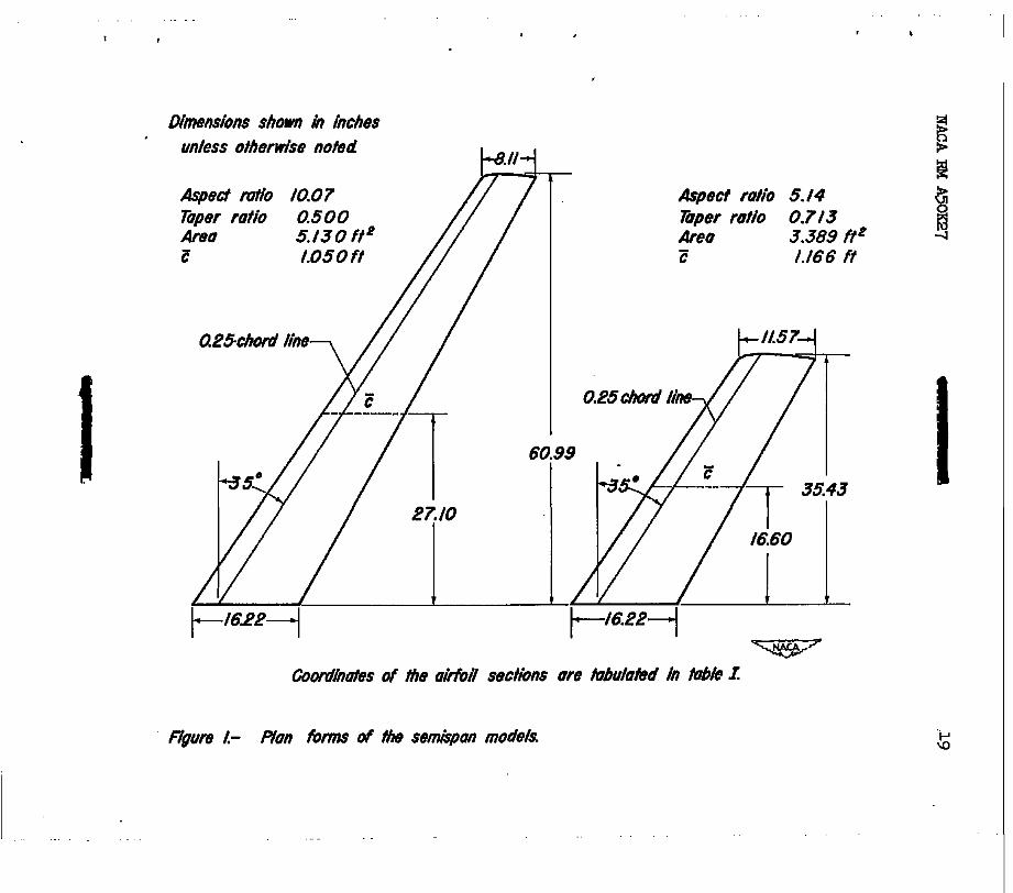
The six semispan models teated in this investigation were furnished by the Lockheed AircreSt Corporation. Three of the models represented wings having an aspect ratio of 10 and a taper ratio of 0.5; and the other three represented w3ngs having an mpect ratio of 5 aml a taper ratio of approximately 0.7. Eachmodel had 39 of sweepback of the quarter-chord line. The dilEinSiOIlB oft+ model8 83% BhCfW?l in fi@l333 1.
The thiclmess distribution of the sections of each model was the sam3 from root to tip and there was no twist. The wing sections in p-8 parallel to the plane of Bymetry were the RAGA 65lAO12, the NACA 64lA312, muI the RACA 641A6l2. The wings with these BeCtioIlB Will
be referred to ti this report as the uncanibered, moderately canibered, and hQhlyca~&eredwinga, respectively. The meanline of the camberedair- foil sections was the IW!A ~0.8 (modified). (See reference 4.) Accorb- &YJ to simple sweep theory, the aerodynamic characteristics of the wing sections perpendiculartothe quwter-chordline determine the aerody- namic characteristics of a swept+ack wing. The sectfons perpenditi to the quarter-chord line of the model w’ings were abowt 14 percent thick
.
* . /-
NACA RMA5OlE7 5
and had design lift coefficients-of about 0, 0.37, and 0.73 for the uncanibered> moderately cmibered, and highly cambered wings, respectively. 5e COOrdImteB of the stresmwise sections are tabulated ti table I.
The tip of each win@; was fozmed by a haIf' body ham a radius equal to the corresponding half thfclmess of the wing section.
The models were constructed of steel. 5 0uterpoAions of the model wings having an aspect ratio of 10 w&e removed and replaced tith tip fair-8 to form the wings having &p aspect ratio of 5.
5e horizontal turntable upon which the models were mounted in the wind tunnel is directly connected to the bal&ce system. 5e models were mounted with the root chord in the plane of theturntable as shown in figure 2. 5e $.moture betweenthe models andtheturntable was sealed.
.
Two series of tests were conducted: one to evaluate the effects of Reynolds nmiber at a low Mach nux&er, and one to evaluate the effects of compressibility at a constant Reynolds number. 5 tests to evaluate the effects of Reynolds nuniber were conducted at Reynolds mmibers from 2,000,ooO to 10,000,000 at a &ch pzmiber of 0.25. !I!he tests to evaluate the effects of compressibility were conducted at Mach n&ers from 0.25 to 0.92 at a Reynolds n&her of 2,000,OOO. Lift, drag, and pitching molosnt were Iosasured over a range of angle of attack sufficient to obtain lift coefficients from less than zero to that for the stall' exceptwherethe rangewm limitedbywind-tunnelpower orbythe capac- ity of the fcWce balsnce.
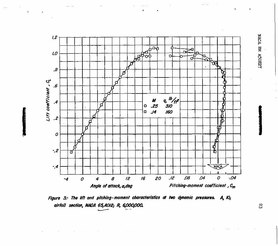
5 dynamic pressure of the tests varied from approximately 96 to 360 pounds per square foot between the Mach nm&ers of 0.25 and 0.92 at aReynoldsnuniberof2,000,000,anaframapprox~~lg~to500pounds per square foot between the Reynolds mmibers of 2,000,ooO and 10,000,000 at a &ch nuzliber of 0.25. Because of this variatfon of dynamic pressure, a test was conducted to evaluate the effects of distortion of the model wings under load. ThTs w-as accomplished by obtaining data at a Reynolds number of ~,OOO,OOO at dynamic pressures of 160 and 310 pomds pe$ square foot which correspond, under the test candltions, to Mach nmibers of 0.14 and 0.25, respectfvely.

6 -.
C!CXKRECTIORSTOIWCA
NACA RM A50K27
5 data have been corrected.for the effects of tumel-mll inter- ference, including constriction due to the tunnel walls, and approxi- mately for model-support tare forces.
Correctfons to the data for the effects of turmel+mJl titerference originating from lift on the model have been evaluated by the method of reference 5 using the theoretic&L span loading for incompressible flow calculated by the method of reference 6. 5 corrections added to the dreg and to the angle of attack were:
For model wings having an aspect ratio of 10:
&= 0.295%
&)= 0 .OOkj’2 CL2
For mod.elwings havSng an aspect ratio of 5:
hr = 0.263 c,
Constriction effects due to the presence of the tunnel walls were coxqmted by the m&hod of reference. 7. 5se corrections have not been modified to allow for the effect of sweep. Thel.tqqlitudeofthecmc+ tions to the Mach mmiber and to the dymmic pressure is shown in the following table:
Comebed Machnmiber
r .
&corrected Q corrected Mach Rmiber --1 q uncorrected
A=101 A=!5 t A=10
0.699 0.700 -749 .749
:Tg :E .848 2349 .872 .873 .&a .@7 -913 -915
'1.002 1.002
~1.003 Il.003 1.003 1.004
'1.005 1.007
A=!5 1.001
1.001
1.002
I 1,002 1.002 1.003 1.004 1.005
,
.
I
E4CA RMA5OE7 7 L
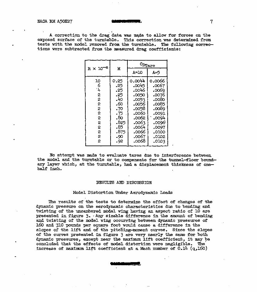
A correcti.onto the dr& data was m+de to allow for forces on the exposed surface of the turntable. This CorrectioQ was determIned from tests with the mod&removed from the turntable. The following correc- tions were subtracted frcna the measured drag coefficients:
RXl0-e M - @Tare
A=10 A+
10 0.25 0.0044 0.0066 .: .25 -25 a045 .0046 m67
a069 2 2
:E l wm .0076 -0053 ..ooeo
2 .60 .m56 .0085 2 -70 .0058 .008g 2 2
:E .0060 .Wl .0062 - .oog4
2 -825 ~1063 .oog6. 2 -85 a064 -0097 2 .875 .0066 .OlOO 2 -90 .0067 .olo2 2 .92 A068 .olo3
Iio attempt was made to evaluate tares due to Werference between the model and the turntable or to comnsate for the tmnel4'loor bound- asg layer which, at the turntable, had a displacemmt thicImess of one- half Lnch.
RESULTS AND DISCTJSSIOH
Model Distortion Under Aerodynamic Loads
The results of the tests to determine the effect of chenges of the dynmic pressure on the aerodyaamfc characteristics due to bending and t&sting of the unca&ered &de1 wing having an aspect ratio of 10 are presented ti. figure 3. -Any sizable difference in the amomxt of bending sad twisting of the model wing occurr5ng between mc pressures of 160 snd'3lOpounds per square foot would cause adifference inthe slops of the lift and of the $tcbti curves. Since the BlqPeB
of the curves presented infigure 3 are verynearlythe ssme forboth . dynamic pressures, except; near the maxlmumlift coefficient, it may be
concluded that the effects of model distortfon were negligible. The increase of mximuu Uft coefficient at a Mach nu&er of 0.14 (q,l&I)
8 NACARMA%XE!7
over that at a Mach number of 0.25 (q,jlO) is consistent with the effects of Mach nmiber on the maximum lift coefficient reported in reference 8.
EffeCtB of Reynolds Runiber
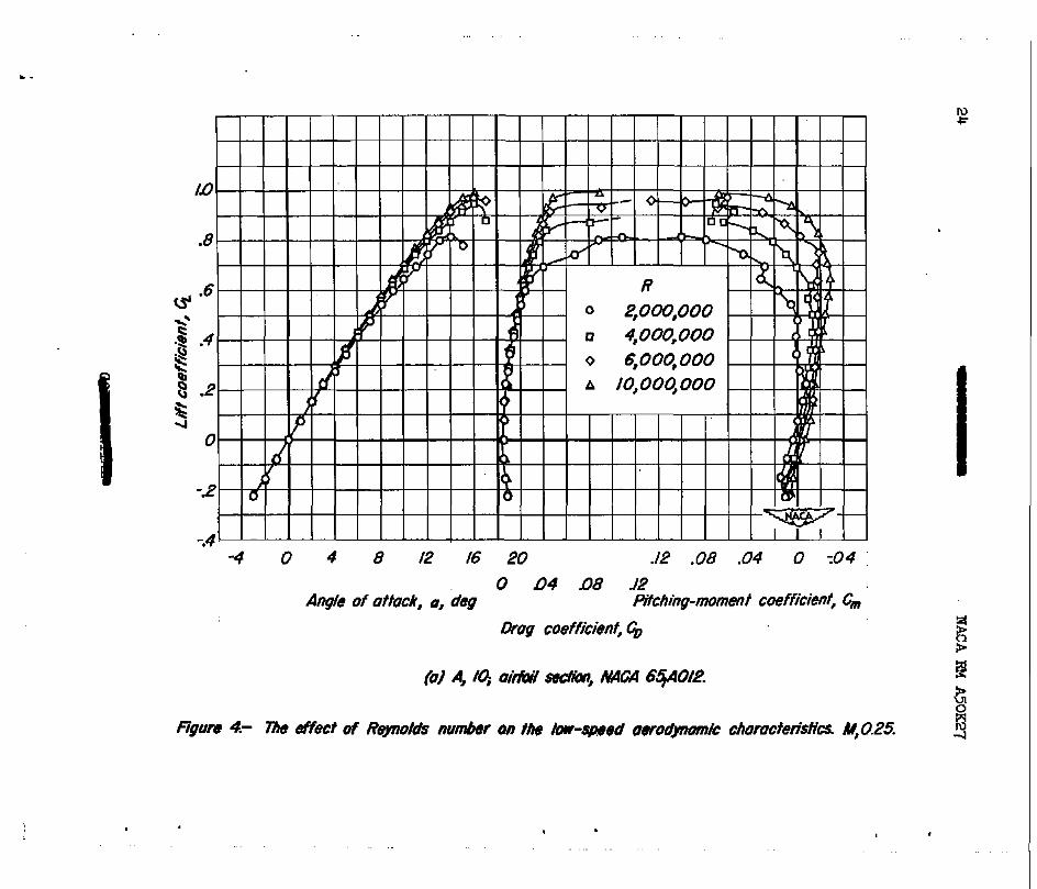
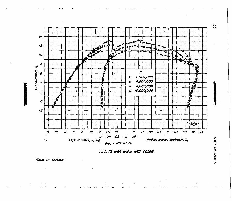
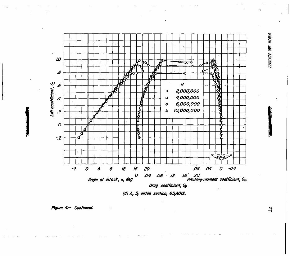
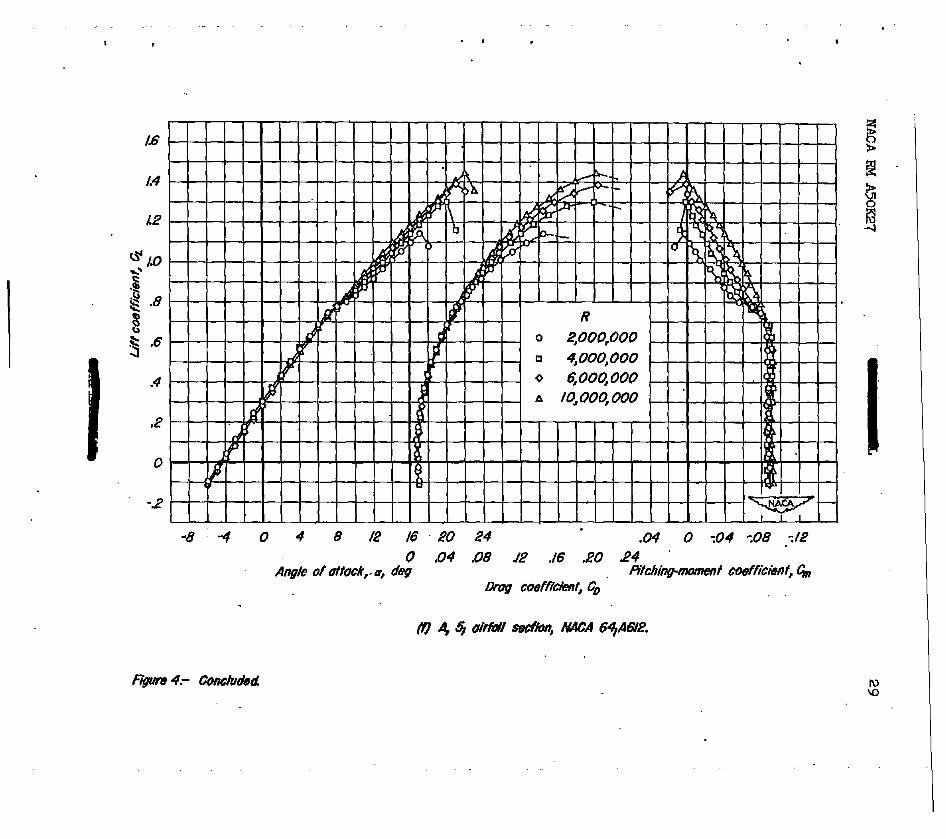
The resIik8 of tests conducted to eVab&e the effects of Reynolds number at a Mach mn&er of 0.25 are presented in figure 4. These results show that the aerodynamic characteristics in the upper lift--coefficient range were sensitive to changes in the Reynolds number. In this upper lift-coefficient range a large reduction of static longitudinal stability occurred. This reduction, which may be correlated with a decrease iu liFtcurve slope, is-believed to have been caused by a decrease of the lifticurve BhJ~36 of the outer sectionB of the wings. ~Crf3&Bing the
Reynolds number mitigated this reduction in static longitudinal stability and increased the Ilft-curve slopes of the wings at the higher lift coef- ficients. IncreasingtheReynolds nmiberalso causedalarge increase in the maxirmmlift coefficient for all six tings.
An increase in the Reynolds nuuiber resulted in a slightly less nega- tive angle of attack for zero lift for the cambered wings. In general, the effects of Reynolds nu.&er on the pitch- nt coefficient near ths design lift coefficient of each Wang (approximately equal to the streamw'ise section design lift coefficient multiplied by the cosine of 35’) were small. The chsnge in the pitching-monrsnt coefficient for iero lift tithincreasingReynolds nuniber for the uncamberedwTng whichhad an aspect ratio of ?O (fig. 4(a)) is not clearly understood. This change, however, in the pitcwment coefficient for zero lift is believed to have been caused by a difference between the effects of Reynolds number on-the chordwise extent of the lamfnsr boundaryleyer onthe upper and lower surfaces oftheting. .
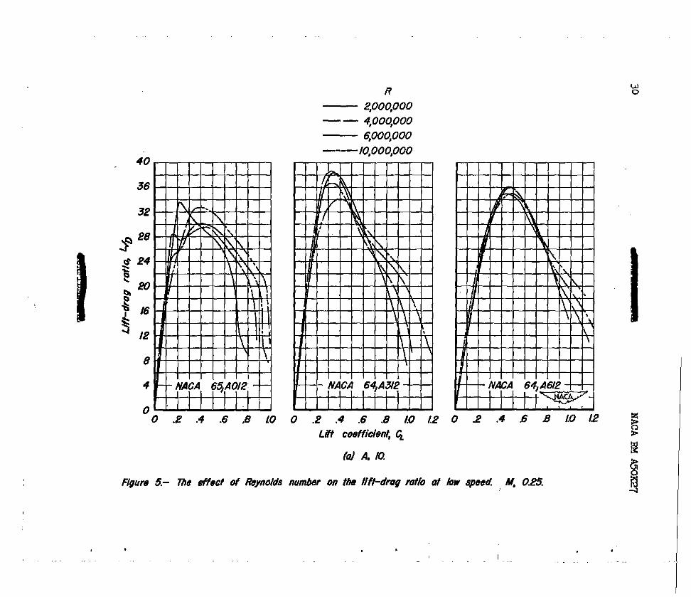
Lifb-drag ratios computed from the data of figure 4 are presented in ff@gure 5. An increase of the Reynolds number from 2,000,OOO to 10,000,000 increased the lift-drag ratio at high lift coefficients for sll six wings
and decreased the maximum lift4rag ratio of all but the aspect-ratio-10 highlyc&beredting.
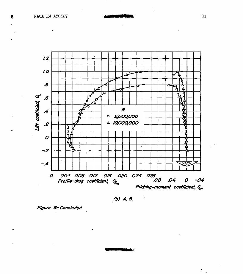
A discontinuity occurredinthelift, drag, sndpitchi~ment data for the uncambered wings at a lift coefficient of apprxtmately 0.2 at aReynolds num'oer of 2,000,OOO. (See figs. 4(a) and 4(d).) This dis- continuity is associated with termination of the 1ouMrag range of the airfoil sections rather than any three-dimensional effect. 5 varia- tions of profile-drag coefficient (assumtng elliptical span load distri- bution) and the pitchi~ment coefficient are presented as functions of lift coefficient in figure 6. From these data it may be seen that
2 NACARMAXX27 - * 9
the discontinuity in the pitching-moment data occurred at the same lift coefficient as the increase in drag corresponding to the termination of the low*ag range. Increasing the Reynolds number from 2,000,OOO to lO,OOO,OOO reduced the positive lift coefficient at which the low4rag range was termhated from approximately 0.2 to 0.1.
Effects of Mach Nuder
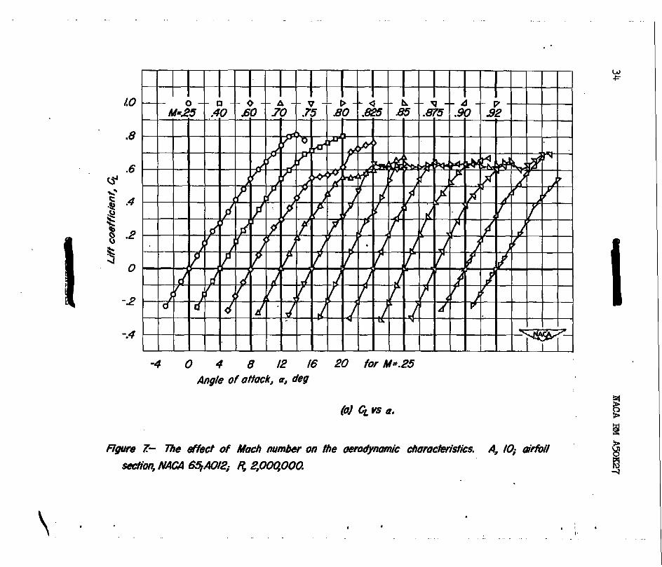
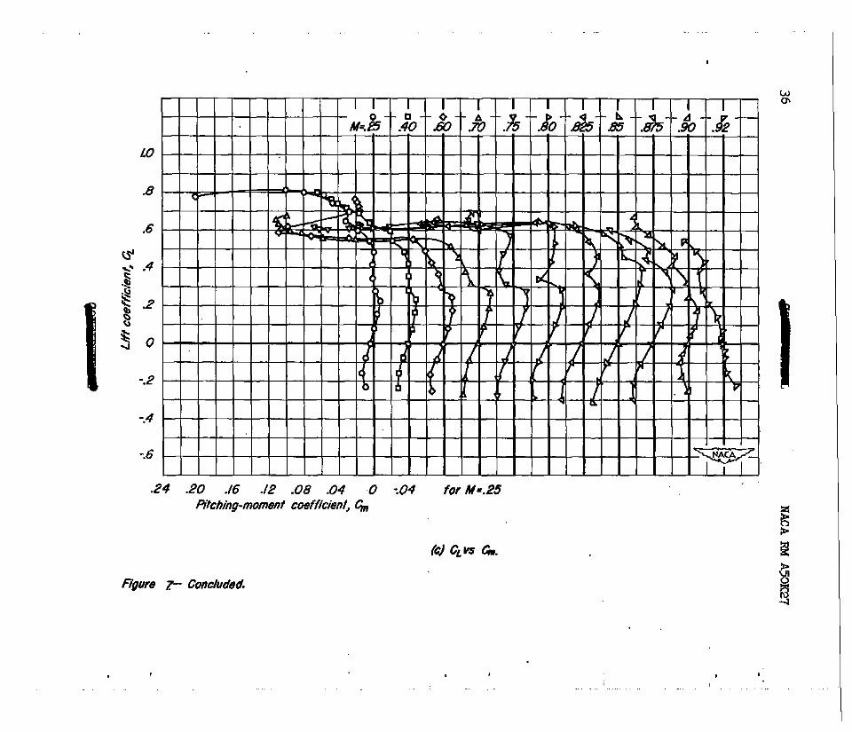
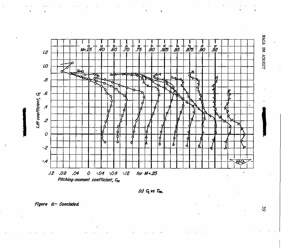
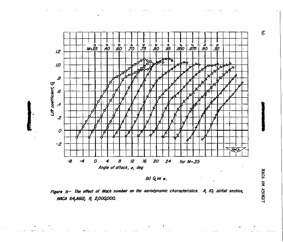
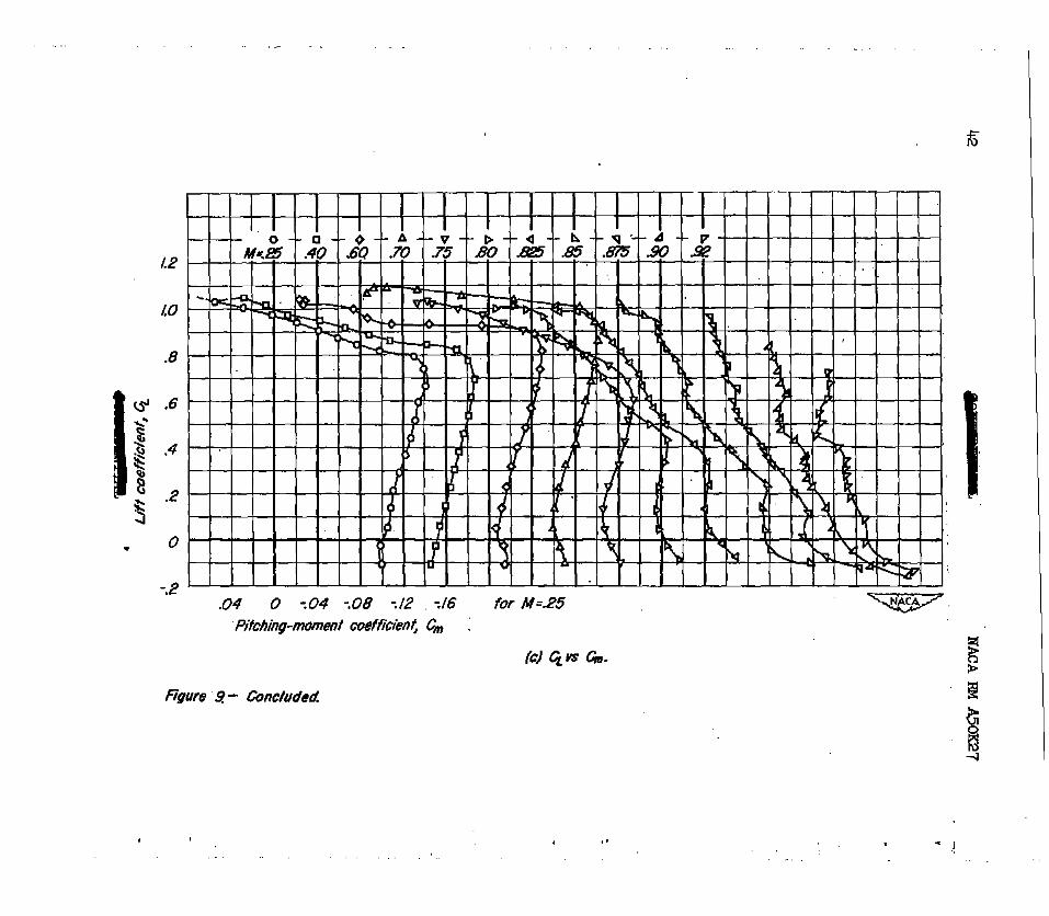
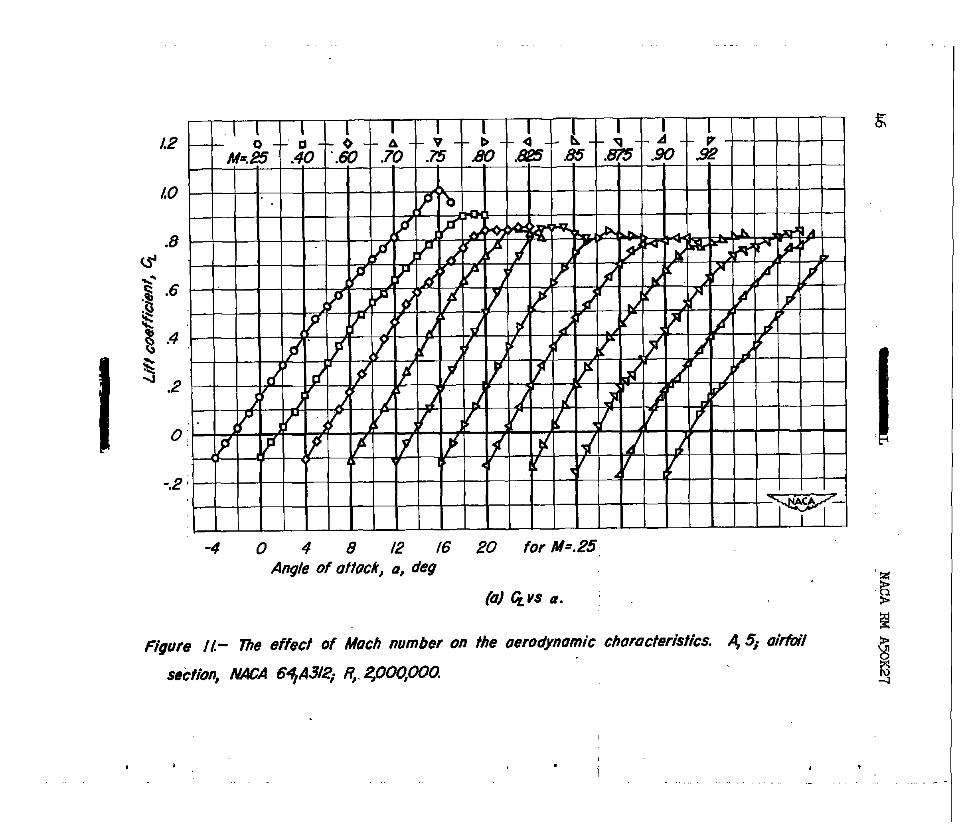
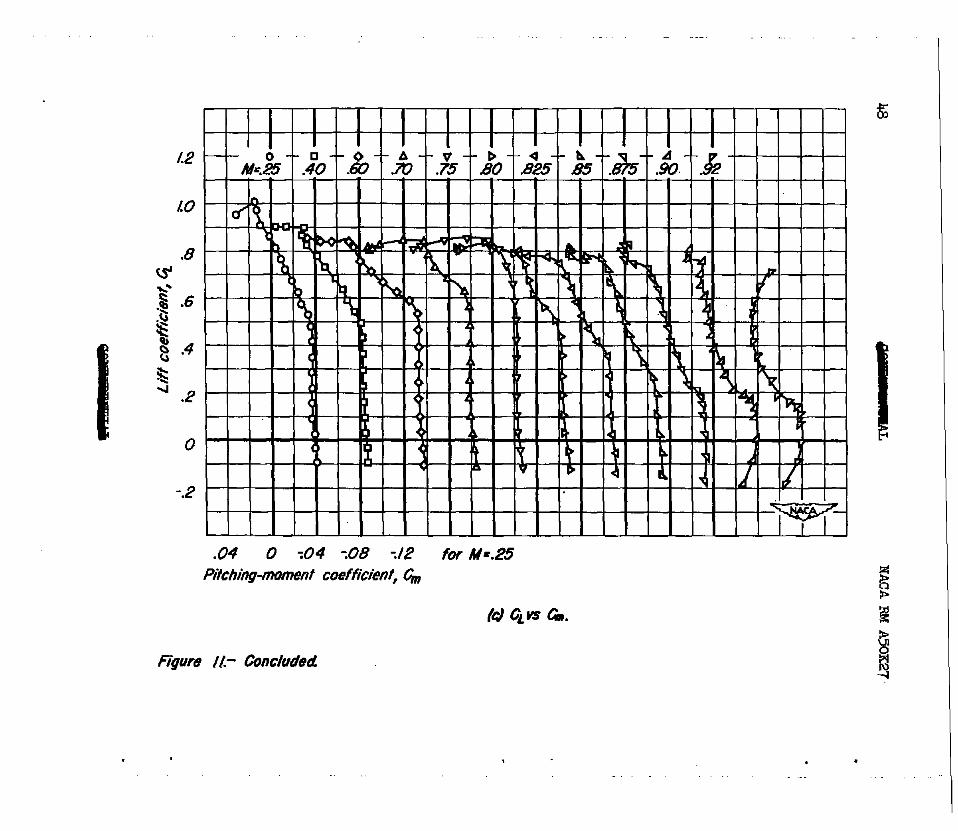
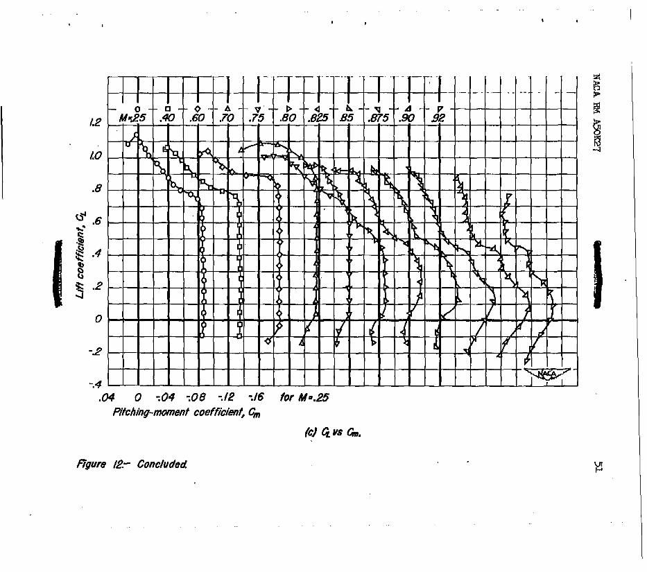
The data obtained from tests at a Reynolds nuniber of 2,ooO,OOO for a range of Mach nu&ers from 0.a to 0.92 axe presented in ffgures 7 through 12. The lift coefficient at whICh an abrunt decrease in static longitudinal stability occurred, which can be correlated with a decrease in the lift-curve slope, increased with increasing Mach n&r up to the Machnumberwhere there occurrednearly szfmultaneouslyadecrease of lift--curveslope, a decrease of st&b,j.lity, and a drag ??iSe. This Mach number will be referred to in this report as the force-dfvergence Mach nuder.
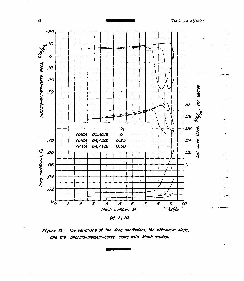
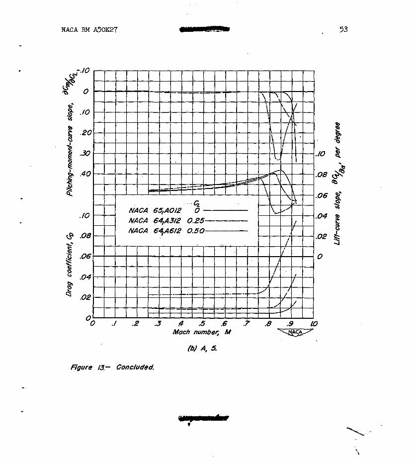
5 data in figure lj show the effect of Mach number on the pitc~msnt4urve slope aCm/&D,thelift--curve slcrpe &D/aa, and the drag coefficients for the six wings at lift COeffiCi8ntS near their respective dssign values. These data showthatthe liftcurve slope of each wing increased with Mach nusiber up to the force-divergence Mach nmiber. For this same Mach number range, the wings which had an aspect ratio of 5 were approximately neutrally stable about the quarter point of the lnsan aerodyns&c chord. 5 slopes of the pitch3ng9DD.bent ourves &m/&~ of the wings whPch hadanaspect ratio of lOwere apprax- imately-O.06 ata&chnumber ofO.25 and, ingeneral,becasle IM)re neg- ative, Wdicating increasing static longitudinal stability, as the Mach number for force-divergence was approached. For the wings of both aspect ratios, serious static longitudinal instability resulted when the Mach nu&er for force divergence was exceeded.
Effects of Camber
Discussion of the effects of camber is complicated by-the differ- ences in the thictiess distributions between the cambered and the uncant- bered wings, the streamwise thicImess distribution of the cambered wings being the NACA 641~0~ and that of the uncanrbered wings being the NACA 65lAOl2. An estimate of the probable difference in the maximum lift coefficient between sweptiack wing8 having NACA 6klAOl2 and NACA 65lAOJ.2 sections has been made through the use of simple sweep theory. According to simple sweep theory, the differences in the maxi- mum lift coefficients‘ of the sections perpendicular to the quarter-chord

10 NACA RM A5OK27
. line must be found in order to evaluate the difference in the mR*i lift coefficients of wings having different streamwise seotions. The thickness of the airfoil sections perpendicular to the quarter-chord line of the subject wings was approximately 14 percent of the chord. Rata presented in reference 3 show that at a Reynolds mmiber of ~,OOO,OOO ' (equivalent Reynolds number of about g,OOO,OOO based on the swept wing of this investigation), the section maximum lift coefficient of the uncaps+ bered 14-percent thick 64-series airfoil section is approximately 4 per- cent greater than that for the uncanibered &4-percent-thick 65-series air- foil section. This same percentage increase in the maximum lift coeffi- cient may also be expected to exist between the NACA 65A-and &A-series sectionsaocording to results presented in reference 4. The effect of variations in the section-thickness distributions on the data obtained I at high Mach numbers is believed to be small in view of the results of the investigation report& in reference 9 which Indicate that the lift- and drag-divergenoe Mach numbers for the l2-percent-thick 65-eeries and herlea airfoil sections are nearly the aame over a wide range of lift . coefficients.
It must be noted that the results of tests of airfoil sections reported in reference 3 have indicated that the addition of camber increases the maximum lift coefficient for airfoil sections having thickness-chord ratios of less than 12 percent, but that the effective- he88 of camber in increasing t$e maximum li_ft c~fficient diminishes as the thickness ratio is increased beyond 12 or 15 percent. Sihce the sections pe~ndicular to the qusrter-chord line of the wings tested in this investigation were about 14 percent thick the increase due to cant ber in the maximum lift coefficient and hence the lift coefficient at which a change In static longitudinal stability occurs would not be expected to be as great as that for thinner wings.
The lift, drag, and pitch- nt characteristics of the winp;B
' with various amounts of caliber are presented in figure 14 for a %ch number of 0.25 and a Reynolds number of lO,QOO,OOO. The values of perti- nent aerodynamic parameters taken from the data of figure 14 exe pre- sented in the following tables: . ,

ll
=At R,
Parameter
Design 0, wL/aa> design CL
"%nax aO
(%@L)design k
cm0
%%ill (Lb),, CLfor (L/b),,
1 1
'SPEYJT RATIO 10 Airfoil section
NAC!A 651+2
0 ,075
-97 0 -.071 -moo6
-0032
32.5 .38 . .
(fig. 4.)
NACA 64lA3l2
0.25 l 5
1.24
-2.2O -.0&i -A48
A060
34.0 l 40 ,
NACA 64~~61-2
0.50 .b75
1.32 JL4O
-.lOO -.OgO
AC%4
35.0 .49
ASPECT RATIO 5. I Airfoil section
Parameter w
Design CL 0 0.25 WL/w design c, .063 .064
1.00 1.32
a0 0 --2.2 .002 306
--CM ~ .0066
NACA 641~~ NACA 641A.612
0.50 .064
1.44
-4.4 -.016
22.5 -29
-.og1
-0073
a-5 -32
The principal effect8 of Woreas& caniber, as would be &icip&ted from airfoil-section aerodynamic characteristics, mre an increase in the m lift coefficient, a decrease in the angle of attack for zero lift, and an increase in the negative value of the pitchi at zero lift.
vnt coefficierct
I

I2 ’ NACARM Af3X27
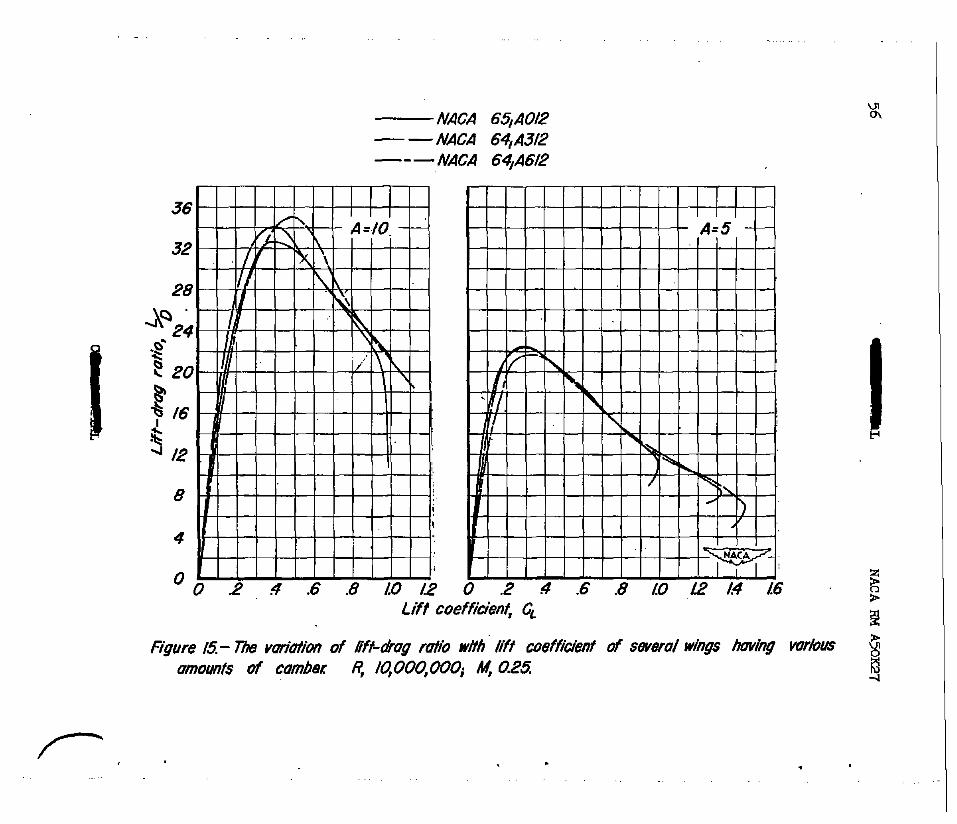
Camber improved the maxlmum 1iftcdra.g ratio of the wings which had an aspect ratio of l0, the maximum lift&rag ratio of the highly csm- bered wing being roughly 10 percent greater than that for the uncambered wing. (See fig. 15.) However, no improvement was observed in the maxi- - mum 1iftcdra.g ratio of the wings having an aspect ratio of 5. .!Che lift- drag ratio at high values of lift coefficient for the wings of both aspect ratios was improved by camber because of the higher maximum lift coefficient of the cambered wings.
Comparison of the pitching-moment data of figure 14 for the wings having an aspect ratio of 10 indicates that a moderate amount of camber lessened the changes in static longitudinal stability at lift coeffi- cients greater than 0.6. This was the only instance for which the static longitudWal.stability was improved in the upper-liftccoefficient range by camber at a Machnumber of 0.25 end a Reynolds nxmiber of 10,000,000. The Instability of the uncambered wings in the upper-liftr coefficient range was not accompanfed by a large drag rise and is therefore believed to have been due to trailing-edge separation. Furth ermore, measurements of surface static pressures on the uncambered wing of aspect ratio 5 at a Reynolds number of lO,OOO,OCO and a Mach number of 0.25 showed that initial flow separation on this wing was in the region of the trailing edge. From consideration of tw+dfinensional section characteristics, camber could be expected only to aggravate the trailing-edge separatfon. This possibly accounts for the lack of any consistent signfficant improvement due to ceziber in static longitudinal stability In the upperlift+coefficient range.
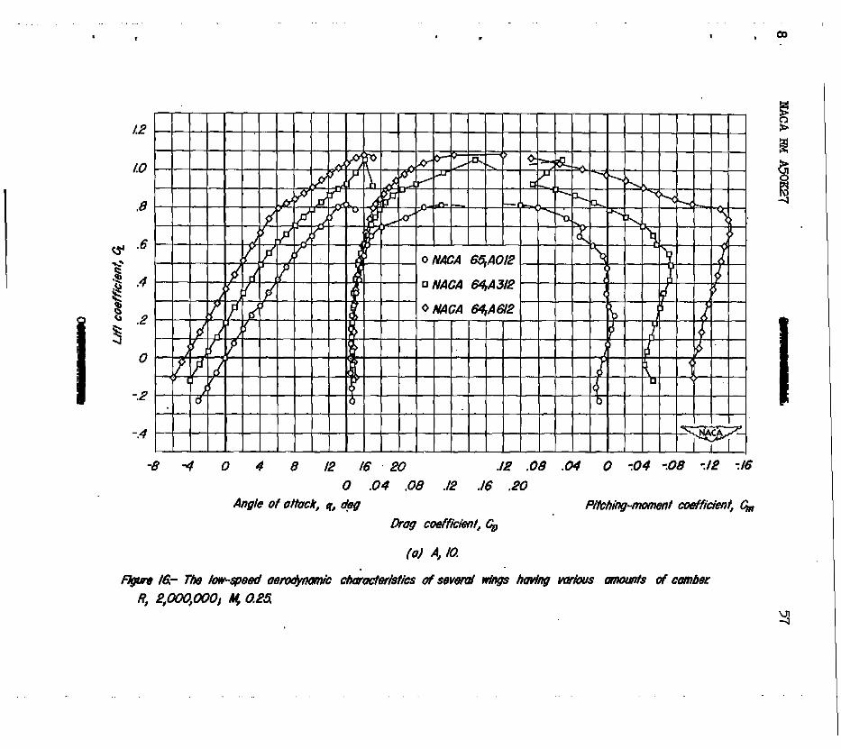
Comparison of the data for the three vfngs of each aspect ratio obtained at a Reynolds number of 2;000,000 indicates that, at'this low Reynolds number, camber caused marked improvement in the aerodynamic characteristics at high lift coefficients. Such a comparison may be made from data presented in figure 16 which were obtaFned at a Mach number of 0.25. Inspection of these data reveals that, in addition to improving the maximum lift coefficient, camber caused increases in the lift coefficient at whfch static longitudinal Fastability occurred and reduced the drag coefficient at large values of lift coefficient.
Comparison of the data of figures 7 through 12, whfch are for Mach numbers from 0.25 to 0.92 and a Reynolds number of 2,000,000, indicates that the improvements due to camber in the mqimum lift coefficfent and in the lift coefficient at which static longitudinal W&ability occurred were maintafned at Mach numbers up to the forcevergence Mach number. In addition, the lift data show that the angle of attack f& zero lift of the cambered wings became less negative as the Mach number was increased beyond 0.80.
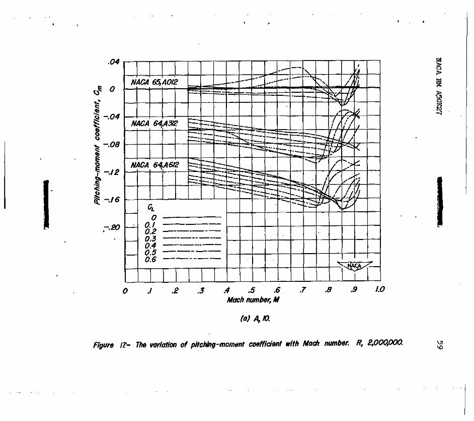
The pitcheoment coefficients for given values of lift coef- ficfent are presented'as functions of Mach number in figure 17. These
EACARMA5OK27 13
.
.
.
data show that the pitchinginament coefficknts of the cambered wings became more negative with increasing Mach number up to the force- divergence Mach,ntier where en abrupt positive increase in the pitching- moment coefficients occurred.
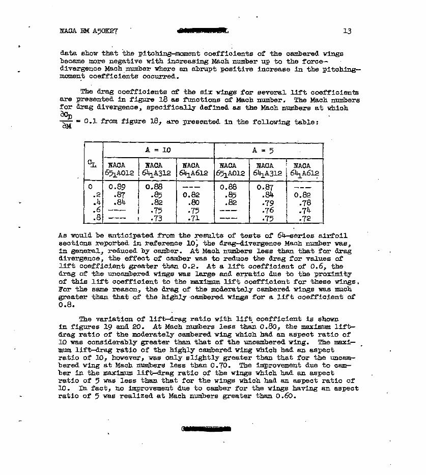
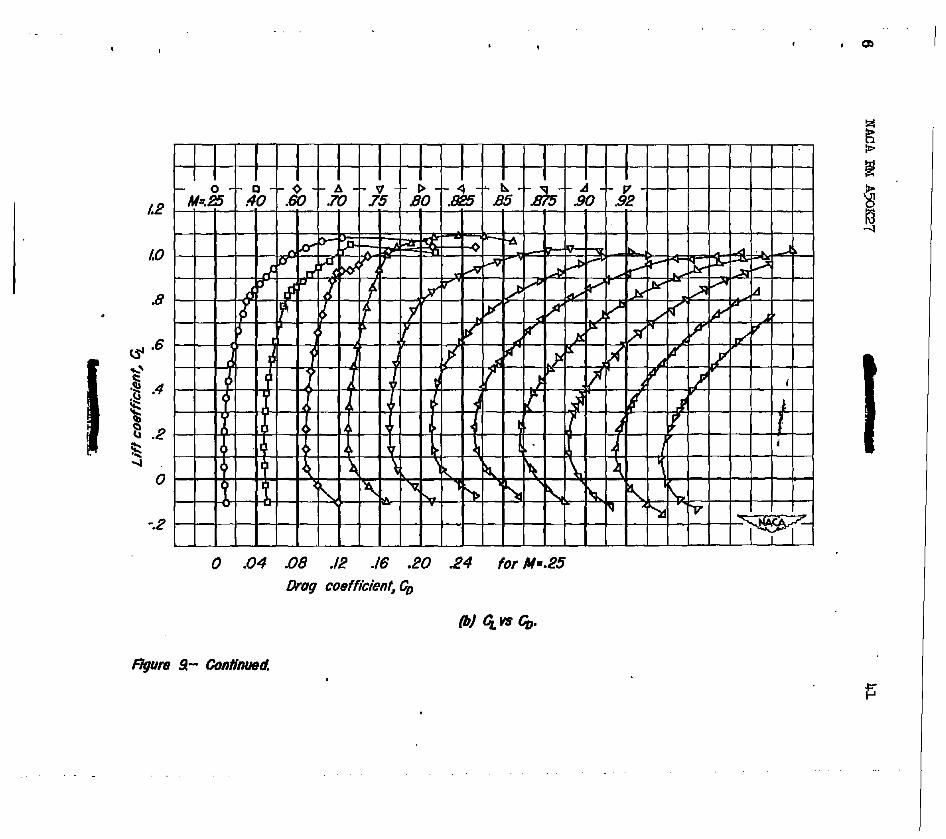
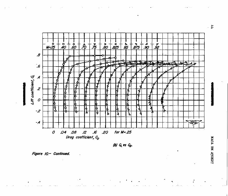
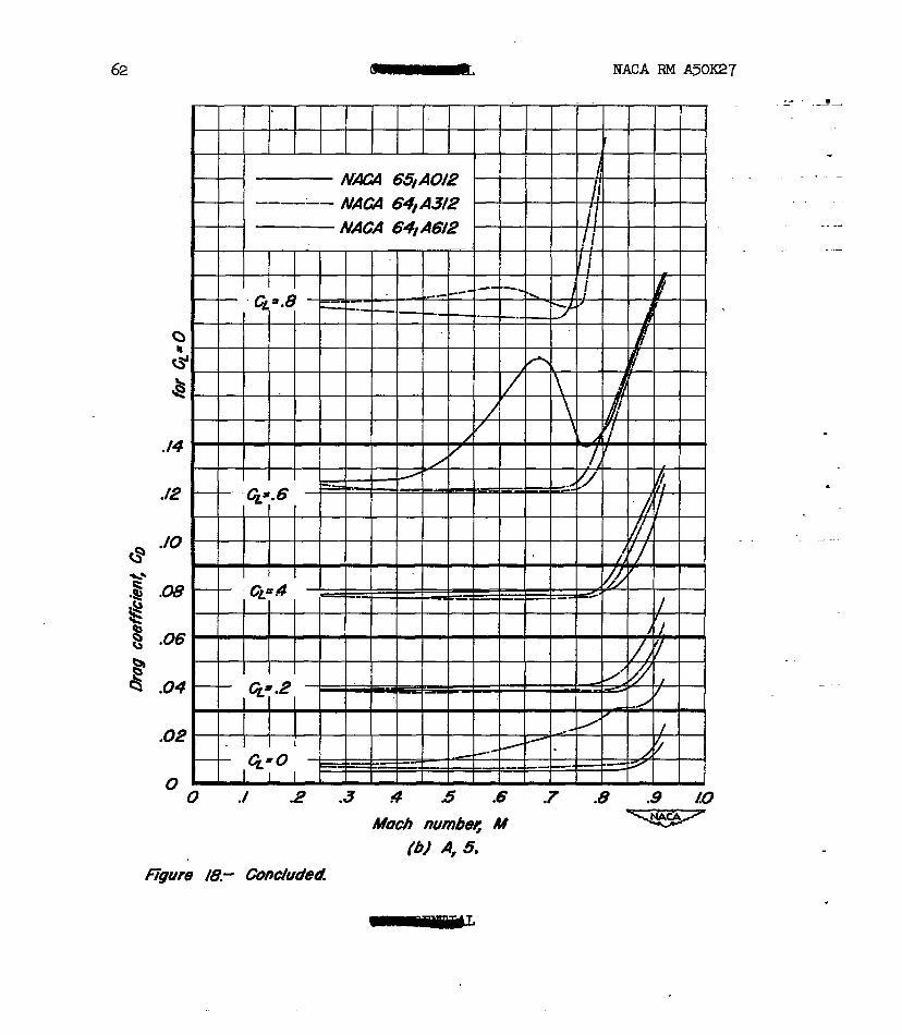
The drag coefficients of the six wTngs for eeveral lift coefficients are presented in figure 18 as Rmctions of Mach number, The Mach nmibers for drag divergence, specifically defined as the Mach nuzibers at wbioh % - = 0.1 from figure 18, are presented in the following table: a&t
r 1 I FL 1
0 .2
12 .8
A = 10 1 -
I BACA 6% A012
0.89 -87 .84
I 0.88 --- -85 0.82
i .82 .80 --- I :g 075 --- i .71
0.88 r 085 ..82 I --- l M-B
A=5
.75 ; .72
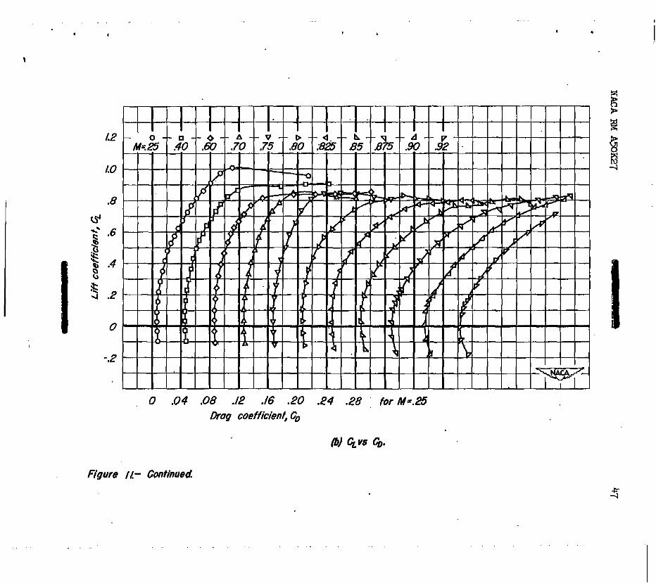
As would be anticipated from the results of tests of 64-series aixfoil sections reported in reference 10; the drag-divergenoe Mach Ilumber was, in general, reduced by caliber. At Mach numbers less than that for drag divergence, the effeot of cm&r was to reduce the drag for values of Uft coefficient greater thaaz 0.2. At a lift coefficient of 0.6, the drag of theuncsmberedtingswas large and e-t&c due to the proximity of this lift coefficient to the mazimm lift coefficient for thelse w9ngs. For the same reason, the drag of the moderately cambered wings was much greater than that of the highly~oambered wings for a lift coefficient of 0.8.
.
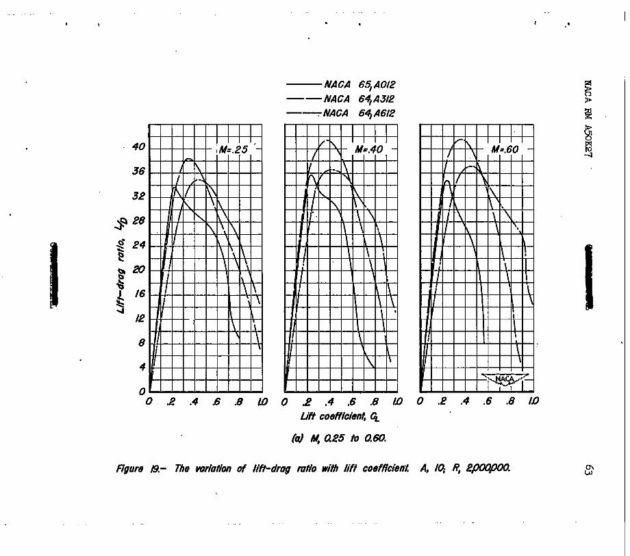
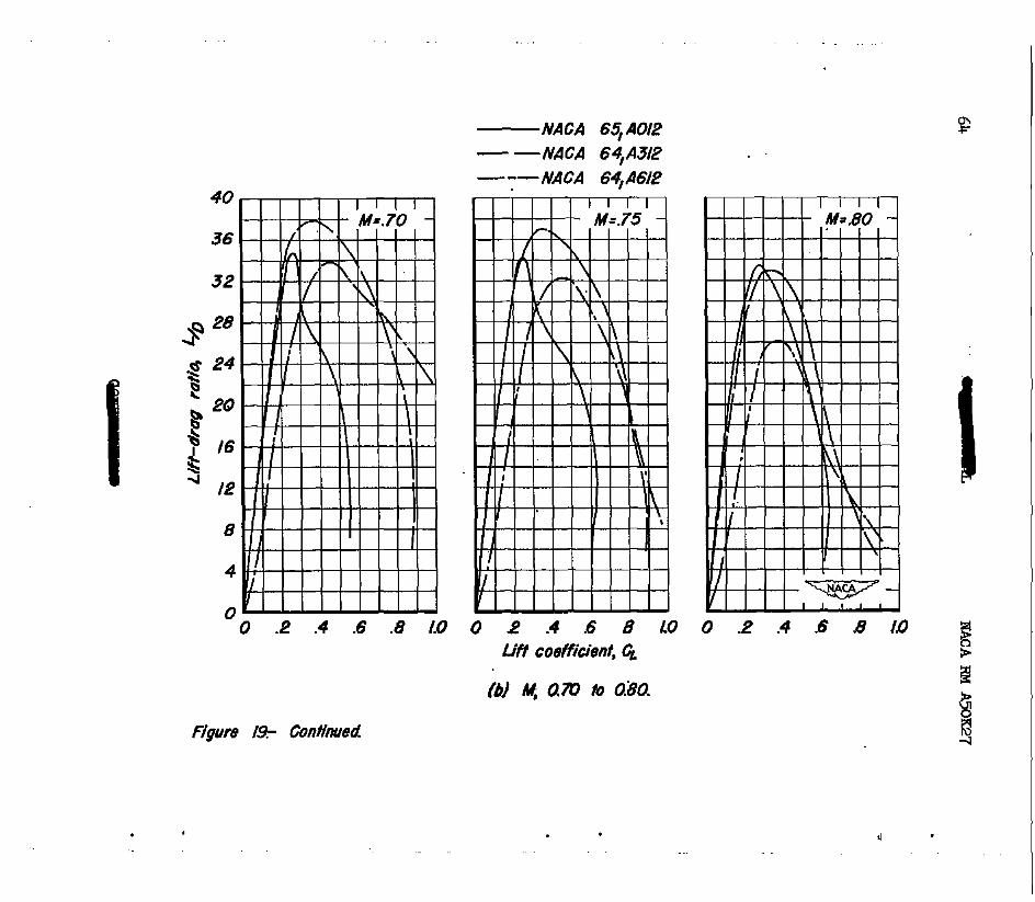
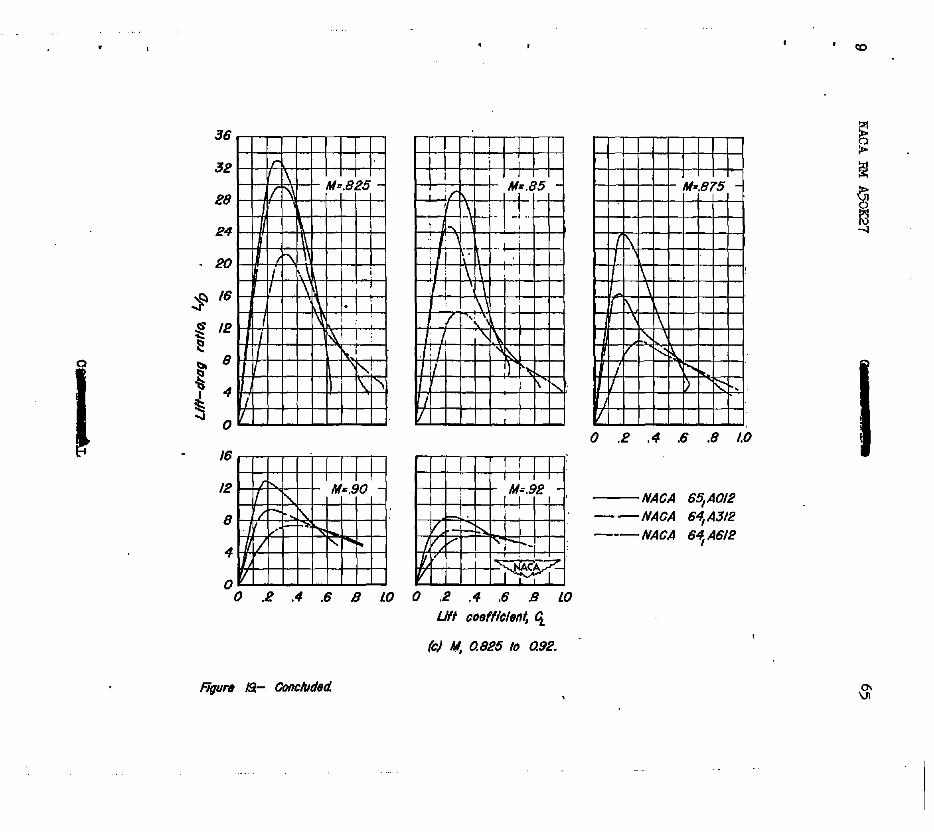
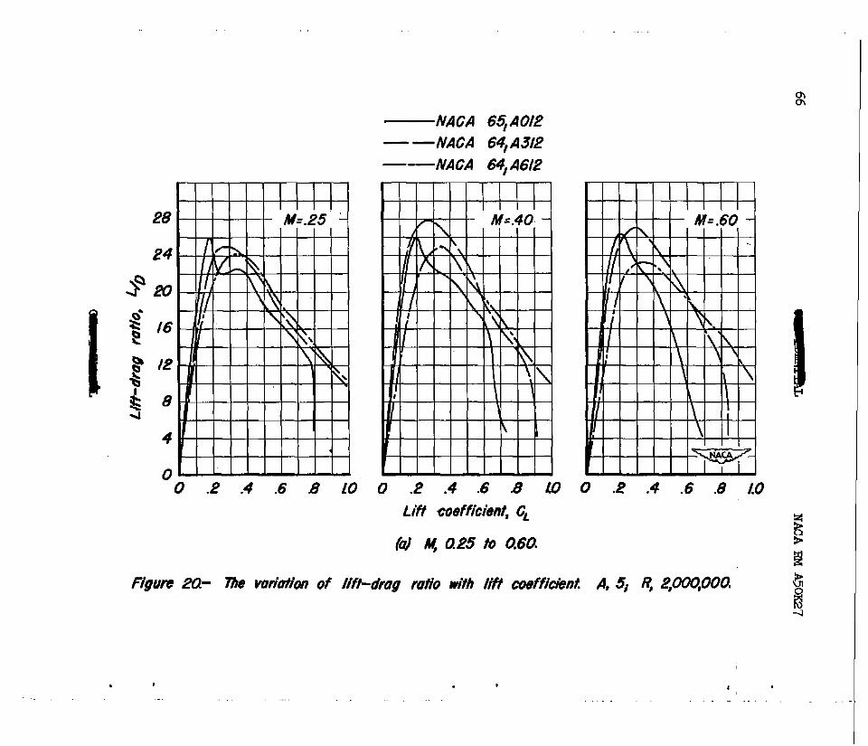
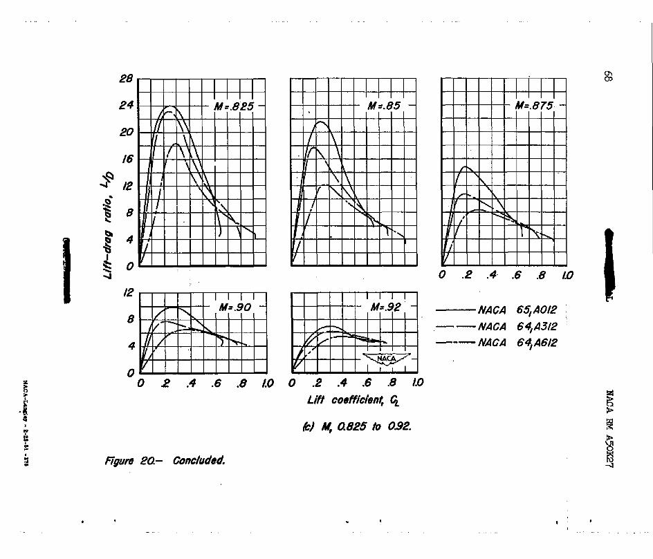
The variation of lif%drag ratio with lift coefficient is shown in figures 19 and 20. At Mach nmbers less than 0.80, the maximum lift+ drag ratio of the moderately cambered wing which had an aspect ratio of 10 was considerably greater than that of the uncekbered wing. The maxi- - mum lift-drag ratio of the highly caniseredwing which had an aspect ratio of 10, however, was only slightly greater than that for the uncam- bered wing at Mach nuzLbers less than 0.70. The improvement due to CLIP ber in the maximum lif+drag ratio of the wInga which had au aspect ratio of 5 wasless than that for the wings which had an aspect ratio of 30, In fact, no improvement due to camber for the wings having an aspect ratio of 5 was realized at Mach numbers greater than 0.60.

14 NACA RM A5OXC27
Caziber caused large increases in the liftrdrag ratio in the upper- lift-coefficient range. This was true for the wings of both aspect ratios provided the Mach nuztber for drag divergence was not exceeded, a result which would be anticipated from the results of tests of 64-series airfoil sections reported in reference l0.
It is emphasized, however, that the effects of Reynolds number must be considered in any attempt to assess the benefits derived from the use of caliber on these wings at the higher Mach nuzibers. The effects of ce ber on the static longitudinal stability and on the lift-drag ratio varied with the test Reynolds number. This variation maybe seen by comparing figures 14 and 15 (Reynolds number, lO,OOO,000) with figures 16, 19, and 20 (Reynolds ntmiber, 2,000,OOO). These data show that the improvement in the lift-drag ratio and in the pitchingiltoment character- istics due to camber were, in general, much smaller at a Reynolds nuuiber of 10,000,000. Therefore, there is considerable doubt that the improve- ments due to camber for lift coefficients less than the maximum of the uncambered xings, indicated to existat Mach nu&ers greater than 0.25 at a Reynolds number of 2,000,000, can be entirely realized at full- scale Reynolds numbers.
CONCuJsIONi
Six semispan model wings were tested: three having an aspect ratio of l0, and three having an aspect ratio of 5. W streamwise airfoil sections for the three wings of each aspect ratio were the NACA 65gm2, the R&CA 641A312j and the TUCA 641~6~. Results of this investigation indicated the following!
1. The effeots on the aer&ynamic che.racteristics of an increase in Reynolds ntuiiber from 2,OCO,OCC to lO,OCQ,OOO at a Mach nuriber of 0.25 were large.
2. For the wings having sn,aspeot ratio of 10, at a Reynolds num- ber of 1O,OoO,OCO and a Maoh nur&er of 0.25, the llEcdmm liftdrag ratio w&s improvedby Gamber. No similar ingxrovements were found for the wings havingsnaspeotratioof 5.
3. The effects of ca&er on the maximum lift coefficient, the angle of attack for zero lift, the pi~hing+nome nt ooefficient for zero lift, and the Maoh nur&er for drag divergence of these wings were consistent with those whioh would be anticipated from section aerodynamic character- ' istics.
NACARMA5OK27' 15
4. An abrupt decrease of the lift-curve slope, which was accow pauled by a large reduction in static longitudinal stability, occurred
c nearly simultaneously with drag divergence for all six wings.
5. At Mach nuuibers less than that for drag divergence and at a Reynolds number of 2,000,000, camber increased the lift-dreg ratio and the lift coefficient at which a decrease of static longitudinal stabil- ity occurred. If the effects of Reynolds number indicated by the low- speed test results prevail, however, these improvements at the higher Mach nmibers would not be entirely.realized at Reynolds numbers greater than 2,000,OCo. '.
Ames Aeronautical Laboratory, National Advisory Committee for Aeronautics,
Moffett Field, California.
RE??EWNCES
1. Jones, J. Lloyd, end Demele, Fred A.: Aerodynamic Study of a Wing- c Fuselage Combination Employing a Wing Swept Back 63?- Character
istics Throughout the Subsonic Speed Rauge with the Wing Cambered . and Twisted for a Uniform Ioad at a Lift Coefficient of 0.25. NACA RM A9D25, 1949.
2. Hun&, Lynn W.: k?ects of Twist and Camber on the Lo-peed Characteristics of a Larg&cale 45' Swept-Back Wing. NACA RM A5OU, 1950.
3. Abbott, Ira H., von Doe&off, Albert E., and Stivers, Louis S., Jr.: Summary of Airfoil Data. NACA Rep. 824, 1945.
4. Loftin, Laurence K., Jr.: Theoretical and Experimental Data for a Number of NACA 6Aseries Airfoil Sections. NACA Rep. 903, 1948.
1 (Formerly NACA TN 1368.)
5. Sivells, James C., and Deters, Owen J.: Jet-Boundary and Pie Form Corrections for Partial&pan Models with Reflection Plane, End Plate, or No End Plate in a Closed Circular Wind Tunnel. NACA Rep. 843, 1946.
6. DeYoung, John, and Harper, Charles W.: Theoretical Synunetric Span Loading at Subsonic Speeds for Wings Having Arbitrary Plan Form. NACA Rep. 921, 1948.
16 - NACA RMA50g27
7. Herriot, John G.: Blocka+p Corrections for ThreerDixmnsional~low Closed43moat Wind Tunnels, with Consideration of tbs Effect of Corqxressibility. NMA RM ~7~28, 1947.
8. Sprieter, JohnR., and Steffen, Paul J.: Effect of Mach and Reynolds Nmibers on Maximum Lift Coefficient. NACA TN 104.4, 1946.
9. Van Dyke, Milton D., end Wibbert, Gordon A.: HQh4peed Aerodynamic Characteristics of 12 Thin NACA 643eries Airfoils. NACA MR A5E'27, 1945.
10. Sum&s, James L'., and Treon, Stuart L.: The Effects of Amount and Type of Camber on the Variation with Mach Nmber of the Aerodynemic Characteristics .of a Xl-Percent-rPhick NACA 64A-6eries Airfoil
. Section. NACA m mg6, 1950.
.
Lul aLLmon6ioKl8 given in percent chord]
.
, ,
L4Jh?ns~ons sbom h inches unfess otbeftise noted
Aspect mH0 IO.07 Aspect ratio 5.14
/.I66 ff
Co&hates of tie a&W secbbns are Mdat’ed C tabh I


MX RM A~oIQ?. 21
=-foot pressure wind tunnel, Semispan model wing of aspect ratio 10 mounted in the &es
.8
-.4
-4 o 4 8 I2 16 20 .I2 .08 .04 0 ?04
Angle of attack, tqdeg Pitching-moment coeffich9nt , C,
figure 3.- me kft and pitching-moment characterisffcs at #HO &wmic pessures. A, r0,
airfoil sechW, MC4 6qAOl2; /i: 6jq - -
-4 0 4 8 I2 f6 20 .I2 .08 .04 0 ~04 0 04 .08 12
Angle of attack, U, deg Pitching-nwmeo f coefficient, c;,
ckag coefficient, G
.

-.2
I ’ L -8 -4 0 4 8 I2 16 20 24 .I2 .08 .04 0 304 ~08
0 .04 .08 .t2 .16 20 I%@ Of attack, 0; deg pitching-nment coefficient, t&
Drag mffmf, c,
01 4 f0; ainW e&on, tWG4 69A.312,
Lo
-8 -4 0 4 8 I2 I6 20 24 .I6 .I2 .08 .04 0 -.04 ~08 -.t2 ~16 0 -04 Lx3 .I2 J6
An& of attack, a, deg hag coofficiknt, 6
Id A, I@ mBWt se&q A#2 6+ASl2.
.
I
.8
-4 0 4 8 I2 16 20 .i8 .O4 0 704 0 .04 .08 J2 .16. -20
Angk of Mock, a, deg Fftchkrg-nwment meffitimt, c;, Drag coeff~<, 6
(d) A, 4 a&fM se&w, 6+4Of2.
3

. -4 0 4 8 I2 I6 20 24 .04 0 ~04 108 0 .04 .08 ./2 ./6 .20 .24 .28
Angle of ottuck, a, deg Pitchhg-moment coefficient, C,
Drag coefficient, CD
Figwe 4- Continued
_
1 . I I
I..
-.2
I I I I I I I I I I I I I I I I llllllllllllillll
I I I I I I I I I I .’ 11 !! 1 ! 11 11, B
-8 -4 0 4 8 I2 16 219 24 .04 0 504 708 .112 0 604 m&W I2 .I6 20 24
Angle of ottmk,. u, dep Bag coeft?&nt, G
pifchingmament coefficnt, qqj
fl 4 5j otPhV.1 eedhn, &%?A 6qA6Y2.
‘“ln- 40
36
32 32
28 28
24 24
20 20
I6 I6
I2 I2
8 8
4 4 -- i/ai;~’
0 0 .“‘II’-I 0 2 .4 .6 ,8 0 2 .4 .6 ,8 10 10
t? ~000,000
-- 4*ooqooo s,coo,ooo
-----/o,ooo,ooo
0 .2 .4 .6 .8 ID b2 L#t Coeffici8~, c;
hi’ A, H).
Figure 5.- 7i9e effect af Reynolds number on the lift-dreg mth at hw qeed M, 0.25
w 0

28
8
0 .2 .4 .6 B 10 A2
R 2,00QOO0
-- 4,OOQOOO --- 6,000,OOO --- f0,000,000
i i i i 0 .2 .4 .6 8 1.0 LP 0 .2 .4 .6 8 1.0 LP

. I
L2 .
.8
g -2 4
0
-.P
(a) A, IO.
@we 6- ?i% vofiatkm of ptvM~-ok7g co6fficienf and @ffching+wmenf coefMd wiH lift coefkiennll M, 0.2si AHhi sech NACA 6.3AOf2.
.
.
NACA RI4 A5CX27 33
.8
* .6
-.4
I I I I I t/l. f!rI I t I I I I I _I I x31 I I I i i i i i i i i i i Mi i I
0 .004 .008 .0/Z -016 .020 .024 .028 Prom-o!!og caef&iit, q-& .08 .04 0 -04
Pilb3rirgmomwf co&ci~, (in
Figure 6- Conchdea!
.8
. .
/ P / d IP I ,f I I I I IYI If I Y I , 7 1 A
-4 0 4 8 12 16 20 for Mu.25 Angle of dtack, a, deg
I?” iT- 77ie effect of Adaah number on tie wv@tnnic c&mcMstks. A, i0, t&h?&//
seti* lwa 6qAOl2; 4 gooqooo.
.

. I
LO
.8
rn.! t 2 t & I- 52 t ..?. t Q t 5 t v - - -,
’ 0’ .04 .08 ./2 ./6 .20 .24 for tit=,25 Drbp coetficient, C,
16
I I I I I I I I I I I I he.85 .40 2 2% .K h 25 k A5 .& SE I I I I I I I I I I I I
I I I I I I I I FlTlI
.24 .20 ./6 .I2 .a8 .04 0 :04 for Mr.25 pitching-momen/ coefLk&nt, C;,
ITpure r- Concluded.
W m

-.2
ri3iFi i i i i II
-4 0 ‘4 8 1’2 16 20 ‘24 for M~.25 . Angle of oftock, a, a&
/d C; Ys a.
figure 8.- 7he effect of Mach number on the aerodynamic chamcte&titi A, 10~ m.hW
secthn, M&A iM,A31P/ I( mOOa Y

12
LO
.8
-4
m-v .- .- .,I .,I , .W I.“IW 1 I” , ‘“V.-I w.. 1 . . ,
I I I I I I I I I I I I I I I I I I I I I I I
. - 0 114 .08 J2 .E 20 .24 fw Y=.B
Drag cssfficimi, G,
/.2
l.0
.8
I I I I I. I I I I I I I
Ah.25 30 .& .ib 25 Lb .& 8% &!5 ,& &
+- P
./2 .08 .04 0 ~04 ~08 -.I2 for A445 Pitching-moment coefficieent, C,
Figure 8.- &mcha#ed
I . -.2
-8 -4 0 4 8 12 16 ‘20 24 for b.25 Angle OfOttOGk, a, &g
ffgure St- ??I++ &t&t of M&I num&ef on Me oerodynam& charocteristicS 4 14 oirfrr secfioq
~6+=f4 6 WWQQ
-
* I
0 .04 .08 .f2 .i6 .20 24 for W.25 L4vg coefficient, C,
b2
-.2
I I I ItltlllIl1l1lllIltll~llllllllll~ II I I I I I I I I I I I I I II Ill
.04 0 ~04 -.OB 712 -.I6 for w=.25 Piichng-nnment coefficient, I& :
w CiK GQ. K

.6
-.4
, I I n Y 0 A d d d d n I I I
I I I
=FTT
-4 0 .4 8 12 16 for M=.25 Angie of attack, a, deg
Rgure IO- ?b effect of Mach number on the aerodpwmic charvctedstics 4 L$ airfcdl swtion,
NAM 6qAOle R, .$OOQOOa
.8
16
I I I
I. I I I I I I I I I 0 -- 0 -- 0 -- 4 -- v -- D -- Q -- b T- q -- A -- p --------- __ -- -- -- -- - -- --- -- --- -- --
@42? IqI.w(./pIq I.LpI&gIk55~.875~.37~.9g 1 1 1 1 1 ( 1 1 IIIII~IIIIIIIIIIIIIIIIIIIII III I
tiiii~~iiiP_~iiiiiiiiiiiiii i i I
I IXI IPI IXI IdI ldl IPI 1 d I ITI I R I I I I I I I
i
0 .04 .08 .I2 .ff .PO for AfR.25 Drag coeffic&t, CD
- c
. . - . 7
I

.6
-.2
-.4
04 0 ~04 708 712 Pitching-mtxnent coefficient, Cm
for MI.25
(cl G vs Gn.
Figure IO.- Concluded
I.2 --’ I I I I
hf.?& ‘.& 2 .^ I I I
-4 0 4 8 f2 I6 20 for iw.25, Angle of attack, O, deg
(a}Gvso.
figure /I- nte effect of Mach number on the aerodynamic choructerisfics. 4 S; oirfM
setifion, MICA 64/A3/2; R,, ~OoO,ooO
I
, i
.
_-
1
.8
0 .04 .08 .f2 .I6 .20 -24 .28 Mp.25 for LVag coefficient, C,
F/gum /I- Continued
-.2
I i i i i i i i i
.04 0 704 708 T/Z fw M=.25 Pitchihg-#meni coefficient, C;,
Figure /I.- Concfuded
. .

.
.8
-2
-.4 i i i i i i Ii i i i i i i i i i i i i i-i -8 -4 0 4 8 I2 16 20 for Ms.25
Angle of attack, a# deg
(oJ C; ~8 a. .
figure l2.- nte efhcf of Mach number on Me twtv&m7mlc characterisfh. A, Si &foil sectkq
/UK4 6+l6l.?j R, ~OOC&OO

Yl I I I I I I I I I I I II I I I I I I I I I
-- ‘A -- ,2 A& .& .& .m 2% ,-t&r
I I I I I&L
kg5 $5 & $5 &. , ‘y. , ( , , , , , , , ,
I I I I I I I I I I I I I I I I I I
I
I I I I I I t I I I I I I I I.1 I I I I I I I I I I I-+&&
-~4 I I . . 0 .04 .08 .I2 .I6 -20 -24 .28 for M=.25
Drop .coeB&nf, c, I
64) G vs co. 3
Figure f2.- Coniinued
.8
-.2
-.4 .w 0 394 $8 -.I2 -.I6 for Mm.25
pl/ching-mament coeffichwt, C&
/w 4 vs Gn.
figurn l2.- Concluded
52 - NACA FiM A5W27
I i i i. i i i i i i i i i i i T, i ‘ii I i\ i I 01 i i j i i i i i i i i i i i iii i ifii 1 I
./a L I \ I
.20 \,
)/ \/ ,
\ 1’ 1 , I L I\ I v ‘.l
.30
NACA 65,AO/Z ./O NACA 0.25 -- 64,A3/2
0.50 -- .08
.06
.08
.06
“0 ./ .2 .3 .4 .5 .6 .7 .8 .S LO Mach number, A4 =qixi&7.
/a) ,A, 10.
.
--
-- if
Figure /3.- 77w vo~iotions of fhe drag coefficienr, the lift-curve shpe,
and the pitching-moment-curve do- with Mach number:
HACA FN A50IL27 53
0
./O
.06 8 9 Y
.I0 NACA 6qA31’2 0.25------ .04 g 3
.08 NACA
6+A6/2 0.50
.02 f
.06 0
-04
.02
0 0 ./ .2 -3 d .5 .6 .i .8 .S 10
figure /I- Conducted.
i

$ .2
0
-.2 Y Y Y I I I 0 0
-.4 -py
-8 -4 0 4 8 f2 I6 20 -08 .04 0 ~04 708 s/2 :I6 0 .04 .08 .I2
Angfe of oPuck, a, deg pitchinpnmnent coefficient, f& hag coefficieni, CD
. .

. 1 -2
III 11 11 11 11 11 11 11 I I I I I I I I I I I I I I -1 I I I I .I
-8 4 0 4 8 12 I6 20 24 .2dO.q24 0 704 ~08 :I2 0 P4 .08 12 .I6
An@ of attack, a, deg RYChi~nnwhm coefficitulf, c;, Drag coeffmt, c,
NACA 69 AOt’Z - - NACA 641 A312 - - - NACA 64,A6/2
36
32
4
0 0 2 4 .6 .8 LO I2 0 .2 4 .6 .8 LO f2 L4 16
Lift coeffkfkn( CL
r
-.4
P Q Y d
yy=
-8 -4 0 4 8 12 I6 20 .M .oa .04 0 -04 -.08 712 :I6 0 -04 .08 .f2 .I6 .20
Angle of ohbck, q, $9~ RYchm-nnnnen t coeflfidMt, I& hlg ccdfmi,G
10) A, K).

-8 -4 0 4 8 I2 16 20 .oa .04 0 ~04 -.08 -.I2 0 .04 .08 .I2 .I6 .20 .24 .28
Angle of Mock, 0; deg fifch~gmcment coeffictin f, C;, Dmg coefficimt, I&
, .
1
.04
+2 % p -.04
li > -.08
t!
$ -./2 P ‘2 $ -.I6
--A--
-“---I-
---mm----
-----.-c-
-m--m
------
t I I I I I I I
.I .2 .3 .4 .5 .6 .7 3 3 t.0 Mach number, Al

NACA 6+46/2
6 I I
s es,6 ,-, 0.1 ----- I u 0.3 ------3 1 ) I I I I 1 I I I I I I
l-4 0.4 -mm-o---m
-20 % m-m-- m--w--
l I I I I I~-
0 I .2 .3 .4 .5 .6 Moth number M
(bl A, 5
.7 .8 .S LO
figure IiT- ctmhJ&?d
.

Ii ” ’ ” i i i i I MICA 651 A012
----.- NACA 64/A3/2 -- NACA 64/A612
0
G
-5
.14
A’ /
, 4 .
I ” ‘0
’ ’ ” I’ ./ .2 .3 4 5 .6 7 .8 .S 1.0
Hgute la- The vuriotion of drug coetXWent with Mach number for sevei
vu&es of lift coeff/o/enf. R, ~OOqooO
62 BJ NACA FM A5OIQ7
p 08 g Q\ 8 B
t i .06t j
i i j i
i i
i i I
j i h / VI
65/ A0/2 64, A3/2 64/ A612
I I I I I I I f t I I I w I I WI I I I i i i i i i i i i i i iii i I
.04
.
40
36
32
3 28
8
4
O- 0 a? .4 .6 .8 Lo 0 2 .4 .6 .8 l0
UH coefficlnnt, q
NACA 64 A012 --NCAA 64A3l2 -7 NACA 6q A612
,,[I I I I I I
I I I I I I
0 .2 .4 .6 .8 Ifi
32
I2
8
4
B-l
v 0 .2 .4 .6 .8 1.0
NACA 6s, AOi2 - - NACA 64, A312 ---NACA 64,A6l2
Figure I+ Conffhued
.
.
0 .2 .4 6 8 ID
1
. ,
36
I6
I2
8
4
0 0 .P .4 .6 8 10
0 .P .4 .6 .8 Lb
- NACA - - NACA --- NACA
0 .P .4 .6 3 10 LtYt coefflchnt, Q
fc/ AI, 0.825 to 092.
6s, A012 64/ A3t2 6$ A612
Fiuro w- Cmchded
,
0 .2 .4 .6 4 10
NACA 6s, A012
- -NACA 64,A3/P
---NACA 64, A6J2
0 .2 .4 .6 .8 u)
Lift coeffkient, CL
(4 hf 0.25 to 0.60.
Ylllll’llll 0 .2 .4 .6 .8 l.0
. ,

._ . .
32
28
p41 I I I I
II/I wthl I I I I I *
I /I\I\Y I I I I -1 -^ I I I I
H! ! I I:! ! !i!Y
0 .2 .4 .6 .6 10
NAGA Ss, A012 - - NACA 64A3f2
---NACA 6+A6/2
0 .2 .4 .6 .8 A0
Lift coefficient, li.
@) #f 070 Ib 0.80.
0 .2 .4 .6 .8 I.0
28
24
I6
I2
8
4
0
P I b
I/ i i i / / i / i
0 4 .4 .6 .8 1.0
rgutw PQ- Conchded.
.
0 .2 .4 .6 .8 1.0
Liff coefficient, G
k) M, 082.5 to 0.92.
.
0 .2 .4- .6 .8 I’D
NACA 6qAOl2 : -- NACA 64jA3f2 ’ --- NACA 6r7, A612