1 wireless technology in industrial...
TRANSCRIPT
1
Wireless Technology in Industrial NetworksAndreas Willig, Member, IEEE, Kirsten Matheus, Member, IEEE, Adam Wolisz, Senior
Member, IEEE
Appeared in Proceedings of the IEEE, Vol. 93 (2005), No. 6 (June), pp. 1130-1151
Abstract
With the success of wireless technologies in consumer electronics, standard wireless technologies
are envisioned for the deployment in industrial environments as well. Industrial applications involving
mobile subsystems or just the desire to save cabling make wireless technologies attractive. Nevertheless,
these applications often have stringent requirements on reliability and timing. In wired environments,
timing and reliability are well catered for by fieldbus systems (which are a mature technology designed to
enable communication between digital controllers and the sensors and actuators interfacing to a physical
process). When wireless links are included, reliability and timing requirements are significantly more
difficult to meet, due to the adverse properties of the radio channels.
In this paper we thus discuss some key issues coming up in wireless fieldbus and wireless industrial
communication systems: i) fundamental problems like achieving timely and reliable transmission despite
channel errors; ii) the usage of existing wireless technologies for this specific field of applications, and
iii) the creation of hybrid systems in which wireless stations are included into existing wired systems.
Index Terms
Fieldbus systems, real-time communications, wireless technologies, Bluetooth, IEEE 802.15.4, IEEE
802.11, hybrid systems
I. INTRODUCTION
The true convenience of being able to connect devices without the use of wires has lead to the
unprecedented success of wireless technologies in the consumer goods industry. Based on this success,
applications using these technologies are beginning to appear in various other settings as well. In an
Andreas Willig is with the Hasso-Plattner-Institute at the University of Potsdam.
Kirsten Matheus is with CARMEQ GmbH, Berlin.
Adam Wolisz is with the Telecommunication Networks Group (TKN) at the Technical University Berlin.

2
industrial or factory floor setting, for example, the benefits of using wireless technologies are manifold.
First of all, the cost and time needed for the installation and maintance of the large number of cables
normally required in such an environment can be substantially reduced, thus making plant setup and
reconfiguration more easy. This is especially important in harsh environments where chemicals, vibrations,
or moving parts exist that could potentially damage any sort of cabling. In terms of plant flexibility,
stationary systems can be wirelessly coupled to any mobile subsytems or mobile robots that may exist in
order to achieve a connectivity that would otherwise be impossible. Furthermore, the task of temporarily
accessing any of the machinery in the plant for diagnostic or programming purposes can be greatly
simplified by the use of these wireless technologies.
Along with the simplification of acessing machinery, many industrial applications exist that could
benefit from the use of wireless technologies. The localization and tracking of unfinished parts, the
coordination of autonomous transport vehicles and mobile robots [1]–[3], as well as applications involving
distributed control are all areas in which wireless technologies could be used in an industrial environment.
Many of these industrial applications are served by fieldbus systems [4]–[8] like PROFIBUS [9],
[10], WorldFIP [11], [12] or CAN [13], [14], which are wired. Fieldbus systems have been specifically
designed for solving automation or control tasks that rely on the interconnection of digital controllers
with other digital controllers as well as sensors and/or actuators (including their underlying physical
processes). The primary goal of these systems is to provide real-time communication services that are
both predictable and reliable, i.e. make certain guarantees on eventual delivery of packets and delivery
times. Some important characteristics of fieldbus traffic are: i) presence of cyclic (i.e. recurring) or even
periodic traffic (bounded jitter between subsequent packets required), subject to deadlines; ii) presence
of important acyclic packets like alarms, which need to be reliably transmitted with bounded latencies;
and iii) most packets are short, in the order of a few bytes. The protocol architecture of most fieldbus
systems covers only the physical layer, the data-link layer including the medium access control (MAC)
sublayer, and the application layer of the OSI reference model.
The obvious benefits of wireless transmission have led to a number of solutions. These solutions range
from voice-oriented, large-scale cellular networks such as UMTS, to data-oriented solutions like wireless
local area networks (WLAN), wireless personal area networks (WPAN) and wireless sensor networks.
WLAN systems, like the IEEE 802.11 family of standards [15]–[17], are designed to provide users with
high data rates (tens of Mbit/s) over ranges of tens to hundreds of meters. These parameters provide the
user with untethered access to Ethernet, for example. WPAN systems, such as Bluetooth [18], [19] and
IEEE 802.15.4 [20], [21], have been designed for connecting devices wirelessly, while taking energy-

3
efficiency into account. They support medium data rates in the order of hundreds of Kbit/s to a few
Mbit/s and have ranges on the order of a few meters. Many vendors offer equipment compliant to these
standards.
Running fieldbus-based applications with wireless technologies can be especially challenging. Since
wireless channels are prone to possible transmission errors caused by either channel outages (which occur
when the received signal strength drops below a critical threshold) and/or interference, the real-time and
reliability requirements are more likely to be jeopardized than they would be over a wired channel. This
is one of the key issues to be resolved in wireless fieldbus systems, or in general in the usage of wireless
technologies in industrial applications, and focus of this paper.
The goal of this paper is to give an overview of the problems and issues that arise when considering
the use of standardized wireless technologies like IEEE 802.11, Bluetooth, or IEEE 802.15.4 in a
fieldbus-controlled industrial network. The discussion of this topic takes the following structure. Section
II considers the adverse effect that transmission errors and other properties of the wireless channel have
on the timing and reliability of packet transmissions, irrespective of the specific wireless technology
used. These effects can be (partially) compensated for by either designing robust and loss-tolerant
applications / control algorithms or by trying to improve the channel quality when when designing a
wireless fieldbus protocol. We focus on taking the latter approach. Section III introduces the widely
used wireless technologies of interest for use by fieldbus systems in industrial environments: Bluetooth
[18], [19], IEEE 802.15.4 [20], [21] and IEEE 802.11 [15]. Given that users will most likely not want
to simply throw out their functioning wired fieldbus installations in favor of wireless ones, Section IV
discusses how wireless stations can be integrated into wired fieldbuses to create hybrid wired/wireless
fieldbus systems. Conclusions are provided in Section V.
Besides the issues discussed in this paper, there are further issues to consider in wireless fieldbus
systems. Two important ones are the following:
• Security: The wireless medium is an open medium and without countermeasures, it is easy for an
attacker to eavesdrop, to insert malicious packets, or to simply jam the medium, this way challenging
reliable and timely transmission. On the other hand, ensuring security goals like confidentiality or
accountability was not the main focus in the design of many fieldbus systems [22], [23]. The recent
trend to connect fieldbuses to the Internet by means of gateways has led to research towards securing
the gateway [24], [22], but it is also required to protect a fieldbus against attacks from the inside,
for example by employing proper encryption and authentication schemes.
• Energy supply and low power operation: In some fieldbus systems the same cable can be used

4
for communication purposes as well as to supply a station with energy. If the cabling were to
be dropped completely, alternative ways to supply stations with energy would have to be found.
Some options are wireless energy transmission [25], [26], energy-scavenging methods [27] or using
batteries. For battery-driven stations, energy is a scarce resource and should be used economically.
Replacing batteries may be infeasible or can lead to machine downtimes. Several mechanisms to
conserve energy in protocols and applications have been developed in the context of wireless (sensor)
networks [28]–[30]. In the design of fieldbus protocols, however, the main concern was real-time
communications, not energy-efficiency. There are efforts to combine both targets [31].
Wireless fieldbus systems and wireless industrial networks have created interest in both academia and
industry. The first publications date back to 1988 [32]. One of the earliest projects, the European Union
OLCHFA project, started in June 92 with the goal to provide wireless spread-spectrum transmission for
the WorldFIP (formerly just FIP) fieldbus [33], [34]. Today, several companies and consortia are active,
for example, the wireless industrial networking alliance (WINA), see www.wina.org.
II. FUNDAMENTAL PROBLEMS OF REAL-TIME AND FIELDBUS COMMUNICATION
This section introduces some of the fundamental properties of wireless transmission media, without
referring to any wireless technology in particular (this is done in the following Section III). Given
that there are a number of mature and commercially available (wired) fieldbus systems, the question is
whether there are major difficulties when using them with wireless media. Some examples discussed in
this section show that some protocols do indeed have difficulties. One particularly important problem is
channel errors; channel errors can cause packets to miss their deadlines, for instance. Accordingly, not
only are the consequences of errors of interest, but also the mechanisms that allow one to deal with
them. Some of these mechanisms, which have been been proposed specifically for fieldbus systems, will
be discussed.
A. Important Properties of Wireless Channels and Transceivers
1) Path Loss: The signal strength of a radio signal decreases with the distance between a transmitter
and a receiver. This decrease is known as path loss. The magnitude of the path loss depends on several
parameters, including the antenna technology, the frequencies used, and the environmental conditions
that are present. An often-used approximation of path loss is the log-distance model. In this model, the
received signal strength Pr at a distance d behaves as Pr(d) ∼ Pt ·(
d0
d
)γfor distances d larger than a
reference distance d0 and a radiated signal strength Pt. The reference distance depends on the antenna

5
technology. The so-called path-loss exponent γ typically assumes values between two (free-space path
loss) and six [35, Chap. 4], depending on the environment. In factory environments, path loss exponents
between two and three have been observed [35, Table 4.2], [36], but sometimes values smaller than two
can occur as well [37].
2) Half-duplex operation of transceivers: Wireless transceivers are not able to transmit and receive
simultaneously on the same channel because their own signals would drown all signals from any other
stations. Because of this fact, most wireless transceivers are half-duplex. They inhibit simultaneous
transmit and receive operations while allowing the same circuity to be shared, thus reducing the transceiver
complexity. The primary disadvantage of this approach is the time loss experienced from explicit receive-
transmit turnovers.
3) Physical layer overheads: To let the receiver of a packet acquire carrier-/bit-synchronization despite
a noisy channel, most wireless systems use extra training sequences of well-known symbols. When
the training sequence occurs at the beginning of a packet, it is called a preamble. For example, the
IEEE 802.11 physical layer with direct sequence spread spectrum (DSSS) requires preambles of 128 µs
length [15], transmitted with every packet.
Such physical layer overheads tend to be much smaller on wired transmission media.
4) Channel errors: A wireless transmitter propagates waveforms into multiple spatial directions at the
same time. These waveforms can be subject to reflections, diffraction, or scattering [35]. As a result,
multiple copies of the same waveform can reach the receiver after following different paths with different
relative lengths and different travel times (time dispersion). A common measure for such time dispersion
is the rms delay spread (root mean square), or simply delay spread for short.1. The time dispersion has
two important consequences:
• With small-scale or multipath fading [35, Chap. 5], multiple copies can interfere constructively
or destructively at the receiver. If a station (transmitter/receiver) or parts of the environment are
allowed to move, the composite signal at the receiver alternates between constructive and destructive
interference, leading to comparably fast fluctuations in received signal strength (time variance). In
the case of destructive interference, the channel is often said to be in a deep fade, and many errors
occur during the decoding of channel symbols. When the duration of a deep fade spans several
consecutive channel symbols, symbol/bit errors will begin to appear in bursts.
1The rms delay spread is obtained from the channel impulse response by measuring the excess delays and received signal
strengths of the second and subsequent received pulses relative to the time instant where the receiver gets the first pulse. The
rms delay spread is the standard deviation of the weighted (by signal strengths) excess delays.

6
• Inter-symbol interference (ISI): When the time dispersion is large, it can happen that waveforms
belonging to different symbols overlap at the receiver. In the case of such ISI particular effort is
necessary to reconstruct the original symbol.
There are further distortions to wireless waveforms, including co-channel interference and adjacent
channel interference from co-located wireless communication systems, thermal and man-made noise, as
well as Doppler shifts [35], [38], [39]. In industrial environments, significant noise as well as distortion of
transceiver circuitry can also be created by strong motors, static frequency changers, electrical discharge
devices, and more. Measurements of some key wireless channel characteristics in industrial environments
[36], [37], [40]–[44] have shown that the delay spread can reach values larger than 200 ns. Modulation
schemes with symbol rates of several Mbaud might then be subject to severe inter-symbol interference.
These phenomena translate into bit errors and packet losses, with possible delays if packets need
to be retransmitted. Packet losses occur when, for example, the receiver of a packet fails to acquire
carrier-synchronization or bit-synchronization, whereas bit errors refer to errors caused by flipped bits
after synchronization has already been successfully achieved [45]. The error characteristics shown by the
wireless channel depend on the propagation environment, the chosen modulation scheme, the transmit
power, the frequency in use, as well as many other parameters. In general, however, systems tend to
show time-variable and sometimes quite high error rates.
The following description gives an example of how severe such a situation might be. Measurements
in an industrial environment with an IEEE 802.11b-compliant chipset have shown that short-term bit
error rates in the order of 10−4 . . . 10−2 can be reached for a 2 Mbit/s QPSK modulation (Quaternary
Phase Shift Keying) [45]. Additionally, there are minute-long periods where packet loss rates of at least
10% (and sometimes up to 80%) have been observed. Also, bit errors and packet losses are “bursty”, i.e.
they occur in clusters with error-free periods (“runs”) between the clusters. Naturally, these results are
particular for the specific chipset and environment, but similar trends have also been observed in other
wireless measurement studies [46]–[49].
B. Some consequences of channel properties
1) Consistency problems: When a system uses the producer-distributor-consumer communication model,
like the WorldFIP [11], [12] fieldbus does, communication is based on unacknowledged broadcasts of
data identifiers (by the distributor), to which the station possessing the idenfified data item (the producer)

7
broadcasts its actual value.2 All consumers interested in this data can copy the received value into
an internal link-layer buffer for their applications. To achieve spatial consistency among a set of k
consumers, it is required that each of these k consumers receive the data value. Spatial consistency
is required, for example, when k distinct controllers work on the same physical process. Failure to
reach spatial consistency might lead to inconsistent control decisions among the controllers. Such spatial
inconsistency could occur, for example, if packets happen to be lost.
As an example, assume that the wireless channel is such that for every transmitter-receiver pair a packet
is corrupted independently with a certain probability p. When the producer has received the identifier
and broadcasts the data value, reaching spatial consistency requires that all k consumers receive the
data packet, which happens with probability (1 − p)k. As a numerical example: with p = 0.2 spatial
consistency between k = 4 consumers is reached with only ≈ 41% probability.
Another often-found requirement is relative temporal consistency. Consider, for example, a set of k
sensors sampling a physical process. To achieve relative temporal consistency, all the sensors must sample
the process within the same pre-specified time window. Some fieldbus systems, such as the PROFIBUS
DP [9], [10], use a broadcast-based approach to promote this kind of consistency. A controller broadcasts
a special control packet called FREEZE, which causes sensors to sample their environment immediately
and to buffer this value for later retrieval. Under the same assumptions as above, reaching relative temporal
consistency among k sensors happens only with probability (1 − p)k.
2) Problems for token-passing protocols: Fieldbus systems like the PROFIBUS [9], [10] rely on
distributed token passing in order to circulate the right to initiate transmissions between a number of
controllers (called master stations in PROFIBUS). The master stations are arranged in a logical ring
on top of a broadcast medium. It is shown in [50], [51] for PROFIBUS and in [52] for the similar
IEEE 802.4 token bus [53], that repeated losses of token packets are a severe problem for the stability
of the logical ring (ring stability). When a trial to pass the token from x to y fails, x is required to run
the next trial immediately. In case of bursty channels, however, it might well happen that the channel
between x and y is currently in a deep fade and will stay there for some time. This deep fade could
potentially render all successive trials for passing the token useless, causing y to become lost from the
2In the producer-distributor-consumer communication model data is identified instead of stations. A second common
communication model used in fieldbuses is the master-/slave scheme, as implemented, for example, in PROFIBUS [9]. In
this scheme communication happens between addressable stations. The master needs to know the address of the station (slave)
possessing a data item. It directs a request to the slave, and the slave has to respond to this immediatly. Slaves do not initiate
transmissions by their own.

8
ring. A master station y which has been lost from the ring has no transmit opportunities until it has
been explicitly re-included by another master. This re-inclusion can take multiple token circulations, and
packets arriving at master station y in the meantime will incur any corresponding delays. These delay
problems are much less pronounced when non-bursty channels having the same average packet error rate
are considered. Token passing protocols thus serve as an example for the fact that it is often not only
the raw presence of bit errors that is important, but also the characteristics (bursty vs. non-bursty) of the
errors as well.
Another problem with token-passing protocols is that the station passing a token and its successor in
the logical ring must be in mutual range. This stipulation cannot always be guaranteed when stations
are mobile. The fieldbus protocols based on token passing have no provisions to deal with mobility, and
appropriate mechanisms have to be added [54].
3) Problems for CSMA-based protocols: Fieldbus systems like CAN [13], [14] use CSMA-based
protocols where collisions are possible. In general, CSMA-based protocols [55] work in a distributed
fashion, where a station A wishing to transmit first needs to sense the transmission medium. If the
medium is determined to be idle, the station starts to transmit. The many CSMA-variants that exist,
differ in what happens when sensing the medium busy. In the option chosen for the CAN fieldbus, a
station A wishing to transmit waits for the end of the ongoing transmission and starts its own packet
immediately after it. Since another station B might do so as well, collisions can occur. The (wired) CAN
protocol is based on a deterministic mechanism to resolve this contention. This mechanism is difficult to
use for wireless media. It relies on a stations ability to transmit and receive simultaneously on the same
channel, which is impossible with half-duplex wireless transceivers.3
Receivers need a minimum received signal strength in order to successfully decode packets or determine
that another station is currently transmitting (carrier sensing). Due to path loss, the minimal signal
strength required is not reached once the distance between transmitter and receiver becomes too large.
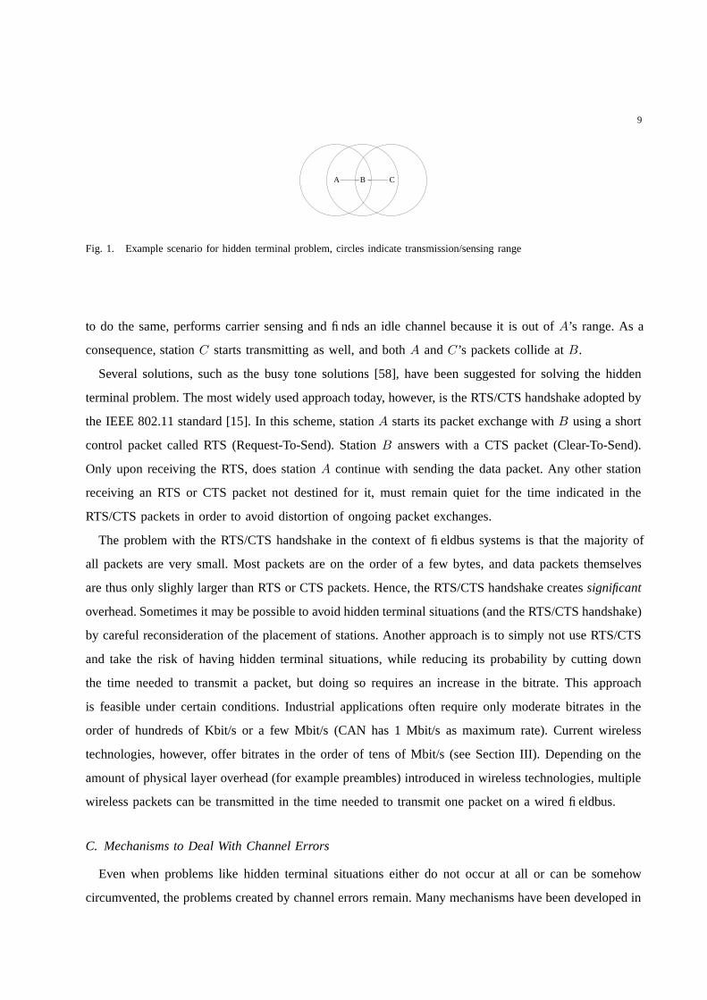
Accordingly, carrier-sensing operations may fail, giving rise to the hidden-terminal problem [58], from
which all CSMA-based (Carrier-Sense Multiple Access) protocols suffer. Consider three stations A, B
and C , arranged such that A and C cannot sense each others transmissions, but station B can receive
signals from both A and C (Figure 1). Station A currently transmits a packet to B. Station C wants
3The ultimate goal of CAN’s contention resolution procedure is to ensure that the station with the highest priority packet
wins contention. Such a feature is implementable on wireless channels, but different mechanisms have to be used (for example
[56], [57]). An additional problem to be solved is that of hidden terminal situations: how to make sure that two stations out of
mutual range agree on which one has the highest priority packet?
9
A B C
Fig. 1. Example scenario for hidden terminal problem, circles indicate transmission/sensing range
to do the same, performs carrier sensing and finds an idle channel because it is out of A’s range. As a
consequence, station C starts transmitting as well, and both A and C’s packets collide at B.
Several solutions, such as the busy tone solutions [58], have been suggested for solving the hidden
terminal problem. The most widely used approach today, however, is the RTS/CTS handshake adopted by
the IEEE 802.11 standard [15]. In this scheme, station A starts its packet exchange with B using a short
control packet called RTS (Request-To-Send). Station B answers with a CTS packet (Clear-To-Send).
Only upon receiving the RTS, does station A continue with sending the data packet. Any other station
receiving an RTS or CTS packet not destined for it, must remain quiet for the time indicated in the
RTS/CTS packets in order to avoid distortion of ongoing packet exchanges.
The problem with the RTS/CTS handshake in the context of fieldbus systems is that the majority of
all packets are very small. Most packets are on the order of a few bytes, and data packets themselves
are thus only slighly larger than RTS or CTS packets. Hence, the RTS/CTS handshake creates significant
overhead. Sometimes it may be possible to avoid hidden terminal situations (and the RTS/CTS handshake)
by careful reconsideration of the placement of stations. Another approach is to simply not use RTS/CTS
and take the risk of having hidden terminal situations, while reducing its probability by cutting down
the time needed to transmit a packet, but doing so requires an increase in the bitrate. This approach
is feasible under certain conditions. Industrial applications often require only moderate bitrates in the
order of hundreds of Kbit/s or a few Mbit/s (CAN has 1 Mbit/s as maximum rate). Current wireless
technologies, however, offer bitrates in the order of tens of Mbit/s (see Section III). Depending on the
amount of physical layer overhead (for example preambles) introduced in wireless technologies, multiple
wireless packets can be transmitted in the time needed to transmit one packet on a wired fieldbus.
C. Mechanisms to Deal With Channel Errors
Even when problems like hidden terminal situations either do not occur at all or can be somehow
circumvented, the problems created by channel errors remain. Many mechanisms have been developed in

10
the past to make data transmission over wireless channels more robust against the multitude of possible
impairments. It depends on the fieldbus system and communication model which of these mechanisms
are applicable.
Fieldbus systems working according to the producer-distributor-consumer model make extensive use
of broadcasting. There are no retransmissions, and, in general, the transmitter has no way to verify that
deadlines are met. Techniques where no feedback from the receiver to the transmitter is given, are known
as open-loop techniques. One useful approach is the forward error correction (FEC) coding [59]. In FEC
schemes, the transmitter adds redundant bits to the packet which allow the receiver to correct bit errors if
there are not too many of them. The ratio of user bits to the overall number of bits after encoding (user
bits plus overhead bits) is called the code rate. Roughly, the smaller the code rate, the higher the overhead
and the better the error correction capabilities. The rate of uncorrectable bit errors depends on the channel
bit error rate and the distribution of errors. One example is provided by Bluetooth (see Section III-A).
The interference created in situations where multiple piconets overlap leads to “almost binary” channels.
Such a channel alternates between excellent and very bad states. During excellent states, the overhead
of FEC is not needed, while at the same time the FEC may not be strong enough to correct all errors in
the bad state and the FEC overhead is not useful.
There are many other options for increasing robustness that do not require feedback (open-loop
mechanisms). Take for example: i) using multipath- and interference-resistant modulation schemes such
as orthogonal frequency division multiplexing (OFDM) [60] or spread spectrum modulation [61], [62]; ii)
transmitting a packet not only once but multiple times; or iii) optimizing unit placement and the number
of infrastructure equipment required (such as access points) [63], [64].
Some fieldbus systems, such as PROFIBUS, use retransmissions, and can give a transmitter some
control of whether deadlines are met or not. Protocols where the transmitter receives feedback from the
receiver and performs retransmissions when necessary, are commonly called automatic repeat request
(ARQ) protocols [65]. Because of the receiver giving feedback, they can also be classified as closed-
loop techniques. Retransmissions are useful when stringent reliability requirements have to be met that
cannot be reached by open-loop techniques alone (example: important alarm packets). Furthermore, in
contrast to open-loop FEC coding, ARQ protocols produce overhead only when it is needed to combat
errors. During good channel periods, there are no retransmissions and the overhead of ARQ protocols is
minimal. The available number of retransmissions, however, is naturally bounded by packet deadlines.
All the time the transmitter spends for retransmitting one packet is taken away from the deadlines of
other packets waiting to transmit. The quest in protocol design is, therefore, to find a good scheme that

11
improves the delivery reliability within a given deadline.
In the following section, we discuss selected open-loop and closed-loop protocol mechanisms. These
mechanisms have been proposed in the context of wireless fieldbus systems and wireless real-time
communications.
1) Exploiting spatial diversity: As has been explained, due to multipath fading, the received signal
strength is likely to change between receivers at different locations. Consider two receivers r and s,
which are the same distance away from a transmitter. If r and s are relatively close to each other, the
probability that r and s experience a deep fade at the same time is higher than if their distance is larger
than the so-called coherence distance.4 The channel behaviour is thus space-dependent, and this spatial
diversity can be exploited in a number of ways.
Receive diversity is an open-loop technique [66] where the receiver is equipped with multiple antennas.
The spacing of these antennas should take the anticipated coherence distance into account. When the
signal received by one antenna is in a deep fade, it can happen that the signal is good enough for proper
reception at another antenna if the antenna distance is large enough. The receiver is able to switch between
the antennas and can, for example, choose the one giving the strongest signal.
In transmit diversity schemes, the transmitter uses multiple antennas. There are transmit diversity
schemes working on the level of individual channel symbols (for example [67]). When commercially
available wireless network adapters are to be used, transmit diversity schemes working on the level of
whole packets become more interesting.
In the closed-loop scheme discussed in [68], the transmitter switches transmit antennas only in the case
of packet retransmissions. The first trial of a packet transmission is on antenna one, the first retransmission
on antenna two, the second retransmission on antenna three and so forth, in a round-robin fashion. This
approach is based on the assumption that, for bursty channel errors, it is better to switch to a spatially
different channel than to retransmit over the same channel and possibly encounter the same error burst
as the one hitting the original packet.
Sometimes, for reasons of cost or small form factors, it is not possible to equip stations with multiple
antennas. One alternative approach to achieve spatial diversity in the transmission process is to let other
stations help with retransmissions of packets [50]. When station A fails to transmit a packet to station
C , another station B might have picked up the packet and perform the retransmission on behalf of A.
4This coherence distance depends, among other parameters, on the antenna type and the propagation environment [35, Sec.
5.8.5], [66]. When multipath components can arrive from every direction, for example, a spacing between half a wavelength
and a full wavelength is sufficient to achieve diversity gains (compare [66]).

12
To avoid the required coordination between different possible helpers B1, B2, . . ., the role of B might
be confined to a dedicated station. Such schemes provide a kind of cooperative diversity [69].
The approaches to exploit spatial diversity in retransmissions have been shown to be effective in
reducing the probability of deadlines being missed [50], [68]. They work best, however, when the spatial
channels are independent/uncorrelated. This is a reasonable assumption to make, when multipath fading is
the dominant source of channel errors. When the receiving node is placed close to an interference source,
however, switching transmit antennas would most likely not be helpful because all spatial channels would
be affected.
2) Hybrid ARQ schemes: In hybrid ARQ schemes, retransmissions and error-correction coding (FEC)
can be combined in different ways [70]. In the simple type-I hybrid ARQ, all packets are FEC encoded
and always use the same code. When the receiver cannot correct all bit errors, it drops the packet and
requests a retransmission (up to a maximum number of trials per packet). In type-II hybrid ARQ, the
receiver does not simply drop erroneous packets but seeks to use the information contained in these
erroneous copies to help in the decoding of further retransmissions. A simple example of a type-II ARQ
scheme is bit-by-bit majority voting: Once the receiver has received at least three erroneous versions of
the same packet, it can guess what the received packet should be by subsequently applying a majority
voting procedure to all bits from previous trials. In [71], this method is varied by including the deadline
and desired delivery probability (see also [72]) in the choice of the actual coding schemes. Majority
voting is the last resort when no correct copy has been received before the deadline. Other schemes are
discussed for example in [73], [74].
A deadline-aware type-II ARQ scheme (“deadline-dependent coding”) is presented in [75]. The trans-
mitter maps the deadline for a packet and its desired delivery probability to one of several FEC coding
methods, creating a number of overhead bits for the data. On the occasion that a retransmission must
occur, the transmitter does not repeat the user data but rather sends more of the overhead bits. Such an
approach is called incremental redundancy.
In the strategy presented in [76], the coding method is chosen based on how far away the deadline
is. The closer the deadline comes, the stronger the chosen coding method (requiring more overhead bits)
becomes. This approach includes, as a “special” coding method, the decision to defer a retransmission
for a while. Such a postponing may avoid situations where energy and bandwidth are wasted when
transmitting a packet during a deep fade on a bursty channel.
Instead of changing the coding method that is used, the transmitter can also adapt the modulation
scheme (see [77] with a joint consideration for deadlines and energy consumption) or increase the transmit

13
power as the deadline comes closer.
3) An application layer mechanism: Sometimes it may not be possible for the lower layers to correct
all channel errors. For important asynchronous events, like alarms, this restriction is intolerable, For
periodic data sampling of a slowly varying, continuous process, one can simply accept occasional losses
or try to conceal them. One can, for example, replace missing samples at the receiver by an estimated
value. In [78], a scheme is proposed where the receiver estimates missing values on the basis of Kalman
filters. It is demonstrated that by this technique certain signal classes need only five out of 100 samples
to be able to reconstruct the orignial signal with good quality, and can be applied at the application layer.
D. Discussion
The wireless channel is a difficult environment. Some of the existing fieldbus protocols face serious
degradations in their achievable deadlines when dealing with bursty channels (compare the token-passing
example from Section II-B.2). Other protocols, on the other hand, are not directly implementable at all.
One example is the method used in the CSMA-based CAN protocol for resolving contention between
stations.
The wireless channel should influence the design of industrial applications. The fault assumptions, for
example, are different in wireless channels than in wired channels [72]. It is likely that errors occur
more often on wireless channels than on wired ones. Transmission errors on wireless channels, however,
tend to be transient (deep fades end at some time and the channel becomes good again), whereas errors
on wired channels are often of permanent nature, due to faulty cables, connectors, or other hardware
components.
Note that for some applications the rate of residual errors (after applying any countermeasures) has
to be kept at extremely low levels. “Fly-by-wireless” systems in aircrafts, for example, might require
residual error rates of 10−19 [72]. New protocol mechanisms or the combination of existing protocol
mechanisms are needed to achieve such low levels of residual error rates. Even if these levels become
achievable, it will likely require a tremendous amount of design effort. To reduce this effort, it is helpful
to relax the requirements posed to the communication system. This can be achieved, for example, by
designing industrial applications that can tolerate a certain percentage of packet losses or deadline misses.
This line of research is pursued in the area of networked control systems [79]–[81].

14
III. REVIEW OF WIRELESS TECHNOLOGIES FOR INDUSTRIAL AUTOMATION
For the various reasons listed at the beginning of the introduction, wireless technologies might be of
advantage in industrial environments. Due to the general tendency towards standardization and the fact
that cheap, commercial-of-the-shelf (COTS) wireless technologies are available, it seems only logical
to investigate these for their suitability in industrial deployment. Of particular interest for industrial
environments are technologies that do not require any sort of frequency licensing. These technologies
include the wireless personal area network (WPAN) technologies such as IEEE 802.15.1/Bluetooth and
IEEE 802.15.4/ZigBee as well as the wireless local area network (WLAN) technologies from the IEEE
802.11 family.
Despite the advantages a single wireless network might offer on the factory floor, it will be often
required to run multiple WLAN/WPAN networks in parallel in different or overlapping regions of the
plant. Because of this fact, the co-existence of multiple networks of either the same or varying types
needs to be investigated. We consider how certain communication patterns typical to those of fielddbus
systems can be implemented within such overlapping networks.
A. Bluetooth Technology/IEEE 802.15.1
Bluetooth (BT) was originally designed as a cable replacement technology aimed at providing effortless
wireless connectivity for consumer devices in an ad-hoc fashion [82] [83] [84] [85] [86]. In order to
allow for deployment almost worldwide, the BT Special Interest Group (SIG) placed the technology
in the unlicensed ISM-band (industrial, scientific and medical) at 2.4 GHz. By designing a comparably
straightforward system, the designers of BT intended for it to have widespread use.
Bluetooth networks are organized into ”piconets” in which a ”master” unit coordinates the traffic to
and from up to seven active ”slave” units. The master unit originates the request for a connection setup.
Within a single piconet, the various slave units can only communicate with each other via the master.
Nevertheless, every BT unit can be a member of up to four different piconets simultaneously (though
it can be master in only one of them). A formation in which several piconets are interlinked in such a
manner is called a ”scatternet”. Up till now, the role of scatternets is still relatively limited. Some of the
specific problems seen within scatternets are discussed in [87].
Piconet traffic is strictly organized into a time division multiple access/duplex scheme [88]. In this
scheme, the master is only allowed to start transmitting in odd numbered time slots (each slot is 625 µs
long), while slaves can only respond in even numbered slots after having been polled by a master packet.

15
Because there is no coordination between different piconets, packet collisions may occur if two piconets
are located near one another. To minimize this collision effect as well as to cope with the fact that
frequencies used by other devices on the radio channel can vary significantly over the bandwidth of
the 2.4 GHz ISM band, every piconet performs a rather fast frequency hopping (FH) scheme over 79
carries of 1 MHz bandwidth each. The maximum hopping frequency of this scheme is set at 1.6 kHz
(corresponding to the slot length of 625 µs) and the hop sequence used by each individual piconet is
derived from the unique address of its master using a specified algorithm. For each bluetooth packet sent,
a new frequency is chosen to send it over. In Bluetooth V. 1.2, an adaptive frequency hopping scheme
(AFH) has been introduced that allows for the exclusion of certain carriers once it has been noted that
packet corruption occurs at that carrier’s frequency. It must be noted, however, that AFH is used more as
a means to improve the performance of a BT piconet in the presence of other non-hopping systems in the
2.4 GHz ISM-band (see also Section III-D) than a way to improve the performance among co-existing
BT piconets.
On the physical layer (PHY), data is GFSK (Gaussian Frequency Shift Keying) modulated at 1 Mbit/s
and transmitted with a power of 0 dBm (1 mWatt). With such a transmit power, BT devices can expect to
have up to a nominal range of about 10m. Bluetooth can also be used with up to 20 dBm transmit power.
Transmitting at such high power results in a larger range, but requires implementing power control to
fulfill the sharing rules of the ISM-Band.
On the data link layer, a distinction is made between ACL (asynchronous connection-less) and SCO
(synchronous connection oriented) packets: ACL-links secure reliable data transmission with an automatic
repeat request (ARQ) scheme that initiates the retransmission of a packet in case the evaluation of the
included cyclic redundancy check (CRC) shows inconsistencies. Six different types of ACL-packets exist
and can occupy either one, three, or five BT time slots, depending on which type is being used. Three of
the ACL-packet types include uncoded payloads, while the other three have payloads that are protected
by rate-2/3 (code rate) forward error correction (FEC) that uses a shortened Hamming block code of
length 15 or 10 without any interleaving. The uncoded ACL-packet types are knowns as DH1, DH2,
and DH3, while the three coded ones are known as DM1, DM3, and DM5. Using packets of type DH5
for data and DH1 for acknowledgements gives the maximum possible (uni-directional) throughput for
Bluetooth at 723 Kbit/s.
SCO-links, in contrast, support real-time traffic by reserving time-slots at periodic intervals. Retrans-
missions are not allowed with these types of links, but in BT V. 1.2/2.0 ”extended” SCO-links have been
introduced where a limited number of retransmissions can be made. The three different types of SCO

16
packets all have the same length and require a time of 366 µs for transmission. They typically transport
64 Kbit/s of CVSD (continuous variable slope delta) encoded speech [89] and are differentiated by having
either unproteced payloads, rate-2/3 FEC encoded payloads, or rate-1/3 FEC encoded payloads. These
packet types are known as HV3, HV2, and HV1 respectively. The extended SCO-link is very flexible,
supporting various transmission rates. Lost SCO-packets can be replaced by an erasure pattern.
Because of the short range of BT and the small number of slaves that are active at any given time,
several independent BT piconets will most likely co-exist on a factory floor. With the help of radio
network simulations, Bluetooth-Bluetooth coexistence results have been presented in [90] [91] [92]. These
simulations took traffic, spatial node distribution, fading models, as well as co and adjacent channel effects
into consideration. Some of the results of these simulations have also been verified in a radio network
testbed [93], making them, therefore, more detailed than a purely theoretical approach.
The results have been obtained for an area of 10×20 m2, assuming an average master slave distance
of 2 m. Even though a factory floor generally is significantly larger, it is reasonable to assume that the
performance depends only on the node density and not on the absolute numbers of nodes or the area
covered. The considered area of 10×20m2 supports either 30 simultaneous, 1/3 loaded SCO connections
with an average packet loss rate of 1% or 100 (!) simultaneous WWW-sessions (bursty traffic with an
average data rate of 33.2 Kbit/s each) with a degradation of the aggregate throughput of only 5%. With
50 fully functional piconets in the area, a maximum aggregate throughput of 18 Mbit/s can be expected
when each individual piconet transmits at an average uni-directional data rate of 360 Kbit/s.
Furthermore, the results show that in the interference scenarios the provided FEC methods are unsuitable
to handle the almost binary character of the transmission channel. When two overlapping piconets operate
on different frequencies the signal quality is good, but when they hop to the same frequency, packets
can be destroyed beyond recognition. When using no coding method at all (as is the case with HV3,
DH1, DH2, and DH3), the power consumed by the network as well as the overall load of the network is
reduced. In order to obtain a good throughput and have low interference, it is disadvantageous to use short
packet types. This fact is unfortunate because short packets are typically used in industrial applications.
In fact, it is very hard to set up a scenario in which any other packet type yields a larger throughput than
that of DH5 [92].
These results present a basis on which the suitablity of using BT technology for specific applications
in a specific industrial environment can be investigated.
Security is supported in Bluetooth by the specification of authentication and encryption.
The most recent development for BT is Bluetooth V. 2.0 [94]. BT V. 2.0 has enhanced data rates using

17
π/4-DQPSK and 8DPSK modulation schemes in addition to the traditional GFSK modulation scheme.
The transmission rate resulting from these enhancements is about three times faster than it was in previous
versions of BT.
B. IEEE 802.15.4
The IEEE 802.15.4 standard [20] was finalized in October 2003 and specifies the characteristics of
the physical layer and the MAC layer of a radio networking stack. 5 The goal of this standard was
to create a very low cost, very low power, two-way wireless communication solution that meets the
unique requirements of sensors and control devices [20], [21]. In contrast to Bluetooth and IEEE 802.11,
IEEE 802.15.4 has been specifically developed for use with applications in which a static network exists
that has many infrequently used devices that transmit only small data packets. Such applications are
exactly what many industrial environments would require.
In order to encourage widespread deployment, IEEE 802.15.4 has been placed in unlicensed frequency
bands. When using the 2.4 GHz ISM band, IEEE 802.15.4 systems can get the same sort of global
deployment as Bluetooth and IEEE 802.11b/g systems. The IEEE 802.15.4 standard has also been
specified for use in the 868 MHz ISM-band in Europe and in the 915 MHz ISM-Band in North America.
Within these bands, direct sequence spread spectrum (DSSS) is used in order to comply with the respective
sharing rules of each band as well as to allow for simple analog circuitry to be used. The maximum data
rate of the DSSS is 250 Kbit/s in a single channel within the 2.4 GHz band. In total, the 2.4 GHz band
accommodates 16 such channels. In the 868 MHz ISM band one channel with a data rate of 20 Kbit/s is
available, whereas in the 915 MHz band ten channels of 40 Kbit/s each can be used. Because of various
system parameters, especially the MAC protocol that is in use, the maximum user data rate will most
likely be be about half of its nominal value, or less. If upper layers detect a throughput degradation while
using a specific channel within the used frequency band, IEEE 802.15.4 can scan the frequency band for
a channel that promises better perfomane values and switch to that channel [95] (unless transmitting in
the 868 MHz band).
The IEEE 802.15.4 standard differentiates between two different kinds of devices. A full-function
device (FFD) can become a network coordinator and can work with other FFD’s in a peer-to-peer fashion.
Reduced-function devices (RFD), on the other hand, are always associated with one of these FFDs and are
5There is sometimes confusion between IEEE 802.15.4 and ZigBee. The ZigBee alliance www.zigbee.org is a consortium
driven by industry and research institutions. It finalized the ZigBee specification in December 2004 and describes higher-layer
protocols (networking, application) that operate on top of IEEE 802.15.4.

18
GuaranteedTime Slots(GTS)
Superframe duration (configurable between 15.36 ms and 251.65 s)
Active Period Inactive Period
Contention Access Period
Beacon
Fig. 2. Superframe structure for IEEE 802.15.4 beaconed mode
limited to exchanging data with this device alone. Among RFDs there is no peer-to-peer communication
possible. All devices have a 64 bit address, but it’s possible for RFDs to obtain a 16 bit shorthand address
from their coordinator FFD.
With respect to the MAC protocol used by the IEEE 802.15.4 standard, there are two different modes
of operation. In unbeaconed mode all stations use an unslotted CSMA variant. Here, a station initiating
transmission of a packet does not perform carrier sensing immediately, but introduces a random waiting
time, called backoff time. Having such a backoff time facilitates the avoidance of collisions. In beaconed
mode (see Figure 2), the network coordinator imposes a superframe structure. The coordinator transmits
beacons periodically, choosing one of a number of configurable periods between 15.36 ms and 251.65 s.
The remaining superframe starts with the contention-access period, in which the RFDs access the medium
according to a slotted CSMA-CA variant, which incurs more overhead than the unslotted variant. An
optional contention free period is available, where the network coordinator allocates guaranteed time slots
(GTS) to individual RFDs for either uplink data or downlink data. In addition to these two modes of
operation, an inactive period of operation exists. During this period, all nodes including the coordinator
in the network are put to sleep in order to conserve energy.
Data packets are acknowledged and the protocol supports retransmissions, but there is no FEC coding.
In the beaconed mode the throughput is smaller than in the unbeaconed mode, in which no beacon frames
exist and the unslotted CSMA variant has less overhead. Under the conditions investigated in [96], the
maximum user data rate when running in the 2.4 GHz ISM band is 38 Kbit/s with one source, and up
to 70kbs when multiple sources are present. These observed data rates are, in fact, quite small.
Similar to Bluetooth, IEEE 802.15.4 uses low transmit power levels. In addition to this, IEEE 802.15.4
also uses very short symbol rates (up to 62.5 ksymbols/s), allowing the increased delay spread found in
industrial plants not to cause a problem.

19
For security purposes, IEEE 802.15.4 provides authentication, encryption, and integrity service. The
developer can choose between: No security, an access control list, and a 32 to 128 bit Advanced Encryption
Standard (AES) encryption with authentication.
C. IEEE 802.11 Technologies
IEEE 802.11 is comprised of a number of specifications that primarily define the physical and MAC
layers of WLAN systems [15] [16] [17] [97] [44]. Similar to other standards from the IEEE 802.x
series, the IEEE 802.11 MAC suggest the IEEE 802.2 logical link control (LLC) [98] as a standard
interface to higher layers. Since IEEE 802.11 is a WLAN standard, its key intentions are to provide
high throughput and a continuous network connection. Because of the focus on COTS technologies for
wireless connections in industrial deployments, only the most common variations and extensions of IEEE
802.11 systems will be discussed here. These variations and extensions include the general 802.11 MAC,
IEEE 802.11a, IEEE 802.11b, and IEEE 802.11g for physical layers, as well as relevant extensions in
respect to network planning and Quality of Service (QoS).
The main parameters of IEEE 802.11 a/b/g are the following:
• IEEE 802.11a [16] is placed in 5 GHz bands that are license exempt in Europe (5.15-5.35 GHz and
5.47-5.725 GHz) and unlicensed in the US (UNII bands, 5.15-5.35 GHz and 5.725-5.825 GHz).
Over the whole spectrum, this allows for 21 systems to be running in parallel in Europe and
eight in the US [99]. The IEEE 802.11a physical layer (PHY) is based on the multicarrier system
Orthogonal Frequency Division Multiplexing (OFDM) [60]. Seven modi are defined ranging from
BPSK modulation with rate-1/2 FEC and a 6 Mbit/s data rate, to 64-QAM modulation with rate-
3/4 FEC and a 54 Mbit/s data rate. The maximum user-visible rates depend on the packet sizes
transmitted. In the 54 Mbit/s mode, the transmission of Ethernet packets that are 1500 bytes long
results in a maximum user rate of about 30 Mbit/s, while sending packets with user payloads of
just 60 bytes results in a throughput of 2.6 Mbit/s [100]. The latter throughput value is the one of
interest for industrial applications, as small packet sizes are dominant in fieldbus networks.
• IEEE 802.11b [17] is a high rate extension to the original IEEE 802.11 DSSS mode and thus uses
the 2.4 GHz ISM band. Although in principle either 11 or 13 different center frequencies can be
used for the DSSS (depending on whether you are in the US or in Europe), only three systems can
actually operate in parallel. In addition to supporting the 1 and 2 Mbit/s modulation rates of the
basic IEEE 802.11 system, the payload of the IEEE 802.11b PHY allows for modulation with 5.5
and 11 Mbit/s Complementary Code Keying (CCK). The maximum user data rates are 7.11 Mbit/s

20
in the case of Ethernet packets and 0.75 Mbit/s in the case of packets with user payloads of 60
bytes in length.
• IEEE 802.11g is an extension to the IEEE 802.11b specification and is consequently also placed in
the 2.4 GHz band. It supports four different physical layers of which two are mandatory: the PHY
that is identical to IEEE 802.11b and an OFDM PHY that uses the same modulation and coding
combinations as IEEE 802.11a. Because of the different frequency band, the maximum user transmit
rates are about 26 Mbit/s for Ethernet packets and about 2 Mbit/s for packets with user payloads of
60 bytes when using the 54 Mbit/s modulation scheme.
It can be seen that when transmitting packets that contain small payloads (as is the case for most
fieldbus systems) throughput values are significantly reduced. This reduction is due to the comparably
large overhead of IEEE 802.11 packets and the different parameters present in the CSMA protocol [100].
In contrast to Bluetooth or IEEE 802.15.4, IEEE 802.11 has been specifically optimized to transmit
large data files, therefore showing a suboptimal performance when the majority of data is made up
of short control packets. Note that throughput values can decrease even more when additionally using
higher-layer protocols. Measurements for the throughput of TCP/IP traffic in Ethernet packets for the
IEEE 802.11b specification, for example, have returned results of a 5 Mbit/s maximum throughput
[101] [102]. IEEE 802.11 employs immediate MAC-layer acknowledgements and retransmissions. These
acknowledgement packets do not have to actually contend for the channel, instead, they have a reserved
time slot that is only used upon the reception of a correctly received packet.
In principle, it is possible to have IEEE 802.11 ad hoc networks that consist solely of mobile stations
(MS). It is more likely, however, that IEEE 802.11 will be used in an infrastructure mode, whereby
an access point(AP) relays all communications between stations and other networks. To organize the
traffic on the radio link, the IEEE 802.11 MAC provides two coordination functions. The first of these
coordination functions, the distributed coordination function (DCF), is mandatory and requires that all
stations compete for the channel according to a CSMA-CA protocol. When the carrier-sense mechanism
determines the channel to be free, a station may start to transmit. If the channel is sensed busy, the
station awaits the end of the ongoing transmission, where the channel becomes idle again. At this time
instant a random backoff timer is started. If the channel becomes busy before the timer expired the timer
freezes and restarts once the channel is idle again. If the timer expires and no other station has started
transmission in the meantime, the station starts transmission. The contention window from which the
backoff values are chosen increases exponentially after each failed trial to transmit a packet.
The basic CSMA-CA method can be enhanced with an optional RTS/CTS handshake to avoid hidden-

21
terminal situations. The user can control whether or not this handshake is used by configuring a threshold
for frame sizes. If a frame size exceeds this threshold, then RTS/CTS will be used, otherwise it will not.
The second coordination function, point coordination function (PCF) [15], is not mandatory, and is de-
signed to provide time-bounded services by means of subdividing time into (variable-length) superframes
which in turn are subdivided into a contention-free period (CFP) and a contention-period (CP). Within
the CFP, a polling scheme is used, while access is regulated according to the DCF during the CP. The
use of PCF is not very widespread6 and it has a reputation of being slightly inefficient [103], [104].
The IEEE 802.11 WLAN DCF was designed for “best effort” traffic like file transvers that is neither
time critical nor periodic. The PCF has difficulties to provide periodic services due to superframe
stretching (i.e. jitter in the start times of superframes) and foreshortened CFP’s [103]. For better support of
timing-sensitive transmissions, there is an ongoing activity – IEEE 802.11e – that extends the basic MAC
protocol [105] [106] [107]. In IEEE 802.11e, the Enhanced DCF (EDCF) is designed as an improvement
over the DCF. The EDCF allows to assign different basic contention window durations according to
the priority of a data packet, thus providing stochastic service differentiation (data packets with shorter
basic contention windows are more probable to obtain channel access than those with longer ones). The
PCF is improved upon with the introduction of the hybrid coordination function (HCF) that is not based
directly on polling, but by which the hybrid coordinator assigns time slots to stations on an explicit basis.
The stations can use these time slots as needed, but are restrained to the given time window. With this
restriction, the possibility to achieve periodicity is significantly improved.
Because of the existence of (metal) obstacles and the comparably large transmit power of 20 dBm, the
delay spread of a factory floor has to be looked at if IEEE 802.11 is to be used there. While the delay
spread in homes and offices is assumed to be < 50 ns and < 100 ns respectively, it takes on values of
200 to 300 ns in a factory floor setting (the delay spread is much less severe in Bluetooth due to its much
smaller transmit power and range). In the case of IEEE 802.11b, a conventional RAKE receiver supports
(only) about 60 ns delay spread in 11 Mbit/s mode and 200 ns in 5.5 Mbit/s mode [108]. Nevertheless,
more receiver algorithms with suitable robustness have recently come into existence [109] [110]. In case
of IEEE 802.11a or g, the situation is better. Because of the guard interval between channel symbols
inherent in the OFDM technology, delay spreads of several hundred nanoseconds can be supported easily
without paying attention to the receiver algorithms implemented [108].
When considering the overall network performance and not just the individual link performance (the
6The PCF is more complex to implement than the DCF and the authors know of no implementation that supports it.

22
interference performance is discussed in Section III-D), the number of publications presenting well-
founded results is limited. The existing ones, however, show that capacity is indeed an issue. The authors
in [111] [112] discuss how the aggregate throughput in a single network decreases with the number of
users, due to either hidden or exposed terminal problems7 or due to additional ”ready-to-send/clear-to-
send” (RTS/CTS) overhead. With only 10 stations [111] or a hidden node probability of 5% [112], the
system throughput is approximately halved (!) in the case of 1500 byte payloads (the smaller packet sizes
typical in fieldbuses are even less efficient).
When installing IEEE 802.11a in a cellular fashion, the situation can be simplified. First of all, there
is more bandwidth available in the 5 GHz band than in the 2.4 ISM-band. Secondly, a decentralized
channel selection algorithm has been standardized for IEEE 802.11a in IEEE 802.11h [99], organizing a
number of spatially overlapping networks to choose non-overlapping frequency bands. The most relevant
parameter for WLAN frequency planning is the number of mobile terminals that have to be served. From
this parameter, the optimum number of access points (AP) and distance between APs can be determined.
For security, IEEE 802.11 WLANs support several authentication processes which are listed in the
specification (none are mandatory).
D. Co-Existence of Wireless Technologies
In the future, it will be standard for multiple wireless technologies to be used in a single environment.
This is generally not a problem unless the technologies are placed in the same frequency band. As
the previous sections indicated, the 2.4 GHz band hosts Bluetooth, IEEE 802.15.4, IEEE 802.11b, and
possibly other systems. It is thus necessary to investigate the performance of co-existing networks and
to introduce methods for reducing mutual disturbances between them.
CSMA is, in principle, a mechanism for improving the coexistence of multiple communication systems
that use the same frequency band. In fact, the goal of the carrier-sensing operation is to avoid interfering
with ongoing transmissions. It depends, however, on the actual implementation of the carrier-sensing
mechanism whether transmissions of other types of wireless networks can be detected or not. In the
IEEE 802.15.4 standard, for example, the user can choose between different carrier-sensing modes [20,
Sec. 6.7.9]. In one of these modes, the carrier-sense circuitry indicates a busy medium when the received
signal energy is above some threshold. It does not matter if the received signal comes from another
7The hidden terminal problem has been discussed in Section II-B.3. In the exposed terminal problem: Station A wants to
transmit a packet to station C. Station A senses an interferer B and refrains from transmission, even when B’s signals do not
reach C. A possible transmission is thus suppressed.

23
IEEE 802.15.4 station, an IEEE 802.11 station, or any other device radiating in the same frequency band.
In one of the other carrier-sensing modes, it is required that the received signal be decoded properly,
i.e. use the right modulation scheme. In this mode, an IEEE 802.15.4 station can only detect ongoing
transmissions from other IEEE 802.15.4 stations and not from, say, an IEEE 802.11 station.
The interference between Bluetooth and IEEE 802.11b has been investigated extensively [101], [102],
[113]–[117]. In [118], it was found that IEEE 802.11b requires a carrier-to-interference ratio (CIR) of
about 10 dB to cope with a (narrow band) interference in its (wide) pass-band. Nevertheless, with IEEE
802.11a becoming more widely spread (especially in industrial environments) and the use of AFH for
Bluetooth V. 1.2, the interference situation is becoming much more relaxed. At least this is the case for
frequency static systems like IEEE 802.11. An IEEE 802.11 system transmits on a fixed set of Bluetooth
channels. When multiple AFH-enabled BT systems operate in parallel with an IEEE 802.11 network,
all of the BT systems stop using any of the channels occupied by the IEEE 802.11 network. The BT
systems now have to share the remaining channels. Since there are fewer available channels than in the
case without an IEEE 802.11 network, the BT systems create more interference to each other.
Along with the introduction of AFH, another coexistence improvement has been made to BT. In BT
V.1.0/1.1, the BT reverse link packet that contained the acknowledgement was transmitted on a different
frequency than that of the forward link packet. In doing so, the loss probablitiy in the case of a static
interferer was increased because the reverse link might hop into the interfered band even if the forward
link transmission was successful. With the BT V.1.2 AFH, forward and reverse link packets are now
transmitted on the same frequency, and such a situation will not occur anymore.
If a BT system and an IEEE 802.11b system are so close together that the 20 dB higher transmition
power of IEEE 802.11b blocks the BT receivers from receiving (when antennas are less than 20-30cm
apart), then only methods such as a joint scheduler can help to enable a fair coexistence [102].
Since IEEE 802.15.4 and IEEE 802.11b are frequency static and can be manually or automatically
made to use different frequency bands, the authors of [95] have concluded that IEEE 802.15.4 will have
little or no impact on IEEE 802.11b as long as some frequency management is deployed. Additionally,
typical IEEE 802.15.4 applications are expected to have a low duty cycle between 0.1% and 1% (meaning
that stations will transmit nothing for 99.9% or 99% of their time, respectively). Stations operating in
this duty cycle range do not create significant interference to other networks.

24
E. Comparison of Wireless Sytems
In the last few sections we examined three different systems. All three systems have been designed for
use in different scenarios, thus offering various advantages and disadvantages over one another depending
on their use. The 802.11 systems are suitable for transmitting large amounts of data. IEEE 802.15.4 is
suitable when communication is infrequent, small packet sizes are used, and power consumption is an
issue. Bluetooth fills the gap between these two by being able to transmit at medium data rates with a
lower power consumption than IEEE 802.11 (see also Table I).
Bluetooth/IEEE 802.15.1 IEEE 802.15.4 IEEE 802.11a/b/g
Range 10 (50-100m) 10m 50-100m
Throughput max. 723 Kbit/s ≤ 125 Kbit/s 30.6 Mbit/s (Ethernet), 2.6 Mbit/s (60 bytes payload)
Power consumption low very low medium
Periodic data yes (depending on polling algorithm) yes DCF: no; PCF: yes (with some jitter); HCF: yes
Retransmissions yes yes yes
FEC available no no
TABLE I
COMPARISON OF BLUETOOTH, IEEE 802.15.4 AND IEEE 802.11 TECHNOLOGIES
Although all three systems can be used on the factory floor, none of them will be able to run at their
nominal performance levels because of the adverse radio conditions that will be present. These conditions,
such as frequency-selective fading or interference, are especially prevalent if the system is placed in the
2.4 GHz ISM band.
Note that the effects of Doppler Shifts caused by mobility have not been considered. The velocity of
moving entities on the factory floor is expected to be too small to matter (not more than 20 km/h, see [40]
based on a user survey). Seamless connectivity of moving entities might require hand-over algorithms.
While for IEEE 802.11 roaming is specified in IEEE 802.11f (though with some performance limits
[119]), it is not covered in the specifications of Bluetooth and IEEE 802.15.4 (though not impossible to
realize).
F. Implementation of fieldbus services
When wireless fieldbus systems are to be implemented with one of the COTS technologies discussed
in this section, the fieldbus services and communication models have to be mapped to the services

25
and interfaces offered by these systems. We discuss mapping approaches for two of these technologies:
IEEE 802.11 with DCF, and Bluetooth.
1) IEEE 802.11 DCF: Even with problems like channel errors or hidden terminal situations taken
aside, the IEEE 802.11 DCF lacks predictability due to its stochastic access mechanism with random
backoff times and station contention.
One can eliminate contention by using a contention-free access mechanism such as polling8 or token-
passing on top of the IEEE 802.11 DCF. In the case of polling, for example, this can mean that a station
starts to use the DCF access mechanism only after receiving a poll packet. It is important to consider
whether the fieldbus packets should be embedded into unicast IEEE 802.11 packets or into broadcast
IEEE 802.11 packets:
• In the case of broadcast packets, there is no RTS/CTS handshake, there are no ACK frames, and
no MAC layer retransmissions are performed. Accordingly, the transmission of responses or the
initiation of retransmissions have to be implemented in higher layers. From the perspective of the
MAC layer, request and response packets are equivalent in the sense that the MAC entity has to
contend for the channel in the same way for both types of packets. This contention includes the
carrier-sensing operation. As a result, in the 802.11 DCF case, an acknowledgement or response
packet might be delayed by interference or traffic from co-located systems, causing the round-trip
time to become randomized. In fieldbus systems such as PROFIBUS [9], [10], on the other hand,
response or acknowledgement packets are sent immediately, and no carrier sensing is required. In
this type of system, the round-trip time is predictable.
• In the case of unicast packets, the RTS/CTS handshake can be switched off. All stations, however,
generate ACK frames automatically and the MAC layer performs retransmissions. These ACK frames
are not always useful. The PROFIBUS offers a mechanism, for example, where the responder can
place answer data directly into its MAC layer acknowledgement packet. This answer data is fetched
from a link-layer buffer, and it becomes the responsibility of the higher layers to write appropriate
data to this buffer. Such an immediate acknowledgement carrying data is not possible in IEEE 802.11,
however, since the ACK frames are always empty. To emulate this behavior, the responder must issue
a separate data packet for the response data. The overall transaction thus includes two extra ACK
packets.
8The “standard” solution for polling with IEEE 802.11, PCF, has not found widespread deployment. When only DCF equipment
is available, polling must be implemented separately.

26
The way in which the producer-distributor-consumer communication model ( [120], see also Section
II-B.1) can be implemented using the IEEE 802.11 DCF and the IEEE 802.2 Logical Link Control (LLC)
[98] protocol is investigated in [121]. The LLC is a common link layer protocol for the IEEE 802.x tech-
nologies.9 An additional Producer-Consumer-Protocol (PCP) uses the services of the LLC to implement
the producer-distributor-consumer mechanism. To query a data item, the distributor’s PCP entity first
broadcasts a packet containing the unique identifier of the data item. To achieve this broadcasting, the
distributor PCP entity requests the unacknowledged connectionless service of the LLC. The LLC, in turn,
maps this service request to an IEEE 802.11 MAC-layer broadcast and the packet is sent. When the MAC
entity of any station, y, receives this packet, it passes it on to its own LLC entity, and then on to its PCP
entity. If station y happens to be the producer, it gets the value of the data item. To send this data item,
station y then invokes the unacknowledged connectionless LLC service, eventually resulting in a MAC
layer broadcast. Any station receiving the data packet passes it on to its LLC entity and then on to its
local PCP entity. A station not interested in this data item drops it.
Since this approach is based on IEEE 802.11 MAC layer broadcasts, the data production requests and
the packets carrying the data items are not retransmitted. From the perspective of a consumer who is
interested in updates of a particular data item, two things are necessary for a successful update: The
producer must receive the production request, and the consumer must receive the broadcasted data item.
The time between two updates of a data item at a consumer is called the update time. Even when the
production requests have a perfectly constant spacing, channel errors will eventually turn this update time
into a random variable.
In master/slave systems like PROFIBUS-DP, there is a master cyclically exchanging data with a number
of slaves. Exchanging data means that the master can send data to the slave (for example data that the
slave should output to the physical environment) as well as receive input data from the slave. In addition,
a slave might want to issue asynchronous alarm events (called “diagnosis messages” in PROFIBUS-DP)
from time to time, in order to, for example, notify the master of unusual or dangerous conditions. If the
slaves are set to be purely passive devices, they can only notify the master about this alarm whenever
they are polled, by, for example, setting a special bit in the answer data packet.
Mechanisms to implement this behavior are considered in [122] for a monomaster scenario, using
9Together, the LLC and the different IEEE 802.x technologies cover the data link layer and the physical layer of the OSI
reference model. The IEEE 802.x technologies provide the physical layer and the MAC sublayer, whereas the LLC provides the
upper parts of the data link layer. It is comprised of mechanisms for error control, connection management, as well as others.

27
IEEE 802.11 DCF along with LLC. For cyclic polling of a slave, the master uses an acknowledged
connectionless LLC service. In this service, the higher layers on a slave device can prepare answer data
and place this into an LLC buffer. When the master sends its data packet, the LLC instance on the slave
responds with the data stored in this buffer. The LLC data packets of both the master and the slave devices
are mapped to IEEE 802.11 unicast packets. Since unicast packets are used, the MAC layer will send an
ACK for every received data packet. As discussed above, the slave is not able to send the response data
within the ACK frame, instead the whole channel access procedure must be invoked by the slave.
The handling of asynchronous alarm packets can be done in different ways. In [122], three methods
are proposed:
• In the late technique, the master collects all alarm notifications during a cycle and handles them at
the end of the cycle by separately polling each of the slaves in need.
• In the current technique, the slave replaces the cyclic answer data with the event data.
• In the immediate technique, the slave transmits the alarm packet by itself, without being polled. Since
the standard DCF access procedure is used, the slave contends with ongoing cyclic exchanges.
Interesting performance metrics for such a system are the mean update time of a cyclically polled data
item and the mean alarm latency. This alarm latency can be defined as the time between the occurence
of an alarm at a slave and reception of the alarm packet at the master. For a simple channel error model
that is loosing packets independently with a fixed probability p (varied between 0% and 10%), a fixed
number of stations, and the assumption that at most one slave has an outstanding alarm at any time,
it can be shown that all three techniques have similar mean update times. Also, the variance of the
update times is close together. With respect to mean alarm latency, the “immediate” technique is much
more advantageous than the “current” technique, which in turn is better than the “late” technique. The
“immediate” technique is dangerous in alarm shower10 situations, since not only do the alarms contend
with the cyclic traffic, but they also contend with each other, causing collisions to be more likely to
occur. These problems would be amplified in hidden terminal situations.
With respect to IEEE 802.11, it must be said that many proposals have been made to modify the
physical and/or MAC layer to better support deterministic or stochastic real-time services [123], [124],
[125]. Many of these proposals, however, necessitate modifications to existing networking equipment.
10An exceptional situation in the physical process or in the operation of controllers leads to the generation of alarm messages.
These messages may, as an aftereffect, lead to the generation of further alarm messages, and so on. Such a situation is called
an alarm shower.

28
While the upcoming IEEE 802.11e standard [105] offers promising features, further investigation is
needed to fully exploit the possible mappings of fieldbus services to the features offered by this standard.
One can only hope that 802.11e achieves better market penetration than PCF has.
2) Bluetooth: Due to its its polling-based MAC approach, Bluetooth [19], [126], [127] can be an
interesting candidate, when its inherent limitations (limited size of a piconet, moderate data rates) are
acceptable. The usage of Bluetooth in industrial and fieldbus applications has been considered in a number
of publications [128], [129], [130], [131].
In [130], the implementation of the monomaster PROFIBUS-DP using the services offered by the
Bluetooth L2CAP (Logical Link Control and Adaptation Protocol) is discussed. Both cyclic polling
and delivery of alarm packets are supported. The L2CAP offers a feature similar to the acknowledged
connectionless LLC service, by allowing the higher layers at a slave station to place a piece of data
into an L2CAP buffer. When the slave is polled by the master (the poll packet can contain data), it
answers in the very next time slot and includes the buffered response data in the answer packet. As
opposed to IEEE 802.11 with DCF, the slaves’ answer packet does not have to go through any channel
access mechanism. The proposed implementation for delivery of alarm packets is similar to the “current”
technique discussed above. The master polls all of its slaves in a cycle. When a poll packet fails, immediate
retransmissions are performed. Two performance metrics are investigated for this: the mean alarm latency
and the mean cycle time. Mean cycle time can be defined as the time between two successive polls
of the same slave. Because of possible retransmissions, the actual cycle time is a random variable. For
performance evaluation, it is assumed that the packet error rate between the master and a slave is constant.
When all channels have the same packet error rate, both the average cycle time and the average alarm
latency increase linearly with the number of slaves. When fixing the number of slaves, the average cycle
time and alarm latency grow to infinity as the packet error rate increases.
In [131], hybrid configurations consisting of Bluetooth-based monomaster PROFIBUS-DP over the
wireless medium, and either monomaster or multimaster Ethernet-based PROFIBUS-DP implementations
on the wired medium are considered, and metrics such as cycle times and alarm delays are investigated.
In [129], a co-channel interference model appropriate for multiple overlaid and unsynchronized piconets
is developed and is used for deriving the packet error rate seen by one piconet. This error rate is used
to derive probabilistic bounds on having a data/acknowledgement transaction miss a deadline.

29
IV. HYBRID WIRED / WIRELESS FIELDBUS SYSTEMS
In a hybrid wired/wireless fieldbus system, both wired stations (with transceivers being attached to
a cable) and wireless stations (having wireless transceivers) should be able to communicate with each
other.
In master/slave protocols, for example, a wired (wireless) master should be able to send a request to
a wireless (wired) slave and get a response back. Often, there are legacy wired fieldbus systems running
in a plant. The addition of wireless stations should not require any modifications to the protocols and
applications running on these wired stations.
The wireless interconnection of wired stations by means of encapsulating bridges has been considered
in [132]. The idea behind such an interconnection is to cut the cabling of a wired fieldbus system at
some point and insert a wireless link between the two ends (cable replacement). This cable replacement
is useful, for example, for placing a subset of a fully wired network on a mobile system, such as on a
portal crane or a guided vehicle. Such approaches are not discussed further in this article.
A segment is defined as a set of stations that are attached to a common medium, run the same protocols,
agree on transmission parameters, and thus are able to directly communicate. A wired segment consists
entirely of wired stations, while a wireless segment consists entirely of wireless stations. When two
wireless segments overlap in space, they need to be separated by some means, for example, by the use
of non-overlapping frequencies.
Wired and wireless segments are coupled through the use of a single or multiple coupling devices. It’s
possible for these devices to work on different layers of the OSI reference model. The main classes of
coupling devices in the realm of fieldbus systems are repeaters (working on the physical layer), bridges
(working on the data link layer) and gateways (application level) [133]–[135].
For real-time communications, the delay introduced by these coupling devices is important. In repeaters
and certain types of bridges, packets are forwarded from one segment to another with either no modifi-
cations to their contents or with only minor ones (for example to translate between different addressing
formats). Here, the forwarding delay can be defined as the time difference between the time instant at
which the last bit of a packet is received on the input segment and the time instant at which the last bit
of the packet was transmitted on the output segment. The forwarding delay depends on the type of the
device and the actual implementation of the forwarding operation:
• In cut-through forwarding, the transmission of signals on the output segment can start before the
packet has been fully received by the input segment.

30
• In store-and-forward forwarding, the coupling device starts to generate signals at the output segment
at some time after the whole packet has been received.
The origins and consequences of this forwarding delay are discussed in the following sections.
A. Cut-through forwarding
Cut-through forwarding is typically the mode of operation used by repeaters, but some types of bridges
can also be made to work in this mode.
1) Origins of forwarding delay: Some of the factors which must be taken into consideration when
designing cut-through devices include [136]:
• The media can have different frame format requirements. In the IEEE 802.11 DSSS physical layer,
for example, all frames are prepended with a 128 µs long preamble and a 64 µs long physical header,
independent of any MAC protocol. In the PROFIBUS RS-485 physical layer, there is no preamble
and no physical layer header. When a packet is to be forwarded from a PROFIBUS segment to an
IEEE 802.11 DSSS wireless segment, the data bits that are received during preamble generation
time must be buffered.
• The medium speeds may differ. Because of this difference, buffering is needed in both forwarding
directions. In the case of forwarding from a faster medium to a slower one, data bits arrive faster
than they can be output, and would get lost without buffering. The case of forwarding from a
slower medium to a faster one is different. Most media types require that bits be transmitted without
gaps between them. Because of this requirement, the coupling device cannot immediately start
transmission on its output medium once the reception of the packet on its input medium has begun.
Instead, the coupling device has to buffer the incoming bits from the slower medium and start
packet transmission to the faster medium at a later time. In the optimal case, the time at which this
transmission begins is chosen in such a way that the last bit from the slow medium will have been
received immediately before its time for transmission to the fast medium has come.
• Different systems can require different numbers of bits to be transmitted when a byte of data is to
be sent. In IEEE 802.11, transmission of a byte requires nothing more than transmitting the eight
bits of data contained in the byte. In PROFIBUS with an RS-485 medium, on the other hand, three
additional bits must be sent along with each byte so that serial communication can take place.
The forwarding delay incurred by a coupling device depends on both the actual combination of these
factors as well as on a number of other parameters, such as the processing delay or packet size.

31
To illustrate the influence of these factors, consider forwarding a packet from a slower RS-485
PROFIBUS physical layer with 1.5 Mbit/s data rate (no preambles, no physical layer header) to a faster 2
Mbit/s IEEE 802.11 DSSS physical layer with a total physical layer overhead of 128+64 = 192 µs. The
PROFIBUS uses eleven bits for a byte, the DSSS only eight. When the PROFIBUS packet has a size of
x = 10 bytes (110 bits), it remains on the PROFIBUS medium for approximately 110/1, 500, 000 ≈ 73.3
µs. Once the coupling device receives the first bit of the transmitted packet, it can start forwarding the
first bit immediately. Due to the physical layer overhead and the transmission time needed for 10 · 8 bits
at 2 Mbit/s, the packet leaves the forwarder after 232 µs. The forwarding delay is, therefore, ≈ 158.7
µs, more than twice the PROFIBUS packet duration. In contrast, when the packet has a size of x = 255
bytes, it takes 1.87 ms on the PROFIBUS, and only 1.212 ms on the wireless side. If the forwarding
device is able to determine the packet length, x, soon after reception of the packet on the wired side
has begun, it will be able to schedule the start of the packet transmission on the wireless side in an
optimized way. Specifically, the coupling device can schedule the start of packet transmission such that
the last bit of the packet will have been received from the wired medium immediately before it is to be
transmitted on the wireless medium. In doing so, the forwarding delay amounts to nothing more than the
transmission time of a single bit on the wireless medium, namely, 0.5 µs. In this scenario, forwarding
works well for large packets, but not so well for small packets. Since fieldbus systems tend to primarily
use smaller packets, the forwarding delays can become quite a serious problem.
A closer investigation of the forwarding delay with cut-through forwarding is presented in [136] for
forwarding that occurs between an RS485-based PROFIBUS and a physical layer developed within the
European union R-Fieldbus project [40], [137]. This physical layer has a shorter physical overhead
than the IEEE 802.11 DSSS. The results, however, can be transferred to other settings as well. One
interesting result is that the forwarding delay depends on the forwarding direction. Keeping the wired
transmission rate fixed at 1.5 Mbit/s, the wired-to-wireless forwarding delay decreases as the transmission
rate on the wireless side increases. In the reverse direction, however, the wireless-to-wired forwarding
delay increases as the wireless transmission rate increases. In both cases, the rate of decrease/increase
depends on the packet size. Consider a scenario where two wired stations, both with a 1.5 Mbit/s data
rate, communicate over a single wireless hop (thus having one wired-to-wireless conversion and one
wireless-to-wired conversion) [136]. In this scenario, the wireless medium should have a transmission
rate between 1.1 and 1.2 Mbit/s in order to achieve a close-to-optimal forwarding delay for all packet
sizes under consideration. Outside this range, larger packets are subject to high forwarding delays.

32
Cut-through forwarding schemes typically have the smallest forwarding delays in comparison with
store-and-forward or gateway-based approaches.
B. Store-and-forward forwarding
In store-and-forward (S+F) systems, forwarding devices first receive an entire packet on the input
segment, before forwarding it to the output segments. The minimum forwarding delay is thus given by
the time needed to send the packet on the output segment, plus any additional processing time required
by the forwarder. When using the numbers from the example given above, the small packet with x = 10
bytes has a forwarding delay of 232 µs, and the large packet with x = 255 bytes has a forwarding delay
of 1.212 ms.
If the forwarding device is a bridge, it might be necessary to contend with other stations on the output
segment for the right to transmit. When the output segment is a token-passing ring, for example, the
forwarder must receive a token before it can transmit the packet any further. This kind of delay is referred
to as medium access delay. Frequently, the medium access delay is variable. In this case, the forwarding
delay is also variable, even when packets of the same size are the only ones used.
The forwarding delays in S+F approaches tend to be, therefore, larger than for cut-through approaches.
The computation of any upper bounds requires knowledge of the upper bounds for the medium access
delay.
C. Consequences of Forwarding Delay and Speed Differences
The presence of forwarding delay and different medium speeds has some important consequences.
1) Handling of Link-Layer Timeouts: In systems using master-/slave communication, a master unit
sends a request packet to a slave unit and expects the response within a certain amount of time (link
layer timeout, or timeout for short). In the presence of forwarding devices, such a request-response
exchange takes more time than would be necessary on a single medium. There are two options for
setting these timeouts:
• To set it large enough to accommodate the worst-case round-trip time between a master and slaves,
taking into account all forwarding delays. The drawback of this approach is the reduced responsive-
ness to transmission errors. The detection of a missing response (even from a slave within the same
segment) takes much longer than it would if there were just a single segment and short timeouts.
Due to the probability of transmission errors on wireless media, this delay can become critical if
wireless links are involved.

33
Resp1 Req2 Resp2 Resp3
Resp3Req1 Resp1 Req2 Resp2
Req1
Segment 1
Segment 2
Req3
Req3
Fig. 3. Example for queueing delay induced by coupling devices
• Select the timeout to be the same as the timeout for single-segment networks without any forwarders.
When a request issued by station A is addressed to station B located in a distant segment, this timeout
will be too small to accommodate for the round-trip time. One option to deal with this problem is to
avoid letting A retransmit its request packet. The forwarder F1, closest to A, responds to A’s request
with a special “response-comes-later” packet [138]. If B is located on another segment attached to
F1, F1 acquires B’s response and forwards it on to A. No further action of A is required. If B is not
located in a segment attached to F1, F1 directs its request to another forwarder F2, gets a “response-
comes-later” packet, and the process continues. A drawback to this approach is that existing fieldbus
protocols typically do not contain such a mechanism. Without this mechanism, exisiting protocols
would have to be modified, and wireless links would no longer be able to be seamlessly integrated
into them.
2) Queueing Effects: The presence of preambles or different speeds on the medium can have the
effect that two identical packets have different transmission times on different media. Because of this
fact, queuing delays are now going to be present [139], [140]. An example illustrating these delays can
be seen in Figure 3. Assume a producer-distributor-consumer system. There are two different segment
types, S1 and S2. The distributor and the producers for requests Req1 and Req2 are located in segment
S1, the producer for request Req3 is located in segment S2, and consumers are spread throughout S1
and S2. It is assumed that both production requests and producer responses have a duration of t1 seconds
on segment S1. On segment S2 these same packets have a duration of t2 > t1 seconds. As seen in the
Figure, the forwarding delay (indicated by the dashed lines) increases over time. The packets the coupling
device receives from S1 that it needs to forward to S2 will be buffered in a queue. If the distributor
issues a third production request Req3 for a variable produced by a station in S2, the request packet
experiences a queueing delay in the forwarding device.
Similar situations can also occur in master-/slave systems such as PROFIBUS. A solution developed
for such systems (but applicable to other systems as well) is the insertion of extra idle times between

34
requests [139], [140]. With reference to Figure 3, the distributor, after receiving response one, waits for
an additional time before issuing request two.11
3) Relative Temporal Consistency: Some systems rely on broadcast packets to achieve relative temporal
consistency. The communication between a set of sensors sampling the physical environment, for example,
requires such a consistency (see Section II-B.1). If the sensors were to belong to different segments,
however, the temporal consistency could be jeopardized by the fact that the forwarding delay introduces
additional jitter between the sampling instants.
One solution would be to keep all stations synchronized to a common time reference and instruct
them to sample at an explicitly specified time. The price to pay, however, is the introduction of a time
synchronization protocol (see [29, Chap. 8] for a survey) and the need for hardware clock circuitry even
in small sensors.
D. Repeaters vs. Bridges
Repeaters essentially convert the physical representation of signals from one type of medium to another.
They usually work in cut-through mode, but store-and-forward is also possible. Since repeaters operate
essentially on the physical layer, there are no medium access delays. The segments connected by a
repeater run the same MAC protocol and form a single network. The protocol stack of the stations does
not need to be changed, except maybe for certain configuration settings such as link-layer timeouts.
Repeater-based solutions do, however, expose wired stations to the errors present in the wireless channel.
Bridges operate on the data-link layer. Their precise operation depends on the similarity between the
layers on either side of them [134], [135]. Bridges often operate in S+F mode and place restrictions on
forwarding. As an example: i) when the input packet is corrupted (e.g. checksum failure), forwarding
is suppressed; and ii) when the destination station of a packet is known to be in the input segment, no
forwarding is necessary.12 The ability to avoid forwarding for intra-segment traffic has different benefits:
• Intra-segment traffic can be handled with the lowest possible response times and small timeouts. In
11When there are only unicast packets in a master-/slave system, there is no need for extra idle times when the forwarding
device can filter packets based on addresses. Referring to the example, the forwarder would not forward the first two requests
and responses to segment S2.
12To achieve this, the bridge has to learn which stations can be found in which segments. Such detection can be done, for
example, by snooping packets and exchanging information with other bridges [134]. Additional mechanisms (spanning tree
construction) are needed to avoid forwarding loops. When the address fields of a packet are placed at its beginning (which is
common), a filtering bridge can also work in cut-through mode.
35
addition, when multiple unacknowledged packets need to be transmitted in a series within the same
segment, no extra idle times have to be inserted.
• Intra-segment traffic can be handled simultaneously in different segments, increasing the overall
traffic capacity. In order to exploit this increase in capacity, the allocation of stations to various
segments should take the anticipated traffic into account.
• As far as intra-segment traffic is concerned, errors on wireless media can be confined completely to
a wireless segment.
E. Gateway-Based Approaches
Sometimes it may not be possible to use any forwarding device. In WorldFIP, for example, with
its producer-distributor-consumer model, the producer of a data item must respond to a distributor’s
generation request within 70 bit periods [141], where one bit period is equal to the inverse of the data
rate. If the distributor’s wired segment runs at a speed of 2.5 Mbit/s, only 28 µs are available for the
request to be answered. Asuming the producer is a wireless station in a neighboring wireless segment,
two forwarding steps would be needed, including all the forwarding delay, preambles and so forth. Going
through these steps would take much longer than 28 µs when commercially available equipment is used.
In gateway-based approaches, different segments are typically coupled by a dedicated application
running in a gateway station. This application connects to different segments, each running a separate
fieldbus protocol stack. The dedicated application interacts with the application layer services of these
different protocol stacks to allow communication between segments to take place.
Consider the case where two segments S1 and S2, coupled by a gateway, use a fieldbus protocol based
on a master-slave scheme. When master A (located in S1) issues a request addressed to slave B (located
in S2), the gateway can intercept A’s request and become a master to B itself. The gateway then receives
B’s response and generates a response packet for A. Such an approach requires, however, large timeout
values for the link-layer of master A. The disadvantages of having such a large timeout value were
discussed in Section IV-C.
An alternative to this approach is to let the gateway generate the response to the masters request from
a cache, thus acting as a proxy. This approach is applicable in master-slave and in producer-(distributor)-
consumer systems. The method presented in [142] for WorldFIP uses a wireless-to-wired gateway that
serves as a central base station for the wireless part. The medium access control (MAC) protocol on
the wireless side is based on a time division multiple access (TDMA) scheme. The base station is
responsible for caching all process variables produced by wireless stations (acting as a consumer here),

36
and for becoming a producer for these variables on the wired part. The same is done in the other direction.
F. Case study: PROFIBUS
The PROFIBUS is a particularly interesting example for studying hybrid network architectures, since
a variety of different approaches have been developed for this system. Some of these approaches were
developed in the context of the European Union R-Fieldbus project [40], [137]. In the following sections
these approaches are briefly described.
1) Single-Logical-Ring Solution: All wired and wireless segments are coupled by repeaters into a
single broadcast domain. All stations run the PROFIBUS token-passing protocol and are organized into
a single logical token-passing ring.
The worst-case response times for this solution clearly depend on the number of media boundaries
that need to be crossed [143] as well as their respective forwarding delays [136], [140]. The idle times
needed to avoid queueing in repeaters due to different medium speeds have been investigated in [140].
The influence on the setting of link-layer timeouts (called slot time in PROFIBUS) is considered in [138].
In PROFIBUS, the slot time TSL serves not only as a link-layer timeout, but also plays a role in the
detection of lost tokens. When the token owner crashes, the transmission medium remains silent, since
no other station currently has the right to initiate transmissions. To detect this, a station i is required to
listen to the medium. If the medium is idle for longer than the duration τi = (6 + 2 · i) · TSL [9], station
i concludes token loss, generates a new token and starts transmissions immediately. Increased slot times
thus lead to decreased responsiveness to token losses. Assignment of station addresses with small i can
reduce this problem.
2) Multiple Logical Ring Solution: As an alternative to the single logical ring solution adopted in the
R-Fieldbus project, the approach to use multiple logical rings (MLR) has also been investigated [138],
[144], [145]. The stations are grouped into segments, also referred to as domains.
There are different kinds of coupling stations between segments of different types. A brouter (bridge/router)
is a master station for two separate token-passing rings on two different segments. In contrast, a repeater
can be used, for example, for coupling a segment consisting of only wireless slave stations to a wired
segment that has master stations, or to connect multiple segments into a single logical ring.
Different strategies can be applied for allocating stations to segments and for allocating segments to
logical rings. In the domain-driven MLR approach, there is a separate logical ring for each segment.
Segments are coupled through brouters. If a wireless master station x is not reachable or loses the token,
then only its own logical ring is affected, and the other rings remain functional. It may, however, still

37
not be acceptable to distort the operation of other wireless master stations in the segment of station x.
In the wireless-master-driven MLR approach, each wireless master station is therefore allocated its own
segment and runs its own token-passing ring. Such a segment is coupled to wired segments through its
own brouter. Finally, in the domain-group-driven MLR, multiple segments can be allocated into a single
ring. The goal of the allocation is to minimize inter-ring traffic. Segments belonging to the same ring are
coupled through repeaters, whereas brouters are used to couple segments belonging to different rings.
The MLR approach shares advantages with bridge-based solutions (see Section IV-D). Specifically,
token losses and ring instabilities induced by repeated losses of tokens are confined to a single logical
ring.
In the MLR solution, link-layer timeouts are configured for good responsiveness in intra-ring transac-
tions. Inter-ring transactions are handled by other means. Two proposals are:
• The “response-comes-later” approach (see also Section IV-C) has been proposed in [138]
• The proposal in [144] is based on the presence of different types of responses / acknowledgements.
The receiver of a request has the freedom to send an acknowledgement packet without any data. It
is therefore not necessary for the master (initiator) to immediately retransmit this request a number
of times. Instead, the initiator can postpone the next transmission trial to its next token holding time.
Suppose that station A is the initiator, station B the intended responder, F1 the neighboring brouter
to A, and F2 the neighboring brouter to B. Station A sends a request to station B’s address. Brouter
F1 intercepts this request and sends an empty response to station A. Brouter F1 then encapsulates
A’s request packet into a packet belonging to a specific protocol running between brouters, and
directs this packet to brouter F2. Brouter F2 decapsulates the request, sends it to station B, acquires
B’s response, encapsulates B’s response, and then forwards the encapsulated response to brouter
F1. Brouter F1 then buffers this response and sends it to station A the next time it repeats the same
request. This approach requires no change to station A and B’s protocol stacks, but requires the
brouters to perform routing procedures. Brouter F1 must now know that station B can be found
behind brouter F2. A disadvantage of this approach is that the time needed for A to get the final
answer is not only influenced by medium access delays (a brouter must wait for the token), but also
influenced by queueing delays in the brouters. The queueing delays can occur because of cross-traffic
passing through the brouters F1 and F2. This cross-traffic could, for example, originate from other
rings.
If brouters forward without using additional protocol mechanisms, deadlock scenarios can occur [140,

38
Chap. 4]. Consider two logical PROFIBUS token passing rings, R1 and R2, coupled by a brouter F . A
master station A acquires the token in ring R1 and sends a request to a slave station in R2. At almost
the same time, a master station B in ring R2 captures the token and sends a request to a slave in R1.
The brouter F cannot forward master station A’s request packet to ring R2 because master station B has
the token and is waiting for an answer. Similarly, brouter F cannot forward master station B’s request
to ring R1.
3) Virtual Ring Extension Solution: A coupling architecture for coupling a wireless segment to a
token-passing PROFIBUS segment was proposed in [146]. This architecture is mainly useful where
“wireless last-hop” segments are to be attached to a wired backbone segment. The coupling device is
bridge-like, running two different protocols on the wireless and wired sides. Specifically, on the wired
side the PROFIBUS token-passing protocol is used, whereas on the wireless side a polling-based MAC
is employed.
The coupling device uses cut-through forwarding for inter-segment data and response frames. All other
packets originating from the wired segments, especially the token packet and ring-maintenance packets,
are not forwarded. Instead, the coupling device acts as the wired segment on behalf of the wireless
stations. Specifically, it pretends to accept and transmit token frames, it participates in ring maintenance
and so forth.
4) Application Layer Gateway Solutions: Examples of the application layer gateway approach are
described in [147] and [148]. In [147], a PROFIBUS network is augmented with wireless stations by
means of a protocol converter. This protocol converter acts as a PROFIBUS master on the wired part
and as a virtual master on the wireless part. On the wireless side, an application layer instance runs a
polling protocol that utilizes IP datagrams on top of IEEE 802.11 with distributed coordination function
(DCF) (virtual polling algorithm). Running this protocol effectively eliminates the need for contention
between wireless stations, as well as the presence of collisions between them. The protocol converter
puts all the packets that are destined for a certain (wired or wireless) station into a separate message
queue and transmits them when appropriate (defined by the length of the polling cycle and the allowable
service time per station).
V. CONCLUSIONS AND OUTLOOK
Selected issues related to wireless fieldbus systems have been discussed in this paper. Wireless technolo-
gies can bring many benefits to industrial applications, one of them being the ability to reduce machine
setup times by avoiding cabling. The market offers mature wireless solutions, such as the IEEE 802.11

39
standard, the IEEE 802.15.4 standard, or Bluetooth. So far, however, wireless technologies have not gained
widespread acceptance on the factory floor. One reason for this lack of acceptance is the difficulty in
achieving the timely and successful transmission of packets over error-prone wireless channels. With the
design of suitable protocol mechanisms and transmission schemes, along with the careful combination of
these schemes, important steps towards increasing the acceptance of wireless technologies for industrial
applications can be made.
The approach based on “hardening” the protocol stack can benefit from relaxing user requirements
and making applications more tolerant against errors. In fact, a key observation from the field of wireless
sensor networks [29] is that the joint design of applications (here: controllers) and the networking stack,
along with careful cross-layer design within the networking stack itself, is more likely to give better
results than designing each element in isolation.
There are many research opportunities in the fields of wireless fieldbus systems and wireless industrial
communications. One such opportunity involves the search for new protocol mechanisms to improve real-
time capabilities. A key component in the design and evaluation of such mechanisms is the formulation of
appropriate performance measures, benchmark applications, and wireless channel models that have been
adapted to industrial environments. Another opportunity involves the assessment of the many emerging
wireless technologies (Ultra-wideband, MIMO techniques, smart antennas, wireless ad hoc and sensor
networks) from both a technological and a market perspective in terms of their potential use in industrial
applications. Yet another research opportunity concerns a trend in fieldbus systems to carry multimedia and
TCP traffic in addition to control traffic. As a consequence, there is a need for wireless-adapted protocol
support for these data types, which would not degrade the quality of service rendered to the control
traffic. From a practical perspective, plant engineers need software tools for planning, configuration, and
maintenance of wireless industrial networks. One component of such a software suite would need to
determine the placement of wireless stations and coupling devices. An optimization goal might be to
minimize the installation costs while satisfying the real-time requirements of individual stations. Further
areas of research include security, mobility support, and the joint consideration of real-time transmission
and energy efficiency.
ACKNOWLEDGEMENTS
We want to thank the reviewers and the editor for their helpful comments. Kevin Klues from TKN
helped us with proofreading the paper.

40
REFERENCES
[1] P. E. Rybski, S. E. Stoeter, M. Gini, D. F. Hougen, and N. P. Papanikolopoulos, “Performance of a distributed robotic
system using shared communications channels,” IEEE Transactions on Robotics and Automation, vol. 18, pp. 713–727,
Oct. 2002.
[2] V. K. Kongezos and C. R. Allen, “Wireless communication between A.G.V.’s (autonomous guided vehicle) and the
industrial network C.A.N. (controller area network),” in Proc. IEEE International Conference on Robotics & Automation,
(Washington, DC), pp. 434–437, May 2002.
[3] J. A. Janet, W. J. Wiseman, R. D. Michelli, A. L. Walker, and S. M. Scoggins, “Using control networks for distributed
robotic systems,” in Proc. IEEE International Conference on Robotics & Automation, (Detroit, Michigan), pp. 1138–1143,
May 1999.
[4] J. R. Pimentel, Communication Networks for Manufacturing. Prentice-Hall International, 1990.
[5] N. P. Mahalik, ed., Fieldbus Technology – Industrial Network Standards for Real-Time Distributed Control. Berlin:
Springer, 2003.
[6] P. Pleineveaux and J.-D. Decotignie, “Time critical communication networks: Field buses,” IEEE Network Magazine,
vol. 2, no. 3, pp. 55–63, 1988.
[7] J.-D. Decotignie and P. Pleineveaux, “A survey on industrial communication networks,” Ann. Telecomm., vol. 48, no. 9,
p. 435ff, 1993.
[8] R. Zurawski, ed., The Industrial Information Technology Handbook. Boca Raton, Florida: CRC Press, 2005.
[9] Union Technique de l’Electricite, General Purpose Field Communication System, EN 50170, Volume 2: PROFIBUS, 1996.
[10] U. Jecht, W. Stripf, and P. Wenzel, “Profibus – open solutions for the world of automation,” in The Industrial Information
Technology Handbook (R. Zurawski, ed.), Boca Raton, FL: CRC Press, 2005.
[11] Union Technique de l’Electricite, General Purpose Field Communication System, EN 50170, Volume 3: WorldFIP, 1996.
[12] J.-P. Thomesse, “The worldfip fieldbus,” in The Industrial Information Technology Handbook (R. Zurawski, ed.), Boca
Raton, FL: CRC Press, 2005.
[13] International Organization for Standardization, ISO Standard 11898 - Road Vehicle - Interchange of Digital Information
- Controller Area Network (CAN) for High-Speed Communication. ISO - International Organization for Standardization,
1993.
[14] G. Cena and A. Valenzano, “Operating principles and features of CAN,” in The Industrial Information Technology
Handbook (R. Zurawski, ed.), Boca Raton, FL: CRC Press, 2005.
[15] LAN/MAN Standards Committee of the IEEE Computer Society, Information technology – Telecommunications and
Information Exchange between Systems – Local and Metropolitan Area Networks – Specific Requirements – Part 11:
Wireless LAN Medium Access Control (MAC) and Physical Layer (PHY) Specifications, 1999.
[16] LAN/MAN Standards Committee of the IEEE Computer Society, IEEE Standard for Telecommunications and Information
Exchange Between Systems - LAN/MAN Specific Requirements - Part 11: Wireless Medium Access Control (MAC) and
physical layer (PHY) specifications: High Speed Physical Layer in the 5 GHz band, 1999.
[17] LAN/MAN Standards Committee of the IEEE Computer Society, IEEE Standard for Information Technology - Telecom-
munications and information exchange between systems - Local and Metropolitan networks - Specific requirements - Part
11: Wireless LAN Medium Access Control (MAC) and Physical Layer (PHY) specifications: Higher speed Physical Layer
(PHY) extension in the 2.4 Ghz band, 1999.
[18] Bluetooth Special Interest Group, Specification of the Bluetooth System, Version 1.1, December 1999.

41
[19] J. C. Haartsen, “The Bluetooth Radio System,” IEEE Personal Communications, vol. 7, pp. 28–36, Feb. 2000.
[20] LAN/MAN Standards Committee of the IEEE Computer Society, IEEE Standard for Information technology – Telecom-
munications and information exchange between systems – Local and metropolitan area networks – Specific requirements
– Part 15.4: Wireless Medium Access Control (MAC) and Physical Layer (PHY) Specifications for Low Rate Wireless
Personal Area Networks (LR-WPANs), Oct. 2003.
[21] E. Callaway, P. Gorday, L. Hester, J. A. Gutierrez, M. Naeve, B. Heile, and V. Bahl, “Home Networking with IEEE
802.15.4: A Developing Standard for Low-Rate Wireless Personal Area Networks,” IEEE Communications Magazine,
vol. 40, pp. 70–77, Aug. 2002.
[22] C. Schwaiger and T. Sauter, “Security strategies for field area networks,” in Proc. IEEE 2002 28th Annual Conference
of the Industrial Electronics Society (IECON), pp. 2915–2920, Nov. 2002.
[23] A. Treytl, T. Sauter, and C. Schwaiger, “Security Measures for Industrial Fieldbus Systems – State of the Art and
Solutions for IP-based Approaches,” in Proc. 2004 IEEE International Workshop on Factory Communication Systems
(WFCS), pp. 201–209, Sept. 2004.
[24] C. Schwaiger and T. Sauter, “A secure architecture for fieldbus/internet gateways,” in Proc. 8th IEEE International
Conference on Emerging Technologies and Factory Automation (ETFA), pp. 279–285, Oct. 2001.
[25] J. Hirai, T.-W. Kim, and A. Kawamura, “Practical study on wireless transmission of power and information for autonomous
decentralized manufacturing system,” IEEE Transactions on Industrial Electronics, vol. 46, pp. 349–359, Apr. 1999.
[26] D. Dzung, C. Apneseth, G. Scheible, and W. Zimmermann, “Wireless Sensor Communication and Powering System for
Real-Time Industrial Applications,” in Proc. 2002 IEEE Workshop on Factory Communication Systems, WFCS’ 2002,
(Vasteras, Sweden), 2002. work-in-progress session.
[27] S. Roundy, D. Steingart, L. Frechette, P. Wright, and J. Rabaey, “Power sources for wireless sensor networks,” in Proc.
Wireless Sensor Networks, First European Workshop (EWSN 2004), (Berlin, Germany), Jan. 2004.
[28] I. F. Akyildiz, W. Su, Y. Sankarasubramaniam, and E. Cayirci, “Wireless Sensor Networks: a survey,” Computer Networks,
vol. 38, pp. 393–422, 2002.
[29] H. Karl and A. Willig, Architectures and Protocols for Wireless Sensor Networks. Chichester: John Wiley & Sons, 2005.
to appear.
[30] A. J. Goldsmith and S. B. Wicker, “Design challenges for energy-constrained ad hoc wireless networks,” IEEE Wireless
Communications, vol. 9, pp. 8–27, Aug. 2002.
[31] J. A. Stankovic, T. F. Abdelzaher, C. Lu, L. Sha, and J. C. Hou, “Real-Time Communication and Coordination in
Embedded Sensor Networks,” Proceedings of the IEEE, vol. 91, pp. 1002–1022, July 2003.
[32] A. Lessard and M. Gerla, “Wireless communication in the automated factory environment,” IEEE Network Magazine,
vol. 2, no. 3, pp. 64–69, 1988.
[33] D. A. Roberts, “’OLCHFA’: a Distributed Time-Critical Fieldbus,” in Proc. IEE Colloquium on Safety Critical Distributed
Systems, pp. 6/1–6/3, Oct. 1993.
[34] I. Izikowitz and M. Solvie, “Industrial needs for time-critical wireless communication & wireless data transmission and
application layer support for time critical communication,” in Proc. Euro-Arch’93, (Munchen), Springer Verlag, Berlin,
1993.
[35] T. S. Rappaport, Wireless Communications – Principles and Practice. Upper Saddle River, NJ, USA: Prentice Hall, 2002.
[36] T. S. Rappaport, “Characterization of UHF multipath radio channels in factory buildings,” IEEE Transactions on Antennas
and Propagation, vol. 37, pp. 1058–1069, Aug. 1989.

42
[37] T. S. Rappaport, “Indoor radio communications for factories of the future,” IEEE Communications Magazine, vol. 27,
pp. 15–24, May 1989.
[38] J. K. Cavers, Mobile Channel Characteristics. Boston, Dordrecht: Kluwer Academic Publishers, 2000.
[39] A. Neskovic, N. Neskovic, and G. Paunovic, “Modern approaches in modeling of mobile radio systems propagation
environment,” IEEE Communications Surveys and Tutorials, vol. 3, no. 3, 2000. http://www.comsoc.org/livepubs/surveys.
[40] J. Hahniche and L. Rauchhaupt, “Radio communication in automation systems: the R-Fieldbus approach,” in Proc. 2000
IEEE International Workshop on Factory Communication Systems (WFCS 2000), (Porto, Portugal), pp. 319–326, 2000.
[41] C. Koulamas, A. Lekkas, G. Papandopoulos, G. Kalivas, and S. Koubias, “Delay performance of radio physical layer
technologies as candidates for wireless extensions to industrial networks,” in Proc. IEEE International Conference on
Emerging Technologies and Factory Automation (ETFA’01), (Sophia Antipolis, France), pp. 133–142, Oct. 2001.
[42] T. S. Rappaport, S. Y. Seidel, and K. Takamizawa, “Statistical channel impulse response models for factory and open
plan building radio communication system design,” IEEE Transactions on Communications, vol. 39, pp. 794–807, May
1991.
[43] D. Hampicke, A. Richter, A. Schneider, G. Sommerkorn, R. Thoma, and U. Trautwein, “Characterization of the Directional
Mobile Radio Channel in Industrial Scenarios, based on Wide-Band Propagation Measurements,” in Proc. IEEE Vehicular
Technology Conference, (Amsterdam, Netherlands), pp. 3358–3362, IEEE, Sept. 1999.
[44] B. O’Hara and A. Petrick, IEEE 802.11 Handbook – A Designer’s Companion. New York: IEEE Press, 1999.
[45] A. Willig, M. Kubisch, C. Hoene, and A. Wolisz, “Measurements of a wireless link in an industrial environment using
an IEEE 802.11-compliant physical layer,” IEEE Transactions on Industrial Electronics, vol. 49, no. 6, pp. 1265–1282,
2002.
[46] Funbus-Projektkonsortium, “Das Verbundprojekt Drahtlose Feldbusse im Produktionsumfeld (Funbus) – Abschlußbericht.”
INTERBUS Club Deutschland e.V., Postf. 1108, 32817 Blomberg, Bestell-Nr: TNR 5121324, Oct. 2000.
http://www.softing.de/d/NEWS/Funbusbericht.pdf.
[47] D. A. Eckhardt and P. Steenkiste, “A trace-based evaluation of adaptive error correction for a wireless local area network,”
MONET - Mobile Networks and Applications, vol. 4, pp. 273–287, 1999.
[48] G. T. Nguyen, , R. H. Katz, B. Noble, , and M. Satyanarayanan, “A trace-based approach for modeling wireless channel
behavior,” in Proceedings of the Winter Simulation Conference, (Coronado, CA), December 1996.
[49] D. Duchamp and N. Reynolds, “Measured performance of wireless LAN,” in Proc. of 17th Conf. on Local Computer
Networks, Minneapolis, 1992.
[50] A. Willig, “Polling-based MAC Protocols for Improving Realtime Performance in a Wireless PROFIBUS,” IEEE
Transactions on Industrial Electronics, vol. 50, pp. 806 –817, Aug. 2003.
[51] A. Willig and A. Wolisz, “Ring stability of the PROFIBUS token passing protocol over error prone links,” IEEE
Transactions on Industrial Electronics, vol. 48, pp. 1025–1033, Oct. 2001.
[52] H. ju Moon, H. S. Park, S. C. Ahn, and W. H. Kwon, “Performance Degradation of the IEEE 802.4 Token Bus Network
in a Noisy Environment,” Computer Communications, vol. 21, pp. 547–557, 1998.
[53] IEEE/ISO, Information processing systems - Local Area Networks - part 4: Token-passing bus access method and physical
layer specifications. International Organization for Standardization, Aug. 1990.
[54] N. Malpani, Y. Chen, N. Vaidya, and J. Welch, “Distributed token circulation on mobile ad hoc networks,” IEEE
Transactions on Mobile Computing, vol. 4, pp. 154–165, Mar. 2005.

43
[55] L. Kleinrock and F. A. Tobagi, “Packet switching in radio channels: Part I carrier sense multiple access models and their
throughput-/delay-characteristic,” IEEE Transactions on Communications, vol. 23, no. 12, pp. 1400–1416, 1975.
[56] A. Kutlu, H. Ekiz, and E. T. Powner, “Performance analysis of MAC protocols for wireless control area network,” in
Proc. Intl. Symp. on Parallel Architectures, Algorithms and Networks, (Beijing, China), pp. 494–499, June 1996.
[57] A. Kutlu, H. Ekiz, M. D. Baba, and E. T. Powner, “Implementation of “Comb” based wireless access method for control
area network,” in Proc. 11th Intl. Symp. on Computer and Information Science, (Antalaya, Turkey), pp. 565–573, Nov.
1996.
[58] F. A. Tobagi and L. Kleinrock, “Packet switching in radio channels: Part II the hidden terminal problem in csma and
busy-tone solutions,” IEEE Transactions on Communications, vol. 23, no. 12, pp. 1417–1433, 1975.
[59] S. Lin and D. J. Costello, Error Control Coding. Englewood Cliffs, New Jersey: Prentice-Hall, second ed., 2004.
[60] R. van Nee and R. Prasad, OFDM for Wireless Multimedia Communications. Artech House Publisher, 2000.
[61] S. Glisic and B. Vucetic, Spread Spectrum CDMA Systems for Wireless Communications. Boston: Artech House, 1997.
[62] L. B. Milstein and M. K. Simon, “Spread spectrum communications,” in The Communications Handbook (J. D. Gibson,
ed.), pp. 199–212, Boca Raton, Florida: CRC Press / IEEE Press, 1996.
[63] K.-S. Tang, K.-F. Man, and S. Kwong, “Wireless communication network design in IC factory,” IEEE Transactions on
Industrial Electronics, vol. 48, Apr. 2001.
[64] D. Stamatelos and A. Ephremides, “Spectral Efficiency and Optimal Base Placement for Indoor Wireless Networks,”
IEEE Journal on Selected Areas in Communications, vol. 14, pp. 651–661, May 1996.
[65] S. Lin, D. J. Costello, and M. J. Miller, “Automatic-Repeat-Request Error-Control Schemes,” IEEE Communications
Magazine, vol. 22, pp. 5–17, Dec. 1984.
[66] A. Paulraj, “Diversity techniques,” in The Communications Handbook (J. D. Gibson, ed.), pp. 213–223, Boca Raton,
Florida: CRC Press / IEEE Press, 1996.
[67] S. M. Alamouti, “A Simple Transmit Diversity Technique for Wireless Communications,” IEEE Journal on Selected Areas
in Communications, vol. 16, pp. 1451–1458, Oct. 1998.
[68] A. Willig, “Exploiting Redundancy Concepts to Increase Transmission Reliability in Wireless Industrial LANs,” IEEE
Transactions on Industrial Electronics, 2004. accepted for publication.
[69] J. N. Laneman, D. N. C. Tse, and G. W. Wornell, “Cooperative diversity in wireless networks: Efficient protocols and
outage behaviour,” IEEE Transactions on Information Theory, vol. 50, pp. 3062–3080, Dec. 2004.
[70] H. Liu, H. Ma, M. E. Zarki, and S. Gupta, “Error control schemes for networks: An overview,” MONET – Mobile
Networks and Applications, vol. 2, no. 2, pp. 167–182, 1997.
[71] E. Uhlemann, P.-A. Wiberg, T. M. Aulin, and L. K. Rasmussen, “Deadline-dependent coding - a framework for wireless
real-time communication,” in Proc. International Conference on Real-Time Computing Systems and Applications, (Cheju
Island, South Korea), pp. 135–142, Dec. 2000.
[72] P.-A. Wiberg and U. Bilstrup, “Wireless Technology in Industry – Applications and User Scenarios,” in Proc. ETFA 01,
(Antibes-Juan les Pins, France), pp. 123–133, 2001.
[73] X. Wang and M. T. Orchard, “On reducing the rate of retransmission in time-varying channels,” IEEE Transactions on
Communications, vol. 51, pp. 900–910, June 2003.
[74] S. Kallel, “Analysis of a type-II hybrid ARQ scheme with code combining,” IEEE Transactions on Communications,
vol. 38, pp. 1133–1137, Aug. 1990.

44
[75] E. Uhlemann, Adaptive Concatenated Coding for Wireless Real-Time Communications. PhD dissertation, School of
Information Science, Computer and Electrical Engineering, Halmstad University, Sept. 2004.
[76] M. Elaoud and P. Ramanathan, “Adaptive use of error-correcting codes for real-time communication in wireless networks,”
in Proc. INFOCOM 1998, (San Francisco), IEEE, Mar. 1998.
[77] C. Schurgers, V. Raghunathan, and M. B. Srivastava, “Power management for energy-aware communication systems,”
ACM Transactions on Embedded Computing Systems, vol. 2, pp. 431–447, Aug. 2003.
[78] A. Honarbacht and A. Kummert, “WSDP: Efficient, yet reliable, transmission of real-time sensor data over wireless
networks,” in Proc. Wireless Sensor Networks, First European Workshop (EWSN 2004), (Berlin, Germany), Jan. 2004.
[79] V. authors, “Special issue on on networked control systems,” IEEE Transactions on Automatic Control, vol. 49, pp. 1565–
1575, Sept. 2004.
[80] X. Liu and A. Goldsmith, “Wireless communication tradeoffs in distributed control,” in Proc. 42nd IEEE Conference on
Decision and Control, pp. 688–694, Dec. 2003.
[81] X. Liu and A. Goldsmith, “Kalman filtering with partial observation losses,” in Proc. IEEE Conference on Decision and
Control, 2004.
[82] “http://www.bluetooth.com,” 2005.
[83] J. Haartsen, “Bluetooth – the universal radio interface for ad hoc, wireless connectivity,” Ericsson Review, no. 3, pp. 110–
117, 1998.
[84] J. Bray and C. F. Sturman, Bluetooth: Connect Without Cables. Eaglewood Cliffs: Prentice-Hall, 2000.
[85] C. Bisdikian, “An Overview of the Bluetooth Wireless Technology,” IEEE Communications Magazine, vol. 39, pp. 86–94,
December 2001.
[86] Bluetooth Special Interest Group, Bluetooth 1.2 Core Specification, November 2003.
[87] G. Miklos, A. Racz, Z. Turanyi, A. Valko, and P. Johansson, “Performance Aspects of Bluetooth Scatternet Formation,”
in MobiHOC, 2000.
[88] A. C. V. Gummalla and J. O. Limb, “Wireless medium access control protocols,” IEEE Communications Surveys and
Tutorials, vol. 3, no. 2, pp. 2–15, 2000. http://www.comsoc.org/pubs/surveys.
[89] J. Greenfkes and K. Riemen, “Code Modulation with Digitally Controlled Companding for Speech Transmission,” tech.
rep., Philips Technical Review, 1970.
[90] S. Zurbes, W. Stahl, K. Matheus, and J. Haartsen, “Radio Network Performance of Bluetooth,” in Proc. IEEE Int. Conf.
on Commun. (ICC), (New Orleans), June 2000.
[91] S. Zurbes, “Considerations on Link and System Throughput of Bluetooth Networks,” in Proc. IEEE Int. Symposium on
Personal, Indoor and Mobile Radio Commun. (PIMRC), (London), pp. 1315–1319, September 2000.
[92] K. Matheus, S. Zurbes, R. Taori, and S. Magnusson, “Fundamental Properties of Ad-Hoc Networks like Bluetooth: A
Radio Network Perspective,” in Proc. IEEE Vehicular Technology Conference (VTC), (Orlando), September 2003.
[93] K. Matheus and S. Magnusson, “Bluetooth Radio Network Performance: Measurement Results and Simulation Models,”
in Proc. Int. Workshop on Wireless Ad-Hoc Networking (IWWAN), (Oulu, Finland), June 2004.
[94] Bluetooth Special Interest Group, Bluetooth 2.0 Core Specification cdr., November 2004.
[95] I. Howitt and J. A. Gutierrez, “IEEE 802.15.4 low rate - wireless personal area network coexistence issues,” in Proc.
Wireless Communications and Networking Conference 2003 (WCNC 2003), (New Orleans, Louisiana), pp. 1481–1486,
Mar. 2003.
[96] G. Lu, B. Krishnamachari, and C. S. Raghavendra, “Performance evaluation of the ieee 802.15.4 mac for low-

45
rate low-power wireless networks,” in Proc. 2004 IEEE International Conference on Performance, Computing, and
Communications, pp. 701–706, Apr. 2004.
[97] Institute of Electrical and Electronic Engineering, “Part 11: Wireless LAN Medium Access Control (MAC) and Physical
Layer (PHY) specifications, Amendment 4: Further Higher Data Rate Extension in the 2.4 GHz Band,” June 2003.
ANSI/IEEE Std 802.11.
[98] L. S. C. of the IEEE Computer Society, International Standard ISO/IEC 8802-2:1998: Information technology –
Telecommunications and information exchange between systems – Local and metropolitan area networks – Specific
requirements – Part 2: Logical Link Control, 1998.
[99] Institute of Electrical and Electronic Engineering, “Part 11: Wireless LAN Medium Access Control (MAC) and Physical
Layer (PHY) specifications, Amendment 5: Spectrum and Transmit Power Management Extensions in the 5GHz Band in
Europe,” October 2003.
[100] K. Matheus, “Wireless Local and Wireless Personal Area Network Technologies for Industrial Deployment,” in The
Industrial Communication Technology Handbook (R. Zurawski, ed.), CRC Press, 2004.
[101] Mobilian, “Wi-Fi TM (802.11b) and BluetoothTM: An Examination of Coexistence Approaches.”
http://www.mobilian.com, 2001.
[102] K. Matheus and S. Zurbes, “Co-existence of Bluetooth and IEEE 802.11b WLANs: Results from a Radio Network
Testbed,” in Proc. IEEE Int. Symposium on Personal, Indoor and Mobile Radio Commun. (PIMRC), (Lissabon), September
2002.
[103] M. A. Visser and M. E. Zarki, “Voice and Data Transmission over an 802.11 Wireless network,” in Proc. IEEE Personal,
Indoor and Mobile Radio Conference (PIMRC) 95, (Toronto, Canada), pp. 648–652, Sept. 1995.
[104] M. Veeraraghavan, N. Cocker, and T. Moors, “Support of voice services in ieee 802.11 wireless lans,” in Proc. INFOCOM
2001, (Anchorage, Alaska), IEEE, Apr. 2001.
[105] Institute of Electrical and Electronic Engineering, “Draft Supplement to Part 11: Wireless LAN Medium Access Control
(MAC) and Physical Layer (PHY) specifications, Medium Access Control (MAC) Enhancements for Quality of Service
(QoS),” November 2002.
[106] A. Grilo and M. Nunes, “Performance evaluation of ieee 802.11e,” in Proc. 2002 IEEE International Symposium on
Personal, Indoor and Mobile Radio Communications (PIMRC), (Lissabon, Portugal), pp. 511–517, Sept. 2002.
[107] P. Garg, R. Doshi, R. Greene, M. Baker, M. Malek, and X. Cheng, “Using IEEE 802.11e MAC for QoS over Wireless,”
April 2003.
[108] R. van Nee, G. Awater, M. Morikura, H. Takanashi, M. Webster, and K. W. Halford, “New High-Rate Wireless LAN
Standards,” IEEE Communications Magazine, vol. 37, pp. 82–88, December 1999.
[109] M. V. Clark, K. K. Leung, B. McNair, and Z. Kostic, “Outdoor IEEE 802.11 Cellular Networks: Radio Link Performance,”
in Proc. IEEE Int. Conf. on Commun. (ICC), May 2002.
[110] K. K. Leung, B. McNair, L. J. Cimini, and J. H. Winters, “Outdoor IEEE 802.11 Cellular Networks: MAC Protocol
Design and Performance,” in Proc. IEEE Int. Conf. on Commun. (ICC), (New York), April-May 2002.
[111] G. Bianchi, “Performance Analysis of the IEEE 802.11 Distributed Coordination Function,” IEEE Journal on Selected
Areas in Communications, vol. 18, no. 3, pp. 535–547, 2000.
[112] S. Sadalgi, “A Performance Analysis of the Basic Access IEEE 802.11 Wireless LAN MAC Protocol (CSMA/CA).”
http://paul.rutgers.edu/∼sadalgi/network.pdf, May 2000.

46
[113] G. Ennis, “Impact of Bluetooth on 802.11 Direct Sequence,” Tech. Rep. IEEE 802.11-98/319, IEEE, September 1998.
http://grouper.ieee.org/groups/802/Regulatory/Regulatory%20Filings/831947a-Impact-of-Bluetooth-on-80211.pdf.
[114] J. Zyren, “Extension of Bluetooth and 802.11 Direct Sequence Interference Model,” Tech. Rep. IEEE 802.11-98/378,
IEEE, November 1998. http://www.ieee802.org/15/pub/SG.html.
[115] N. Golmie, R. van Dyck, and A. Soltanian, “Bluetooth and 802.11b Interference: Sim-
ulation Model and System Results,” Tech. Rep. IEEE802.15-01/195R0, IEEE, April 2001.
http://grouper.ieee.org/groups/802/15/pub/2001/May01/01195r0P802-15 TG2-BT-802-11-Model-Results.pdf.
[116] D. Fumolari, “Link Performance of an Embedded Bluetooth Personal Area Network,” in Proc. IEEE Int. Conf. on Commun.
(ICC), (Helsinki), June 2001.
[117] I. Howitt, “IEEE 802.11 and Bluetooth Coexistence Analysis Methodology,” in Proc. IEEE Vehicular Technology
Conference (VTC), (Rhodes), May 2001.
[118] I. Howitt, V. Mitter, and J. Gutierrez, “Empirical Study for IEEE 802.11 and Bluetooth Interoperability,” in Proc. IEEE
Vehicular Technology Conference (VTC), (Rhodes), May 2001.
[119] H. Velayos and G. Karlsson, “Techniques to Reduce IEEE 802.11b MAC Layer Hand-over Time,” in Proc. IEEE Int.
Conf. on Commun. (ICC), (Paris), June 2004.
[120] J.-D. Decotignie, “Which network for which application,” in The Industrial Information Technology Handbook (R. Zu-
rawski, ed.), Boca Raton, FL: CRC Press, 2005.
[121] D. Miorandi and S. Vitturi, “Performance analysis of producer/consumer protocols over IEEE802.11 wireless links,” in
Proc. IEEE Workshop on Factory Communication Systems (WFCS), (Vienna), Sept. 2004.
[122] D. Miorandi and S. Vitturi, “Analysis of master-slave protocols for real-time industrial communications over ieee802.11
wlans,” in Proc. IEEE Industrial Informatics (INDIN04), (Berlin), June 2004.
[123] R. O. Baldwin, Improving the Real-Time Performance of a Wireless Local Area Network. PhD dissertation, Virginia
Polytechnic Institute and State University, Faculty of Electrical Engineering, June 1999.
[124] J. L. Sobrinho and A. S. Krishnakumar, “Real-time traffic over the IEEE 802.11 medium access control layer,” Bell Labs
Technical Journal, vol. 1, no. 2, pp. 172–187, 1996.
[125] G.-S. Ahn, A. T. Campbell, A. Veres, and L.-H. Sun, “Swan: Service differentiation in stateless wireless ad hoc networks,”
in Proc. INFOCOM 2002, (New York), IEEE, June 2002.
[126] Bluetooth Consortium, “Specification of the bluetooth system.” http://www.bluetooth.org, 1999.
[127] C. de Morais Cordeiro, D. P. Agrawal, and D. H. Sadok, “Interference modeling and performance of bluetooth mac
protocol,” IEEE Transactions on Wireless Communications, vol. 2, pp. 1240–1246, Nov. 2003.
[128] U. Bilstrup and P.-A. Wiberg, “Bluetooth in Industrial Environment,” in Proc. 2000 IEEE Workshop on Factory
Communication Systems, WFCS’2000, (Porto, Portugal), pp. 239–246, 2000.
[129] A. El-Hoiydi and J.-D. Decotignie, “Soft deadline bounds for two-way transactions in bluetooth piconets under co-channel
interference,” in Proc. 8th IEEE International Conference on Emerging Technologies and Factory Automation (ETFA),
pp. 143–150, Oct. 2001.
[130] D. Miorandi and S. Vitturi, “A Wireless Extension of Profibus DP Based on the Bluetooth Radio System,” Ad Hoc
Networks, 2004. to appear.
[131] D. Miorandi and S. Vitturi, “Hybrid Wired/Wireless Implementations of Profibus DP: a Feasibility Study Based on Ethernet
and Bluetooth,” Computer Communications, vol. 27, pp. 946–960, June 2004. to appear.

47
[132] S. Cavalieri and D. Panno, “On the integration of fieldbus traffic within IEEE 802.11 wireless LAN,” in Proc. 1997 IEEE
International Workshop on Factory Communication Systems (WFCS’97), Barcelona (Spain), 1997.
[133] A. S. Tanenbaum, Computer Networks. Englewood Cliffs, New Jersey: Prentice-Hall, third ed., 1997.
[134] R. Perlman, Interconnections Second Edition – Bridges, Routers, Switches and Internetworking Protocols. Reading,
Massachusetts: Addison-Wesley, 1999.
[135] J.-D. Decotignie, “Interconnection of wireline and wireless fieldbusses,” in The Industrial Information Technology
Handbook (R. Zurawski, ed.), Boca Raton, FL: CRC Press, 2005.
[136] C. Koulamas, S. Koubias, and G. Papadopoulos, “Using Cut-Through Forwarding to Retain the Real-Time Properties of
Profibus Over Hybrid Wired/Wireless Architectures,” IEEE Transactions on Industrial Electronics, vol. 51, pp. 1208–1217,
Dec. 2004.
[137] L. Rauchhaupt, “System and device architecture of a radio-based fieldbus - the RFieldbus system,” in Proc. Fourth IEEE
Workshop on Factory Communication Systems 2002 (WFCS 2002), (Vasteras, Sweden), 2002.
[138] L. Ferreira, M. Alves, and E. Tovar, “Hybrid Wired/Wireless PROFIBUS Networks Supported by Bridges/Routers,” in
Proc. 2002 IEEE Workshop on Factory Communication Systems, WFCS’2002, (Vasteras, Sweden), pp. 193–202, 2002.
[139] M. Alves, E. Tovar, F. Vasques, G. Hammer, and K. Rother, “Real-Time Communications over Hybrid Wired/Wireless
PROFIBUS-based Networks,” in Proc. 14th Euromicro Conference on Real-Time Systems, pp. 142–151, June 2002.
[140] M. F. Alves, Real-Time Communications over Hybrid Wired/Wireless PROFIBUS-Based Networks. PhD dissertation,
University of Porto, Faculty of Engineering, Feb. 2003.
[141] P. Morel, A. Croisier, and J.-D. Decotignie, “Requirements for wireless extensions of a FIP fieldbus,” in Proc. IEEE
International Conference on Emerging Technologies and Factory Automation (ETFA 96), pp. 116–122, Nov. 1996.
[142] P. Morel and A. Croisier, “A wireless gateway for fieldbus,” in Proc. Sixth International Symposium on Personal, Indoor
and Mobile Radio Communications (PIMRC 95), 1995.
[143] M. Alves, E. Tovar, and F. Vasques, “Evaluating the Duration of Message Transactions in Broadcast Wired/Wireless
Fieldbus Networks,” in Proc. 27th Annual Conference of the IEEE Industrial Electronics Society (IECON’01), pp. 243–
248, IEEE, Nov. 2001.
[144] L. Ferreira, E. Tovar, and M. Alves, “Enabling-Inter-Domain Transactions in Bridge-Based Hybrid Wired/Wireless
PROFIBUS Networks,” in Proc. ETFA 03, (Lissabon, Portugal), pp. 15 – 22, 2003.
[145] L. Ferreira and E. Tovar, “Timing Analysis of a Multiple Logical Ring Wired/Wireless PROFIBUS Network,” in Proc.
2004 IEEE International Workshop on Factory Communication Systems (WFCS), pp. 81–90, Sept. 2004.
[146] A. Willig, “An Architecture for Wireless Extension of PROFIBUS,” in Proc. IECON 03, (Roanoke, Virginia), 2003.
[147] K. C. Lee and S. Lee, “Integrated Network of PROFIBUS-DP and IEEE 802.11 wireless LAN with Hard Real-time
Requirement,” in Proc. IEEE 2001 International Symposium on Industrial Electronics, (Korea), 2001.
[148] S. Lee, K. C. Lee, M. H. Lee, and F. Harashima, “Integration of mobile vehicles for automated material handling using
Profibus and IEEE 802.11 networks,” IEEE Transactions on Industrial Electronics, vol. 49, pp. 693–701, June 2002.
48
PLACE
PHOTO
HERE
Andreas Willig (M ’97) is with the Hasso-Plattner-Institue at University of Potsdam (Germany). He
obtained the Dr.-Ing. degree in electrical engineering from Technical University Berlin (Germany) in
2002, and the diploma degree in computer science from University of Bremen (Germany) in 1994. His
research interests include wireless networks, fieldbus and real-time systems, ad-hoc and sensor networks,
all with specific focus on protocol design and performance aspects.
PLACE
PHOTO
HERE
Kirsten Matheus (M ’04) is currently working as a developer with CARMEQ GmbH, a Volkswagen
subsidiary. She obtained her university diploma and Dr.-Ing. degrees in electrical engineering at the
Technical University of Aachen (1995) and Bremen University (1998) respectively. From 1998 until 2003
she worked for the Ericsson Eurolab Research department on the standardization of HIPERLAN/2 and
Bluetooth technologies. Since 2003 she works on various aspects concerning wireless technologies in the
automotive industry. Her research interest is the optimization of radio network capacities in uncoordinated
ad-hoc networks.
PLACE
PHOTO
HERE
Adam Wolisz (SM) is currently a Professor of Electrical Engineering and Computer Science at the Techni-
cal University Berlin, where he is directing the Telecommunication Networks Group (TKN). Parallely, he
is also member of the Senior Board of GMD Fokus, being especially in charge of the Competence Centers
GLONE and TIP. His research interests are in architectures and protocols of communication networks as
well as protocol engineering with impact on performance and Quality of Service aspects.