1-wire mini host - axiris.eu mini host user manual march 2015. ... (k9) 6 5 software 7 1-wire ......
TRANSCRIPT

1-Wire Mini Host
User Manual
March 2015

1-Wire Mini Host
Table of Contents1 Features 3
2 Technical Specifications 3
3 Installation 41-Wire Host System Extension 4Standalone 4
4 1-Wire Mini Host 5Board Overview 51-Wire Connector (K1-K8) 6Connector for I2C Master (K9) 6
5 Software 71-Wire Automation Software 7owfs 8
6 ESD/Lightning Protection 9
7 Legal Information 10Disclaimer 10Trademarks 10
8 Contact Information 10
Revision HistoryDate Authors Description
2015-03-21 Peter S'heeren Initial release.
2 User Manual
1-Wire Mini Host
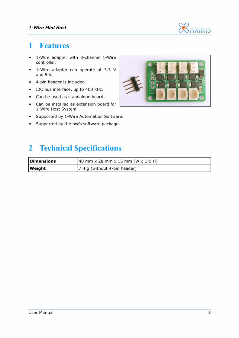
1 Features▪ 1-Wire adapter with 8-channel 1-Wire
controller.
▪ 1-Wire adapter can operate at 3.3 V and 5 V.
▪ 4-pin header is included.
▪ I2C bus interface, up to 400 kHz.
▪ Can be used as standalone board.
▪ Can be installed as extension board for 1-Wire Host System.
▪ Supported by 1-Wire Automation Software.
▪ Supported by the owfs software package.
2 Technical SpecificationsDimensions 40 mm x 28 mm x 15 mm (W x D x H)
Weight 7.4 g (without 4-pin header)
User Manual 3

1-Wire Mini Host
3 Installation
1-Wire Host System Extension
The 1-Wire Mini Host fits as an extension on the 1-Wire Host System. It adds another eight 1-Wire channels to the four channels that are already present on the 1-Wire Host System.
Follow these steps to install the extension board:
1. Solder the 4-pin header as shown in the left picture.
2. Plug the 1-Wire Mini Host in connector K7 of the 1-Wire Host System. Drive screws through the mounting holes to secure the board. Connector K7 is located in the extension area as indicated in the right picture.
As an extension board, the 1-Wire Mini Host operates at 5 V. It resides on the same I2C bus as the on-board 1-Wire controllers and I/O expander chip.
StandaloneYou can use the 1-Wire Mini Host as a standalone board in your project. In this capacity, you can solder the 4-pin header as you wish, thus facing upwards or downwards, or you can opt to solder another means of connection.
4 User Manual

1-Wire Mini Host
4 1-Wire Mini Host
Board Overview
Label Description
K1 DS2482-800 1-Wire controller channel 1
K2 DS2482-800 1-Wire controller channel 2
K3 DS2482-800 1-Wire controller channel 3
K4 DS2482-800 1-Wire controller channel 4
K5 DS2482-800 1-Wire controller channel 5
K6 DS2482-800 1-Wire controller channel 6
K7 DS2482-800 1-Wire controller channel 7
K8 DS2482-800 1-Wire controller channel 8
K9 Connector for I2C master
User Manual 5

1-Wire Mini Host
1-Wire Connector (K1-K8)
Mark Description
1 Vcc output
2 DQ
3 GND
This connector exposes a 1-Wire channel.
Connector for I2C Master (K9)
Mark Description
1 Vcc input
2 GND
3 I2C serial data (SDA)
4 I2C serial clock (SCL)
Connection to the DS2482-800 1-Wire controller.
The controller can operate at 3.3 V and 5 V.
The slave address is 0011100b.
The chip supports a maximum bus speed of 400 kHz.
6 User Manual
1
2
3
12
43

1-Wire Mini Host
5 Software
1-Wire Automation SoftwareThe 1-Wire Mini Host can be used with the 1-Wire Automation Software. Client command Adapter Add can be used in various ways.
adapter "ow" add i2cdev "/dev/i2c-2" ds2482 1ChThe adapter is connected to the I2C bus with device path /dev/i2c-2.
adapter "ow" add serial "\\.\COM5" axicat twi ds2482 1ChThe adapter is connected to the I2C bus of an AxiCat plugged into a Windows PC.
The image above shows the 1-Wire Automation Server GUI displaying the 1-Wire Mini Host with a MAX31850 thermocouple chip connected to the fourth channel.
In the free version of the server, enumeration is limited to the first channel of the first controller. The connector of this channel is labeled “K1” on the 1-Wire Mini Host. The orange marker in the image to the left shows the physical location of the channel's connector.
User Manual 7
1-Wire Mini Host
owfsThe 1-Wire Mini Host can be used with owfs, the 1-Wire File System. This software package is available from the following website:
http://www.owfs.org/
The owfs software includes programs that expose the 1-Wire hardware in a variety of ways to the system:
▪ owfs: Creates a file system in a specified mount directory. This program requires software package libfuse.
▪ owhttpd: Sets up a web server.
▪ owftpd: Sets up an FTP server.
▪ owserver: A server that allows multiple client programs to access the 1-Wire hardware.
These programs support a uniform command line syntax for specifying which 1-Wire adapters to detect and to expose. For the 1-Wire Mini Host, the --i2c command line option is of importance.
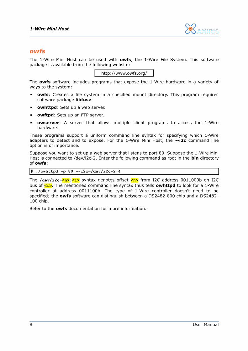
Suppose you want to set up a web server that listens to port 80. Suppose the 1-Wire Mini Host is connected to /dev/i2c-2. Enter the following command as root in the bin directory of owfs:
# ./owhttpd -p 80 --i2c=/dev/i2c-2:4The /dev/i2c-<n>:<i> syntax denotes offset <n> from I2C address 0011000b on I2C bus of <i>. The mentioned command line syntax thus tells owhttpd to look for a 1-Wire controller at address 0011100b. The type of 1-Wire controller doesn't need to be specified; the owfs software can distinguish between a DS2482-800 chip and a DS2482-100 chip.
Refer to the owfs documentation for more information.
8 User Manual

1-Wire Mini Host
6 ESD/Lightning ProtectionWhen you're planning to expose your 1-Wire network to the open air or an hostile environment, ESD and nearby lightning strikes may hit your 1-Wire network and destroy the 1-Wire Mini Host and 1-Wire slaves in the process.
We strongly advice to protect your 1-Wire Mini Host if such problems are real. Here's an example circuit to protect a 1-Wire adapter. Note that for the correct functioning of the circuit, a reliable earth connection is required (computer chassis, mains earth connector, grounding pin, …).
You can opt to protect 1-Wire slaves as well. Here's an example circuit to protect a 1-Wire slave from certain destructive discharges on the 1-Wire network:
The diagrams presented here are example circuits. It's the end-user's responsibility to provide the required protection measures to prevent the 1-Wire Mini Host from being destroyed by electrical discharges and similar phenomenons.
User Manual 9
1N
5404
1N
5404
1N
5404
22R
22R1.5
KE10ACCT
10V 1
500W
DQ
GND
DQ
GND
1-Wire Adapter
1-Wire Network
PE
1N
4004
12V 1W
47RDQ
GND
DQ
GND
1-Wire Slave
1-Wire Network
1N4004

1-Wire Mini Host
7 Legal Information
DisclaimerAxiris products are not designed, authorized or warranted to be suitable for use in space, nautical, space, military, medical, life-critical or safety-critical devices or equipment.
Axiris products are not designed, authorized or warranted to be suitable for use in applications where failure or malfunction of an Axiris product can result in personal injury, death, property damage or environmental damage.
Axiris accepts no liability for inclusion or use of Axiris products in such applications and such inclusion or use is at the customer's own risk. Should the customer use Axiris products for such application, the customer shall indemnify and hold Axiris harmless against all claims and damages.
Trademarks“Maxim Integrated” is a trademark of Maxim Integrated Products, Inc.
“1-Wire” and “iButton” are registered trademarks of Maxim Integrated Products, Inc.
All product names, brands, and trademarks mentioned in this document are the property of their respective owners.
8 Contact InformationOfficial website: http://www.axiris.eu/
10 User Manual