1 welded mini-tube ecoilomica/ly sn/ves multi-faceted ... · the awal'd winner ld/l...
TRANSCRIPT

1 Welded Mini-Tube ECOIlOmica/ly Sn/ves Multi-Faceted Problems 8
2 "Trussed T/lbe" /01' Landmark Building 9
9 1976 Prize Rrid.'lcs 12
MODERII COIiSTRUCnOIi Publ ished by
American Institute of Steel Construction 1221 Avenue of the Americas New York, N.Y. 10020
0 ..... C.R9
David B. Hughes, President George W. Hall, First Vice President Robert P. Stupp,
Second Vice President William J. Tilley, Jr., Treasurer John K. Edmonds,
Executive Vice President Leslie H. Gillette,
Assistant Executive Vice President William W. Lanigan,
Secretary and General Counsel
EDITORIAL STAFF
Daniel Farb, Director of Publications Mary Anne Stockwell, Editor
REOIONAL 0 .... IC.9
Atlanta. Georgia Birmingham, Alabama Boston, Massachusetts Chicago, Illinois Cleveland, Ohio Columbus, Ohio Dallas, Texas Denver, Colorado Detroit, Michigan Charlotte, North Carolina Houston, Texas Kansas City, Missouri Los Angeles, California Memphis, Tennessee Minneapolis, Minnesota New York, New York Philadelphia, Pennsylvania Pittsburgh, Pennsylvania St. Louis, Missouri San Francisco, California Seattle, Washington Syracuse, New York Washington, District of Columbia
VOLUME XVI I NUMBERS 3 & 4 I THIRD & FOURTH QUARTER 1976
CONTENTS
"Trussed Tube" for Landmark Building
Welded Mini-Tube Economically Solves Multi-Faceted Problems
1976 Prize Bridges
Practical Steel Design for Buildings 2-20 Stories
NEW LECTURE SERIES
3
8
12
16
AISC is conducting a new lecture series On "Pmctical Steel Design fOl' Bllildings '2-20 Stol'ies." Lectures are now being schedllied in cities throllghollt the United States. For l1tOl'e inlonnation, see olltside back cover of this issue of Modent Steel Conslrllction.
THE SEVENTH ANNUAL T . R. HIGGINS LECTURESHIP AWARD
The T, R. Higgins Lectll1'eship Award Program will select the principal allthor of the technical paper judged to have made the most significant contriblltion to engineering literatllre l'elated to laMicated st1'1lctl1ral steel within a five yeal' eligibility period ending Jallllary I, 1976. The awal'd winner ld/l l'eceive a $2,000 prize during a caemony at the 1977 AISC National Engineering Conlerence in Washington, D.C., where he will present his papel ..
A j111'Y of .~i:r eminent engineel's from the fields of education , design, and indllsl1'y will select the awal'd winner. They are:
UOllel F, Currier Louisville & Nashville Railroad Company Wallace W, Sanders, Jr, Iowa State University A, C. Van Tn.sel Pittsbw'gh-Des Moines Steel CO'ntpany it-rlfl M. Vies' Bethlehem Steel COl'poration Corlleli, .. Wallrlmacl,er University 01 Cincinnati Ol/",r Z"lrI".,,,,,i Zaldastani Associates Inc.
1977 FELLOWSHIP AWARDS PROGRAM
FOllr $3, ,500 a!ca)'ds will be gmnted to Master's degree candidates pw'slling a cOlll'se of study )'elated to fabricated stnlcIIll'al steel. $3,000 is for the student's lise, and $500 is fo)' the department chairman's use in administering the gmnt,
St IIdents interested should contact their department chairmen or the Committee on Education, AISC, 1221 Avenue of the Americas, New York, N.Y. 10020.
•
•
•

THIRD/FOURTH QUARTER 1976
"Trussed Tube" for Landmark Building
Dallas' tallest building, the landmark 56-story First International office tower. Incorporates a wind bracing and floor framing system that led to substantial savings in the amount of structural steel required for construction_
Located in the Southwest's largest financial complex on a 2.5·acre parcel, the building reaches 710 It above street level. Totalling 1.9-million sq ft of space, the entire complex includes the office tower, a drive-up banking fa cility, and an II -story detached parking garage accommodating 1,000 vehicles_ Underground tunnels link the project with nearby buildings comprising the city's financial district. The building also features tandem elevators (two cabs per shaft) to handle vert ical passenger movement more efficiently during peak traffic periods_
Structural Concept Use of a "trussed tube" system at
the perimeter of the building to resist lateral wind forces and some gravity loads eliminated the need for wind bracing wilhin Ihe building_ Core columns could be designed for gravity only and a column-free Interior span of 40 fl from core to exterior columns was produced, thus reducing overall steel requirements. A built-up stub girder system reduced floor-Io-floor height in the building and provided additional economies in materials for the curtain wall system. Both systems produced savings of $1.50 per sq ft.
3

Tlte highill "i.ible .,y·bracing i, ,un from both ~:rt~TioT and int
4
South l'/r1.'atio" .hOft'i"U location o/night lighting
StnLctural cOllcrpt
MOOERN STEEL CONSTRUCTION
•
•
•

• Trussed Tube Wind Bracing System The "trussed tube" design is in the
form of diagonal X-bracing. Each X spans 28 floors, with two braces on each side of the building. This system is particularly efficient in resisting wind load in that the faces of the "tube" perpendicular to the wind direction also participate in resisting the wind load. In effect, the trussed tube acts as a solid tube cantilevered out of the foundations except for the "shear lag" effect. On the interior, diagonal braces of the X appear in perimeter offices as slanting columns, providing an altractive and interesting design feature_
There were several items of architectural /s tructural coordination associated with the trussed tube concept. Because the diagonals had to intersect columns at spandrel beams, a 12 fI-G in. floor-tofloor height was selected, along with a 25 fI-a in. column spacing. The design team decided to locate the vertical bracing within the curtain wall to avoid both problems associated with fireproofing the exterior structure and problems with temperature effects on the exposed steel. Another architectural ramification is that interior column flexibility permits efficient planning of the core and interior office space.
The components of the exterior framing - beams, columns, and diagonals - were fabricated from highstrength W14 shapes, except for a few near the boltom which were built-up shapes. The W14 shapes were selected because of the wide range of available sections and because all shapes had the same nominal inside dimension between flanges, thus facilitating the connection details_ Diagonals were fabricated four stories in length. Where diagonals intersect columns at every fourth floor, gusset assemblies were used to connect the diagonals, columns, and beams_ The gusset plate
Located in the heart 0/ the financial center, the First International offiec tower 18 Dalla.' talleat office building.
THIRD/FOURTH QUARTER 1976 5

IntffioT column flexibility permitted maximmn 'pace efficiency
.MU~ CC*,"E,,"caS
'4- SL"'II
~ , I .. ," S f["'1 t ~
."ULDteJ( fA HS~
.16 '''AClIII ....... '!-
... C Ito!:It I I I
Mi.celianeo1t. detail.
6
<t, - ...
I T ...
connections were fabricated from two • plates, each up to six inches thick, of high-strength steel. The diagonals were field welded at one end to reduce gusset and splice plate material and highstrength bolted through splice plates at the other end to provide necessary toler-ances for erection.
Corner gusset assemblies were required where diagonal bracing met at the corners of the building (at the roof, mid-height, street, and basement levels)_ These corner gusset assemblies were fabricated from four plates, two in each of two directions. The four plates were joined by electroslag welds (full penetration) and were stress-relieved after fabrication. Elevation dimensions of the gusset assemblies were selected based on the number of bolts required and the bolt pattern. Gusset plate thicknesses were sized based on finite element analysis of the gusset assembl ies.
Stub-Girder Floor System The built-up girder is considered
functionally to be ana logous to a vierendeel truss. The bottom chord of the • vierendeel is the WI4 girder, the top chord is the metal deck/concrete slab, and the verticals of the analogous truss are the WI6 stub pieces. As in a vierendeel truss, the bottom and top chords (girder and floor slab) are designed for combined bending and axial load.
r
I •
I • ...
MODERN STEEL CONSTRUCTION

•
•
This floor system permits integration of the mechan ical system through the structural frame and assists in minimizing floor-to-floor height and in reducing floor framing weight (21.6 psf). The system consists of a high·strength W14 girder with intermittent W16 stub pieces welded on top of the girder. The girder and stub pieces act compositely with the 6V4-in. metal deck/lightweight concrete floor slab through headed stud shear connectors on top of the stub pieces. W16 floor beams are semi-continuous over the top of the girder.
Design Concept The office tower is clad in a glass
window wall, with the entire structural frame and diagonal bracing within the building. This permits a more constant temperature and minimizes thermal expansion of the frame. It also simplified the detailing of the exterior skin.
The generating design idea of the office structure was to recognize the varying moods and sensitivities of the day· light and nighttime hours in a reflective glass concept. During the day the building is a monolithic reflective glass tower and mirrors its external environment. In the evening hours, the character changes as interior lighting permits views into the lower parts of the building, and as the structural concept is revealed by a lighting system applied to the tube members, making the tower visible for miles in all di rections.
• • • • • '-"l •
• ., • - • ... - .... - I • -.-. • - I • • •
oc I • •
e· I • • • • • • •
Typical Floor Plan ... • m J9th-32nd FloOT. ~~ -.;;
THIRD/FOURTH QUARTER 1976
Arch itects: Hellmuth, Obata & Kassabaum, Inc., St. LOUIS, Mo. Harwood K. Smith and Partners, Inc., Dallas, Texas
Structura l Engineer: Ellisor & Tanner, tnc., Dallas, Texas
General Contractor: Henry C. Beck Company, Dallas, Texas
Steel Fabricator: Mosher Steel Company. Dallas, Texas
7

VVelded Mini-Tube Economical
•
,.. ~ .. •
8
by Horatio Allison and Michael S. McCormac Partners, Horatio Allison- Robert L. Meyer Structural Engineers Rockville, Md.
11 .
A variation on the tubular design concept, most often used in very tall buildings, can be seen in the 23-story Town Center Office Building, Rockville, Maryland. This "mini-tube" system, in combination with practical welding techniques, resu lted in an economical, modern, innovative design that met the requirements of the owner.
The IOI-ft square building is flanked on each side by three parking levels
MODERN STEEL CONSTRUCTION
•

, )
•
----------
olves Multi-Faceted Problems with 62 ft-O in. clear spans and a plaza level. The framed areas of the parking and plaza levels, typical floors, and roof total 337,700 sq ft.
To conserve headroom, a floor-framing system of lightweight 3%-in. concrete slab with 1'12-in. composite metal deck on composite beams and girders was selected. The exterior spandrel beams and columns carry the lateral loads by "mini·tube" action.
THIRD/ FOU RTH QUARTER 1976
Design Problems Meeting the owner's requirement -
producing a building that would satisfy maximum occupancy and/or wind loads most economically - presented several design problems.
As in many instances, a zoning code height restriction problem required a very low story-to-story dimension of 10 ft-4 in. for a 23'story structure. The contractor for the project helped in prepar-
ing comprehensive cost analyses for various structural schemes that would meet this requirement.
The mechanical engineer determined that, for a steel framing system, 1 ft-2 in. ± was needed from the bottom of construction to the ceiling line for the most part, but that 1 ft-6 in. was required in other instances. The solution was to use 8-in. maximum depth composite floor beams and girders, except
9

Arch itect: James Cosgrove Associates Rockville, Maryland
Structural E"Bineer: Horatio Allison - Robert L. Meyer Rockville. Maryland
General Contractor: Robert Whalen Construction Corp. Rockville, Maryland
in the core area, where 4-in., 5-in., and 6-in. beams were used to allow more clearance for larger air ducts.
Three Schemes Considered From the contractor's estimates, it
became apparent that a steel framed building would be most economical, provided an inexpensive way could be found to resist the lateral forces. Three different schemes for wind load design were considered.
First, for a 23-story building, it would not be unusual to expect to find a moment resisting welded frame. However, the extremely low story heights make such a solution impossible since the 8-in. maximum girder depth would not provide adequate stiffness.
The scheme which did prove to be the solution was to increase t~e number of columns on the exterior walls by adding columns at mid-bay to achieve an 11 ft-O in. uniform column spacing. By using these closely spaced columns with stiff floor beams, a rather stiff frame was created. If all sides of the bu i lding are considered to act together as a single unit, the action can be described as being similar to that of a tube with openings in the walls. For this project, the use of a complete tube analysis proved unnecessary. In effect, only part of the tube was used, that is, the tube walls parallel to the direction of the wind load. Thus, the phrase "mini-tube" was coined for the design concept. This design proved to be a stiff and economical solution, except for one problem.
•
Next considered was the vertical cantilever truss. This method also proved to be impractical. However, in the perpendicular direction, the maximum obtainable depth for the cantilever truss is about 8 It-O in., or a depth-to-span ratio of about 28.
At the plaza level and at the parking levels, it was necessary to eliminate • columns to provide an open main entrance for the bank at the plaza level
Bolt moml'nt conn('etion
~ w • , ~
_ ~n c WleA40 ...
i:C*H ro-
r ,~,
I I .Q
;/'1 ...
. '" 10 ~- -~'
Nl,
10
... e ,,40
vo~ CAP>. G&.4. Z4f2. 36..0"
T_ C' I~".e/ ~ .. 910(
TRY 4~ "'e'~ A·49C e.OLT!t
TENS -.E. CA9o. 3~ At"" bO'... T
TFtY WT 10 III 7'
t( •. 09'- l ..... . 6~8
'cI • '''49
_ ,/, •• _(i~1 2 • t H
,~ ~ ..... ,DE. A5~£M& .. Y '11.9,1/;/ •• ~ 71</
TOTAL. &Q..... ~OA.O .. 9l~". 7..e. ...
• 22 7~·7;& 'Z!J'!o"c52.41 01(
""1 '7.'&112" '4.M· 14. !Ii
f· ("-2,,')( 09!!t)1' 7."1(~ 0..;
•
and driveways at the parking levels.
Partial/raming plan
~ x
x I
r
x I
• H
I
'" rhul ___ 3... tl'lllIomU/'fl Ittr'l wtIQtII C(ln(:r.te o..r "'".(1; CI"'~ • • tfnfQl'CIoCI wr.,tf'.6, .lQ/alQwWF
~
H H
~ • ~. ~ •
'C'
..
:... '4'8 _28 l52 5~ L!lj 'Il' - --'--
Fy • 50 = m
I ~ ':: m
m • • •• *8. <48 .!'O] r.,..<45
r ~
I ~ ~ • .~ ~.
'" = - 'N' -"", m
~ N
I ~ ; · m • •
do x W'h '5 '4'12 • ..:!.. X~
I I
1 ~ H H-
~ ....- ~
w •• , H H-
'C' 41 t. I ~ .. i ~ ~ ~
«)~ .. * ~~ I "'. - . .-;~~. .;;"" t 'C: CI ~LN
WIO~_5 2l0(II'I ""'. r-·+"· .. ·, ~f15
•
MODERN STEEL CONSTRUCTION
•
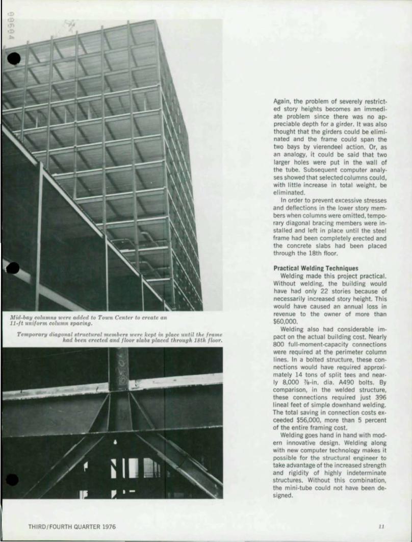
Mid-baJl colunI". "'crt' added to Town Center to CT('at~ an ll-ft uniform column .pacing.
TemporarJl dial1onalatruc:tural mt"mbcr, v'rrf' kcpt in plact until thf' frame had bern erected and floor .lab. placed thrOllUh 18th floor.
THIRD / FOURTH QUARTER 1976
Again, the problem of severely restricted story heights becomes an immediate problem since there was no appreciable depth for a girder. It was also thought that the girders could be eliminated and the frame could span the two bays by vierendeel action. Or, as an analogy, it could be said that two larger holes were put in the wall of the tube. Subsequent computer analyses showed that selected columns could, with little increase in total weight, be eliminated.
I n order to prevent excessive stresses and deflections in the lower story members when columns were omitted, temporary diagonal bracing members were installed and left in place until the steel frame had been completely erected and the concrete slabs had been placed through the 18th floor.
Practical Weld ing Techn iques Welding made this project practical.
Without welding, the building would have had only 22 stories because of necessarily increased story height. This would have caused an annual loss in revenue to the owner of more than $60,000.
Welding also had considerable impact on the actual building cost. Nearly 800 full-moment-capacity connections were required at the perimeter column lines. In a bolted structure, these connections would have required approxi mately 14 tons of split tees and nearly 8,000 "¥e-in. dia. A490 bolts. By comparison, in the welded structure, these connections required just 396 lineal feet of simple downhand welding. The total saving in connection costs exceeded $56,000, more than 5 percent of the entire framing cost.
Welding goes hand in hand with modern innovative design. Welding along with new computer technology makes it possible for the structural engineer to take advantage of the increased strength and rigidity of highly indeterminate structures. Without this combination, the mini-tUbe could not have been designed.
II

1976 PRIZE
BRIDGES
PRIZE BRIDGE 1976 - MEDIUM SPAN , HIGH CLEARANCE ... White Bird Canyon Bridge White Bird, Id DU l l ner/ Owner. Idaho Transportation Department, Division of Hlihways Gener,l Contractor : Hensel Phelps Construction Company Fabncator: Allied Structural Steel Company Erector: Fought & Company. Division of Allied Equities Corp.
PRIZE BRIDGE 1976 - MEDIUM SPAN, lOW CLEARANCE ... Clarno Bridge over the John Day RIVer Southeast of 'the Oalies, Ore Desilner: Bridge Section, State Highway Division,
Oregon Department of Transportation Owner: Oregon Department of Transportation General Contracto r: Hensel Phelps Constructio" Company Fabricator/ Erector: Fought & Company. Division of Allied Equities Corp.
12
PRIZE BRIDGE 1976 - LONG SPAN Marquette - Prairie du Chien - West Channel Bridge Across t he MississippI River between Marquette, 18. and Prairie du Chien, Wis. Designer: Slate of Wisconsin, Division of Highways Owners: Slate of Wisconsin and State of Iowa General Contractors: Allied Structural Steel Company and INRVCO, Inc.
CA Joint Venture) Fabricato rs: Allied Structural Steel Company and INRVCO, Inc.
CA JOlOt Venture) Erector: Industrial Construction Division, Allied Structural Steel Company
PRIZE BRIDGE 1976 - MEDIUM SPAN, HIGH CLEARANCE .A. Brady's RUn Park Bridge Brighton Township, Pa . Desi l ner: Michael Baker, Jr., Inc. Owner: Commonwealth of Pennsylvania, Department of Transportation Gene ral Contra cto r: W. P. Dickerson and Son, Inc. Fabricalor: Fort Pitt Division of Spana Industries, Inc. Erector: American Bridge Division, UMlted States Steel
PRIZE BRIDGE 1976 - SHORT SPAN Mounts Bay Road Br. idge over Halfway Creek James City County, Va Des ianer: Fraioli-Blum-Vesselman Associates, Inc. Own er: Busch Properties, Inc., a subsidiary of Anheuser-Busch, Inc. General Contractor: Sanford Construction Company Fabricator/ Erector: Globe I ron Construction Co.
PRIZE BRIDGE 1976 - GRADE SEPARATION Burlington Northern Railway over Beam Avenue Maplewood , Minn. Desianer: Howard Need les Tammen & Bereendoff Owner: City of Maplewood General Contractor: l unda Construction Company Fabricator: PhoeMlx Steel Corporation Erector: lunda Construction Company
MODERN STEEL CONSTR UCTION
•

•
PRIZE BRIDGE 1916 - ElEVATED HIGHWAYS OR VIADUCTS Bigley Interchange Charleston, W. Va. Desi,ner: Howard Needles Tammen & _Bergendoff Owner: West Virginia Department of Highways Gener.' Contractor: Allied Structural Steel Company Fabricator: Allied Struct ural Steel Company Erector: Industria' Construction Division,
Allied Structural Steel Company
.... PRIZE BRIDGE 1971 _ SPECIAL PURPOSE Moore's Run Pedestrian Bridge Baltimore City, Md Dui,ner: MCA Enfineerina Corporation Owner: City of Ba lImor. General Contractor: Interstate Bridge Company of Maryland, Inc. Fabrlc. tor: AtI.s Machin. & Iron Works, Inc. Erector: Interstate Bridae Company of Maryland, Inc.
.... AWARD OF MER'T 1976 - MEDIUM SPAN , HIGH CLEARANCE New Emsworth Bridge Emsworth Borouah, Pa . DUllner: Michael Baker, Jr., Inc. Owner: Port Authority of Allegheny County General Contractor: Gerace Const ruction Corp. Fabrlc.tor/ Erector: American Brldae DI'"ision, United State, Steel
TH IRD/ FOURTH QUARTER 1976
PRIZE BRIDGE 1976 - MDVABLE SPAN Back Bay Bridge BlloKl, MISS, DU llner: Hazellt & Erdal Own er: MiSSiSSip,Pi State Hilhway Department General Contr.c or: Michael Con!!.tructton ComJ)llny of MissiSSippi, Inc. Fabricator: Tucker Steel, Inc. Erector: Michael Construction Company of Mississippi, Inc.
AWARD OF MERIT 1976 - LONG SPAN 1-24 Bridge over Tennessee River Marshall and liviniston Counttes, Ky. Desi,ne rs: Kroboth Eneineers, Inc. and S."erdrup& Parcel and Associates, Inc.
(A Joint venturek Owner: Commonwealth of entucky, Department of Transport.tion Gener.' Contrll ctor: Allied Structur.1 Sleel Company Fl bflcator/ Erector: Allied Structural Steel Company
AWARD OF MERIT 1976 - MEDIUM SPAN, HIGH CLEARANCE Harry S, Truman Oam and Reservoir, St. Clair Countl Brid.e No. SC·36 State Route C, S . CI.lfl..:ounty, Mo Desll ner: . U.S. Army Corps of Enaineers, Kansas City District Owner: MISSOUfi State Highway CommiSSion Genera l Contractor: Ted Wilkerson, Inc. f abricator: Kansas City Structurl' Steel Company [rec tor. Ted Wilkerson, Inc.
13

AWARD OF MERIT 1976 - MEDIUM SPAN, LOW CLEARANCE Pine Creek·Waterv i lle Bridge Lycom lna: County, Pa. Ouilner: Tyo and Fleisher, Inc. Owner: Commonwealth of Pennsylvania, Department of Transportation General Contractor: Reed & Kuhn Inc. Fabric.tor/ Erect or: Williamsport Fabricators, Inc.
AWARD OF MERIT 1976 - GRADE SEPARATION Grand Forks AFB Interchange Grand Forks, N O. Dnilner: Bridge Division, North Dakota State Hi&hway Department Owner: State of North Dakota General Contractor: Nort hern Improvement Company Fabricator: Egger Steel Company Erector: SWln&en ConstructIon Company
AWARD OF MERIT 1976 - GAADE SEPARATION Shrine Pass Interchange Summit County, Colo. Dui,ner: Meheen Enaineerina Co. ArchItectural Consultant: Cha rles Montoot~l . AlA,
The Frank Lloyd WII&ht Foundation Owner: Colorado Division of Highways General Contractor: H·E Lowdermilk Co. Fabllcator: The MIdwest Steel & Iron WOrks Co. Erector: Kenney Construction Co., Inc.
~ AWARD OF MERIT 1976 - MEDIUM SPAN , HIGH CLEARANCE Peyton Bridge Jackson County, Ore . DU i, ner: Federal Highway Admin istration, Offtce. of Western Bridae Desian Owner: U.S. Army Corps of Enameers, Portland Ol stllet General Contratlor: Hensel Phelps Construchon Company • Fabricator/ Erector: Fought & Company, DiviSion of All ied Equ ities Corp.
AWARD OF MERIT 1976 - MEDIUM SPAN, LOW CLEARANCE Dirty Devil River Bridge State Route 24, near Hanksville, Utah Desi,ner: Structures DiviSion, Utah Department of Tl'1Insportation Owner: Utah Department of ,ansportatlon General Contractor: l. A. Young Sons Const ruction Company Fabricator / Erector: Western Steel Company, Inc.
AWARD OF. MERIT 1976 - SHORT SPAN Byers Carion Bridsr:e uS 40, West of Hot Sulphur Springs, Colo. Desilner: Staff Brid.e Desig':'l . Colorado Division of Highways Owner: Colorado DIvision of HIghways Genera l Conlractor: Flatiron Pavlna Company Fabricator: Western Steel Company, Inc. Erector: Flatiron Paving Company
• AWAAD OF MERIT 1976 - GRADE SEPARATION Sample Bridge Road Overpass at 1·81 Hampden TownshIp, Pa. Dni,ner: Modjeski and Masters Owner: Commonwealth of Pennsylvania , Department of Transportation General Contractor: Hempt 8ros . Inc. Fabricator/ Erector: Hi&h Steel Siructures, Inc.
•

n
AWARD Of MERIT 1976 - GRADE SEPARATION Blooming Rose Road over National Freeway Frlendsvlll •• Md . Oesilne r: Ewell, Bomhardt & Associates Owner: Mllryllllnd State Highway Administration Gen" . 1 Contt.ctor: S . J . Groves & Sons Company , . brin lor: CUmberland Bridee Company Erector: Aycock, Inc.
AWARD OF MERIT 1976 - MOVABLE SPAN Smith River Bridge No. 19S.{).D Neat Gardiner, Oregon Duirn er: Oreion Bridie Enaineering Co. Owner: Douf,as County General Con rlctor: Holst Construction Co. Fabricator: Northwest Steel Fabricators, Inc. Erecto r: McKenlle Steel Co.
A AWARD OF MERIT 1976 - SPECIAL PURPOSE Fairview~St. Mary's Skyway System Minneapol is, Minn. Des i,"'r: Setter. leach & li ndstrom, Inc. Owners: Fairview Hospital and St. Mary's Hospital Gene,. 1 Contractor: Acton Const ruction Com pany Fabricator: L. L. Lejeune Company Erector: Vickerman Construction Co.
AWARD OF MERIT 1976 - MOVABLE SPAN Stratford Avenue Bridee Bndeeport, Conn . Oeslanar: Hardesty & Hanover Owner: State of Connecticut , Department of Transportation General Contractor: C. W. Blakeslee & Sons Inc.
.... Fabrica tor/ Erector: Hams Structural Steel Co., Inc,
AWARD OF MERIT 1176 - SPECIAL PURPO SE Pedestrian Bridu Brooklyn, N Y Structu ra l En l lneen: Wiesenfeld & Leon Architects: Oallls, BrOdV & ASSQC,ates f Horowitz & Chun Owner: Long Island unl"' ersltYI The Brooklyn Center Gener. 1 Contractor: J . Baranel a & Sons Fabflc. tor: Pecker Iron WOrks , Inc. Erector: Atles Steel Erectors Co., Inc.
I~
AWARD OF MERIT 1978 - SPECIAL PURPOSE 42nd & Hillsdale Pedestr ian Overpass Omaha, Nebr, Desilner: DUrand ASSOCiates, Inc. Owner: City of Omaha General Contractor: Lueder Construction Company Fabricator: Drake·Wiliiams Steel, Inc. Erector: Lueder Construction Company

AMERICAN INSTITUTE OF STEEL CONSTRUCTION 1221 Avenue of the Americas New York, N. Y. 10020
---Address Correction Requested
BULK RAT[ US POSTAGE
PAlO
NEWYORK.NY Permit No 6662
Practical Steel Design for Buildings/2-20 Stories Six lectures conducted by American Institute of Steel Construction
If you are an engineer who is inter· ested in the design of buildings -residential, commercial, or industrial -these lectures will provide you with new tools for better and easier steel design. The focus of this series will be on those construction systems that experi· ence has proven to be most efficient and economical for buildings 2 to 20 stories high. The simplified design techniques presented - and an un· derstanding of the reasoning behind them - can reduce the time requi red for good design.
Each registrant will receive a semi· nar kit of design aids, including a new booklet containing design information
and in·depth design examples from these lectures. The primary author of this new booklet is Horatio Allison, a nationally recognized expert on build· ing design and construction. The rna· terials in these seminar kits will serve as a useful reference throughout the lectures and as a valuable aid in daily practice.
Lectures are now being scheduled in cities throughout the United States. For details about the program in your area, contact your local AISC regional engineer or write to AISC Lectures, 1221 Avenue of the Americas, New York. N.Y. 10020.
•
•
•