1 utrecht university, leuvenlaan 4, 3584 ce … clean systems, gilbert damping a ects the edge...
TRANSCRIPT
Bulk and edge spin transport in topological magnon insulators
Andreas Ruckriegel,1 Arne Brataas,2 and Rembert A. Duine1, 2, 3
1Institute for Theoretical Physics and Center for Extreme Matter and Emergent Phenomena,Utrecht University, Leuvenlaan 4, 3584 CE Utrecht, The Netherlands
2Center for Quantum Spintronics, Department of Physics,Norwegian University of Science and Technology, NO-7491 Trondheim, Norway
3Department of Applied Physics, Eindhoven University of Technology,P.O. Box 513, 5600 MB Eindhoven, The Netherlands
(Dated: November 3, 2017)
We investigate the spin transport properties of a topological magnon insulator, a magnetic in-sulator characterized by topologically nontrivial bulk magnon bands and protected magnon edgemodes located in the bulk band gaps. Employing the Landau-Lifshitz-Gilbert phenomenology, wecalculate the spin current driven through a normal metal|topological magnon insulator|normal metalheterostructure by a spin accumulation imbalance between the metals, with and without randomlattice defects. We show that bulk and edge transport are characterized by different length scales.This results in a characteristic system size where the magnon transport crosses over from beingbulk-dominated for small systems to edge-dominated for larger systems. These findings are genericand relevant for topological transport in systems of nonconserved bosons.
Introduction.− Topological insulators are electronicstates of matter where the bulk insulates and the edgeconducts. The edge modes are protected against weakperturbations and backscattering by the topology of thebulk band structure [1]. They are also chiral and propa-gate unidirectionally along the sample boundaries.
The notion of topologically protected edge states isnot unique to electronic systems. A growing number ofstudies investigates the possibility of topological magnoninsulators (TMIs) [2–23] as well as magnon Dirac [24–28] and Weyl semimetals [29–34]. Magnons are collec-tive excitations in magnetic systems in which the spinsprecess coherently around the direction of the local mag-netic order. As they allow one to transport spin withlow dissipation over long distances [35], magnon-baseddevices are promising for the growing field of spintron-ics [36]. In TMIs, the magnon band structure exhibits atopologically nontrivial energy gap that hosts protectededge states. These edge modes open a new channel forspin transport. Their robustness to perturbations as wellas their chiral nature makes them appealing from theperspective of applications. There is an important dif-ference between electronic and magnonic topological in-sulators arising from their difference in quantum statis-tics: While edge states in electronic systems are gap-less low-energy excitations, the edge modes in TMIs arehigh-energy states with a sizable gap. In ferromagnets,the edge modes therefore coexist with low-energy bulkmodes, and both will contribute to the spin transport[37].
While much effort has been devoted to identifyingpossible candidates for TMIs [2–4, 6–8, 10, 13, 14, 17–20, 22, 23], the transport properties of TMIs have re-ceived considerably less attention. Most studies so farfocus on the thermal Hall response of ideal TMIs, dis-regarding the ubiquitous sources of dissipation present
μ=0μ>0
l
Ibulk
edge
I
NM TMI NM
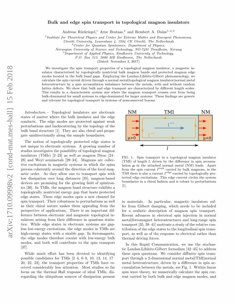
FIG. 1. Spin transport in a topological magnon insulator(TMI) of length l, driven by the difference in spin accumu-lation µ in the attached normal metal (NM) leads. Apartfrom the spin current Ibulk carried by bulk magnons, in theTMI there is also a current Iedge carried by topologically pro-tected edge excitations. This edge current circles the systemboundaries in a chiral fashion and is robust to perturbations[1].
in materials. In particular, magnetic insulators suf-fer from Gilbert damping, which needs to be includedfor a realistic description of magnon spin transport.Recent advances in electrical spin injection in normalmetal|ferromagnet heterostructures and long-range spintransport [35, 38–41] motivate a study of the relative con-tribution of the edge states to the longitudinal spin trans-port, as well as of the response to electrical rather thanthermal driving forces.
In this Rapid Communication, we use the stochas-tic Landau-Lifshitz-Gilbert formalism [42–45] to addressthese open questions. We consider diffusive spin trans-port through a 2-dimensional normal metal|TMI|normalmetal heterostructure, driven by a difference in spin ac-cumulation between the metals, see Fig. 1. Within linearspin wave theory, we numerically calculate the spin cur-rent carried by both bulk and edge magnon modes, and
arX
iv:1
710.
0999
8v2
[co
nd-m
at.m
es-h
all]
15
Feb
2018

2
(a) (b)
FIG. 2. (a) The honeycomb lattice structure, consisting of twointerpenetrating triangular sublattices with lattice constant a.The DMI changes sign depending on whether there is a rightor left turn between next-nearest neighbors. (b) A typicalmagnon edge state with frequency ω = 2.73 J in the bulk bandgap, obtained by diagonalizing the inverse magnon propagator(4) for vanishing damping and spin pumping (αi = 0 = µi)on a finite lattice with 930 lattice sites. Spin, magnetic fieldand DMI are fixed to S = 1, H = 0.1 J and D = 0.2 J in theplot.
find that they are described by two different spin diffu-sion lengths. We furthermore investigate the influenceof Gilbert damping, temperature and random lattice de-fects on the edge and bulk spin currents. Our findings arethat in a clean system the edge current is strongly sup-pressed by Gilbert damping and the large excitation gap.On the other hand, adding random defects strongly di-minishes the bulk current while having only a weak effecton the edge currents, reflecting the topological protectionof the edge states. For disordered systems we thus findthat the edge states dominate the spin transport for suf-ficiently large systems. While focusing on magnons, webelieve our results to be generic and to apply to physicalsituations where topological transport is carried by non-conserved bosons, such as e.g. certain photonic crystals[46–48].
Model and formalism.− We consider a TMI describedby the Hamiltonian
H =1
2
∑ij
[−JijSi·Sj+Dij z·(Si × Sj)
]−H
∑i
Szi , (1)
where the Si are spins of magnitude S localized at thesites Ri of a 2-dimensional honeycomb lattice in the x-yplane, see Fig. 2 (a). The exchange coupling is Jij =J > 0 for nearest neighbors, and Dij = −Dji = D > 0is the Dzyaloshinskii-Moriya interaction (DMI) betweennext-nearest neighbors. Lastly, H is the Zeeman energyassociated with an external magnetic field applied in thez direction that stabilizes the ferromagnetic ground state.In the ordered phase, the Hamiltonian (1) is known to bethe bosonic analog of the Haldane model [13, 49]. Whenthe DMI is finite, the system exhibits topologically non-trivial magnon bands and corresponding protected edgestates.
Spin dynamics are governed by the stochastic Landau-
Lifshitz-Gilbert equation (LLG):
∂tSi = Si ×[− ∂H∂Si
+ hi(t)−αiS∂tSi +
αspi
SSi × µi
](2)
where the Gilbert damping αi = α+αspi incorporates the
bulk Gilbert damping α as well as the interface Gilbertdamping enhancement αsp
i [50], and µi = µiz is the spinaccumulation in the left lead established, e.g., by the spinHall effect. Note that since both Gilbert damping en-hancement αsp
i and spin accumulation µi are only finiteon lattice sites connected to the leads, the correspondingspin-transfer torque terms in the LLG (2) are boundaryconditions. The stochastic magnetic field hi(t) modelsthermal fluctuations in the TMI and will be fixed by thefluctuation-dissipation theorem (FDT) in Eq. (5) below.
When H ≥ 0 and D < J/√
3, the bulk ground stateof the Hamiltonian (1) is the uniform state Si = Sz.Focusing on this case, we linearize in the deviationsmi = (Sxi + iSyi )/S from this uniform state to obtain themagnon equation of motion, which becomes in frequencyspace ∑
j
G−1ij (ω)mj(ω) = hi(ω). (3)
Here, hi(ω) is the Fourier transform of the circular com-ponent hi = hxi + ihyi of the stochastic field, and thematrix elements of the inverse magnon propagator aregiven by
G−1ij (ω) = δij
[− (1 + iαi)ω+H+S
∑n
Jin+iαspi µi
]+Tij ,
(4)with the complex hopping matrix elements Tij =−S(Jij + iDij). The magnon spectrum and eigenstatescan be obtained by diagonalizing the inverse propagator(4) in the absence of damping and spin pumping. A typ-ical magnon edge state with frequency in the bulk bandgap is displayed in Fig. 2 (b). Explicit calculations ofthe bulk band structure, Berry curvature, and associatedChern numbers are reviewed in the Supplemental Mate-rial [51].
At finite temperatures the magnon spectrum is pop-ulated by thermal fluctuations encoded in the stochas-tic magnetic field hi(ω). To ensure agreement with theequilibrium predicted by the quantum-mechanical linearspin-wave theory for magnons, we set 〈hi(ω)〉 = 0, and〈hi(ω)h∗j (ω
′)〉 = 2πδ(ω − ω′)Rij(ω), with a covariancematrix determined by the quantum-mechanical FDT [43–45, 53]:
Rij(ω) = δij4αi(ω − µi)/Se(ω−µi)/kBT − 1
. (5)
Finally, the total spin current I ejected into the rightlead in a stationary state can be obtained from ∂t〈Szi 〉 =

3
0 (see Supplemental Material [51] for details) and can bewritten as I =
∫dω2π I(ω), with
I(ω) =∑
i∈interface
Im[STG(ω)R(ω)G†(ω)
]ii, (6)
where the sum is over all lattice sites in contact with theright lead. By splitting the frequency integration intointegrals over the bulk bands and the bulk gap,
∫dω2π =∫
bulkdω2π +
∫gap
dω2π , we can separate the contributions from
the bulk bands and the edge states to the spin current,I = Ibulk + Iedge, and analyze them separately [54].
Numerical results and discussion.− In the following,we will present numerical results for the spin current Iejected into the right lead. We consider a finite 2 di-mensional honeycomb lattice with zigzag termination onthe sides attached to the leads and armchair terminationon the other two boundaries. The system has a variablelength l and a fixed width of 11 lattice sites that is largerthan the penetration width of the edge states. Only theoutermost lattice sites of the zigzag edges are connectedto the leads. The spin, applied field and DMI will befixed to S = 1, H = 0.1 J , and D = 0.2 J from hereon. For this set of parameters, the edge state gap pre-dicted by the bulk band structure is ∆ = 2.1 J . Gilbertdamping enhancement and spin accumulation are set toαspi = 1 and µi = 0.01 J respectively.
For the numerical solution, we have obtained themagnon propagator as a function of frequency by directinversion of Eq. (4). The bulk and edge spin currents,Ibulk and Iedge, are subsequently calculated by integrat-ing Eq. (6) over the respective frequency ranges. Tostudy the effect of lattice defects on the spin currents,a large on-site field is added to randomly chosen latticesites, effectively making them inaccessible to magnons.The lattice sites are chosen with a probability w and theresultant spin currents are averaged over many realiza-tions of defect distributions, so that the average defectconcentration is w. In practice, averaging over 25 defectrealizations is sufficient for convergence.
Figure 3 shows the dependence of the ejected spin cur-rent on the length l of the sample for different averagedefect concentrations w. For each w, the spin currentsdecays exponentially with increasing length l [55],
IX(l) ∝ exp(−l/λX
), X = bulk, edge, (7)
with respective spin diffusion lengths λbulk and λedge. Inthe clean limit, w = 0, the bulk contribution to the spincurrents decays far slower than the edge contribution, seeFig. 3 (a). This is expected because the only relaxationmechanism in this case is the Gilbert damping, which isproportional to the frequency of the magnon. As the edgestates are high-frequency states in the bulk band gap,they are affected far stronger by Gilbert damping thanthe low-frequency bulk magnons supporting the bulk spin
(a)
10 20 30 40 50 60
10-2
10-3
10-4
l / a
Spincurrent[J]
λbulk = 217.1 a
λedge = 64.6 a
(b)
10 20 30 40 50 60
10-3
10-4
l / a
Spincurrent[J]
λbulk = 16.2 a
λedge = 47.0 a
(c)
10 20 30 40 50 60
10-3
10-4
10-5
l / a
Spincurrent[J]
λbulk = 10.4 a
λedge = 32.4 a
(d)
10 20 30 40 50 60
10-3
10-4
10-5
10-6
l / a
Spincurrent[J]
λbulk = 9.8 a
λedge = 20.6 a
FIG. 3. Spin currents ejected at the right lead as a function ofthe system length l, for temperature T = 0.8 J , bulk Gilbertdamping α = 2.5× 10⁻³, and different average defect concen-trations w. Bulk and edge contributions are depicted as bluesquares and yellow circles respectively. The correspondingstraight lines are exponential fits according to Eq. (7), withthe spin diffusion lengths denoted in the plots. The defectconcentrations are (a) w = 0 (clean system), (b) w = 0.05,(c) w = 0.1, (d) w = 0.15. Deviations from the exponentialfit for l . 25 a signal the crossover to the thin-film regime inwhich the spin currents decay algebraically [35, 41].
current. At the same time, the total spin current car-ried by the edge magnons is 2 to 3 orders of magnitudesmaller than the bulk current, due to the exponential sup-pression of the high-frequency edge states by the thermalBose distribution in the FDT (5). However, as shown inFigs. 3 (b)-(d), adding defects has a dramatic effect onthis: while both bulk and edge diffusion lengths decrease,the effect on the bulk is far stronger, so that eventuallythe bulk contribution to the spin current decays, leavingonly the edge current. A discussion of the dependence ofthe spin diffusion lengths on the bulk Gilbert damping isrelegated to the Supplemental Material [51].
In Fig. 4 we plot the ratio of the edge to the bulkspin current injected into the TMI at the left lead as afunction of temperature. As anticipated, this ratio canbe fitted to an exponential [56]:
Iedgein (T )
Ibulkin (T )∝ J
kBTexp
(−ν J
kBT
), (8)
with a constant ν that is found to be close to 2 bothwith and without disorder. This reflects the exponen-tial suppression of the edge states by their excitation gap∆ = 2.1 J . The additional prefactor of 1/T stems fromthe bulk spin current which is dominated by the ther-mally populated low-frequency magnons. The ratio ofthe injected currents significantly increases by adding de-fects. This is caused by the weak localization of the bulkmagnon states induced by the disorder, which decreasesthe conductivity of the bulk and is a precursor to An-

4
0.0 0.2 0.4 0.6 0.8 1.0
0.00
0.01
0.02
0.03
0.04
0.05
0.06
0.07
kBT / J
I inedge/I inbulk
FIG. 4. Ratio of edge to bulk current injected at the left leadas a function of temperature T , for bulk Gilbert dampingα = 5× 10⁻³ and average defect concentrations w = 0 (greensquares) and w = 0.1 (red circles). The corresponding linesare fits with Eq. (8).
( a)
l*
l
Spincurrent
( b)
6 8 10 12 14
40
80
120
160
Defect concentration [%]
Crossingpoint[a]
log Ibulklog I
edge
log I
FIG. 5. (a) Schematic depiction of the contribution of edgeand bulk magnons to the total spin current, with the crossoverlength scale l∗. Note that l∗ →∞ for clean systems, see Fig. 3(a). (b) Numerically calculated crossing points l∗ (points) andthe order of magnitude estimate presented in the text (solidline). Parameters are the same as in Fig. 3.
derson localization [57, 58]. On the other hand, the edgestates are protected by the topology of the system andare only weakly affected by the random defects, comparealso Fig. 3.
Lastly, we give a simple order of magnitude estimateof the crossing length scale l∗ at which the edge cur-rent overtakes the bulk current, depicted schematically inFig. 5 (a). Assuming an exponential decay as in Eq. (7)
throughout, we have l∗ = ln(Ibulkin /Iedgein )/(1/λbulk −1/λedge). The injected currents may be estimated as
Ibulkin ∼ kBT/H and Iedgein ∼ exp(−∆/kBT ), where H isthe bottom of the bulk magnon spectrum; see Eq. (8) andthe subsequent discussion. The bulk spin diffusion lengthis dominated by the disorder, see Fig. 3, therefore we as-sume λbulk ∼ limp ∼ a/w, where limp is the mean freepath due to defect scattering. The spin diffusion length
of the edge magnons is estimated as λedge = v√
23τrτ
[41, 51]. Here, v = 2√JkBTa is the average magnon
velocity, τ−1r = 1/(2α∆) is the magnon relaxation ratedue to inelastic scattering, and the total magnon relax-ation rate is τ−1 = τ−1r + τ−1el and also includes elastic
scattering with defects and the sample boundaries takeninto account by τ−1el = limp/v. Although we ignore boththe thin-film regime and the effect of Gilbert dampingon the bulk spin current, Fig. 5 (b) shows a reasonableagreement of our estimate with the actual numerical re-sults, especially for higher defect concentrations wherethe aforementioned effects are less important.
Conclusions.− Edge states protected by topology area promising new tool for spintronics applications. Al-though the edge spin current is strongly suppressed bythe gap of the edge magnons, we have shown that ina disordered system the protected edge states dominatethe long-distance spin transport. While we have studieda particular model system, the honeycomb ferromagnet,we believe that our results are generic and pertain to allferromagnetic topological magnon insulators and, moregenerally, to topological boson systems. In particular,our theory should apply to the recently discovered topo-logical magnon insulator on a kagome lattice [7], as wellas to the proposed magnonic crystals with topologicallynontrivial magnon bands [3]. The honeycomb ferromag-net with Dzyaloshinskii-Moriya interaction that we inves-tigated may also be realized experimentally by deposit-ing magnetic impurities on a metal with strong spin-orbitcoupling [13, 59]. The latter two proposals have the ad-ditional advantage that the amount of disorder can beexperimentally controlled.
To directly connect to possible experiments, let us esti-mate the crossover length scale l∗ for two representativeexamples and moderate disorder concentrations w ∼ 0.1.For the kagome system Cu(1,3-bdc) investigated in [7],we find l∗ ∼ 0.1µm for T ∼ 1 K, H ∼ 1 T, and assum-ing α ∼ 10−2. This is roughly an order of magnitudelarger than the estimates we obtain for the spin diffusionlengths. We thus expect this system to be in the regimewhere bulk magnons dominate the spin transport. On theother hand, for the YIG|Fe magnonic crystal envisionedin [3], we estimate a crossover length scale l∗ ∼ 0.1µm atroom temperature, while the bulk spin diffusion length is∼ 1µm. Therefore spin currents carried mainly by edgemagnons should be readily observable in this system.
Future work should be focused on a more microscopicmodeling of the damping of the edge modes beyondthe Landau-Lifshitz-Gilbert paradigm. Especially at el-evated temperatures when the density of bulk magnonsis large, spin-wave interactions between bulk and edgemagnons may also change the transport properties ofboth drastically.
Acknowledgments.− RD acknowledges support as amember of the D-ITP consortium, a program of theNetherlands Organisation for Scientific Research (NWO)that is funded by the Dutch Ministry of Education, Cul-ture and Science (OCW). This work is in part fundedby the Stichting voor Fundamenteel Onderzoek der Ma-terie (FOM). This project has received funding fromthe European Research Council (ERC) under the Euro-

5
pean Union’s Horizon 2020 research and innovation pro-gramme (grant agreement 725509 - SPINBEYOND), andwas partially supported by the Research Council of Nor-way through its Centres of Excellence funding scheme,project number 262633, “QuSpin”.
[1] M. Z. Hasan and C. L. Kane, Rev. Mod. Phys. 82, 3045(2010).
[2] L. Zhang, J. Ren, J. S. Wang, and B. Li, Phys. Rev. B 87,144101 (2013).
[3] R. Shindou, R. Matsumoto, S. Murakami, and J. I. Ohe,Phys. Rev. B 87, 174427 (2013).
[4] R. Shindou, J. I. Ohe, R. Matsumoto, S. Murakami, andE. Saitoh, Phys. Rev. B 87, 174402 (2013).
[5] A. Mook, J. Henk, and I. Mertig, Phys. Rev. B 90, 024412(2014).
[6] X. Cao, K. Chen, and D. He, J. Phys.: Condens. Matter27, 166003 (2015).
[7] R. Chisnell, J. S. Helton, D. E. Freedman, D. K. Singh,R. I. Bewley, D. G. Nocera, and Y. S. Lee,Phys. Rev. Lett. 115, 147201 (2015).
[8] S. A. Owerre, J. Phys.: Condens. Matter 28, 386001(2016).
[9] S. A. Owerre, J. Appl. Phys. 120, 043903 (2016).[10] S. A. Owerre, Phys. Rev. B 94, 094405 (2016).[11] A. Mook, J. Henk, and I. Mertig, Phys. Rev. B 94,
174444 (2016).[12] B. Xu, T. Ohtsuki, and R. Shindou, Phys. Rev. B 94,
220403(R) (2016).[13] S. K. Kim, H. Ochoa, R. Zarzuela, and Y. Tserkovnyak,
Phys. Rev. Lett. 117, 227201 (2016).[14] S. A. Owerre, Phys. Rev. B 95, 014422 (2017).[15] X. S. Wang, Y. Su, and X. R. Wang, Phys. Rev. B 95,
014435 (2017).[16] P. Laurell and G. A. Fiete, Phys. Rev. Lett. 118, 177201
(2017).[17] S. A. Owerre, J. Phys.: Condens. Matter 29, 185801
(2017).[18] S. A. Owerre, J. Phys.: Condens. Matter 29, 385801
(2017).[19] S. A. Owerre, J. Appl. Phys. 121, 223904 (2017).[20] S. A. Owerre, Europhys. Lett. 117, 37006 (2017).[21] S. A. Owerre, J. Phys. Commun. 1, 021002 (2017).[22] K. Nakata, J. Klinovaja, and D. Loss, Phys. Rev. B 95,
125429 (2017).[23] K. Nakata, S. K. Kim, J. Klinovaja, and D. Loss,
Phys. Rev. B 96, 224414 (2017).[24] S. A. Owerre, J. Phys. Commun. 1, 025007 (2017).[25] N. Okuma, Phys. Rev. Lett. 119, 107205 (2017).[26] K. Li, C. Li, J. Hu, Y. Li, and C. Fang,
Phys. Rev. Lett. 119, 247202 (2017).[27] W. Yao, C. Li, L. Wang, S. Xue, Y. Dan, K. Iida, K. Ka-
mazawa, K. Li, C. Fang, and Y. Li, arXiv:1711.00632[cond-mat.mes-hall].
[28] S. Bao, J. Wang, W. Wang, Z. Cai, S. Li, Z. Ma, D. Wang,K. Ran, Z. Y. Dong, D. L. Abernathy, X. Wan, S. L. Yu,J. X. Li, and J. Wen, arXiv:1711.02960 [cond-mat.str-el].
[29] F. Y. Li, Y. D. Li, Y. B. Kim, L. Balents, Y. Yu, andG. Chen, Nat. Comm. 7, 12691 (2016).
[30] A. Mook, J. Henk, and I. Mertig, Phys. Rev. Lett. 117,
157204 (2016).[31] A. Mook, J. Henk, and I. Mertig, Phys. Rev. B 95,
014418 (2017).[32] Y. Su, X. S. Wang, and X. R. Wang, Phys. Rev. B 95,
224403 (2017).[33] Y. Su and X. R. Wang, Phys. Rev. B 96, 104437 (2017).[34] S. A. Owerre, arXiv:1708.04240 [cond-mat.str-el].[35] L. J. Cornelissen, J. Liu, R. A. Duine, and B. J. van
Wees, Nature Physics 11, 1022 (2015).[36] I. Zutic, J. Fabian, and S. Das Sarma,
Rev. Mod. Phys. 76, 323 (2004).[37] For this reason, the term topological magnon insulator
may by slightly misleading. While the system is an elec-tronic insulator, with respect to spin transport the bulk isactually conducting.
[38] S. B. T. Goennenwein, R. Schlitz, M. Pernpeintner,K. Ganzhorn, M. Althammer, R. Gross, and H. Huebl,Apll. Phys. Lett. 107, 172405 (2015).
[39] H. Wu, C. H. Wan, X. Zhang, Z. H. Yuan, Q. T. Zhang,J. Y. Qin, H. X. Wei, X. F. Han, and S. Zhang,Phys. Rev. B 93, 060403(R) (2016).
[40] J. Li, Y. Xu, M. Aldosary, C. Tang, Z. Lin, S. Zhang,R. Lake, and J. Shi, Nat. Commun. 7, 10858 (2016).
[41] L. J. Cornelissen, K. J. H. Peters, G. E. W. Bauer,R. A. Duine, and B. J. van Wees, Phys. Rev. B 94, 014412(2016).
[42] S. Hoffman, K. Sato, and Y. Tserkovnyak, Phys. Rev. B88, 064408 (2013).
[43] A. Brataas, H. Skarsvag, E. G. Tveten, and E. LøhaugenFjærbu, Phys. Rev. B 92, 180414 (2015).
[44] S. A. Bender, H. Skarsvag, A. Brataas, and R. A. Duine,Phys. Rev. Lett. 119, 056804 (2017).
[45] J. Zheng, S. Bender, J. Armaitis, R. E. Troncoso, andR. A. Duine, Phys. Rev. B 96, 174422 (2017).
[46] S. Raghu and F. D. M. Haldane, Phys. Rev. A 78, 033834(2008).
[47] Z. Wang, Y. Chong, J. D. Joannopoulos, and M. Soljacic,Nature (London) 461, 772 (2009).
[48] L. Lu, J. D. Joannopoulos, and M. Soljacic, Nat. Pho-tonics 8, 821 (2014).
[49] F. D. M. Haldane, Phys. Rev. Lett. 61, 1029 (1988).[50] Y. Tserkovnyak, A. Brataas, and G. E. W. Bauer,
Phys. Rev. Lett. 88, 117601, (2002).[51] See Supplemental Material, which includes Ref. [52],
for details on the bulk band structure, the derivation ofEq. (6) for the spin current, and the damping dependenceof the spin diffusion lengths.
[52] A. Ruckriegel and P. Kopietz, Phys. Rev. B 95, 104436(2017).
[53] In contrast to Refs. [43–45] we do not include zero-pointfluctuations in the FDT, because we are considering cir-cularly polarized ferromagnetic magnons. In this case thezero-point fluctuations do not contribute to the magneti-zation within linear spin-wave theory, and their effect onthe spin currents cancels as well [45].
[54] In principle the edge states are connected continuouslyto the bulk bands, so our separation is only approximate.However, since we consider a finite, mesoscopic system theenergy levels are discrete, with only a small broadeningdue to the Gilbert damping. We explicitly checked thatthere are no edge states with frequencies outside of theband gap, so that the separation of the spin current intobulk and edge currents is essentially exact.
[55] For very thin magnets, the decay actually becomes alge-

1
braic rather than exponential [35, 41]. We only considersystems large enough that the spin currents decay expo-nentially.
[56] The ratio (8) is independent of the width of the sam-ple because the edge modes are extended along the wholeboundary of the system, see Fig. 2 (b).
[57] M. Evers, C. A. Muller, and U. Nowak, Phys. Rev. B 92,014411 (2015).
[58] M. Evers, C. A. Muller, and U. Nowak, arXiv:1708.02807[cond-mat.mes-hall].
[59] J. Fransson, A. M. Black-Schaffer, and A. V. Balatsky,Phys. Rev. B 94, 075401 (2016).
SUPPLEMENTAL MATERIAL
Bulk bands, Berry curvature, and Chern numbers
In order to obtain the magnon band structure in a bulk system, we may neglect the effects of Gilbert damping aswell as spin pumping, and impose periodic boundary conditions, so that the magnon equation of motion (3) becomes
i∂tmi = (H + 3SJ)mi − S∑j
(Jij + iDij)mj . (S1)
Due to the periodic boundary conditions in the bulk, it is advantageous to Fourier transform to momentum space via
mi =
√2
N
∑k
eik·Ri ×
ak Ri ∈ Abk Ri ∈ B
, (S2)
where N is the total number of lattice sites, and A and B denote the two sublattices of the honeycomb lattice, seeFig. 2 (a). This turns the above Eq. (S1) into
i∂t
(akbk
)= [(H + 3SJ) I2 + hk · σ]
(akbk
), (S3)
where I2 is the 2 dimensional identity matrix, σ is the vector of Pauli matrices, and
hk = S
3∑i=1
−J cos (k · δi)J sin (k · δi)
2D sin (k · ρi)
. (S4)
Here the nearest neighbor vectors are defined as δ1 = (0,−a/√
3), δ2,3 = (±a/2, a/√
3), whereas the next-nearestneighbor vectors are ρ1 = (a, 0), ρ2,3 = (−a/2,±
√3a/2); compare Fig. 2 (a). From the equation of motion (S3) we
immediately obtain the dispersions of the two magnon branches,
ωk,± = H + 3SJ ± |hk|. (S5)
In the absence of DMI, the dispersions of the lower and upper magnon branches touch at the corners of the Brillouinzone, at the two Dirac points K ≡ (4π/3a, 0) and K ′ ≡ (2π/3a, 2π/
√3a). In the vicinity of these points, the magnon
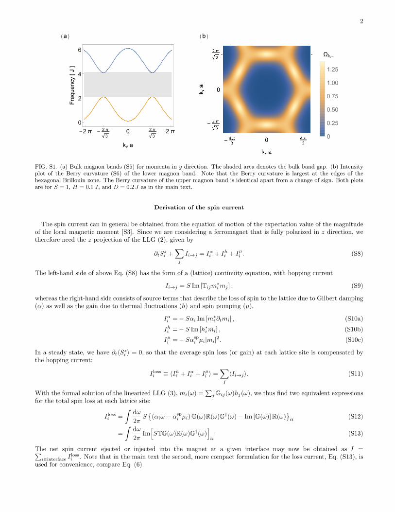
dispersions become linear [S1]. Finite DMI however lifts this degeneracy and opens a gap, thereby endowing themagnon bands with a nontrivial topology [S1, S2]. A plot of the two magnon bands with finite DMI is displayed inFig. S1 (a). The Berry curvatures of the magnon bands can be calculated from [S2]
Ωk,± = ∓ hk
2·
(∂hk
∂kx× ∂hk
∂ky
), (S6)
where hk = hk/|hk|. An intensity plot of the Berry curvature of the lower band is shown in Fig. S1 (b). The Chernnumbers associated with the nontrivial topology of the two bands are
C± =1
2π
∫BZ
d2kΩk,± = ∓1, (S7)
where the integral is over the first Brillouin zone.
2
(a)
-2π - 2π
30 2π
32π
0
2
4
6
ky a
Frequency
[J]
(b)
Ωk,-
0
0.25
0.50
0.75
1.00
1.25
FIG. S1. (a) Bulk magnon bands (S5) for momenta in y direction. The shaded area denotes the bulk band gap. (b) Intensityplot of the Berry curvature (S6) of the lower magnon band. Note that the Berry curvature is largest at the edges of thehexagonal Brillouin zone. The Berry curvature of the upper magnon band is identical apart from a change of sign. Both plotsare for S = 1, H = 0.1 J , and D = 0.2 J as in the main text.
Derivation of the spin current
The spin current can in general be obtained from the equation of motion of the expectation value of the magnitudeof the local magnetic moment [S3]. Since we are considering a ferromagnet that is fully polarized in z direction, wetherefore need the z projection of the LLG (2), given by
∂tSzi +
∑j
Ii→j = Iαi + Ihi + Iµi . (S8)
The left-hand side of above Eq. (S8) has the form of a (lattice) continuity equation, with hopping current
Ii→j = S Im [Tijm∗imj ] , (S9)
whereas the right-hand side consists of source terms that describe the loss of spin to the lattice due to Gilbert damping(α) as well as the gain due to thermal fluctuations (h) and spin pumping (µ),
Iαi =− Sαi Im [m∗i ∂tmi] , (S10a)
Ihi =− S Im [h∗imi] , (S10b)
Iµi =− Sαspi µi|mi|2. (S10c)
In a steady state, we have ∂t〈Szi 〉 = 0, so that the average spin loss (or gain) at each lattice site is compensated bythe hopping current:
I lossi ≡ 〈Ihi + Iαi + Iµi 〉 =∑j
〈Ii→j〉. (S11)
With the formal solution of the linearized LLG (3), mi(ω) =∑j Gij(ω)hj(ω), we thus find two equivalent expressions
for the total spin loss at each lattice site:
I lossi =
∫dω
2πS
(αiω − αspi µi)G(ω)R(ω)G†(ω)− Im [G(ω)]R(ω)
ii
(S12)
=
∫dω
2πIm[STG(ω)R(ω)G†(ω)
]ii. (S13)
The net spin current ejected or injected into the magnet at a given interface may now be obtained as I =∑i∈interface I
lossi . Note that in the main text the second, more compact formulation for the loss current, Eq. (S13), is
used for convenience, compare Eq. (6).

3
(a)
2 4 6 8 100
100
300
500
α [ 10-3 ]
Spindiffusionlength
[a]
(b)
2 4 6 8 100
15
30
45
60
α [ 10-3 ]
Spindiffusionlength
[a]
FIG. S2. Spin diffusion lengths as a function of the bulk Gilbert damping α, for temperature T = 0.3 J and average defectconcentrations (a) w = 0 and (b) w = 0.1. Bulk and edge spin diffusion length are depicted in blue (squares) and yellow(circles) respectively. The corresponding lines are fits with Eq. (S14). For the bulk spin diffusion length in (b) it was necessaryto add a small constant to the fitting function Eq. (S14).
Damping dependence of the spin diffusion lengths
In this section we investigate the dependence of the bulk and edge spin diffusion lengths introduced in Eq. (7)of the main text on the (bulk) Gilbert damping α. Fig. S2 shows the bulk and edge diffusion lengths as functionof the bulk Gilbert damping α for zero and finite defect concentrations w. Note that in the clean limit displayedin Fig. S2 (a), the edge current decays faster than the bulk current for all damping values considered. This is inagreement with the expectation that the high-frequency edge states are much more affected by the Gilbert dampingthan the low-frequency bulk magnons. On the other hand, as shown in Fig. S2 (b), a finite defect concentrationstrongly suppresses the bulk diffusion length but only weakly influences the edge diffusion length. Consequently, inthe presence of defects, the edge current decays slower than the bulk current for virtually all values of Gilbert dampingconsidered. In both cases, the damping dependence is fitted very well by
λX(α) =a√
γX1 α+ γX2 α2, X = bulk, edge, (S14)
with γX1 and γX2 constants. This may be understood phenomenologically by noting that the spin diffusion length in
ferromagnets is λ = v√
23τrτ [S4], where v is the average magnon velocity, τ−1r is the magnon relaxation rate due to
inelastic scattering, and the total magnon relaxation rate is τ−1 = τ−1r + τ−1el and also includes elastic scattering withdefects and the sample boundaries taken into account by τ−1el . As τ−1r ∝ α in ferromagnetic systems [S4], we obtaina spin diffusion length of the form of Eq. (S14) from this argument.
[S1] S. A. Owerre, J. Phys.: Condens. Matter 28, 386001 (2016).[S2] S. K. Kim, H. Ochoa, R. Zarzuela, and Y. Tserkovnyak, Phys. Rev. Lett. 117, 227201 (2016).[S3] A. Ruckriegel and P. Kopietz, Phys. Rev. B 95, 104436 (2017).[S4] L. J. Cornelissen, K. J. H. Peters, G. E. W. Bauer, R. A. Duine, and B. J. van Wees, Phys. Rev. B 94, 014412 (2016).