1. the basics 2. the components 3. features 4...
TRANSCRIPT

Product Description(4.0i)
4. Specifications and Parts List
2. The Components
3. Features
1. The Basics
This manual has been developed by NEC Unified Solutions, Inc. It is intended for the use of its customers andservice personnel, and should be read in its entirety before attempting to install or program the system. Anycomments or suggestions for improving this manual would be appreciated. Forward your remarks to:
NEC Unified Solutions, Inc.4 Forest Parkway
Shelton, CT 06484necunifiedsolutions.com
Nothing contained in this manual shall be deemed to be, and this manual does not constitute, a warranty of, orrepresentation with respect to, any of the equipment covered. This manual is subject to change without notice andNEC Unified Solutions, Inc. has no obligation to provide any updates or corrections to this manual. Further, NECUnified Solutions, Inc. also reserves the right, without prior notice, to make changes in equipment design orcomponents as it deems appropriate. No representation is made that this manual is complete or accurate in allrespects and NEC Unified Solutions, Inc. shall not be liable for any errors or omissions. In no event shall NEC UnifiedSolutions, Inc. be liable for any incidental or consequential damages in connection with the use of this manual. Thisdocument contains proprietary information that is protected by copyright. All rights are reserved. No part of thisdocument may be photocopied or reproduced without prior written consent of NEC Unified Solutions, Inc.
©2005 by NEC Unified Solutions, Inc. All Rights Reserved.Printed in U.S.A.
Table of Contents
Section 1: The Basics . . . . . . . . . . . . . . . . . . . . . . . . . . . . . . . . . . . . . . . . . . . . 1
Section 2: Components . . . . . . . . . . . . . . . . . . . . . . . . . . . . . . . . . . . . . . . . . . 5The Telephones. . . . . . . . . . . . . . . . . . . . . . . . . . . . . . . . . . . . . . . . . . . . . . . . . . . . 5Keyset Adapters . . . . . . . . . . . . . . . . . . . . . . . . . . . . . . . . . . . . . . . . . . . . . . . . . . . 9Optional Equipment . . . . . . . . . . . . . . . . . . . . . . . . . . . . . . . . . . . . . . . . . . . . . . . 12Aspire S Common Equipment . . . . . . . . . . . . . . . . . . . . . . . . . . . . . . . . . . . . . . . 16Aspire S Trunk PCBs . . . . . . . . . . . . . . . . . . . . . . . . . . . . . . . . . . . . . . . . . . . . . . 18Aspire S Station PCBs . . . . . . . . . . . . . . . . . . . . . . . . . . . . . . . . . . . . . . . . . . . . . 19Aspire (M/L and XL) Common Equipment . . . . . . . . . . . . . . . . . . . . . . . . . . . . . 27Aspire Trunk PCBs. . . . . . . . . . . . . . . . . . . . . . . . . . . . . . . . . . . . . . . . . . . . . . . . 33Aspire Station PCBs . . . . . . . . . . . . . . . . . . . . . . . . . . . . . . . . . . . . . . . . . . . . . . . 38Aspire Optional Feature Equipment . . . . . . . . . . . . . . . . . . . . . . . . . . . . . . . . . . . 43
Section 3: Features . . . . . . . . . . . . . . . . . . . . . . . . . . . . . . . . . . . . . . . . . . . . . 53Abbreviated Dialing . . . . . . . . . . . . . . . . . . . . . . . . . . . . . . . . . . . . . . . . . . . . . . . 53Account Codes . . . . . . . . . . . . . . . . . . . . . . . . . . . . . . . . . . . . . . . . . . . . . . . . . . . 54Alarm . . . . . . . . . . . . . . . . . . . . . . . . . . . . . . . . . . . . . . . . . . . . . . . . . . . . . . . . . . 56Alphanumeric Display . . . . . . . . . . . . . . . . . . . . . . . . . . . . . . . . . . . . . . . . . . . . . 56Analog Communications Interface (ACI). . . . . . . . . . . . . . . . . . . . . . . . . . . . . . . 57Aspire Wireless. . . . . . . . . . . . . . . . . . . . . . . . . . . . . . . . . . . . . . . . . . . . . . . . . . . 59Attendant Call Queuing . . . . . . . . . . . . . . . . . . . . . . . . . . . . . . . . . . . . . . . . . . . . 61Automatic Call Distribution (ACD) . . . . . . . . . . . . . . . . . . . . . . . . . . . . . . . . . . . 61Automatic Route Selection . . . . . . . . . . . . . . . . . . . . . . . . . . . . . . . . . . . . . . . . . . 67Background Music . . . . . . . . . . . . . . . . . . . . . . . . . . . . . . . . . . . . . . . . . . . . . . . . 69Barge In. . . . . . . . . . . . . . . . . . . . . . . . . . . . . . . . . . . . . . . . . . . . . . . . . . . . . . . . . 69Call Coverage . . . . . . . . . . . . . . . . . . . . . . . . . . . . . . . . . . . . . . . . . . . . . . . . . . . . 70Call Duration Timer . . . . . . . . . . . . . . . . . . . . . . . . . . . . . . . . . . . . . . . . . . . . . . . 70Call Forwarding . . . . . . . . . . . . . . . . . . . . . . . . . . . . . . . . . . . . . . . . . . . . . . . . . . 70Call Forwarding, Fixed . . . . . . . . . . . . . . . . . . . . . . . . . . . . . . . . . . . . . . . . . . . . 71Call Forwarding, Off-Premise . . . . . . . . . . . . . . . . . . . . . . . . . . . . . . . . . . . . . . . 72Call Forwarding with Follow Me . . . . . . . . . . . . . . . . . . . . . . . . . . . . . . . . . . . . 73Call Forwarding/Do Not Disturb Override . . . . . . . . . . . . . . . . . . . . . . . . . . . . . 74Call Pickup Group. . . . . . . . . . . . . . . . . . . . . . . . . . . . . . . . . . . . . . . . . . . . . . . . . 74Call Redirect . . . . . . . . . . . . . . . . . . . . . . . . . . . . . . . . . . . . . . . . . . . . . . . . . . . . . 74Call Waiting / Camp On . . . . . . . . . . . . . . . . . . . . . . . . . . . . . . . . . . . . . . . . . . . . 75Callback . . . . . . . . . . . . . . . . . . . . . . . . . . . . . . . . . . . . . . . . . . . . . . . . . . . . . . . . 75Caller ID . . . . . . . . . . . . . . . . . . . . . . . . . . . . . . . . . . . . . . . . . . . . . . . . . . . . . . . . 76Central Office Calls, Answering. . . . . . . . . . . . . . . . . . . . . . . . . . . . . . . . . . . . . . 79
Product Description i

Table of Contents
Central Office Calls, Placing . . . . . . . . . . . . . . . . . . . . . . . . . . . . . . . . . . . . . . . . 80Class of Service. . . . . . . . . . . . . . . . . . . . . . . . . . . . . . . . . . . . . . . . . . . . . . . . . . . 81Computer Telephony Integration (CTI) Applications . . . . . . . . . . . . . . . . . . . . . 87Conference . . . . . . . . . . . . . . . . . . . . . . . . . . . . . . . . . . . . . . . . . . . . . . . . . . . . . . 88Conference, Voice Call/Privacy Release . . . . . . . . . . . . . . . . . . . . . . . . . . . . . . . 89Continued Dialing. . . . . . . . . . . . . . . . . . . . . . . . . . . . . . . . . . . . . . . . . . . . . . . . . 90Cordless II/Cordless Lite II. . . . . . . . . . . . . . . . . . . . . . . . . . . . . . . . . . . . . . . . . . 91Department Calling. . . . . . . . . . . . . . . . . . . . . . . . . . . . . . . . . . . . . . . . . . . . . . . . 92Department Step Calling. . . . . . . . . . . . . . . . . . . . . . . . . . . . . . . . . . . . . . . . . . . . 94Dial Number Preview . . . . . . . . . . . . . . . . . . . . . . . . . . . . . . . . . . . . . . . . . . . . . 94Dial Pad Confirmation Tone. . . . . . . . . . . . . . . . . . . . . . . . . . . . . . . . . . . . . . . . . 94Dial Tone Detection . . . . . . . . . . . . . . . . . . . . . . . . . . . . . . . . . . . . . . . . . . . . . . . 95Direct Inward Dialing (DID) . . . . . . . . . . . . . . . . . . . . . . . . . . . . . . . . . . . . . . . . 95Direct Inward Line (DIL) . . . . . . . . . . . . . . . . . . . . . . . . . . . . . . . . . . . . . . . . . . . 99Direct Inward System Access (DISA) . . . . . . . . . . . . . . . . . . . . . . . . . . . . . . . . . 99Direct Station Selection (DSS) Console . . . . . . . . . . . . . . . . . . . . . . . . . . . . . . . 101Directed Call Pickup . . . . . . . . . . . . . . . . . . . . . . . . . . . . . . . . . . . . . . . . . . . . . . 103Directory Dialing . . . . . . . . . . . . . . . . . . . . . . . . . . . . . . . . . . . . . . . . . . . . . . . . 103Display Messaging, Selectable . . . . . . . . . . . . . . . . . . . . . . . . . . . . . . . . . . . . . . 103Distinctive Ringing, Tones and Flash Patterns . . . . . . . . . . . . . . . . . . . . . . . . . . 104Do Not Disturb . . . . . . . . . . . . . . . . . . . . . . . . . . . . . . . . . . . . . . . . . . . . . . . . . . 104Door Box. . . . . . . . . . . . . . . . . . . . . . . . . . . . . . . . . . . . . . . . . . . . . . . . . . . . . . . 105Dual Line Appearance . . . . . . . . . . . . . . . . . . . . . . . . . . . . . . . . . . . . . . . . . . . . 105Dual OPX/2-OPX . . . . . . . . . . . . . . . . . . . . . . . . . . . . . . . . . . . . . . . . . . . . . . . . 105E911 Compatibility. . . . . . . . . . . . . . . . . . . . . . . . . . . . . . . . . . . . . . . . . . . . . . . 106External Alarm Sensors . . . . . . . . . . . . . . . . . . . . . . . . . . . . . . . . . . . . . . . . . . . 107Flash . . . . . . . . . . . . . . . . . . . . . . . . . . . . . . . . . . . . . . . . . . . . . . . . . . . . . . . . . . 108Flexible System Numbering . . . . . . . . . . . . . . . . . . . . . . . . . . . . . . . . . . . . . . . . 108Forced Trunk Disconnect . . . . . . . . . . . . . . . . . . . . . . . . . . . . . . . . . . . . . . . . . . 109Group Call Pickup . . . . . . . . . . . . . . . . . . . . . . . . . . . . . . . . . . . . . . . . . . . . . . . 109Group Listen . . . . . . . . . . . . . . . . . . . . . . . . . . . . . . . . . . . . . . . . . . . . . . . . . . . . 110Handsfree and Monitor . . . . . . . . . . . . . . . . . . . . . . . . . . . . . . . . . . . . . . . . . . . . 110Handsfree Answerback/Forced Intercom Ringing . . . . . . . . . . . . . . . . . . . . . . . 111Headset Operation. . . . . . . . . . . . . . . . . . . . . . . . . . . . . . . . . . . . . . . . . . . . . . . . 111Hold. . . . . . . . . . . . . . . . . . . . . . . . . . . . . . . . . . . . . . . . . . . . . . . . . . . . . . . . . . . 112Hotline. . . . . . . . . . . . . . . . . . . . . . . . . . . . . . . . . . . . . . . . . . . . . . . . . . . . . . . . . 113Hotline, External . . . . . . . . . . . . . . . . . . . . . . . . . . . . . . . . . . . . . . . . . . . . . . . . . 113i-Series Telephones. . . . . . . . . . . . . . . . . . . . . . . . . . . . . . . . . . . . . . . . . . . . . . . 113
ii Product Description

Table of Contents
InDepth Lite, inDepth and inDepth+ . . . . . . . . . . . . . . . . . . . . . . . . . . . . . . . . . 115Intercom . . . . . . . . . . . . . . . . . . . . . . . . . . . . . . . . . . . . . . . . . . . . . . . . . . . . . . . 116Intercom Abandoned Call Display . . . . . . . . . . . . . . . . . . . . . . . . . . . . . . . . . . . 117ISDN Compatibility . . . . . . . . . . . . . . . . . . . . . . . . . . . . . . . . . . . . . . . . . . . . . . 117Last Number Redial . . . . . . . . . . . . . . . . . . . . . . . . . . . . . . . . . . . . . . . . . . . . . . 122Line Preference . . . . . . . . . . . . . . . . . . . . . . . . . . . . . . . . . . . . . . . . . . . . . . . . . 122Long Conversation Cutoff . . . . . . . . . . . . . . . . . . . . . . . . . . . . . . . . . . . . . . . . . 123Loop Keys . . . . . . . . . . . . . . . . . . . . . . . . . . . . . . . . . . . . . . . . . . . . . . . . . . . . . 124Maintenance . . . . . . . . . . . . . . . . . . . . . . . . . . . . . . . . . . . . . . . . . . . . . . . . . . . . 125Meet Me Conference. . . . . . . . . . . . . . . . . . . . . . . . . . . . . . . . . . . . . . . . . . . . . . 129Meet Me Paging . . . . . . . . . . . . . . . . . . . . . . . . . . . . . . . . . . . . . . . . . . . . . . . . . 130Meet Me Paging Transfer . . . . . . . . . . . . . . . . . . . . . . . . . . . . . . . . . . . . . . . . . . 130Memo Dial . . . . . . . . . . . . . . . . . . . . . . . . . . . . . . . . . . . . . . . . . . . . . . . . . . . . . 130Message Waiting. . . . . . . . . . . . . . . . . . . . . . . . . . . . . . . . . . . . . . . . . . . . . . . . . 131Microphone Cutoff . . . . . . . . . . . . . . . . . . . . . . . . . . . . . . . . . . . . . . . . . . . . . . . 132Multiple Directory Numbers / Call Coverage. . . . . . . . . . . . . . . . . . . . . . . . . . . 132Music on Hold. . . . . . . . . . . . . . . . . . . . . . . . . . . . . . . . . . . . . . . . . . . . . . . . . . . 134Name Storing . . . . . . . . . . . . . . . . . . . . . . . . . . . . . . . . . . . . . . . . . . . . . . . . . . . 134Networking . . . . . . . . . . . . . . . . . . . . . . . . . . . . . . . . . . . . . . . . . . . . . . . . . . . . . 135Night Service . . . . . . . . . . . . . . . . . . . . . . . . . . . . . . . . . . . . . . . . . . . . . . . . . . . 138Off Hook Signaling. . . . . . . . . . . . . . . . . . . . . . . . . . . . . . . . . . . . . . . . . . . . . . . 139One-Touch Calling . . . . . . . . . . . . . . . . . . . . . . . . . . . . . . . . . . . . . . . . . . . . . . . 140Operator . . . . . . . . . . . . . . . . . . . . . . . . . . . . . . . . . . . . . . . . . . . . . . . . . . . . . . . 141OPX (Off Premise Extension) . . . . . . . . . . . . . . . . . . . . . . . . . . . . . . . . . . . . . . 141Paging, External . . . . . . . . . . . . . . . . . . . . . . . . . . . . . . . . . . . . . . . . . . . . . . . . . 141Paging, Internal . . . . . . . . . . . . . . . . . . . . . . . . . . . . . . . . . . . . . . . . . . . . . . . . . . 142Paging, Privacy Release . . . . . . . . . . . . . . . . . . . . . . . . . . . . . . . . . . . . . . . . . . . 143Park . . . . . . . . . . . . . . . . . . . . . . . . . . . . . . . . . . . . . . . . . . . . . . . . . . . . . . . . . . . 143PBX Compatibility . . . . . . . . . . . . . . . . . . . . . . . . . . . . . . . . . . . . . . . . . . . . . . . 144Prime Line Selection. . . . . . . . . . . . . . . . . . . . . . . . . . . . . . . . . . . . . . . . . . . . . . 145Private Line. . . . . . . . . . . . . . . . . . . . . . . . . . . . . . . . . . . . . . . . . . . . . . . . . . . . . 146Programmable Function Keys . . . . . . . . . . . . . . . . . . . . . . . . . . . . . . . . . . . . . . 146Pulse to Tone Conversion . . . . . . . . . . . . . . . . . . . . . . . . . . . . . . . . . . . . . . . . . . 147Repeat Redial . . . . . . . . . . . . . . . . . . . . . . . . . . . . . . . . . . . . . . . . . . . . . . . . . . . 147Reverse Voice Over . . . . . . . . . . . . . . . . . . . . . . . . . . . . . . . . . . . . . . . . . . . . . . 148Ring Groups . . . . . . . . . . . . . . . . . . . . . . . . . . . . . . . . . . . . . . . . . . . . . . . . . . . . 148Ring Tones, Selectable . . . . . . . . . . . . . . . . . . . . . . . . . . . . . . . . . . . . . . . . . . . . 149Ringdown Extension, Internal/External . . . . . . . . . . . . . . . . . . . . . . . . . . . . . . . 149
Product Description iii
Table of Contents
Room Monitor. . . . . . . . . . . . . . . . . . . . . . . . . . . . . . . . . . . . . . . . . . . . . . . . . . . 150Save Number Dialed . . . . . . . . . . . . . . . . . . . . . . . . . . . . . . . . . . . . . . . . . . . . . . 151Secretary Call (Buzzer). . . . . . . . . . . . . . . . . . . . . . . . . . . . . . . . . . . . . . . . . . . . 151Secretary Call Pickup . . . . . . . . . . . . . . . . . . . . . . . . . . . . . . . . . . . . . . . . . . . . . 152Selectable Display Messaging . . . . . . . . . . . . . . . . . . . . . . . . . . . . . . . . . . . . . . 152Selectable Ring Tones. . . . . . . . . . . . . . . . . . . . . . . . . . . . . . . . . . . . . . . . . . . . . 153Serial Call . . . . . . . . . . . . . . . . . . . . . . . . . . . . . . . . . . . . . . . . . . . . . . . . . . . . . . 153Single Line Telephones, Analog 500/2500 Sets . . . . . . . . . . . . . . . . . . . . . . . . . 154Single Line Telephones, Digital . . . . . . . . . . . . . . . . . . . . . . . . . . . . . . . . . . . . . 155Soft Keys. . . . . . . . . . . . . . . . . . . . . . . . . . . . . . . . . . . . . . . . . . . . . . . . . . . . . . . 155Station Message Detail Recording . . . . . . . . . . . . . . . . . . . . . . . . . . . . . . . . . . . 156Station Park. . . . . . . . . . . . . . . . . . . . . . . . . . . . . . . . . . . . . . . . . . . . . . . . . . . . . 158Station Relocation. . . . . . . . . . . . . . . . . . . . . . . . . . . . . . . . . . . . . . . . . . . . . . . . 158T1 Trunking (with ANI/DNIS Compatibility) . . . . . . . . . . . . . . . . . . . . . . . . . . 158Tandem Ringing . . . . . . . . . . . . . . . . . . . . . . . . . . . . . . . . . . . . . . . . . . . . . . . . . 160Tandem Trunking (Unsupervised Conference) . . . . . . . . . . . . . . . . . . . . . . . . . 160TAPI Compatibility . . . . . . . . . . . . . . . . . . . . . . . . . . . . . . . . . . . . . . . . . . . . . . 162Tie Lines . . . . . . . . . . . . . . . . . . . . . . . . . . . . . . . . . . . . . . . . . . . . . . . . . . . . . . . 163Time and Date. . . . . . . . . . . . . . . . . . . . . . . . . . . . . . . . . . . . . . . . . . . . . . . . . . . 165Toll Restriction . . . . . . . . . . . . . . . . . . . . . . . . . . . . . . . . . . . . . . . . . . . . . . . . . . 165Toll Restriction, Dial Block . . . . . . . . . . . . . . . . . . . . . . . . . . . . . . . . . . . . . . . . 168Toll Restriction Override . . . . . . . . . . . . . . . . . . . . . . . . . . . . . . . . . . . . . . . . . . 168Traffic Reports . . . . . . . . . . . . . . . . . . . . . . . . . . . . . . . . . . . . . . . . . . . . . . . . . . 169Transfer . . . . . . . . . . . . . . . . . . . . . . . . . . . . . . . . . . . . . . . . . . . . . . . . . . . . . . . . 169Trunk Group Routing . . . . . . . . . . . . . . . . . . . . . . . . . . . . . . . . . . . . . . . . . . . . . 171Trunk Groups . . . . . . . . . . . . . . . . . . . . . . . . . . . . . . . . . . . . . . . . . . . . . . . . . . . 171Trunk Queuing/Camp On . . . . . . . . . . . . . . . . . . . . . . . . . . . . . . . . . . . . . . . . . . 172Ultra CallAnalyst . . . . . . . . . . . . . . . . . . . . . . . . . . . . . . . . . . . . . . . . . . . . . . . . 172Universal Answer . . . . . . . . . . . . . . . . . . . . . . . . . . . . . . . . . . . . . . . . . . . . . . . . 174Voice Mail . . . . . . . . . . . . . . . . . . . . . . . . . . . . . . . . . . . . . . . . . . . . . . . . . . . . . 174Voice Over . . . . . . . . . . . . . . . . . . . . . . . . . . . . . . . . . . . . . . . . . . . . . . . . . . . . . 179Voice Response System (VRS) . . . . . . . . . . . . . . . . . . . . . . . . . . . . . . . . . . . . . 180VoIP . . . . . . . . . . . . . . . . . . . . . . . . . . . . . . . . . . . . . . . . . . . . . . . . . . . . . . . . . . 185Volume Controls. . . . . . . . . . . . . . . . . . . . . . . . . . . . . . . . . . . . . . . . . . . . . . . . . 187Warning Tone For Long Conversation . . . . . . . . . . . . . . . . . . . . . . . . . . . . . . . . 188
iv Product Description
Table of Contents
Section 4: Specifications and Parts List . . . . . . . . . . . . . . . . . . . . . . . . . . . 189System Number Plan/Capacities. . . . . . . . . . . . . . . . . . . . . . . . . . . . . . . . . . . . . 189Aspire S System Specifications . . . . . . . . . . . . . . . . . . . . . . . . . . . . . . . . . . . . . 196Aspire M/L System Specifications . . . . . . . . . . . . . . . . . . . . . . . . . . . . . . . . . . . 198Aspire XL System Specifications . . . . . . . . . . . . . . . . . . . . . . . . . . . . . . . . . . . . 199Aspire M/L/XL System Specifications. . . . . . . . . . . . . . . . . . . . . . . . . . . . . . . . 200Aspire S Configuration Guide . . . . . . . . . . . . . . . . . . . . . . . . . . . . . . . . . . . . . . 222Aspire M/L/XL Configuration Guide . . . . . . . . . . . . . . . . . . . . . . . . . . . . . . . . . 223Parts List . . . . . . . . . . . . . . . . . . . . . . . . . . . . . . . . . . . . . . . . . . . . . . . . . . . . . . . 224
Product Description v

Table of Contents
vi Product Description

Section 1: The Basics
1
Section 1: The Basics
spire from NEC allows you to converge your voice and data network and enjoy the many advantages of Voice over Internet Protocol (VoIP) while enjoying the hundreds of features you’ve come to expect from tra-
ditional digital/analog switching. Aspire lets your organization benefit from the potential cost-saving advantages of IP even if you’re not ready to migrate to 100% IP Telephony immediately. That’s because Aspire gives you a choice: You can deploy traditional circuit-switched technology, VoIP or a combination, all from one system! You have the freedom to adopt VoIP when and where you need it.
Peer-to-Peer Switching“Peer-to-peer” switching means that the stations participating in a call are con-nected directly to each other through the IP network. The signals travel through the IP network but do not “go through” the switch as they do in traditional tele-phony. The fact that Aspire can function in and support a “hybrid” network with traditional digital/analog switching, IP/TDM/IP switching and pure peer-to-peer IP switching means that users can continue to utilize their existing equipment while they begin to phase in IP Telephony and lay the foundation for current and future networks.
A
Product Description 1

Section 1: The Basics
Reduced Costs of Peer-to-Peer IP Connectivity Maintain one network rather than two Bypass the long distance carrier by sending voice calls over the data network Single cable termination to the desktop Reduced brick and mortar expenses by deploying main office features to
remote personnel.
Node-to-Node Peer-to-Peer IPConnectivity In LAN
AspireCabinet
IP Phone Sets
10/100Ethernet LAN
The Aspire unit assists in the callsetup process and provides the
full range of Aspiretelephony features.
Once the call is establised, it is"carried" only by the network The
Aspire only "re-enters" whenrequested to Provide call
control features.
Node-to-Node Peer-to-Peer IP Connectivity Accross WAN
Aspire Cabinet with Internal Switching HubAspire Cabinet with Internal Switching Hub
10/100Ethernet LAN
10/100Ethernet LAN
Router Router
Managed IPNetwork
2 Product Description

Section 1: The Basics
1
Elegant Sophisticated Design
Aspire’s Voice over IP (VoIP) capability allows you to place voice calls over the data network. VoIP reduces long distance charges by using IP to connect multiple office locations and telecommuters. Remote workers also have access to main office features, such as voice mail, allowing offices to operate as a single unit.
Aspire Mail, an optional digitally linked in-switch voice mail, provides sophisti-cated features that save time and money. Return call with Caller ID saves caller ID information for inside- and outside-originated calls. Answering Machine Emula-tion is helpful when you are waiting for an important call. It lets you listen while a caller is leaving a message for you. Message Center Keys allow two people sharing the same phone to have their own message waiting key. Each person can see if he/she has new messages. Conversation Record saves and records your conversation into your mailbox with the touch of a button. Park and Page allows a caller to page you before leaving a message. You can pick up the call from any station.
Automatic Call Distribution (ACD) distributes calls evenly among member agents and provides initial and repetitive announcements that encourage callers to remain online. Callers can leave a message if they choose to receive a callback from an agent. Optional PC-based Supervisor with Reports can be used for agent scheduling.
Wireless/Cordless phones keep employees connected while away from their desk. Aspire provides a variety of mobility solutions to connect your whole campus or just your office.
System maintenance allows for online HTML-based programming access either on-site or over the Internet. Using browser software simplifies the process for changing names or speed dial settings. Special PC software is available for off-line programming and remote access by modem.
Call Logging saves information about incoming and outgoing calls. Logged calls can be redialed or saved to speed dial.
Aspire’s Automatic Route Selection (ARS) system decides whether to place a call with a long distance carrier, over IP or, if allowed, a local trunk. You specify how you want your calls to be routed.
E911 Compatibility identifies the origination of an E911 call so emergency ser-vices can reach the specific extension location quickly.
Product Description 3
Section 1: The Basics
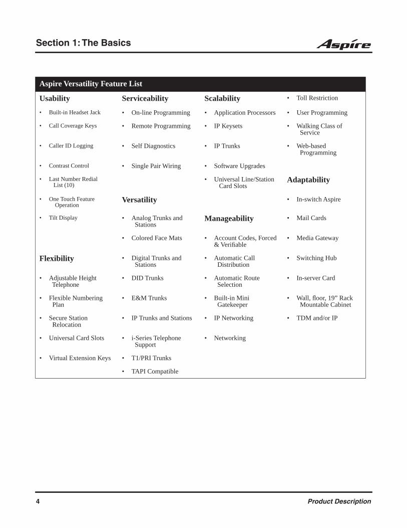
Aspire Versatility Feature List
Usability Serviceability Scalability • Toll Restriction
• Built-in Headset Jack • On-line Programming • Application Processors • User Programming
• Call Coverage Keys • Remote Programming • IP Keysets • Walking Class of Service
• Caller ID Logging • Self Diagnostics • IP Trunks • Web-based Programming
• Contrast Control • Single Pair Wiring • Software Upgrades
• Last Number Redial List (10)
• Universal Line/Station Card Slots
Adaptability
• One Touch Feature Operation
Versatility • In-switch Aspire
• Tilt Display • Analog Trunks and Stations
Manageability • Mail Cards
• Colored Face Mats • Account Codes, Forced & Verifiable
• Media Gateway
Flexibility • Digital Trunks and Stations
• Automatic Call Distribution
• Switching Hub
• Adjustable Height Telephone
• DID Trunks • Automatic Route Selection
• In-server Card
• Flexible Numbering Plan
• E&M Trunks • Built-in Mini Gatekeeper
• Wall, floor, 19” Rack Mountable Cabinet
• Secure Station Relocation
• IP Trunks and Stations • IP Networking • TDM and/or IP
• Universal Card Slots • i-Series Telephone Support
• Networking
• Virtual Extension Keys • T1/PRI Trunks
• TAPI Compatible
4 Product Description

Section 2: Components
2
Section 2: Components
The Telephones
Make a note. . .For your convenience. . . there is a Parts List located at the end of this guide. You should find this list helpful when selecting system equipment. More detailed tools are also available — ask your Account Representative for the specifics.
34-Button Super Display Telephone – P/Ns 0890049 & 0890050The Super Display Telephone, which is supported with soft-ware 1.07 or higher, is the system's premier telephone instru-ment, featuring an interactive 9-line, 24-character display with 12 associated interactive keys. As the Super Display Telephone user processes calls, the interactive key functions change to provide intuitive access to the system's most sophisticated features. Every Super Display Telephone has a built-in speakerphone for full Handsfree operation. Handsfree Answerback and Intercom voice-announce capability is also standard.
The telephone's 24 programmable function keys can be customized by the user for one-button access to co-workers, features like Paging or Park or specific outside lines. The Dual LEDs in each programmable key help the user see which calls are for them and which features are active. Access to other commonly used features is simplified by 15 fixed feature keys.
In addition, the Super Display Telephone provides a built-in wall-mount bracket, as well as adjust-able legs which allow each phone to be angled at a height which best suits the user.
Note that the three IP adapters (IP, ADA2, and PSA) do not work on the Super Display Telephones.
At a glance
Super Display Telephone - Part Numbers 0890049 & 0890050Function Keys: Accepts 110-Button DSS: Accepts 24-Button DLS: Handsfree (Speakerphone): Dual LEDs: ADA Adapter: ADA2 Adapter: No APA Adapter: APR Adapter: CTA Adapter: CTU Adapter: ILPA Adapter: NoIP Adapter: No PSA Adapter: No
Product Description 5
Section 2: Components
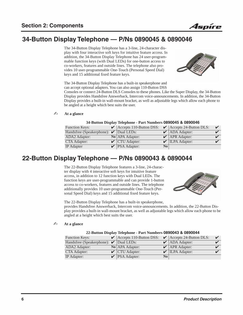
34-Button Display Telephone — P/Ns 0890045 & 0890046The 34-Button Display Telephone has a 3-line, 24-character dis-play with four interactive soft keys for intuitive feature access. In addition, the 34-Button Display Telephone has 24 user-program-mable function keys (with Dual LEDs) for one-button access to co-workers, features and outside lines. The telephone also pro-vides 10 user-programmable One-Touch (Personal Speed Dial) keys and 15 additional fixed feature keys.
The 34-Button Display Telephone has a built-in speakerphone and can accept optional adapters. You can also assign 110-Button DSS Consoles or connect 24-Button DLS Consoles to these phones. Like the Super Display, the 34-Button Display provides Handsfree Answerback, Intercom voice-announcements. In addition, the 34-Button Display provides a built-in wall-mount bracket, as well as adjustable legs which allow each phone to be angled at a height which best suits the user.
At a glance
22-Button Display Telephone — P/Ns 0890043 & 0890044The 22-Button Display Telephone features a 3-line, 24-charac-ter display with 4 interactive soft keys for intuitive feature access, in addition to 12 function keys with Dual LEDs. The function keys are user-programmable and can provide 1-button access to co-workers, features and outside lines. The telephone additionally provides 10 user-programmable One-Touch (Per-sonal Speed Dial) keys and 15 additional fixed feature keys.
The 22-Button Display Telephone has a built-in speakerphone, provides Handsfree Answerback, Intercom voice-announcements. In addition, the 22-Button Dis-play provides a built-in wall-mount bracket, as well as adjustable legs which allow each phone to be angled at a height which best suits the user.
At a glance
34-Button Display Telephone - Part Numbers 0890045 & 0890046Function Keys: Accepts 110-Button DSS: Accepts 24-Button DLS: Handsfree (Speakerphone): Dual LEDs: ADA Adapter: ADA2 Adapter: No APA Adapter: APR Adapter: CTA Adapter: CTU Adapter: ILPA Adapter: IP Adapter PSA Adapter: No
22-Button Display Telephone - Part Numbers 0890043 & 0890044Function Keys: Accepts 110-Button DSS: Accepts 24-Button DLS: Handsfree (Speakerphone): Dual LEDs: ADA Adapter: ADA2 Adapter: No APA Adapter: APR Adapter: CTA Adapter: CTU Adapter: ILPA Adapter: IP Adapter: PSA Adapter: No
6 Product Description

Section 2: Components
2
22-Button Standard Telephone — P/Ns 0890041 & 0890042The 22-Button Telephone offers similar capabilities as the 22-Button Display Telephone, but excludes the alphanumeric display and soft keys.
At a glance
2-Button Telephone — P/Ns 0890047 & 0890048
The Digital 2-Button Telephone offers many keyset features and conveniences at an analog station set price. Handsfree Answer-back lets users answer Intercom calls without touching the phone. The 11 fixed feature keys provide quick access to many essential features, and the Message Waiting lamp always shows when there are unanswered messages.
At a glance
Cordless Telephone — P/N 730088 & 730087The Aspire System, with software 1.07 or higher, supports the Cordless Telephone. The DTR-4R-2 Cordless II (P/N 730088) is a 900 MHz spread-spectrum digital cordless telephone that provides mobility, flexibility and convenience for those who spend much of the workday away from their desk. Fully integrated with the tele-phone system, the DTR-4R-2 Cordless II offers many standard features such as Park, Do Not Disturb, Hotline, Voice Over and Voice Mail. Normally paired with a companion keyset for improved 1-button call coverage capabilities, the DTR-4R-2 Cordless II will also work as a stand-alone telephone.
Where users require greater range on the cordless phones and 3 or less cordless phones are being used at a specific site, the DTR-4R-2 Cordless II phone is recommended.
22-Button Telephone - Part Numbers 0890041 & 0890042Function Keys: Accepts 110-Button DSS: Accepts 24-Button DLS: Handsfree (Speakerphone): Dual LEDs: ADA Adapter: ADA2 Adapter: No APA Adapter: APR Adapter: CTA Adapter: CTU Adapter: ILPA Adapter: IP Adapter PSA Adapter: No
2-Button Telephone - Part Numbers 0890047 & 0890048Function Keys: Accepts 110-Button DSS: Accepts 24-Button DLS: NoHandsfree (Speakerphone): Dual LEDs: ADA Adapter: NoADA2 Adapter: No APA Adapter: No APR Adapter: NoCTA Adapter: No CTU Adapter: No ILPA Adapter: NoIP Adapter: No PSA Adapter: No
Product Description 7
Section 2: Components
Complemented by 4 fully programmable function keys (with LEDs), the DTR-4R-2 Cordless II achieves a whole new level of convenience and mobility. An easy-to-read LCD display, volume controls, a rechargeable nickel-cadmium battery pack and a handy belt clip round out the elegant and affordable DTR-4R-2 Cordless II Phone. This phone provides 10 channels.
A second Cordless Phone is also available: the Cordless Lite II (P/N 730087). The Cordless Lite II offers the same features as the DTR-4R-2 Cordless II except that it uses a NiMH battery and has FM modulation (single channel) instead of the spread spectrum modulation.
Where more than 3 cordless phones are to be used at one specific site, the Cord-less Lite II phone is recommended. This phone provides 30 channels.
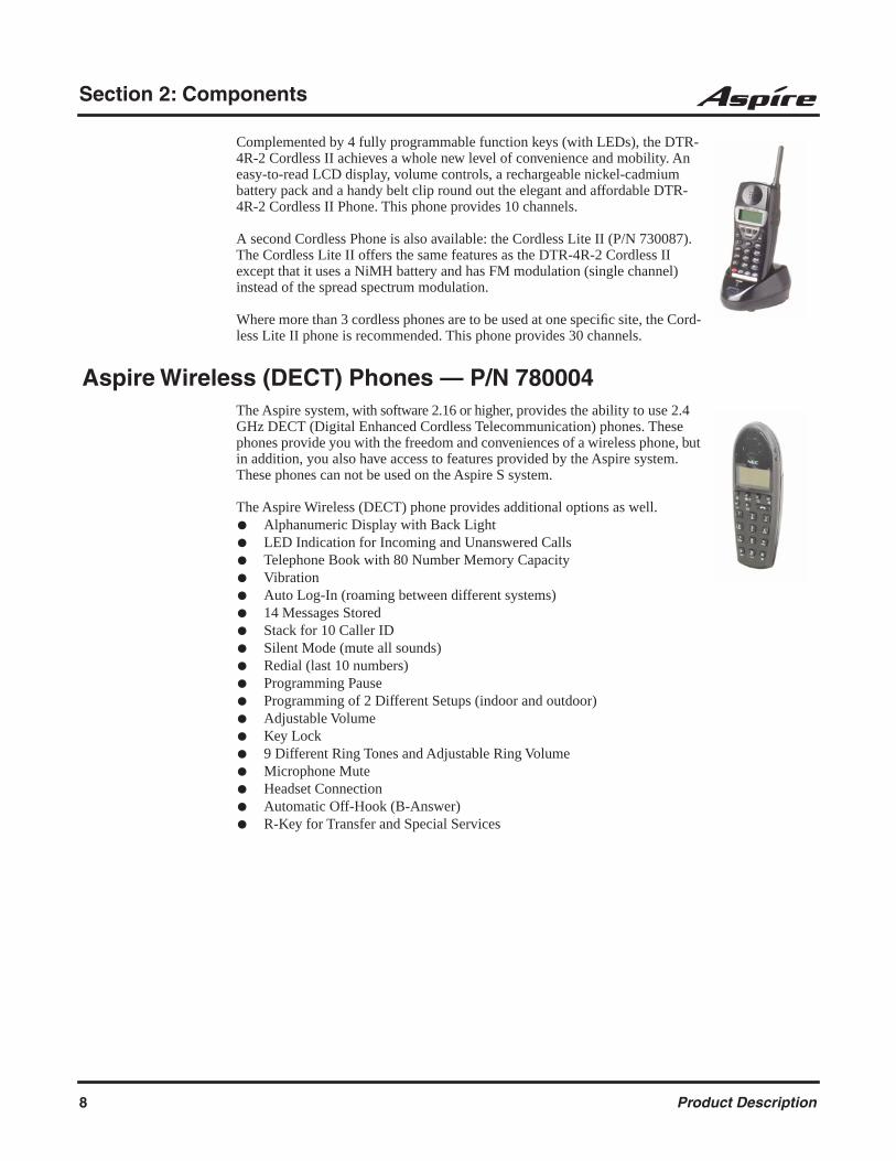
Aspire Wireless (DECT) Phones — P/N 780004The Aspire system, with software 2.16 or higher, provides the ability to use 2.4 GHz DECT (Digital Enhanced Cordless Telecommunication) phones. These phones provide you with the freedom and conveniences of a wireless phone, but in addition, you also have access to features provided by the Aspire system. These phones can not be used on the Aspire S system.
The Aspire Wireless (DECT) phone provides additional options as well. Alphanumeric Display with Back Light LED Indication for Incoming and Unanswered Calls Telephone Book with 80 Number Memory Capacity Vibration Auto Log-In (roaming between different systems) 14 Messages Stored Stack for 10 Caller ID Silent Mode (mute all sounds) Redial (last 10 numbers) Programming Pause Programming of 2 Different Setups (indoor and outdoor) Adjustable Volume Key Lock 9 Different Ring Tones and Adjustable Ring Volume Microphone Mute Headset Connection Automatic Off-Hook (B-Answer) R-Key for Transfer and Special Services
8 Product Description
Section 2: Components
2
Keyset Adapters
Each Aspire keyset (except the 2-Button telephone) accepts the following optional adapters, though there are limitations with phone types (such as IP) and adapter compatibility. Each telephone can have up to two adapters installed except when an IP adapter is used. This adapter uses the full space on the keyset, preventing any other adapter installation. In addition, the IP adapter cannot be used on a Super Display telephone.
You can install one of these. . .
Call Recording Adapter (ADA) (P/N 0890055)Using the ADA Adapter provides a recording jack connection which provides a connection from a telephone to an external tape recorder or speaker.
Analog Interface with Ringing (APR) (P/N 0890056)The APR provides an analog interface for a keyset. The APR provides ringing which allows the connected device to be used for incoming and outgoing calls. It can use the same extension number as the keyset (B1 channel) or it can have its own extension number (B2 channel). The APR does not support reverse polarity, message waiting lamping, or Caller ID.
This adapter requires an AC Adapter (AC-2R), P/N 780135.The APR for the B1 channel consumes no ports, however, the B2 channel consumes 1
port, ranging from 512 to 1 in descending order.
Analog Interface without Ringing (APA) (P/N 0890057)The APA provides an analog interface for a keyset. The connected device is used for outgoing calls only (for example, when using a modem). It does not provide ringing. When an analog device is in use, the keyset cannot be used (as the same port number is used for both devices). If both devices are picked up at the same time, the analog device takes priority. The APA does not support reverse polarity, message waiting lamping, or Caller ID.
RS-232C Adapter (CTA) (P/N 0890058)Provides a serial interface (RS-232C) connector. This can be used for SMDR or TAPI (1.4) or sys-tem reporting.
Speakerphone Adapter (HF-R) (P/N 0890062 & 0890063)Offers 22-Button, 34-Button, and Super Display keysets high quality speakerphone capability.
This adapter requires an AC Adapter (AC-2R), P/N 780135.
USB Adapter (CTU) (P/N 0890059)Provides a USB connector. This can be used for either SMDR, TAPI (1.4) or system reporting.
This adapter requires an AC Adapter (AC-2R), P/N 780135.
24-Button DLS Console (P/N 0890053 & 0890054)Refer to the “110-Button DSS Console and 24-Button DLS Console” on 24-Button DLS Console — P/Ns 0890053 & 0890054 (page 12) for more details.
Product Description 9
Section 2: Components
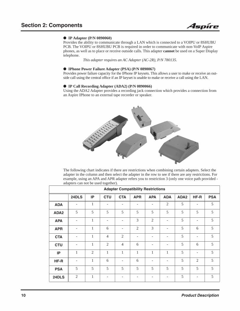
IP Adapter (P/N 0890060)Provides the ability to communicate through a LAN which is connected to a VOIPU or 8SHUBU PCB. The VOIPU or 8SHUBU PCB is required in order to communicate with non-VoIP Aspire phones, as well as to place or receive outside calls. This adapter cannot be used on a Super Display telephone.
This adapter requires an AC Adapter (AC-2R), P/N 780135.
IPhone Power Failure Adapter (PSA) (P/N 0890067)Provides power failure capacity for the IPhone IP keysets. This allows a user to make or receive an out-side call using the central office if an IP keyset is unable to make or receive a call using the LAN.
IP Call Recording Adapter (ADA2) (P/N 0890066)Using the ADA2 Adapter provides a recording jack connection which provides a connection from an Aspire IPhone to an external tape recorder or speaker.
The following chart indicates if there are restrictions when combining certain adapters. Select the adapter in the column and then select the adapter in the row to see if there are any restrictions. For example, using an APA and APR adapter refers you to restriction 3 (only one voice path provided - adapters can not be used together).
Adapter Compatibility Restrictions
24DLS IP CTU CTA APR APA ADA ADA2 HF-R PSA
ADA - 1 - - - - 2 5 - 5
ADA2 5 5 5 5 5 5 5 5 5 5
APA - 1 - - 3 2 - 5 - 5
APR - 1 6 - 2 3 - 5 6 5
CTA - 1 4 2 - - - 5 - 5
CTU - 1 2 4 6 - - 5 6 5
IP 1 2 1 1 1 1 1 5 - 5
HF-R - 1 6 - 6 - - 5 2 5
PSA 5 5 5 5 5 5 5 5 5 5
24DLS 2 1 - - - - - 5 - 5
10 Product Description

Section 2: Components
2
When installing the adapters, the keyset should first be unplugged from the system. Also note that the adapters may have an AC/DC power jack. Power is not required for all the adapters. You should refer to the information for the specific adapter to determine whether a power source is needed.Telephones with any of these adapters installed cannot be wall-mounted. The bracket will not accommodate the adapter(s).
1 = The IP Adapter takes the full space provided for adapters on the keysets. Therefore, if an IP adapter is installed, no other adapters can be used.
2 = Only one adapter of the same type can be used on a keyset.
3 = As there is only one voice path provided for adapters, the APR and APA adapters can not both be used on the same keyset.
4 = Due to protocol collision, the CTU and CTA adapters can not both be used on the same keyset.
5 = The ADA2 and PSA Adapters can only be installed on the Aspire IPhone, which only has one adapter connection. Therefore, if either the ADA2 or PSA is installed, no other adapters can be used.
6 = As this adapter requires the AC power adapter, it can not be installed on a phone with an APR or Speakerphone adapter, which also requires power. The placement of the AC power adapter plug will not allow the unit installed on the left side of the phone to receive power.
Product Description 11

Section 2: Components
Optional Equipment
2PGDAD Module — P/N 0891027 The 2PGDAD module provides two circuits which allow connection to external terminals such as: Door Box
(Aspire S: 4 max. per system, Aspire: 8 max. per system) External Speaker with Amplifier
(Aspire S: 4 maximum with 2PGDAD modules, Aspire: 8 maximum with 2PGDAD modules, 1 on the NTCPU)
External Music Source (external MOH) (Aspire S: 8 maximum per system, Aspire: 96 maximum per system)
External Recording System(Aspire S: 8 maximum per system, Aspire: 96 maximum per system)
External Ringing
The Aspire S supports a total of 10 2PGDAD modules on the system which can be used within the feature maximums indicated above. The Aspire supports a total of 56 2PGDAD modules on the sys-tem which can be used within the feature maximums indicated above.
The 2PGDAD module also provides multi-purpose controls. These control relays can be used for controlling the external amplifier, external music source and door lock control with the use of a Door Box. The Aspire S system allows for up 8 general purpose relays with the 2PGDAD modules. The Aspire system allows for up 8 general purpose relays with the 2PGDAD modules and 1 on the NTCPU for a maximum of 9.
The 2PGDAD module connects to any available digital extension port. The terminal connections made within the PGDAD module and the jumper settings determine what features are used for each circuit.
110-Button DSS Console — P/Ns 0890051 & 0890052 24-Button DLS Console — P/Ns 0890053 & 0890054
The DSS (Direct Station Selection) Console gives a keyset user a Busy Lamp Field (BLF) and one-button access to extensions, trunks and system features. The 110-Button DSS Console pro-vides an additional 100 programmable keys, while the 24-Button DLS Console provides 24 programmable keys. The 110-Button DSS also has 10 fixed feature keys for Paging, calling Door Boxes, activating Night Service and enabling DSS Console Alternate Answer. There are also two keys that allow “shifting” between the first and second set of 100 extensions.
12 Product Description

Section 2: Components
2
Keep the following in mind when installing DSS Consoles:
A 110-Button DSS Console requires a separate digital station port.
A 24-Button DLS Console does not require a separate station port.
The system allows for a maximum of 4 (Aspire S) or 32 (Aspire) 110-button DSS Consoles. One extension can have a maximum of 4 110-button DSS Consoles. As the 24-button DLS Console is connected to the bottom of the phone, an extension can only have one 24-button DLS Console installed, but each extension in the system can have a 24-button Console (maximum of 24 on Aspire S or 256 on Aspire). An extension can have a 24-button DLS Console and 4 110-button DSS consoles installed/assigned.
A 24-button DLS Console cannot be installed on an IPhone.
By default, the 24-Button DLS Console has no keys defined. These keys can be programmed as line keys, extension DSS keys, or programmable function keys using Program 15-07. To program the keys, use the extension number to which the DLS is installed and, regardless of the type of keyset connected, start programming the DLS keys at key number 25. Service codes 851 and 852 can also be used to program these keys if allowed by an extension’s Class of Service.
By default, the 110-Button DSS Console has extension DSS keys defined. These keys can be programmed as line keys, extension DSS keys, or programmable function keys using Program 30-03-01. Service codes 851 and 852 can also be used to program these keys if allowed by an extension’s Class of Service.
For additional information, refer to Direct Station Selection (DSS) Console in the Software Manual.
Audio Emcee Kit — P/N 750316The Audio Emcee message on hold system provides the ability to use a CD-based on-hold messag-ing system connected to the Aspire through the music on hold (MOH) port. When business calls are placed on hold, callers will hear advertisements that can help enhance the company image, cross sell products and services and reduce caller hangs-ups by keeping callers entertained and informed. Callers will hear programmed selections and this cycle will repeat until the call is answered.
The kit includes: MOH Unit Infrared Remote RCA Connecting Cable Starter CD with 24 Message/Music Tracks
(8 music tracks, 8 courtesy tracks, 8 holiday tracks) Certificate Good for 8 Customized Messages Operating Guide 1 Year License
Product Description 13

Section 2: Components
Door Box — P/N 92245The Door Box is a self-contained Intercom unit typically used to monitor an entrance door. A visitor at the door can press the Door Box call button (like a door bell). The Door Box then sends chime tones to all extensions programmed to receive chimes. The Door Box is weather-tight, but where possible, should have some coverage from the weather. A 2PGDAD Module is required for this feature.
Each 2PGDAD module audio output can optionally support two analog Door Boxes. In addition, you can connect each circuit’s control relay to an electric door strike. This allows an extension user to remotely activate the door strike while talking to a visitor at the Door Box. The control relays are normally open. The NTCPU also provides 1 relay. This relay is defined as relay ‘0’ in program-ming. The relays on the 2PGDAD modules are numbered 1-8. The system can have up to four (Aspire S) or eight (Aspire) Door Boxes.
HeadsetsHeadsets are perfect for users who spend a lot of time on the phone. They enable users to become more productive by freeing their hands while talking on the phone and also prevents neck strain from trying to balance the handset between their ear and shoulder. The following modular headsets are compatible with the Aspire system.
Polaris™ Supra® Monaural, Noise Cancelling (P/N 750636)
Polaris™ Supra® Binaural, Noise Cancelling (P/N 750633)
Polaris™ Supra Monaural (P/N 750632)
Polaris™ Encore Monaural - Voice Tube (P/N 750634)
Polaris™ Encore® Binaural, Noise Cancelling (P/N 750635)
Polaris Tristar - Voice Tube (P/N 750630)
Polaris Mirage - Voice Tube (P/N 750631)
CT-11 Cordless Headset Telephone (P/N 730089)
CT-11 Cordless Headset Telephone (P/N 730089)
The CT-11 is a 2.4GHz cordless headset which connects to an analog port or an analog telephone line as a stand-alone unit or to an analog port adapter (APR, P/N 0890056). When the APR is set up as the same extension of the telephone, you can use the headset to answer and make calls using the cordless headset. The CT-11 offers Caller ID, but only if it is connected to an analog port on an ana-log station card. The CT-11 will not receive Caller ID if it is connected to an APA or APR adapter (these adapters do not output Caller ID).
The number of units which can be used on the system is greatly affected by the environment. The closer or smaller the area, the smaller the number of units which can be used. It is recommended to start with 3 or less. If there are no conflicts between the telephones, you can try adding additional units (up to 5 would be the recommended maximum).
When using wireless LAN, keep in mind that although there should not be a problem with interfer-ence from WLAN’s, 802.11b and 802.11g both share the same frequency as the CT-11 telephone. In theory, the CT-11 is a narrow band high power device where as the 802.11b and 802.11g are both wide band low power technologies. Therefore, the higher power CT-11 could disrupt the low power device and slow the data network. There are, however, many exceptions to this (for example, if the WLAN uses highly directional antennas, higher power relays between buildings, etc.). The CT-11 can not lock down channels, unlike the 802.11b and 802.11g.
14 Product Description
Section 2: Components
2
The CT-11 features include: 2.4 GHz Cordless Headset Phone Range of Up to 150’ 6 Hours of Talk Time, 80 Hours Standby Time Audible Low Battery Indicator Single Line Operation Ultra-Compact Remote Unit with Belt Clip Variable Range Volume Control 10 Speed Dial Numbers Page/Find Feature Redial/Flash Mute with Audible Reminder Talk/Charge/Power Indicator Lights Built-in Headset Stand
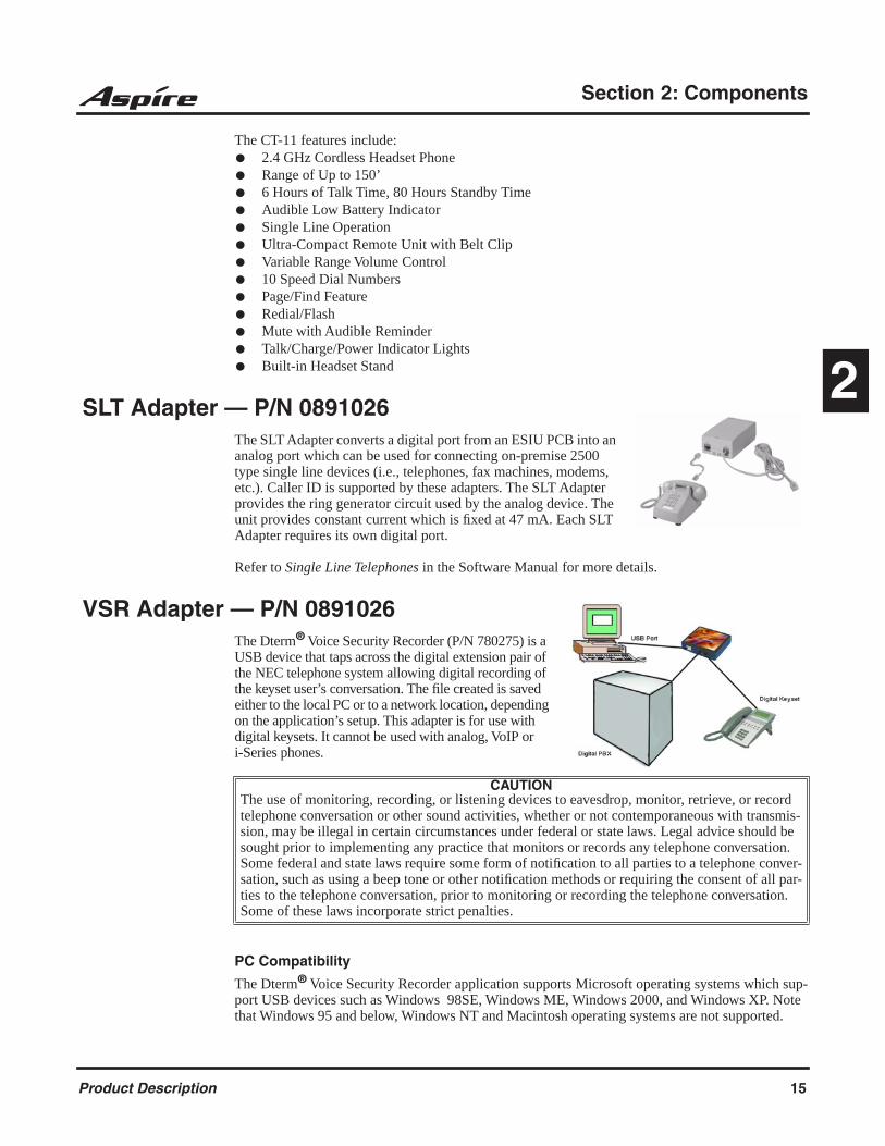
SLT Adapter — P/N 0891026The SLT Adapter converts a digital port from an ESIU PCB into an analog port which can be used for connecting on-premise 2500 type single line devices (i.e., telephones, fax machines, modems, etc.). Caller ID is supported by these adapters. The SLT Adapter provides the ring generator circuit used by the analog device. The unit provides constant current which is fixed at 47 mA. Each SLT Adapter requires its own digital port.
Refer to Single Line Telephones in the Software Manual for more details.
VSR Adapter — P/N 0891026The Dterm® Voice Security Recorder (P/N 780275) is a USB device that taps across the digital extension pair of the NEC telephone system allowing digital recording of the keyset user’s conversation. The file created is saved either to the local PC or to a network location, depending on the application’s setup. This adapter is for use with digital keysets. It cannot be used with analog, VoIP or i-Series phones.
PC Compatibility
The Dterm® Voice Security Recorder application supports Microsoft operating systems which sup-port USB devices such as Windows 98SE, Windows ME, Windows 2000, and Windows XP. Note that Windows 95 and below, Windows NT and Macintosh operating systems are not supported.
CAUTIONThe use of monitoring, recording, or listening devices to eavesdrop, monitor, retrieve, or record telephone conversation or other sound activities, whether or not contemporaneous with transmis-sion, may be illegal in certain circumstances under federal or state laws. Legal advice should be sought prior to implementing any practice that monitors or records any telephone conversation. Some federal and state laws require some form of notification to all parties to a telephone conver-sation, such as using a beep tone or other notification methods or requiring the consent of all par-ties to the telephone conversation, prior to monitoring or recording the telephone conversation. Some of these laws incorporate strict penalties.
Product Description 15
Section 2: Components
Aspire S Common Equipment
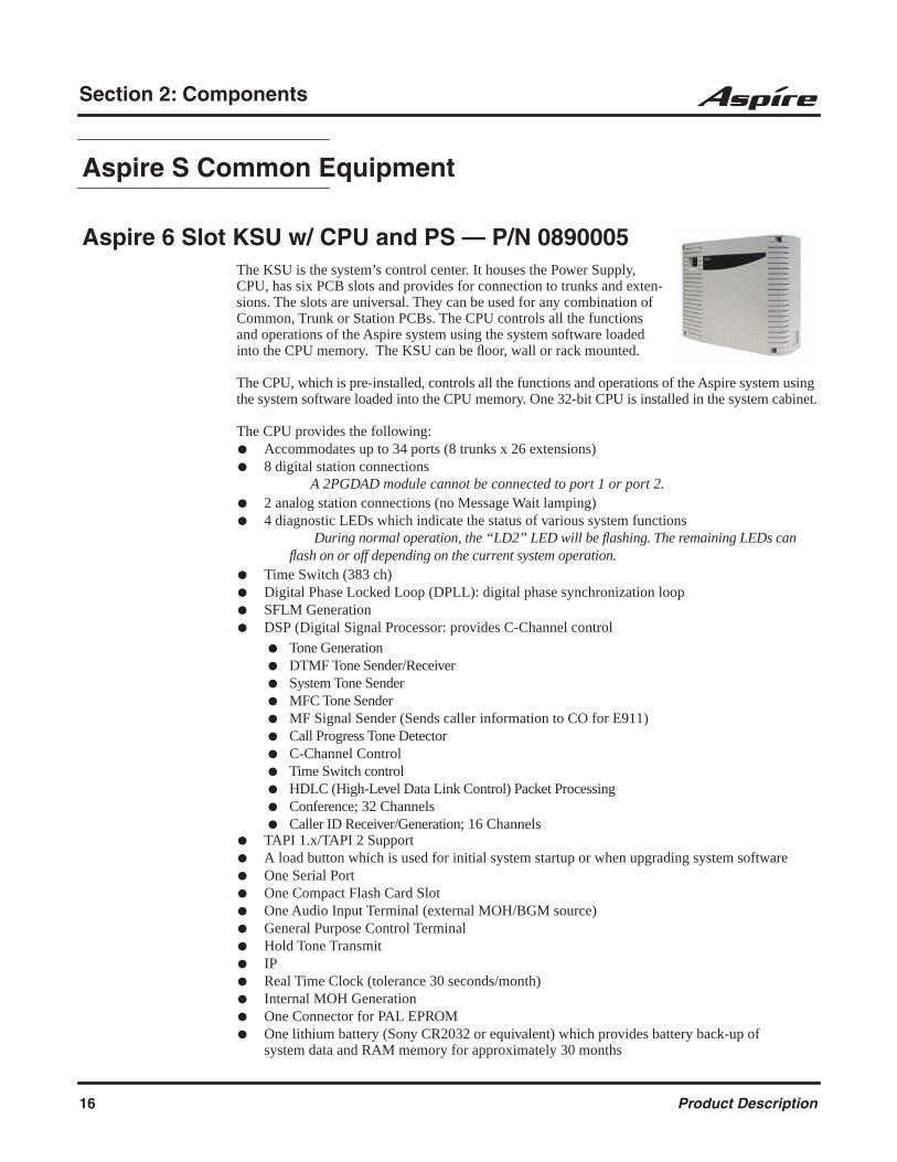
Aspire 6 Slot KSU w/ CPU and PS — P/N 0890005The KSU is the system’s control center. It houses the Power Supply, CPU, has six PCB slots and provides for connection to trunks and exten-sions. The slots are universal. They can be used for any combination of Common, Trunk or Station PCBs. The CPU controls all the functions and operations of the Aspire system using the system software loaded into the CPU memory. The KSU can be floor, wall or rack mounted.
The CPU, which is pre-installed, controls all the functions and operations of the Aspire system using the system software loaded into the CPU memory. One 32-bit CPU is installed in the system cabinet.
The CPU provides the following: Accommodates up to 34 ports (8 trunks x 26 extensions) 8 digital station connections
A 2PGDAD module cannot be connected to port 1 or port 2. 2 analog station connections (no Message Wait lamping) 4 diagnostic LEDs which indicate the status of various system functions
During normal operation, the “LD2” LED will be flashing. The remaining LEDs can flash on or off depending on the current system operation.
Time Switch (383 ch) Digital Phase Locked Loop (DPLL): digital phase synchronization loop SFLM Generation DSP (Digital Signal Processor: provides C-Channel control
Tone Generation DTMF Tone Sender/Receiver System Tone Sender MFC Tone Sender MF Signal Sender (Sends caller information to CO for E911) Call Progress Tone Detector C-Channel Control Time Switch control HDLC (High-Level Data Link Control) Packet Processing Conference; 32 Channels Caller ID Receiver/Generation; 16 Channels
TAPI 1.x/TAPI 2 Support A load button which is used for initial system startup or when upgrading system software One Serial Port One Compact Flash Card Slot One Audio Input Terminal (external MOH/BGM source) General Purpose Control Terminal Hold Tone Transmit IP Real Time Clock (tolerance 30 seconds/month) Internal MOH Generation One Connector for PAL EPROM One lithium battery (Sony CR2032 or equivalent) which provides battery back-up of
system data and RAM memory for approximately 30 months
16 Product Description
Section 2: Components
2
Floor/Desk Stand Mounting Brackets — P/N 0891303The Floor/Desk Stand Mounting Brackets are used to secure the KSU in an upright position to either a floor or desk area.
19” Rack Mount Bracket — P/N 0891300The 19” Rack Mount Bracket is required to install the KSU onto a 19” rack mounting system.
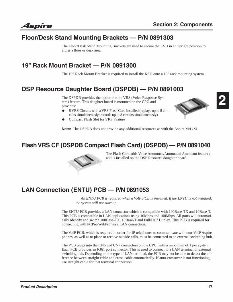
DSP Resource Daughter Board (DSPDB) — P/N 0891003The DSPDB provides the option for the VRS (Voice Response Sys-tem) feature. This daughter board is mounted on the CPU and provides: 8 VRS Circuits with a VRS Flash Card Installed (replays up to 8 cir-
cuits simultaneously; records up to 8 circuits simultaneously) Compact Flash Slot for VRS Feature
Note: The DSPDB does not provide any additional resources as with the Aspire M/L/XL.
Flash VRS CF (DSPDB Compact Flash Card) (DSPDB) — P/N 0891040The Flash Card adds Voice Announce/Automated Attendant features and is installed on the DSP Resource daughter board.
LAN Connection (ENTU) PCB — P/N 0891053An ENTU PCB is required when a VoIP PCB is installed. If the ENTU is not installed,
the system will not start up.
The ENTU PCB provides a LAN connector which is compatible with 100Base-TX and 10Base-T. This PCB is compatible in LAN applications using 10Mbps and 100Mbps. All ports will automati-cally identify and switch 100Base-TX, 10Base-T and Full/Half Duplex. This PCB is required for connecting with PCPro/WebPro via a LAN connection.
The VoIP PCB, which is required in order for IP telephones to communicate with non-VoIP Aspire phones, as well as to place or receive outside calls, must be connected to an external switching hub.
The PCB plugs into the CN6 and CN7 connectors on the CPU, with a maximum of 1 per system. Each PCB provides an RJ61 port connector. This is used to connect to a LAN terminal or external switching hub. Depending on the type of LAN terminal, the PCB may not be able to detect the dif-ference between straight cable and cross-cable automatically. If auto-crossover is not functioning, use straight cable for that terminal connection.
Product Description 17

Section 2: Components
If PoE (power over ethernet) is to be used to eliminate the separate power adapters, a separate power source is required. It is recommended that you use a power switch and/or power hub which is IEEE 802.3AF compliant. For example, the PowerDsine 6xxx series of products is unique in the fact that in addition to offering IEEE 802.3AF support, it also provides for the NEC proprietary detection and, therefore, the ILPA (In Line Power Adapter) is not required. For systems which require layer 2 switching capability and PoE, the NEC BlueFire 200/24 switch is recommended. This unit provides layer 2 switch capability in addition to being able to supply ethernet power to 24 NEC IP terminals. For this unit, power feeding is through the signal pair (1/2, 3/6) or spare pair (4/5, 7/8).
Aspire S Trunk PCBs
4 CO Loop Start Trunk Card (4COIU-S) — P/N 0891046
The Analog Trunk (4COIU) PCB provides: 4 analog loop start line/trunk circuits - no ground start is provided 4 trunk status LEDs 4 Caller ID Circuits 1 Power Failure Transfer Circuits 1 PCB status LED 1 PABX Grounding Wire
The CN5 and CN7 connectors each provide connection to 2 analog trunk ports, which are polarity sensitive (tip to tip, ring to ring). The power failure circuit, however, is not polarity sensitive. A maximum of 2 4COIUs per system is allowed.
2 DID/OPX (2DIOPU-S) Card — P/N 0891047The 2DIOPU PCB supports the analog DID and single line telephone interface functions (such as Off-Premise Extension). The function type is assigned in programming for each port.
The DIOPU PCB provides: 2 DID/OPX trunk circuits 2 DID/OPX trunk status LEDs 1 PCB status LED 1 PBXG Grounding Wire
The CN201 connector provides connection to 2 analog DID trunk ports, which are polarity sensitive (tip to tip, ring to ring). The OPX circuits, however, are not polarity sensitive. The DIOPU requires one universal slot, with 4 maximum PCBs per system. The system will assign either trunk or extension ports to the PCB based on the system programming (10-03-01). The PCB provides track resistance of 1500 ohms (PB loop) and 3000 ohms (DP loop) which includes the DC resistance of the terminal. This PCB requires system software 2.21 or higher.
18 Product Description
Section 2: Components
2
Aspire S Station PCBs
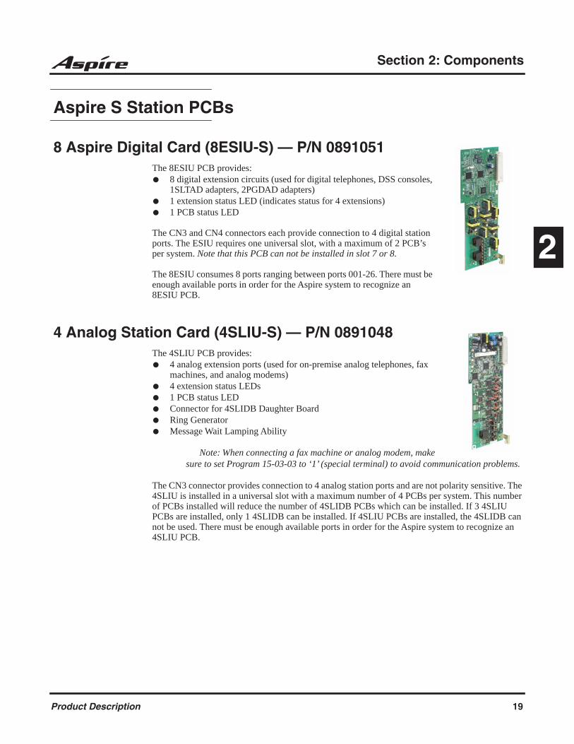
8 Aspire Digital Card (8ESIU-S) — P/N 0891051The 8ESIU PCB provides: 8 digital extension circuits (used for digital telephones, DSS consoles,
1SLTAD adapters, 2PGDAD adapters) 1 extension status LED (indicates status for 4 extensions) 1 PCB status LED
The CN3 and CN4 connectors each provide connection to 4 digital station ports. The ESIU requires one universal slot, with a maximum of 2 PCB’s per system. Note that this PCB can not be installed in slot 7 or 8.
The 8ESIU consumes 8 ports ranging between ports 001-26. There must be enough available ports in order for the Aspire system to recognize an 8ESIU PCB.
4 Analog Station Card (4SLIU-S) — P/N 0891048The 4SLIU PCB provides: 4 analog extension ports (used for on-premise analog telephones, fax
machines, and analog modems) 4 extension status LEDs 1 PCB status LED Connector for 4SLIDB Daughter Board Ring Generator Message Wait Lamping Ability
Note: When connecting a fax machine or analog modem, make sure to set Program 15-03-03 to ‘1’ (special terminal) to avoid communication problems.
The CN3 connector provides connection to 4 analog station ports and are not polarity sensitive. The 4SLIU is installed in a universal slot with a maximum number of 4 PCBs per system. This number of PCBs installed will reduce the number of 4SLIDB PCBs which can be installed. If 3 4SLIU PCBs are installed, only 1 4SLIDB can be installed. If 4SLIU PCBs are installed, the 4SLIDB can not be used. There must be enough available ports in order for the Aspire system to recognize an 4SLIU PCB.
Product Description 19

Section 2: Components
4 Analog Station Expansion Daughter Board (4SLIDB-S) — P/N 0891049
The 4SLIDB daughter board provides: 4 analog extension ports (used for on-premise analog telephones, fax
machines, and analog modems) Connector for 4SLIU PCB Ring Generator Message Wait Lamping Ability
Note: When connecting a fax machine or analog modem, make sure to set Program 15-03-03 to ‘1’ (special terminal) to avoid communication problems.
The CN3 connector provides connection to 4 analog station ports and are not polarity sensitive. The 4SLIDB is installed on the 4SLIU PCB. Up to 2 PCBs can be installed in the system maximum, but this number may be reduced depending on how many 4SLIU PCBs are installed. If 3 4SLIU PCBs are installed, only 1 4SLIDB can be installed. If 4SLIU PCBs are installed, the 4SLIDB can not be used.
20 Product Description
Section 2: Components
2
Voice Mail
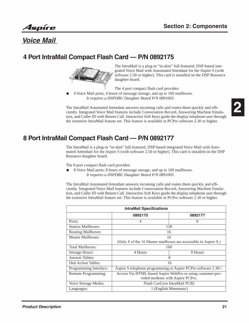
4 Port IntraMail Compact Flash Card — P/N 0892175The IntraMail is a plug-in “in-skin” full-featured, DSP-based inte-grated Voice Mail with Automated Attendant for the Aspire S (with software 2.50 or higher). This card is installed on the DSP Resource daughter board.
The 4 port compact flash card provides: 4 Voice Mail ports, 4 hours of message storage, and up to 160 mailboxes.
It requires a DSPDBU Daughter Board P/N 0891003.
The IntraMail Automated Attendant answers incoming calls and routes them quickly and effi-ciently. Integrated Voice Mail features include Conversation Record, Answering Machine Emula-tion, and Caller ID with Return Call. Interactive Soft Keys guide the display telephone user through the extensive IntraMail feature set. This feature is available in PCPro software 2.30 or higher.
8 Port IntraMail Compact Flash Card — P/N 0892177The IntraMail is a plug-in “in-skin” full-featured, DSP-based integrated Voice Mail with Auto-mated Attendant for the Aspire S (with software 2.50 or higher). This card is installed on the DSP Resource daughter board.
The 8 port compact flash card provides: 8 Voice Mail ports, 8 hours of message storage, and up to 160 mailboxes.
It requires a DSPDBU Daughter Board P/N 0891003.
The IntraMail Automated Attendant answers incoming calls and routes them quickly and effi-ciently. Integrated Voice Mail features include Conversation Record, Answering Machine Emula-tion, and Caller ID with Return Call. Interactive Soft Keys guide the display telephone user through the extensive IntraMail feature set. This feature is available in PCPro software 2.30 or higher.
IntraMail Specifications
0892175 0892177
Ports: 4 8Station Mailboxes: 128Routing Mailboxes: 16Master Mailboxes: 16
(Only 8 of the 16 Master mailboxes are accessible in Aspire S.)Total Mailboxes: 160Storage Hours: 4 Hours 8 HoursAnswer Tables: 8Dial Action Tables: 16Programming Interface: Aspire S telephone programming or Aspire PCPro software 2.30+. Remote Programming: Access Via HTML-based Aspire WebPro or using customer-pro-
vided modems with Aspire PCPro.Voice Storage Media: Flash Card (on IntraMail PCB)Languages: 1 (English Mnemonic)
Product Description 21

Section 2: Components
IP Interface Cards
4 CH VoIP Media Gateway (4VOIPU-S) — P/N 0891054An ENTU PCB is required when a VoIP PCB is installed. If the
ENTU is not installed, the system will not start up.
The 4VOIPU PCB is used for converting the RTP (Real Time Transfer Proto-col) packets via the IP network and PCM highway. The IP telephones are connected directly to the IP bus. When IP phones need to be connected to a conventional PCM-based digital circuit, this PCB converts the IP packet sig-nal into a PCM signal format and connects to the PCM time division switch.
The VOIPU PCB is required in order for IP telephones to communicate with non-VoIP Aspire phones, as well as to place or receive outside calls.
The 4VOIPU PCB provides: 4VOIPU PCB provides up to 4 channels Connector for the 4VOIPDB daughter board (providing an additional 4 channels) 1 PCB status LED DB status LED RIP session status LED PCMCIA slot LED Reset switch Load switch Boot jumper 1 run/block switch
A maximum of 3 PCBs per system are allowed. This provides 12 channels per system with the 4VOIPU (with the 4VOIPDB, 24 channels are available).
The separate software hub should be a 100Base/full duplex hub. To avoid network problems and to ensure good voice quality, do not use a Repeater Hub/10Base.
The Aspire VoIP supports H.323, H.325, and H.245 trunks and compressions of G.711, G.723.1, and G.729.
22 Product Description

Section 2: Components
2
4 CH VoIP Media Gateway Expansion Daughter Board (4VOIPDB-S) — P/N 0891055
The VOIPDB daughter board provides: 4 channels Connector for the 4VOIPU PCB (combination provides a maximum of 8 channels per slot)
The VOIPDB is installed on the VOIPU PCB with a maximum of 3 daughter boards per system. This provides a maximum of 24 channels when combining the 4VOIPU and 4VOIPDB.
When installing a 4VOIPU with a 4VOIPDB PCB, the system uses a consecutive block of 8 trunk ports if there are 8 ports available.When installing a VoIP PCB, the system automatically assigns trunk ports to match the card’s port capacity. For example, the 4VOIPU with a 4VOIPDB would take 8 trunk ports. Extension ports are not reserved until an IP phone is connected to the system. When the first IP phone is plugged in, the system takes the next four consecutive extension ports available and automatically assigns them as IP ports. The next three IP phones installed will use this group of ports. When the fifth IP phone is connected, the next 4 consecutive extension ports avail-able will be assigned as IP ports.
If the number of trunk ports reserved by the system is a concern (as it could be with the Aspire S system), install the trunk cards first, then install the VOIPU PCB. This will allow the trunks to be assigned to the COIU, DIOPU, etc. first. If there are not enough trunk ports available for the VoIP PCB, the system will still recognize the card and allow it to be used for IP phones.
If the PCB is not going to be used for trunks, the logical trunk ports can be set to ‘0’ in Program 10-03-01 : PCB Setup, but the physical trunk ports are still assigned to the PCB and cannot be used for any other PCB unless the PCB is deleted from the slot in Program 90-05 : Slot Control.
The Aspire VoIP supports H.323, H.325, and H.245 trunks and compressions of G.711, G.723.1, and G.729.
Product Description 23
Section 2: Components
IP Station Equipment
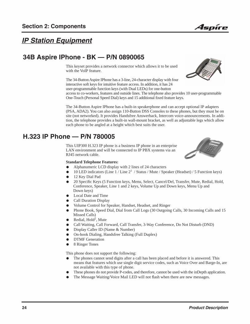
34B Aspire IPhone - BK — P/N 0890065This keyset provides a network connector which allows it to be used with the VoIP feature.
The 34-Button Aspire IPhone has a 3-line, 24-character display with four interactive soft keys for intuitive feature access. In addition, it has 24 user-programmable function keys (with Dual LEDs) for one-button access to co-workers, features and outside lines. The telephone also provides 10 user-programmable One-Touch (Personal Speed Dial) keys and 15 additional fixed feature keys.
The 34-Button Aspire IPhone has a built-in speakerphone and can accept optional IP adapters (PSA, ADA2). You can also assign 110-Button DSS Consoles to these phones, but they must be on site (not networked). It provides Handsfree Answerback, Intercom voice-announcements. In addi-tion, the telephone provides a built-in wall-mount bracket, as well as adjustable legs which allow each phone to be angled at a height which best suits the user.
H.323 IP Phone — P/N 780005This UIP300 H.323 IP phone is a business IP phone in an enterprise LAN environment and will be connected to IP PBX systems via an RJ45 network cable.
Standard Telephone Features: Alphanumeric LCD display with 2 lines of 24 characters 10 LED indicators (Line 1 / Line 21 / Status / Mute / Speaker (Headset) / 5 Function keys) 12 Key Dial Pad 20 Specific Keys (5 Function keys, Menu, Select, Cancel/Del, Transfer, Mute, Redial, Hold,
Conference, Speaker, Line 1 and 2 keys, Volume Up and Down keys, Menu Up and Down keys)
Local Date and Time Call Duration Display Volume Control for Speaker, Handset, Headset, and Ringer Phone Book, Speed Dial, Dial from Call Logs (30 Outgoing Calls, 30 Incoming Calls and 15
Missed Calls) Redial, Hold2, Mute Call Waiting, Call Forward, Call Transfer, 3-Way Conference, Do Not Disturb (DND) Display Caller ID (Name & Number) On-hook Dialing, Handsfree Talking (Full Duplex) DTMF Generation 8 Ringer Tones
This phone does not support the following: The phones cannot send digits after a call has been placed and before it is answered. This
means that features which use single digit service codes, such as Voice Over and Barge-In, are not available with this type of phone.
These phones do not provide P-codes, and therefore, cannot be used with the inDepth application. The Message Waiting/Voice Mail LED will not flash when there are new messages.
24 Product Description

Section 2: Components
2
VoIP Specific Features: H.323 v1, 2 Standard Compliant Gatekeeper Routed and Direct Routed Call Models Voice Codec: G.711 (64kbit/s, u-Law and A-law), G723.1, G729AB E.164 Dialing Acoustic Echo Cancellation (G.167) Rapid Configuration with DHCP or Statically Configured IP Address Voice Activity Detection (VAD) QoS (IEEE 802.1 p/q Based and DiffServ) Jitter Compensation 10/100 Base-T Ethernet Interface
1 Only one phone number will be assigned to this IP phone. Line 2 is not available for a gateway system
2 Hold, Transfer, Call Forward and Conference will not be available in the IP address call mode but in the phone number dial mode only
Aspire Soft Phone — P/N 0893641Aspire Soft Phone is a business phone which works on a personal computer. It enables various telephony functions using an IP network connecting with the Aspire S/Aspire system
This allows you to cap-italize on the advan-tages of a converged voice and data network whether you’re in the office or on the road. The Aspire Soft Phone application combines traditional business communication needs with the data applications you require.
The Aspire Soft Phone delivers high quality voice via a USB-connected handset or headset or via a PC sound card, microphone and speakers. The Aspire Soft Phone functions include, not only mak-ing and receiving calls, but also placing calls on hold, intercom calls, conferencing, etc. The appli-cation can display a layout of an Aspire keyset to allow for ease of operation. Using the cursor, simply point and click to operate the Aspire Soft Phone as you would an Aspire keyset.
Product Description 25

Section 2: Components
In-Line Power Adapter (ILPA-R) — P/N 780122The In-Line Power Adapter (ILPA-R), which is IEEE 802.3af compliant, detects power from a PoE-compatible ethernet switch and passes it to the IP terminal. The ILPA does the negotiation and detection with the switch and then relays the power to the IP terminal device. This provides an addi-tional way to power the NEC IP terminals (Aspire IPhone or Aspire Keyset with IP Adapter). With this adapter, the IP terminals on the Aspire can be powered using: Local power connecting the IP terminal to a local AC wall outlet using the AC-2R Adapter
(P/N 780135) NEC power supply PoE-managed switch (BlueFire 200/24) (in-line and spare pair detection) Aspire 8SHUBU PCB (P/N 0891021) (spare pair detection) Cisco Data Switch - CDP supported (in-line and spare pair detection) In-Line Power Adapter
Keep the following in mind when installing an ILPA: Only IP telephones supported by center feed can be used. This adapter can not be used with the H.323 telephones. When center feed is used, first unplug the adapter from the ethernet switch before changing the
SW1 setting on the back of the adapter. Please note that the ILPA-R adapter is intended for use with the Aspire IPhones (P/N 0890065)
and IP Adapters (P/N 0890060). Installing any other device into the telephone port of the ILPA-R may result in damage to the device.
When powering an IP phone using an ILPA-R adapter, the phone should not get connected to a port on the 8SHUBU PCB.
AC Adapter (AC-2R) — P/N 780135The AC Adapter is required for the IP adapter or Aspire IPhone if external power is needed. Also required for APR, CTU, and Speaker-phone optional keyset adapters.
26 Product Description

Section 2: Components
2
Aspire (M/L and XL) Common Equipment
Aspire 8 Slot KSU w/o PS — P/N 0890000The KSU is the system’s control center. It houses the Power Supply, has nine PCB slots and provides for connection to trunks and extensions. The first slot in the KSU is dedicated to the NTCPU. The next slot is a univer-sal slot which should be reserved for a Digital Station Card. The remain-ing seven slots are also universal. They can be used for any combination of Common, Trunk or Station PCBs. The KSU can be floor, wall or rack mounted.
You should plug a Digital Station Card into the first universal slot.
Aspire XL Power Supply Cabinet w/o PS — P/N 0890068The Aspire XL power supply cabinet accommodates up to two AC/DC power supplies. This cabinet is to be installed as the bottom cabinet of a 3-cabinet system (the top two cabinets containing the NTCPU, DC/DC Converters, and PCBs).
Note: The Aspire XL system can support mixed hardware configura-tions. With an Aspire XL AC/DC power supply cabinet and a DC/DC Converter in one cabinet, the second cabinet can contain up to two Aspire M/L power supplies (P/N 0891000).
Central Processing Unit (NTCPU) PCB — P/Ns 0891002 & 0891038 The NTCPU controls all the functions and operations of the Aspire system using the system software loaded into the NTCPU memory. One 32-bit NTCPU PCB must be installed in the CPU slot in the Main Cabinet. There are two versions of NTCPUs. The first version, P/N 0891002, is a 64-port basic NTCPU. The second version, P/N 0891038, is a feature-enhanced, 256 extension port NTCPU.
To upgrade from the basic 64-port NTCPU, a Feature Upgrade chip (P/N 0891039) is available. The NTCPU provides a connector (CN14) for the upgrade PAL EPROM chip. Make sure when installing this upgrade chip on the NTCPU that you wear a grounded wrist strap. Using software 4.0E and higher, the Feature Upgrade PAL chip (P/N 0891039), supports 128 ports for trunks, extensions, and voice mail (internal and external). With prior soft-ware, only 64 ports are available.
Product Description 27

Section 2: Components
The 64-port basic CPU (P/N 0891002), with the basic factory-installed PAL chip, provides: 64 ports maximum for trunks, extensions, and voice mail (internal or external) 64 ports maximum for the NEC Aspire Wireless 2.4 GHz and IP Phones 256 virtual extensions Supports the 4VOIPU PCB and 4VOIPDB Supports TAPI 1.x VRS (Requires DSPDB Daughter Board and software 2.00+ - prior to this software version,
the VRS is not supported by the basic factory-installed PAL chip) T1 Trunks (Requires software 4.0E+ - prior to this software version, this was not supported) PRI Trunks(Requires software 4.0E+ - prior to this software version, this was not supported) DSPDB Daughter Board (providing 32 channels for the DTMF Receiver, Call Progress Tone
Detection and Caller ID Receivers) (Requires software 4.0E+ - prior to this software version, the DSPDB did not support the additional channels)
Supports the 32ESIU PCB
NOT SUPPORTED by the 64-port basic CPU, with the basic factory-installed PAL chip:
The 64-port basic CPU (P/N 0891002), with the Feature Upgrade PAL chip, provides: 128 ports maximum for trunks, extensions, and voice mail (internal or external)
(Requires software 4.0E+ - prior to this software version, only 64 ports are supported) 128 ports maximum for the NEC Aspire Wireless 2.4 GHz and IP Phones
(Requires software 4.0E+ - prior to this software version, only 64 ports are supported) 256 virtual extensions Supports the 4VOIPU PCB and 4VOIPDB Supports TAPI 1.x VRS (Requires DSPDB Daughter Board)
The 64-port basic CPU, with the Feature Upgrade PAL chip, supports:
Expansion Cabinet Third-Party CTI/TAPI 2
16VOIPU PCB and 16VOIPDB
ACD
BRI S-Bus/T-Bus E&M Trunks Networking
Expansion Cabinet Third-Party CTI/TAPI 2 PRI Trunks
DSPDB Daughter Board (providing 32 channels for the DTMF Receiver, Call Progress Tone Detection and Caller ID Receivers)
16VOIPU PCB and 16VOIPDB
T1 Trunks ACD
BRI S-Bus/T-Bus E&M Trunks Networking 32ESIU PCB
28 Product Description

Section 2: Components
2
The enhanced CPU (P/N 0891038) provides: 200 trunk ports maximum 256 extension and voice mail (internal or external) ports maximum 512 ports maximum for the NEC Wireless 2.4 GHz and IP Phones (more than 256 Wireless
and IP phones reduces the number of available extension ports) 256 virtual extensions Supports the 4VOIPU PCB and 4VOIPDB Supports TAPI 1.x VRS (Requires DSPDB Daughter Board)
The enhanced CPU supports:
Each version of the NTCPU provides the following:
Five diagnostic LEDs which indicate the status of various system functions During normal operation, the “RUN” LED will be flashing and the remaining LEDs will be off.
1019x1019 Time Division Multiplex Switch (TDM Switch) Digital Phase Locked Loop (DPLL) Tone Generator DTMF Tone Sender 32 Tone Resources (for DTMF Receiver, Caller ID Receiver, and Call Progress Tone Detection) System Tone Sender MFC Tone Sender MF Signal Sender (Sends caller information to CO for E911) Call Progress Tone Detector C-Channel Control Conference; 64 Channels Caller ID Receiver; 32 Channels Caller ID Sender; 4 or 10 Channels for Analog Stations
This can be expanded up to 20 by disabling 32 channels of the Conference circuits and disabling the MFC Tone Sender.
A reset switch (RES) which can be used to reset the system A load switch (LOAD) which is used for initial system startup or when upgrading
system software One Serial Port One USB Port (requires USB driver - download from NEC web site) One Ethernet Port (10 Base-T/100 Base-TX) One PCMCIA Slot One EXIFU Interface Connector Two Audio Input Terminals One Audio Output Terminal One Night Mode Terminal for External Switch One Music On Hold External Source
Expansion Cabinet Third-Party CTI/TAPI 2 PRI Trunks
DSPDB Daughter Board (providing 32 channels for the DTMF Receiver, Call Progress Tone Detection and Caller ID Receivers)
16VOIPU PCB and 16VOIPDB
T1 Trunks ACD
BRI S-Bus/T-Bus E&M Trunks Networking 32ESIU PCB
Product Description 29

Section 2: Components
HDLC Packet Processing Real Time Clock (tolerance 30 seconds/month) Internal MOH Generation One Connector for DSPDBU Daughter Board One Connector for PAL EPROM One lithium battery (Sony CR2032 or equivalent) which provides battery back-up of
system data and RAM memory for approximately 30 months
Aspire M/L Power Supply — P/N 0891000The Power Supply provides the DC voltage for the Cabinet PCBs and all telephones connected to the Cabinet Station PCBs.
Each Aspire M/L system cabinet must have at least one power supply installed. In order to determine if a second power supply is required, refer to the load factor charts located in Section 2 of the Aspire Hardware Manual (P/N 0893100).
Note: One power supply can provide power to 64 analog or digital tele-phones. If more than 64 telephones are connected to a cabinet, a second power supply must be used.
Aspire XL Power Supply Set — P/N 0890069This set contains a power supply and DC/DC Converter required to convert an Aspire M/L system to an Aspire XL system, with expanded physical port capacity.
This kit includes the following: AC/DC Power Supply (IP1WW-PSADU-A1) for the Aspire
XL Power Supply Cabinet - P/N 0892011The Power Supply provides the DC voltage to the DC/DC Converter which, in turn, powers the PCB cabinet and all tele-phones connected to the station PCBs.
Up to two AC/DC Power Supplies maximum can be installed per Power Supply Cabinet. When two AC/DC Power Supplies are installed, two separate AC cords will each require an AC outlet connection from the bottom Power Supply Cabinet. Use the power cords included with the Aspire system cabi-net(s) for connecting the power supplies to the AC outlet. The Aspire system cabinet is no longer directly connected to an AC outlet with the AC/DC Power Supplies installed.
! IMPORTANT!
After removing a previously installed NTCPU, handle the PCB, carefully, from the edges. If certain solder points/resistors are touched on the back of the PCB, some RAM/temporary memory may be lost (ex: time, date, user-defined settings, etc.)
30 Product Description

Section 2: Components
2
Note: A multi-cabinet system can use different power supplies (0891000 and 0892011), however, if a cabinet has more than 128 -48V ports, the AC/DC power supply and DC/DC Converter is required.
If both AC/DC power supplies and DC/DC Converters are installed, then a maximum of 384 ports (greater than 128 ports in each cabinet) are supported by -48V output.
DC/DC Converter (IP1WW-PSDDU-A1) for the Aspire XL System Cabinet - P/N 0892012
A maximum of two DC/DC Converters are installed per system - one in each system cabinet.
A DC/DC Converter replaces the two power supplies (P/N 0891000) used in the system cabinet of the Aspire M/L system.
If an Aspire M/L system is upgraded to an Aspire XL, the existing power supplies will no longer be required as they are replaced by the DC/DC Converter.
Note: A multi-cabinet system can use different power supplies (0891000 and 0892011), however, if a cabinet has more than 128 -48V ports, the AC/DC power supply and DC/DC Converter is required.
If both AC/DC power supplies and DC/DC Converters are installed, then a maximum of 384 ports (greater than 128 ports in each cabinet) are supported by -48V output.
Cable for Power (connects the AC/DC Unit and DC/DC Unit) - P/N 0892013
This cable allows for a power connection from one AC/DC Power Supply in the bottom cabinet to one DC/DC Con-verter in the system cabinet.
Note: The power cord for the system cabinet (located on the back of the cabinet) is no longer required with this cable connection.
Cable for Signal (connects the AC/DC Unit and DC/DC Unit) - P/N 0892010
This cable allows for a signal connection from one AC/DC Power Supply in the bottom cabinet to one DC/DC Con-verter in the system cabinet.
Product Description 31

Section 2: Components
KSU Expansion Set — P/N 0891001This set is required to connect a second cabinet, allowing expansion from an 8 slot to a 16 slot system. It consists of an EXIFU PCB, EXIFU Cable and Joint Plate.
19” Rack Mount Bracket — P/N 0891300The 19” Rack Mount Bracket is required to install the KSU onto a 19” rack mounting system. If rack-mounting all three cabinets of an Aspire XL system, the power supply cabinet (P/N 0890068) must be mounted on a separate bracket due to the bracket weight requirements (150 lbs maximum).
Feature Upgrade for 0891002 — P/N 0891039The Feature Upgrade for the 0891002 is added to the 64 Port Basic CPU (0891002). It provides such features as 16 channel media gateway cards, ACD, T1/PRI, E&M, etc. Refer to the NTCPU info on Central Processing Unit (NTCPU) PCB — P/Ns 0891002 & 0891038 (page 27) for more.
With software 4.0E or higher, the Feature Upgrade PAL chip can support 128 ports for trunks, extensions, and voice mail (internal and external). With prior software, only 64 ports are available.
DSP Resource Daughter Board (DSPDB) — P/N 0891003The DSPDB provides additional DSP resources as well as the option for the VRS (Voice Response System) or Voice Mail features. This daughter board is mounted on the NTCPU and provides: 32 Tone Resources (for DTMF Receiver, Caller ID Receiver, and
Call Progress Tone Detection) 16 VRS Circuits with a VRS Flash Card Installed (replays up to 16
circuits simultaneously, recording: up to 8 circuits simultaneously) Compact Flash Slot for VRS Features
The receiver circuits are used for DTMF receivers, call progress tone detection, and Caller ID receivers.
VRS Compact Flash (DSPDB Compact Flash Card) (DSPDB) — P/N 0891040
The VRS Flash Card adds Voice Announce/Automated Attendant fea-tures and is installed on the DSP Resource daughter board.
32 Product Description

Section 2: Components
2
Aspire Trunk PCBs
4 CO Loop Start Trunk Card (4COIU-LS1) — P/N 0891005There are two different types of the COIU PCB. One providing ground start trunks - the other is for loop start trunks only.
The 4COIU-LS1 PCB provides: 4 analog loop start line/trunk circuits - no ground start is provided 4 trunk status LEDs 4 Caller ID Circuits 2 Power Failure Transfer Circuits 1 PCB status LED 1 run/block switch
The CN3 connector provides connection to 4 analog trunk ports, which are polarity sensitive (tip to tip, ring to ring). The power failure circuits, however, are not polarity sensitive. A maximum of 15 4COIU-LS1 PCBs per system is allowed, each PCB consuming 4 ports.
8 CO Loop Start Trunk Card (8COIU-LS1) — P/N 0891004The 8COIU-LSI provides the same features as the 4COIU-LS1 except for the following changes:
The 8COIU-LS1 PCB provides: 8 analog loop start line/trunk circuits - no ground start is provided 8 trunk status LEDs 8 Caller ID Circuits 2 Power Failure Transfer Circuits 1 PCB status LED 1 run/block switch
The CN3 and CN5 connectors each provide connection to 4 analog trunk ports, which are polarity sensitive (tip to tip, ring to ring). The power failure circuits, however, are not polarity sensitive. A maximum of 15 8COIU-LS1 PCBs per system is allowed, each PCB consuming 8 ports.
Product Description 33

Section 2: Components
4 CO Loop Start/Ground Start Trunk Card (4COIU-LG1) — P/N 0891029There are two different types of the COIU PCB. One providing ground start trunks - the other is for loop start trunks only.
The 4COIU-LG1 PCB provides: 4 analog ground start / loop start trunk circuits 4 trunk status LEDs 4 Caller ID Circuits 2 Power Failure Transfer Circuits 1 PCB status LED 1 run/block switch
The CN3 connector provides connection to 4 analog trunk ports, which are polarity sensitive (tip to tip, ring to ring). The power failure circuits, however, are not polarity sensitive. A maximum of 15 4COIU-LG1 PCBs per system is allowed, each PCB consuming 4 ports.
! Important! When using the COIU-LG1 PCB for ground start trunks, the PBX ground must be connected
or the trunks will not function correctly.
When connecting the RJ61 cables to the COIU PCB, note the position of the Power Failure connector. Do not confuse this connector as the trunk connector.
8 CO Loop Start/Ground Start Trunk Card (8COIU-LG1) — P/N 0891028The 8COIU-LG1 provides the same features as the 4COIU-LG1 except for the following changes:
The 8COIU-LG1 PCB provides: 8 analog ground start / loop start trunk circuits 8 trunk status LEDs 8 Caller ID Circuits 2 Power Failure Transfer Circuits 1 PCB status LED 1 run/block switch
The CN3 and CN5 connectors each provide connection to 4 analog trunk ports, which are polarity sensitive (tip to tip, ring to ring). The power failure circuits, however, are not polarity sensitive. A maximum of 15 8COIU-LG1 PCBs per system is allowed, each PCB consuming 8 ports.
! Important! When using the COIU-LG1 PCB for ground start trunks, the PBX ground must be connected
or the trunks will not function correctly.
When connecting the RJ61 cables to the COIU PCB, note the position of the Power Failure connector. Do not confuse this connector as the trunk connector.
34 Product Description
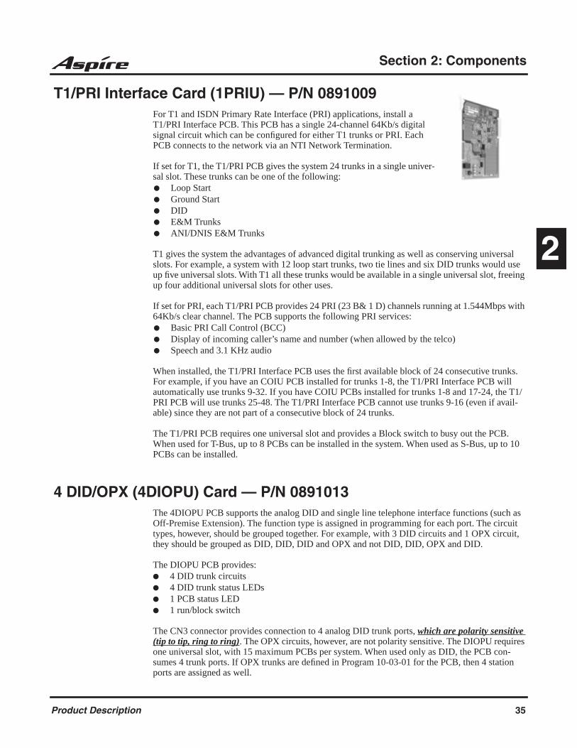
Section 2: Components
2
T1/PRI Interface Card (1PRIU) — P/N 0891009For T1 and ISDN Primary Rate Interface (PRI) applications, install a T1/PRI Interface PCB. This PCB has a single 24-channel 64Kb/s digital signal circuit which can be configured for either T1 trunks or PRI. Each PCB connects to the network via an NTI Network Termination.
If set for T1, the T1/PRI PCB gives the system 24 trunks in a single univer-sal slot. These trunks can be one of the following: Loop Start Ground Start DID E&M Trunks ANI/DNIS E&M Trunks
T1 gives the system the advantages of advanced digital trunking as well as conserving universal slots. For example, a system with 12 loop start trunks, two tie lines and six DID trunks would use up five universal slots. With T1 all these trunks would be available in a single universal slot, freeing up four additional universal slots for other uses.
If set for PRI, each T1/PRI PCB provides 24 PRI (23 B& 1 D) channels running at 1.544Mbps with 64Kb/s clear channel. The PCB supports the following PRI services: Basic PRI Call Control (BCC) Display of incoming caller’s name and number (when allowed by the telco) Speech and 3.1 KHz audio
When installed, the T1/PRI Interface PCB uses the first available block of 24 consecutive trunks. For example, if you have an COIU PCB installed for trunks 1-8, the T1/PRI Interface PCB will automatically use trunks 9-32. If you have COIU PCBs installed for trunks 1-8 and 17-24, the T1/PRI PCB will use trunks 25-48. The T1/PRI Interface PCB cannot use trunks 9-16 (even if avail-able) since they are not part of a consecutive block of 24 trunks.
The T1/PRI PCB requires one universal slot and provides a Block switch to busy out the PCB. When used for T-Bus, up to 8 PCBs can be installed in the system. When used as S-Bus, up to 10 PCBs can be installed.
4 DID/OPX (4DIOPU) Card — P/N 0891013The 4DIOPU PCB supports the analog DID and single line telephone interface functions (such as Off-Premise Extension). The function type is assigned in programming for each port. The circuit types, however, should be grouped together. For example, with 3 DID circuits and 1 OPX circuit, they should be grouped as DID, DID, DID and OPX and not DID, DID, OPX and DID.
The DIOPU PCB provides: 4 DID trunk circuits 4 DID trunk status LEDs 1 PCB status LED 1 run/block switch
The CN3 connector provides connection to 4 analog DID trunk ports, which are polarity sensitive (tip to tip, ring to ring). The OPX circuits, however, are not polarity sensitive. The DIOPU requires one universal slot, with 15 maximum PCBs per system. When used only as DID, the PCB con-sumes 4 trunk ports. If OPX trunks are defined in Program 10-03-01 for the PCB, then 4 station ports are assigned as well.
Product Description 35
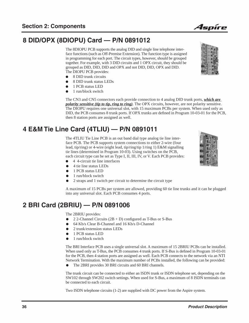
Section 2: Components
8 DID/OPX (8DIOPU) Card — P/N 0891012The 8DIOPU PCB supports the analog DID and single line telephone inter-face functions (such as Off-Premise Extension). The function type is assigned in programming for each port. The circuit types, however, should be grouped together. For example, with 3 DID circuits and 1 OPX circuit, they should be grouped as DID, DID, DID and OPX and not DID, DID, OPX and DID. The DIOPU PCB provides: 8 DID trunk circuits 8 DID trunk status LEDs 1 PCB status LED 1 run/block switch
The CN3 and CN5 connectors each provide connection to 4 analog DID trunk ports, which are polarity sensitive (tip to tip, ring to ring). The OPX circuits, however, are not polarity sensitive. The DIOPU requires one universal slot, with 15 maximum PCBs per system. When used only as DID, the PCB consumes 8 trunk ports. If OPX trunks are defined in Program 10-03-01 for the PCB, then 8 station ports are assigned as well.
4 E&M Tie Line Card (4TLIU) — P/N 0891011The 4TLIU Tie Line PCB is an out band dial type analog tie line inter-face PCB. The PCB supports system connections to either 2-wire (four lead, tip/ring) or 4-wire (eight lead, tip/ring/tip 1/ring 1) E&M signalling tie lines (determined in Program 10-03). Using switches on the PCB, each circuit type can be set as Type I, II, III, IV, or V. Each PCB provides: 4 4-circuit tie line interfaces 4 tie line status LEDs 1 PCB status LED 1 run/block switch 2 straps and 1 switch per circuit to determine the circuit type
A maximum of 15 PCBs per system are allowed, providing 60 tie line trunks and it can be plugged into any universal slot. Each PCB consumes 4 ports.
2 BRI Card (2BRIU) — P/N 0891006The 2BRIU provides: 2 2-Channel Circuits (2B + D) configured as T-Bus or S-Bus 64 Kb/s Clear B-Channel and 16 Kb/s D-Channel 2 trunk/extension status LEDs 1 PCB status LED 1 run/block switch
The BRI Interface PCB uses a single universal slot. A maximum of 15 2BRIU PCBs can be installed. When used only as T-Bus, the PCB consumes 4 trunk ports. If S-Bus is defined in Program 10-03-01 for the PCB, then 4 station ports are assigned as well. Each PCB connects to the network via an NTI Network Termination. With the maximum number of PCBs installed, the following can be provided: The 2BRI provides 30 BRI circuits and 60 BRI channels.
The trunk circuit can be connected to either an ISDN trunk or ISDN telephone set, depending on the SW102 through SW202 switch settings. When used for S-Bus, a maximum of 8 ISDN terminals can be connected to each circuit.
Two ISDN telephone circuits (1-2) are supplied with DC power from the Aspire system.
36 Product Description

Section 2: Components
2
4 BRI Card (4BRIU) — P/N 0891007The 4BRIU PCB provides: 4 2-Channel Circuits (2B + D) configured as T-Bus or S-Bus 64 Kb/s Clear B-Channel and 16 Kb/s D-Channel 4 trunk/extension status LEDs 1 PCB status LED 1 run/block switch
The BRI Interface PCB uses a single universal slot. A maximum of 15 4BRIU PCBs can be installed. When used only as T-Bus, the PCB consumes 8 trunk ports. If S-Bus is defined in Pro-gram 10-03-01 for the PCB, then 16 station ports are assigned as well. Each PCB connects to the network via an NTI Network Termination. With the maximum number of PCBs installed, the fol-lowing can be provided: The 4BRI provides 60 BRI circuits and 120 BRI channels.
The trunk circuit can be connected to either an ISDN trunk or ISDN telephone set, depending on the SW102 through SW402 switch settings. When used for S-Bus, a maximum of 8 ISDN terminals can be connected to each circuit.
Four ISDN telephone circuits (1-4) are supplied with DC power from the Aspire system.
8 BRI Card (8BRIU) — P/N 0891008The 8BRIU PCB provides: 8 2-Channel Circuits (2B + D) configured as T-Bus or S-Bus 64 Kb/s Clear B-Channel and 16 Kb/s D-Channel 8 trunk/extension status LEDs 1 PCB status LED 1 run/block switch
The BRI Interface PCB uses a single universal slot. With the 8BRIU PCBs, a maximum of 12 PCBs can be installed when used for T-Bus connections - 15 PCBs can be installed when used for S-Bus connections.When used only as T-Bus, the PCB consumes 16 trunk ports. If S-Bus is defined in Program 10-03-01 for the PCB, then 32 station ports are assigned as well. Each PCB connects to the network via an NTI Network Termination. With the maximum number of PCBs installed, the following can be provided: The 8BRI, when used as T-Bus, provides 96 BRI circuits and 192 BRI channels. When used as
S-Bus, 120 BRI circuits and 240 S-Bus station ports are provided.
The trunk circuit can be connected to either an ISDN trunk or ISDN telephone set, depending on the SW102 through SW802 switch settings. When used for S-Bus, a maximum of 8 ISDN terminals can be connected to each circuit.
The first 4 ISDN telephone circuits (1-4) are supplied with DC power from the Aspire system. If the last four circuits (5-8) are to be used for S-Bus, they must use ISDN telephone sets which provide their own local power supply as the system does not provide DC power to these circuits.
Product Description 37

Section 2: Components
Aspire Station PCBs
32 Aspire Digital Card (32ESIU) — P/N 0891058The 32ESIU PCB provides: 32 digital extension circuits (used for digital telephones, DSS consoles,
1SLTAD adapters, 2PGDAD adapters) 8 extension status LEDs (each LED indicates status for 4 extensions -
BL1 used for ports 1-4, BL2 for ports 5-8, etc.). 1 PCB status LED 1 run/block switch B2 channel on the first 4 ports on each PCB (the APR(B2 mode) adapter
or PGDAD module must be installed on one of these first 4 ports)
The 32ESIU PCB has four connectors (CN2, CN3, CN4, CN5). Each connector provides two mod-ular jacks which are each used to connect up to four Aspire digital extensions. The PCB consumes 32 ports, ranging from ports 001-384.
In order to program the system, an 8ESIU, 16ESIU or 32ESIU PCB should be installed in slot 1. However, system programming can be done using the PCPro or WebPro applications or through a VoIP telephone. The 32ESIU requires one universal slot, with a maximum of 8 per Aspire M/L sys-tem (4 max. per cabinet) or 12 PCB’s per Aspire XL system (8 max. per cabinet). When more than 4 ESIU PCBs (128 ports) are installed in a cabinet, a Power Supply set is required (P/N 0890069).
16 Aspire Digital Card (16ESIU) — P/N 0891014The 16ESIU PCB provides: 16 digital extension circuits (used for digital telephones, DSS consoles,
1SLTAD adapters, 2PGDAD adapters) 4 extension status LEDs (each LED indicates status for 4 extensions -
BL1 used for ports 1-4, BL2 for ports 5-8, BL3 for ports 9-12, and BL4 for ports 13-16).
1 PCB status LED 1 run/block switch
The CN102, CN103, CN202, and CN203 connectors each provide connection to 4 digital station ports. The PCB consumes 16 ports, ranging from ports 001-256.
In order to program the system, an 8ESIU or 16ESIU PCB should be installed in slot 1. However, system programming can be done using the PCPro or WebPro applications or through a VoIP tele-phone. The ESIU requires one universal slot, with a maximum of 16 PCB’s per system.
38 Product Description
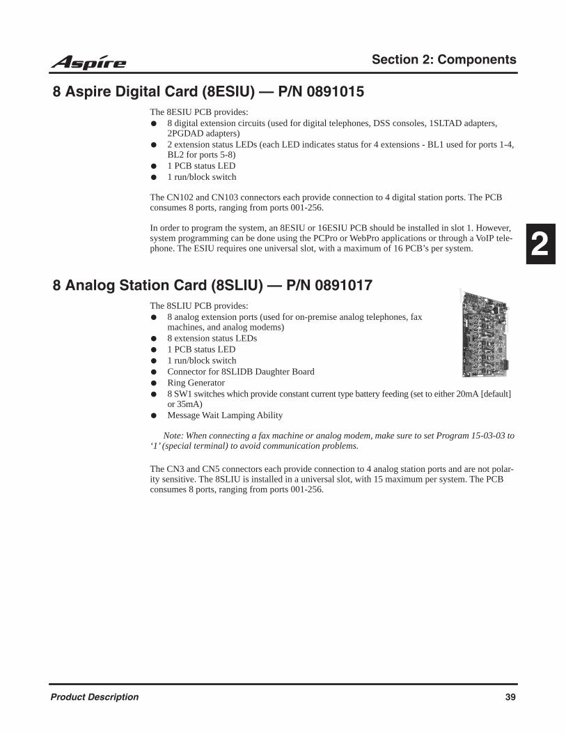
Section 2: Components
2
8 Aspire Digital Card (8ESIU) — P/N 0891015 The 8ESIU PCB provides: 8 digital extension circuits (used for digital telephones, DSS consoles, 1SLTAD adapters,
2PGDAD adapters) 2 extension status LEDs (each LED indicates status for 4 extensions - BL1 used for ports 1-4,
BL2 for ports 5-8) 1 PCB status LED 1 run/block switch
The CN102 and CN103 connectors each provide connection to 4 digital station ports. The PCB consumes 8 ports, ranging from ports 001-256.
In order to program the system, an 8ESIU or 16ESIU PCB should be installed in slot 1. However, system programming can be done using the PCPro or WebPro applications or through a VoIP tele-phone. The ESIU requires one universal slot, with a maximum of 16 PCB’s per system.
8 Analog Station Card (8SLIU) — P/N 0891017The 8SLIU PCB provides: 8 analog extension ports (used for on-premise analog telephones, fax
machines, and analog modems) 8 extension status LEDs 1 PCB status LED 1 run/block switch Connector for 8SLIDB Daughter Board Ring Generator 8 SW1 switches which provide constant current type battery feeding (set to either 20mA [default]
or 35mA) Message Wait Lamping Ability
Note: When connecting a fax machine or analog modem, make sure to set Program 15-03-03 to ‘1’ (special terminal) to avoid communication problems.
The CN3 and CN5 connectors each provide connection to 4 analog station ports and are not polar-ity sensitive. The 8SLIU is installed in a universal slot, with 15 maximum per system. The PCB consumes 8 ports, ranging from ports 001-256.
Product Description 39

Section 2: Components
8 Analog Station Expansion Daughter Board (8SLIDB) — P/N 0891018The 8SLIDB daughter board provides: 8 analog extension ports (used for on-premise analog telephones, fax
machines, and analog modems) 8 SW1 switches which provide constant current type battery feeding (set to
either 20mA [default] or 35mA) Connector for 8SLIU PCB Ring Generator Message Wait Lamping Ability
Note: When connecting a fax machine or analog modem, make sure to set Program 15-03-03 to ‘1’ (special terminal) to avoid communication problems.
The CN3 and CN5 connectors each provide connection to 4 analog station ports and are not polar-ity sensitive. The 8SLIDB is installed on the 8SLIU PCB, with 15 maximum per system. The daughter board consumes 8 ports, ranging from ports 001-256.
4 Aspire Wireless (DECT) Station PCB (4DSIU) — P/N 0891090The 4DSIU PCB provides the ability to use Aspire Wireless (DECT) phones with the Aspire system. Each 4DSIU PCB allows up to 4 base stations to be connected. Each RFP connector on the PCB pro-vides connection to 4 Base Stations, using 4 station ports (ranging from 002-512 if manually pro-grammed or 257-512 if automatically selected). As the Base Stations are powered by the DSIU PCB, whenever a DSIU PCB is installed in an Aspire cabinet, two power supplies must be installed. Only one DSIU PCB can be installed in a system with a maximum of 120 handsets connected. This PCB does not consume any ports - the ports are assigned as the telephones are registered to the system.
The maximum number of B-channels supported is 32, which means that the DSIU PCB (any ver-sion) can support a maximum of 32 conversations at one time.
8 Aspire Wireless (DECT) Station PCB (8DSIU) — P/N 0891091The 8DSIU PCB provides the ability to use Aspire Wireless (DECT) phones with the Aspire system. Each 8DSIU PCB allows up to 8 base stations to be connected. Each RFP connector on the PCB pro-vides connection to 4 Base Stations, using 4 station ports (ranging from 002-512 if manually pro-grammed or 257-512 if automatically selected). As the Base Stations are powered by the DSIU PCB, whenever a DSIU PCB is installed in an Aspire cabinet, two power supplies must be installed. Only one DSIU PCB can be installed in a system with a maximum of 120 handsets connected. This PCB does not consume any ports - the ports are assigned as the telephones are registered to the system.
The maximum number of B-channels supported is 32, which means that the DSIU PCB (any ver-sion) can support a maximum of 32 conversations at one time.
40 Product Description
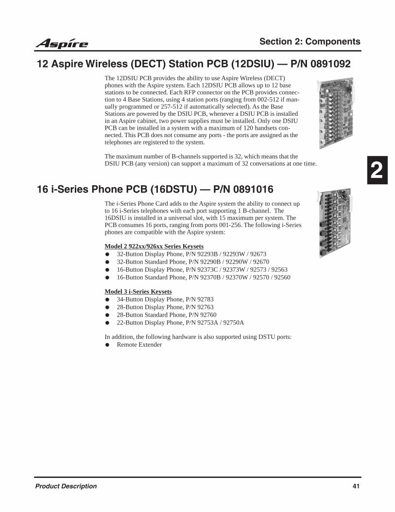
Section 2: Components
2
12 Aspire Wireless (DECT) Station PCB (12DSIU) — P/N 0891092The 12DSIU PCB provides the ability to use Aspire Wireless (DECT) phones with the Aspire system. Each 12DSIU PCB allows up to 12 base stations to be connected. Each RFP connector on the PCB provides connec-tion to 4 Base Stations, using 4 station ports (ranging from 002-512 if man-ually programmed or 257-512 if automatically selected). As the Base Stations are powered by the DSIU PCB, whenever a DSIU PCB is installed in an Aspire cabinet, two power supplies must be installed. Only one DSIU PCB can be installed in a system with a maximum of 120 handsets con-nected. This PCB does not consume any ports - the ports are assigned as the telephones are registered to the system.
The maximum number of B-channels supported is 32, which means that the DSIU PCB (any version) can support a maximum of 32 conversations at one time.
16 i-Series Phone PCB (16DSTU) — P/N 0891016The i-Series Phone Card adds to the Aspire system the ability to connect up to 16 i-Series telephones with each port supporting 1 B-channel. The 16DSIU is installed in a universal slot, with 15 maximum per system. The PCB consumes 16 ports, ranging from ports 001-256. The following i-Series phones are compatible with the Aspire system:
Model 2 922xx/926xx Series Keysets 32-Button Display Phone, P/N 92293B / 92293W / 92673 32-Button Standard Phone, P/N 92290B / 92290W / 92670 16-Button Display Phone, P/N 92373C / 92373W / 92573 / 92563 16-Button Standard Phone, P/N 92370B / 92370W / 92570 / 92560
Model 3 i-Series Keysets 34-Button Display Phone, P/N 92783 28-Button Display Phone, P/N 92763 28-Button Standard Phone, P/N 92760 22-Button Display Phone, P/N 92753A / 92750A
In addition, the following hardware is also supported using DSTU ports: Remote Extender
Product Description 41

Section 2: Components
The following i-Series hardware is NOT supported on the Aspire system:
When using i-Series phones on the Aspire system, the following features are NOT supported:
In addition to the above, the 92290x, 92670, 92370x, 92570, 92560, and 92760 phones do NOT support:
2OPX 3ACI 900/900i/910i Cordless Phone DCI-A/B DCI-L Digital VANGARD Voice Mail DSLT DSS Consoles VAU Analog Module Data Module Off-Hook Voice Announce Module Speakerphone Module Super Display Phones
Directory Dial Super Display Operation Soft Keys Headset Key Changing Incoming CO and ICM Ring
Tones (Program 11-11-20) Telephone System Programming (#*#*)
Program 10-03 : PCB Setup (DSTU PCB has no programmable options)
Program 90-17-01 : Display Firmware Version
Program 90-07-01 : Extension Control
Check Abandon Calls (CHECK + CALL2) Check Port/Name (CHECK + CALL1) Name Program (Service Code 800) Language Display (Program 15-02-01) Time and Date Display Modes (Program
20-02-07)
42 Product Description
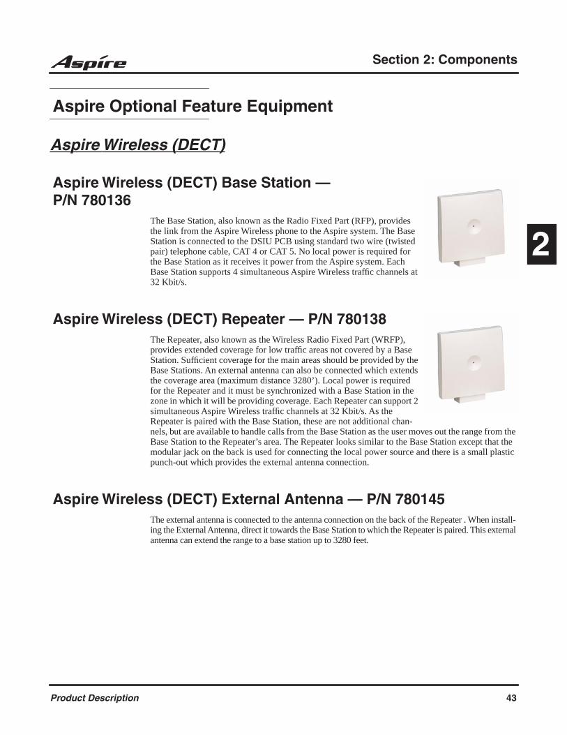
Section 2: Components
2
Aspire Optional Feature Equipment
Aspire Wireless (DECT)
Aspire Wireless (DECT) Base Station — P/N 780136
The Base Station, also known as the Radio Fixed Part (RFP), provides the link from the Aspire Wireless phone to the Aspire system. The Base Station is connected to the DSIU PCB using standard two wire (twisted pair) telephone cable, CAT 4 or CAT 5. No local power is required for the Base Station as it receives it power from the Aspire system. Each Base Station supports 4 simultaneous Aspire Wireless traffic channels at 32 Kbit/s.
Aspire Wireless (DECT) Repeater — P/N 780138The Repeater, also known as the Wireless Radio Fixed Part (WRFP), provides extended coverage for low traffic areas not covered by a Base Station. Sufficient coverage for the main areas should be provided by the Base Stations. An external antenna can also be connected which extends the coverage area (maximum distance 3280’). Local power is required for the Repeater and it must be synchronized with a Base Station in the zone in which it will be providing coverage. Each Repeater can support 2 simultaneous Aspire Wireless traffic channels at 32 Kbit/s. As the Repeater is paired with the Base Station, these are not additional chan-nels, but are available to handle calls from the Base Station as the user moves out the range from the Base Station to the Repeater’s area. The Repeater looks similar to the Base Station except that the modular jack on the back is used for connecting the local power source and there is a small plastic punch-out which provides the external antenna connection.
Aspire Wireless (DECT) External Antenna — P/N 780145The external antenna is connected to the antenna connection on the back of the Repeater . When install-ing the External Antenna, direct it towards the Base Station to which the Repeater is paired. This external antenna can extend the range to a base station up to 3280 feet.
Product Description 43

Section 2: Components
Aspire Wireless (DECT) Deployment Kit — P/N 780146The Deployment Kit consists of two 2.4GHz Aspire Wireless handsets, a special base station, and connecting cables all packed into a handy hard-shell briefcase. Before installing the Aspire Wire-less equipment, the deployment and diagnostics tool can be used to find the best place for the Base Stations by measuring the area of coverage of a Base Station within the building. Proper placement for the equipment is required for complete Aspire Wireless phone coverage.
In a building which has multiple telephone systems installed, the Deployment Tool can see all the systems to determine if there are too may systems running (too much radio activity in the air). It can be set to find all current stations running, but it is possible, by making a selection of the RFPI num-ber, to search for a particular group of bases. If you wish to check the range of a particular base in a multi-base system, the Deployment Tool is able to lock onto the Base Station to avoid handover to any other units. You can also use the Deployment Tool to see channels with noise levels from -90 dBm to -60 dBm in jumps of 5 dBm.
Aspire Wireless (DECT) Repeater Programming Kit — P/N 780142The Repeater is synchronized with the Base Station using the Repeater Programming Kit. This kit provides a cable with an RS232 connection which is used to connect the Repeater to a PC. A Windows application is then used to define the Base Station with which the Repeater should be synchronized.
Aspire Wireless (DECT) Service Tool Kit — P/N 780143The Service Tool Kit contains a uniquely configured serial cable and a special charging unit. In addition to these items, the latest version of the Service Tool program is required. This can be downloaded from the Downloads page within the NEC Technical Support web site (http://ws.necii.com).
These items are used to set up special functions. When connected to a handset, the volume can be adjusted, the start-up text can be altered, new flash code and menus and be loaded, and the gain lev-els of the microphone and loudspeaker for the handset can be adjusted.
44 Product Description
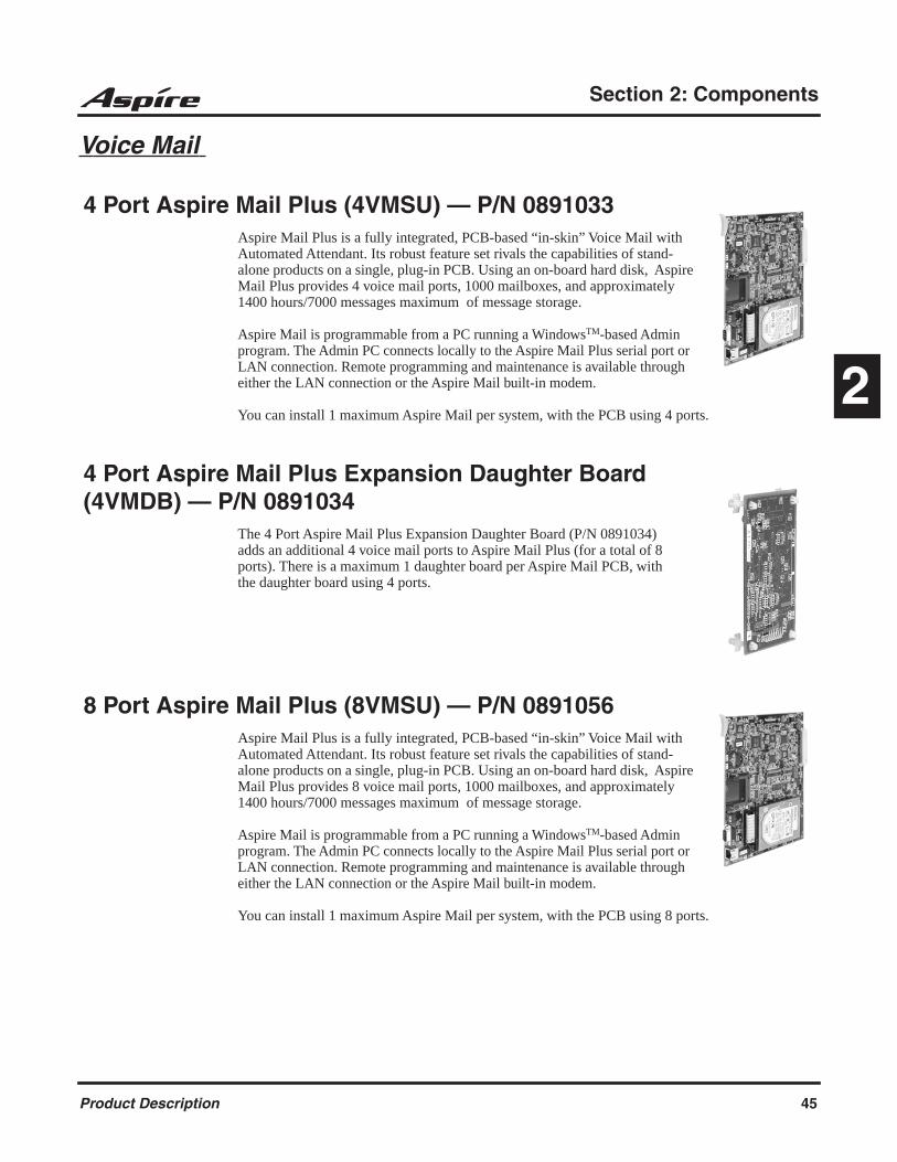
Section 2: Components
2
Voice Mail
4 Port Aspire Mail Plus (4VMSU) — P/N 0891033Aspire Mail Plus is a fully integrated, PCB-based “in-skin” Voice Mail with Automated Attendant. Its robust feature set rivals the capabilities of stand-alone products on a single, plug-in PCB. Using an on-board hard disk, Aspire Mail Plus provides 4 voice mail ports, 1000 mailboxes, and approximately 1400 hours/7000 messages maximum of message storage.
Aspire Mail is programmable from a PC running a WindowsTM-based Admin program. The Admin PC connects locally to the Aspire Mail Plus serial port or LAN connection. Remote programming and maintenance is available through either the LAN connection or the Aspire Mail built-in modem.
You can install 1 maximum Aspire Mail per system, with the PCB using 4 ports.
4 Port Aspire Mail Plus Expansion Daughter Board (4VMDB) — P/N 0891034
The 4 Port Aspire Mail Plus Expansion Daughter Board (P/N 0891034) adds an additional 4 voice mail ports to Aspire Mail Plus (for a total of 8 ports). There is a maximum 1 daughter board per Aspire Mail PCB, with the daughter board using 4 ports.
8 Port Aspire Mail Plus (8VMSU) — P/N 0891056Aspire Mail Plus is a fully integrated, PCB-based “in-skin” Voice Mail with Automated Attendant. Its robust feature set rivals the capabilities of stand-alone products on a single, plug-in PCB. Using an on-board hard disk, Aspire Mail Plus provides 8 voice mail ports, 1000 mailboxes, and approximately 1400 hours/7000 messages maximum of message storage.
Aspire Mail is programmable from a PC running a WindowsTM-based Admin program. The Admin PC connects locally to the Aspire Mail Plus serial port or LAN connection. Remote programming and maintenance is available through either the LAN connection or the Aspire Mail built-in modem.
You can install 1 maximum Aspire Mail per system, with the PCB using 8 ports.
Product Description 45
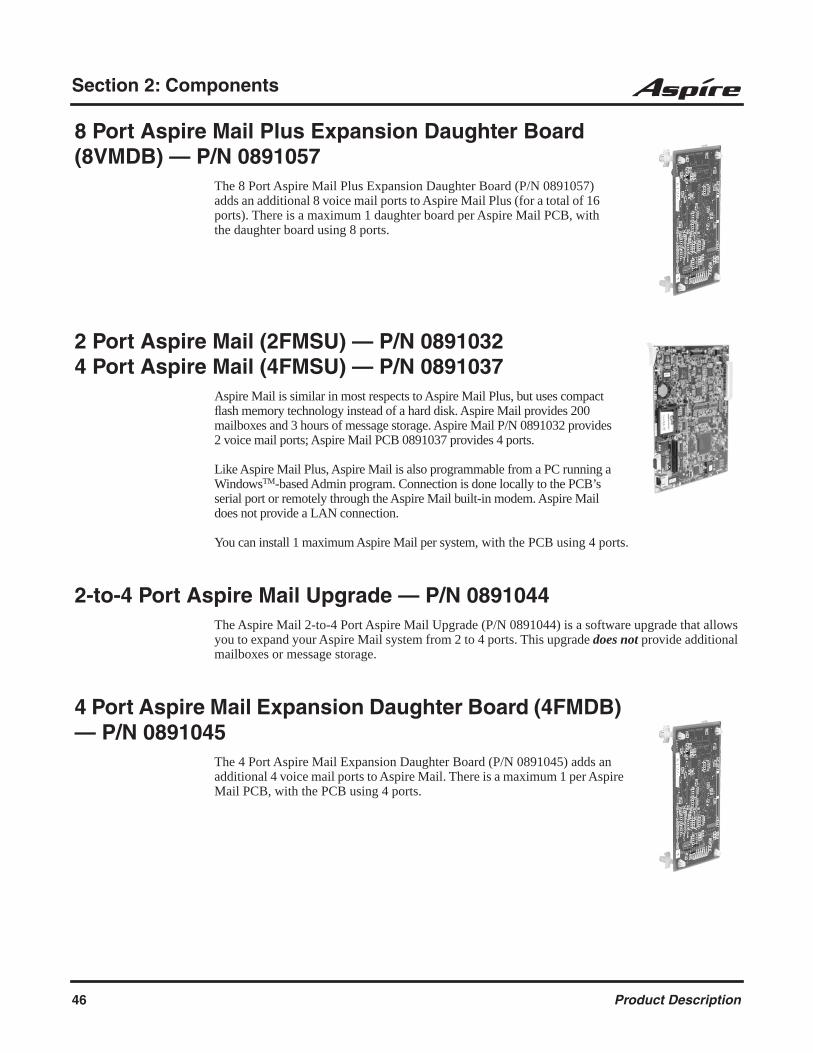
Section 2: Components
8 Port Aspire Mail Plus Expansion Daughter Board (8VMDB) — P/N 0891057
The 8 Port Aspire Mail Plus Expansion Daughter Board (P/N 0891057) adds an additional 8 voice mail ports to Aspire Mail Plus (for a total of 16 ports). There is a maximum 1 daughter board per Aspire Mail PCB, with the daughter board using 8 ports.
2 Port Aspire Mail (2FMSU) — P/N 08910324 Port Aspire Mail (4FMSU) — P/N 0891037
Aspire Mail is similar in most respects to Aspire Mail Plus, but uses compact flash memory technology instead of a hard disk. Aspire Mail provides 200 mailboxes and 3 hours of message storage. Aspire Mail P/N 0891032 provides 2 voice mail ports; Aspire Mail PCB 0891037 provides 4 ports.
Like Aspire Mail Plus, Aspire Mail is also programmable from a PC running a WindowsTM-based Admin program. Connection is done locally to the PCB’s serial port or remotely through the Aspire Mail built-in modem. Aspire Mail does not provide a LAN connection.
You can install 1 maximum Aspire Mail per system, with the PCB using 4 ports.
2-to-4 Port Aspire Mail Upgrade — P/N 0891044The Aspire Mail 2-to-4 Port Aspire Mail Upgrade (P/N 0891044) is a software upgrade that allows you to expand your Aspire Mail system from 2 to 4 ports. This upgrade does not provide additional mailboxes or message storage.
4 Port Aspire Mail Expansion Daughter Board (4FMDB) — P/N 0891045
The 4 Port Aspire Mail Expansion Daughter Board (P/N 0891045) adds an additional 4 voice mail ports to Aspire Mail. There is a maximum 1 per Aspire Mail PCB, with the PCB using 4 ports.
46 Product Description

Section 2: Components
2
IP Interface Cards VoIP PCB Installation Note:When installing a VoIP PCB, the system automatically assigns trunk ports to match the card’s port capacity. For example, a 4VOIPU would take 4 trunk ports, the 4VOIPU with a 4VOIPDB would take 8 trunk ports. Extension ports are not reserved until an IP phone is connected to the system. When the first IP phone is plugged in, the system takes the next four consecutive extension ports available and automatically assigns them as IP ports. The next three IP phones installed will use this group of ports. When the fifth IP phone is connected, the next 4 consecutive extension ports avail-able will be assigned as IP ports.
If the number of trunk ports reserved by the system is a concern, install the trunk cards first, then install the VOIPU PCB. This will allow the trunks to be assigned to the COIU, DIOPU, etc. first. If there are not enough trunk ports available for the VoIP PCB, the system will still recognize the card and allow it to be used for IP phones.
If the PCB is not going to be used for trunks, the logical trunk ports can be set to ‘0’ in Program 10-03-01 : PCB Setup, but the physical trunk ports are still assigned to the PCB and cannot be used for any other PCB unless the PCB is deleted from the slot in Program 90-05 : Slot Control.
The Aspire VoIP supports H.323, H.325, and H.245 trunks and compressions of G.711, G.723.1, and G.729.
4 CH VoIP Media Gateway (4VOIPU) — P/N 0891042The 4VoIP PCB is used for converting the RTP (Real Time Transfer Protocol) packets via the IP network and PCM highway. The IP telephones are connected directly to the IP bus. When IP phones need to be connected to a conventional PCM-based digital circuit, this PCB converts the IP packet signal into a PCM signal format and connects to the PCM time division switch.
The 4VOIPU PCB is required in order for IP telephones to communicate with non-VoIP Aspire phones, as well as to place or receive outside calls. This PCB can be used with either the Basic or Enhanced version of the NTCPU (P/N’s 0891002 and 0891038).
The 4VOIPU PCB provides: 4VOIPU PCB provides up to 4 channels Connector for the VOIPDB daughter board (providing an additional 4 channels) 1 PCB status LED 1 run/block switch
A maximum of 16 PCBs per system are allowed, providing 64 channels (with the daughter board, 128 channels) and it can be plugged into any universal slot. The PCB will consume 4 extension ports and, if available, 4 trunk ports.
If a separate software hub is used (and not the 8SHUBU PCB), it should be a 100Base/full duplex hub. To avoid network problems and to ensure good voice quality, do not use a Repeater Hub/10Base.
Product Description 47

Section 2: Components
4 CH VoIP Media Gateway Expansion Daughter Board (4VOIPDB) — P/N 0891043
The VOIPDB daughter board provides: 4 channels Connector for the 4VOIPU PCB (combination provides a maximum of 8 channels per slot)
The VOIPDB is installed on the 4VOIPU PCB with a maximum of 16 daughter boards per system, providing 128 channels (when combining the 4VOIPU and VOIPDB). The daughter board will consume 4 extension ports and, if available, 4 trunk ports. This PCB can be used with either the Basic or Enhanced version of the NTCPU (P/N’s 0891002 and 0891038).
16 CH VoIP Media Gateway (16VOIPU) — P/N 0891022The 16VoIP PCB is used for converting the RTP (Real Time Transfer Pro-tocol) packets via the IP network and PCM highway. The IP telephones are connected directly to the IP bus. When IP phones need to be connected to a conventional PCM-based digital circuit, this PCB converts the IP packet signal into a PCM signal format and connects to the PCM time division switch.
The 16VOIPU PCB is required in order for IP telephones to communicate with non-VoIP Aspire phones, as well as to place or receive outside calls.
The 16VOIPU PCB provides: 16VOIPU PCB provides up to 16 channels Connector for the VOIPDB daughter board (providing an additional 16 channels) 1 PCB status LED 1 run/block switch
A maximum of 16 PCBs per system are allowed, providing 256 channels (with the daughter board, 512 channels) and it can be plugged into any universal slot. The PCB will consume 16 extension ports and, if available, 16 trunk ports.
If a separate software hub is used (and not the 8SHUBU PCB), it should be a 100Base/full duplex hub. To avoid network problems and to ensure good voice quality, do not use a Repeater Hub/10Base.
48 Product Description

Section 2: Components
2
16 CH VoIP Media Gateway Expansion Daughter Board (16VOIPDB) — P/N 0891023
The 16VOIPDB daughter board provides:
16 channels Connector for the 16VOIPU PCB (combination provides a maxi-
mum of 32 channels per slot)
The VOIPDB is installed on the 16VOIPU PCB with a maximum of 16 daughter boards per system, providing 512 channels (when combining the 16VOIPU and VOIPDB). The PCB will consume 16 extension ports and, if available, 16 trunk ports.
10/100BaseT 8-Port Switching Hub (8SHUBU) — P/N 0891021The LAN PCB is an 8-port switching hub which complies with the ethernet specification for both 100Base-TX and 10Base-T. This PCB is compatible in LAN applications using 10Mbps and 100Mbps. All ports will automati-cally identify and switch 100Base-TX, 10Base-T and Full/Half Duplex.
The 4VOIPU or 16VOIPU PCB, which is required in order for IP tele-phones to communicate with non-VoIP Aspire phones, as well as to place or receive outside calls, must be connected to either an external switching hub or to the 8SHUBU PCB.
The PCB plugs into a universal slot, with a maximum of 8 PCBs per sys-tem. No ports are consumed with the installation of this PCB. Each PCB provides 8 RJ45 port connectors. These are used to connect to LAN terminals. Depending on the type of LAN terminal, the PCB may not be able to detect the difference between straight cable and cross-cable automatically. If auto-crossover is not functioning, use straight cable for that terminal connection.
Product Description 49

Section 2: Components
IP Station Equipment
34B Aspire IPhone - BK — P/N 0890065This keyset provides a network connector which allows it to be used with the VoIP feature.
The 34-Button Aspire IPhone has a 3-line, 24-character display with four interactive soft keys for intuitive feature access. In addition, it has 24 user-programmable function keys (with Dual LEDs) for one-button access to co-workers, features and outside lines. The telephone also provides 10 user-programmable One-Touch (Personal Speed Dial) keys and 15 additional fixed feature keys.
The 34-Button Aspire IPhone has a built-in speakerphone and can accept optional IP adapters (PSA, ADA2). You can also assign 110-Button DSS Consoles to these phones, but they must be on site (not networked). It provides Handsfree Answerback, Intercom voice-announcements. In addi-tion, the telephone provides a built-in wall-mount bracket, as well as adjustable legs which allow each phone to be angled at a height which best suits the user.
H.323 IP Phone — P/N 780005This UIP300 H.323 IP phone is a business IP phone in an enterprise LAN environment and will be connected to IP PBX systems via an RJ45 network cable.
Standard Telephone Features: Alphanumeric LCD display with 2 lines of 24 characters 10 LED indicators (Line 1 / Line 21 / Status / Mute / Speaker (Headset) / 5 Function keys) 12 Key Dial Pad 20 Specific Keys (5 Function keys, Menu, Select, Cancel/Del, Transfer, Mute, Redial, Hold,
Conference, Speaker, Line 1 and 2 keys, Volume Up and Down keys, Menu Up and Down keys)
Local Date and Time Call Duration Display Volume Control for Speaker, Handset, Headset, and Ringer Phone Book, Speed Dial, Dial from Call Logs (30 Outgoing Calls, 30 Incoming Calls and 15
Missed Calls) Redial, Hold2, Mute Call Waiting, Call Forward, Call Transfer, Do Not Disturb (DND) Display Caller ID (Name & Number) On-hook Dialing, Handsfree Talking (Full Duplex) DTMF Generation 8 Ringer Tones
This phone does not support the following: The phones cannot send digits after a call has been placed and before it is answered. This
means that features which use single digit service codes, such as Voice Over and Barge-In, are not available with this type of phone.
These phones do not provide P-codes, and therefore, cannot be used with the inDepth application. The Message Waiting/Voice Mail LED will not flash when there are new messages.
50 Product Description
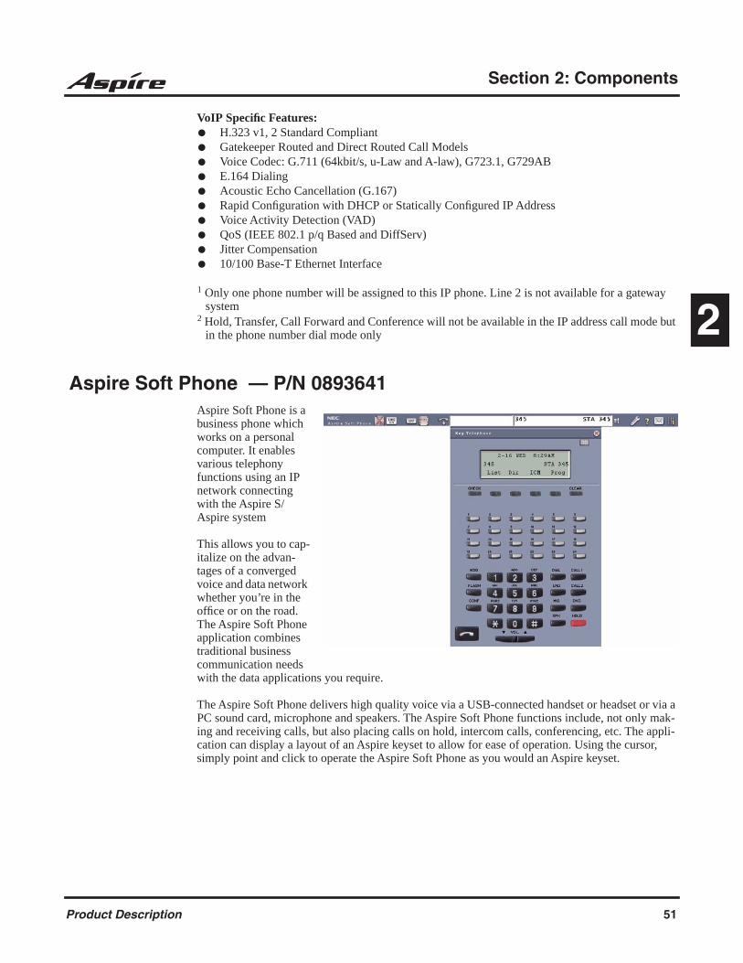
Section 2: Components
2
VoIP Specific Features: H.323 v1, 2 Standard Compliant Gatekeeper Routed and Direct Routed Call Models Voice Codec: G.711 (64kbit/s, u-Law and A-law), G723.1, G729AB E.164 Dialing Acoustic Echo Cancellation (G.167) Rapid Configuration with DHCP or Statically Configured IP Address Voice Activity Detection (VAD) QoS (IEEE 802.1 p/q Based and DiffServ) Jitter Compensation 10/100 Base-T Ethernet Interface
1 Only one phone number will be assigned to this IP phone. Line 2 is not available for a gateway system
2 Hold, Transfer, Call Forward and Conference will not be available in the IP address call mode but in the phone number dial mode only
Aspire Soft Phone — P/N 0893641Aspire Soft Phone is a business phone which works on a personal computer. It enables various telephony functions using an IP network connecting with the Aspire S/Aspire system
This allows you to cap-italize on the advan-tages of a converged voice and data network whether you’re in the office or on the road. The Aspire Soft Phone application combines traditional business communication needs with the data applications you require.
The Aspire Soft Phone delivers high quality voice via a USB-connected handset or headset or via a PC sound card, microphone and speakers. The Aspire Soft Phone functions include, not only mak-ing and receiving calls, but also placing calls on hold, intercom calls, conferencing, etc. The appli-cation can display a layout of an Aspire keyset to allow for ease of operation. Using the cursor, simply point and click to operate the Aspire Soft Phone as you would an Aspire keyset.
Product Description 51
Section 2: Components
In-Line Power Adapter (ILPA-R) — P/N 780122The In-Line Power Adapter (ILPA-R), which is IEEE 802.3af compliant, detects power from a PoE-compatible ethernet switch and passes it to the IP terminal. The ILPA does the negotiation and detection with the switch and then relays the power to the IP terminal device. This provides an addi-tional way to power the NEC IP terminals (Aspire IPhone or Aspire Keyset with IP Adapter). With this adapter, the IP terminals on the Aspire can be powered using: Local power connecting the IP terminal to a local AC wall outlet using the AC-2R Adapter
(P/N 780135) NEC power supply PoE-managed switch (BlueFire 200/24) (in-line and spare pair detection) Aspire 8SHUBU PCB (P/N 0891021) (spare pair detection) Cisco Data Switch - CDP supported (in-line and spare pair detection) In-Line Power Adapter
Keep the following in mind when installing an ILPA: Only IP telephones supported by center feed can be used. This adapter can not be used with the H.323 telephones. When center feed is used, first unplug the adapter from the ethernet switch before changing the
SW1 setting on the back of the adapter. Please note that the ILPA-R adapter is intended for use with the Aspire IPhones (P/N 0890065)
and IP Adapters (P/N 0890060). Installing any other device into the telephone port of the ILPA-R may result in damage to the device.
When powering an IP phone using an ILPA-R adapter, the phone should not get connected to a port on the 8SHUBU PCB.
AC Adapter (AC-2R) — P/N 780135The AC Adapter is required for the IP adapter or Aspire IPhone if external power is needed. Also required for APR, CTU, and Speaker-phone optional keyset adapters.
52 Product Description
Section 3: Features
3
Section 3: Features
Abbreviated Dialing
DescriptionAbbreviated Dialing gives an extension user quick access to frequently called numbers. This saves time, for example, when calling a client with whom they deal often. Instead of dialing a long tele-phone number, the extension user just dials the Abbreviated Dialing code.
There are three types of Abbreviated Dialing: Common, Group and Personal. All co-workers can share the Common Abbreviated Dialing numbers. All co-worker’s in the same Abbreviated Dialing Group can share the Group Abbreviated Dialing numbers. Personal Abbreviated Dialing numbers are available only at a user’s own extension. To set up Personal Abbreviated Dialing, refer to the “One-Touch Calling” feature. The system has 2000 Abbreviated Dialing bins that you can allocate between Common and Group Abbreviated Dialing.
Each Abbreviated Dialing bin can store a number up to 24 digits long.
When placing an Abbreviated Dialing call, the system normally routes the call through Trunk Group Routing or ARS (whichever is enabled). Or, the user can preselect a specific trunk for the call. In addition, the system can optionally force Common Abbreviated Dialing numbers to route over a specific Trunk Group. User pre-selection always overrides the system routing.
Common Bins Limited to 1000 with Dial Key or #2 Service CodeThough there are 2000 Abbreviated Dialing bins available in the system, once programmed, these bins can currently only be dialed using the Directory Dial feature (Press Directory Dialing Soft Key + ABBc Soft Key + Use arrow keys to locate number or enter the Abbreviated Dial bin name + CALL or SPK to place call.)
The DIAL key and service code #2 operations are not available for any 4-digit Abbreviated Dial common bin number.
DSS Console ChainingDSS Console chaining allows an extension user with a DSS Console to chain to an Abbreviated Dialing number stored under a DSS Console key. The stored number dials out (chains) to the initial call. This can, for example, simplify dialing when calling a company with an Automated Attendant. You can program the bin for the company number under one DSS Console key (e.g., #200) and the client’s extension number under the other (e.g., #201). The DSS Console user presses the first key to call the company, waits for the Automated Attendant to answer, then presses the second key to call the client (extension 400). See Programming below for additional details.
The DSS Console user can also chain to an Abbreviated Dialing number dialed manually, from a Programmable Function Key or a One-Touch Key.
Aspire S Aspire M/L/XL
• Available.
• 2000 bins available (0000-1999) for Common and Group Abbreviated Dialing. Up to 8 Abbreviated Dial-ing Groups available.
• Available.
• 2000 bins available (0000-1999) for Common and Group Abbreviated Dialing. Up to 64 Abbreviated Dial-ing Groups available.
Product Description 53

Section 3: Features
Storing a FlashTo enhance compatibility with connected Centrex and PBX lines, an Abbreviated Dialing bin can have a stored Flash command. For example, storing 9 Flash 926 5400 will cause the system to dial 9, flash the line and then dial 926 5400. The Flash can be stored by the user from their telephone or by the system administrator during system programming.
Using a Programmable Function KeyTo streamline frequently-called numbers, an Abbreviated Dialing Programmable Function Key can also store an Abbreviated Dialing bin number. When the extension user presses the key, the phone automatically dials out the stored number. This provides true one-touch calling via a phone’s function keys.
Account Codes
DescriptionAccount Codes are user-dialed codes that help the system administrator categorize and/or restrict trunk calls. The system has three types of Account Codes:
Optional Account Codes Optional Account Codes allow a user to enter an Account Code while placing a trunk call or anytime while on a call. This type of Account Code is optional; the system does not require the user to enter it.
Forced Account CodesForced Account Codes require an extension user to enter an Account Code every time they place a trunk call. If the user doesn’t enter the code, the system prevents the call. As with Optional Account Codes, the extension user can elect to enter an Account Code for an incom-ing call. However, the system does not require it. Forced Account Codes does not block 1-800, 1-888 and emergency assistance (911) calls.
Once set up in system programming, you can enable Forced Account Codes on a trunk-by-trunk basis. In addition, Forced Account Codes can apply to all outside calls or just long dis-tance calls. Forced Account Codes for Toll Calls restricts calls according to the following chart:
Aspire S Aspire M/L/XL
• Available.
• Adjustable Forced Account Code interdigit timer requires software 2.65+.
• Available.
• Adjustable Forced Account Code interdigit timer requires software 2.65+.
54 Product Description

Section 3: Features
3
Timer Modified to Allow for Forced Account Code Interdigit TimerProgramming has been changed which will allow the adjustment of the interdigit timer used for Forced Account Codes. Previously, this was fixed at 3 seconds.Depending on your software, the system will use the time set in Program 21-01-04 : System Options for Outgoing Calls - Dial Tone Detection Time for the interval the system will wait for a user to enter a Forced Account Code. By default, this option is set to 5 (Entries: 0-64800 seconds).
Verified Account CodesWith Verified Account Codes, the system compares the Account Code the user dials to a list of up to 1000 pre-programmed codes. If the Account Code is in the list, the call goes through. If the code dialed is not in the list, the system prevents the call. Verified Account Codes can be from 3-16 digits long using the characters 0-9 and #. During programming, you can use “wild cards” to streamline entering codes into system memory. For example, the entry 123W lets users dial Verified Account Codes from 1230 through 1239.
Operator NotificationTo prevent Account Code abuse, the system can notify the operator each time an Account Code vio-lation occurs. This can happen if the user fails to enter an Account Code (if Forced) or enters a Veri-fied Account Code that is not in the list. The notification is an automatic Intercom call to the attendant and a “RESTRICT” message in the operator’s display. (If the attendant fails to enter a valid Account Code, the system drops the call.)
Account Codes for Incoming CallsThe system can control the ability of extension users to enter Account Codes for incoming calls. When this option is enabled, a user can dial * while on an incoming call, enter an Account Code, and then dial * to return to their caller. If the option is disabled, any digits the user dials after answering an incoming call outdial on the connected trunk.
Hiding Account CodesAccount Codes can be optionally hidden from a telephone’s display. This would prevent, for exam-ple, an unauthorized co-worker from obtaining a Verified Account Code by watching the display and making note of the digits that dial out. When hidden, the Account Code digits show as the character “*” on the telephone’s display.
Number of Digits Dialed If first digit is not 1 If first digit is 1
1-3 Not allowed Not allowed
4-7 Allowed - does not require Account Code
Allowed - requires Account Code
More than 71 Allowed - requires Account Code
Allowed - requires Account Code
800 and 888 Allowed - requires Account Code
Allowed - does not require Account Code
011 (International) Allowed - requires Account Code
N/A
911 Allowed - does not require Account Code
N/A
1 If you change the local call length in Toll Restriction, this value changes accordingly.
Product Description 55

Section 3: Features
Account Code CapacityAccount Codes print along with the other call data on the SMDR record after the call completes. Account Codes can be 1-16 digits in length using 0-9 and #. Verified Account Codes can be from 3-16 digits long.
Redialed Numbers Do Not Contain Account CodesWhen using the Last Number Redial, Save or Repeat Dial features, the system will not retain Account Code information. Any number redialed with these features, the user will need to reenter an Account Code.
Note:If a user enters *12345*203 926 5400*67890*, if the Last Number Redial feature is used, the sys-tem dials the number as 203 926 5400*67890*. The *67890* is not treated as an Account Code.
Alarm
DescriptionAlarm lets a keyset extension work like an Alarm clock. An extension user can have Alarm remind them of a meeting or an appointment. There are two types of Alarms:
Alarm 1 (sounds only once at the preset time)
Alarm 2 (sounds every day at the preset time)
Alphanumeric Display
DescriptionMultibutton display telephones have a 3-line, 24 character per line alphanumeric display that pro-vides various feature status messages. These messages help the display telephone user process calls, identify callers and customize features.
Aspire S Aspire M/L/XL
• Available. • Available.
Aspire S Aspire M/L/XL
• Available. • Available.
56 Product Description

Section 3: Features
3
Analog Communications Interface (ACI)
DescriptionThe Analog Communications Interface (ACI) feature uses a PGDAD module to provide two analog ports (with associated relays) for Music on Hold, External Paging or auxiliary devices such as tape recorders and loud bells. The system allows up to 48 PGDAD modules (when used for ACI ports), for a maximum of 96 analog ports. Each PGDAD module requires an unused port on an ESIU PCB.
Music on Hold You can connect up to two customer-provided Music on Hold music sources to a PGDAD module. This lets you add additional music sources if the external source on the NTCPU PCB or the internal source are not adequate. By using PGDAD modules, you could even have a dif-ferent music source for each trunk.
When the system switches the ACI analog port to a trunk on Hold, the PGDAD relay associ-ated with the ACI analog port closes. You can use this capability to switch on the music source, if desired.
Extension users can dial the ACI analog port extension number and listen to the connected music source. The PGDAD relay associated with the port closes when the call goes through.
For Music on Hold, connect the music source to the PGDAD module. Connect the music source control leads to the CTL (control relay) jack. Refer to the Hardware Manual for addi-tional details.
External Paging An ACI analog port can also be an External Page output. When connected to customer-pro-vided External Paging equipment, the ACI port provides External Paging independent of the Aspire NTCPU external paging input (the Aspire S CPU does not provide an external paging input). To use the External Paging, an extension user just dials the ACI analog port extension number and makes the announcement. The system broadcasts the announcement from the ACI analog port and simultaneously closes the associated PGDAD relay. You can use the relay closure to control the External Paging amplifier, if required.
This external paging zone is not included in external all call paging or combination paging (internal and external).
For External Paging, connect the Paging amplifier to the PGDAD jack. Connect the amplifier control leads to the CTL (control relay) jack. Refer to the Hardware Manual for additional details.
Aspire S Aspire M/L/XL
• Available - 8 ACI software ports (4 PGDAD modules max. when used for ACI ports) and 4 ACI Department Groups.
• Available - 96 ACI software ports (48 PGDAD modules max. when used for ACI ports) and 16 ACI Department Groups.
Product Description 57

Section 3: Features
Auxiliary Device Control The PGDAD module can control a customer-provided tape recorder. When an extension user dials the ACI analog port extension number, they can automatically start the recorder and acti-vate the record function. When the user hangs up, the recording stops and the tape recorder turns off. For tape recording, connect the tape recorder AUX input jack to the PGDAD jack. Connect the recorder control leads (if available) to the CTL (control relay) jack. Refer to the Hardware Manual for additional details.
By using Department Calling, you can arrange multiple tape recorders into a pool. When an extension user dials the Department Group pilot number, they reach the first available tape recorder in the pool.
The relays in the PGDAD module can optionally control customer-provided external ringers (loud bells) and buzzers. When an extension user dials the ACI analog port extension number, the associated PGDAD relay closes and activates the ringer. You could use this capability to control an emergency buzzer for a noisy machine shop floor, for example.
ACI Call RecordingACI Call Recording allows you to use a recording device connected to a PGDAD module to manually or automatically record calls. The recording device is typically a customer-provided tape recorder. You can set up ACI Call Recording to output to a single ACI port/recording device or to a pool of ACI ports/devices. With a single device, all calls are stored in a central-ized location. With a pool of devices, you’ll be sure to have a port available for recording - even in peak traffic periods. You can set up automatic recording on a per trunk or manually on a per extension basis.
When set up for manual recording, the user presses the ACI Conversation Record key (Service Code 851 + 69 + 0) to begin recording the call from that point. When set up for automatic recording, ACI Call Recording starts automatically as soon as the user places or answers their call. The system can be programed to record all incoming trunk calls which ring an extension. This includes the following trunk types:
Central Office calls programmed to ring the extension. Direct Inward Dialing (DID) Direct Inward Line (DIL) Direct Inward System Access (DISA) Tie lines
The system can also be programmed to record outgoing trunk calls, however, this is only pos-sible using E&M tie lines, PRI or BRI trunks.
ACI Call Recording is not available for intercom calls, transferred calls, or calls placed on hold and answered by an extension with Call Recording enabled. To manually record any type of call (transferred, ICM, outgoing CO trunk, etc.), use the Voice Mail Conversation Record key (Service Code 851 + 78).
Physical Ports and Software PortsEach PGDAD module consists of a physical port for connection to the phone system and two logical ports. For programming purposes, the ports are also called software ports. The physical port connects to a station position on a EISU PCB. During installation, the first PGDAD module you set up is phys-ical port 1; the second PGDAD module is physical port 2, etc. Each PGDAD module has two soft-ware ports, which are numbered independently of the physical ports. Normally, the first PGDAD module set up has software ports 1-2; the second PGDAD module has software ports 3-4, etc. There are a total of 96 software ports (48 PGDAD modules x 2 ports each). During programming, you assign ACI extension numbers and Department Group options to PGDAD software ports, not physical ports. During installation, you connect equipment to the jacks on the PGDAD module that correspond to the software port. Refer to the system Hardware Manual for more installation details.
58 Product Description
Section 3: Features
3
Aspire Wireless
DescriptionThe Aspire system provides the ability to use 2.4 GHz Aspire Wireless/DECT (Digital Enhanced Cordless Telecommunication) phones. These phones provide you with the freedom and conve-niences of a wireless phone, but in addition, you also have access to features provided by the Aspire system.
The Aspire Wireless (DECT) phone provides additional options as well. Refer to the user guide included with your phone for details on these features.
12 Character Alphanumeric Display with Back Light LED Indication for Incoming and Unanswered Calls Telephone Book with 80 Number Memory Capacity Vibration Auto Log-In (roaming between different systems) 14 Messages Stored Stack for 10 Caller ID Silent Mode (mute all sounds) Redial (last 10 numbers) Programming Pause Programming of 2 Different Setups (indoor and outdoor) Adjustable Volume Key Lock 9 Different Ring Tones and Adjustable Ring Volume Microphone Mute Headset Connection Automatic Off-Hook (B-Answer) R-Key for Transfer and Special Services Detects other wireless devices and will temporarily block that frequency range until it becomes available (helps to prevent interference between devices)
Out-of-RangeWhen a Aspire Wireless phone receives an incoming call and the phone is considered out-of-range (Program 20-22-05 timer expires), what the system does with the call and what the caller hears depends on system programming.
Extension callers will hear a lock-out tone and may see “Out of Range” on their display. DISA callers will following the programming set in Program 25-04-01 : VRS/DISA Transfer
Ring Group With No Answer/Busy.
Aspire S Aspire M/L/XL
• Not Available. • Available with software 2.16+ - 120 phones maximum.
• Program options to adjust transmit and receive level of Aspire Wireless available with 2.63+ software.
• Service Codes for registering/unregistering Aspire Wire-less phones available with 2.63+ software.
Product Description 59
Section 3: Features
DID and DIL callers hear ringing and can then be transferred to voice mail or to another extension based on the settings in Program 15-15-05 and 15-15-06.
Tie line callers will hear the lock-out tone.
The Aspire Wireless requires the following hardware:
4-Port Interface PCB (P/N 0891090), 8-Port Interface PCB (P/N 0891091), or 12-Port Inter-face PCB (P/N 0891092)
Handset with Battery (P/N 780004)
Base Station (P/N 780136)
Charging Cradle (P/N 780137)
Optional Equipment: Leather Cover w/Clip for Aspire Wireless (DECT) Handset (P/N 780148)
Repeater (P/N 780138)
AC Adapter (P/N 780139)
Battery (NMh) (P/N 780140)
Handset Belt Clip (P/N 780141)
Repeater Programming Kit (P/N 780142)
Service Tool Kit (P/N 780143)
Deployment Tool (P/N 780144)
External Antenna w/Cable for Repeater (P/N 780145)
Prior to deleting an Aspire Wireless (DECT) phone from the system using Program 91-07-01 : DECT Subscription - Delete, make sure the DSIU PCB is installed in the system. If the DSIU is removed when Program 91-07-01 is run, the system will retain the DECT setting. This will prevent the Aspire Wireless phone(s) from being registered in the system again.
Programs Available for Gain AdjustmentWith software 2.63 or higher, you can adjust the gain of the Aspire Wireless handsets using Pro-gram 15-15-07 and 15-15-08.
Register/Unregister Handset by Service CodeThe Aspire Wireless telephones can be registered or unregistered at a display keyset using a service code. Note the following conditions when using this feature:
As this feature uses extension numbers and not port number, it is not possible to have the sys-tem select an available port as when using Program 91-06-01.
This feature only supports the wild card subscription method. It is not possible to specify the IPEI number.
The wait timer for terminal registration is fixed at 600 seconds.
This feature can only be used from a display keyset. Digital single line telephones and i-Series phones cannot be used.
This option is not available for Networked systems.
60 Product Description

Section 3: Features
3
Attendant Call Queuing
DescriptionAttendant extensions can have up to 32 incoming calls queued before additional callers hear busy tone. This helps minimize call congestion in systems that use the attendant as the overflow destina-tion for unanswered calls. For example, you can program Direct Inward Lines and Voice Mail calls to route to the attendant when their primary destination is busy. With Attendant Call Queuing, these unanswered calls would normally “stack up” for the attendant until they can be processed.
The 32 call queue total includes Intercom, DISA, DID, DIL, tie line and transferred calls. If the attendant doesn’t have an appearance for the queued call, it waits in line on a CALL key. If the attendant has more than 32 calls queued, an extension can Transfer a call to the attendant only if they have Busy Transfer enabled.
Attendant Call Queuing is a permanent, non-programmable system feature.
Automatic Call Distribution (ACD)
Aspire S Aspire M/L/XL
• Available. • Available.
Aspire S Aspire M/L/XL
• Not Available. • Available with the Basic NTCPU (P/N 0891002) with the PAL upgrade or the Enhanced NTCPU (P/N 0891038) - 64 ACD Groups and 512 ACD Agents.
• ACD Call Coverage keys supported with 1.06+ software.
• ACD Queue Status Display supported with 1.11+ software.
• ACD Hotline Key Shows Agent Status supported with 1.11+ software.
• ACD MIS software can count overflow calls with 2.63+ software.
• P Command Support for AIC Login available with 4.0E+ software. Note: This feature is not yet supported by the inDepth software.
• For more information, refer to the ACD Manual (P/N 0893202).
Product Description 61

Section 3: Features
Description Automatic Call Distribution (ACD) uniformly distributes calls among member agents of a pro-grammed ACD Group. When a call rings into an ACD Group, the system automatically routes the call to the agent that has been idle the longest. Automatic Call Distribution is much more sophisti-cated and comprehensive than Department Calling and other group services - it can accurately judge the work load at each agent and distribute calls accordingly. The system allows up to 64 ACD Groups and 512 ACD agents.
You can put any agent in any group. In addition, an agent can be in more than one group. This allows, for example, a Technical Service representation to answer Customer Service calls at lunch time when many of the Customer Service reps are unavailable.
The ACD Master Number is the “extension number” of the whole group. Calls directly ringing or transferred to the ACD Master number enter the group and are routed accordingly. Although the master number can be any valid extension number, you should choose a number that is out of the normal extension range.
Automatic Call Distribution operation is further enhanced by:
ACD Call Queuing When all agents in an ACD Group are unavailable, an incoming call will queue and cause the Queue Status Display to occur on the ACD Group Supervisor’s display. The display helps the supervisor keep track of the traffic load within their group. The Queue Status Displays shows: - The number of calls queued for an available agent in the group. - The trunk that has been waiting the longest, and how long it has been waiting.
For each ACD Group, you can set the following conditions: - The number of trunks that can wait in queue before the Queue Status Display occurs.- How often the time in queue portion of the display reoccurs.- If the supervisor should hear a Queue Alarm whenever the time in queue portion reoccurs. This alarm is a single beep tone that reminds the supervisor to check the condition of the queue.
ACD Overflow (With Announcements) ACD offers extensive overflow options for each ACD Group. For example, a caller ringing in when all agents are unavailable can hear an initial announcement (called the 1st Announce-ment). This announcement can be a general greeting like, “Thank you for calling. All of our agents are currently busy helping other customers. Please stay on the line and we will help you shortly.” If the caller continues to wait, you can have them hear another announcement (called the 2nd Announcement) such as, “Your business is important to us. Your call will be automatically answered by the first available agent. Please stay on the line.” If all the ACD Group’s agents still are unavailable, the call can automatically overflow to another ACD Group or the Voice Mail Automated Attendant. If all agents in the overflow ACD Group are busy, Lookback Routing automatically ensures that the waiting call will ring into the first agent in either group that becomes free.
You can assign an ACD Group with any combination of 1st Announcement, 2nd Announce-ment and overflow method. You can have, for example, a Technical Service group that plays only the 2nd Announcement to callers and then immediately overflows to Voice Mail. At the same time, you can have a Customer Service group that plays both announcements and does not overflow.
62 Product Description

Section 3: Features
3
Agent Log In and Log Out Services An ACD Agent can log in and log out of their ACD Group. While logged in, the agent is avail-able to receive ACD Group calls. When logged out, the agent is excluded from the group’s calls. The programmable keys and alphanumeric display on an agent’s phone show at a glance when they are logged in or logged out.
Agent Identity Code (AIC)An Agent Identity Code (AIC) allows ACD agents to log in any extension without setting Program 41-02 (AIC Log In). Using AIC, ACD agents can also log in to multiple ACD groups at the same time (up to 64 ACD Groups). The system will also allow all extensions (up to the system maxi-mum) to log in using the same AIC code. AIC and ACD groups for each work period (mode pat-tern number) can be set in Program 41-18.
Multiple Agent Log InACD agents can log their extension in using multiple AICs (up to 3). The system will also allow all extensions (up to the system maximum) to log in using the same AIC code. For example, even if ACD agent “A” logs in extension 350 with AIC 789, ACD agent “B” can also log in to extension 351 with AIC 789 at the same time.
In addition to an agent logging in with multiple AIC codes, ACD agents can log in to multiple ACD groups at the same time (up to 64 ACD Groups). AIC and ACD groups for each work period (mode pattern number) can be set in Program 41-18.
Some conditions with Multiple Agent Log In:
ACD agents cannot log in to the system supervisor or group supervisor’s extension. In order to log in with AIC, the extension should be set to AIC Log In mode in Program
41-17. If the extension is set to AIC log in mode in Program 41-17, the system will ignore the set-
ting of Program 41-02 for the extension. A supervisor cannot log out an agent logged in by an AIC code.
Emergency Call If an ACD Agent needs assistance with a caller, they can place an Emergency Call to their ACD Group Supervisor. Once the supervisor answers the Emergency Call, they automatically monitor both the ACD Agent and the caller. If the agent needs assistance, the supervisor can join in the conversation. Emergency Call can be a big help to inexperienced ACD Agents that need technical advise or assistance with a difficult caller. The supervisor can easily listen to the conversation and then “jump in” if the situation gets out of hand.
Enhanced DSS Operation A programmed extension user can use their DSS Console to monitor the status of the ACD Agents within a group. The DSS Console is an essential tool for supervisors. The console key flash rates tell the supervisor at a glance which of the group’s agents are: - Logged onto the group (i.e., in service) - Logged out of the group (i.e., out of service) - Busy on a call - Placing an Emergency Call to the supervisor - Not available or installed
The ACD Supervisor can also use their console for placing and transferring calls - just like any other extension user.
Product Description 63

Section 3: Features
Flexible Time Schedules An ACD Work Schedule lets you divide a day into segments (called Work Periods) for sched-uling the activity in your ACD Groups. You can set up four distinct Work Schedules, with up to eight Work Periods in each Work Schedule. Each day of the week has one Work Schedule, but different days can share the same schedule. For example, your Monday through Friday Work Schedule could consist of only two Work Periods. Work Period 1 could be from 8:00 AM to 5:00 PM - when your business is open. Work Period 2 could be from 5:00 PM to 8:00 AM - which covers those times when your business is closed.
Headset Operation (With Automatic Answer)An ACD Agent or ACD Group Supervisor can utilize a customer-provided headset in place of the handset. The headset conveniently frees up the user’s hands for other work and provides privacy while on the call. In addition, an ACD Agent with a headset can have Automatic Answer. This allows an agent busy on a call to automatically connect to the next waiting call when they hang up.
Incoming Call Routing Incoming trunk calls can automatically route to specific ACD Groups. These types of calls ring directly into the ACD Group without being transferred by a co-worker or the Automated Attendant.
Rest Mode Rest Mode temporarily logs-out an ACD agent’s phone. There are two types of Rest Mode:- - Manual Rest Mode
An ACD Agent can enable Manual Rest Mode anytime they want to temporarily log out of the ACD Group. They might want to do this if they go to a meeting or get called away from their work area. While logged out, calls to the ACD Group will not ring the agent’s phone.
- Automatic Rest Mode When an ACD Group has Automatic Rest Mode, the system will automatically put an agent’s phone in Rest Mode if it is not answered. This ensures callers won’t have to wait while ACD rings an extension that won’t be answered. For keysets, the system enables Automatic Rest Mode for all phones with Rest Mode keys. For SLTs, you must set an option in programming to enable Automatic Rest Mode. If an agent’s phone is placed into Rest Mode because a call is not answered, the agent will need to manually cancel Rest Mode in order to log back into the ACD group.
With a Rest Mode key programmed on an ACD agent’s phone, when the agent is in rest mode, the key will be lit. If the Rest Mode key is pressed while an agent is on a call, the key will flash to indicate a pre-Rest Mode status. When the current call is finished, the agent’s phone will be in rest mode. The agent can place intercom calls or receive direct incoming calls while in Rest Mode. The ability to receive incoming intercom calls is defined in system programming for each ACD group. Note that an ACD System Supervisor cannot be placed in Rest Mode.
64 Product Description

Section 3: Features
3
Supervisor, ACD Group You can designate an extension in an ACD Group to be the group’s supervisor. Once assigned as an ACD Group Supervisor, the user can: - Take the entire ACD Group out of service. - Check the log out status of each agent after the group taken down. - Restore the ACD Group to service.
During programming, you can choose one of three modes of operation for each ACD Group supervisor: - Supervisor’s extension cannot receive calls to the ACD Group. - Supervisor’s extension can only receive ACD Group calls during overflow conditions. - Supervisor’s extension receives calls just like any other ACD Group agent (mode 2).
An ACD Group can have only one supervisor. In addition, an extension can be a supervisor for only one ACD Group.
Supervisor, ACD System You can designate an extension as an ACD System Supervisor. Once assigned as an ACD System Supervisor, the user can: - Take the all the system’s ACD Groups out of service simultaneously - Check the log out status of each agent after the groups are taken down. - Restore all the ACD Groups to service simultaneously.
The system can have only one ACD System Supervisor.
Work Time Work Time temporarily busies-out an ACD agent’s phone so they can work at their desk unin-terrupted. This gives the agent time to fill out important logs and records as soon as they are finished with their call. There are two types of Work Time:
- Manual Work Time
An ACD Agent can enable Manual Work Time any time they need to work at their desk undisturbed. You might prefer this Work Time mode if an agent only occasionally has to fill out follow-up paper work after they complete their call. When the agent is through catching up with their work, they manually return themselves to the ACD Group.
- Automatic Work Time
The system implements Automatic Work Time for the agent as soon as they hang up their current call. This is helpful in applications (such as Tech Service groups) where follow-up paperwork is a requirement for every call. When the agent is done with their work, they manually return themselves to the ACD Group.
- ACD Group Call Coverage Keys To help cover calls during peak periods, a keyset can have Call Coverage keys for ACD Groups by assigning the ACD master number to the Call Coverage key. When a call rings into a covered ACD Group, it rings the appropriate ACD Group Call Coverage key, allow-ing users to pick up incoming ACD calls. The key can ring immediately, after a delay or just flash. The Call Coverage key also facilitates one-button Transfer for an ACD Group. The covering extension does not have to be a member of the ACD Group.
- Hotline Key Shows Agent Status An extension’s Hotline keys provide the “normal” Busy Lamp Field (BLF) for co-workers and a unique BLF for ACD Agents. Similarly to the supervisor’s DSS Console BLF, the unique BLF shows when the covered agent is in service, out of service or busy on a call. This enhanced BLF gives a department manager, for example, ACD Group monitoring capabilities without having to become a supervisor with a DSS Console.
Product Description 65
Section 3: Features
Hotline gives a keyset user one-button calling and Transfer to another extension (the Hot-line partner). Hotline helps co-workers that work closely together. The Hotline partners can call or Transfer calls to each other just by pressing a single key. Enhanced for ACD applications, Hotline provides a unique Busy Lamp Field for ACD agents as well as a BLF for co-workers that are not ACD agents.
- Enhanced Supervisor Options
An ACD supervisor can individually assign extensions to ACD Groups, and set an agent’s status once assigned. This provides the supervisor with tremendous flexibility to reassign agents as work loads vary.
- Queue Status Display with Scrolling
When all agents in an ACD Group are unavailable, an incoming call will queue and cause the Queue Status Display to occur on the ACD Group Supervisor and/or agent’s display (based on the Class of Service). The display helps the supervisor keep track of the traffic load within their group. In addition, any display keyset can have a Queue Status Display Check programmable function key. The keyset user can press this key any time while idle, and using the VOL and VOL , scroll through the Queue Status Displays of all the ACD Groups. The Queue Status Displays shows:
The number of calls queued for an available agent in the group. The trunk that has been waiting the longest, and how long it has been waiting.
For each ACD Group, you can set the following conditions:
The number of trunks that can wait in queue before the Queue Status Display occurs. How often the time in queue portion of the display reoccurs. Queue Status Display holding time. Queue Status Alarm enable/disable. Queue Status Alarm sending time.
When Logged Out of ACD GroupWhen ACD agents are logged out and a call is placed into the ACD queue, the phones of the logged out agents will display the Queue Status and hear the alarm according to the settings defined in system programming. Pressing the Queue Status Display Programma-ble Function key will return the phone to idle until the timer in Program 41-20-03 expires again.
- Overflow Announcements from Voice Mail The NVM-Series Voice Mail system can provide the ACD overflow announcements in systems that do not have a DSP daughter board installed for VRS. When a caller queues for an available agent, designated Voice Mail ACD Announcement Mailboxes provide the overflow messages.
- Escape from Queue with NVM-Series
Escape From Queue uses NVM-Series Call Routing Mailboxes for announcement mes-sages to provide callers with enhanced options while in queue. After listening to this type of announcement, they can either wait in queue or dial a digit for an alternate destination. The destination is typically the operator, a mailbox or an extension.
- Programmable Wrap-up Timer
When an agent finishes their call, the system automatically starts a wrap-up timer and blocks any ACD calls to the agent. This gives them time to complete important logs and records before a new call comes in. When the timer expires, the system returns the agent to the ACD Group to handle new callers.
66 Product Description

Section 3: Features
3
- InDepth and inDepth+InDepth and inDepth+ are Windows-based Management Information Systems that work with the system’s built-in ACD. These ACD/MIS systems enhance the system with real time statistics and reports on ACD Group traffic patterns and usage. Refer to the inDepth and inDepth+ feature for more details.
ACD Group as Overflow DestinationThe system can transfer an overflow call to a specific ACD Group or to voice mail using Program 41-09. When Program 41-08-02 : ACD Overflow Destination has the ACD Overflow Destination set to '65', the system will overflow the call to the ACD Group programmed in Program 41-09. (The system will not allow you to program an ACD group with that ACD group as the overflow.) If, while the call is ringing, the extension to which the call was transferred becomes available, both the extension and the overflow ACD group will ring.
Option Available for Counting Overflow Calls in ACD MIS SoftwareAn option is available for use with ACD MIS (such as inDepth/inDepth+) software to count over-flow calls. When the number of queued ACD overflow calls exceeds the limit and a busy tone is sent to the caller, the system programming will determine if the call is counted in the ACD MIS software.
P Command Support Added for AIC LoginThis feature is not yet supported by the inDepth software.
Previously, the Aspire P Commands would not support AIC log on/ log off. Because of this, it was not possible for the inDepth MIS software to determine which ACD groups each extension was a member of or to which ACD groups calls were presented.
With this software, AIC log on/log off operations are supported. The Aspire P Commands will indi-cate which ACD Group is being logged onto when an AIC code is entered. Also when an agent logs off, there will be a multiple log of events, one log off event for each previous ACD log on event.
For more on Automatic Call Distribution, refer to the ACD Manual (P/N 0893202).
Automatic Route Selection
Description Automatic Route Selection (ARS) provides call routing and call restriction based on the digits a user dials. ARS gives the system the most cost-effective use of the connected long distance carriers.
Aspire S Aspire M/L/XL
• Available.
• COS option for outgoing calls following access map is available.
• COS Matching feature is available with 2.63+ software.
• Alternate Carrier Access for ISDN trunks requires soft-ware 2.63+
• Available.
• COS option for outgoing calls following access map is available in software 1.11+.
• COS Matching feature is available with 2.63+ software.
• Alternate Carrier Access for ISDN trunks requires soft-ware 2.63+.
Product Description 67
Section 3: Features
ARS is an on-line call routing program that you can customize (like other system options) from a display telephone. ARS accommodates 250 call routing choices - without a custom-ordered rate structure database. With ARS, you can modify the system’s routing choices quickly and easily. This is often necessary in today’s telecommunications world where the cost structure and service choices frequently change.
The ARS feature can add or delete digits and route calls according to pre-determined levels. When Aspire systems are networked together by a tie line, the networked systems can be called by a sys-tem number and a user’s extension number, just an extension number, or by using a trunk access code.
ARS Feature SummaryARS provides:
Call RoutingARS can apply up to 24-digit analysis to every number dialed. For programming, ARS pro-vides separate 8-digit and 24-digit tables. Each table can have up to 250 numbers.
Dialing Translation (Special Dialing Instructions) ARS can automatically execute stored dialing instructions (called Dial Treatments) when it chooses a route for a call. The system allows up to 15 Dial Treatments. The Dial Treatments can:
- Automatically insert or delete a leading 1 - Insert or delete an area code (NPA) - Add digits (such as a dial-up OCC number), pauses and waits to the dialing sequence
Time of Day Selection For routing purposes, ARS provides ten different day selections (called Time Schedule Pat-terns). Each Time Schedule Pattern can provide up to 20 time intervals which are assigned to one of the eight day/night modes. The Time Schedule Patterns are then assigned to a day of the week (Monday-Friday, Saturday, Sunday or Holiday).
Basic ARS OperationWhen a user places an outside call, ARS analyzes the digits dialed and assigns one of 64 Selection Numbers to the call. The Selection Number chosen depends on which digits the user dialed. ARS then checks the time of day, the day of week and the extension’s ARS Class of Service. Based on these call routing options, ARS selects a trunk group for the call and imposes the Dial Treatment instructions (if any).
Class of Service Option Allows Outgoing Calls to Not Follow Access MapUsing this option allows an extension’s Class of Service to be set so that ARS does not follow the trunk access map settings (Program 14-07-01 and 15-06-01). The feature allows an extension user to have CO line keys on their phone which allow incoming access only. The user would only have outgoing access on the CO lines when using ARS to place a call.
Class of Service MatchingWith the ARS Class of Service Match Access feature, you can determine whether the system should allow a call based on the COS assigned to the Dial Analysis Table (Program 26-02). This change can be used to create a tenant-like application. It will then use the trunk group defined in the Addi-tional Entry in Program 26-02-03 to place the outgoing call.
When this feature is enabled, the calls will be routed in sequential order, and will forward provided the Class of Service for the trunk groups match.For this feature a new system option, Program 26-01-06 : Automatic Route Selection Service, COS Match Access, is added. In adding this feature, the ARS table is expanded from 200 to 400. First 200 entries will be compatible with the previous software as well as the 2.63 software.
68 Product Description

Section 3: Features
3
Alternate Carrier Access Added for ISDN TrunksAn option is available which allows the system to provide a Transit Network Selection information element for ARS calls using ISDN trunks. This information element identifies a requested transit network. This function is valid only for outbound calls by ISDN trunk.
Local calls do not need Network Selection information since they will be handled by the local exchange carrier (ILEC). If this is the case, ARS is able to distinguish between local and long dis-tance calls and add the Transit Network Selection information element when required.
This option would apply to both PRI and BRI ISDN trunks. If the trunk in the used in Program 26-02 : Dial Analysis Table for ARS/LCR is not an ISDN trunk, this code in the dial treatment will be ignored.
Background Music
DescriptionBackground Music (BGM) sends music from a customer-provided music source to speakers in key-sets. If an extension user activates it, BGM plays whenever the user’s extension is idle.
Barge In
DescriptionBarge In permits an extension user to break into another extension user’s established call, including Conference calls. This sets up a Conference-type conversation between the intruding extension and the parties on the initial call. With Barge In, an extension user can get a message through to a busy co-worker right away.
There are two Barge In modes: Monitor Mode (Silent Monitor) and Speech Mode. With Monitor Mode, the caller Barging In can listen to another user’s conversation but cannot participate. With Speech Mode, the caller Barging In can listen and join another user’s conversation.
Aspire S Aspire M/L/XL
• Available. • Available.
Aspire S Aspire M/L/XL
• Available. • Available.
CAUTION
UNAUTHORIZED INTRUSION ON CALLS USING THIS FEATURE MAY BE INTERPRETED AS AN INVASION OF PRIVACY.
Product Description 69

Section 3: Features
Call Coverage
Please refer to the Multiple Directory Numbers / Call Coverage (page 132) for information on this feature.
Call Duration Timer
DescriptionCall Duration Timer lets a keyset user time their trunk calls on the telephone display. This helps users that must keep track of their time on the phone. For incoming trunk calls, the Call Timer begins as soon as the user answers the call. For outgoing trunk calls, the Call Timer starts about 10 seconds after the user dials the last digit.
Call Forwarding
DescriptionCall Forwarding permits an extension user to redirect their calls to another extension. Call For-warding ensures that the user’s calls are covered when they are away from their work area. The types of Call Forwarding are:
Call Forwarding when Busy or Not AnsweredCalls to the extension forward when busy or not answered.
Call Forwarding ImmediateAll calls forward immediately to the destination, and only the destination rings.
Call Forwarding with Both RingingAll calls forward immediately to the destination, and both the destination and the forwarded extension ring (not for Voice Mail).
Call Forwarding when UnansweredCalls forward only if they are unanswered (Ring No Answer).
Aspire S Aspire M/L/XL
• Available.
• Program 20-09-06 requires software 2.67+.
• Available.
• Program 20-09-06 requires software 2.67+.
Aspire S Aspire M/L/XL
• Available.
• Activating Call Forwarding while on a call available with 2.63+ software.
• Available.
• Activating Call Forwarding while on a call available with 2.63+ software.
70 Product Description
Section 3: Features
3
Call Forwarding Follow MeRefer to Call Forwarding with Follow Me (page 73) for more.
Personal Answering Machine EmulationAllows the extension to emulate an answering machine. Refer to “Voice Mail” for more.
Call Forwarding will reroute calls ringing an extension, including calls transferred from another extension. The extension user must enable Call Forwarding from their phone. To redirect calls while a user is at another phone, use “Call Forwarding with Follow Me”. A periodic VRS announcement may remind users that their calls are forwarded.
Activating Call Forwarding While On a CallA keyset user can activate or deactivate Call Forwarding while on a call if the phone has a Call For-ward Programmable Function Key programmed (15-07-01 or SC: 851 16). Activating Call For-warding while on a call works only for Call Forward to Station key (Code: 16). Other Call Forward keys (Code: 10-15, 17) do not work while on a call. This option cannot be enabled while the user is hearing a confirmation or warning tone.
With older software, keyset user could only enable Call Forwarding when the phone was idle or when dial tone was heard.
This option is not available for single line telephones.
When Call Forward Follow Me is set up in a chain, forwarding cannot be canceled by the middle keyset while on a call.
Call Forwarding, Fixed
DescriptionFixed Call Forwarding is a type of forwarding that is permanently in force at an extension. Calls to an extension with Fixed Call Forwarding enabled automatically reroute - without any user action. Unlike normal Call Forwarding (which is turned on and off by extension users), Fixed Call For-warding is set by the administrator in system programming. Fixed Call Forwarding complements Voice Mail, for example. The administrator can program Fixed Call Forwarding to send a user’s unanswered calls to their Voice Mail mailbox. Each individual user no longer has to manually set this operation.
In system programming, the administrator can set the Fixed Call Forwarding destination and type for each extension and virtual extension. The forwarding destination can be an on- or off-premise extension or Voice Mail. The Fixed Call Forwarding types are:
Fixed Call Forwarding with Both Ringing (Program 24-06 Option 1)
Fixed Call Forwarding when Unanswered (Program 24-06 Option 2)
Fixed Call Forwarding Immediate (Program 24-06 Option 3)
Fixed Call Forwarding when Busy or Unanswered (Program 24-06 Option 4)
Fixed Call Forwarding Off-Premise (Program 24-07)
Aspire S Aspire M/L/XL
• Available. • Available.
Product Description 71
Section 3: Features
Fixed Call Forwarding reroutes the following types of incoming calls:
Ringing intercom calls from co-worker’s extensions
Calls routed from the VRS or Voice Mail
Direct Inward Lines
DISA, DID and tie line calls to the forwarded extension
Transferred calls
Fixed Call Forwarding Chaining Fixed Call Forward Chaining allows Fixed Call Forwards to loop from one extension to the next. For example, you could have the chain 301 302 303 304 set up for Fixed Call Forwarding when Busy. If extension 301 is busy, calls to 301 route to 302. If 302 is also busy, the calls route to 303 and so on. Chaining allows you to set up very basic hunting between co-workers.
Keep the following in mind when setting up Fixed Call Forwarding Chaining:
If Fixed Call Forwarding Chaining forms a complete Call Forwarding loop (i.e., 301 302 303 301), the system rings the last extension in the chain (303). It does not complete the loop.
If Fixed Call Forwarding Chaining finds an extension with user-implemented Call Forwarding in the middle of a chain, it rings that extension. It does not continue routing to the other exten-sions in the chain.
If one of the extensions in a Fixed Call Forwarding chain has its fixed option set for Both Ringing (1), the system rings that extension. It does not continue routing to the other exten-sions in the chain.
The receiving extension’s display shows:
Call Forwarding, Off-Premise
DescriptionOff-Premise (OPX) Call Forwarding allows an extension user to forward their calls to an off-site location. By enabling OPX Call Forwarding, the user can stay in touch by having the system for-ward their calls while they are away from the office. The forwarding destination can be any phone number the user enters, such as a car phone, home office, hotel or meeting room. Off-Premise Call Forwarding can route the off-site phone number over a specific trunk or through a trunk group, Automatic Route Selection or Trunk Group Routing.
STA AAA AAA is the extension that initially placed the call. TRANSFER<< STA BBB BBB is the first extension in the Fixed Call Forwarding chain.
Aspire S Aspire M/L/XL
• Available.
• DSL sets can be used.
• Available.
• DSL sets can be used.
72 Product Description

Section 3: Features
3
Off-Premise Call Forwarding reroutes the following types of incoming calls:
Ringing intercom calls from co-worker’s extensions
Calls routed from the VRS or Voice Mail 1
Direct Inward Lines 1
DISA, DID and tie line calls to the forwarded extension 1
Transferred calls 1
OPX Call Forwarding does not reroute Call Coverage keys, Multiple Directory Number keys, or Ring Group calls (i.e., trunk ringing according to Ring Group assignments made in Programs 22-04 and 22-05).
Off-Premise Call Forward for Door BoxesOff-Premise Call Forwarding allows Door Box callers to be transferred automatically to the pre-pro-grammed external party. The destination telephone number is stored in the Common Abbreviated Dial area. This feature may be used in case a co-worker is out of the office. All incoming calls for their exten-sion will be automatically transferred to their external number (example: cell phone). Off-Premise Call Forward for Door Boxes can be transferred to the external party through ISDN lines only.
Trunk-to-Trunk Off-Premise Call ForwardingUse Trunk-to-Trunk Forwarding to automatically forward an incoming trunk call to an outside location. The forwarding destination can be stored in an Abbreviated Dial bin. This feature can be used for trunks which are defined as normal (0) or DID (3) in Program 22-02 : Incoming Call Trunk Setup.
Call Forwarding with Follow Me
DescriptionWhile at a co-worker’s desk, a user can have Call Forwarding with Follow Me redirect their calls to the co-worker’s extension. This helps an employee who gets detained at a co-worker’s desk longer than expected. To prevent losing important calls, the employee can activate Call Forwarding with Follow Me from the co-worker’s phone.
Call Forwarding with Follow Me reroutes calls from the destination extension. To reroute calls from the initiating (forwarding) extension, use Call Forwarding.
1. Off-Premise Call Forwarding can reroute an incoming trunk call only if the outgoing trunk selected has disconnect supervision enabled (see Programming below).
Aspire S Aspire M/L/XL
• Available. • Available.
Product Description 73

Section 3: Features
Call Forwarding/Do Not Disturb Override
DescriptionAn extension user can override Call Forwarding or Do Not Disturb at another extension. This is helpful, for example, to dispatchers and office managers that always need to get through.
Call Pickup Group
Please refer to Group Call Pickup (page 109) for information on this feature.
Call Redirect
DescriptionCall Redirect allows a keyset user to transfer a call to a pre-defined destination (such as an operator, voice mail, or another extension) without answering the call. This can be useful if you are on a call and another rings in to your extension. By pressing the Call Redirect key, the call is transferred, allowing you to continue with your current call.
This feature works with the following types of calls:
Normal trunk call DID DISA DIL E&M ICM
The following types of calls cannot be redirected with the feature:
ACD Transferred Department Group (all ring mode) Door Box Virtual Extension
Aspire S Aspire M/L/XL
• Available. • Available.
Aspire S Aspire M/L/XL
• Available. • Available.
74 Product Description
Section 3: Features
3
Call Waiting / Camp On
DescriptionWith Call Waiting, an extension user may call a busy extension and wait in line (Camp-On) without hanging up. When the user Camps-On, the system signals the busy extension with two beeps indi-cating the waiting call. The call goes through when the busy extension becomes free. Call Waiting helps busy extension users know when they have additional waiting calls. It also lets callers wait in line for a busy extension without being forgotten.
Callback
Description When an extension user calls a co-worker that doesn’t answer, they can leave a Callback request for a return call. The user does not have to repeatedly call the unanswered extension back, hoping to find it idle.
The system processes Callback requests as follows:
1. Caller at extension A leaves a Callback at extension B.Caller can place or answer additional calls in the mean time.
2. When extension B becomes idle, the system rings extension A. This is the Callback ring.
3. Once caller A answers the Callback ring, the system rings (formerly busy) extension B.If caller A doesn’t answer the Callback ring, the system cancels the Callback.
4. As soon as caller B answers, the system sets up an Intercom call between A and B.
Callback Automatic Answer determines how an extension user answers the Callback ring. When Callback Automatic Answer is enabled, a user answers the Callback ring when they lift the handset. When Callback Automatic Answer is disabled, the user must press the ringing line appearance to answer the Callback ring.
Aspire S Aspire M/L/XL
• Available. • Available.
Aspire S Aspire M/L/XL
• Available. • Available.
Product Description 75

Section 3: Features
Caller ID
DescriptionCaller ID allows a display keyset to show an incoming caller’s telephone number (called the Direc-tory Number or DN) and optional name. The Caller ID information is available as pre-answer dis-play. With the pre-answer display, the user previews the caller’s number before picking up the ringing line. Refer to the table on the following for the available Caller ID displays.
Second Call DisplayWhile busy on a call, the telephone display can show the identity of an incoming trunk or Intercom call. For incoming trunk calls, the display will show the Caller ID or ANI data or the trunk’s name if Caller ID or ANI are not installed. (See the T1 Trunking feature for more on ANI compatibility.) For incoming Intercom calls, the display will show the calling extension’s name.
Caller ID supports the telco’s Called Number Identification (CNI) and Called Number Delivery (CND) service, when available. These services provide the Caller ID information (i.e., messages) between the first and second ring burst of an incoming call. There are two types of Caller ID mes-sage formats currently available: Single Message Format and Multiple Message Format. With Sin-gle Message Format, the telco sends only the caller’s phone number (DN). The DN is either 7 or 10 digits long. In Multiple Message Format, the telco sends the DN and the caller’s name. The DN for this format is also 7 or 10 digits long, and the name provided consists of up to 15 ASCII characters.
Telephone’s display can show up to 12 Caller ID digits (for non-ACD calls).
Aspire S Aspire M/L/XL
• Available - 32 resources available on the CPU for Caller ID (also used for DTMF receivers and Call Progress Tone Detection). The DSPDB will NOT provide any additional resources.
• Caller ID information is not available for Aspire Wire-less (Aspire Wireless is not supported on Aspire S).
• Option for displaying Caller ID name for SLTs is available.
• Adding trunk access code to Caller ID is available.
• Selecting FSK or DTMF for Caller ID requires software 2.63+.
• Caller ID Sender Queuing available with 4.0E+ software.
• Selecting FSK or DTMF from trunk for Caller ID requires software 4.0E+.
• DSTU enhancement not available with Aspire S.
• Available - 32 resources available on the NTCPU for Caller ID (also used for DTMF receivers and Call Progress Tone Detection). The DSPDB provides an additional 32 resources.
• Caller ID information available for Aspire Wireless with software 1.05+.
• Option for displaying Caller ID name for SLTs is avail-able with software 1.11+.
• Adding trunk access code to Caller ID requires software 2.01+.
• Selecting FSK or DTMF type from SLT for Caller ID requires software 2.63+.
• Caller ID Sender Queuing available with 4.0E+ software.
• Selecting FSK or DTMF type from an analog trunk for Caller ID requires software 4.0E+.
• Enhanced Caller ID Name and Number display with DSTU PCB requires 4.0E+.
76 Product Description

Section 3: Features
3
Once installed and programmed, Caller ID is enabled for all types of trunk calls, including:
Ring Group calls Calls transferred from another extension Calls transferred from the VRS Calls transferred from Voice Mail (unscreened) Direct Inward Lines (DILs)
Caller ID temporarily stores 16 calls (total of abandoned and answered/unanswered). New calls replace old calls when the buffer fills.
Temporary MemoryAn unanswered call will cause the Call History key (PGM 15-07 or SC 851: 08) to flash, indicating a new call has been placed in the temporary memory. If enabled in programming, the telephone’s dis-play will show “CHECK LIST”. This Caller ID data from the temporary memory can be saved in either Abbreviated Dial bins or in One-Touch keys making them available for placing future calls.
Outputting Caller ID DataThe system includes the Caller ID data on the SMDR report. The report provides the incoming call’s DN in the DIALED NUMBER field. The CLASS field shows PIN (just like all other incoming calls).
Caller ID data can also output to a PC or other type of computer through a CTA Module. This allows for off-line database lookups. In a customer service department, for example, the computer could search for a caller’s records and display their account status even before a customer service representative picked up the phone.
Caller ID Digits to Voice MailA Caller ID/ANI trunk can send Remote Log-On Protocol with Caller ID digits to the voice mail. When a trunk ‘001’ receives the Caller ID as ‘12345’, the protocol becomes ‘***60001*12345*’.
Display Reason for No Caller ID InformationWith Caller ID enabled, the system will provide information for analog calls that do not detect the Caller ID information. If the Caller ID information is restricted, the telephone display will show “PRIVATE”. If the system is not able to provide Caller ID information because telco information is not detected, then the display will show “NO CALLER INFO”.
Calling Party Number InformationWhen using the Aspire Wireless telephone, the system can provide the Caller ID information for an external call if it is provided by the telco.
Option to Enable Caller ID Name for SLTSystem programming provides an option for single line telephones to display Caller ID.
Add Trunk Access Code to Caller ID with Aspire Wireless PhonesAspire Wireless (DECT) phones on the Aspire can hold incoming call history. This history is cre-ated based on the Caller ID information element contained in the call’s Setup message which is transmitted from the Aspire. This information allows users to return calls dialing the number stored.
The stored number, however, does not contain the trunk access code. Without this code, the system may not be able to seize an outside line to complete the call.
Product Description 77

Section 3: Features
With this feature, when an Aspire Wireless user receives an incoming trunk call, the trunk access code defined in programming can be added to the Caller ID. This will allow the system to seize an outside line and then dial the stored number.
This function is only applied to incoming analog trunks. It does not apply to incoming extension calls.
Caller ID must be available for this feature to work.
Caller ID Edit Mode (Program 20-19-03) must be enabled.
The maximum number of Caller ID digit is 20. If the total number of digits (trunk access code (Program 10-02-05) and Caller ID) is over 20, the remaining Caller ID digits are not dialed.For example:Trunk Access Code (Program 10-02-05): 123456#* (8 digits)Incoming Caller ID: 12345678901234567890 (20 digits)Aspire Wireless Dials: 123456#*123456789012
Option Available for FSK or DTMF TypeAn option is available for the Caller ID which allows you to select either FSK or DTMF as the Caller ID type to be sent from a single line telephone or analog trunk.
Caller ID Sender Queuing AddedThe Aspire system can provide Caller ID (calling party number) to a single line telephone which has a display.
Previously, if all Caller ID sender resources were busy in the system, the call would ring the SLT without any Caller ID information displayed. With this enhancement, the system can queue the incoming call to the single line telephone if the system Caller ID sender resources are busy. With this new option, Program 20-19-05 is added.
While an incoming call is waiting in queue, if the SLT user lifts their handset, they will hear silence (no dial tone) and can not dial out. When the SLT user goes back on hook, the system immediately sends the queued call to the SLT without Caller ID.
Name and Number Limited Display with DSTU PCBThe Caller ID feature has been enhanced to provide better functionality with the i-Series telephones when using a DSTU PCB.
With the i-Series telephones, previously the Caller ID name was limited to the 10 left most charac-ters and the Caller ID number was limited to 9 digits as both were included on the second line of the display.Example:
With this enhancement, the name and number will each appear on a separate line, allowing for a maximum of 20 characters/digits per line.
L i n e 0 0 1
N E C - I n f r o n 2 0 3 9 2 6 5 4 -
78 Product Description

Section 3: Features
3
Central Office Calls, Answering
DescriptionThe system provides flexible routing of incoming CO (trunks) calls to meet the exact site require-ments. This lets trunk calls ring and be answered at any combination of system extensions. For additional information on making trunk ring, refer to the Ring Group feature.
Delayed RingingExtensions in a Ring Group can have delayed ringing for trunks. If the trunk is not answered at its original destination, it rings the DIL No Answer Ring Group (this ring group applies to DIL or non-DIL trunks). This could help a secretary that covers calls for their boss. If the boss doesn’t answer the call, it rings the secretary’s phone after a programmable interval.
Universal AnswerUniversal Answer allows an employee to answer a call by going to any keyset and dialing a unique Universal Answer code. The employee doesn’t have to know the trunk number or dial any other codes to pick up the ringing trunk. You’ll normally set up Universal Answer along with Universal Night Answer (see “Night Service”). When a Universal Night Answer call rings the External Pag-ing, an employee can answer the call from the first available phone. You might also want to use Universal Answer in a noisy warehouse or machine shop where the volume of normal telephone ringing is not adequate. After hearing the ringing over the Paging, an employee can then easily pick up the call from a shop phone. See “Night Service” for more on Universal Night Answer.
The Automatic Answer of Universal Answer Calls option (Program 20-10-07) determines whether or not the extension has the Auto Answer feature for ringing calls. This option allows a user to sim-ply lift the handset to answer a ringing call; they no longer need to dial the service code.
Display Reason for TransferWhen incoming DID, DISA, DIL or ISDN calls are transferred to another extension or ring group due to a Call Forward or DND setting, the reason for the transfer can be displayed on the phone receiving the transferred call. The extension user can then recognize why they are receiving the call. This feature requires a display telephone in order to view the message.
Additional Trunk Ring TonesAdditional options have been added for the ring tone patters for an incoming call. Previously, in Program 22-03 the system provided ring tone patterns 1-4. With software 1.02 and higher, Melody 1 - Melody 5 are now available as well.
Aspire S Aspire M/L/XL
• Available - 8 trunks.
• Additional trunk ring tones available.
• Defining CODEC Filter settings available.
• Sidetone Volume Setup available.
• Available - 200 trunks.
• Additional trunk ring tones added with software 1.02+.
• Defining CODEC Filter settings available with software 1.04+.
• Sidetone Volume Setup added in 1.04+ software.
Product Description 79

Section 3: Features
CODEC Filter Data Setup Program AddedWhen Program 81-07-01 : CODEC Filter Setup for Analog Trunk Ports is set to "4 - Specified Data", the system will use the settings in Program 81-09 : COIU CODEC Filter Data Setup.
These values should not be changed from their default settings unless directed by NEC’S Technical Service department.
The side tone of the COIU is adjusted using all 16 values, however, special software is required in order to compute these values. The setting is not proportional to the gain level. To change these values, contact NEC’s Technical Service department for assistance.
Sidetone Volume SetupA new option has been added to allow the system programming for the keyset side tone volume. There are two levels, based on whether the connected trunk is a digital trunk or analog trunk.
Central Office Calls, Placing
DescriptionThe system provides flexibility in the way each extension user can place outgoing trunk calls. This lets you customize the call placing options to meet site requirements and each individual’s needs. A user can place a call by:
Pressing Line Keys or “Loop Keys”
Pressing a Trunk Group (i.e., loop) key
Pressing a Trunk Group Routing (dial 9) key
Dialing a code for a specific trunk (#9 + the trunk number)
Dialing a code for a Trunk Group (804 + group number)
Dialing a code for Trunk Group Routing or ARS (9)
Dialing an Alternate Trunk Route Access Code (which you must define)
Trunk Port DisableThe system provides a service code (Default: 145) which can be used by an extension user to block a trunk for outgoing calls. The user which busied out the trunk will still have access to it. All other users will be blocked from seizing it to place an outgoing call. The trunk, however, can still be answered by any users programmed with the trunk access.
Aspire S Aspire M/L/XL
• Available - 8 trunks.
• Additional trunk ring tones added with 1.02+.
• Trunk Port Disable feature available.
• Defining CODEC Filter settings available.
• Sidetone Volume Setup available.
• Available - 200 trunks.
• Additional trunk ring tones added with 1.02+.
• Trunk Port Disable feature available with software 1.00+.
• Defining CODEC Filter settings available with software 1.04+.
• Sidetone Volume Setup added in 1.04+ software.
80 Product Description

Section 3: Features
3
Additional Trunk Ring TonesAdditional options have been added for the ring tone patters for an incoming call. Previously, in Program 22-03 the system provided ring tone patterns 1-4. With software 1.02 and higher, Melody 1 - Melody 5 are now available as well.
CODEC Filter Data Setup Program AddedWhen Program 81-07-01 : CODEC Filter Setup for Analog Trunk Ports is set to "4 - Specified Data", the system will use the settings in Program 81-09 : COIU CODEC Filter Data Setup.
These values should not be changed from their default settings unless directed by NEC’S Technical Service department.
The side tone of the COIU is adjusted using all 16 values, however, special software is required in order to compute these values. The setting is not proportional to the gain level. To change these values, contact NEC’s Technical Service department for assistance.
Sidetone Volume SetupA new option has been added to allow the system programming for the keyset side tone volume. There are two levels, based on whether the connected trunk is a digital trunk or analog trunk.
Class of Service
DescriptionClass of Service (COS) sets various features and dialing options (called items) for extensions. The system allows any number of extensions to share the same Class of Service. An extension can have a different Class of Service for each of the Night Service modes. This lets you program a different set of dialing options for daytime operation, nighttime operation and even during lunch breaks. An extension’s Class of Service can be changed in system programming or via a Service Code (normally 177).
Aspire S Aspire M/L/XL
• Available - 15 Classes of Service.
• Incoming Time Information Display (Pgm 20-09-06) requires software. 267+.
• Available - 15 Classes of Service.
• Incoming Time Information Display (Pgm 20-09-06) requires software. 267+.
Class of Service Options (Administrator Level), Program 20-07
This option. . . Is used with . . . Default
COS 01-14 COS 15
Manual Night Service Enabled Night Service Disabled Enabled
Changing the Music on Hold Tone Music on Hold Disabled Enabled
Time Setting Time and Date Enabled Enabled
Storing Abbreviated Dialing Entries Abbreviated Dialing Enabled Enabled
Product Description 81
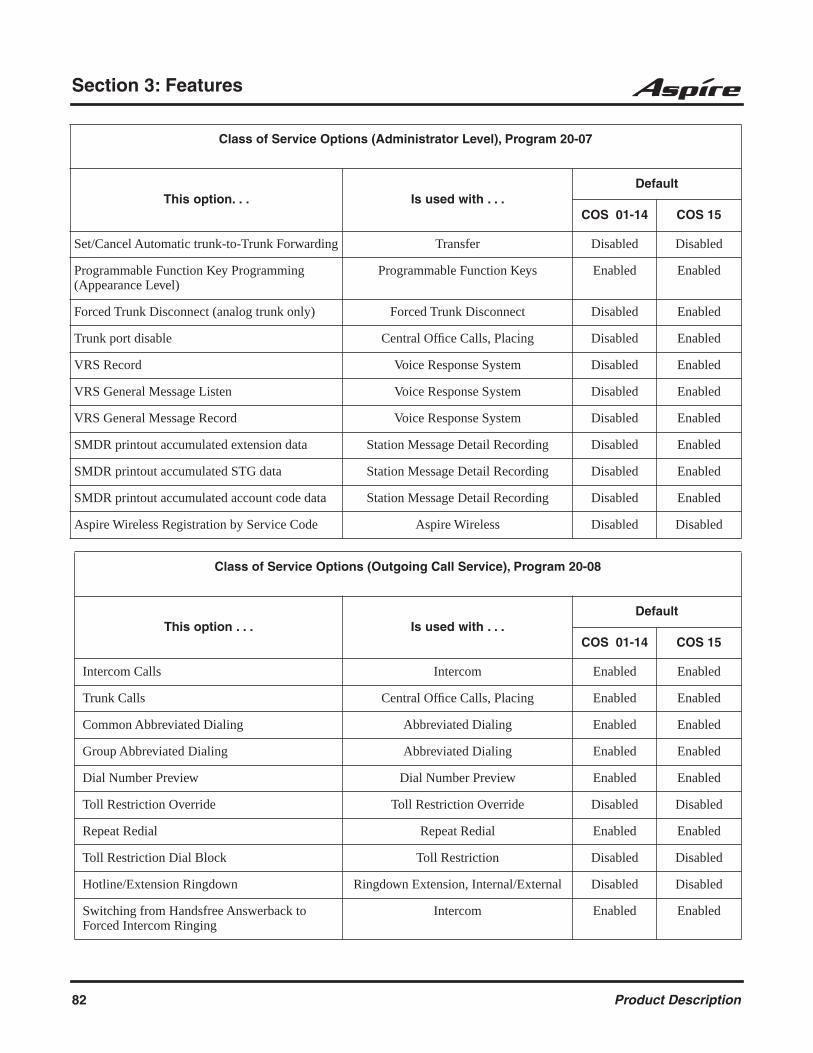
Section 3: Features
Set/Cancel Automatic trunk-to-Trunk Forwarding Transfer Disabled Disabled
Programmable Function Key Programming (Appearance Level)
Programmable Function Keys Enabled Enabled
Forced Trunk Disconnect (analog trunk only) Forced Trunk Disconnect Disabled Enabled
Trunk port disable Central Office Calls, Placing Disabled Enabled
VRS Record Voice Response System Disabled Enabled
VRS General Message Listen Voice Response System Disabled Enabled
VRS General Message Record Voice Response System Disabled Enabled
SMDR printout accumulated extension data Station Message Detail Recording Disabled Enabled
SMDR printout accumulated STG data Station Message Detail Recording Disabled Enabled
SMDR printout accumulated account code data Station Message Detail Recording Disabled Enabled
Aspire Wireless Registration by Service Code Aspire Wireless Disabled Disabled
Class of Service Options (Outgoing Call Service), Program 20-08
This option . . . Is used with . . . Default
COS 01-14 COS 15
Intercom Calls Intercom Enabled Enabled
Trunk Calls Central Office Calls, Placing Enabled Enabled
Common Abbreviated Dialing Abbreviated Dialing Enabled Enabled
Group Abbreviated Dialing Abbreviated Dialing Enabled Enabled
Dial Number Preview Dial Number Preview Enabled Enabled
Toll Restriction Override Toll Restriction Override Disabled Disabled
Repeat Redial Repeat Redial Enabled Enabled
Toll Restriction Dial Block Toll Restriction Disabled Disabled
Hotline/Extension Ringdown Ringdown Extension, Internal/External Disabled Disabled
Switching from Handsfree Answerback to Forced Intercom Ringing
Intercom Enabled Enabled
Class of Service Options (Administrator Level), Program 20-07
This option. . . Is used with . . . Default
COS 01-14 COS 15
82 Product Description

Section 3: Features
3
Protect for the call mode switching from caller(Internal Call)
Intercom Disabled Disabled
Department Group Step Calling Department Step Calling Enabled Enabled
CLIP Caller ID Disabled Disabled
Call Address Information Caller ID Disabled Disabled
Block Outgoing Caller ID Caller ID Disabled Disabled
Display E911 Dialed Extension Name and Number
E911 Compatibility Disabled Disabled
ARS Override map Automatic Route Selection Disabled Disabled
Class of Service Options (Outgoing Call Service), Program 20-09
This option . . . Is used with . . . Default
COS 01-14 COS 15
Second Call for DID/ DISA/ DIL/ E&M Central Office Calls Answering Disabled Disabled
Caller ID Display Caller ID Disabled Disabled
Sub Address Identification Caller ID Disabled Disabled
Notification for Incoming Call List existence Caller ID Disabled Disabled
Setting Handsfree Answerback or Forced Inter-com Ringing
Intercom Enabled Enabled
Incoming Time Information Display Time and Date Disabled Disabled
Class of Service Options (Answer Service), Program 20-10
This option . . . Is used with . . . Default
COS 01-14 COS 15
Group Call Pickup (Within Group) Group Call PickupCall Pickup Group
Enabled Enabled
Group Call Pickup (Another Group) Group Call PickupCall Pickup Group
Enabled Enabled
Class of Service Options (Outgoing Call Service), Program 20-08
This option . . . Is used with . . . Default
COS 01-14 COS 15
Product Description 83
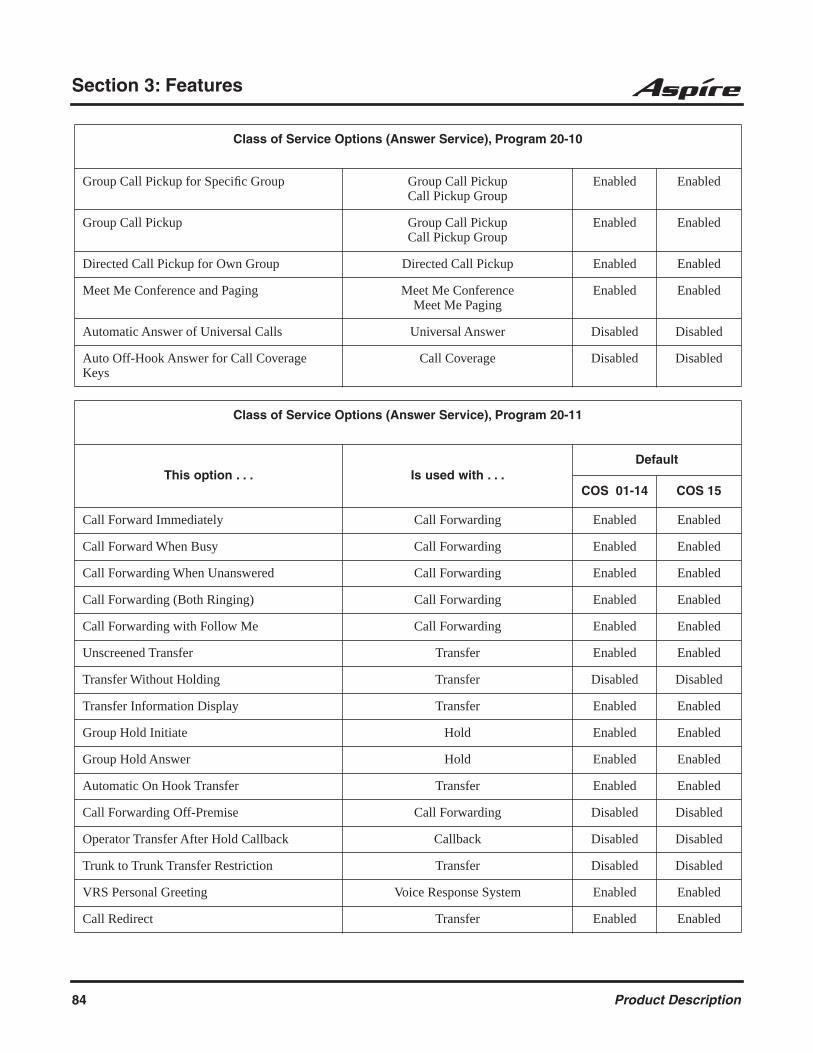
Section 3: Features
Group Call Pickup for Specific Group Group Call PickupCall Pickup Group
Enabled Enabled
Group Call Pickup Group Call PickupCall Pickup Group
Enabled Enabled
Directed Call Pickup for Own Group Directed Call Pickup Enabled Enabled
Meet Me Conference and Paging Meet Me ConferenceMeet Me Paging
Enabled Enabled
Automatic Answer of Universal Calls Universal Answer Disabled Disabled
Auto Off-Hook Answer for Call Coverage Keys
Call Coverage Disabled Disabled
Class of Service Options (Answer Service), Program 20-11
This option . . . Is used with . . . Default
COS 01-14 COS 15
Call Forward Immediately Call Forwarding Enabled Enabled
Call Forward When Busy Call Forwarding Enabled Enabled
Call Forwarding When Unanswered Call Forwarding Enabled Enabled
Call Forwarding (Both Ringing) Call Forwarding Enabled Enabled
Call Forwarding with Follow Me Call Forwarding Enabled Enabled
Unscreened Transfer Transfer Enabled Enabled
Transfer Without Holding Transfer Disabled Disabled
Transfer Information Display Transfer Enabled Enabled
Group Hold Initiate Hold Enabled Enabled
Group Hold Answer Hold Enabled Enabled
Automatic On Hook Transfer Transfer Enabled Enabled
Call Forwarding Off-Premise Call Forwarding Disabled Disabled
Operator Transfer After Hold Callback Callback Disabled Disabled
Trunk to Trunk Transfer Restriction Transfer Disabled Disabled
VRS Personal Greeting Voice Response System Enabled Enabled
Call Redirect Transfer Enabled Enabled
Class of Service Options (Answer Service), Program 20-10
84 Product Description

Section 3: Features
3
Set/Cancel Department Group Trunk-to-Trunk Forwarding
Tandem Trunking Enabled Enabled
Transfer Recall on Receiving COS Transfer Disabled Disabled
Normal/Extended Park Park Disabled Disabled
Transfer Recall on Originating COS Transfer Disabled Disabled
Restriction for Tandem Trunking on Hang Up Conference/Tandem Trunking Disabled Disabled
Class of Service Options (Supplementary Service), Program 20-13
This option . . . Is used with . . . Default
COS 01-14 COS 15
Long Conversation Alarm Warning Tone for Long Conversation Disabled Disabled
Long Conversation Cutoff (Incoming) Warning Tone for Long Conversation Disabled Disabled
Long Conversation Cutoff (Outgoing) Warning Tone for Long Conversation Disabled Disabled
Call Forwarding/DND Override Call Forwarding/DND Override Enabled Enabled
Intercom Off Hook Signaling Off Hook Signaling Enabled Enabled
Automatic Off Hook Signaling Off Hook Signaling Enabled Enabled
Message Waiting Message Waiting Enabled Enabled
Conference ConferenceMeet Me Conference
Enabled Enabled
Privacy Release Conference Enabled Enabled
Barge In Mode Barge In Disabled Disabled
Room Monitor, Initiating Extension Room Monitor Disabled Disabled
Room Monitor, Extension Being Monitored Room Monitor Disabled Disabled
Continued Dialing Continued Dialing Enabled Enabled
Department Calling Department Calling Enabled Enabled
Barge In, Initiate Barge In Disabled Disabled
Barge In, Receive Barge In Disabled Disabled
Class of Service Options (Answer Service), Program 20-11
This option . . . Is used with . . . Default
COS 01-14 COS 15
Product Description 85

Section 3: Features
Barge In Tone/Display Barge In Enabled Enabled
Programmable Function Key Programming (General Level)
Programmable Function Keys Enabled Enabled
Selectable Display Messaging Selectable Display Messaging Enabled Enabled
Account Code/Toll Restriction Operator Alert Account CodesToll Restriction
Disabled Disabled
Extension Name Name Storing Enabled Enabled
Busy Status Display Intercom Disabled Disabled
Display the Reason for Transfer Transfer Disabled Disabled
Privacy Release by Pressing Line Key Barge In Disabled Disabled
Transmission is cut when privacy release is used during trunk to trunk transfer.
Tandem Trunking Disabled Disabled
Group Listen Group Listen Enabled Enabled
Busy on seizing virtual extension Multiple Directory Numbers/ Call Coverage
Enabled Enabled
Allow COS to be Changed Class of Service Disabled Disabled
Paging Display Paging, ExternalPaging, Internal
Enabled Enabled
Background Music Background Music Enabled Enabled
Connected Line identification (COLP) Caller ID Disabled Disabled
Deny Multiple Barge Ins Barge In Disabled Disabled
ACD Supervisor’s Position Enhancement Automatic Call Distribution Disabled Disabled
Block Manual Off Hook Signaling Off Hook Signaling Disabled Disabled
Block Camp On Call Waiting / Camp On Disabled Disabled
Call Duration Timer Call Timer Disabled Disabled
Headset Ringing Headset Operation Disabled Disabled
ACD Queue Display Automatic Call Distribution Disabled Disabled
Do Not Disturb Do Not Disturb Enabled Enabled
Class of Service Options (Supplementary Service), Program 20-13
This option . . . Is used with . . . Default
COS 01-14 COS 15
86 Product Description
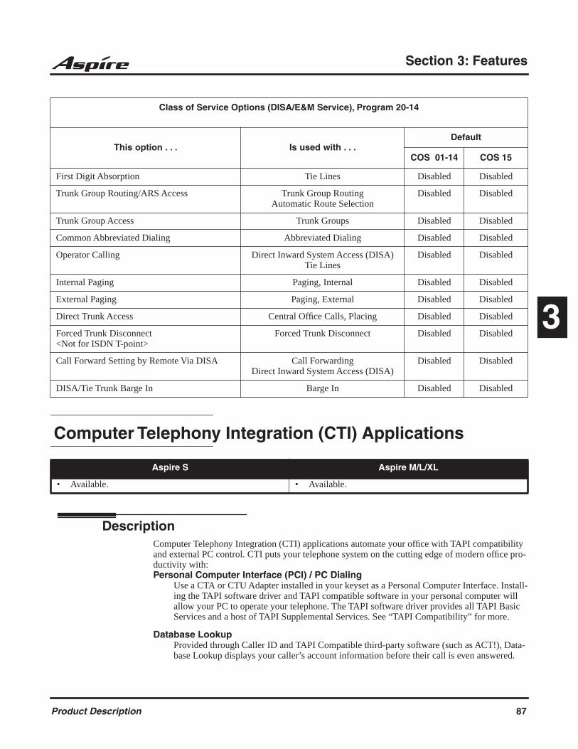
Section 3: Features
3
Computer Telephony Integration (CTI) Applications
DescriptionComputer Telephony Integration (CTI) applications automate your office with TAPI compatibility and external PC control. CTI puts your telephone system on the cutting edge of modern office pro-ductivity with: Personal Computer Interface (PCI) / PC Dialing
Use a CTA or CTU Adapter installed in your keyset as a Personal Computer Interface. Install-ing the TAPI software driver and TAPI compatible software in your personal computer will allow your PC to operate your telephone. The TAPI software driver provides all TAPI Basic Services and a host of TAPI Supplemental Services. See “TAPI Compatibility” for more.
Database Lookup Provided through Caller ID and TAPI Compatible third-party software (such as ACT!), Data-base Lookup displays your caller’s account information before their call is even answered.
Class of Service Options (DISA/E&M Service), Program 20-14
This option . . . Is used with . . . Default
COS 01-14 COS 15
First Digit Absorption Tie Lines Disabled Disabled
Trunk Group Routing/ARS Access Trunk Group RoutingAutomatic Route Selection
Disabled Disabled
Trunk Group Access Trunk Groups Disabled Disabled
Common Abbreviated Dialing Abbreviated Dialing Disabled Disabled
Operator Calling Direct Inward System Access (DISA)Tie Lines
Disabled Disabled
Internal Paging Paging, Internal Disabled Disabled
External Paging Paging, External Disabled Disabled
Direct Trunk Access Central Office Calls, Placing Disabled Disabled
Forced Trunk Disconnect <Not for ISDN T-point>
Forced Trunk Disconnect Disabled Disabled
Call Forward Setting by Remote Via DISA Call ForwardingDirect Inward System Access (DISA)
Disabled Disabled
DISA/Tie Trunk Barge In Barge In Disabled Disabled
Aspire S Aspire M/L/XL
• Available. • Available.
Product Description 87
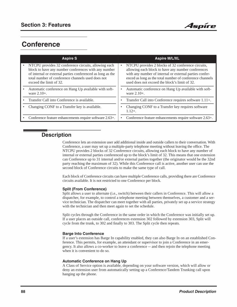
Section 3: Features
Conference
DescriptionConference lets an extension user add additional inside and outside callers to their conversation. With Conference, a user may set up a multiple-party telephone meeting without leaving the office. The NTCPU provides 2 blocks of 32 Conference circuits, allowing each block to have any number of internal or external parties conferenced up to the block’s limit of 32. This means that one extension can Conference up to 31 internal and/or external parties together (the originator would be the 32nd party reaching the maximum of 32). While this Conference call is active, another user can use the second block of Conference circuits to make the same type of call.
Each block of Conference circuits can have multiple Conference calls, providing there are Conference circuits available. It is not restricted to one Conference per block.
Split (From Conference) Split allows a user to alternate (i.e., switch) between their callers in Conference. This will allow a dispatcher, for example, to control a telephone meeting between themselves, a customer and a ser-vice technician. The dispatcher can meet together with all parties, privately set up a service strategy with the technician and then meet again to set the schedule.
Split cycles through the Conference in the same order in which the Conference was initially set up. If a user places an outside call, conferences extension 302 followed by extension 303, Split will cycle from the trunk, to 302 and finally to 303. The Split cycle then repeats.
Barge Into ConferenceIf a user’s extension has Barge In capability enabled, they can also Barge In on an established Con-ference. This permits, for example, an attendant or supervisor to join a Conference in an emer-gency. It also allows a co-worker to leave a conference -- and then rejoin the telephone meeting when it is convenient to do so.
Automatic Conference on Hang UpA Class of Service option is available, depending on your software version, which will allow or deny an extension user from automatically setting up a Conference/Tandem Trunking call upon hanging up the phone.
Aspire S Aspire M/L/XL
• NTCPU provides 32 conference circuits, allowing each block to have any number conferences with any number of internal or external parties conferenced as long as the total number of conference channels used does not exceed the limit of 32.
• Automatic conference on Hang Up available with soft-ware 2.10+.
• Transfer Call into Conference is available.
• Changing CONF to a Transfer key is available.
• Conference feature enhancements require software 2.63+.
• NTCPU provides 2 blocks of 32 conference circuits, allowing each block to have any number conferences with any number of internal or external parties confer-enced as long as the total number of conference channels used does not exceed the block’s limit of 32.
• Automatic conference on Hang Up available with soft-ware 2.10+.
• Transfer Call into Conference requires software 1.11+.
• Changing CONF to a Transfer key requires software 1.12+.
• Conference feature enhancements require software 2.63+.
88 Product Description

Section 3: Features
3
Transfer Call Into ConferenceAn extension with Barge In capability can Transfer a call into an existing Conference. This would allow, for example, an attendant to locate co-workers and then Transfer them into an existing tele-phone meeting. There is no need for the attendant to locate all the parties at the same time and sequentially add them into the Conference.
Change CONF to a Transfer KeyAn option is available which allows an extension’s CONF key to be programmed for Conference or for Transfer. When set for Transfer, the user places a call on hold, dials the extension to which it should be transferred, the presses the CONF key. The call is then transferred. When set for Confer-ence, with an active call, the user presses the CONF key, places a second call, then presses the CONF key twice. All the calls are then connected.
Conference Feature EnhancedThe Conference feature has been enhanced with the ability to:
Allow a user in an active Conference call to add another party.Older software would not allow a call to be added to an existing Conference unless the
call was put on hold or park and the Conference reestablished, then adding all parties into the Conference at once.
Break up a Conference call by pressing Hold.With older software, using line keys, if you set up a 3-party (1 internal user and 2
trunks) Conference, if you placed the Conference on hold and pressed one of the line keys, the conference would restart. You could not undo a Conference once it was set by simply placing Hold.
Drop a trunk or trunks from the Conference.While in a Conference, with older software, you could not drop one of the parties.
Conference, Voice Call/Privacy Release
DescriptionVoice Call Conference lets extension user’s in the same work area join in a trunk Conference. To initiate a Voice Call Conference, an extension user just presses the Voice Call Conference key and tells their co-workers to join the call. The system releases the privacy on the trunk, and other users can just press the trunk’s line key to join the call.
Voice Call Conference does not use the telephone system features to announce the call. The person initiating the Voice Call Conference just announces it “through the air.”
Aspire S Aspire M/L/XL
• NTCPU provides 32 conference circuits, allowing each block to have any number conferences with any number of internal or external parties conferenced as long as the total number of conference channels used does not exceed the limit of 32.
• NTCPU provides 2 blocks of 32 conference circuits, allowing each block to have any number conferences with any number of internal or external parties confer-enced as long as the total number of conference channels used does not exceed the block’s limit of 32.
Product Description 89

Section 3: Features
Privacy Mode Toggle OptionThe Privacy Mode Toggle option allows an extension user to quickly change an outside call from the non-private mode to the private mode. This would help a workgroup supervisor, for example, that needed to quickly monitor any group member’s call. If the supervisor wanted to make a “secure” call, however, they could quickly switch the line’s mode and be assured that their call would not be monitored. If the outside call is on a line key, the user just presses the line key to switch modes. If the call is on a loop key, the user presses their Privacy Release function key instead.
For systems using the Privacy Mode Toggle option, trunks initially have the privacy released. If pri-vacy is desired for a trunk, use the toggle option or press the Privacy Release function key to switch modes.
Continued Dialing
DescriptionContinued Dialing allows an extension user to dial a call, wait for the called party to answer and then dial additional digits. This helps users that need services like Voice Mail, automatic banking and Other Common Carriers (OCCs).
There are two types of Continued Dialing:
Continued Dialing for Intercom CallsDepending on an extension’s Class of Service, a keyset user may be able to dial additional digits after their Intercom call connects. In systems with Voice Mail, for example, Continued Dialing lets extension users dial the different options after the Voice Mail answers. Without Continued Dialing, extension users cannot access these Voice Mail options.
Continued Dialing for Trunk CallsContinued Dialing gives a user access to outside services like automatic banking, an outside Automated Attendant, bulletin boards and Other Common Carriers (OCCs). After the outside service answers, the user can dial digits for whatever options the services allow. Without Con-tinued Dialing, the system’s Toll Restriction will cut off the call after a specific number of dialed digits. See Programming below for additional information.
Aspire S Aspire M/L/XL
• Available. • Available.
NOTICE
Continued Dialing may make the system more susceptible to toll fraud.
90 Product Description
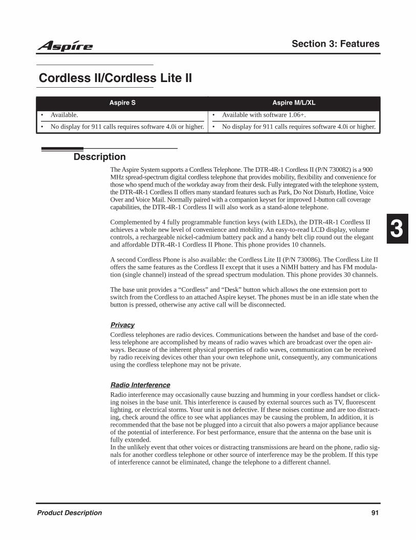
Section 3: Features
3
Cordless II/Cordless Lite II
DescriptionThe Aspire System supports a Cordless Telephone. The DTR-4R-1 Cordless II (P/N 730082) is a 900 MHz spread-spectrum digital cordless telephone that provides mobility, flexibility and convenience for those who spend much of the workday away from their desk. Fully integrated with the telephone system, the DTR-4R-1 Cordless II offers many standard features such as Park, Do Not Disturb, Hotline, Voice Over and Voice Mail. Normally paired with a companion keyset for improved 1-button call coverage capabilities, the DTR-4R-1 Cordless II will also work as a stand-alone telephone.
Complemented by 4 fully programmable function keys (with LEDs), the DTR-4R-1 Cordless II achieves a whole new level of convenience and mobility. An easy-to-read LCD display, volume controls, a rechargeable nickel-cadmium battery pack and a handy belt clip round out the elegant and affordable DTR-4R-1 Cordless II Phone. This phone provides 10 channels.
A second Cordless Phone is also available: the Cordless Lite II (P/N 730086). The Cordless Lite II offers the same features as the Cordless II except that it uses a NiMH battery and has FM modula-tion (single channel) instead of the spread spectrum modulation. This phone provides 30 channels.
The base unit provides a “Cordless” and “Desk” button which allows the one extension port to switch from the Cordless to an attached Aspire keyset. The phones must be in an idle state when the button is pressed, otherwise any active call will be disconnected.
PrivacyCordless telephones are radio devices. Communications between the handset and base of the cord-less telephone are accomplished by means of radio waves which are broadcast over the open air-ways. Because of the inherent physical properties of radio waves, communication can be received by radio receiving devices other than your own telephone unit, consequently, any communications using the cordless telephone may not be private.
Radio InterferenceRadio interference may occasionally cause buzzing and humming in your cordless handset or click-ing noises in the base unit. This interference is caused by external sources such as TV, fluorescent lighting, or electrical storms. Your unit is not defective. If these noises continue and are too distract-ing, check around the office to see what appliances may be causing the problem, In addition, it is recommended that the base not be plugged into a circuit that also powers a major appliance because of the potential of interference. For best performance, ensure that the antenna on the base unit is fully extended.In the unlikely event that other voices or distracting transmissions are heard on the phone, radio sig-nals for another cordless telephone or other source of interference may be the problem. If this type of interference cannot be eliminated, change the telephone to a different channel.
Aspire S Aspire M/L/XL
• Available.
• No display for 911 calls requires software 4.0i or higher.
• Available with software 1.06+.
• No display for 911 calls requires software 4.0i or higher.
Product Description 91

Section 3: Features
If should also be noted that some cordless telephones operate at frequencies that may cause inter-ference to nearby TVs and VCRs. To minimize or prevent such interference, the base unit should not be placed near or on top of a TV or VCR. If interference is experienced, moving the cordless telephone farther away from the TV or VCR will often reduce or eliminate the interference.
Multiple Cordless TelephonesIf you want to use more than one cordless telephone in the same office, they must operate on differ-ent channels. Press the channel key to select a channel that provides the clearest communication.
In ideal conditions, multiple spread spectrum type cordless phones (Cordless II ) can be utilized in the same environment. However, due to the possible interference problems caused by the bases being placed in close proximity to each other, the following is recommended:
Spread Spectrum Phones (Cordless II P/N 730088)Where users require greater range on the cordless phones and 3 or less cordless phones are being used at a specific site, we recommend using the spread spectrum cordless phone.
FM Modulation Phones (Cordless Lite II P/N 730087)Where more than 3 cordless phones are to be used at one specific site, we recommend using the FMmodulation cordless phones which have 30-channel capability.
* Note:
1. The range of the phones depends largely on the environmental factors, such as the building structure, the size of the room, RF interference and other electronic equipment installed in the same area. For optimum range and performance, the following is suggested:
2. Place the base units at least 15 feet apart. The performance of the phones become more stable when the distance between the bases is greater.
3. Place the base unit in the center of the coverage area. If the phone will also be used in an out-door area, like a parking lot, install the base unit in an area close to the window.
4. If a phone experiences interference and noise, press the channel key to select another channel.
Clearing 911 CallsDepending on your software, Cordless II and Cordless Lite II phones will not display the E911 message. With older software, if the system was set up to display the E911 Alarm (Program 20-08-16), there was no way for a Cordless II or Cordless Lite II user to clear the display.
Department Calling
DescriptionWith Department Calling, an extension user can call an idle extension within a preprogrammed Department Group by dialing the group’s pilot number. The call would ring the first available extension in the group. For example, this would let a caller dial the Sales department just by know-ing the Sales department’s pilot number. The caller would not have to know any of the Sales depart-ment’s extension numbers.
Aspire S Aspire M/L/XL
• Available - 8 Department Groups. • Available - 64 Department Groups.
92 Product Description

Section 3: Features
3
There are two types of routing available with Department Calling: Priority Routing and Circular Routing. With Priority Routing, an incoming call routes to the highest priority extensions first. Lower priority extensions ring only if all higher priority extensions are busy. With Circular Rout-ing, each call rings a new extension (with circular routing, a new call will ring the extension which has been idle the longest in the group). The ringing order is based on an extension’s priority. In a Department Group with extensions 310 (Priority 1), 311 (Priority 2) and 312 (Priority 3) The first call rings 310. The second call rings 311. The third call rings 312. The fourth call rings 310 and the cycle repeats.
Note: When programming, the high priority extensions have low priority numbers. For example, priority 1 has a higher priority than priority 10.
Overflow RoutingDepartment Calling also provides overflow routing for extensions within the group. If a user directly dials a busy extension within a Department Group, the system can optionally route the call to the first available group member. The system follows Program 22-15-03 and 22-15-05 timers for playing the periodic VRS message.
User Log Out/Log InAn extension user can log out and log in to a Department Calling Group. By logging out, the user removes their extension from the group. Once logged out, Department Calling bypasses their exten-sion. When they log back in, Department Calling routes to their extension normally. All users can dial a code to log in or log out of their Department Calling Group. A keyset can optionally have a function key programmed for one-button log in and log out operation.
Enhanced HuntingDepartment Calling is enhanced with expanded hunting capabilities. Hunting sets the conditions under which calls to a Department Group pilot number will cycle through the members of the group. The hunting choices are:
BusyA call to the pilot number will hunt past a busy group member to the first available extension.
Not answeredA call to the pilot number will cycle through the idle members of a Department Calling group. The call will continue to cycle until it is answered or the calling party hangs up. If the Depart-ment Group has Priority Routing enabled, and the highest priority member is busy, the call will not route.
Busy or not answeredA call to the pilot number will cycle through the idle members of a Department Calling group. The call will continue to cycle until it is answered or the calling party hangs up. Calls into groups with Priority Routing and Circular Routing route identically.
Simultaneous ringingAll idle members of the Department Group ring simultaneously. Calls do not cycle between group members.
If all members of the Department Group are busy, an incoming or transferred call to the group’s pilot number will queue for an available member. Each group has a queue that can hold any number of waiting calls. If a display phone is waiting in queue, the user will see: WAITING (group name). If a transferred call in queue is an outside call, and the system has DSP daughter board installed with the VRS, the queued caller will hear, “Please hold on. All lines are busy. Your call will be answered when a line becomes free.”
The VRS can also transfer calls to Department Groups. Refer to “Voice Response System (VRS)” feature for more information on setting up the VRS.
Product Description 93

Section 3: Features
The system prevents hunting to a Department Group extension if it is:
Busy on a call
In Do Not Disturb
Call Forwarded
Department Step Calling
DescriptionAfter calling a busy Department Calling Group member, an extension user can have Department Step Calling quickly call another member in the group. The caller does not have to hang up and place another Intercom call if the first extension called is unavailable. Department Step Calling also allows an extension user to cycle through the members of a Department Group.
Dial Number Preview
DescriptionDialing Number Preview lets a display keyset user dial and review a number before the system dials it out. Dialing Number Preview helps the user avoid dialing errors.
Dial Pad Confirmation Tone
DescriptionFor an extension with Dial Pad Confirmation Tone enabled, the user hears a beep each time they press a key. This is helpful for Intercom calls and Dial Pulse trunk calls, since these calls provide no Call Progress tones.
Aspire S Aspire M/L/XL
• Available. • Available.
Aspire S Aspire M/L/XL
• Available. • Available.
Aspire S Aspire M/L/XL
• Available. • Available.
94 Product Description
Section 3: Features
3
Dial Tone Detection
DescriptionIf a trunk has Dial Tone Detection enabled, the system monitors for dial tone from the telco or PBX when a user places a call on that trunk. If the user accesses the trunk directly (by pressing a line key or dialing #9 and the trunk’s number), the system will drop the trunk if dial tone does not occur. If the user access the trunk via a Trunk Group (by dialing a trunk group code or automatically through a feature like Last Number Redial), the system can drop the trunk or optionally skip to the next trunk in the group. Refer to the chart under Programming below for more.
Dial Tone Detection is available for the following features:
Automatic Route Selection Abbreviated Dialing Central Office Calls, Placing Last Number Redial Loop Keys (outbound) Save Number Dialed T1 Trunking (with ANI/DNIS Compatibility) Tie Lines Trunk Group Routing Trunk Groups
Direct Inward Dialing (DID)
DescriptionDirect Inward Dialing (DID) lets outside callers directly dial system extensions. DID saves time for callers who know the extension number they wish to reach. To place a DID call, the outside caller dials the local exchange (NNX) and additional digits to ring the telephone system extension. For example, DID number 926-5400 can directly dial extension 400. The caller does not have to rely on attendant or secretary call screening to complete the call.
Aspire S Aspire M/L/XL
• Available
• Tone Detection Setup is available.
• The Next Trunk in Rotary if No Dial Tone option is available.
• Available.
• Tone Detection Setup is available.
• The Next Trunk in Rotary if No Dial Tone option is available.
Aspire S Aspire M/L/XL
• Available - 20 DID Translation Tables can be divided between 2000 entries.
• DID routing can follow ring group programming on transfers for busy/no answer calls.
• Available - 20 DID Translation Tables can be divided between 2000 entries.
• DID routing can follow ring group programming on transfers for busy/no answer calls with software 1.11+.
Product Description 95
Section 3: Features
Note: Direct Inward Dialing requires DID service from telco.
In addition to direct dialing of system extensions, DID provides:
DID Dialed Number Translation Flexible DID Service Compatibility DID Intercept DID Camp-On
DID Dialed Number Translation DID allows different tables for DID number translation. This gives you more flexibility when buying DID service from telco. If you can’t buy the exact block of numbers you need (e.g., 301-556), use the translation tables to convert the digits received. For example, a translation table could convert digits 501-756 to extension numbers 301-556.
The Aspire system has 2000 DID Translation Table entries that you can allocate among the 20 DID Translation Tables. There is one translation made in each entry. For a simple installation, you can put all 2000 entries in the same table. For more flexibility, you can optionally distribute the 2000 entries among the 20 tables.
In addition to number conversion, each DID Translation Table entry can have a name assigned to it. When the DID call rings the destination extension, the programmed name displays.
Flexible DID Service CompatibilityYou can program the system to be compatible with three and four digit DID service. With four digit service, the telco sends four digits to the system for translation. With three digit service, the telco sends three digits to the system for translation. Be sure to program your system for compati-bility with the provided telco service. For example, if the telco sends four digits, make sure you set up the translation tables to accept the four digits.
The system is compatible with Dial Pulse (DP) and DTMF DID signaling. DID trunks can be either wink start or immediate start.
DID Camp-OnDID Camp-On sets what happens to DID calls to busy extensions when you have Busy Intercept disabled. With DID Camp-On enabled, a call to a busy extension camps-on for the DID Ring No Answer Time interval. It then diverts to the programmed DID Intercept extension ring group or Voice Mail. Without DID Camp-On, the caller to the busy extension just hears busy tone.
DID Routing Through the VRSDID calls can optionally route through the VRS. The DID caller hears an initial Automated Atten-dant Greeting explaining their dialing options. If the caller mis-dials, they can hear a second greet-ing with additional instructions. For example, the first Automated Attendant Greeting can be, “Thank you for calling. Please dial the extension number you wish to reach or dial 0 for the opera-tor.” If the caller inadvertently dials an extension that doesn’t exist, they could hear, “The extension you dialed is unavailable. Please dial 0 for assistance or dial # to leave a message so we can call you back.”
You assign Automated Attendant greetings (i.e., VRS Messages) to the numbers in each Translation Table. This provides you with extensive flexibility when determining which greetings the system should play for which dialed numbers. You could, for example, set up 926 5401 through 926 5449 to route to extensions 301- 349, and have 926 5450 route to the automated attendant.
96 Product Description

Section 3: Features
3
The system allows an extension to be defined as a 1-digit number which can be dialed by the out-side caller on a DID/DISA trunk using the VRS. The outside caller is able to access to desired extension/department group by dialing only 1 digit after the system answers the call. If the same number is used as the first digit of an extension number as well as the 1-digit access code for DID/DISA, the outside caller will not be able to access the extension.
Example: If ‘2’ is defined as a 1-digit access code to department group 300, outside callers cannot access extensions 200-299 directly.
SMDR Includes Dialed NumberThe SMDR report can optionally print the trunk’s name (entered in system programming) or the number the incoming caller dialed (i.e., the dialed DID digits). This gives you the option of analyz-ing the SMDR report based on the number your callers dial. (This option also applies to an ISDN trunk as well.)
DID InterceptDID Intercept automatically reroutes DID calls under certain conditions. There are three types of DID Intercept:
Vacant Number InterceptIf a caller dials an extension that does not exist or mis-dials, Vacant Number Intercept can reroute the call to the programmed DID Intercept extension ring group or Voice Mail. Without Vacant Number Intercept, the caller hears error tone after mis-dialing.
Busy InterceptBusy Intercept determines DID routing when a DID caller dials a busy extension. If Busy Intercept is enabled, the call immediately routes to the programmed DID Intercept extension ring group or Voice Mail. If Busy Intercept is disabled, the call follows DID Camp-On pro-gramming (see below).
Ring-No-Answer InterceptRing-No-Answer Intercept sets the routing options for DID calls that ring unanswered at the destination extension. With Ring-No-Answer Intercept enabled, the unanswered call reroutes to the DID Intercept extension ring group or Voice Mail after the DID Ring-No-Answer Time interval. If Ring-No-Answer Intercept is disabled, the unanswered call rings the destination until the outside caller hangs up.
Delayed DIDDelayed DID allows a user a pre-programmed amount of time to answer a call. If the call is not answered within this time period, the system automatically answers the call. An outside party will hear a voice message, music, or dial tone according to the following conditions:
If a VRS is installed, the system sends a pre-recorded message from the VRS.
If a customer-provided audio system (example: tape recorder) is connected, an error message or music can be played for the caller.
If there is no equipment connected for an announcement, the system sends a unique dial tone to the outside caller.
This feature is not available for the normal incoming call on ISDN trunks.
DID Intercept Destination for Each DID NumberWith this feature the system allows you to program a DID Intercept destination for a DID number which receives no answer or busy call. The system can be programmed to use a trunk ring group, the VRS or the voice mail as the programmed destination. Each vacant number intercept for a DID number can have two destinations. The first destination is for an invalid DID number, busy or no answer extension. The second destination is for a no answer trunk ring group.
Product Description 97
Section 3: Features
For busy or no answer intercept calls, a third destination can be defined in Program 22-12. If the first and third destinations are programmed but the second destination is not, the incoming call goes to the third destination after the first destination. If the first and second destinations are not pro-grammed, but the third destination is, the call goes directly to the third destination.
This feature works for DID trunks with a trunk service type 1 in Program 22-02. Other types of trunks may use the DID table, but the DID intercept feature is not yet supported.
With the DID Intercept for each DID number feature, when the primary destination (Program 22-11-05) is set to Voice Mail, the Voice Mail protocol is:
1. Busy Intercept = Forward Busy2. Ring-No-Answer Intercept = Forward RNA
When the secondary destination (Program 22-11-06) is set to Voice Mail, the Voice Mail protocol is based on the first destination's routing. When the incoming call is forwarded to the first destination by a busy intercept, the Voice Mail protocol will be that it forwards busy calls. When the incoming call is routed to the first destination by a ring-no-answer intercept, the protocol will be that it for-wards ring-no-answer. The Voice Mail will transfer the calls to the mailbox number defined in Pro-gram 22-11-02.
Note: Any valid DID number must be entered in the DID table (Program 22-11). If a valid DID number is not entered, there will be no ring destination for any incoming calls to that num-ber (the calls will not ring any extension in the system).
Calls Can Follow Ring Group Programming for Transferring CallsAn option has been added to Program 22-11 which allows you to determine if the DID routing should use the programmed ring group entry in Program 22-12-01 when transferring calls from a busy or no answer number.
Federal Communications Commission DID RequirementsAllowing this equipment to operate in a manner that does not provide proper answer supervision signaling is in violation of Part 68 rules.
This equipment returns answer supervision to the Public Switched Telephone Network when the DID trunk is:
Answered by the called station Answered by the attendant Routed to a recorded announcement that can be administered by the CPE user Routed to a dial prompt
This equipment returns answer supervision on all DID calls forwarded back to the Public Switched Telephone Network. Permissible exceptions are when:
A call is unanswered A busy tone is received A reorder tone is received
98 Product Description
Section 3: Features
3
Direct Inward Line (DIL)
DescriptionA Direct Inward Line (DIL) is a trunk that rings an extension, virtual extension or Department Group directly. Since DILs only ring one extension or group (i.e., the DIL destination), employees always know which calls are for them. For example, a company operator can have a Direct Inward Line for International Sales Information. When outside callers dial the DIL’s phone number, the call rings the operator on the International Sales line key. The DIL does not ring other extensions.
DIL Delayed RingingExtensions in a Ring Group can have delayed ringing for another extension’s DIL. If the DIL is not answered at its original destination, it rings the DIL No Answer Ring Group. This could help a Technical Service department, for example, that covers calls for an Inside Sales department. If the Inside Sales calls are not answered, they ring into the Technical Service department.
Direct Inward System Access (DISA)
DescriptionDISA permits outside callers to directly dial system extensions, trunks and selected features. This could help an employee away from the office that wants to directly dial co-workers or use the com-pany’s trunks for long distance calls. To use DISA, the employee:
Dials the telephone number that rings the DISA trunk
Waits for the DISA trunk to automatically answer with a unique dial tone
Dials the 6-digit DISA password (access code)
Waits for a second unique dial tone
Accesses a system trunk, uses a selected feature or dials a system extension
DISA calls ring system extensions like other outside calls. If an extension has a line key for the DISA trunk, the call rings that key. If the extension does not have a line key, the call rings an idle CALL key.
Aspire S Aspire M/L/XL
• Available - 8 trunks and 8 Department Groups.With software prior to 2.50 - 26 extensions and 24 vir-tual extensions. With 2.50+, 50 extensions and 24 virtual extensions.
• Available.Aspire M/L: 200 trunks, 64 Department Groups, 256 extensions, and 256 virtual extensions.Aspire XL: 200 trunks, 64 Department Groups, 384 extensions, and 256 virtual extensions.
Aspire S Aspire M/L/XL
• Available - 15 users, 15 DISA Classes of Service and 8 trunks.
• Available - 15 users, 15 DISA Classes of Service and 200 trunks.
Product Description 99

Section 3: Features
You can set DISA operation differently for each Night Service mode. For example, a trunk can be a normal trunk during the day and a DISA trunk at night. You can also set the routing for DISA trunks when the caller dials a busy or unanswered extension, dials incorrectly or forgets to dial.
DISA Class of ServiceDISA Class of Service provides features and dialing restrictions for DISA callers. This allows you to control the capabilities of the DISA callers dialing into your system. When a DISA caller first accesses the system, they must enter a DISA password before proceeding. The system associates the password entered with a specific user number, which in turn has a Class of Service. If the Class of Service allows the action (such as making outgoing trunk calls), the call goes through. If the DISA Class of Service doesn’t allow the action, the system prevents the call. The DISA Class of Service options are:
Trunk Group Routing/ARS AccessWhen a DISA caller dials into the system, they may be able to dial 9 and place outside calls. Any toll charges are incurred by the system. The call follows the system’s Trunk Group Access or Automatic Route Selection - whichever is enabled.
Trunk Group AccessDISA callers may be able to access a specific trunk group for outgoing calls through the sys-tem. To access a Trunk Group, the user dials Service Code 804 followed by the Trunk Group number (e.g., 1). This allows the DISA caller to place an outgoing call over the selected group. Trunk Group Access bypasses the system’s Trunk Group Routing/ARS/Trunk Access Maps. As with dial 9 access, any toll charges are incurred by the system. Also see Direct Trunk Access below.
Common Abbreviated DialingThe system’s Common Abbreviated Dialing bins may be available to DISA callers. This could save the DISA caller time when dialing.
Operator CallingA DISA caller may be able to dial 0 for the system’s operator.
PagingInternal and External Paging may be available to DISA callers. This allows co-workers in adjacent facilities, for example, to broadcast announcements to each other.
Direct Trunk AccessDISA callers may be able to select a specific trunk for outgoing calls through the system. To directly access a trunk, the user dials Service Code #9 followed by the trunk’s number (e.g., 001). This allows the DISA caller to place an outgoing call over the selected trunk. Direct Trunk Access bypasses the system’s Trunk Group Routing/ARS/Trunk Access Maps. As with dial 9 access, any toll charges are incurred by the system. Also see Trunk Group Access above.
Call ForwardDISA callers may be able to set Call Forwarding to redirect an extension’s calls to another extension. Call Forwarding ensures that the user’s calls are covered when they are away from their work area.
DISA/Tie Trunk Barge InThe DISA/Tie Trunk Barge In option allows a tie line caller to break into another extension’s established call. This sets up a three-way conversation between the intruding party and the two parties on the initial call.
DISA Toll Restriction The digits a DISA caller dials for an outgoing call may be subject to the system’s Toll Restriction. For example, Toll Restriction can prevent users from dialing a 1-900 service. When an incoming DISA caller tries to use system trunks to dial 1-900, Toll Restriction will deny the call.
100 Product Description
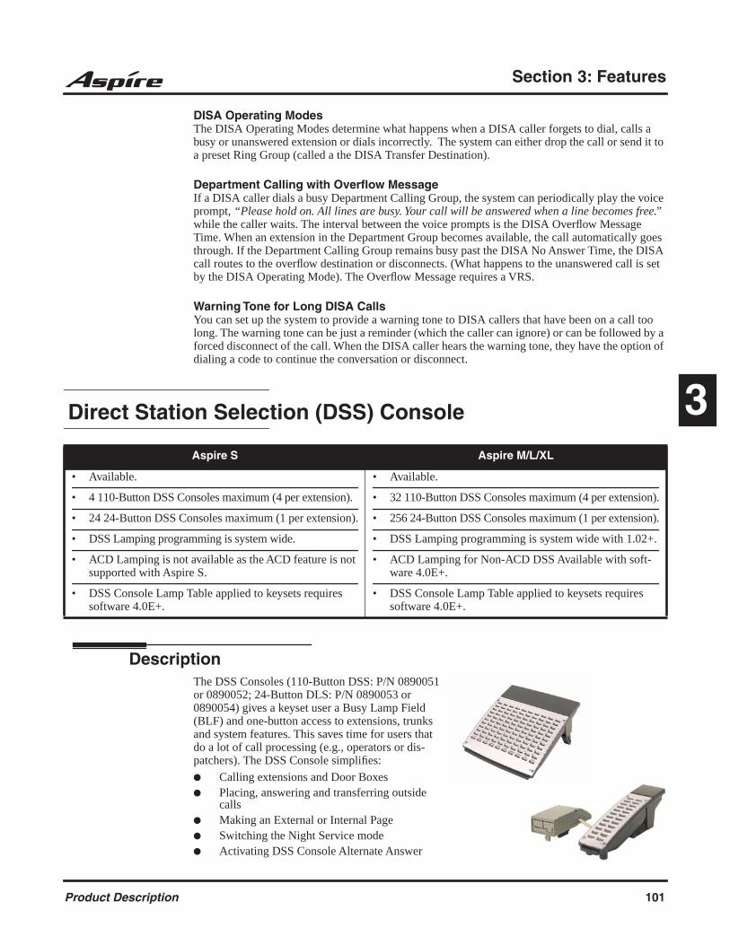
Section 3: Features
3
DISA Operating Modes The DISA Operating Modes determine what happens when a DISA caller forgets to dial, calls a busy or unanswered extension or dials incorrectly. The system can either drop the call or send it to a preset Ring Group (called a the DISA Transfer Destination).
Department Calling with Overflow MessageIf a DISA caller dials a busy Department Calling Group, the system can periodically play the voice prompt, “Please hold on. All lines are busy. Your call will be answered when a line becomes free.” while the caller waits. The interval between the voice prompts is the DISA Overflow Message Time. When an extension in the Department Group becomes available, the call automatically goes through. If the Department Calling Group remains busy past the DISA No Answer Time, the DISA call routes to the overflow destination or disconnects. (What happens to the unanswered call is set by the DISA Operating Mode). The Overflow Message requires a VRS.
Warning Tone for Long DISA CallsYou can set up the system to provide a warning tone to DISA callers that have been on a call too long. The warning tone can be just a reminder (which the caller can ignore) or can be followed by a forced disconnect of the call. When the DISA caller hears the warning tone, they have the option of dialing a code to continue the conversation or disconnect.
Direct Station Selection (DSS) Console
DescriptionThe DSS Consoles (110-Button DSS: P/N 0890051 or 0890052; 24-Button DLS: P/N 0890053 or 0890054) gives a keyset user a Busy Lamp Field (BLF) and one-button access to extensions, trunks and system features. This saves time for users that do a lot of call processing (e.g., operators or dis-patchers). The DSS Console simplifies:
Calling extensions and Door Boxes Placing, answering and transferring outside
calls Making an External or Internal Page Switching the Night Service mode Activating DSS Console Alternate Answer
Aspire S Aspire M/L/XL
• Available.
• 4 110-Button DSS Consoles maximum (4 per extension).
• 24 24-Button DSS Consoles maximum (1 per extension).
• DSS Lamping programming is system wide.
• ACD Lamping is not available as the ACD feature is not supported with Aspire S.
• DSS Console Lamp Table applied to keysets requires software 4.0E+.
• Available.
• 32 110-Button DSS Consoles maximum (4 per extension).
• 256 24-Button DSS Consoles maximum (1 per extension).
• DSS Lamping programming is system wide with 1.02+.
• ACD Lamping for Non-ACD DSS Available with soft-ware 4.0E+.
• DSS Console Lamp Table applied to keysets requires software 4.0E+.
Product Description 101

Section 3: Features
The DSS Console also provides DSS Console Alternate Answer. This lets a keyset user with a DSS Console quickly reroute their calls to a co-worker. When the user places their console off-duty (by pressing the ALT. key), their calls route automatically to the programmed co-worker. Transferred and dial “0” calls ring both DSS Consoles and, if the VRS is installed, the main operator hears the message, “Your calls have been forwarded”. Central office calls ring both consoles and no message is heard by the operator.
You can also program the DSS Console keys to store Service Codes codes (up to 29 digits long). This provides the DSS Console user with many of the features available on One-Touch and Pro-grammable Feature Keys. The DSS Console keys can optionally store additional associated digits after the Service Code. For example, storing 8141 under a DSS Console key accesses Trunk Group 1 when the console user presses the key.
The maximum number of 110-Button DSS Consoles allowed per system is 4 (Aspire S) or 32 (Aspire M/L/XL). Up to 24 (Aspire S) or 256 (Aspire M/L/XL) 24-Button DSS Consoles are possi-ble. Each extension can have up to 4 110-Button DSS Consoles and/or only one 24-button DLS console. An extension can, however, have both a 24-button DLS and 110-button DSS console(s) installed. The 110-Button DSS Console requires an available extension port - the 24-Button DLS Console does not.
24-Button DLS (Direct Line Select): DSS/DLS Service Code
Using Programming Function Keys, you can determine whether the keys on a 24-button DLS con-sole (P/N 0890053 or 0890054) are used as DSS (direct station selection) or DLS (direct line selec-tion) keys.
To prevent lamping problems when reassigning DLS Console keys, it is recommended that you clear an extension's programmed key before reassigning it (Program 30-03: Enter key to be cleared + FLASH key [If using PCPro/WebPro, delete the entry and upload the change to the system before proceeding]). Without clearing an extension's key first, your DSS Console may not show the correct lamping, although the DSS function will work correctly.
If you are programming the system from the extension to which the DLS Console is connected, either by phone or using the PC Program, you may need to unplug the DLS and plug it back in to reset the console's lamping.
DSS Lamping Changed to Apply to All Consoles
Software has been changed to apply settings in Program 30-05 : DSS Console Lamp Table to all system consoles. Previously, the settings in this program defined for each DSS Console.
ACD Lamping for Non-ACD DSS AvailableThis feature allows a non-ACD DSS console to lamp indicating the status of both non-ACD agents as well as ACD agents. With older software, the console would only display one type or the other.
DSS Console Lamp Table Works For KeysetsThis enhancement provides the option to define the LED patterns for functions on the DSS con-soles. The DSS Console Lamp Table program will now also affect the lamping for DSS/Hotline keys on keysets.
102 Product Description

Section 3: Features
3
Directed Call Pickup
DescriptionDirected Call Pickup permits an extension user to intercept a call ringing another extension. This allows a user to conveniently answer a co-worker’s call from their own telephone. With Directed Call Pickup, an extension user can pick up:
Trunk calls (i.e., Ring Group calls)
Direct Inward Lines
Transferred trunk calls
Transferred Intercom calls
Ringing and voice-announced Intercom calls
Directory Dialing
DescriptionDirectory Dialing allows a display or Super Display keyset user to select a co-worker or outside call from a list of names, rather than dialing the phone number. There are four types of Directory Dialing:
ABBc - Company (Common) Abbreviated Dialing
ABBg - Department (Group) Abbreviated Dialing
EXT. - Co-worker’s extensions
OneT - Personal Abbreviated Dialing (One-Touch Keys)
Display Messaging, Selectable
Refer to the Selectable Display Messaging (page 152) for information on this feature.
Aspire S Aspire M/L/XL
• Available. • Available.
Aspire S Aspire M/L/XL
• Available. • Available.
Product Description 103

Section 3: Features
Distinctive Ringing, Tones and Flash Patterns
DescriptionDistinctive Ringing, Tones and Flash Patterns provide extension users with audible and visual call status signals. This lets users tell the types of calls by listening to the ringing/tones and watching the keys. It also helps users monitor the progress of their calls. In addition, Distinctive Ringing lets keyset users customize their Intercom and trunk call ringing. This is helpful for users that work together closely. For example, if several co- workers set their keysets to ring at different pitches, the co-workers can always tell which calls are for them.
You can also customize the tones the system uses for splash tone, confirmation tone, trunk ring tone, Intercom ring tone and Alarm ring tone.
Do Not Disturb
DescriptionDo Not Disturb blocks incoming calls and Paging announcements. DND permits an extension user to work by the phone undisturbed by incoming calls and announcements. The user can activate DND while their phone is idle or while on a call. Once activated, incoming trunk calls still flash the line keys. The user may use the phone in the normal manner for placing and processing calls.
There are five Do Not Disturb options available at each extension:1 = Incoming trunk calls blocked2 = Paging, incoming Intercom, Call Forwards and transferred trunk calls blocked3 = All calls blocked4 = Incoming Call Forwards blocked 0 = Do Not Disturbed canceled
Keyset users be able to activate or deactivate Do Not Disturb while on a call, depending on their software version. With older software, the keyset user could only enable DND when the phone was idle or when dial tone was heard. This option is not available for single line telephones.
Aspire S Aspire M/L/XL
• Available. • Available.
Aspire S Aspire M/L/XL
• Available.
• Class of Service option for allowing DND requires soft-ware 2.63+.
• DND activation while on a call is possible with 2.63+ software.
• Available.
• Class of Service option for allowing DND requires soft-ware 2.63+.
• DND activation while on a call is possible with 2.63+ software.
104 Product Description
Section 3: Features
3
Door Box
DescriptionThe Door Box is a self-contained Intercom unit typically used to monitor an entrance door. A visi-tor at the door can press the Door Box call button (like a door bell). The Door Box then sends chime tones to all extensions programmed to receive chimes. To answer the chime, the called extension user just lifts the handset. This lets the extension user talk to the visitor at the Door Box. The Door Box is convenient to have at a delivery entrance, for example. It is not necessary to have company personnel monitor the delivery entrance; they just answer the Door Box chimes instead. Any num-ber of system extensions can receive Door Box chime tones.
Each Door Box has a pair of normally open relay contacts that can connect to an electric door strike. Use these contacts to remotely control the entrance door. After answering the Door Box chimes, a keyset user can press FLASH to activate the Door Box contacts. This in turn releases the electric strike on the entrance door.
The system can have up to eight Door Boxes.
Dual Line Appearance
DescriptionEach keyset has two line appearance keys (CALL1 and CALL2) for placing and answering calls. These line appearance keys, assigned to the extension’s number, simplify operations for busy users. For example, the user can easily process a new call on one appearance with a call in progress on the other.
Dual OPX/2-OPX
Refer to the Single Line Telephones, Analog 500/2500 Sets (page 154) for information on this feature.
Aspire S Aspire M/L/XL
• Available - 4 Door Boxes and 6 Chime Tones. • Available - 8 Door Boxes and 6 Chime Tones.
Aspire S Aspire M/L/XL
• Available. • Available.
Product Description 105

Section 3: Features
E911 Compatibility
DescriptionE911 Compatibility ensures that emergency calls always get through. If an emergency occurs, a user simply goes to any phone, lifts the handset and dials 911. The system’s built-in E911 compati-bility places the emergency call even if the user forgets to dial an access code or press a line key. The E911 capabilities include:
Attendant NotificationThe attendant receives a notification each time a co-worker dials an emergency 911 call. This notification is the co-worker’s name and number display optionally accompanied by an audi-ble alarm. Notification occurs regardless of whether the attendant is idle or busy on a call. You can optionally extend this capability to other supervisory extensions as well.
Emergency RoutingWhen an extension user dials 911, the system can automatically find a trunk for the call. The system can choose a route to which the user normally does not have access. If all normal routes are busy, the system can even disconnect an active call and place the emergency call. E911 Compatibility uses the flexibility of the Automatic Route Selection Call Route Options to route 911 emergency calls (even in systems in which ARS is not enabled).
E911 Outgoing DialingThe E911 calls follow the trunk group route programming. It is possible to use the flexibil-ity of the Automatic Route Selection Call Route Options for additional routing options.
Forced Disconnect Follows Timer to Disconnect CallWhen all lines in the programmed route are busy and the system must drop a call in order to place a 911 call, the system will wait the amount of time set in Program 81-01 before disconnecting the call.
Compatibility with Customer Provided E911 EquipmentThe system can automatically send a 911 call to customer-provided E911 equipment (such as the Proctor 911 ANI-LINK System II). The E911 equipment will dial emergency service and provide the caller’s extension number to the emergency personnel. When using this type of equipment, the system must be programmed to send E911 calls to the trunk connected to the E911 box. This is done by assigning the trunk to the E911 trunk group and using ARS to route all 911 calls to that port. The Dial Treatment must then be set to send the extension number and ‘911’ to that port. This is usually accomplished using XRE in the Dial Treatment, but check the requirements of your E911 box.
Calling Party IdentificationWith ISDN installed, the system can provide the calling party’s telephone number and exten-sion number. No additional customer-provided 911 equipment is required.
Aspire S Aspire M/L/XL
• Available.
• IP phones following ARS Class of Service Matching with networked systems to call local authorities with 911 call requires software 2.63+.
• Available.
• IP phones following ARS Class of Service Matching with networked systems to call local authorities with 911 call requires software 2.63+.
106 Product Description

Section 3: Features
3
Uninstalled Trunks in Trunk Group Prevent Call from Dialing OutBy system default, all trunks in Program 14-05-01 : Trunk Group are in group 1. When placing a 911 call, the system will try to access the trunks defined in the group. If the trunks do not exist, the call will not dial out. In order for E911 to function correctly, remove any uninstalled trunks from the trunk group.
The system software will be changed in a future release to ignore trunks which have no voltage present on the PCB.
Using Dial Number Preview with 9+911 Call Will Not Dial Out When All Trunks BusyIf Program 21-01-12 : System Options for Outgoing Calls, Dial 911 Routing Without Trunk Access is set to "0" (trunk access code required), when using the Dial Number Preview feature and dialing 9+911, if all trunks are busy, the user will hear a busy signal and the call will not dial out.
If option 21-01-12 is set to "1" (trunk access code not required) and using Dial Number Preview, 911 is dialed, the system will disconnect a trunk and dial the call.
Dial Number Preview is when a telephone number is first dialed (previewing the number in the dis-play) then pressing the CALL or line key to place the call.The system software will be changed in a future release to ignore trunks which have no voltage present on the PCB.
Using Dial Number Preview with 9+911 Call Will Not Dial Out When All Trunks BusyIf Program 21-01-12 : System Options for Outgoing Calls, Dial 911 Routing Without Trunk Access is set to "0" (trunk access code required), when using the Dial Number Preview feature and dialing 9+911, if all trunks are busy, the user will hear a busy signal and the call will not dial out.
If option 21-01-12 is set to "1" (trunk access code not required) and using Dial Number Preview, 911 is dialed, the system will disconnect a trunk and dial the call.
Dial Number Preview is when a telephone number is first dialed (previewing the number in the dis-play) then pressing the CALL or line key to place the call.
Networked IP Phones Can Follow ARS Class of Service Matching to Call Local AuthoritiesWhen using IP telephones at a remote site (Site B) which are registered to the main system (Site A), you can use the ARS Class of Service Matching feature to route 911 calls to the local authorities at a remote location. Without this programming, since the phones are registered to the main site, when 911 calls are placed by IP phones, the local authorities at the main site (Site A) would be called.
External Alarm Sensors
DescriptionThis is a future item and is not currently available.
Aspire S Aspire M/L/XL
• This is a future item and is not currently available. • This is a future item and is not currently available.
Product Description 107

Section 3: Features
Flash
DescriptionFlash allows an extension user to access certain CO and PBX features by interrupting trunk loop current. Flash lets an extension user take full advantage of whatever features the connected telco or PBX offers. You must set the Flash parameters for compatibility with the connected telco or PBX.
Flexible System Numbering
DescriptionFlexible System Numbering lets you reassign the system’s port-to-extension assignments. This allows an employee to retain their extension number if they move to a different office. In addition, factory technicians can make comprehensive changes to your system’s number plan. You can have factory technicians:
Set the number of digits in internal (Intercom) functions. For example, extension numbers can be up to eight digits long.
Change your system’s Service Code numbers Assign single digit access to selected Service Codes
Talk to your sales representative to find out if this program is available to you.
You can also use Flexible System Numbering to change the system’s Trunk Group Routing code. Although the default code of 9 is suitable for most applications, you can alter the code if needed.
The system provides a completely flexible system numbering plan.
Aspire S Aspire M/L/XL
• Available. • Available.
Aspire S Aspire M/L/XL
• Available. • Available.
108 Product Description

Section 3: Features
3
Forced Trunk Disconnect
DescriptionForced Trunk Disconnect allows an extension user to disconnect (release) another extension’s active outside call. The user can then place a call on the released trunk. Forced Trunk Disconnect lets a user access a busy trunk in an emergency, when no other trunks are available. Maintenance technicians can also use Forced Trunk Disconnect to release a trunk on which there is no conversa-tion. This can happen if a trunk does not properly disconnect when the outside party hangs up.
Group Call Pickup
DescriptionGroup Call Pickup allows an extension user to answer a call ringing an extension in a Pickup Group. This permits co-workers in the same work area to easily answer each other’s calls. The user can intercept the ringing call by dialing a code or pressing a programmed Group Call Pickup key. If several extensions within the group are ringing at the same time, Group Call Pickup inter-cepts the call based on the extension’s priority within the Pickup Group.
With Group Call Pickup, a user can intercept the following types of calls:
A call ringing the user’s own pickup group
A call ringing another pickup group when the user knows the group number
A call ringing another pickup group when the user doesn’t know the group number
Aspire S Aspire M/L/XL
• Available. • Available.
CAUTIONForced Trunk Disconnect abruptly terminates the active call on the line. Only use this feature in an emergency and when no other lines are available.
Aspire S Aspire M/L/XL
• Available - 8 Call Pickup Groups. • Available - 64 Call Pickup Groups.
Product Description 109
Section 3: Features
Group Listen
DescriptionGroup Listen permits a keyset user to talk on the handset and have their caller’s voice broadcast over the telephone speaker. This lets the keyset user’s co-workers listen to the conversation. Group Listen turns off the keyset’s Handsfree microphone so the caller does not pick the coworker’s voices during a Group Listen.
Handsfree and Monitor
DescriptionHandsfree allows a keyset user to process calls using the speaker and microphone in the telephone (instead of the handset). Handsfree is a convenience for workers who don’t have a free hand to pick up the handset. For example, a terminal operator could continue to enter data with both hands while talking on the phone.
The system provides three variations of Handsfree operation:
Aspire S Aspire M/L/XL
• Available. • Available.
Aspire S Aspire M/L/XL
• Available. • Available.
Handsfree User can place and answer calls by pressing SPK instead of using the handset.
Automatic Handsfree User can press a line or line appearance key without first lifting the handset or pressing SPK. An extension can have Automatic Handsfree for just outgoing calls or both outgoing calls and incoming line/loop key calls. Auto-matic Handsfree can also be used with the Call Coverage or Park features. Normally, extensions without speaker-phones should have Automatic Handsfree for outgoing calls only.
Monitor User can place a call without lifting the handset, but must lift the handset to speak.
110 Product Description

Section 3: Features
3
Handsfree Answerback/Forced Intercom Ringing
DescriptionHandsfree Answerback permits an extension user to respond to a voice-announced Intercom call by speaking toward the phone, without lifting the handset. Like Handsfree, this is a convenience for workers who don’t have a free hand to pick up the handset.
Headset Operation
DescriptionA keyset user can utilize a customer-provided headset in place of the handset. Like using Hands-free, using the headset frees up the user’s hands for other work. However, Headset Operation pro-vides privacy not available from Handsfree.
An extension with a headset has two options for when it appears busy to incoming callers. The headset extension can be:
Busy to incoming callers when only one extension appearance is busy (i.e., Off-Hook Signal-ing prevented)
OR
Busy to incoming callers only when both extension appearances are busy (i.e., Off Hook Sig-naling allowed)
As the headset plugs into a separate jack on the bottom of the phone, the handset can still be con-nected to the phone. This provides you with the option to use the handset, headset or the speaker-phone for calls.
Examples of compatible headsets are the:
Polaris Supra Monaural Noise Cancelling, P/N 750036
Polaris Supra Binaural Noise Cancelling, P/N 750033
Polaris Encore Binaural Noise Cancelling, P/N 750035
Headset Operation for SLT Headset OperationThe ability for single line telephone users to use the Headset feature has been added. When a single line telephone with a headset receives an incoming call, the system can let the SLT user know of the incoming call by a notification tone in their headset.
Aspire S Aspire M/L/XL
• Available. • Available.
Aspire S Aspire M/L/XL
• Available.
• SLT Headset Operation available.
• Available.
• SLT Headset Operation available with 1.02+.
Product Description 111
Section 3: Features
Hold
DescriptionHold lets an extension user put a call in a temporary waiting state. The caller on Hold hears silence or Music on Hold, not conversation in the extension user’s work area. While the call waits on Hold, the extension user may process calls or use a system feature. Calls left on Hold too long recall the extension that placed them on Hold. There are four types of Hold:
System HoldAn outside call a user places on Hold flashes the line key (if programmed) at all other keysets. Any keyset user with the flashing line key can pick up the call.
Exclusive HoldWhen a user places a call on Exclusive Hold, only that user can pick up the call from Hold. The trunk appears busy to all other keysets that have a key for the trunk. Exclusive hold is important if a user doesn’t want a co-worker picking up their call on Hold.
Group HoldIf a user places a call on Group Hold, another user in the Department Group can dial a code to pick up the call. This lets members of a department easily pick up each other’s calls.
Intercom HoldA user can place an Intercom call on Hold. The Intercom call on Hold does not indicate at any other extension.
Hold Recall to OperatorHold Recall to Operator enhances how the system handles calls that have been left on hold too long. With Hold Recall to Operator:
A trunk call recalls the extension that placed it on Hold after the Hold/Exclusive Hold Recall time.
The recalling trunk will ring the extension that placed it on Hold for the Hold/Exclusive Hold Recall Callback Time.
After the Hold/Exclusive Hold Recall Callback Time, the trunk call will ring the operator.
Hold Recall to Operator applies to trunk calls placed on System Hold, Exclusive Hold and Group Hold. It does not apply to Intercom calls.
Aspire S Aspire M/L/XL
• Available. • Available.
112 Product Description

Section 3: Features
3
Hotline
DescriptionHotline gives a keyset user one-button calling and Transfer to another extension (the Hotline part-ner). Hotline helps co-workers that work closely together. The Hotline partners can call or Trans-fer calls to each other just by pressing a single key.
In addition, the Hotline key shows the status of the partner’s extension
Hotline, External
Refer to the Ringdown Extension, Internal/External (page 149) for information on this feature.
i-Series Telephones
DescriptionEach 16DSTU PCB provides the Aspire M/L/XL system the ability to connect up to 16 i-Series telephones with each port supporting 1 B-channel. The system allows up to 15 DSTU PCBs (lim-ited by load factor) to be installed, allowing up to 240 i-Series telephones to be connected. Each phone having a load factor of “3”. The following i-Series phones are compatible with the Aspire M/L/XL system:
Aspire S Aspire M/L/XL
• Available - 512 Internal Hotline extensions. • Available - 512 Internal Hotline extensions.
When the key is . . . The extension is . . .
Off Idle
On Busy or ringing
Fast Flash DND - All calls (option 3) or Intercom calls (option 2)
Double Wink On ACD Agent logged onto the group
Wink Off ACD Agent logged off
Aspire S Aspire M/L/XL
• Not Available. • Available with software 1.06+.
Product Description 113
Section 3: Features
Model 2 922xx/926xx Series Keysets32-Button Display Phone, P/N 92293B / 92293W / 9267332-Button Standard Phone, P/N 92290B / 92290W / 9267016-Button Display Phone, P/N 92373C / 92373W / 92573 / 9256316-Button Standard Phone, P/N 92370B / 92370W / 92570 / 92560
Model 3 i-Series Keysets *34-Button Display Phone, P/N 9278328-Button Display Phone, P/N 9276328-Button Standard Phone, P/N 9276022-Button Display Phone, P/N 92753A / 92750A
* i-Series keysets do not have a gain setting database and will use the phone’s initial setting
In addition, the following hardware is also supported using DSTU ports:
Remote Extender
The following i-Series hardware is NOT supported on the Aspire M/L/XL system:
2OPX
3ACI
900/900i/910i Cordless Phone
DCI-A/B
DCI-L
Digital VANGARD Voice Mail
DSLT
DSS Consoles
VAU
Analog Module
Data Module
Off-Hook Voice Announce Module
Speakerphone Module
Super Display Phones
When using i-Series phones on the Aspire M/L/XL system, the following features are NOT supported:
Directory Dial
Super Display Operation
Soft Keys
Headset Key
Changing Incoming CO and ICM Ring Tones (Program 11-11-20)
Telephone System Programming (#*#*)
Program 10-03 : PCB Setup (DSTU PCB has no programmable options)
Program 90-17-01 : Display Firmware Version
Program 90-07-01 : Extension Control
114 Product Description

Section 3: Features
3
In addition to the above, the 92290x, 92670, 92370x, 92570, 92560, and 92760 phones do NOT support:
Check Abandon Calls (CHECK + CALL2)
Check Port/Name (CHECK + CALL1)
Name Program (Service Code 800)
Language Display (Program 15-02-01)
Time and Display Modes (Program 20-02-07)
InDepth Lite, inDepth and inDepth+
DescriptionThe inDepth Lite, inDepth and inDepth+ programs are Windows-based Management Information Systems that work in conjunction with the built in Aspire ACD. These ACD/MIS systems enhance the system ACD with real time statistics and reports on ACD group traffic patterns and usage. The inDepth Lite, inDepth and inDepth+ applications have an extensive set of user-configurable Real Time Windows and Reporter subsystems.
InDepth+ is the more comprehensive and capable of the ACD/MIS systems and offers:
Real Time Status WindowThis window displays ACD agent status, state and connection state.
Real Time Statistics Window The statistics window provides a visual performance summary for lines, agents and ACD Groups.
Call Queue and Wait Time Windows These windows show the number of calls in queue, the longest wait time, as well as the number of calls answered and abandoned.
Wallboard Template Use the wallboard template display to motivate and inform ACD agents through a dynamic display of real time statistics and messages.
Reporter ACD administrators can create fully-configurable reports for display and printing.
Similar in many respects to inDepth+, inDepth is streamlined for more modest ACD applications. InDepth provides a single real time screen template, up to seven reports and can track report data for up to one full month. InDepth includes ACD/MIS features like Report View/Print and Audible/Visual Alarms, but excludes the Sub-Supervisor Positions and the Wallboard Support.
Aspire S Aspire M/L/XL
• Not Available. • Available (Optional feature) - Requires inDepth’s Aspire software 3.10.500.1 or higher.
Product Description 115
Section 3: Features
The inDepth Lite software provides small or startup organizations the ability to choose from six dif-ferent management reports and four different status options to appear on-screen in the display win-dow. Only a single screen template can be created and saved.
Hardware, Software and System Requirements PC 486 DX2-66 or higher with 8MByte RAM
Windows 98SE, 2000, ME, NT or XP
SVGA mode (800 x 600)
4 Serial ports
Network card for multiple MIS workstations
Sound card
For more information, refer to the inDepth/inDepth+ Manual (P/N 0893230) for the specifics.
Intercom
DescriptionIntercom gives extension users access to other extensions. This provides the system with complete internal calling capability.
Handsfree Answerback/Forced Intercom Ringing Handsfree Answerback permits an extension user to respond to a voice-announced Intercom call by speaking toward the phone, without lifting the handset. Like Handsfree, this is a convenience for workers who don’t have a free hand to pick up the handset. Refer to Handsfree Answerback/Forced Intercom Ringing (page 111) for more.
Busy Status DisplayWhen a display keyset user places an Intercom call to a busy extension, the details of the busy sta-tus (who it talking to the extension or which line is in use by the extension) can be displayed. The details of the trunk’s busy status (the extension using the line) can be displayed after trying to access the trunk. This feature provides a user information which can determine whether they should use the Barge-In feature for the extension or trunk. This information automatically displays for a keyset once programmed.
Aspire S Aspire M/L/XL
• Available. • Available.
116 Product Description
Section 3: Features
3
Intercom Abandoned Call Display
DescriptionIntercom Abandoned Call Display shows a display keyset user a list of Intercom calls placed to them that they did not answer. This is a convenience if a user has to temporarily leave their desk. When they return, they can display the list to find out who called while they were out.
ISDN Compatibility
Description
Aspire S Aspire M/L/XL
• Available. • Available.
Aspire S Aspire M/L/XL
• PRI Not Available.
• BRI S-Bus Available.BRI T-Bus Not Yet Available.
• PRI Available.
• BRI S-Bus Available.BRI T-Bus Not Yet Available.
• This feature requires the Basic NTCPU (P/N 0891002) with the PAL upgrade or the Enhanced NTCPU (P/N 0891038) unless using software 4.0E or higher.
• CLIP display available with software 1.02+.
• Calling Party allowed for extension with software 1.04+.
• Option for alert tone for S-Bus terminals calling busy extension available with 2.63+ software.
• T303 timer operation mode option available with 2.63+ software.
• Option for PB Back Tone Level available with 2.63+ software.
• 2 B-Channel Transfer for PRI requires software 2.63+.
• Alternate Carrier Access added to ISDN trunks with ARS requires software 2.64+. Refer to the Automatic Route Selection (page 127) for additional information.
!! Important !!
ISDN is an emerging technology on the leading edge of international digital communication’s net-working. Always check with your NEC’s Technical Service Representative before setting up your ISDN application. Working together will ensure maximum compatibility and reliable ISDN performance.
Product Description 117

Section 3: Features
SMDR Includes Dialed NumberThe SMDR report can optionally print the trunk’s name (entered in system programming) or the number the incoming caller dialed (i.e., the dialed ISDN digits). This gives you the option of ana-lyzing the SMDR report based on the number your callers dial. (This option also applies to a DID trunk as well.)
Display Shows Why Caller ID is Not AvailableWith Caller ID enabled, the system will provide information for ISDN calls that do not contain the Caller ID information. If the Caller ID information is restricted, the telephone display will show “PRIVATE”. If the system is not able to provide Caller ID information because the telco informa-tion is not available, then the display will show “OUT OF AREA”.
Calling Party Number NotificationThe system can provide calling party number notification for outgoing ISDN calls. When a call is made on an ISDN line by an extension, the system will send the identification for the extension placing the call, if it’s programmed. If there is no Extension Calling Number assigned, the system will send the calling number for the ISDN trunk. If both the extension and trunk information is pro-grammed, the extension information will be sent as it takes priority.
When the option for calling party subaddress is on, the extension number will be sent as the subad-dress information. Both the calling party number and calling party subaddress are sent in a SETUP message as the calling party information element and a calling party subaddress information ele-ment. Allow the system to send the subaddress by setting the following programs: 10-03-05=1, 15-01-04=1, 20-08-13=1, 21-13-01=enter number to be sent.
Calling Line Identification PresentationA Class of Service option has been added which can be used to allow the Calling Party Number IE in the Setup Message.
Calling Party Allowed or Prevented for ExtensionThe system now allows the Calling Party Number for outgoing ISDN calls based on the extension’s set up in Program 15-01-04 : Basic Extension Data Setup - ISDN Caller ID. If this option is to be enabled, then it must also be enabled for the BRI or PRI PCB in 10-03-05 : PCB Setup - CLIP Information.
Alert Tone When S-Bus Terminal Calls Busy ExtensionSystem software provides a program option for S-Bus terminals to determine what a user on an S-Bus terminal will hear when a busy extension is called. The system can be programmed so the user will hear an alert tone or be disconnected.
Release Message with Second T303 TimerDepending on your software, the system can provide an program option for ISDN trunks can be used to determine whether or not a release message is sent when the second T303 timer expires.
Option Added for PB Back Tone LevelAn option is available in system software which can be used to adjust the PB Back Tone level when calling an ISDN line.
118 Product Description

Section 3: Features
3
Primary Rate Interface (PRI)The system is compatible with ISDN Primary Rate Interface (PRI) services. PRI services currently supported include:
Basic PRI Call Control (BCC)
Display of incoming caller’s name and number when allowed by telco
Routing in the system based on the number the caller dialed
ISDN maintenance functions (such as In Service/Out of Service Messaging)
Speech and 3.1 KHz audio
PRI capability requires the installation of T1/PRI Interface PCBs (0891009). Each PCB (also called a PRI circuit) provides 24 PRI channels (23B + D) 1 with 64K Clear Channel response. The T1/PRI Inter-face PCB uses a single slot.
When installed, the T1/PRI Interface PCB uses the first block of 24 consecutive trunks. For example, if you have an 8COIU PCB installed for trunks 1-8, the T1/PRI Interface PCB will automatically use trunks 9-32. If you have 8COIU PCBs installed for trunks 1-8 and 17-24, the T1/PRI PCB will use trunks 25-48. The T1/PRI Interface cannot use trunks 9-16 (even if available) since they are not part of a consecutive block of 24 trunks.
Trunk Number Translation for Channel ID Based on Trunk Group NumberThe Channel ID of an incoming SETUP message on a PRI line is related to the trunk group number. The system will create the trunk line number as the lowest trunk port number in the range of the same trunk group related to the channel number of the Channel ID information element of an incoming call’s SETUP message.
For example, referring to the chart below, the system translates the call as being trunk port 4.
Notes: In addition to T1/PRI Interface PCBs, PRI also requires a CSU/DSU Unit and interconnecting
cables to interface with the telco.
Each T1/PRI Interface PCB is switch selectable between T1 and PRI operation. For more on T1 Trunking, go to “T1 Trunking (with ANI/DNIS Compatibility)”.
1. Each T1/PRI Interface PCB provides 23 voice (B) and 1 data (D) channel.
Trunk Number
Trunk Group
Channel Number
1 1 1
2 1 2
3 1 3
4 2 4
5 2 5
6 2 6 <--- Incoming Call
7 2 7
8 5 8
9 5 9
. . . 23 . . . 5 . . . 23
Product Description 119
Section 3: Features
Two B-Channel Transfer for PRIDepending on your software, the system may have the ability for a keyset or single line telephone to use the optional “Two B-Channel Transfer for PRI” service provided by some National ISDN carriers in the U.S. (comparable to an analog centrex).
This service supports trunk-to-trunk transfer on the telco side. With this option enabled, two trunk calls on the Aspire system can be connected together by the telco, releasing the trunks from the Aspire and connecting the outside parties together.
The Aspire can perform a trunk-to-trunk transfer in the following cases:
Put a PRI trunk call on hold and call/answer another PRI trunk. Press the Transfer (Program 15-07 or SC 851: 06) or CONF key.
The status and bearer capability of the two trunks both meet the service requirements.
Put a PRI trunk call on hold and call/answer another PRI trunk, then go on-hook (Program 20-11-21 must be enabled "0").
The status and bearer capability of the two trunks both meet the service requirements.
To use the ISDN Two B-Channel Transfer, the system sends a Facility Message to the currently active PRI trunk and then sets the retry timer (Program 24-02-09). The system will resend the Facil-ity timer based on the retry timer. If there is no response after the 3rd resend, the system considers the transfer as failed and stops resending.
When the transfer has succeeded, the telco sends the information to the system in the Facility, Dis-connect or Release Message. When the system receives a Facility Message, it sends back Discon-nect or Release then releases the trunks. When the system receives a Disconnect or Release, the system simply releases the trunks (the other trunk will also receive a Disconnect or Release).
If the transfer fails, the telco sends the system Facility message with the fail information (some tel-cos may send an Alerting, Disconnect or Release Message). In this case, the trunks are not trans-ferred and remain in the system.
With this feature, the following conditions apply:
Only manual transfers (such as pressing the Transfer key or going on-hook) are supported with this feature. Aspire PRI trunks cannot perform a trunk-to-trunk transfer in the following cases:A. Pressing the Transfer (Program 15-07 or SC 851: 06) or CONF key while in a Conference
call with two trunks (Unsupervised Conference feature).B. The incoming trunk call is automatically transferred to another trunk by system program-
ming (such as Call Forward Off-Premise).
The bearer capability of the two calls must be “Speech, 3.1-kHz Audio, Unrestricted Digital information” or compatible.
At least one call must have been answered. The other call must:- have already received ALERT message if it is an outgoing call OR- already have been answered if it is an incoming call.
The regular Tandem Trunking programming must also be set to enable this feature.
This feature does not support S-Bus.
When used with Aspire Networking, this feature will work only when the two trunks are in the same system.
120 Product Description

Section 3: Features
3
Basic Rate Interface (BRI) Your system also provides compatibility with ISDN Basic Rate (BRI) services, including:
Basic BRI Call Control (BCC)
Point-to-Point BRI Terminal Connection (no daisy-chaining)
Multipoint BRI Terminal Connection (daisy-chaining)
S-Bus (allows BRI PCB's to be used as either a trunk or station interface)
BRI services require the installation of BRI Interface PCBs (2BRIU P/N 0891050 (Aspire S) or 0891006 (Aspire M/L/XL), 4BRIU P/N 0891007, 8BRIU, P/N 0891008). Each 2BRI Interface PCB has two BRI circuits. The 4BRI Interface PCB has four BRI circuits, while the 8BRI has eight BRI circuits. The BRI Interface PCBs use a single universal slot.
2BRI (Aspire S: P/N 0891050, Aspire M/L/XL: P/N 0891006): Provides 30 BRI circuits and 60 BRI channels.
Each PCB takes up 8 ports. If any circuits set for T-Bus, the next set of 4 trunk ports are used. If any circuits are set up for S-Bus, the next 4 station ports are used.
4BRI PCB (P/N 0891007) Provides 60 BRI circuits and 120 BRI channels.
Each PCB takes up 16 ports. If any circuits set for T-Bus, the next set of 8 trunk ports are used. If any circuits are set up for S-Bus, the next 8 station ports are used.
8BRI PCB (P/N 0891008) When used as T-Bus, provides 96 BRI circuits and 192 BRI channels. When used as S-
Bus, 120 BRI circuits and 240 S-Bus stations ports are provided.Each PCB takes up 32 ports. If any circuits set for T-Bus, the next set of 16 trunk ports
are used. If any circuits are set up for S-Bus, the next 16 station ports are used.
Each BRI Has Two TEI’sFor each BRI line, two different TEI’s will be assigned to two different SPID’s.
The two different SPID’s for each BRI line, will be related to different trunk logical port numbers. One BRI provides two trunk logical ports when it is connected to a CO line. Each SPID is assigned to a different TEI. This relationship is made in the initialization of the BRI line when it is connected to the CO.
This relationship between SPID and TEI’s are created as follows.LOGICAL-PORT-NUMBER + 0 = SPID-1LOGICAL-PORT-NUMBER + 1 = SPID-2
When using the SMDR reports for BRI, all incoming BRI calls will be displayed under the CLASS column as “IVIN”.
Automatic Data Link Failure RecoveryIf a data link error is detected by the BRI PCB, the system will try to recover the data link and send the SPID to the central office. To provide this enhancement, the BRI PCB must be able to indicate to the sys-tem when a data link error has occurred.
Note: In addition to BRI Interface PCBs, BRI Services require the installation of NT1 Network Terminators and interconnecting cabling.
Product Description 121
Section 3: Features
BRI and DID Callers with Non-Matching SPID NumbersThis feature allows you to determine whether the system will check the called party number with the SETUP message and the SPID setup. Depending on the system programming, this can allow DID calls to be received on BRI trunks and direct them according to the DID Translation Table (Program 22-11-03).
Last Number Redial
DescriptionLast Number Redial allows an extension user to quickly redial the last number dialed. For example, a user may quickly recall a busy or unanswered number without manually dialing the digits.
Last Number Redial saves in system memory the last 24 digits a user dials. The number can be any combination of digits 0-9, # and *. The system remembers the digits regardless of whether the call was answered, unanswered or busy. The system normally uses the same trunk group as for the ini-tial call. However, the extension user can preselect a specific trunk if desired.
Redial ListThe system allows display telephones to have a Redial List. Up to 10 dialed numbers (both external and internal destinations) are automatically stored in the Redial List. The user can display and select one of the stored numbers and then redial it. If more than 10 destination numbers are dialed, the oldest number is automatically erased to make room for the new number.
i-Series Phones Operation Different from Aspire PhonesWhen an i-Series telephone is connected to the Aspire M/L/XL system, the Last Number Redial operation is slightly different.
When pressing the LND key, the display indicates "REDIAL [#] / ABB". The user can then press # to redial the number displayed, or enter an Abbreviated Dialing bin number to be dialed. Pressing the # key repeatedly will scroll through the last 10 numbers dialed.
Line Preference
DescriptionLine Preference determines how a keyset user places and answers calls. There are two types of Line Preference: Incoming Line Preference and Outgoing Line Preference.
Aspire S Aspire M/L/XL
• Available. • Available.
Aspire S Aspire M/L/XL
• Available. • Available.
122 Product Description
Section 3: Features
3
Incoming Line Preference Incoming Line Preference establishes how a keyset user answers calls. When a call rings the keyset, lifting the handset answers either the ringing call (for Ringing Line Preference) or seizes an idle line (for Idle Line Preference). The idle line can provide either Intercom or trunk dial tone (see Outgoing Line Preference below). Ringing Line Preference helps users whose primary function is to answer calls (such as a receptionist). Idle Line Preference is an aid to users whose primary func-tion is to place calls (such as a telemarketer).
Outgoing Line Preference Outgoing Line Preference sets how a keyset user places calls. If a keyset has Outgoing Intercom Line Preference, the user hears Intercom dial tone when they lift the handset. If a keyset has Out-going Trunk Line Preference, the user hears trunk dial tone when they lift the handset. Outgoing Line Preference also determines what happens at extensions with Idle Line Preference. The user hears either trunk (“dial 9”) or Intercom dial tone.
Auto-Answer of Non-Ringing Lines With Auto-Answer of Non-Ringing Lines, an extension user can automatically answer trunk calls that ring other extensions (not their own). This would help a user that has to answer calls for co-workers that are away from their desks. When the user lifts the handset, they automatically answer the ringing calls based on Trunk Group Routing programming. The extension user’s own ringing calls, however, always have priority over calls ringing other co-worker’s extensions.
Long Conversation Cutoff
DescriptionFor incoming and outgoing central office calls, each trunk can be programmed to disconnect after a defined length of time. The timer begins when the trunk is seized and disconnects the call after the timer expires.
When used with the Warning Tone for Long Conversation feature, the system can provide a warn-ing tone on outgoing trunks calls before the call is disconnected. This tone is not available to analog single line telephone users nor is it available for incoming calls.
Aspire S Aspire M/L/XL
• Available. • Available.
Product Description 123

Section 3: Features
Loop Keys
DescriptionLoop keys are uniquely programmed function keys that simplify placing and answering trunk calls. There are three types of loop keys: Incoming Only, Outgoing Only and Both Ways.
Incoming Only Loop Keys Incoming Only loop keys are for answering trunk calls. An extension can have an incoming loop key for a specific trunk group (fixed) or a “catch all” loop key for any trunk group (switched). Fixed loop keys allow an extension user to tell the type of call by the ringing key. Switched loop keys are ideal for an extension with a large number of feature keys. In addition, switched loop keys are a destination for any trunk not on a line key or fixed loop key. Without a switched loop key, calls not appearing on a line key or fixed loop key will ring only the CALL key. Incoming Only loop keys also receive Transferred trunk calls.
Outgoing Only Loop Keys Outgoing Only loop keys are for placing trunk calls. An extension can have outgoing loop keys for a specific trunk group or for ARS access. When a user presses the loop key, they get dial tone from the first available trunk in the group (or from ARS if programmed). Outgoing Only loop keys help ensure that an extension will always have a key available for placing calls.
Both Ways Loop Keys Both Ways loop keys combine the functions of both Incoming Only and Outgoing Only loop keys. Both Ways loop keys work well for extension users that handle a moderate amount of calls and don’t separate keys for incoming and outgoing calls. Both Ways loop keys also receive Transferred trunk calls.
An extension can have many loop keys - of any type. You can program an operator, for example, with four loop keys for incoming calls and four for outgoing calls.
Once a loop key call is set up, the user can handle it like any other trunk call. For example, the user can place the call on Hold, Transfer it to a co-worker or send it to a Park Orbit.
An incoming call will ring the first available loop key, beginning with the lowest numbered key. If keys 1-3 are loop keys, for example, the first incoming call rings key 1. If key 1 is busy, the next call rings key 2. If keys 1 and 2 are busy, the next call rings key 3. If all three keys are busy, additional incoming calls queue for the first available key. The telephone display will show “WAITING - LOOP KEY” if the user presses a loop key when there are additional calls waiting.
Aspire S Aspire M/L/XL
• Available. • Available.
124 Product Description

Section 3: Features
3
Maintenance
DescriptionThe Aspire system provides several features to help maintain the Aspire database, for backup, and system analysis.
Database MaintenanceIn addition to the keyset programming, the Aspire system provides the ability to use a PC to access system programming. The Windows-based PCPro and the HTML-based WebPro allows you to:
Edit the telephone system programming options from a remote location.The PCPro application requires changes to be uploaded to the system before they take
affect. The WebPro application applies the changes as soon as the APPLY or OK icon is clicked.
Access system maintenance functions (like reports and tests) as well as:
Slot Control (possible with telephone programming or WebPro access)Allows the PCB slots to be deleted or reset
Trunk Control (possible with telephone or PCPro programming or WebPro access)Allows the trunks to be blocked so no new additional calls can be made on the PCB
Extension Control (possible with telephone programming or WebPro access)Allows hard or soft reset for each extension
System Reset (possible with telephone programming or WebPro access)Allows the system to be reset
In addition, PCPro allows you to:
Save your programming to your PC’s hard disk - then upload it via a LAN (Local Area Net-work), PPP, serial or USB connection.
PPP is a protocol that allows a computer to use a regular telephone line and a serial interface (modem) to make TCP/IP connections.
Download the existing programming in the telephone system via a LAN, PPP, serial or USB connection - and save it to your PC’s hard disk.
Set up a default database with the settings you use most often.
Create a unique database for each phone system you have installed. Since you save the site-specific data to your PC’s hard disk, you can easily retrieve a customer’s programming if something goes wrong.
Aspire S Aspire M/L/XL
• Available.
• Extension Data Swap function requires software 2.65+.
• Program 23-02-01 added to Extension Data Copy with software 2.67+.
• Available.
• Extension Data Swap function requires software 2.65+.
• Program 23-02-01 added to Extension Data Copy with software 2.67+.
• Extension Data Swap with service code requires soft-ware 4.0E+.
Product Description 125

Section 3: Features
Refer to the PCPro/WebPro Installation Manual for additional details (P/N 0893201).
Extension Data Swap Function AddedDepending on your software, the system can provide the ability to swap an extension’s program-ming to another extension number. This can be done either through system programming or by using a service code and password (Secure Set Relocation). The following extension-based pro-grams can be swapped:
Program No. Program Name
11-02 Extension Numbering
12-05 Night Mode Group Assignment for Extensions
13-03 Abbreviated Dialing Group Assignment for Extensions
15-01 Extension Basic Data Setup (include Virtual Extension)
15-02 Multi-Line Telephone Basic Data Setup
15-03 Single Line Telephone Basic Data Setup
15-06 Trunk Access Map for Extension
15-07 Programmable Function Key
15-08 Incoming Virtual Extension Ring Tone Setup
15-09 Virtual Extension Ring Assignment
15-10 Incoming Virtual Extension Ring Tone Order Setup
15-11 Virtual Extension Delayed Ring Assignment
15-12 Conversation Recording Destination for Extension
15-13 Loop Keys
15-14 Programmable One-Touch Keys
16-02 Department Group Assignment for Extensions
20-06 Class of Service for Extension
21-02 Trunk Group Routing for Extensions
21-04 Toll Restriction Class for Extensions
21-07 Toll Restriction Override Password Setup
21-10 Dial Block Restriction Class Per Extensions
21-11 Hotline Assignment
21-13 ISDN Calling Party Number Setup for Extensions
21-15 Individual Trunk Group Routing for Extensions
21-18 IP Trunk Calling Party Number Setup for Extensions
21-19 IP Trunk (SIP) Calling Party Number Setup for Extensions
21-20 SIP Trunk Call Discernment Setup for Extensions
22-04 Incoming Extension Ring Group Assignment
22-06 Normal Incoming Ring Mode
23-02 Call Pickup Group
23-03 Ringing Line Preference
126 Product Description

Section 3: Features
3
Keep the following items in mind when using the Extension Data Swap function:Any user-defined programming stored in the SRAM will not be swapped (for example, Call Forward set up, Selectable Display Messaging, etc.).
The extensions to be swapped must be idle while the swap is performed, or an "Invalid" error message will be received.
Data for virtual extension’s cannot be swapped.
When a swap is performed, the following actions are executed for the swapped extensions. - Camp On Clear (Program 11-12-05)- Common Cancel (Program 11-12-37)- Last Number Redial Clear (Program 11-12-17)- Saved Number Clear (Program 11-12-18)- Incoming History data is deleted.
Using Program 92-04-01 will also swap the order in which these extensions are displayed in all extension-related programs. This means that the system will no longer display all the extension numbers from low to high. For example, if port 2 and 6 were swapped, when view-ing the extensions in 15-02-01, the extensions will display in the following order: 301, 306, 303, 304, 305, 302.
Extension Data Copy Function Enhanced to Provide Port Copy OptionDepending on your software, the system provides the ability to copy an extension’s programming to another extension either by extension number or port number, depending on which program you use. With older software, an extension’s information could only be copied based on the extension number.
23-04 Ringing Line Preference for Virtual Extensions
24-03 Park Group Assignment
24-06 Fixed Call Forwarding
24-07 Fixed Call Forwarding Off-Premise
26-04 ARS Class of Service
26-07 Not used in U.S.
31-02 Internal Paging Group Assignment
41-02 ACD Group and Agent Assignments
41-17 ACD Login Mode Setup
42-02 Hotel/Motel Telephone Setup
92-05 Password for Extension Data Swap
Program No. Program Name
Product Description 127
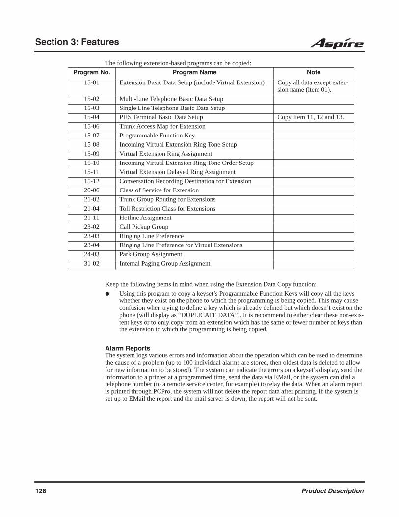
Section 3: Features
The following extension-based programs can be copied:
Keep the following items in mind when using the Extension Data Copy function:
Using this program to copy a keyset’s Programmable Function Keys will copy all the keys whether they exist on the phone to which the programming is being copied. This may cause confusion when trying to define a key which is already defined but which doesn’t exist on the phone (will display as “DUPLICATE DATA”). It is recommend to either clear these non-exis-tent keys or to only copy from an extension which has the same or fewer number of keys than the extension to which the programming is being copied.
Alarm ReportsThe system logs various errors and information about the operation which can be used to determine the cause of a problem (up to 100 individual alarms are stored, then oldest data is deleted to allow for new information to be stored). The system can indicate the errors on a keyset’s display, send the information to a printer at a programmed time, send the data via EMail, or the system can dial a telephone number (to a remote service center, for example) to relay the data. When an alarm report is printed through PCPro, the system will not delete the report data after printing. If the system is set up to EMail the report and the mail server is down, the report will not be sent.
Program No. Program Name Note
15-01 Extension Basic Data Setup (include Virtual Extension) Copy all data except exten-sion name (item 01).
15-02 Multi-Line Telephone Basic Data Setup
15-03 Single Line Telephone Basic Data Setup
15-04 PHS Terminal Basic Data Setup Copy Item 11, 12 and 13.
15-06 Trunk Access Map for Extension
15-07 Programmable Function Key
15-08 Incoming Virtual Extension Ring Tone Setup
15-09 Virtual Extension Ring Assignment
15-10 Incoming Virtual Extension Ring Tone Order Setup
15-11 Virtual Extension Delayed Ring Assignment
15-12 Conversation Recording Destination for Extension
20-06 Class of Service for Extension
21-02 Trunk Group Routing for Extensions
21-04 Toll Restriction Class for Extensions
21-11 Hotline Assignment
23-02 Call Pickup Group
23-03 Ringing Line Preference
23-04 Ringing Line Preference for Virtual Extensions
24-03 Park Group Assignment
31-02 Internal Paging Group Assignment
128 Product Description

Section 3: Features
3
The alarm reports indicate:
System start-up/upgrade date and time PCB communication error with the date and time and the restoration date and time Date and time a PCB was removed from the system Date and time an extension was disconnected from the system Date and time of any interruption in system power Power brown-outs generate a Low Battery log Hard disk driver exchange time is logged (Future Item) Date and time of any system data change
System InformationThe system can print a report of the PCBs installed, the port assignments, and the port types. This information is sent to the port defined in Program 90-13.
This report includes:
The version of system software PCB names Slot condition (working, blocked) Port assignment Port classification
Reloading Customer DatabasesWhen reloading a customer database, the system must be reset (either using Program 90-08 or power down/power up) before all uploaded programming will take affect.
After uploading the programming, reset the system and wait a few minutes for the system to reset completely before accessing any lines or special system features. Otherwise, some unusual LED indications may be experienced.
Meet Me Conference
DescriptionWith Meet Me Conference, an extension user can set up a Conference with their current call and up to 32 other internal or external parties. Each party joins the Conference by dialing a Meet Me Con-ference code. Meet Me Conference lets extension users have a telephone meeting -- without leav-ing the office.
Aspire S Aspire M/L/XL
• NTCPU provides 32 conference circuits, allowing any number of internal or external parties conferenced up to the limit of 32.
• NTCPU provides 2 blocks of 32 conference circuits, allowing each block to have any number of internal or external parties conferenced up to the block’s limit of 32.
Product Description 129
Section 3: Features
Meet Me Paging
DescriptionMeet Me Paging allows an extension user to Page a co-worker and privately meet with them on a Page zone. The Paging zone is busy to other users while the meeting takes place. While the co-workers meet on the zone, no one else can hear the conversation, join in or make an announcement using that zone. Meet Me Paging is a good way to talk to a co-worker when their location is unknown. If the co-worker can hear the Page, they can join in the conversation.
Meet Me Paging Transfer
DescriptionIf a user wants to Transfer a call to a co-worker but they don’t know where the co-worker is, they can use Meet Me Paging Transfer. With Meet Me Paging Transfer, the user can Page the co-worker and have the call automatically Transfer when the co-worker answers the Page. Since Meet Me Paging Transfer works with both Internal and External Paging, a call can be quickly extended to a co-worker anywhere in the facility.
Memo Dial
DescriptionWhile on an outside call, Memo Dial lets a display keyset user store an important number for easy redialing later on. The telephone can be like a notepad. For example, a user could dial Directory Assistance and ask for a client’s telephone number. When Directory Assistance plays back the requested number, the caller can use Memo Dial to jot the number down in the telephone’s memory. They can quickly call the Memo Dial number after hanging up.
When a user enters a Memo Dial number, the dialed digits do not output over the trunk. Dialing Memo Dial digits does not interfere with a call in progress.
Aspire S Aspire M/L/XL
• Available. • Available.
Aspire S Aspire M/L/XL
• Available. • Available.
Aspire S Aspire M/L/XL
• Available. • Available.
130 Product Description

Section 3: Features
3
Message Waiting
DescriptionAn extension user can leave a Message Waiting indication at a busy or unanswered extension requesting a return call. The indication is a flashing MW lamp at the called extension and a steadily lit MW lamp on the calling extension. Answering the Message Waiting automatically calls the extension which left the indication. Message Waiting ensures that a user will not have to recall an unanswered extension. It also ensures that a user will not miss calls when their extension is busy or unattended. Additionally, Message Waiting lets extension users:
View and selectively answer messages left at their extension (display keyset only)
Cancel all messages left at their extension
Cancel messages they left at other extensions
An extension user can leave Messages Waiting at any number of extensions. Also, any number of extensions can leave a Message Waiting at the same extension. A periodic VRS announcement may remind users that they have Messages Waiting.
MSG Key will Operate as Voice Mail KeyThe system enhances a phone’s MSG key function when connected to a system which has voice mail installed. When an extension receives a voice mail, the MSG key can be used to check the number of messages in voice mail, as well as call the voice mail to listen to the messages. If there is no Voice Mail Programmable Function Key defined (Program 15-07-01, code 77), the phone’s Mes-sage Waiting LED will flash to indicate new messages.
This option is not available with a networked voice mail - the voice mail must be local.
Refer to the Voice Mail feature for the feature operation.
LED Color IndicationDepending on your software, the software provides an option allows you to select whether the Mes-sage Wait LED located at the top of the keyset will flash green (0) or red (1) when a Message Wait indication is flashing. By default, this option is set to flash red.
Note that if this LED is also used for voice mail indications (no Programmable Function Key pro-grammed for voice mail), if there are both voice mail messages and Message Wait indications, the color set for Message Wait will override the color used for voice mail indications (red).
Aspire S Aspire M/L/XL
• Available.
• The MSG key as Voice Mail key feature is available.
• LED Color Indication option requires software 2.63+.
• SLT MW Indication option requires software 2.63+.
• Available.
• The MSG key as Voice Mail key feature is available with 1.11+ software.
• LED Color Indication option requires software 2.63+.
• SLT MW Indication option requires software 2.63+.
Product Description 131
Section 3: Features
Single Line Telephone MW Indication OptionAn option is available for analog single line telephones which provide a display. When a user leaves a Message Waiting for a SLT which has a display, Program 15-03-13 : Single Line Telephone Basic Data Setup - MW Signal Type is used to determine whether the SLT user will see a MW LED indication or if the Caller ID will be used to display the call.
Microphone Cutoff
DescriptionMicrophone Cutoff lets a keyset user turn off their phone’s handsfree or handset microphone at any time. When activated, Microphone Mute prevents the caller from hearing conversations in the user’s work area. The user may turn off the microphone while their telephone is idle, busy on a call or ringing. The microphone stays off until the user turns it back on.
Multiple Directory Numbers / Call Coverage
DescriptionMultiple Directory Numbers let a keyset have more than one extension number. Calls can route to the keyset’s installed number or to the keyset’s “virtual extension” Multiple Directory Number key. This helps users identify incoming calls. For example, an extension installed at 304 (Sales) could have a virtual extension for 460 (Service). Calls to 304 ring the extension normally. Calls to 460 ring the Multiple Directory Number key. This lets the user at extension 304 differentiate Sales calls from Service calls.
Call CoverageA keyset can have Multiple Directory Number keys set up as Call Coverage keys for co-worker’s extensions. The Call Coverage key lights when the co-worker’s extension is busy and flashes slowly when the co-worker has an incoming call. The Call Coverage key can ring immediately when a call comes into the covered extension, ring after a delay or not ring at all. In addition, the keyset user can press the Call Coverage key to intercept their co-worker’s incoming call. The user can also go off hook and press the Call Coverage key to call the covered extension.
If the covered extension is busy and they receive a second call, the covering extension’s Call Cover-age key will flash. The user just presses the flashing key to pick up the call.
Aspire S Aspire M/L/XL
• Available. • Available.
Aspire S Aspire M/L/XL
• Available - Virtual ports 1-24.
• Virtual extensions can use Fixed Call Forward Off-Premise with CO trunks.
• Available - Virtual ports 1-256.
• Virtual extensions can use Fixed Call Forward Off-Premise with CO trunks.
132 Product Description

Section 3: Features
3
The Call Coverage keys follow the extension’s Do Not Disturb and Off-Hook Signaling program-ming. These keys do not, however, indicate the lamping for extensions in DND. If this is required, a Hotline key can be used instead.
Place and Receive Calls on Call Coverage/Multiple Directory Number KeysMultiple Directory Number keys/Call Coverage keys can be used three separate ways, depending on how the key is defined in Program 15-02-21.
a DSS key to the extension and for receiving incoming calls answering incoming calls with the ability to place outgoing ICM or CO calls
OR
just for receiving incoming calls
A keyset can have Multiple Directory Number/Call Coverage keys for many different extensions and virtual extensions. In addition, co-workers can share the same Multiple Directory Numbers. For example, everyone in the Service Department could have a key for the Sales Department’s vir-tual extension.
Auto Off-Hook Answer and Ringing Line Preference for Call Coverage KeysAn extension’s Call Coverage Keys can be programmed to allow the user to simply pick up the handset to answer a ringing call. So as not to interfere with ringing trunk or Intercom calls, the sys-tem automatically assigns Call Coverage Key ringing with the lowest answering priority. If multi-ple Call Coverage Keys are ringing, answering priority is set first by the assigned ring pattern and then by the key position.
Virtual Extension vs. Ring GroupsAs the system does not allow voice mail calls to ring Ring Groups, a virtual extension can be cre-ated which will allow you to direct more than one call to the extension. The system will allow up to 10 calls to be queued. When you program a Call Coverage Key for that extension to ring, the next call can then be answered.
This could allow a voice mail caller to dial the virtual extension and have all the extensions with the same virtual extension key ring. The system can be programmed as follows:
Program 11-04, 15-01-01: Assign a virtual extension number and name (example: virtual port 1, extension 5400, Sales, virtual port 2, extension 5401, Customer Service, etc.).
Program 11-07: Assign a Department Group Pilot number for the virtual extension (exam-ple: Department Group Number 2 = 5555).
Program 15-07: Assign a Call Coverage key (*03) to an extension for the virtual extension number assigned.
Program 16-02: Department Group Assignment for Virtual Extensions (example: virtual extension 5400 - group 2, virtual extension 5401 - group 2).
The end user can then simply transfer the call to the virtual extension number (example: 5555). The call is in placed in queue and will be answered in turn as soon as the extension is available.
Call Forward Off-Premise From CO Trunk/Voice Mail Transfer PossibleThe system allows virtual extensions to use Fixed Call Forward Off-Premise with normal central office trunks. With some older software, this was only possible using DIL or DID trunks. This enhancement allows a call transferred by the voice mail to a virtual extension to be forwarded off-premise.
Product Description 133

Section 3: Features
Music on Hold
DescriptionMusic on Hold (MOH) sends music to calls on Hold and parked calls. The music lets the caller know that his call is waiting, not forgotten. Without Music on Hold, the system provides silence to these types of calls. The Music on Hold source can be internal (synthesized) or from a customer-provided music source (i.e., tape deck, receiver, etc.). The customer-provided source can connect to a PGDAD module analog port or to a connector on the CPRU PCB.
Option Available for Using System ToneThe Music on Hold feature has been enhanced to allow callers to hears a system tone instead of playing the internal or external music.
Note: In accordance with U.S. copyright law, a license may be required from the American Society of Composers, Authors and Publishers (ASCAP) or other similar organizations, if radio, television broadcasts or music other than material not in the public domain are transmitted through the Music on Hold feature of telecommunications systems. NEC America hereby disclaims any lia-bility arising out of the failure to obtain such a license.
Name Storing
DescriptionExtensions and trunks can have names instead of just circuit numbers. These names show on a key-set’s display when the user places or answers calls. Extension and trunk names make it easier to identify callers. The user does not have to refer to a directory when processing calls. A name can be up to 12 digits long, consisting of alphanumeric characters, punctuation marks and spaces.
Additional Characters AvailableWhen using the Name Storing feature, the system now provides additional characters which can be used. These characters are available with any option which allows Name Storing - Abbreviated Dialing, One-Touch Keys, Extension Name, Trunk Naming.
Aspire S Aspire M/L/XL
• Available.
• Using a system tone for MOH requires software 2.63+.
• Available.
• Using a system tone for MOH requires software 2.63+.
Aspire S Aspire M/L/XL
• Available.
• Additional characters available.
• Available.
• Additional characters added in software 2.05+.
134 Product Description

Section 3: Features
3
Under key 1:
Under key 0:
Under key *:
With this change, to enter a space or accept an entry, the # key is used. However, this key will only work when performing user programming (such as Name Storing for an extension, service code 800). When in system programming, the right arrow soft key must be used to advance the cursor.
Networking
Description
Á À Â Ã Ç É Ê ì ó
ô Õ ú ä ö ü a e θ
π ∑ σ Ω ∞ ¢ £
Aspire S Aspire M/L/XL
• Networking with VoIP or BRI available. PRI Network-ing is not available.
• Keep Alive options added with software 1.11+.
• PRI Channel Limitation is not available.
• Transfer Network trunk to local voice mail using voice mail key requires software 3.05+.
• Two System Networking available with software 1.07+.
• Multiple Site Networking available with software 2.08+.
• This feature requires the Basic NTCPU (P/N 0891002) with the PAL upgrade or the Enhanced NTCPU (P/N 0891038).
• Keep Alive options added with software 1.11+.
• PRI Channel Limitation added with software 2.09+.
• Transfer Network trunk to local voice mail using voice mail key requires software 3.05+.
Product Description 135

Section 3: Features
Use the built in networking feature to integrate multiple phone systems into a single “virtual” com-munications system. Interconnected with ISDN PRI or BRI or VoIP, each phone system becomes a node on the network that can communicate with any other phone system node.
Centralized Network Attendant Centralized Network Attendant allows multiple networked systems to share a single central-ized attendant. This centralized attendant can receive calls from and transfer calls to any desti-nation in any network node. Unanswered calls recall and route as if they were part of a single, much larger system. Currently, only the use of an external voice mail is supported for cen-tralized voice mail.
Flexible Network RoutingUse network routes to set up ISDN and VoIP networking between many separate systems - or use mixed (ISDN or VoIP) networking per system for greater network performance. Data tables in the system program define the routing for each network node. These tables are easily customized to meet the requirements of each networking configuration.
Users may place an intercom call or transfer a call to any extension at any location by simply dialing an extension number. The system analyzes each extension number received and deter-mines how to route the call to its final destination. The feature which handles this route selec-tion is called Flexible Routing (F-Routing). F-Routing also has the ability to select alternate routes to the destination extension if the primary destination is busy. Up to 48 routes are avail-able for networking. Once an extension number is dialed, the system checks the routing, accesses the assigned trunk group and places the call. Each extension is assigned a route or routes that decides which trunk group to access and any modified dialed data if required.
PRI Networking With Two Local Voice Mails, Masters Must Have Different NumberingWhen programming a PRI network with each system having their own local voice mail, the master numbers for the voice mails must be defined in different series in Program 11-01. The second digit of the extension number can not be the same. For example, 700 and 701 will not work, however 700 and 710 can be used.
With Two Local Voice Mails, Network ID Must Match in Programming
With a networked system, with each system having their own voice mail. The system must be pro-grammed correctly in order for users to properly connect to the correct voice mail when leaving a message. Refer to the Aspire Software Manual for details.
Multiple Site Networking AvailableIP Networking allows for a maximum of 50 nodes. With ISDN Networking, the maximum number of nodes depends on the type of trunks used - PRI, BRI or a mixture of both. As the Aspire M/L/XL is limited to 8 PRI PCBs, when PRI trunks are used, the limit would be 8 systems, but each system would require 8 PRI PCBs. PRI Networking is not available with the Aspire S.
The recommended connection for multiple system Networking is to interconnect all the systems using hardware (required with ISDN Networking) and programming. This also allows such features as Park to be used in a network.
With VoIP Networking, the system IDs for each networked system are defined in Program 10-27 : IP System ID. An IP address is defined for each node, and using the Numbering Plan (Program 11-01xx), the dialed digits are analyzed, the system ID is determined, and the call is routed to the net-worked system.
136 Product Description

Section 3: Features
3
With ISDN Networking, interconnecting the systems is accomplished by defining a master PCB and slave PCB between each system (Program 10-03-10 : PCB Setup - Master/Slave System). Each system must have an ISDN PCB for each other system in the network.
The networked systems can be interconnected using a combination of PRI and VoIP trunks. In this type of setup, the IP resources will received priority over the PRI resources. The PRI will be used when the IP resources are busy. The following two graphics indicate correct networking layouts. Each one provides connection between all three systems within the network.
ISDN Networking Clock SourceWhen using ISDN Networking (PRI or BRI) on the Aspire system, the option selected in Program 10-03-01 : PCB Setup - ISDN Line Mode determines the clock source for the networked connec-tion. The following information indicates how, with each option, the clock source is obtained for the networked systems.
Option 3: Network Mode (Leased Line)Telco sends the clock to the Master SystemTelco sends the clock to the Slave System
Option 4: Network Mode (Interconnected Line)Master System sends the clock to the Telco (or direct connection without telco) which then sends the clock to the Slave System
Option 5: (Interconnected Line, Fixed Layer 1=NT)Master System sends the clock to the TelcoSlave System sends the clock to the Telco
Keep Alive Programs AddedTwo options in Program 10-31 for use with the Networking feature are available to define the inter-val of Keep Alive and how many times the system resends Keep Alive.
PRI Channel LimitationThe system provides an option which can be used to assign the number of B-channels to be used for each ISDN PCB. This allows for fractional PRIs when used with multiple site networking. If this program is limited to less than "23" on one side of the network, then it also limits both inbound and outbound network calls. This also applies on the other side of the network as well.
Transfer Network Trunk to Local Voice Mail Using Voice Mail KeyWith older software, IP or PRI network sites that had their own voice mail could not transfer a call into voice mail using the following steps if the inbound call originated in another site (for example, a call comes in to Site A and it translates to an extension at Site B):
HOLD + the Voice Mail Programmable Function Key (Program 15-07 or SC 851 + 77) or MSG key (Program 15-02-26=1) + the extension number.
Using software 3.05 or higher, this operation is now possible. Keep the following in mind when using this option:
Note that if you have a local and central voice mail, you can not have the same mailbox number at each node. If both sites have the same mailbox, when transferring a call, it will be transferred into the local voice mail and not across the network.
As this software change allows transferring to a general message by a Single Line Set, the fol-lowing two operations have different results between Networking Call Transfer and Internal Call Transfer.- Hold + Voice Mail Master Dial then hang up.- Hold + Service Code (Own Mailbox Access - *8) then hang up.
For additional information on Networking, refer to the Aspire Networking Guide (P/N 0893207).
Product Description 137

Section 3: Features
Night Service
DescriptionNight Service lets system users activate one of the Night Service modes. Night Service redirects calls to their night mode destination, as determined by Assigned and Universal Night Answer pro-gramming. The system allows Night Service to be enabled for each Night Service group, allowing each group to determine when their calls should switch modes. A user typically activates Night Service after normal working hours, when most employees are unavailable to answer calls. The system also provides external contacts to enable Night Service.
There are eight Night Service modes:
Day 1 / Day 2 Modes - for normal working hours
Night 1 / Night 2 Modes - after hours (usually evening)
Midnight 1 / Midnight 2 Modes - late at night to early in the morning
Rest 1 / Rest 2 Modes - interval usually used for lunch
Assigned Night Answer (ANA)With Assigned Night Answer, Night Service has calls ring extensions directly. Assigned Night Answer provides an answering point for Night Service calls. For certain applications, this may be more appropriate than Universal Night Answer. For example, you could program trunks to ring the security station telephone during off hours.
Universal Night Answer (UNA)Universal Night Answer makes incoming calls ring over the External Paging speakers. With UNA, an employee can go to a telephone and press the flashing line key or use “Universal Answer” to pick up the call. Only ring groups calls can be used with Universal Night Answer. For more on set-ting up Universal Answer, turn to the “Central Office Calls, Answering” feature.
You may also be able to use Transfer to UNA. An extension user can Transfer their call to UNA (i.e., External Paging at night). Once transferred, the call will ring the External Paging speakers like any other UNA call and can be picked up at any extension. You can also set up Transfer to UNA through the VRS. This lets outside callers, answered by the VRS, dial a code to have their call ring External Paging.
Automatic Night ServiceThe system will allow or deny Automatic Night Service based on the extension’s class of service pro-gramming. If allowed, the calls will then route according to the service patterns programmed. The Night Service programming is stored in the RAM memory. This means that if the system is not using the Automatic Night Service, in the case of a power failure while in night mode, when the power is restored, the system will continue to be in night mode.
Aspire S Aspire M/L/XL
• Available - 4 Night Service Patterns/Groups.
• Toggle night modes with Programmable Function Key requires software 2.63+.
• Available - 32 Night Service Patterns/Groups.
• Toggle night modes with Programmable Function Key requires software 2.63+.
138 Product Description

Section 3: Features
3
Programmable Function Key Can Toggle Night ModesThe software allows a Night Service Programmable Function Key (PGM 15-07 or SC 851: 09 + 0) to toggle night modes. You can determine in programming how many modes through which the user will toggle. Note that the additional data for the Programmable Function Key must be set to "0" for the toggle function to work.
Off Hook Signaling
DescriptionWhen a user calls an extension busy on a call, they can send an off hook signal through the handset and through the telephone’s speaker indicating they are trying to get through. The signal is an off hook ringing over the idle (second) line appearance. Off Hook Signaling helps important callers get through, without waiting in line for the called extension to become free. The system provides the following Off Hook Signaling options:
Called Extension Block The called extension’s Class of Service may block incoming Off Hook Signaling attempts. This is beneficial to users that don’t want interruptions while on a call.
Automatic SignalingCalling a busy extension automatically initiates Off Hook Signaling. This option is useful to receptionists, operators and others that must quickly process calls. This is set in the called extension’s Class of Service.
Manual SignalingAfter reaching a busy extension, manual signaling gives the caller the choice of using Off Hook Signaling or activating other features. Extension’s without automatic signaling have manual signaling. The users can dial a service code or press a Programmable Function Key to send Off Hook Signaling to the called phone.
Selectable Off Hook Signaling ModeThe Off Hook Signal can be muted ringing, no off hook ringing or a beep in the handset - based on the caller’s programming.
Off Hook RingingUse this option to enable or disable an extension’s Off Hook Signaling for incoming calls. If enabled, Off Hook Signaling occurs normally. If disabled, calls queue behind the extension’s busy line appearance and the user gets no Off Hook Signaling indication. The second line appearance stays idle. The caller hears ringback tone while their call waits. This is set in the called extension’s Class of Service.
DID Call WaitingAn extension can optionally have DID calls camp on with Off Hook/Call Wait signaling, with-out Off Hook/Call Wait signaling or no signaling. This is set in the called extension’s Class of Service.
Block Manual Off Hook SignalsThis Class of Service option enables/disables a busy extension’s ability to block off hook sig-nals manually sent from a co-worker. If disabled (not blocked), callers can dial 7 at busy or busy/ring to signal the extension. If enabled (blocked), nothing happens when the caller dials 7 to off hook signal.
Aspire S Aspire M/L/XL
• Available. • Available.
Product Description 139
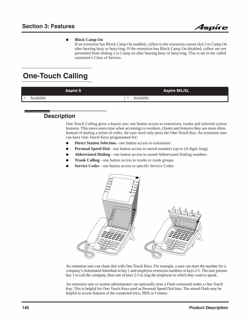
Section 3: Features
Block Camp OnIf an extension has Block Camp On enabled, callers to the extension cannot dial 2 to Camp On after hearing busy or busy/ring. If the extension has Block Camp On disabled, callers are not prevented from dialing 2 to Camp on after hearing busy or busy/ring. This is set in the called extension’s Class of Service.
One-Touch Calling
DescriptionOne-Touch Calling gives a keyset user one button access to extensions, trunks and selected system features. This saves users time when accessing co-workers, clients and features they use most often. Instead of dialing a series of codes, the user need only press the One-Touch Key. An extension user can have One-Touch Keys programmed for:
Direct Station Selection - one button access to extensions
Personal Speed Dial - one button access to stored numbers (up to 24 digits long)
Abbreviated Dialing - one button access to stored Abbreviated Dialing numbers
Trunk Calling - one button access to trunks or trunk groups
Service Codes - one button access to specific Service Codes
An extension user can chain dial with One-Touch Keys. For example, a user can store the number for a company’s Automated Attendant in key 1 and employee extension numbers in keys 2-5. The user presses key 1 to call the company, then one of keys 2-5 to ring the employee to which they want to speak.
An extension user or system administrator can optionally store a Flash command under a One-Touch Key. This is helpful for One-Touch Keys used as Personal Speed Dial bins. The stored Flash may be helpful to access features of the connected telco, PBX or Centrex.
Aspire S Aspire M/L/XL
• Available. • Available.
0893
200
- 5
123
45
6789
10
1 2 3 4 56 7 8 9 10
140 Product Description
Section 3: Features
3
Operator
DescriptionWhen an extension user dials “0”, calls are routed to a main system operator. The operator can answer and route outside calls or locate employees using the Page feature.
OPX (Off Premise Extension)
Refer to the Single Line Telephones, Analog 500/2500 Sets (page 154) for information on this feature.
Paging, External
DescriptionWith External Paging, a user can broadcast announcements over paging equipment connected to external Paging zones. When a user pages on of these external zones, the system broadcasts the announcement over the speakers. Like Internal Paging, External Paging allows a user to locate another employee or make an announcement without calling each extension individually.
The Aspire S system allows up to eight External Paging zones. The Aspire M/L/XL system allows up to nine External Paging zones, with the additional zone (#9) provided on the NTCPU. All other zones (#1-8) requires a port on a 2PGDAD module, with a maximum of two external paging cir-cuits per module. You must have four 2PGDAD modules to get the eight external zones. In addi-tion, each external zone has an associated relay contact. When a user pages to a zone, the corresponding contact activates (closes). This provides for Paging amplifier control. Refer to the system hardware manual for additional details.
Aspire S Aspire M/L/XL
• Available - up to 8 operators. • Available - up to 8 operators.
Aspire S Aspire M/L/XL
• Available - 8 External Paging zones. • Available - 8 External Paging zones.
Product Description 141

Section 3: Features
Combined Paging Use Combined Paging when you want to simultaneously Page into an internal and corresponding external zone. For example, you can Page your company’s warehouse and outside loading dock at the same time. Combined Paging is available for zones 1-8 and All Call. Refer to Paging, Internal (page 142) for more on setting up Combined Paging. In addition, you can program a Function Key as a Combined Paging key. Using the External Page Function Key, when an All Call External Page Function Key is programmed, it will include both the external zones and the assigned internal zone(s). If the internal page zone is busy or there are no extensions in a page group, the announce-ment will be made on the external zones only.
Remove Paging Information from Display PhonesA Class of Service option is available in system programming to prevent display telephones from showing incoming paging information. This allows the system to save processor time and speed up system operation.
Paging, Internal
DescriptionInternal Paging lets extension users broadcast announcements to other keyset users. When a user makes a Zone Paging announcement, the announcement broadcasts to all idle extensions in the zone dialed. With All Call Paging, the announcement broadcasts to all idle extensions programmed to receive All Call Paging. An extension can be a member of only one Internal Paging Zone. Like External Paging, Internal Paging allows a user to locate another employee or make an announce-ment without calling each extension individually.
Combined Paging Use Combined Paging when you want to simultaneously Page into an internal and corresponding external zone. For example, you can Page your company’s warehouse and outside loading dock at the same time. Combined Paging is available for Paging zones 1-8 and All Call. Optionally, you can change the Combined Paging assignments. For example, you can associate External Paging Zone 1 with Internal Paging Zone 4. You can program a Function Key as a Combined Paging key. When an All Call External Page Function Key is programmed, it will include both the external zones and the assigned internal zone(s). If the internal page zone is busy or there are no extensions in a page group, the announcement will be made on the external zones only.
Remove Paging Information from Display PhonesA Class of Service option is available in system programming to prevent display telephones from showing incoming internal paging information. This allows the system to save processor time and speed up system operation.
Aspire S Aspire M/L/XL
• Available - 8 Internal Paging Groups (Zones). • Available - 64 Internal Paging Groups (Zones).
142 Product Description

Section 3: Features
3
Paging, Privacy Release
Please refer to Conference, Voice Call/Privacy Release (page 89) for information on this feature.
Park
DescriptionPark places a call in a waiting state (called a Park Orbit) so that an extension user may pick it up. There are two types of Park: System and Personal. Use System Park when you want to have the call wait in a system orbit. Personal Park allows a user to Park a call at their extension so a co-worker can pick it up. After parking a call in orbit, a user can Page the person receiving the call and hang up. The paged party dials a code or presses a programmed Park key to pick up the call. With Park, it is not nec-essary to locate a person to handle their calls. A call parked for too long will recall the extension that initially parked it, however the call remains in the park orbit until it’s answered. There are 64 Park Orbits (1-64) available for use.
Enhanced Dial BufferingThe system can optionally provide additional dial buffering. In certain high traffic sites, (e.g., with a high volume of dialed paging and parking), standard dial buffering can occasionally lose digits that a user dials. By enabling enhanced buffering, an additional level of buffering occurs which helps ensure that the system processes all digits a user dials.
Splitting Between Parked CallsA keyset user can retrieve two calls from Park Orbit (for which they don’t have line appearances) and easily split (alternate) between them. The split operation brings the calls to the user’s telephone and frees up the Park Orbits.
Extended ParkAn extension’s Class of Service determines whether it will use the normal Park Orbit Recall time or the Extended Park Orbit Recall time. The timers are set up in system programming. When an exten-sion with Extended Park Recall Class of Service option parks a call, it recalls after the Extended Park Orbit Recall time. When an extension with the Normal Park Orbit Recall Class of Service option parks a call, it recalls after the normal Park Orbit Recall time, however the call remains in the park orbit until it’s answered.
Aspire S Aspire M/L/XL
• Available - 64 System Park orbits.
• Personal Park Programmable Function Key and Service Code requires software 2.65+.
• Available - 64 System Park orbits.
• Personal Park Programmable Function Key and Service Code requires software 2.65+.
Product Description 143

Section 3: Features
Programmable Function Key and Service Code Available for Personal ParkThe Personal Park feature is enhanced with the ability to use a Programmable Function Key or ser-vice code (3-digit or 1-digit) to place a call in Personal Park. Older software only provides the option to place a call in Personal Park using a 3-digit service code. With this ability, two new pro-gram options have been added to the system in Program 11-16-11 and 15-07-01. This option is available for keysets, single line sets, and Aspire Wireless telephones and can be used for analog or ISDN trunks.
With this feature, the following conditions apply:
An extension can have only one Personal Park key.
When the terminal that has a call in Personal Park is unplugged, the Personal Park will be released and the held caller will receive busy tone.
The following table indicates what condition the service codes and Programmable Function key can be used.
PBX Compatibility
DescriptionYou can connect your phone system trunks to Centrex/PBX lines, rather than to telco trunk circuits. This makes the trunk inputs into the system 500/2500 type compatible Centrex/PBX extensions, rather than telco circuits. PBX Compatibility lets the system be a node (i.e., satellite) in a larger private telephone network. To place outside calls when the system is behind a PBX, phone system users must first dial the PBX’s trunk access code (usually 9).
The system provides the following PBX Compatibility options:
PBX Trunk Access Code Screening The system can monitor the numbers users dial and screen for PBX trunk access codes. The system can screen for up to 4 groups of trunk access codes. The codes can be one or two dig-its long, consisting of the digits 0-9, # and *. (You use Line Key 1 as a wild card entry.)
Status Using 3-Digit Service Code
Using 1-Digit Service Code
Using Personal Park Key
Speaking Not Available Not Available Available
ICM Dial Tone or Busy Tone Available Not Available Available
Calling Another Extension Available Available(with outside call on hold and when called extension does not answer)
Available
Receiving a Personal Park Recall Available Not Available Available
Aspire S Aspire M/L/XL
• Available. • Available.
144 Product Description

Section 3: Features
3
PBX Trunk Toll RestrictionThe system can provide the Toll Restriction for the PBX trunk, or restriction can be handled solely by the connected PBX. If the phone system provides the restriction, it restricts the dig-its dialed after the PBX access code.
PBX Call RestrictionWhen the phone system does the Toll Restriction, it can further restrict users from dialing PBX extensions. In this case, the only valid numbers are those dialed after the PBX trunk access code. The only PBX facility phone system users can access are the PBX’s outside trunks.
Automatic PauseThe system automatically pauses when it sees a PBX trunk access code during manual dial-ing, Abbreviated Dialing, Last Number Redial, Repeat Redial and Save Number Dialed. This gives the connected PBX time to set up its trunk circuits.
Prime Line Selection
DescriptionPrime Line Selection allows a keyset user to place or answer a call over a specific trunk by just lift-ing the handset. The user does not have to first press keys or dial codes. This simplifies handling calls on a frequently used trunk. Prime Line Selection has the following two modes of operation:
Outgoing Prime Line Preference Lifting the handset seizes the Prime Line. Outgoing Prime Line Preference would help a telemarketer who always needs a free line to call prospective clients. The telemarketer just lifts the handset and the Prime Line is always available. (Outgoing Prime Line Preference may be affected by Incoming Prime Line Preference.)
Incoming Prime Line Preference When the Prime Line rings the extension, lifting the handset answers the call. Incoming Prime Line Preference could benefit the Service Department dispatcher who must quickly answer customer’s service calls and then dispatch repair technicians. The dispatcher would have the assurance than whenever a customer calls in, the dispatcher just lifts the handset get their call. (Incoming Prime Line Preference can optionally seize an idle line appearance.)
Aspire S Aspire M/L/XL
• Available. • Available.
Product Description 145

Section 3: Features
Private Line
DescriptionA Private Line is a trunk reserved for a keyset for placing and answering calls. A user with a Pri-vate Line always knows when important calls are for them. Additionally, the user has their own trunk for placing calls that is not available to others in the system.
Incoming only The keyset has a Private Line only for incoming calls. The user cannot place calls on the Pri-vate Line.
Outgoing onlyThe keyset has a Private Line only for outgoing calls. The Private Line does not ring for incoming calls.
Both ways The keyset has a Private Line for both incoming and outgoing calls.
Programmable Function Keys
DescriptionEach keyset has Programmable Function Keys. Programmable Function Keys simplify placing calls, answering calls and using certain features. You can customize the function of a keyset’s pro-grammable keys from your administration telephone, or the extension user can do it themselves. Depending on your telephone style, you can have either 12 or 24 Programmable Function Keys.
Aspire S Aspire M/L/XL
• Available. • Available.
Aspire S Aspire M/L/XL
• Available. • Available.
146 Product Description

Section 3: Features
3
Pulse to Tone Conversion
DescriptionAn extension can use Pulse to Tone Conversion on trunk calls. Pulse to Tone Conversion lets a user change their extension’s dialing mode while placing a call. For systems in a Dial Pulse area, this permits users to access dial-up OCCs (such as MCI) from their DP area. The user can, for example:
Place a call to an OCC over a DP trunk.
Depending on programming: Manually implement Pulse to Tone Conversion
OR Wait 10 seconds.
Dial the OCC security code and desired number. The system dials the digits after the conver-sion as DTMF.
Repeat Redial
DescriptionIf a keyset user places a trunk call that is busy or unanswered, they can have Repeat Redial try it again later on. The user doesn’t continually have to try the number again -- hoping it will go through. Repeat Redial automatically retries it until the called party answers (the number of retries is based on system programming).
Aspire S Aspire M/L/XL
• Available. • Available.
Aspire S Aspire M/L/XL
• Available. • Available.
Product Description 147

Section 3: Features
Reverse Voice Over
DescriptionWhile on a handset call, Reverse Voice Over lets a busy keyset user make a private Intercom call to an idle co-worker. The idle co-worker can be at a keyset or 500/2500 set. The busy user just presses and holds down a programmed Reverse Voice Over key to make a private call to a specified co-worker. The initial caller cannot hear the Reverse Voice Over conversation. The private Intercom call continues until the Reverse Voice Over caller releases the key again. The initial call can be an outside call or an Intercom call.
Reverse Voice Over could help a salesman, for example, when placing a call to an important client. The salesman can talk with the client and give special instructions to a secretary - without interrupting the initial call.
When the keyset is idle, the Reverse Voice Over key functions the same as a Hotline key. A keyset’s Reverse Voice Over key also shows at a glance the status of the associated extension:
Note: When the keyset is idle, the Reverse Voice Over provides one button calling to the associated extension (like a Hotline key). An extension user cannot, however, use the Reverse Voice Over key to Transfer calls.
Ring Groups
DescriptionRing Groups determine how trunks ring extensions. Generally, trunks ring extension’s only if Ring Group programming allows. For example, to make a trunk ring an extension:
Assign the trunk and the extension to the same Ring Group
In the extension’s Ring Group programming, assign ringing for the trunk.
Aspire S Aspire M/L/XL
• Available. • Available.
When the key is. . . The associated extension is. . .
Off Idle
On Busy or call ringing
Fast Flash In Do Not Disturb
Aspire S Aspire M/L/XL
• Available - 8 Ring Groups. • Available - 100 Ring Groups.
148 Product Description
Section 3: Features
3
Any number of extensions and trunks can be in a specific group. The Aspire S system allows Ring Groups=1-8, In-Skin Voice Mail (102), or Centralized Voice Mail (103). The Aspire M/L/XL sys-tem allows Ring Groups=1-100, In-Skin Voice Mail (102), or Centralized Voice Mail (103).
If an extension has a line key for the trunk, Ring Group calls ring the line key. If the extension doesn’t have a line key, the trunk rings the line appearance key. If an extension has a key for a trunk that is not in its ring group, the trunk follows Access Map programming.
Ring Tones, Selectable
Please refer to Selectable Ring Tones (page 153) for information on this feature.
Ringdown Extension, Internal/External
DescriptionWith a Ringdown Extension, a user can call another extension, outside number, or Abbreviated Dialing number by just lifting the handset. The call automatically goes through - there is no need for the user to dial digits or press additional keys. Ringdown Extensions are frequently used for lobby phones, where the caller just lifts the handset to get the information desk or off-site Reservation Desk.
After the Ringdown Extension user lifts the handset, ringdown occurs after a programmable interval. Depending on the setting of this interval, the extension user may be able to place other calls before the ringdown goes through.
The system allows each extension in the system to have a Ringdown Extension. All extensions can share the same dialing number, if desired.
Aspire S Aspire M/L/XL
• Available - 512 Hotline assignments and 50 extensions/virtual extensions with software 2.08-2.21; 66 extensions/virtual extensions with software 2.50 and higher.
• Available - 512 extensions/virtual extensions and 512 Hotline assignments.
Product Description 149

Section 3: Features
Room Monitor
DescriptionRoom Monitor lets an extension user listen to the sounds in a co-workers area. For example, the receptionist could listen for sounds in the warehouse when it’s left unattended. To use Room Moni-tor, the initiating extension and the receiving extension must activate it.
When using keysets for monitoring, an extension user can only Monitor one extension at a time. However, many extensions can Monitor the same extension at the same time.
With single line phones, multiple SLTs can be programmed to be monitored by the same SLT. How-ever, only one SLT can monitor another SLT at a time.
Room Monitor for Single LinesThis option enables you to monitor the room status through your single line telephone. Between keysets, the monitored room status is picked up by the phone’s microphone and the activity is heard through the speaker of the monitoring keyset. Between single line phones, a user goes off hook on the monitored phone and, from another single line phone, dials a service code and the extension number. The activity of the area where the monitored phone is placed can then be heard at the mon-itoring phone. This service is available until the handset of the monitored telephone is placed on hook.
Aspire S Aspire M/L/XL
• Available. • Available.
CAUTION
The use of monitoring, recording, or listening devices to eavesdrop, monitor, retrieve, or record telephone conversation or other sound activities, whether or not contemporaneous with transmission, may be illegal in certain circumstances under federal or state laws. Legal advice should be sought prior to implementing any practice that monitors or records any telephone conversation. Some federal and state laws require some form of notification to all parties to a telephone conversation, such as using a beep tone or other notification methods or requiring the consent of all parties to the telephone conversation, prior to monitoring or recording the telephone conversation. Some of these laws incorporate strict penalties.
150 Product Description
Section 3: Features
3
Save Number Dialed
DescriptionSave Number Dialed permits an extension user to save their last outside number and easily redial it later on. For example, an extension user can recall a busy or unanswered number without manually dialing the digits. The system retains the saved number until the user stores a new one in its place.
Save Number Dialed saves in system memory a dialed number up to 24 digits. The number can be any combination of digits 0-9, # and *. The system remembers the digits regardless of whether the call was answered, unanswered or busy. The system normally uses the same trunk group as for the initial call. However, the extension user can preselect a specific trunk if desired.
Secretary Call (Buzzer)
DescriptionSecretary Call lets two co-workers alert each other without disturbing their work. To have Secretary Call, both co-workers must have keysets with Secretary Call buzzer keys. When a user presses their buzzer key, the system alerts the called extension by sending a splash tone and flashing the called extension’s buzzer key. The called user can respond by placing an Intercom call to the calling party. The called extension’s buzzer key continues to flash and the splash tone is heard until either user can-cels the Secretary Call. A secretary could use this feature, for example, to get a message through to the boss in an important meeting. After being alerted, the boss could call the secretary when it’s most convenient.
An extension can have Secretary Call keys for any number of extensions, limited only by the avail-able number of programmable keys.
Aspire S Aspire M/L/XL
• Available. • Available.
Aspire S Aspire M/L/XL
• Available. • Available.
Product Description 151
Section 3: Features
Secretary Call Pickup
DescriptionSecretary Call Pickup lets a keyset user easily reroute calls intended for a co-worker to themselves. By pressing a Secretary Call Pickup key, the user can have all calls to a co-worker’s phone ring or voice-announce theirs instead. Secretary Call Pickup is a simplified type of Call Forward with Follow Me for employees that work closely together. This feature could be helpful to customer service representatives that must frequently cover each other’s clients. When a representative leaves their desk, an associate could press the Secretary Call Pickup key to intercept all their calls.
An extension can have Secretary Call Pickup keys for any number of extensions, limited only by the available number of programmable keys.
Selectable Display Messaging
DescriptionAn extension user can select a preprogrammed Selectable Display Message for their extension. Display keyset callers see the selected message when they call the user’s extension. Selectable Dis-play Messaging provides personalized messaging. For example, an extension user could select the message “GONE FOR THE DAY”. Any display keyset user calling the extension may hear a DND signal and then see the message. See table below for a list of the standard messages.
An extension user can add digits for date, time or phone number after messages 1-8 and 10 (up to 24 characters). For example, an extension user could select the message “ON VACATION UNTIL” and then enter the date. Callers see the original message followed by the appended date. They would then be able to tell when the user was coming back from vacation. The system allows all phones to use the Selectable Display Messaging feature at the same time.
Aspire S Aspire M/L/XL
• Available. • Available.
Aspire S Aspire M/L/XL
• Available - all telephones are able to use Selectable Dis-play Messaging at one time.
• Available - all telephones are able to use Selectable Dis-play Messaging at one time..
152 Product Description

Section 3: Features
3
The default messages are:
Selectable Ring Tones
DescriptionAn extension user can change the way trunks or ICM calls ring their phone. Selectable Ring Tones allows an extension user to set up unique ringing for their calls. This is important in a crowded work area where several phones are close together. Because their phone has a characteristic ring, the user always can tell when it’s their phone ringing.
Serial Call
DescriptionSerial Call is a method of transferring a call so it automatically returns to the transferring extension. Serial Calling saves transferring steps between users. For example, a Customer Service Representative (CSR) has a client on the phone who needs technical advice. The CSR wants to send the call to Tech Service, but needs to advise the client of certain costs when Tech Service is done. Rather than transfer-ring the call back and forth, the CSR can use Serial Call to Technical Service and announce, “I have Ted on the phone. I need to talk to him again. Just hang up when you’re done and I’ll get him back.”
No. Message Change “#” to...
12345678910
11-20
IN MEETING UNTIL ##:##MEETING ROOM - ########COME BACK ##:##PLEASE CALL ###########BUSY CALL AFTER ##:##OUT FOR LUNCH BACK ##:##BUSINESS TRIP BACK ##/##BUSINESS TRIP ##########GONE FOR THE DAYON VACATION UNTIL ##/##MESSAGE 11-20
Time (when meeting done)Room Name or extensionTime (when returning)11 digits (phone number)Time (when returning)Time (when returning)Date (when returning)10 digits (where reached)
Date (when returning)
Aspire S Aspire M/L/XL
• Available. • Available.
Aspire S Aspire M/L/XL
• Available. • Available.
Product Description 153

Section 3: Features
Single Line Telephones, Analog 500/2500 Sets
DescriptionThe system is compatible with 500 type (Dial Pulse) and 2500 type (DTMF) analog single line tele-phones (SLTs). You can install single line telephones as On-Premise or Off-Premise extensions. Single line telephone users can dial codes to access many of the features available to keyset users. With Single Line Telephones, you can have your system simulate PBX type operation.
When installing single line telephones, you must have:
A port on an SLIU PCB for each single line telephone installed. (If you have 2500 sets) At least one block reserved on the NTCPU for analog extension
DTMF reception.
CODEC Filter Data Setup Program AddedWhen Program 82-07-01 : CODEC Filter Setup for Analog Station Ports is set to "4 - Specified Data", the system will use the settings in Program 82-09 : SLIU CODEC Filter Data Setup.
These values should not be changed from their default settings unless directed by NEC’S Technical Service department.
The side tone of the SLIU is adjusted using all 16 values, however, special software is required in order to compute these values. The setting is not proportional to the gain level. To change these values, contact NEC’s Technical Service department for assistance.
DTMF Dial Out Timer AddedDepending on your software version, Program 20-03-07 is available for DTMF dialing. When the system is programmed to receive all digits before sending (Program 20-03-03=0), the system will follow the timers in Program 20-03-04 and 23-03-07.
The timer in Program 20-03-04 : System Options for Single Line Telephones - Dial Sending Start Time for SLT or ARS will reset when the user dials another digit.
The timer in Program 23-03-07 : System Options for Single Line Telephones - Forced Dial Sending Start Time will not reset when a digit is dialed. The user must finish dialing all the digits before this timer expires.
Aspire S Aspire M/L/XL
• Available - 16 single line telephones maximum.
• Defining CODEC Filter settings available.
• DTMF Dial Out Timer Added with software 4.0E+.
• Available - Aspire M/L: 256 single line telephones maximum (may be restricted due to system power requirements).Aspire XL: 384 single line telephones maximum - requires software 4.0E+.
• Defining CODEC Filter settings available with software 1.04+.
• DTMF Dial Out Timer Added with software 4.0E+.
154 Product Description

Section 3: Features
3
Single Line Telephones, Digital
DescriptionThe digital single line telephone (DSL) can be installed as On-Premise or Off-Premise extensions. Single line telephone users can dial codes to access many of the features available to keyset users. With single line telephones, you can have your system simulate PBX type operation. Each single line telephone installed must have a port on an ESIU PCB.
Soft Keys
Description
Each display telephone provides interactive soft keys for intuitive feature access. It is no longer necessary to remember feature codes to access the telephone’s advanced features because the func-tion of the soft keys change as the user processes calls. For example, just press a soft key to Page, Park a call, leave a message or Camp On to a busy co-worker.
Additional options allow you to “fine tune” the keyset’s volume levels for handset receive and trans-mit, speaker volume, ringer and handset volume, and headset volume levels. You can also customize the point at which the built-in speakerphone switches from transmit to receive; a boon for noisy envi-ronments. The display telephones also have a contrast control for the LCD display.
Aspire S Aspire M/L/XL
• Available - 24 single line telephones maximum. • Available - Aspire M/L: 256 single line telephones maximum (may be restricted due to system power requirements).Aspire XL: 384 single line telephones maximum - requires software 4.0E+.
Aspire S Aspire M/L/XL
• Available. • Available.
Product Description 155

Section 3: Features
Station Message Detail Recording
DescriptionStation Message Detail Recording (SMDR) provides a record of the system’s trunk calls. Typi-cally, the record outputs to a customer-provided printer, terminal or SMDR data collection device. SMDR allows you to monitor the usage at each extension and trunk. This makes charge-back and traffic management easier.
SMDR provides the following options:
Abandoned Call ReportingThe SMDR report includes calls that rang into the system but were unanswered (i.e., aban-doned). SMDR can include all abandoned calls or only those abandoned calls that rang longer than the specified duration. The Abandoned Call Report helps you keep track of lost business.
Blocked Call ReportingWhen Toll Restriction blocks a call, you can have SMDR print the blocked call information. Or, you can have SMDR exclude these types of calls. With Blocked Call Reporting, you can better customize Toll Restriction for the site’s application.
Customized Date FormatThe SMDR header can show the report date in one of three formats: American, European or Japanese. Set the format for your preference.
Transferred Call TrackingSMDR shows each extension’s share of a transferred call. If an outside call is transferred among four extensions, SMDR shows how long each of the callers stayed on the call.
Data Call TrackingData Call Tracking can log the system’s internal data calls. Since SMDR normally logs exter-nal (trunk) data calls, Data Call Tracking lets you get a complete picture of data terminal activity.
Aspire S Aspire M/L/XL
• Available.
• This feature requires a connection to the system using a CTA or CTU adapter, or through the serial, USB or LAN port on the Aspire NTCPU. (The LAN port only pro-vides information through LAN-capable programs, such as HyperTerminal. Printing of the SMDR information must be done from within that program.)
• Caller ID Added to SMDR Output requires software 4.0E+.
• Available.
• This feature requires a connection to the system using a CTA or CTU adapter, or through the serial or USB port on the Aspire NTCPU.
• The LAN port on the Aspire NTCPU can be used with 1.02+. (The LAN port only provides information through LAN-capable programs, such as HyperTermi-nal. Printing of the SMDR information must be done from within that program.)
• Caller ID Added to SMDR Output requires software 4.0E+.
156 Product Description
Section 3: Features
3
Digit CountingWith Digit Counting, SMDR can selectively keep track of toll calls. For example, if the digit count is nine, SMDR won’t include toll calls within the home area code. Digit Counting per-mits SMDR to include only the types of calls you want to monitor.
Digit MaskingDigit Masking lets you “X” out portions of the number dialed on the SMDR report. A digit mask of seven, for example, masks out all exchange codes (NNXs) and local addresses. Digit Masking makes it easier to keep track of calling patterns, without having to interpret each individual number. You can also use Digit Masking to block out access and security codes.
Duration MonitoringSMDR can include calls of any duration, or only those that last longer than the interval you specify. If you want to keep track of all trunk activity, use a short duration. To keep track of only significant usage, use a longer duration.
Extension ExclusionYou can selectively exclude extensions from the SMDR report. This ensures privacy for high-profile callers. For example, the company attorney negotiating a merger may not want his calls to show up on an in-house report.
PBX Call ReportingIf you system is behind a PBX, you can have SMDR monitor all traffic into the PBX or just calls placed over PBX trunks. The SMDR record can include all PBX calls (including calls to PBX extensions) or just calls that include the PBX trunk access code.
Serial and USB SMDR CommunicationThe system is compatible with both serial and USB SMDR devices. This gives you many SMDR output options. For example, you can output the SMDR report to a high speed printer or send it to disk through a PC’s serial or USB port (requires the USB driver which can be downloaded from the NEC Technical Support web site - ws1.necii.com).
Trunk ExclusionUse Trunk Exclusion to exclude certain trunks not subject to per-call charges (like WATS lines) from the SMDR report. This makes call accounting easier, since you review only those calls with variable costs.
Usage SummariesSMDR can automatically print daily, weekly and monthly call activity summaries. Each sum-mary includes the total number of regular trunk calls and ISDN trunk calls, and the costs for each type. The daily report prints every day at midnight. The weekly report prints every Sun-day night at midnight. The monthly report prints at midnight on the last day of the month.
Extension Name or NumberThe SMDR report can include an extension’s name or extension number. Choose the method that makes it easier for you to track call usage.
Caller ID Added to SMDR OutputThis software enhances the SMDR output to include up to 16 or 24 characters of the Caller ID name information (depending on the view option selected in Program 35-02-18). With the follow-ing new programs/options, you can select to display the Caller ID number or name, or the DID number. If you wish to display the Caller Name in the “DIALLED NO./CLI” and “ACCOUNT" area, select "2" in the updated Program 35-02-15 and "1" in Program 35-02-17.
If the Caller ID name is not received, the area for Caller ID Name is left blank.
Product Description 157

Section 3: Features
r
r
For example, with Program 35-01-09 = 0 (Format for NA) and Program 35-02-17 = 1 (Caller ID Name), if a call is received with the Caller ID Name of “NECinfrontia Corporation” (24 charac-ters), the following SMDR record is displayed:
If Program 35-02-18 = 1 (Caller ID Name Output Method) is set to line feed, the SMDR will dis-play as follows:
Station Park
Please refer to Park (page 143) for information on this feature.
Station Relocation
Please refer to Maintenance (page 125) (Extension Data Swap) for information on this feature.
T1 Trunking (with ANI/DNIS Compatibility)
CLASS TIME DATE LINE DURATION STATION DIALLED No./CLI ACCOUNT
POT 10:52 12/09 002 00:00:10 2001 2142623801 08754
PIN 10:52 12/09 001 00:00:20 2017 2142623802 NECinfrontia Co
PIN 10:53 12/09 002 2142623801 NO ANSWER
CLASS TIME DATE LINE DURATION STATION DIALLED No./CLI ACCOUNT
POT 10:52 12/09 002 00:00:10 2001 2142623801 08754
PIN 10:52 12/09 001 00:00:20 2017 2142623802 NECinfrontia Co
NEXT NECinfrontia Corp.
PIN 10:53 12/09 002 2142623801 NO ANSWER
Aspire S Aspire M/L/XL
• Not Available. • Available
• ANI/DNIS Compatibility is available.
• This feature requires the Basic NTCPU (P/N 0891002) with the PAL upgrade or the Enhanced NTCPU (P/N 0891038) unless using software 4.0E or higher.
158 Product Description
Section 3: Features
3
DescriptionThe T1/PRI Interface PCB gives the system T1 trunking capability. This PCB uses a single univer-sal slot and provides up to 24 trunk circuits. In additional to providing digital-quality trunking, the T1/PRI Interface PCB allows you to have maximum trunking capability with fewer PCBs. This in turn makes more universal slots available for other functions.
You can program each T1/PRI PCB for any combination of the following trunks: CO loop start CO ground start Direct Inward Dialing Tie lines 1
The T1/PRI Interface PCB uses the first block of 24 consecutive trunks. For example, if you have an 8COIU PCB installed for trunks 1-8, the T1/PRI Interface PCB will automatically use trunks 9-32. If you have 8COIU PCBs installed for trunks 1-8 and 17-24, the T1/PRI PCB will use trunks 25-48. The T1/PRI Interface cannot use trunks 9-16 (even if available) since they are not part of a consecutive block of 24 trunks. Each T1/PRI PCB requires that 24 consecutive ports be available in the system even if not all the ports will be used otherwise the PCB will not function.
ANI/DNIS CompatibilityThe system is compatible with telco’s T1 Automatic Number Identification (ANI) and Dialed Number Information Service (DNIS) services. A compliment to Caller ID service, ANI/DNIS Compatibility provides:
Selectable Receive FormatYou can set up the system for compatibility with any combination of ANI, DNIS and Dialed Number (Address) data provided by the telco.
Flexible RoutingBased on the data received, the system can route the incoming ANI/DNIS call to:- An extension- An ACD or Voice Mail master extension number- The VRS and play a VRS message to the caller.- A Department Group pilot number- A trunk Ring Group
Route According to DID Translation Table or Abbreviated Dial BinsCalls can be routed based on either the number of digits defined in Program 22-09-01 (digits 1-8) or by digits entered in Abbreviated Dial bins in Program 13-04-01.
ANI/DNIS Data Displayed as Caller ID Data Data Error and Unanswered Call Handling
If a call can’t be completed, send it to a predetermined Ring Group or play supervisory tones to the caller.
1. Two-wire (four-lead) type 1 tie lines (FIC TL11M) only.
Product Description 159

Section 3: Features
Tandem Ringing
DescriptionTandem Ringing allows an extension user to have two telephones with one phone number. For example, extension 305 (the master phone) sets Tandem Ringing with extension 306. When exten-sion 305 receives an incoming call, both extension 305 and 306 ring. Callers would dial the master extension number (extension 305 in this example). When either the master phone or slave phone is in use, the other phone cannot be used for outgoing calls - incoming calls, however, will ring the available phone.
The keyset must be paired with either a single line telephone or Aspire Wireless extension. It cannot be paired with another keyset.
Tandem Trunking (Unsupervised Conference)
DescriptionTandem Trunking allows an extension user to join two outside callers in a trunk-to-trunk Confer-ence. The extension user can then drop out of the call, leaving the trunks in an Unsupervised Con-ference. The extension user that established the Conference is not part of the conversation. The Conference continues until either outside party hangs up. In addition, the extension user that set up the Conference can end the tandem call at any time.
The number of simultaneous Conference calls is limited by the number of Conference circuits in the sys-tem. Due to this fact, the maximum number of Conference calls cannot exceed the limits defined in the above table.
Tandem Trunking could help an office manager, for example, put two outside sales people in touch. The office manager could:
Aspire S Aspire M/L/XL
• Available. • Available.
Aspire S Aspire M/L/XL
• NTCPU provides 32 conference circuits, allowing any number of conferences as long as the total number of con-ference channels used does not exceed the limit of 32.
• Automatic conference on Hang Up available with soft-ware 2.10+.
• Display Changed for Program 24-02-07 requires soft-ware 4.0E+.
• Trunk Disconnect Continue/Disconnect Codes Added with software 4.0E+.
• NTCPU provides 2 blocks of 32 conference circuits, allowing each block to have any number of conferences as long as the total number of conference channels used does not exceed the block’s limit of 32.
• Automatic conference on Hang Up available with soft-ware 2.10+.
• Display Changed for Program 24-02-07 requires soft-ware 4.0E+.
• Trunk Disconnect Continue/Disconnect Codes Added with software 4.0E+.
160 Product Description
Section 3: Features
3
Answer a call from one salesperson
Place a call to the second salesperson
Set up the trunk-to-trunk Conference
Drop out of the call
The office manager could terminate the Conference at any time.
There are four methods for Tandem Trunking:
Method A - Set Up Without Transfer KeyAn extension user can set up Tandem Trunking (Unsupervised Conference) by dialing a two-digit service code (#8) or a uniquely programmed Transfer key.
Method B - Tandem Trunking with Transfer KeyThis method allows an extension user to easily set up an Unsupervised Conference with a call they have placed on Hold. It uses a uniquely programmed Transfer key to set up a tandem call.
Method C - Automatic Tandem Trunking on Hang UpThis method allows an extension user to easily set up an Unsupervised Conference with a call they have placed on Hold. A Class of Service option is available, depending on your software version, which will allow or deny an extension user from automatically setting up a Confer-ence/Tandem Trunking call upon hanging up the phone.
Method D - Automatic Tandem Trunking Setup to Abbreviated Dial NumberThis method allows an extension user to easily set up an Unsupervised Conference with a call they have placed on Hold. A Class of Service option is available, depending on your software version, which will allow or deny an extension user from automatically setting up a Confer-ence/Tandem Trunking call upon hanging up the phone.
Display Changed for Program 24-02-07With software 4.0E and higher, the display for Program 24-02-07 : System Options for Transfer - Forced Release for Trunk-to-Trunk Transfer has been changed.
With prior software, the display indicated "Reles Trk-Trk". Now the display will show "T-T Warn-ingTN" for this program.
Trunk Disconnect Continue/Disconnect Codes AddedThe forced trunk release option with the Tandem Trunking and DISA features has been enhanced. Previously, with Program 24-02-07 : System Options for Transfer - Forced Release for Trunk-to-Trunk Transfer or Program 25-07-08 : System Timers for VRS/DISA - DISA Long Con-versation Disconnect enabled, users were not provided with an option to continue the call, if required.
Users can now be provided with the option to use a Continue or Disconnect service code. The Con-tinue service code will extend the conversation a programmed length of time. If the user enters the Disconnect service code, the call will be disconnected immediately.
Product Description 161
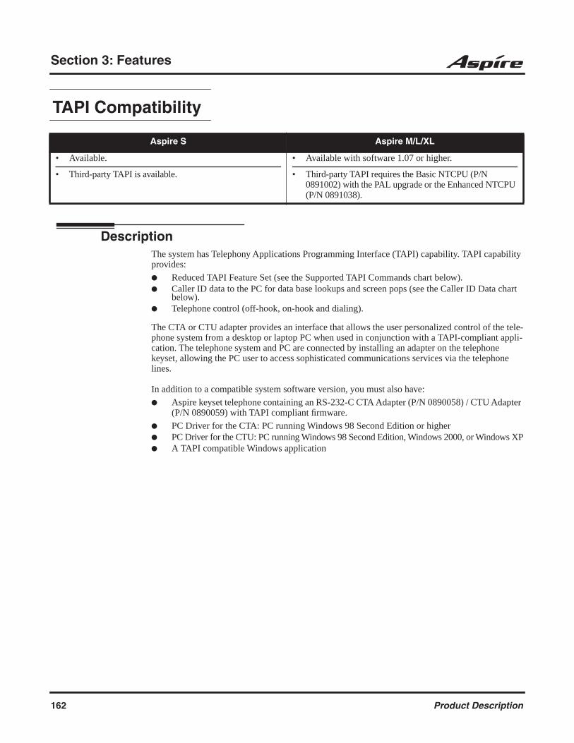
Section 3: Features
TAPI Compatibility
DescriptionThe system has Telephony Applications Programming Interface (TAPI) capability. TAPI capability provides:
Reduced TAPI Feature Set (see the Supported TAPI Commands chart below). Caller ID data to the PC for data base lookups and screen pops (see the Caller ID Data chart
below). Telephone control (off-hook, on-hook and dialing).
The CTA or CTU adapter provides an interface that allows the user personalized control of the tele-phone system from a desktop or laptop PC when used in conjunction with a TAPI-compliant appli-cation. The telephone system and PC are connected by installing an adapter on the telephone keyset, allowing the PC user to access sophisticated communications services via the telephone lines.
In addition to a compatible system software version, you must also have:
Aspire keyset telephone containing an RS-232-C CTA Adapter (P/N 0890058) / CTU Adapter (P/N 0890059) with TAPI compliant firmware.
PC Driver for the CTA: PC running Windows 98 Second Edition or higher PC Driver for the CTU: PC running Windows 98 Second Edition, Windows 2000, or Windows XP A TAPI compatible Windows application
Aspire S Aspire M/L/XL
• Available.
• Third-party TAPI is available.
• Available with software 1.07 or higher.
• Third-party TAPI requires the Basic NTCPU (P/N 0891002) with the PAL upgrade or the Enhanced NTCPU (P/N 0891038).
162 Product Description
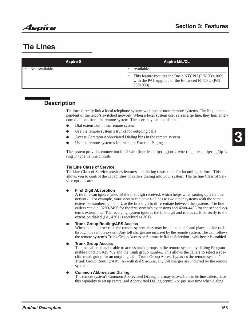
Section 3: Features
3
Tie Lines
DescriptionTie lines directly link a local telephone system with one or more remote systems. The link is inde-pendent of the telco’s switched network. When a local system user seizes a tie line, they hear Inter-com dial tone from the remote system. The user may then be able to:
Dial extensions in the remote system
Use the remote system’s trunks for outgoing calls
Access Common Abbreviated Dialing bins in the remote system
Use the remote system’s Internal and External Paging
The system provides connection for 2-wire (four lead, tip/ring) or 4-wire (eight lead, tip/ring/tip 1/ring 1) type tie line circuits.
Tie Line Class of ServiceTie Line Class of Service provides features and dialing restrictions for incoming tie lines. This allows you to control the capabilities of callers dialing into your system. The tie line Class of Ser-vice options are:
First Digit AbsorptionA tie line can ignore (absorb) the first digit received, which helps when setting up a tie line network. For example, your system can have tie lines to two other systems with the same extension numbering plan. Use the first digit to differentiate between the systems. Tie line callers can dial 3200-3456 for the first system’s extensions and 4200-4456 for the second sys-tem’s extensions. The receiving system ignores the first digit and routes calls correctly to the extension dialed (i.e., 4301 is received as 301).
Trunk Group Routing/ARS AccessWhen a tie line user calls the remote system, they may be able to dial 9 and place outside calls through the remote system. Any toll charges are incurred by the remote system. The call follows the remote system’s Trunk Group Access or Automatic Route Selection - whichever is enabled
Trunk Group AccessTie line callers may be able to access trunk groups in the remote system by dialing Program-mable Function Key *02 and the trunk group number. This allows the callers to select a spe-cific trunk group for an outgoing call. Trunk Group Access bypasses the remote system’s Trunk Group Routing/ARS. As with dial 9 access, any toll charges are incurred by the remote system.
Common Abbreviated DialingThe remote system’s Common Abbreviated Dialing bins may be available to tie line callers. Use this capability to set up centralized Abbreviated Dialing control - or just save time when dialing.
Aspire S Aspire M/L/XL
• Not Available. • Available.
• This feature requires the Basic NTCPU (P/N 0891002) with the PAL upgrade or the Enhanced NTCPU (P/N 0891038).
Product Description 163
Section 3: Features
Operator CallingA tie line caller may be able to dial 0 for the remote system’s operator.
PagingInternal and External Paging may be available to tie line callers. This allows co-workers in adja-cent facilities connected by tie lines, for example, to broadcast announcements to each other.
Direct Trunk AccessThis option allows tie line callers to directly access a trunk for an outside call by dialing #9 and the trunk’s number. Like Trunk Group Access, this bypasses the remote system’s Trunk Group Routing/ARS. Any toll charges are incurred by the remote system.
Forced Trunk DisconnectThe Forced Trunk Disconnect option allows a tie line caller to disconnect (release) another extension’s active outside call. The tie line caller can then place a call on the released trunk. Tie line callers should use Forced Trunk Disconnect only in an emergency, when no other trunks are available.
DISA/Tie Trunk Barge InThe DISA/Tie Trunk Barge In option allows a tie line caller to break into another extension’s established call. This sets up a three-way conversation between the intruding party and the two parties on the initial call.
Tie Line Outgoing Call RestrictionYou can selectively deny incoming tie lines access to your system’s outgoing trunk groups. Incom-ing tie line callers could be able to access your outgoing WATS lines, for example, but not your DDD trunks. The system allows you to set up a restriction matrix for each of your incoming tie lines - for each of your outgoing trunk groups.
Tie Line Toll Restriction ClassIncoming tie lines can have a Toll Restriction Class and be subject to the system’s toll restriction. For example, Toll Restriction can prevent users from dialing 1-900 calls. When an incoming tie line caller tries to use system trunks to dial a 1-900 service, Toll Restriction will deny the call.
Flexible Tie Line Service CompatibilityYou can individually program tie lines for Dial Pulse (DP) or DTMF incoming or outgoing signal-ing. Outgoing tie lines can be either wink start or immediate start.
Wink Start Mode Does Not Require a DTMF ReceiverE&M trunks in wink start mode do not require a DTMF receiver for dial tone detection. It is detected with the wink. This frees the DTMF receivers for other use.
164 Product Description

Section 3: Features
3
Time and Date
DescriptionThe system uses Time and Date for:
Using the Daylight Savings Setup program, you can determine whether the system should automat-ically adjust the system time for daylight savings time/standard time changes.
Clock Adjustment
The system can be programmed to automatically adjust the system clock on a nightly basis. This feature allows you to make adjustments should the system cabinet regularly lose or gain time.
Toll Restriction
Aspire S Aspire M/L/XL
• Available.
• Clock Adjustment program available with software 2.62+.
• Available.
• Clock Adjustment program available with software 2.62+.
• Central Office Calls (Access Maps) • Ring Groups
• Class of Service (Class) • Station Message Detail Recording
• Direct Inward Lines • System Reports
• Display Telephones • Toll Restriction (Class)
• Fax Machine Compatibility • Trunk Group Routing
• Night Service (Automatic) • Voice Response System
• Programmable Trunk Parameters
Aspire S Aspire M/L/XL
• Available- 15 Toll Restriction Classes and 26 extensions.
• Additional programming options available to restrict out-going calls.
• Additional Common Permit Table default entries available.
• Enhanced tie line Toll Restriction requires software 2.65+.
• Available-15 Toll Restriction Classes and 512 extensions.
• Additional programming options added to restrict out-going calls with 1.03+.
• Common Permit Table default entries changed with 1.03+.
• Enhanced tie line Toll Restriction requires software 2.65+.
Product Description 165
Section 3: Features
DescriptionToll Restriction limits the numbers an extension user may dial. By allowing extensions to place only certain types of calls, you can better control long distance costs. The system applies Toll Restriction according to an extension’s Toll Restriction Class. The system allows for up to 15 Toll Restriction Classes.
Toll Restriction offers the following capabilities:
Common Permit Code TableUse the Common Permit Code Table when you have numbers you want all Toll Restriction Classes to dial. To let all users dial 911, for example, put 911 in the Common Permit Code Table. The Common Permit Code Table overrides the Restrict Code and Common Restrict Code Tables. The system provides 10 tables, with 10 entries in each table. Each code is 4 dig-its max., using 0-9, #, * and FLASH (as a wild card).
Common Restrict Code TableThe Common Restrict Code Table lets you globally restrict certain numbers for all Toll Restriction Classes. To prevent all users from dialing directory assistance (411), for example, put 411 in the Common Restrict Code Table. Be sure you don’t allow the codes you want to restrict in the Permit Code Table or the Common Permit Code Table. The system provides 10 tables, with 10 entries in each table. Each code is 4 digits max., using 0-9, #, * and FLASH (as a wild card).
Restrict Code TableWhen you want Toll Restriction to allow most calls and restrict only selected calls, use the Restrict Code Table. To block only 1-900 calls, for example, enter 1900 in the Restrict Code Table. (If the same Toll Restriction Class has both Permit and Restrict Code Tables, the sys-tem restricts calls that you enter only in the Restrict Code Table. Calls entered in both tables are not restricted.) The system provides 4 tables, with 60 entries (restricted codes) in each table. A restricted code is 12 digits maximum, using 0-9, #, * and FLASH (as a wild card).
Permit Code TableThe Permit Code Table lets you set up Toll Restriction so that users can dial only selected (permitted) telephone numbers. Use this table when you want to restrict most calls. To allow all users to dial only area code 203, for example, enter 1203 in the Permit Code Table. 1 + 203 + NNX + nnnn are the only numbers users can dial. (If the same Toll Restriction Class has both Permit and Restrict Code Tables, the system restricts calls that you enter only in the Restrict Code Table. Calls entered in both tables are not restricted.) The system provides 4 tables, with 200 entries (permitted codes) in each table. A permitted code is 12 digits maxi-mum, using 0-9, #, * and FLASH (as a wild card).
International Call RestrictionInternational Call Restriction lets you limit the international calls an extension user may dial. You can build a restrict table to prevent only certain calls, or you can build a permit table to allow only certain calls. To allow most international calls, use the International Call Restrict Table. To prevent most international calls, use the International Call Allow Table. The sys-tem provides 10 International Call Restrict tables with up to 4 digits in each table entry and 20 International Call Allow tables, with up to 6 digits in each table entry. Valid entries are 0-9, #,* and FLASH (for a wild card).
Toll Restriction for Abbreviated DialingAbbreviated Dialing can bypass or follow Toll Restriction. If you allow many users to pro-gram Abbreviated Dialing, consider Toll Restricting the numbers they dial. If only adminis-trators can program Abbreviated Dialing, Toll Restriction may not be necessary. You can separately restrict Group and Common Abbreviated Dialing.
166 Product Description

Section 3: Features
3
Call Digit CountingUse Call Digit Counting to limit the number of digits local callers can dial. You can use this option to prevent users from accessing local dial-up services. For example, set the Maximum Number of Digits in Local Calls to 7 to limit local callers to dialing the exchange code (NNX) and local address (nnnn) only. The system provides 4 tables in which you can make entries for this option. The range is 4-30 digits.
Toll Call Digit Counting With Toll Call Digit Counting, you can limit the number of digits long distance callers can dial. This lets you prevent callers from dialing extensively into long distance dial-up services. You can make four entries (4-30 digits).
Toll Free Trunks Certain trunks can be completely unrestricted, such as the company president’s Private Line. Users can place calls on Toll Free Trunks anytime -- to anywhere, without inadvertently being toll restricted.
PBX Call Restriction Toll Restriction programming lets you enable/disable PBX Call Restriction and enter PBX access codes. You only need to do this if your system is behind a PBX and you have trunks programmed for behind PBX operation. Refer to PBX Compatibility feature for the specifics.
Additional Toll Restriction ProgrammingPrior to 1.03 software, it was possible for users to place a call unrestricted in the following instance:
1. An outside call rings the system, but the caller hangs up before the call is answered.
2. Telco detects the end of the call and returns to an idle status.
3. If a user seizes the trunk within a second or two after this status change, but before the tele-phone stops ringing, the user is able to place an unrestricted call. This is because the system still recognizes the trunk as an incoming call, but to the telco, this is a new outgoing call.
The system only provides Toll Restriction on outgoing calls.
To prevent this from occurring, the system now provides additional programming options. This option is not available for ISDN, DID, or E&M trunks.
Additional Default Entries For Common Permit Code TableAdditional entries have been added to the default Common Permit Code Table. The default setting is now as follows:
Tie Line Toll Restriction EnhancedWith older software, the system only provided the use of Program 34-08 to determine the toll restriction a tie line trunk would follow. This table only allowed 20 entries.
With software 2.65 or higher, a new program is available, 34-01-05 : E&M Tie Line Basic Setup - System Toll Restriction. If this option is set to ’0’, the system will follow the setting in 21-05-13 : Toll Restriction Class - Restriction of Tie Line Calls to determine whether or not the toll restric-tion setting in Program 34-08 is to be followed. If this option is set to ’1’, the system will follow the system toll restriction settings defined in Program 21-05-01 through 21-05-13.
• Table 1: 911 • Table 4: 1822 (new) • Table 7: 1855 (new)
• Table 2: 1800 • Table 5: 1833 (new) • Table 8: 1866 (new)
• Table 3: 1888 • Table 6: 1844 (new) • Table 9: 1877 (new)
Product Description 167
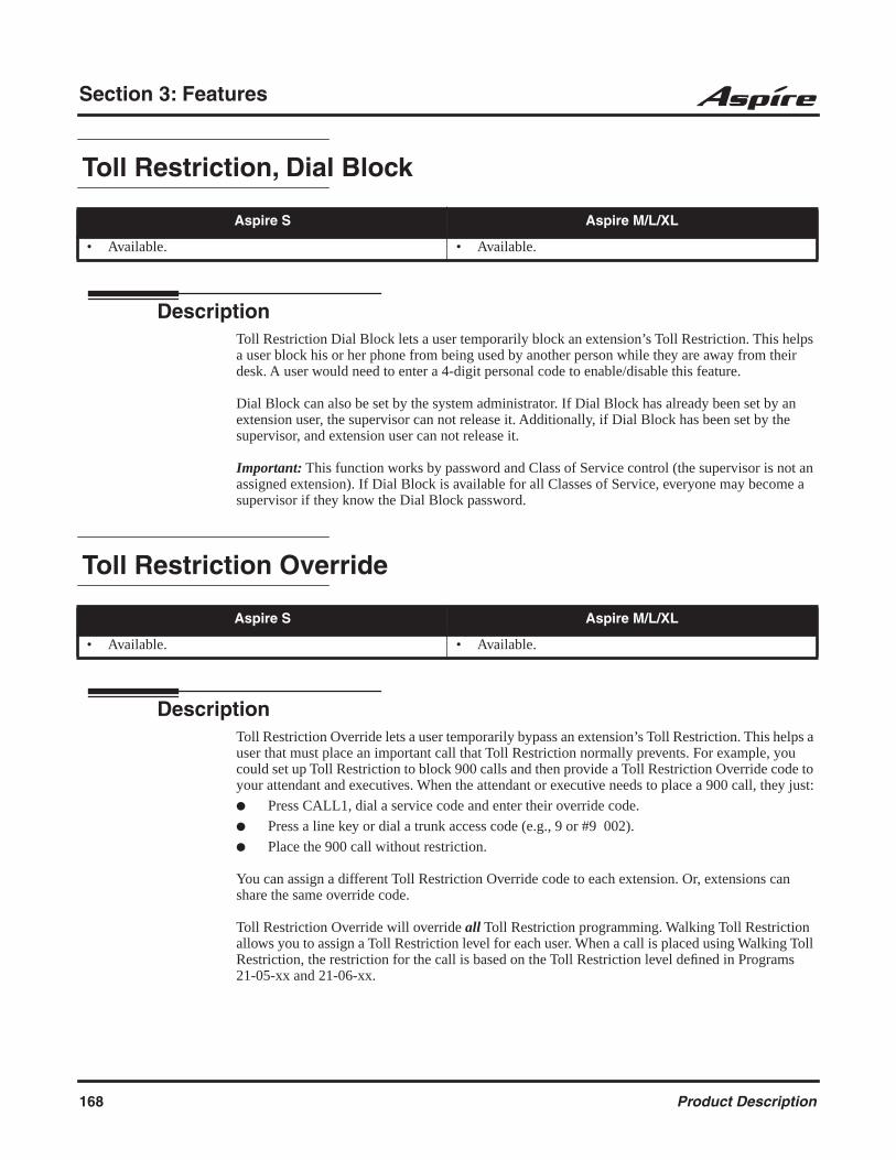
Section 3: Features
Toll Restriction, Dial Block
DescriptionToll Restriction Dial Block lets a user temporarily block an extension’s Toll Restriction. This helps a user block his or her phone from being used by another person while they are away from their desk. A user would need to enter a 4-digit personal code to enable/disable this feature.
Dial Block can also be set by the system administrator. If Dial Block has already been set by an extension user, the supervisor can not release it. Additionally, if Dial Block has been set by the supervisor, and extension user can not release it.
Important: This function works by password and Class of Service control (the supervisor is not an assigned extension). If Dial Block is available for all Classes of Service, everyone may become a supervisor if they know the Dial Block password.
Toll Restriction Override
DescriptionToll Restriction Override lets a user temporarily bypass an extension’s Toll Restriction. This helps a user that must place an important call that Toll Restriction normally prevents. For example, you could set up Toll Restriction to block 900 calls and then provide a Toll Restriction Override code to your attendant and executives. When the attendant or executive needs to place a 900 call, they just:
Press CALL1, dial a service code and enter their override code.
Press a line key or dial a trunk access code (e.g., 9 or #9 002).
Place the 900 call without restriction.
You can assign a different Toll Restriction Override code to each extension. Or, extensions can share the same override code.
Toll Restriction Override will override all Toll Restriction programming. Walking Toll Restriction allows you to assign a Toll Restriction level for each user. When a call is placed using Walking Toll Restriction, the restriction for the call is based on the Toll Restriction level defined in Programs 21-05-xx and 21-06-xx.
Aspire S Aspire M/L/XL
• Available. • Available.
Aspire S Aspire M/L/XL
• Available. • Available.
168 Product Description
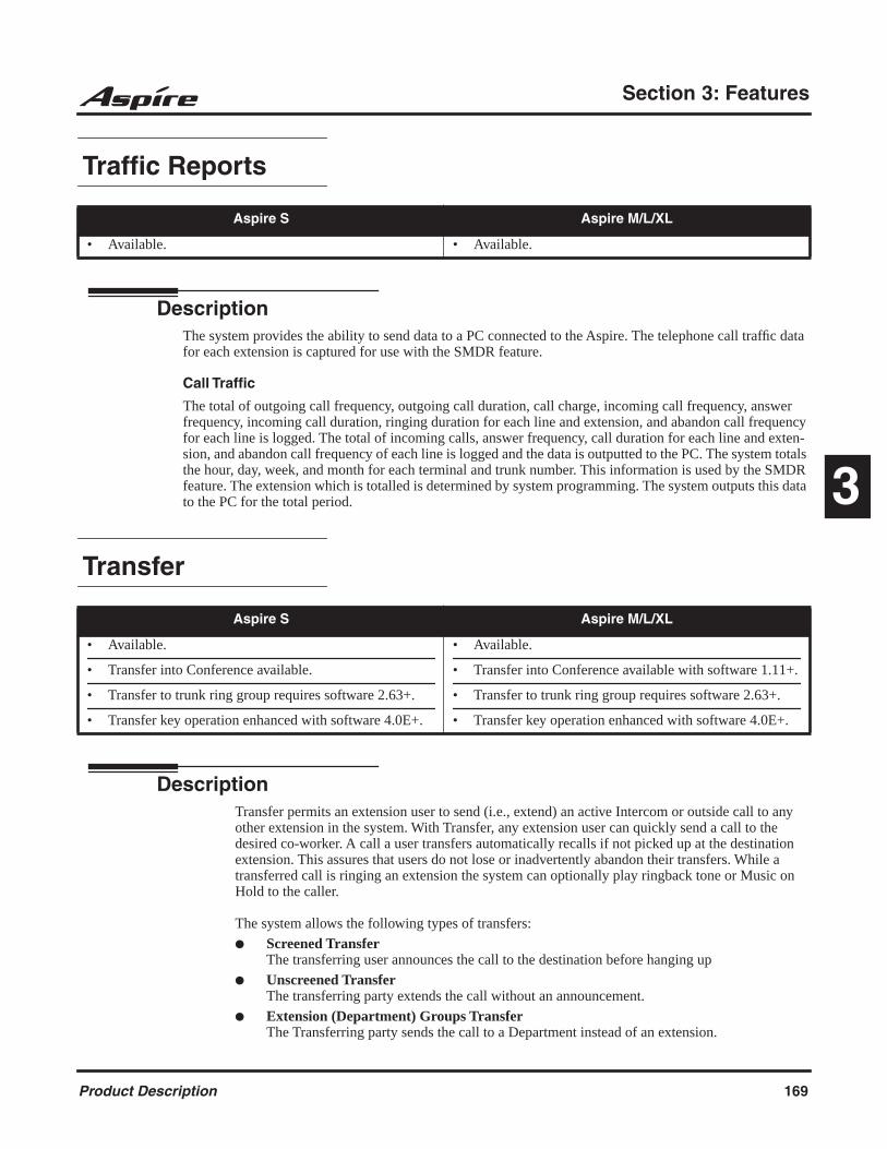
Section 3: Features
3
Traffic Reports
DescriptionThe system provides the ability to send data to a PC connected to the Aspire. The telephone call traffic data for each extension is captured for use with the SMDR feature.
Call Traffic
The total of outgoing call frequency, outgoing call duration, call charge, incoming call frequency, answer frequency, incoming call duration, ringing duration for each line and extension, and abandon call frequency for each line is logged. The total of incoming calls, answer frequency, call duration for each line and exten-sion, and abandon call frequency of each line is logged and the data is outputted to the PC. The system totals the hour, day, week, and month for each terminal and trunk number. This information is used by the SMDR feature. The extension which is totalled is determined by system programming. The system outputs this data to the PC for the total period.
Transfer
DescriptionTransfer permits an extension user to send (i.e., extend) an active Intercom or outside call to any other extension in the system. With Transfer, any extension user can quickly send a call to the desired co-worker. A call a user transfers automatically recalls if not picked up at the destination extension. This assures that users do not lose or inadvertently abandon their transfers. While a transferred call is ringing an extension the system can optionally play ringback tone or Music on Hold to the caller.
The system allows the following types of transfers:
Screened TransferThe transferring user announces the call to the destination before hanging up
Unscreened TransferThe transferring party extends the call without an announcement.
Extension (Department) Groups TransferThe Transferring party sends the call to a Department instead of an extension.
Aspire S Aspire M/L/XL
• Available. • Available.
Aspire S Aspire M/L/XL
• Available.
• Transfer into Conference available.
• Transfer to trunk ring group requires software 2.63+.
• Transfer key operation enhanced with software 4.0E+.
• Available.
• Transfer into Conference available with software 1.11+.
• Transfer to trunk ring group requires software 2.63+.
• Transfer key operation enhanced with software 4.0E+.
Product Description 169
Section 3: Features
Transfer Without HoldingA user presses a busy line key and waits for the call to complete. The system automatically sends them the call when the internal caller hangs up.
Automatic On-Hook Transfer OperationWith Automatic On-Hook Transfer, a Transfer goes through as soon as the transferring user hangs up. For example, extension 304 can answer a trunk, press HOLD, dial 305 and hang up. The system extends the call to extension 305. Without Automatic On-Hook Transfer, the call would stay on Hold at extension 304 when the user hangs up. To extend the call, the user at extension 304 would have to press CONF or a Transfer function key before hanging up.
Each method has advantages. Automatic On-Hook Transfer makes transferring calls easier. However, users have to be more aware of how they handle their calls on Hold. Without Automatic On-Hook Transfer, extending a call becomes a two-step operation - but separate from placing calls on Hold.
Prevent Recall of Transferred CallThe Class of Service program has an option that will allow you to prevent a Transferred call from recalling the originating extension if the call is not answered.
Transfer Call into Conference/Existing CallThis feature allows either a keyset or single line telephone user with Barge In capability the ability to transfer a call into an existing call. This call can be a 2-party call, a Conference call, or a Barge In Conference. The system allows Intercom, analog trunk, ISDN trunk and H.323 trunk calls to be transferred into a Conference call. This would allow, for example, an attendant to locate co-workers and then transfer them into an existing telephone meeting. There is no need for the attendant to locate all the parties at the same time and sequentially add them into the Conference.
This feature is not supported across a network or with S-Bus ports (this includes transferring an S-Bus call into a conference or transferring a call into a conference which includes an S-Bus port).
Transfer to Trunk Ring Group AvailableDepending on your software version, it is possible to transfer a DID or trunk call to the trunk’s defined ring group (defined in Program 22-05-01 : Incoming Trunk Ring Group Assignment). The trunk will then ring the defined extensions for the ring group.
This also allows the transferred call to ring over the External Paging (Program 31-05 : Universal Night Answer/Ring Over Page) so that an employee can answer the call from any available phone.
To enable this feature, the system has a program option, Program 11-15-09 : Service Code Setup Administrative (for Special Access) - Transfer to Trunk Ring Group Code. When a call is trans-ferred using this service code, it's transferred to the ring group destination for that incoming trunk. For example, trunk 2 is in Ring Group 4. When the call is transferred using this service code, the trunk will ring all extensions programmed for Ring Group 4 or ring the External Paging Group for Ring Group 4, depending on how the system is programmed.
Program 22-04-01 : Extension Ring Group Assignment and Program 22-05-01 : Incoming Trunk Ring Group Assignment must be programmed to allow an extension access to the ring groups. If the call is not answered, it can overflow to the destination defined in Program 22-08-01 : DIL/IRG No Answer Destination.
This service code can also be used with the VRS. This provides the caller listening to the VRS mes-sage with the ability to transfer their call and have it ring the external page. The code the caller would dial is defined in Program 25-06-02 : VRS/DISA One-Digit Code Attendant Setup.
170 Product Description

Section 3: Features
3
Transfer Key Operation EnhancedDepending on your software version, pressing the Transfer key while on a call will place the call on hold. With older software, when a Transfer Key was programmed (Program 15-07 or Service Code 851: 06), pressing the Transfer key while on a call did not perform any action.
Trunk Group Routing
DescriptionTrunk Group Routing sets outbound call routing options for users that dial the Trunk Group Rout-ing code (9) for trunk calls. Trunk Group Routing routes calls in the order specified by system pro-gramming. If a user dials 9 and all trunks in the first group are busy, the system may route the call to another group. When you’re setting up your system, Trunk Group Routing will help you mini-mize the expense of toll calls. For example, if your system has outbound WATS lines, OCC lines and DDD lines, use Trunk Group Routing to route calls to the WATS lines first.
Trunk Groups
DescriptionTrunk Groups let you optimize trunk usage for incoming and outgoing calls. With Trunk Groups, users can have loop (rotary) keys for trunk calls. Incoming trunk group calls ring these loop keys. For outgoing calls, the user presses a loop key to access the first available trunk within the group. You set the access order in trunk group programming.
Loop keys give an extension user more available function keys, since the user doesn’t need a sepa-rate line key for each trunk. The user only needs one loop key for each trunk group. This simplifies placing and answering calls.
Aspire S Aspire M/L/XL
• Available - 8 trunk groups and 8 routes. • Available - 100 trunk groups and 100 routes.
Aspire S Aspire M/L/XL
• Available - 8 trunk groups. • Available - 100 trunk groups.
OCCModeratelyExpensive
WATSLeast Expensive
DDDMost Expensive
Third ChoiceSecond ChoiceFirst Choice
Outbound Call
Route 1 Route2 Route 3
Product Description 171

Section 3: Features
Like Trunk Group Routing, Trunk Groups help you minimize the expense of toll calls. For exam-ple, if your system has outbound WATS lines, OCC lines and DDD lines, program the trunk group to route to the WATS lines first.
Trunk Queuing/Camp On
DescriptionTrunk Queuing permits an extension user to queue (wait in line) on hook for a busy trunk or trunk group to become free. The system recalls the queued extension as soon as the trunk is available. The user does not have to manually retry the trunk later. Trunk Queuing lets the caller know when the call can go through. If the extension user does not answer the Trunk Queuing ring, the system cancels the queue request.
With Trunk Camp On, an extension user can queue (wait in line) off hook for a busy trunk or trunk group to become free. The caller connects to the trunk when the trunk becomes free. As with Trunk Queuing, the user does not have to manually retry the trunk later.
Any number of extensions may simultaneously queue or Camp On for the same trunk or trunk group. When a trunk becomes free, the system connects the extensions in the order that the requests were left.
Ultra CallAnalyst
Ultra CallAnalyst is an easy to use, graphically oriented software package that allows you to moni-tor and analyze phone calls, understand phone usage and cut costs. CallAnalyst tracks both incom-ing and outgoing calls accurately as well as the date and time of each call. If you need to track the incoming phone call with name and/or telephone numbers, CallAnalyst requires Caller ID services from the local phone company.
Ultra CallAnalyst increases productivity, facilitates billing and helps detect toll fraud and phone abuse. It also has powerful tabular (text) and graphical report generating capabilities. Reports include extension/line summaries, date/time and department summaries, longest/most expensive calls, most frequently called numbers, and other commonly used summaries. Ultra CallAnalyst also has the ability to automatically generate and Email reports to managers on set schedules. These reports can be used to analyze your telephone as a critical business communication tool, thereby, improving its effectiveness and helping you to reduce your telephone related costs.
Priority Type of Trunk
1 WATS
2 OCC
3 DDD
Aspire S Aspire M/L/XL
• Available. • Available.
172 Product Description

Section 3: Features
3
CallAnalyst keeps track of:
The date and time calls were made or received.
The duration of each call.
Which extension made or received the call.
The CID/ANI, DNIS of the caller.
The trunk or line numbers which handled the call.
Account codes and authorization codes used for the call.
As an example; a report can be generated showing calling patterns by volume or duration on a color coded map of the United States. This can help a Customer Support, Sales Order, or Telemarketing business become more focused, more productive and cost effective.
CallAnalyst Enterprise Server
CallAnalyst Enterprise Server is a network version of Ultra CallAnalyst used for collecting and generating telephone usage reports for multiple telephone systems on a network. It is a scalable call accounting solution for the small to mid-size business.
CallAnalyst Enterprise Server is an easy to use, graphically oriented software package that allows you to monitor and analyze phone calls, understand telephone usage and cut costs. Ultra CallAna-lyst tracks both incoming and outgoing calls accurately.
The application supports connection of heterogenerous (different type) telephone systems as well as the connected interfaces (serial or TCP/IP) and supports real time consolidation and reporting of call accounting data. If you need to track the incoming telephone traffic with calling name and/or telephone numbers, Ultra CallAnalyst requires Caller ID services from the local phone company.
Main Server Minimum PC RequirementsHardware PC with Pentium 4 Processor
512 MB RAM
SVGA Monitor with 1024 x 768 resolution
2 GB of free hard drive space
CD-ROM drive (for software installation)
Available serial port and RS-232 cable (if required)
Network Interface Card (NIC)
Printer (if required to print reports)
Software Windows NT 4.0 (workstation or server) w/SP6, 2000 Professional w/SP3, XP Professional
w/ SP1 or 2003 Server
MS SQL Server 2000 or MSDE (Microsoft Database Engine) for the database (MSDE is included on the application CD)
Microsoft Internet Explorer 5.0 or higher (Internet Explorer is included on the application CD)
Product Description 173
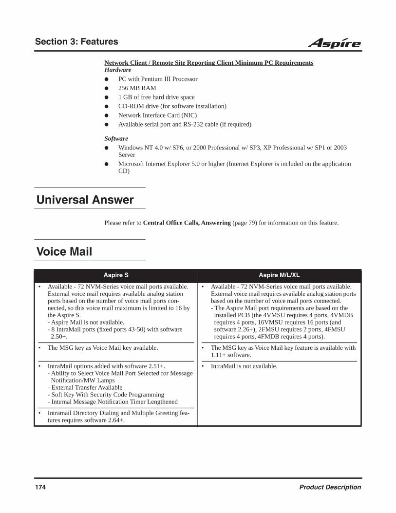
Section 3: Features
Network Client / Remote Site Reporting Client Minimum PC RequirementsHardware PC with Pentium III Processor
256 MB RAM
1 GB of free hard drive space
CD-ROM drive (for software installation)
Network Interface Card (NIC)
Available serial port and RS-232 cable (if required)
Software Windows NT 4.0 w/ SP6, or 2000 Professional w/ SP3, XP Professional w/ SP1 or 2003
Server
Microsoft Internet Explorer 5.0 or higher (Internet Explorer is included on the application CD)
Universal Answer
Please refer to Central Office Calls, Answering (page 79) for information on this feature.
Voice Mail
Aspire S Aspire M/L/XL
• Available - 72 NVM-Series voice mail ports available. External voice mail requires available analog station ports based on the number of voice mail ports con-nected, so this voice mail maximum is limited to 16 by the Aspire S.- Aspire Mail is not available.- 8 IntraMail ports (fixed ports 43-50) with software 2.50+.
• The MSG key as Voice Mail key available.
• IntraMail options added with software 2.51+.- Ability to Select Voice Mail Port Selected for Message Notification/MW Lamps- External Transfer Available- Soft Key With Security Code Programming- Internal Message Notification Timer Lengthened
• Intramail Directory Dialing and Multiple Greeting fea-tures requires software 2.64+.
• Available - 72 NVM-Series voice mail ports available. External voice mail requires available analog station ports based on the number of voice mail ports connected.- The Aspire Mail port requirements are based on the installed PCB (the 4VMSU requires 4 ports, 4VMDB requires 4 ports, 16VMSU requires 16 ports (and software 2.26+), 2FMSU requires 2 ports, 4FMSU requires 4 ports, 4FMDB requires 4 ports).
• The MSG key as Voice Mail key feature is available with 1.11+ software.
• IntraMail is not available.
174 Product Description

Section 3: Features
3
DescriptionThe system is fully compatible with NEC’s analog NVM-Series Voice Mail with Automated Atten-dant Systems. These systems provide telephone users with comprehensive Voice Mail and Auto-mated Attendant features. Voice Mail ends the frustration and cost of missed calls, inaccurate written messages and telephone tag. This frees a company’s busy receptionists and secretaries for more productive work.
Automated Attendant automatically answers the system’s incoming calls. After listening to a cus-tomized message, an outside caller can dial a system extension or use Voice Mail.
Integrated Voice Mail enhances the telephone system with the following features:
Call Forwarding to Voice MailAn extension user can forward their calls to Voice Mail. Once forwarded, calls to the exten-sion connect to that extension’s mailbox. The caller can leave a message in the mailbox instead of calling back later. Forwarding can occur for all calls immediately, for unanswered calls or only when the extension is busy. When a user transfers a call to an extension for-warded to Voice Mail, the call waits for the Delayed Call Forwarding time before routing to the called extension’s mailbox. This gives the transferring party the option of retrieving the call instead of having it go directly to the mailbox.
Leaving a MessageVoice Mail lets a keyset extension user easily leave a message at an extension that is unan-swered, busy or in Do Not Disturb. The caller just presses their Voice Mail key to leave a mes-sage in the called extension’s mailbox. There is no need to call back later.
Transferring to Voice MailBy using Transfer to Voice Mail, a keyset extension user can Transfer a call to the user’s own or a co-worker’s mailbox. After the Transfer goes through, the caller can leave a message in the mailbox.
Conversation RecordWhile on a call, an extension user can have Voice Mail record the conversation. The keyset user just presses the Voice Mail Record key; the ESL user dials a code. Once recorded, the Voice Messaging System stores the conversation as a new message in the user’s mailbox. After calling their mailbox, a user can save, edit or delete the recorded conversation.
Personal Answering Machine EmulationA keyset user can have their idle extension emulate a personal answering machine. This lets Voice Mail screen their calls, just like their answering machine at home. If activated, the exten-sion’s incoming calls route to the user’s subscriber mailbox. Once the mailbox answers, the user hears the caller’s incoming message. The keyset user can then: - Let the call go through to their mailbox- Intercept the call before it goes to their mailbox- Reject the call before it goes to their mailbox
Product Description 175
Section 3: Features
Voice Mail OverflowIf Voice Mail automatically answers trunks, Voice Mail Overflow can reroute those trunks to other extensions when all Voice Mail ports do not answer or, with certain software, are busy. During periods of high traffic, this prevents the outside calls from ringing Voice Mail for an inordinate amount of time. There are two types of Voice Mail Overflow: Immediate and Delayed. With immediate overflow, calls immediately reroute to other extensions when all Voice Mail ports do not answer or, with certain software, are busy. With delayed overflow, calls reroute after a preset interval. Without any type of overflow, the outside calls ring Voice Mail until a port becomes available or the outside caller hangs up.
Message Center MailboxA Message Center Mailbox is a mailbox shared by more than one extension. Any keyset that has a Message Center Key for the shared mailbox can: - Listen to the messages stored in the shared mailbox.- Transfer calls to the shared mailbox.- Use many other Voice Mail features previously available only at an extension’s individual mailbox.
A Message Center Mailbox helps co-workers that work together closely - such as members of the same Department Hunt Group or ACD Group. For example, an ACD Group Supervisor can send important messages to the shared Message Center Mailbox, to which any ACD Group member can respond when time allows. Each ACD Agent’s Message Center Key flashes when messages are waiting. (The Message Center Mailbox can be a mailbox for an installed, uninstalled or virtual extension.)
Voice Mail Caller IDNVM-Series Voice Mail can use ANI/DNIS information to identify the outside caller that left a message in a user’s mailbox. When the message recipient presses TI after hearing a mes-sage, they hear the time the message was sent and the outside telephone number of the mes-sage sender. Refer to ANI/DNIS Compatibility (page 159) for more information on setting up this feature.
Voice Mail QueuingWhen accessing the voice mail, the system provides a voice mail queue. If all the voice mail ports are busy, any calls trying to get to the voice mail will be placed in queue. As the voice mail ports become available, the calls will be connected to the voice mail in the order in which they were received.
As the Voice Mail Queue follows Department Hunting programming, the queue can hold a maxi-mum of 10 calls. If the queue is full or if the voice mail ports are not assigned to a Department Group, the calls will be handled as though there were no voice mail queuing feature enabled. The calls will either access voice mail if a port is available or they will receive a busy signal.
The Voice Mail Queuing feature does not work with the Conversation Record feature.
Park and PageWhen an extension user is away from their phone, the voice mail provides a Park and Page feature which can let them know when they have a call waiting to be answered. To activate Park and Page, the subscriber records the Paging Message. To enable Park and Page, the user records a Paging message. Park and Page will then answer an incoming call and the system broadcasts the prere-corded Paging announcement. When the extension user hears the Page, they can go to any tele-phone and use Directed Call Pickup to intercept the call. Depending on how the subscriber wants Park and Page to operate, they can turn the Paging Message on or off. Refer to the Aspire Mail Sys-tem Guide (P/N 17710SWGxx) for details on setting this feature.
176 Product Description
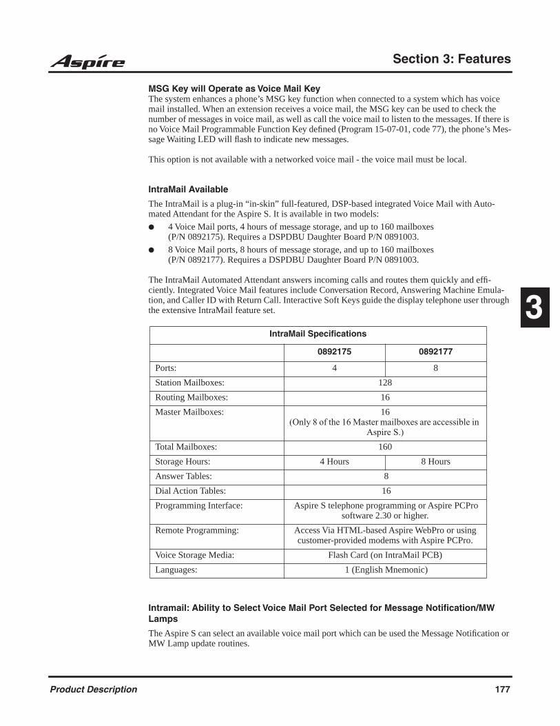
Section 3: Features
3
MSG Key will Operate as Voice Mail KeyThe system enhances a phone’s MSG key function when connected to a system which has voice mail installed. When an extension receives a voice mail, the MSG key can be used to check the number of messages in voice mail, as well as call the voice mail to listen to the messages. If there is no Voice Mail Programmable Function Key defined (Program 15-07-01, code 77), the phone’s Mes-sage Waiting LED will flash to indicate new messages.
This option is not available with a networked voice mail - the voice mail must be local.
IntraMail Available
The IntraMail is a plug-in “in-skin” full-featured, DSP-based integrated Voice Mail with Auto-mated Attendant for the Aspire S. It is available in two models:
4 Voice Mail ports, 4 hours of message storage, and up to 160 mailboxes (P/N 0892175). Requires a DSPDBU Daughter Board P/N 0891003.
8 Voice Mail ports, 8 hours of message storage, and up to 160 mailboxes(P/N 0892177). Requires a DSPDBU Daughter Board P/N 0891003.
The IntraMail Automated Attendant answers incoming calls and routes them quickly and effi-ciently. Integrated Voice Mail features include Conversation Record, Answering Machine Emula-tion, and Caller ID with Return Call. Interactive Soft Keys guide the display telephone user through the extensive IntraMail feature set.
Intramail: Ability to Select Voice Mail Port Selected for Message Notification/MW Lamps
The Aspire S can select an available voice mail port which can be used the Message Notification or MW Lamp update routines.
IntraMail Specifications
0892175 0892177
Ports: 4 8
Station Mailboxes: 128
Routing Mailboxes: 16
Master Mailboxes: 16(Only 8 of the 16 Master mailboxes are accessible in
Aspire S.)
Total Mailboxes: 160
Storage Hours: 4 Hours 8 Hours
Answer Tables: 8
Dial Action Tables: 16
Programming Interface: Aspire S telephone programming or Aspire PCPro software 2.30 or higher.
Remote Programming: Access Via HTML-based Aspire WebPro or using customer-provided modems with Aspire PCPro.
Voice Storage Media: Flash Card (on IntraMail PCB)
Languages: 1 (English Mnemonic)
Product Description 177
Section 3: Features
Intramail: External Transfer Available
The software provides the ability for the IntraMail to perform an external transfer. This allows the IntraMail to route an incoming Automated Attendant call out of the Aspire system on a new trunk based on an Abbreviated Dial number stored in a Dial Action Table.
Intramail: Soft Key With Security Code Programming
The software provides a soft key when programming the security code. This soft key allows a user to select OK/CANCEL following an entry of a new code.
Intramail: Internal Message Notification Timer Lengthened
When Message Notification places a call out, the system will wait up to 30 seconds for ringback, reorder, or busy tone from the trunk. If detected, notification call out processing begins normally. If not detected, the system abandons the call and decrements the Ring No Answer (RNA) count. In older software versions, the system would wait 15 seconds. This could cause notification callbacks to be inadvertently abandoned.
IntraMail: Directory DialingThis feature requires the IntraMail Utility 1.2. The utility and the instruction sheet for
updating the utility are available for downloading from the NEC Technical Support Site (ws1.necii.com). This site requires user registration (contact NEC Sales Support for details).
Directory Dialing allows an Automated Attendant caller to reach an extension by dialing the first few letters in the extension user’s name. With Directory Dialing, the caller does not have to remem-ber the extension number of the person they wish to reach — just their name. Here’s how Directory Dialing works:
1. When the Automated Attendant answers, it sends the call to a Directory Dialing Mailbox. (Optionally, the caller may be asked to dial a digit to access Directory Dialing.)
2. The Directory Dialing Mailbox plays the Directory Dialing Message which asks the caller to dial letters for the name of the person they wish to reach.
3. The caller dials the letters for the person’s name plus #. They can dial by first name or last name, depending on how the Directory Dialing Message was recorded and the Directory Dial-ing Mailbox was set up.
4. IntraMail searches the list of programmed extension names for a match of the caller-entered letters.
5. Voice prompts announce the first three matches, and allow the caller to dial a digit (1-3) to reach one of the announced matches. Additionally, the caller can dial 4 to hear additional matches (if any).
6. The caller dials the digit for the extension they wish to reach, and IntraMail sends the call to that extension. The call is sent as a Screened or Unscreened transfer, depending on program-ming.
For callers to use Directory Dialing, the system must have a name programmed for each extension (up to 15 characters, A-Z, using upper and lower case letters). Each extension should also have a name recorded in their Subscriber Mailbox. In addition, each extension used by Directory Dialing must be installed and must have their Subscriber Mailbox active (Personal or Group).
An outside caller can route to a Master Mailbox or Routing Mailbox programmed as a Directory Dialing Mailbox from:
The Answer Table’s Answer Schedule Override mailbox, Default mailbox, or Routing mail-box.
A GOTO action in the Dial Action Table of a Call Routing Mailbox.
178 Product Description

Section 3: Features
3
IntraMail: Multiple GreetingsThis feature requires the IntraMail Utility 1.2. The utility and the instruction sheet for
updating the utility are available for downloading from the NEC Technical Support Site (ws1.necii.com). This site requires user registration (contact NEC Sales for details).
The mailbox subscriber can record up to three separate greetings and make any one of the three active. When a caller leaves a message in the subscriber’s mailbox, they hear the active greeting. This allows the subscriber, for example, to record separate greetings for work hours, after work, and during vacation. Instead of rerecording their greeting when they leave the office, they can just acti-vate the “after work” greeting instead.
If the active greeting has not been recorded, a caller leaving a message in the subscriber mailbox will hear, “At the tone, you can leave your message for (extension number or name).”
Multiple Greetings requires IntraMail Voice Prompts version 1.2 or higher.
Refer to the Aspire IntraMail System Guide, P/N 0893240, for complete details.
Voice Over
Description
Voice Over lets a user interrupt a keyset extension user busy on another call. With Voice Over, the busy keyset extension user hears an alert tone followed by the voice of the interrupting party. The keyset extension user can respond to the interrupting party without being heard by the original caller. If desired, the keyset extension user can easily switch between their original caller and the interrupting co-worker. The original caller and the interrupting party can never hear each other’s conversation.
Voice Over could help a lawyer, for example, waiting for an urgent call. While on a call with another client, the lawyer’s paralegal could announce the urgent call as soon as it comes in. The lawyer could then give the paralegal instructions how to handle the situation - all without the origi-nal client hearing the conversation.
Either a keyset or 500/2500 set user can initiate a Voice Over, but only a keyset user can receive a Voice Over.
Aspire S Aspire M/L/XL
• Available. • Available.
- Important -Do not use Voice Over to a user on speakerphone as the
conversation may be heard by the outside party.
Product Description 179
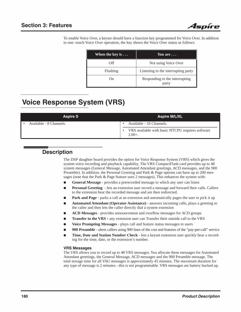
Section 3: Features
To enable Voice Over, a keyset should have a function key programmed for Voice Over. In addition to one- touch Voice Over operation, the key shows the Voice Over status as follows:
Voice Response System (VRS)
DescriptionThe DSP daughter board provides the option for Voice Response System (VRS) which gives the system voice recording and playback capability. The VRS CompactFlash card provides up to 48 system messages (General Message, Automated Attendant greetings, ACD messages, and the 900 Preamble). In addition, the Personal Greeting and Park & Page options can have up to 200 mes-sages (note that the Park & Page feature uses 2 messages). This enhances the system with:
General Message - provides a prerecorded message to which any user can listen
Personal Greeting - lets an extension user record a message and forward their calls. Callers to the extension hear the recorded message and are then redirected.
Park and Page - parks a call at an extension and automatically pages the user to pick it up
Automated Attendant (Operator Assistance) - answers incoming calls, plays a greeting to the caller and then lets the caller directly dial a system extension
ACD Messages - provides announcement and overflow messages for ACD groups
Transfer to the VRS - any extension user can Transfer their outside call to the VRS
Voice Prompting Messages - plays call and feature status messages to users
900 Preamble - alerts callers using 900 lines of the cost and features of the “pay-per-call” service
Time, Date and Station Number Check - lets a keyset extension user quickly hear a record-ing for the time, date, or the extension’s number.
VRS MessagesThe VRS allows you to record up to 48 VRS messages. You allocate these messages for Automated Attendant greetings, the General Message, ACD messages and the 900 Preamble message. The total storage time for all VAU messages is approximately 45 minutes. The maximum duration for any type of message is 2 minutes - this is not programmable. VRS messages are battery backed up.
When the key is . . . You are . . .
Off Not using Voice Over
Flashing Listening to the interrupting party
On Responding to the interrupting party
Aspire S Aspire M/L/XL
• Available - 8 Channels. • Available - 16 Channels.
• VRS available with basic NTCPU requires software 2.00+.
180 Product Description
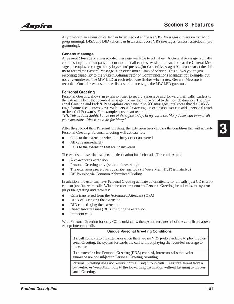
Section 3: Features
3
Any on-premise extension caller can listen, record and erase VRS Messages (unless restricted in programming). DISA and DID callers can listen and record VRS messages (unless restricted in pro-gramming).
General MessageA General Message is a prerecorded message available to all callers. A General Message typically contains important company information that all employees should hear. To hear the General Mes-sage, an employee can go to any keyset and press 4 (for General Message). You can restrict the abil-ity to record the General Message in an extension’s Class of Service. This allows you to give recording capability to the System Administrator or Communications Manager, for example, but not any employee. The MW LED at each telephone flashes when a new General Message is recorded. Once the extension user listens to the message, the MW LED goes out.
Personal GreetingPersonal Greeting allows an extension user to record a message and forward their calls. Callers to the extension hear the recorded message and are then forwarded to the new destination. The Per-sonal Greeting and Park & Page options can have up to 200 messages total (note that the Park & Page feature uses 2 messages). With Personal Greeting, an extension user can add a personal touch to their Call Forwards. For example, a user can record:“Hi. This is John Smith. I’ll be out of the office today. In my absence, Mary Jones can answer all your questions. Please hold on for Mary.”
After they record their Personal Greeting, the extension user chooses the condition that will activate Personal Greeting. Personal Greeting will activate for:
Calls to the extension when it is busy or not answered All calls immediately Calls to the extension that are unanswered
The extension user then selects the destination for their calls. The choices are:
A co-worker’s extension Personal Greeting only (without forwarding) The extension user’s own subscriber mailbox (if Voice Mail (DSP) is installed) Off-Premise via Common Abbreviated Dialing
In addition, the user can have Personal Greeting activate automatically for all calls, just CO (trunk) calls or just Intercom calls. When the user implements Personal Greeting for all calls, the system plays the greeting and reroutes:
Calls transferred from the Automated Attendant (OPA) DISA calls ringing the extension DID calls ringing the extension Direct Inward Lines (DILs) ringing the extension Intercom calls
With Personal Greeting for only CO (trunk) calls, the system reroutes all of the calls listed above except Intercom calls.
Unique Personal Greeting Conditions
If a call comes into the extension when there are no VRS ports available to play the Per-sonal Greeting, the system forwards the call without playing the recorded message to the caller.
If an extension has Personal Greeting (RNA) enabled, Intercom calls that voice announce are not subject to Personal Greeting rerouting.
Personal Greeting does not reroute normal Ring Group calls. Calls transferred from a co-worker or Voice Mail route to the forwarding destination without listening to the Per-sonal Greeting.
Product Description 181

Section 3: Features
Park and PageWhen an extension user is away from their phone, Park and Page can let them know when they have a call waiting to be answered. The Personal Greeting and Park & Page options can have up to 200 messages total (note that the Park & Page feature uses 2 messages). To enable Park and Page, the user records a Personal Greeting along with an additional Paging announcement. Park and Page will then answer an incoming call and play the Personal Greeting to the caller. The caller then lis-tens to Music on Hold (if available) while the system broadcasts the prerecorded Paging announce-ment. When the extension user hears the Page, they can go to any telephone and use Directed Call Pickup to intercept the call.
For example, John Smith could record a Personal Greeting that says:“Hello, this is John Smith. I am away from my phone right now but please hold on while I am auto-matically paged.”
The prerecorded Paging announcement could say: “John Smith, you have a call waiting on your line.”
The incoming caller hears the first message and listens to Music on Hold while the system broad-casts the second message. John Smith could then walk to any phone and pick up his call. If John doesn’t pick up the call, the Page periodically repeats.
Park and Page follows the rules for Personal Greeting for All Calls, immediately rerouted. This means that Park and Page will activate for ringing Intercom calls, DID calls and DISA calls. It will also activate for calls transferred from the Automated Attendant. Additionally, calls from the Auto-mated Attendant follow Automatic Overflow routing if not picked up. Park and Page will activate for transferred outside calls but not play the Personal Greeting to the caller. If a call comes in when the specified Page zone is busy, the system broadcasts the announcement when the zone becomes free.
Automated Attendant (Operator Assistance)Automated Attendant automatically answers outside calls, plays a prerecorded greeting and then lets the outside callers directly dial system extensions, Department Calling Groups and Voice Mail. Automated Attendant provides immediate answering and routing of outside calls without the need for an operator or dispatcher. Automated Attendant provides:
Single Digit DialingSingle Digit Dialing allows Automated Attendant callers to dial extensions, Department Call-ing Groups, and Voice Mail by pressing a single digit. For example, your Automated Atten-dant can greet calls with, “Thank you for calling. To place an order, dial 1. To check on an existing order, dial 2. To speak with an operator, dial 0.” You can set up single digit dialing for each VRS Message programmed to answer outside calls via the Automated Attendant. This allows you to set up day/night/holiday greetings or unique greetings for each incoming trunk. (Keep in mind that, with a default system, if you assign destinations to digits 3, 4 and 5, outside callers will not be able to dial system extensions.)
Simultaneous Call AnsweringWith VRS installed, the Automated Attendant can answer up to 16 calls simultaneously.
Flexible RoutingThe outside caller can directly dial any system extension, Department Calling Group or Voice Mail. If the caller dials a busy extension, Automated Attendant allows them to dial another extension or wait for the busy extension to become free.
182 Product Description

Section 3: Features
3
Automatic OverflowAutomatic Overflow can automatically redirect a call if it can’t go through. This can happen if all VRS ports are busy, if the called extension doesn’t answer, or if the caller misdials or waits too long to dial. (This would occur if the caller is using a dial pulse telephone.) When the call overflows, it rings a designated Ring Group or the Voice Mail system.
Programmable Automated Attendant GreetingsYou can record a different greeting for each trunk answered by the Automated Attendant. The greetings can be different in the day, at night or on holidays or weekends. You can also have a special greeting if the caller misdials. You record the greetings just the way you want. For example, “Dial the three-digit extension number you wish to reach, dial 500 for Sales or dial 600 for Customer Service.” When assigning and recording Automated Attendant greetings, you can choose among the 48 VRS messages.
VRS Waiting MessageUsing VRS Waiting Message, the system can automatically answer an incoming trunk call first (either a normal trunk or one designated for a department group) to let the outside caller hear a recorded message when the call is not answered in a programmed period of time. With this feature, the call keeps ringing at the same destination until it is answered or until other programming, takes affect.
This feature can use up to two messages for an incoming call and the duration between the messages is programmable. These messages will be repeated and, between these messages, either ring back tone or Music on Hold can be played.
This feature has two different modes:
Permanent ModeThis mode sets the feature using system programming and is available for the following types of calls.
A. Normal Incoming CallWhen the call is not answered or a user presses the VRS Waiting Message function key, this feature will be initiated. The waiting message will be played until other no-answer program (transfer to another incoming ring group, disconnect, etc.) takes affect.
B. Designated Call for the Department GroupWhen a department group receives a call from a DID, DIL, DISA or E&M trunk and all terminals in the group are busy, the call will be put in a queue and VRS Waiting Message will be also be initiated. The waiting message will be played until other no-answer pro-gram (transfer to another incoming ring group, disconnect, etc.) takes affect or a terminal becomes available to receive the department call.
Manual ModeThis mode can be programmed by pressing the "VRS Waiting Message" function key from a KST to set this feature for each incoming ring group. This mode can be used for normal incoming calls only.
Transfer to the VRSAny extension user can Transfer their outside call to the VRS. This lets their caller take advantage of the Automated Attendant’s extensive routing capabilities. To Transfer the call, the user simply places the call on Hold, dials the unique VRS service code (set up in system programming) and hangs up.
Product Description 183

Section 3: Features
Voice Prompting MessagesThe VRS feature provides the system with Voice Prompting Messages. These Voice Prompting Messages tell the extension user the status or progress of their call. For example, if a user calls extension 300 when it is busy, they hear, “Station 300 is busy. For Callback, dial 2.”
900 PreambleIf the system has trunks that are part of a 900 (caller paid) service, the VRS can automatically play a prerecorded message when a user answers the call. This prerecorded message should describe the 900 service features and cost. The 900 Preamble ensures that the caller is always aware that they have accessed a 900 “pay- per-call” service. A system user cannot converse with the caller until the preamble message ends. If the caller hangs up before the message completes, they are not charged for the call. If the caller waits for the message to end, they can talk to a system user and call charg-ing begins. The system will answer as many 900 calls as there are available VRS ports. If a 900 calls comes in when all VRS ports are busy, the call will not appear on an extension until a VRS port is available.
You can also use the 900 Preamble message to set up an Auto-Answer with Greeting application. When a receptionist answers a call, the VRS can play a preamble message such as, “Welcome to ABC Company. How can I help you?” When the caller replies, the receptionist answers, “One moment please,” and quickly extends the call to the desired party. This ensures that all incoming calls are answered quickly, courteously and consistently.
Time, Date and Station Number CheckIf the system has a DSP daughter board installed for VRS, any keyset user can find out the time, date or the extension’s number while their phone is idle (on hook). The time and date check saves the user time since they don’t have to look for a clock or calendar. Hearing the extension number conveniently identifies non-display keysets. To find out their extension number, the user presses 6 (for Number). To listen to the time and date, the user presses 8 (for Time).
Available with 64-Port Basic NTCPUPrior to 2.00 software, the VRS feature required the NTCPU to be either:
The Feature Upgrade PAL chip (P/N 0891039) with the 64-Port Basic NTCPU (P/N 0891002)OR
The Enhanced NTCPU (P/N 0891038)
With software 2.00 or higher, and an update of the system’s boot code, the VRS feature is available with the 64-port Basic NTCPU (no Feature Upgrade PAL chip required).
Note that the VRS feature requires a DSPDB be attached to the NTCPU with the optional VRS flash card installed. Although the DSPDB is recognized for this feature, it will not provide any additional tone resources (DTMF receivers, Caller ID receivers, or call progress tone detection).
Refer to the Boot Code Update Instructions, P/N 0893211, for details on installing the updated boot code.
184 Product Description

Section 3: Features
3
VoIP
DescriptionVoIP (voice over Internet protocol or voice over IP) allows the delivery of voice information using the Internet protocol (sending data over the Internet using an IP address). This means that voice information, in a digital form, can be sent in packets over the Internet rather than using the tradi-tional public switch telephone network (CO lines). A major advantage of VoIP and Internet tele-phony is that it avoids the tolls charged by ordinary telephone service.
Using VoIP equipment at a gateway (a network point that acts as an entrance to another network), the packetized voice transmissions from users within the company are received and routed to other parts of the company’s intranet (local area or wide area network) or they can be sent over the Inter-net using CO lines to another gateway.1
The Aspire VoIP supports H.323, H.325, and H.245 trunks and compressions of G.711, G.723.1, and G.729.
The Aspire IP phones are not IEEE 802.3af compliant unless an ILPA adapter is used for PoE. The ILPA, however, cannot be used on the Uniden H.323 telephones. Refer to the ILPA Adapter Instructions, P/N 0893109 for details.
Program Available for Gain Setup of VOIPU PCBThe system software provides an option to adjust the gain setting for a VOIPU PCB.
Calling Party Number Setup for Trunks and ExtensionsThe system provides two programs which allow the programmed entry of the Calling Party Num-ber. These entries determine the information displayed when VoIP trunks and extensions are used.
Aspire S Aspire M/L/XL
• Available - 16 IP extensions max.
• Gain Setup for VOIPU available.
• Enhanced Echo Adjustment available with software 1.18+.
• Calling Party Number available with software 2.09+.
• SIP limited availability with 2.63+ software.
• Out-of-band DTMF signaling requires software 2.63+.
• Available with software 2.00 or higher.64 IP extensions maximum with Basic CPU or with Fea-ture Upgrade PAL chip - 512 IP extensions maximum with enhanced CPU.
• Gain Setup for VOIPU available with software 1.11+.
• Enhanced Echo Adjustment available with software 1.18+.
• Calling Party Number available with software 2.09+.
• SIP limited availability with 2.63+ software.
• Out-of-band DTMF signaling requires software 2.63+.
1. The voice quality of VoIP is dependent on variables such as available bandwidth, network latency and Quality of Service (QoS) initiatives, all of which are controlled by the network and internet service providers. Because these variables are not in NEC’s control, it cannot guarantee the performance of the user’s IP-based remote voice solu-tion. Therefore, NEC recommends connecting VoIP equipment through a local area network using a Private IP address.
Product Description 185

Section 3: Features
Using LANsUsing a LAN setup (local area network) with the Aspire system complies with the ethernet standard (10Base-T/100Base-TX).
To connect a telephone to a LAN connection, the system allows the use of an Aspire digital IP 34-button keyset (referred to as Aspire IPhone), an Aspire digital keyset with an IP Adapter installed or an H.323 IP digital telephone. For details on installing the IP Adapter, refer to the Aspire Hardware Manual (P/N 0893100).
If connecting a LAN to a WAN (wide area network), follow the instructions included with the ADSL modem or gateway device.
Use of SIP Protocol Available (* Limited Feature Release)Contact your NEC Sales Representative for details on the current release status of the
SIP feature.
With this software, the system can now use SIP with the VoIP feature. Session Initiation Protocol (SIP) is a signaling protocol for setting up sessions between one or more clients. The protocol ini-tiates call setup, routing, authentication and other feature messages to endpoints within an IP domain. It is currently the leading signaling protocol for Voice Over IP, gradually replacing H.323.
The Aspire system can now support the following:
IP Trunk : H.323 Trunks / SIP Trunks
IP Extension : D-term IP / H.323 Extensions / SIP ExtensionsSupport for SIP extensions is the same as H.323 telephones.
IP Networking : Networking over H.323These protocol can be used simultaneously.
SIP trunks are used for making a simple IP networking like H.323 IP trunk inter-connection with Program 10-23.
If a common carrier supports SIP, then the Aspire can connect the SIP Carrier and outgoing calls to the PSTN network and the common IP network using an Aspire SIP trunk.
186 Product Description

Section 3: Features
3
Conditions - SIP Trunking Aspire does not support a simultaneous using of a SIP trunk inter-connection and a SIP Trunk
Carrier connection.
Aspire supports a "100rel" option and "Session Timer" option.
Aspire supports "Early Media".
Aspire supports a "DNS resolution access" and a "IP address direct access" for SIP server.
Aspire supports a "MD5" Authentication flow for a SIP server.
Aspire restricts an outgoing call under the following conditions:- SIP configuration failed.- SIP registration failed.- NTCPU/MBU/VOIPU link down.- Lack of VOIPU DSP resource.- Lack of a VoIP bandwidth.
Aspire can connect a SIP server over NAPT router by one static global IP address.
Aspire supports the sub-address feature with SIP trunk inter-connection.
Aspire supports RFC2833 for DTMF relay feature.
Aspire SIP does not support T.38 FAX(H.323 trunk supports T.38 FAX).
Conditions - SIP Extensions SIP extensions support G.711, G.729 CODEC 20ms
Volume Controls
DescriptionEach keyset user can control the volume of incoming ringing, splash tone, Paging, Background Music, Handsfree and your handset. Keysets consolidate all adjustments into the volume buttons. Pressing the VOLUME or VOLUME will adjust the volume level for whichever feature is active (outside call, ICM, ICM ringing, paging, etc.). Pressing these keys when the phone is idle will adjust the contrast level of the telephone’s display. The users should set the volumes for their most comfortable levels.
Handset Volume Reset Option AvailableDepending on your software, an option is available which allows the system to either reset the handset volume back to the default setting after hanging up the handset or it can retain the user’s.
Aspire S Aspire M/L/XL
• Available.
• Handset volume reset option requires software 2.63+.
• Available.
• Handset volume reset option requires software 2.63+.
Product Description 187

Section 3: Features
Warning Tone For Long Conversation
DescriptionThe system can broadcast warning tones to a trunk caller warning them that they have been on the call too long. The tones are just a reminder -- the user may be able to disregard the tones and con-tinue talking if they choose. The outside caller does not hear the warning tones. In addition, warn-ing tones do not occur for Intercom calls and most incoming trunk calls. DISA trunks can also have warning tones. Warning tones are not available to analog single line telephone (SLT) users.
There are two types of warning tones: Alarm Tone 1 and Alarm Tone 2. Alarm Tone 1 is the first set of tones that occur after the user initially places a trunk call. Alarm Tone 2 broadcasts periodi-cally after Alarm Tone 1 as a continued reminder. Each alarm tone consists of three short beeps.
If programmed, DISA calls will be disconnected unless the “continue” code is entered by the user. With the Long Conversation Cutoff feature, incoming or outgoing central office calls can also be disconnected.
Warning Tone for DISA CallersFor DISA callers, with this feature enabled, the warning tone timer begins when an incoming DISA call places an outgoing call and either the inter-digit timer expires or the outgoing call is answered.
With this feature enabled, the warning tone timer begins when an incoming DISA call places an outgoing call and either the inter-digit timer expires or the outgoing call is answered.
If an outside call is transferred to forwarded off-premise using an outside trunk, the warning tone timer begins immediately. This will occur only if either trunk involved in the call is programmed for this feature (Program 14-01-17). When transferring a trunk call off-premise, Program 14-01-13 must be enabled (set to ‘1’).
Aspire S Aspire M/L/XL
• Available. • Available.
FLASH
VOL
CONF
MSG
Volume Down
Handsfree, Handset, Page and BGM Volume
Volume Up
N2IP
-8
188 Product Description
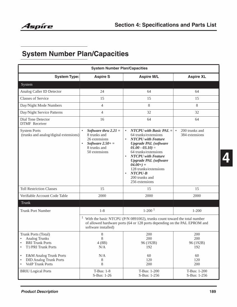
Section 4: Specifications and Parts List
4
Section 4: Specifications and Parts List
System Number Plan/Capacities
System Number Plan/Capacities
System Type: Aspire S Aspire M/L Aspire XL
System
Analog Caller ID Detector 24 64 64
Classes of Service 15 15 15
Day/Night Mode Numbers 4 8 8
Day/Night Service Patterns 4 32 32
Dial Tone DetectorDTMF Receiver
16 64 64
System Ports (trunks and analog/digital extensions)
• Software thru 2.21 = 8 trunks and26 extensions
• Software 2.50+ =8 trunks and50 extensions
• NTCPU with Basic PAL =64 trunks/extensions
• NTCPU with Feature Upgrade PAL (software 01.00 - 03.10) =64 trunks/extensions
• NTCPU with Feature Upgrade PAL (software 04.00+) = 128 trunks/extensions
• NTCPU-B200 trunks and 256 extensions
• 200 trunks and384 extensions
Toll Restriction Classes 15 15 15
Verifiable Account Code Table 2000 2000 2000
Trunk
Trunk Port Number
1-8 1-200 1 1-200
1 With the basic NTCPU (P/N 0891002), trunks count toward the total number of allowed hardware ports (64 or 128 ports depending on the PAL EPROM and software installed)
Trunk Ports (Total)• Analog Trunks• BRI Trunk Ports• T1/PRI Trunk Ports
• E&M Analog Trunk Ports• DID Analog Trunk Ports• VoIP Trunk Ports
88
4 (8B)N/A
N/A88
200200
96 (192B)192
60120200
200200
96 (192B)192
60120200
BRIU Logical Ports T-Bus: 1-8S-Bus: 1-26
T-Bus: 1-200S-Bus: 1-256
T-Bus: 1-200S-Bus: 1-256
Product Description 189

Section 4: Specifications and Parts List
COIU:• Physical Ports• Logical Ports
01-040-8
01-080-200
01-080-200
DIOPU:• Physical Ports• Logical Ports
01-02LD Trunk: 0-8
OPX: 0-8
01-08LD Trunk: 0-200
OPX: 0-25
01-08LD Trunk: 0-200
OPX: 0-25
PRIU Logical Ports N/A T-Bus: 1-200S-Bus: 1-256
T-Bus: 1-200S-Bus: 1-256
TLIU:• Physical Ports• Logical Ports
N/A 01-080-200
01-080-200
VOIPU:• Physical Ports• Logical Ports
1-80-8
01-320-200
01-320-200
DID Translation Tables 20 20 20
DID Translation Table Entries 2000 2000 2000
DISA• Classes of Service• Users
151-15
151-15
151-15
Ring Groups 1-8 1-100 1-100
Tie Line Classes of Service N/A 15 15
Tie Line Toll Restriction Classes N/A 15 15
Trunk Access Maps 1-8 1-200 1-200
Trunk Group Numbers 1-8 1-100 1-100
Trunk Routes 1-8 1-100 1-100
System Number Plan/Capacities
System Type: Aspire S Aspire M/L Aspire XL
190 Product Description
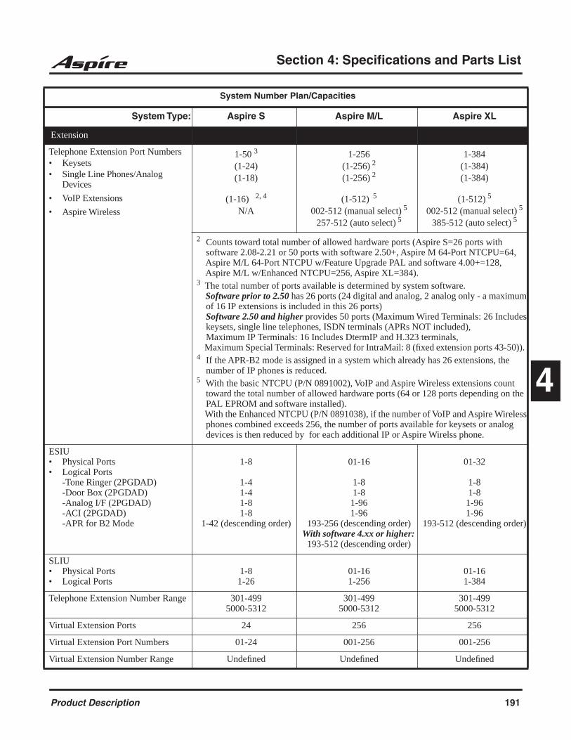
Section 4: Specifications and Parts List
4
Extension
Telephone Extension Port Numbers• Keysets • Single Line Phones/Analog
Devices
• VoIP Extensions
• Aspire Wireless
1-50 3
(1-24)
(1-18)
(1-16) 2, 4
N/A
1-256
(1-256) 2
(1-256) 2
(1-512) 5
002-512 (manual select) 5
257-512 (auto select) 5
1-384
(1-384)
(1-384)
(1-512) 5
002-512 (manual select) 5
385-512 (auto select) 5
2 Counts toward total number of allowed hardware ports (Aspire S=26 ports with software 2.08-2.21 or 50 ports with software 2.50+, Aspire M 64-Port NTCPU=64, Aspire M/L 64-Port NTCPU w/Feature Upgrade PAL and software 4.00+=128, Aspire M/L w/Enhanced NTCPU=256, Aspire XL=384).3 The total number of ports available is determined by system software. Software prior to 2.50 has 26 ports (24 digital and analog, 2 analog only - a maximum of 16 IP extensions is included in this 26 ports) Software 2.50 and higher provides 50 ports (Maximum Wired Terminals: 26 Includes keysets, single line telephones, ISDN terminals (APRs NOT included), Maximum IP Terminals: 16 Includes DtermIP and H.323 terminals, Maximum Special Terminals: Reserved for IntraMail: 8 (fixed extension ports 43-50)). 4 If the APR-B2 mode is assigned in a system which already has 26 extensions, the number of IP phones is reduced.5 With the basic NTCPU (P/N 0891002), VoIP and Aspire Wireless extensions count toward the total number of allowed hardware ports (64 or 128 ports depending on the PAL EPROM and software installed). With the Enhanced NTCPU (P/N 0891038), if the number of VoIP and Aspire Wireless phones combined exceeds 256, the number of ports available for keysets or analog devices is then reduced by for each additional IP or Aspire Wirelss phone.
ESIU• Physical Ports• Logical Ports
-Tone Ringer (2PGDAD)-Door Box (2PGDAD)-Analog I/F (2PGDAD)-ACI (2PGDAD)-APR for B2 Mode
1-8
1-41-41-81-8
1-42 (descending order)
01-16
1-81-81-961-96
193-256 (descending order)With software 4.xx or higher:
193-512 (descending order)
01-32
1-81-81-961-96
193-512 (descending order)
SLIU• Physical Ports• Logical Ports
1-81-26
01-161-256
01-161-384
Telephone Extension Number Range 301-4995000-5312
301-4995000-5312
301-4995000-5312
Virtual Extension Ports 24 256 256
Virtual Extension Port Numbers 01-24 001-256 001-256
Virtual Extension Number Range Undefined Undefined Undefined
System Number Plan/Capacities
System Type: Aspire S Aspire M/L Aspire XL
Product Description 191

Section 4: Specifications and Parts List
2PGDAD Modules 10 56 56
ADA (Recording Jack) Adapters 24 192 192
Aspire Wireless Bases N/A 12 12
Aspire Wireless Phones N/A 120 120
Door Boxes 4 8 8
Door Box Numbers 1-4 1-8 1-8
DSS Consoles Numbers• 24-Button DLS Consoles,
Maximum Installed• 110-Button DSS Consoles,
Maximum Installed
824
4
8256
32
8384
32
Handsfree Adapter (HF-R) 24 192 192
Operator Access Number 0 0 0
Operator Extension 1 1 1
Ringdown Assignments 512 512 512
SLT Adapters 8 16 16
Voice Mail Master Numbers 301-499, 5000-5312 301-499, 5000-5312 301-499, 5000-5312
Abbreviated Dialing
Abbreviated Dialing Groups 8 64 64
Abbreviated Dialing Bins 0-1999 0-1999 0-1999
Abbreviated Dialing Table-Common 1000 1000 1000
ACD
ACD Groups N/A 64 64
ACD Agent Extensions N/A 512 512
ACI
ACI Groups 4 16 16
ACI Ports 8 96 96
Automated Attendant
VRS Message Numbers 1-48 1-48 1-48
Conference
Conference Circuits 32 - maximum(32 Parties Per Conference)
64 - maximum(32 Parties Per Conference)
64 - maximum(32 Parties Per Conference)
System Number Plan/Capacities
System Type: Aspire S Aspire M/L Aspire XL
192 Product Description

Section 4: Specifications and Parts List
4
Data Communication Interfaces
APR Software Port Numbers 193-256With software 4.xx or
higher: 193-512
193-256With software 4.xx or higher:
193-512
193-512
APA Adapters 24 192 192
APR Adapters B1 = 24B2 = 8 prior to 2.50 or 16
with 2.50+
192 192
CTA or CTU Adapters 24 128 128
Module Extension Number Range 301-499, 5000-5312 301-499, 5000-5312 301-499, 5000-5312
Department and Pickup Groups
Department (Extension) Group Numbers
1-8 1-64 1-64
Department (Extension) Group Number Range
301-499, 5000-5312 301-499, 5000-5312 301-499, 5000-5312
Call Pickup Group Numbers 1-8 1-64 1-64
Hotline
Internal Hotline 512 512 512
External Hotline 512 512 512
Paging and Park
Internal Page Group Numbers 0, 1-8 0, 1-9 or 01-64 0, 1-9 or 01-64
External Page Group Numbers 0, 1-8 0, 1-8 0, 1-8
External Speakers• NTCPU• PGDAD Module
8N/A(1-8)
9(1)
(1-8)
9(1)
(1-8)
Park Group Numbers 1-64 1-64 1-64
Park Orbits 1-64 1-64 1-64
SMDR
SMDR Ports 1-2 1-8 1-8
VRS
VRS (on DSP Daughter Board) 1 1 1
VRS Channels 8 16 16
VRS Attendant Messages 3 3 3
VRS Recordable Messages 48 48 48
System Number Plan/Capacities
System Type: Aspire S Aspire M/L Aspire XL
Product Description 193
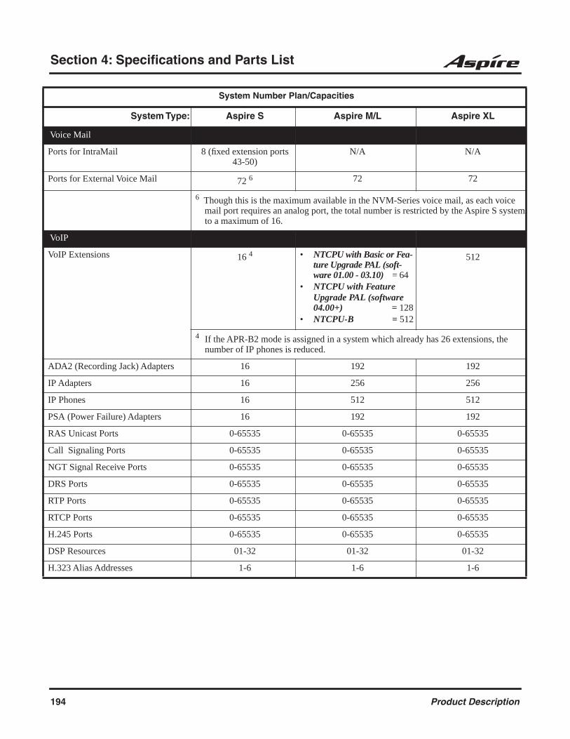
Section 4: Specifications and Parts List
Voice Mail
Ports for IntraMail 8 (fixed extension ports 43-50)
N/A N/A
Ports for External Voice Mail 72 6 72 72
6 Though this is the maximum available in the NVM-Series voice mail, as each voice mail port requires an analog port, the total number is restricted by the Aspire S system to a maximum of 16.
VoIP
VoIP Extensions 16 4 • NTCPU with Basic or Fea-ture Upgrade PAL (soft-ware 01.00 - 03.10) = 64
• NTCPU with Feature Upgrade PAL (software 04.00+) = 128
• NTCPU-B = 512
512
4 If the APR-B2 mode is assigned in a system which already has 26 extensions, the number of IP phones is reduced.
ADA2 (Recording Jack) Adapters 16 192 192
IP Adapters 16 256 256
IP Phones 16 512 512
PSA (Power Failure) Adapters 16 192 192
RAS Unicast Ports 0-65535 0-65535 0-65535
Call Signaling Ports 0-65535 0-65535 0-65535
NGT Signal Receive Ports 0-65535 0-65535 0-65535
DRS Ports 0-65535 0-65535 0-65535
RTP Ports 0-65535 0-65535 0-65535
RTCP Ports 0-65535 0-65535 0-65535
H.245 Ports 0-65535 0-65535 0-65535
DSP Resources 01-32 01-32 01-32
H.323 Alias Addresses 1-6 1-6 1-6
System Number Plan/Capacities
System Type: Aspire S Aspire M/L Aspire XL
194 Product Description
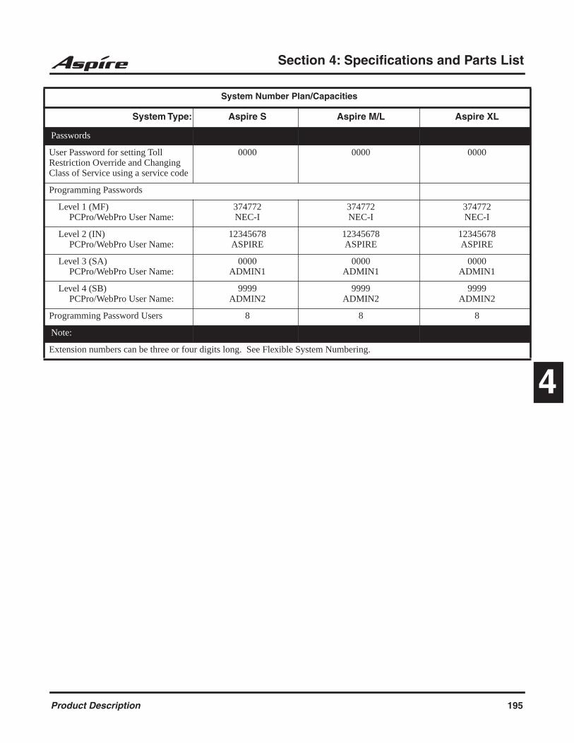
Section 4: Specifications and Parts List
4
Passwords
User Password for setting Toll Restriction Override and Changing Class of Service using a service code
0000 0000 0000
Programming Passwords
Level 1 (MF)PCPro/WebPro User Name:
374772NEC-I
374772NEC-I
374772NEC-I
Level 2 (IN)PCPro/WebPro User Name:
12345678ASPIRE
12345678ASPIRE
12345678ASPIRE
Level 3 (SA)PCPro/WebPro User Name:
0000ADMIN1
0000ADMIN1
0000ADMIN1
Level 4 (SB)PCPro/WebPro User Name:
9999ADMIN2
9999ADMIN2
9999ADMIN2
Programming Password Users 8 8 8
Note:
Extension numbers can be three or four digits long. See Flexible System Numbering.
System Number Plan/Capacities
System Type: Aspire S Aspire M/L Aspire XL
Product Description 195
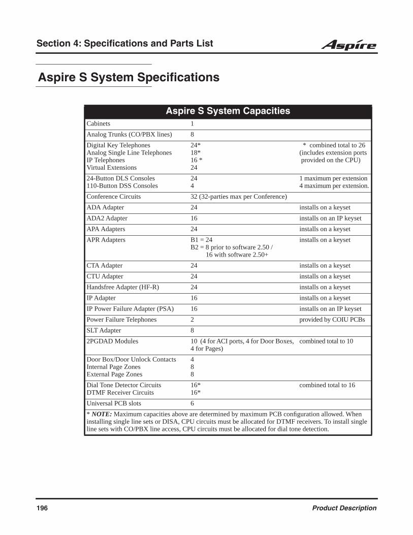
Section 4: Specifications and Parts List
Aspire S System Specifications
Aspire S System CapacitiesCabinets 1
Analog Trunks (CO/PBX lines) 8
Digital Key TelephonesAnalog Single Line TelephonesIP TelephonesVirtual Extensions
24*18*16 *24
* combined total to 26 (includes extension ports provided on the CPU)
24-Button DLS Consoles110-Button DSS Consoles
244
1 maximum per extension4 maximum per extension.
Conference Circuits 32 (32-parties max per Conference)
ADA Adapter 24 installs on a keyset
ADA2 Adapter 16 installs on an IP keyset
APA Adapters 24 installs on a keyset
APR Adapters B1 = 24B2 = 8 prior to software 2.50 / 16 with software 2.50+
installs on a keyset
CTA Adapter 24 installs on a keyset
CTU Adapter 24 installs on a keyset
Handsfree Adapter (HF-R) 24 installs on a keyset
IP Adapter 16 installs on a keyset
IP Power Failure Adapter (PSA) 16 installs on an IP keyset
Power Failure Telephones 2 provided by COIU PCBs
SLT Adapter 8
2PGDAD Modules 10 (4 for ACI ports, 4 for Door Boxes, 4 for Pages)
combined total to 10
Door Box/Door Unlock ContactsInternal Page ZonesExternal Page Zones
488
Dial Tone Detector CircuitsDTMF Receiver Circuits
16*16*
combined total to 16
Universal PCB slots 6
* NOTE: Maximum capacities above are determined by maximum PCB configuration allowed. When installing single line sets or DISA, CPU circuits must be allocated for DTMF receivers. To install single line sets with CO/PBX line access, CPU circuits must be allocated for dial tone detection.
196 Product Description

Section 4: Specifications and Parts List
4
Aspire S PCB CapacitiesCPU Central Processing Unit 1
ENTU LAN CTI 1
8ESIU 8 Digital Stations 2
4SLIU 4 Analog Stations 4
4SLIDB 4 Analog Stations Daughter Board (installs on 4SLIU)
0 - If 4 4SLIU PCBs installed1 - If 3 4SLIU PCBs installed2 - If 2 4SLIU PCBs installed
4COIU 4 Analog/Loop Start Trunks (no ground start) 2
2DIOPU 2 DID/OPX Trunks 4
4VOIPU 4 VoIP Media Gateway 3
4VOIPDB 4 VoIP Media Gateway Daughter Board (installs on 4VOIPU)
3
Product Description 197
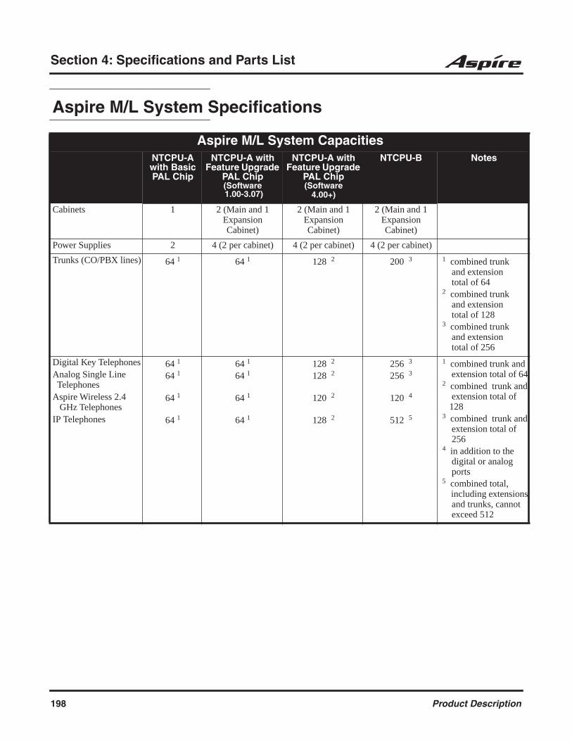
Section 4: Specifications and Parts List
Aspire M/L System Specifications
Aspire M/L System CapacitiesNTCPU-A with Basic PAL Chip
NTCPU-A with Feature Upgrade
PAL Chip(Software 1.00-3.07)
NTCPU-A with Feature Upgrade
PAL Chip(Software
4.00+)
NTCPU-B Notes
Cabinets 1 2 (Main and 1 Expansion Cabinet)
2 (Main and 1 Expansion Cabinet)
2 (Main and 1 Expansion Cabinet)
Power Supplies 2 4 (2 per cabinet) 4 (2 per cabinet) 4 (2 per cabinet)
Trunks (CO/PBX lines) 64 1 64 1 128 2 200 3 1 combined trunk and extension total of 64 2 combined trunk and extension total of 128 3 combined trunk and extension total of 256
Digital Key TelephonesAnalog Single Line TelephonesAspire Wireless 2.4 GHz TelephonesIP Telephones
64 1 64 1
64 1
64 1
64 1
64 1
64 1
64 1
128 2
128 2
120 2
128 2
256 3
256 3
120 4
512 5
1 combined trunk and extension total of 64 2 combined trunk and extension total of 128 3 combined trunk and extension total of 256 4 in addition to the digital or analog ports 5 combined total, including extensions and trunks, cannot exceed 512
198 Product Description
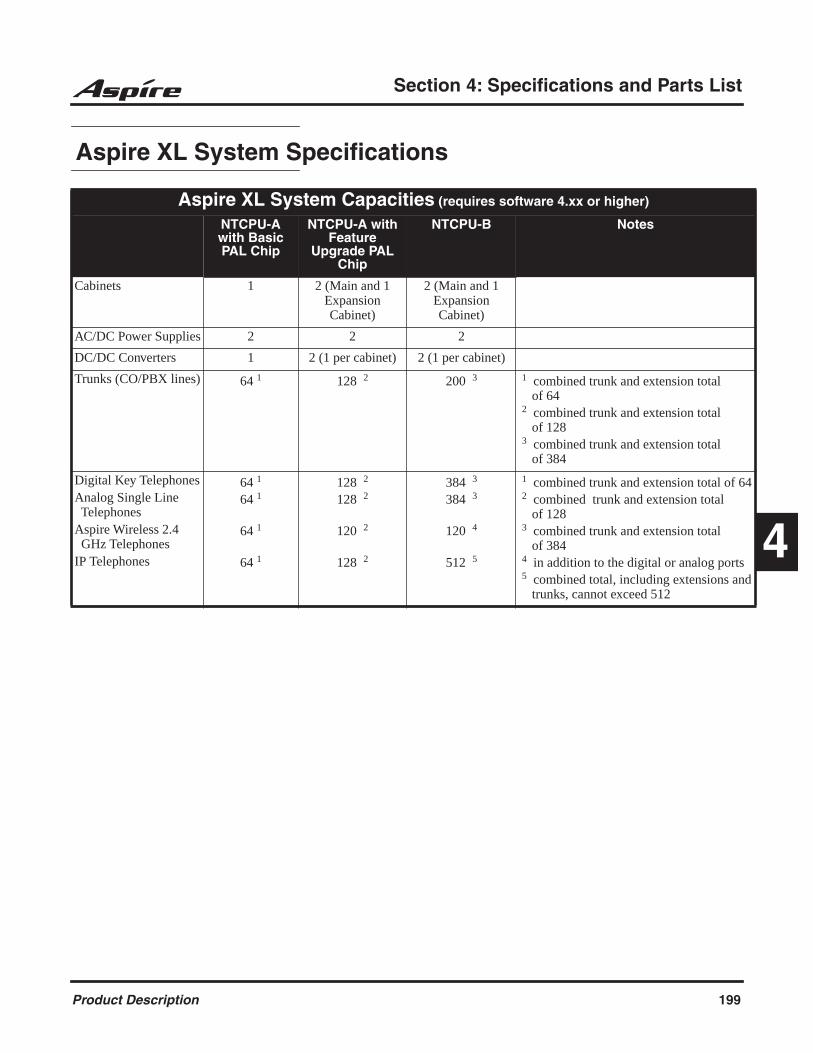
Section 4: Specifications and Parts List
4
Aspire XL System Specifications
Aspire XL System Capacities (requires software 4.xx or higher)
NTCPU-A with Basic PAL Chip
NTCPU-A with Feature
Upgrade PAL Chip
NTCPU-B Notes
Cabinets 1 2 (Main and 1 Expansion Cabinet)
2 (Main and 1 Expansion Cabinet)
AC/DC Power Supplies 2 2 2
DC/DC Converters 1 2 (1 per cabinet) 2 (1 per cabinet)
Trunks (CO/PBX lines) 64 1 128 2 200 3 1 combined trunk and extension total of 64 2 combined trunk and extension total of 128 3 combined trunk and extension total of 384
Digital Key TelephonesAnalog Single Line TelephonesAspire Wireless 2.4 GHz TelephonesIP Telephones
64 1 64 1
64 1
64 1
128 2
128 2
120 2
128 2
384 3
384 3
120 4
512 5
1 combined trunk and extension total of 64 2 combined trunk and extension total of 128 3 combined trunk and extension total of 384 4 in addition to the digital or analog ports 5 combined total, including extensions and trunks, cannot exceed 512
Product Description 199
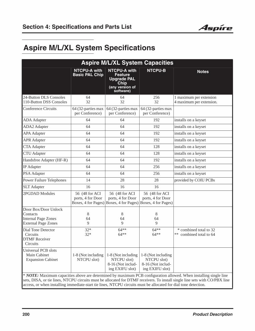
Section 4: Specifications and Parts List
Aspire M/L/XL System Specifications
Aspire M/L/XL System CapacitiesNTCPU-A with
Basic PAL ChipNTCPU-A with
Feature Upgrade PAL
Chip(any version of
software)
NTCPU-B Notes
24-Button DLS Consoles110-Button DSS Consoles
6432
6432
25632
1 maximum per extension4 maximum per extension.
Conference Circuits 64 (32-parties max per Conference)
64 (32-parties max per Conference)
64 (32-parties max per Conference)
ADA Adapter 64 64 192 installs on a keyset
ADA2 Adapter 64 64 192 installs on a keyset
APA Adapter 64 64 192 installs on a keyset
APR Adapter 64 64 192 installs on a keyset
CTA Adapter 64 64 128 installs on a keyset
CTU Adapter 64 64 128 installs on a keyset
Handsfree Adapter (HF-R) 64 64 192 installs on a keyset
IP Adapter 64 64 256 installs on a keyset
PSA Adapter 64 64 256 installs on a keyset
Power Failure Telephones 14 28 28 provided by COIU PCBs
SLT Adapter 16 16 16
2PGDAD Modules 56 (48 for ACI ports, 4 for Door
Boxes, 4 for Pages)
56 (48 for ACI ports, 4 for Door
Boxes, 4 for Pages)
56 (48 for ACI ports, 4 for Door
Boxes, 4 for Pages)
Door Box/Door Unlock ContactsInternal Page ZonesExternal Page Zones
8649
8649
8649
Dial Tone Detector CircuitsDTMF Receiver Circuits
32*32*
64**64**
64**64**
* combined total to 32** combined total to 64
Universal PCB slots Main Cabinet Expansion Cabinet
1-8 (Not including NTCPU slot)
1-8 (Not including NTCPU slot)
8-16 (Not includ-ing EXIFU slot)
1-8 (Not including NTCPU slot)
8-16 (Not includ-ing EXIFU slot)
* NOTE: Maximum capacities above are determined by maximum PCB configuration allowed. When installing single line sets, DISA, or tie lines, NTCPU circuits must be allocated for DTMF receivers. To install single line sets with CO/PBX line access, or when installing immediate-start tie lines, NTCPU circuits must be allocated for dial tone detection.
200 Product Description
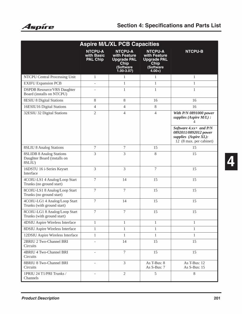
Section 4: Specifications and Parts List
4
Aspire M/L/XL PCB CapacitiesNTCPU-A with Basic PAL Chip
NTCPU-A with Feature Upgrade PAL
Chip(Software 1.00-3.07)
NTCPU-A with Feature Upgrade PAL
Chip(Software
4.00+)
NTCPU-B
NTCPU Central Processing Unit 1 1 1 1
EXIFU Expansion PCB - 1 1 1
DSPDB Resource/VRS Daughter Board (installs on NTCPU)
- 1 1 1
8ESIU 8 Digital Stations 8 8 16 16
16ESIU16 Digital Stations 4 4 8 16
32ESIU 32 Digital Stations 2 4 4 With P/N 0891000 power supplies (Aspire M/L) :
4
Software 4.xx+ and P/N 0892011/0892012 power supplies (Aspire XL):
12 (8 max. per cabinet)
8SLIU 8 Analog Stations 7 7 15 15
8SLIDB 8 Analog Stations Daughter Board (installs on 8SLIU)
3 3 8 15
16DSTU 16 i-Series Keyset Interface
3 3 7 15
4COIU-LS1 4 Analog/Loop Start Trunks (no ground start)
7 14 15 15
8COIU-LS1 8 Analog/Loop Start Trunks (no ground start)
7 7 15 15
4COIU-LG1 4 Analog/Loop Start Trunks (with ground start)
7 14 15 15
8COIU-LG1 8 Analog/Loop Start Trunks (with ground start)
7 7 15 15
4DSIU Aspire Wireless Interface 1 1 1 1
8DSIU Aspire Wireless Interface 1 1 1 1
12DSIU Aspire Wireless Interface 1 1 1 1
2BRIU 2 Two-Channel BRI Circuits
- 14 15 15
4BRIU 4 Two-Channel BRI Circuits
- 7 15 15
8BRIU 8 Two-Channel BRI Circuits
- 3 As T-Bus: 8As S-Bus: 7
As T-Bus: 12As S-Bus: 15
1PRIU 24 T1/PRI Trunks / Channels
- 2 5 8
Product Description 201
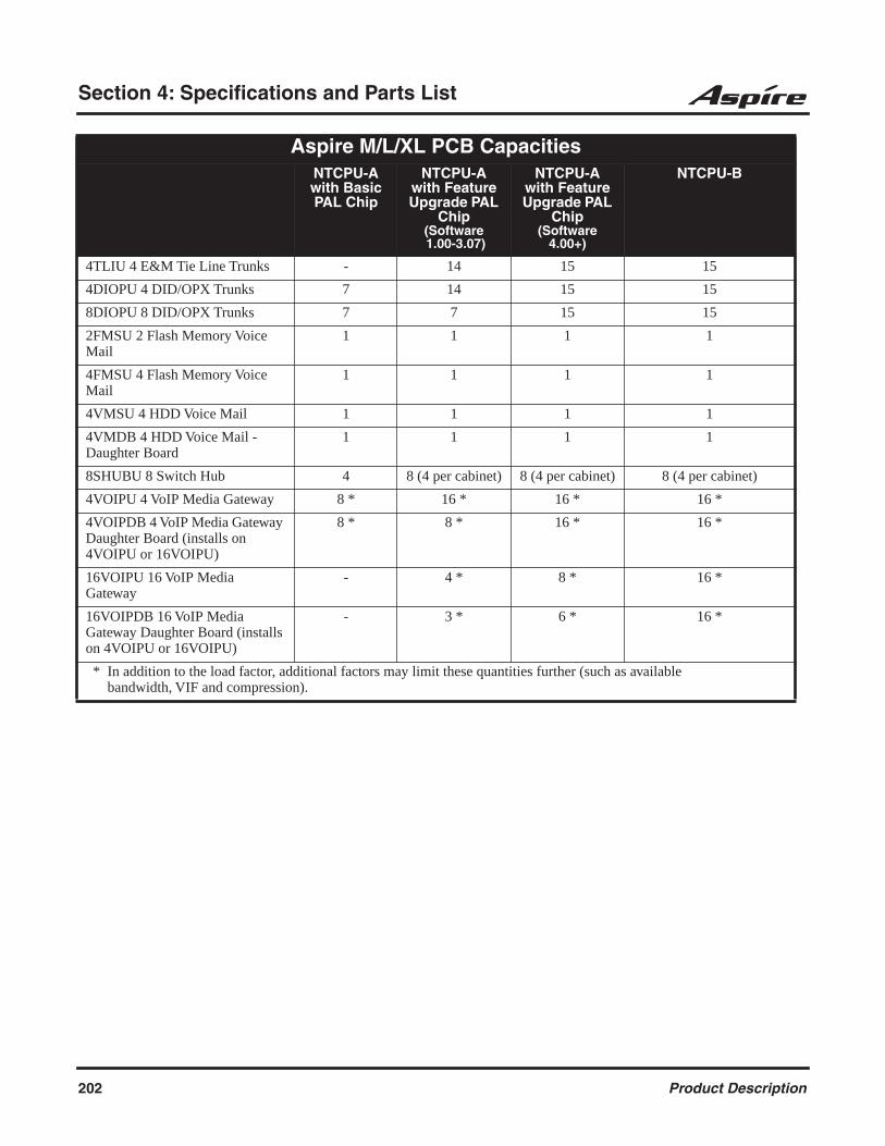
Section 4: Specifications and Parts List
4TLIU 4 E&M Tie Line Trunks - 14 15 15
4DIOPU 4 DID/OPX Trunks 7 14 15 15
8DIOPU 8 DID/OPX Trunks 7 7 15 15
2FMSU 2 Flash Memory Voice Mail
1 1 1 1
4FMSU 4 Flash Memory Voice Mail
1 1 1 1
4VMSU 4 HDD Voice Mail 1 1 1 1
4VMDB 4 HDD Voice Mail - Daughter Board
1 1 1 1
8SHUBU 8 Switch Hub 4 8 (4 per cabinet) 8 (4 per cabinet) 8 (4 per cabinet)
4VOIPU 4 VoIP Media Gateway 8 * 16 * 16 * 16 *
4VOIPDB 4 VoIP Media Gateway Daughter Board (installs on 4VOIPU or 16VOIPU)
8 * 8 * 16 * 16 *
16VOIPU 16 VoIP Media Gateway
- 4 * 8 * 16 *
16VOIPDB 16 VoIP Media Gateway Daughter Board (installs on 4VOIPU or 16VOIPU)
- 3 * 6 * 16 *
* In addition to the load factor, additional factors may limit these quantities further (such as available bandwidth, VIF and compression).
Aspire M/L/XL PCB CapacitiesNTCPU-A with Basic PAL Chip
NTCPU-A with Feature Upgrade PAL
Chip(Software 1.00-3.07)
NTCPU-A with Feature Upgrade PAL
Chip(Software
4.00+)
NTCPU-B
202 Product Description

Section 4: Specifications and Parts List
4
Environmental RequirementsMeeting established environmental standards maximizes the life of the system. Refer to the Standard Practices Manual for further information. Be sure that the site is not:1. In direct sunlight or in hot, cold or humid places.2. In dusty areas or in areas where sulfuric gases are produced.3. In places where shocks or vibrations are frequent or strong.4. In places where water or other fluids comes in contact with the main equipment.5. In areas near high-frequency machines or electric welders.6. Near computers, telexes, microwaves, air conditioners, etc.7. Near radio antennas (including shortwave).
Environmental SpecificationsCabinets, PCBs and Key Telephones
Temperature: 0oC - 40oC (32 - 104oF)Humidity: 10-90% RH
Door BoxTemperature: -20oC - 60oC (-4 - 140oF)Humidity: 20-80% (non-condensing)
Aspire S Power SupplyOperating:Temperature: 0oC - 60oC (32 - 140oF)Humidity: 10-90% RHStorage:Temperature: -20oC - 75oC (-4 - 167oF)Humidity: 10-95% RH
Aspire Power SupplyOperating:Temperature: 0oC - 40oC (32 - 104oF)Humidity: 20-90% RHStorage:Temperature: -40oC - 75oC (-4 - 167oF)Humidity: 10-95% RH
VMSU-A1 PCBTemperature: +5oC - 40oC (41-104oF)Humidity: 10-90% RH
Power RequirementsA dedicated 110 VAC 60 Hz circuit located within seven feet of the cabinet is required. You should install a separate dedicated outlet for each cabinet.
CautionDouble Pole/Neutral Fusing
(power supply fuses located at both the L and N side)
Site RequirementsThe system can be floor-, wall- or rack-mounted. Brackets secure each cabinet to a wall.
Product Description 203
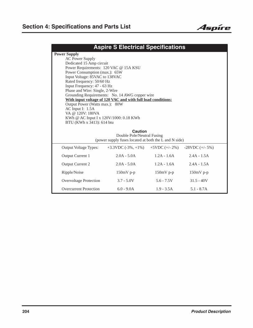
Section 4: Specifications and Parts List
Aspire S Electrical SpecificationsPower Supply
AC Power SupplyDedicated 15 Amp circuitPower Requirements: 120 VAC @ 15A KSUPower Consumption (max.): 65WInput Voltage: 85VAC to 138VACRated frequency: 50/60 HzInput Frequency: 47 - 63 HzPhase and Wire: Single, 2-WireGrounding Requirements: No. 14 AWG copper wireWith input voltage of 120 VAC and with full load conditions:Output Power (Watts max.): 80WAC Input I: 1.5AVA @ 120V: 180VAKWh @ AC Input I x 120V/1000: 0.18 KWhBTU (KWh x 3413): 614 btu
CautionDouble Pole/Neutral Fusing
(power supply fuses located at both the L and N side)
Output Voltage Types: +3.3VDC (-3%, +1%) +5VDC (+/- 2%) -28VDC (+/- 5%)
Output Current 1 2.0A - 5.0A 1.2A - 1.6A 2.4A - 1.5A
Output Current 2 2.0A - 5.0A 1.2A - 1.6A 2.4A - 1.5A
Ripple/Noise 150mV p-p 150mV p-p 150mV p-p
Overvoltage Protection 3.7 - 5.0V 5.6 - 7.5V 31.5 - 40V
Overcurrent Protection 6.0 - 9.0A 1.9 - 3.5A 5.1 - 8.7A
204 Product Description

Section 4: Specifications and Parts List
4
Aspire M/L Electrical SpecificationsPower Supply
AC Power SupplyDedicated 15 Amp circuitPower Requirements: 120 VAC @ 15A Main CabinetPower Consumption: Base Cabinet=360W (493 VA), Expansion Cabinet=360W (493 VA), total
720W (986 VA)Input Voltage: 85VAC to 135VACFrequency: 47 Hz - 63Hz (Rated frequency: 50/60 Hz)Phase and Wire: Single, 2-WireGrounding Requirements: No. 14 AWG copper wireWith input voltage of 120 VAC and with full load conditions:Output Power: One Power Supply: Base Cabinet=100.5W
Two Power Supplies: Base Cabinet=200.9W, Expansion Cabinet=200.9, total 401.8W
AC Input I: One Power Supply: Base Cabinet=2.06ATwo Power Supplies: Base Cabinet=4.11A, Expansion Cabinet=4.11A, total 8.22A
VA @ 120V: One Power Supply: Base Cabinet=246.6VATwo Power Supplies: Base Cabinet=493.2 VA, Expansion Cabinet=493.2 VA, total 986.4 VA
KWh @ AC Input I x 120V/1000: One Power Supply: Base Cabinet=0.247 KWhTwo Power Supplies: Base Cabinet=0.493 KWh, Expansion Cabinet=0.493 KWh,total 0.986 KWh
BTU (KWh x 3413): One Power Supply: Base Cabinet=842 btuTwo Power Supplies: Base Cabinet=1683 btu, Expansion Cabinet=1683 btu, total 3366 btu
CautionDouble Pole/Neutral Fusing
(power supply fuses located at both the L and N side)
Output Voltage Types +3.42VDC (-3%, +1%) +5VDC (+/- 2%) -48VDC (+/- 5%)
Output Current 1 0.0A - 6.0A 0.0A - 5.0A 0.0A - 1.0A
Output Current 2 0.0A - 3.2A 0.0A - 1.0A 0.0A - 2.0A
Ripple/Noise 50mV p-p 100mV p-p 200mV p-p
Overvoltage Protection 3.7 - 8.0V 5.6 - 13.0V -55.0 - 64.8V
Overcurrent Protection 6.6 - 7.7A 5.5 - 6.5A 2.2 - 2.6A
Product Description 205
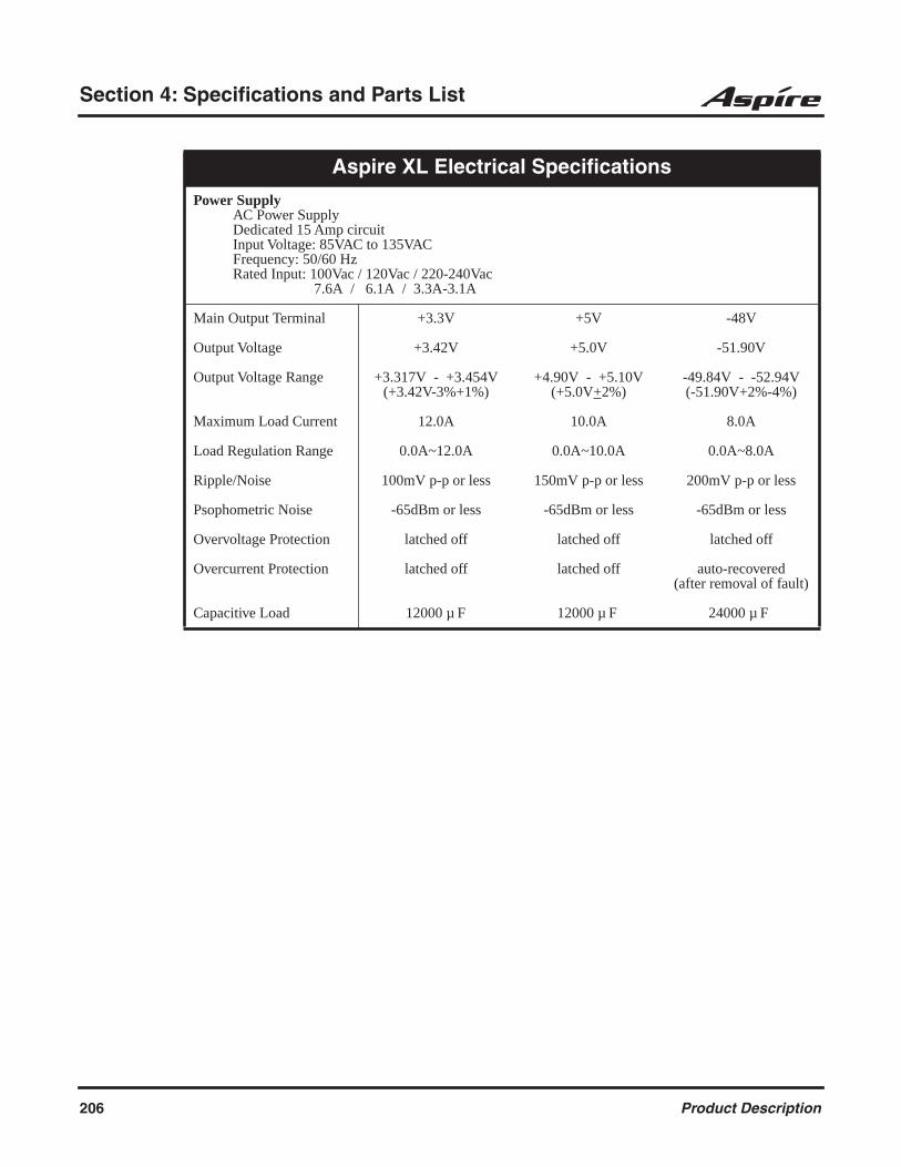
Section 4: Specifications and Parts List
Aspire XL Electrical Specifications
Power SupplyAC Power SupplyDedicated 15 Amp circuitInput Voltage: 85VAC to 135VACFrequency: 50/60 HzRated Input: 100Vac / 120Vac / 220-240Vac 7.6A / 6.1A / 3.3A-3.1A
Main Output Terminal +3.3V +5V -48V
Output Voltage +3.42V +5.0V -51.90V
Output Voltage Range +3.317V - +3.454V(+3.42V-3%+1%)
+4.90V - +5.10V(+5.0V+2%)
-49.84V - -52.94V(-51.90V+2%-4%)
Maximum Load Current 12.0A 10.0A 8.0A
Load Regulation Range 0.0A~12.0A 0.0A~10.0A 0.0A~8.0A
Ripple/Noise 100mV p-p or less 150mV p-p or less 200mV p-p or less
Psophometric Noise -65dBm or less -65dBm or less -65dBm or less
Overvoltage Protection latched off latched off latched off
Overcurrent Protection latched off latched off auto-recovered(after removal of fault)
Capacitive Load 12000 µ F 12000 µ F 24000 µ F
206 Product Description
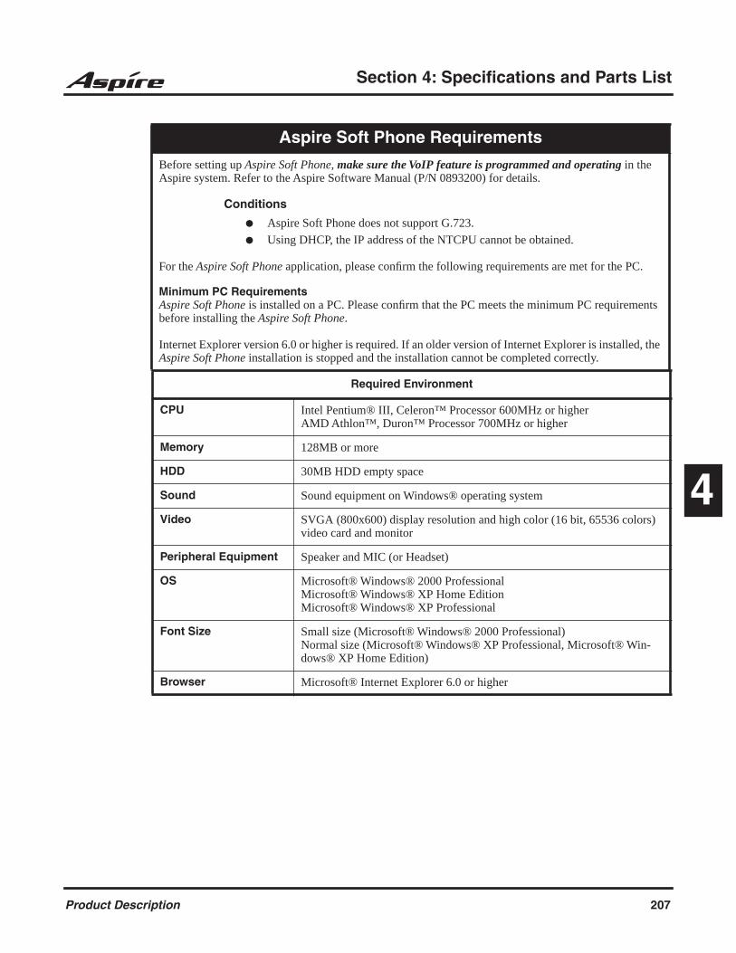
Section 4: Specifications and Parts List
4
Aspire Soft Phone Requirements
Before setting up Aspire Soft Phone, make sure the VoIP feature is programmed and operating in the Aspire system. Refer to the Aspire Software Manual (P/N 0893200) for details.
Conditions
Aspire Soft Phone does not support G.723.
Using DHCP, the IP address of the NTCPU cannot be obtained.
For the Aspire Soft Phone application, please confirm the following requirements are met for the PC.
Minimum PC RequirementsAspire Soft Phone is installed on a PC. Please confirm that the PC meets the minimum PC requirements before installing the Aspire Soft Phone.
Internet Explorer version 6.0 or higher is required. If an older version of Internet Explorer is installed, the Aspire Soft Phone installation is stopped and the installation cannot be completed correctly.
Required Environment
CPU Intel Pentium® III, Celeron™ Processor 600MHz or higherAMD Athlon™, Duron™ Processor 700MHz or higher
Memory 128MB or more
HDD 30MB HDD empty space
Sound Sound equipment on Windows® operating system
Video SVGA (800x600) display resolution and high color (16 bit, 65536 colors) video card and monitor
Peripheral Equipment Speaker and MIC (or Headset)
OS Microsoft® Windows® 2000 ProfessionalMicrosoft® Windows® XP Home EditionMicrosoft® Windows® XP Professional
Font Size Small size (Microsoft® Windows® 2000 Professional)Normal size (Microsoft® Windows® XP Professional, Microsoft® Win-dows® XP Home Edition)
Browser Microsoft® Internet Explorer 6.0 or higher
Product Description 207

Section 4: Specifications and Parts List
CallAnalyst Requirements
Ultra Call AnalystMinimum PC Requirements• PC with Pentium Processor• 256 MB RAM• VGA monitor 800 x 600 resolution (recommended SVGA 1024 x 768)• Windows Operating Software - 95/98/ME, NT-SP 3 or later, 2000, XP• 500 MB of free hard drive space• CD-ROM drive (for software installation)• Available serial port and RS-232 cable• Printer (if required to print reports)
CallAnalyst Enterprise Server
Main Server Minimum PC RequirementsHardware• PC with Pentium 4 Processor• 512 MB RAM• SVGA Monitor with 1024 x 768 resolution• 2 GB of free hard drive space• CD-ROM drive (for software installation)• Available serial port and RS-232 cable (if required)• Network Interface Card (NIC)• Printer (if required to print reports)
Software• Windows NT 4.0 (workstation or server) w/SP6, 2000 Professional w/SP3, XP Professional w/ SP1
or 2003 Server• MS SQL Server 2000 or MSDE (Microsoft Database Engine) for the database (MSDE is included on
the application CD)• Microsoft Internet Explorer 5.0 or higher (Internet Explorer is included on the application CD)
Network Client / Remote Site Reporting Client Minimum PC RequirementsHardware• PC with Pentium III Processor• 256 MB RAM• 1 GB of free hard drive space• CD-ROM drive (for software installation)• Network Interface Card (NIC)• Available serial port and RS-232 cable (if required)
Software• Windows NT 4.0 w/ SP6, or 2000 Professional w/ SP3, XP Professional w/ SP1 or 2003 Server• Microsoft Internet Explorer 5.0 or higher (Internet Explorer is included on the application CD)
208 Product Description

Section 4: Specifications and Parts List
4
inDepth RequirementsinDepth Server Requirements
Minimum Recommended
Computer/Processor Pentium II 300 Megahertz (MHz) or equivalent
Pentium III 700 Megahertz (MHz) or above
Memory RAM requirements depend on the operating system used:
Windows 98 Second Edition Windows Millennium Edition Windows XP Home Edition Microsoft Windows NT4 Windows 2000 Professional Windows XP Professional
32 MB64 MB128 MB64 MB64 MB128 MB
64 MB128 MB128 MB128 MB128 MB128 MB
Hard Disk Free Space Hard disk space requirements will vary depending on the operating system configuration and call traffic:
2 GB 10 GB
Graphics Card 256 color resolution 800 x 600 (SVGA)
256 color resolution 800 x 600 (SVGA) or above
Video Monitor 14” 17” or above
CD-ROM Drive Installed Installed
Network Card 10 Mbps 100 Mbps
Uninterruptible Power Supply No Yes
Additional Software: Internet Explorer Version 4 Version 6
Backup N/A CD-R, Tape or Network
Serial Ports Serial port requirements dependant upon configuration.
Events from Switch Physical Wallboard External Modem
111
Parallel Ports (Free) 1
Microsoft Network Required
TCP/IP - Each PC must have TCP/IP installed.- Each inDepth PC must have a unique IP address- If running a networked inDepth system, each inDepth. PC must be able to communications with each other inDepth PC via TCP/IP.- It is recommended that name resolution be implemented.
Static IP Address Required
Network File Sharing Enabled
Remote Support Software Connection
PC Anywhere Version 9 or AboveDirect Telephone Line or Remote Access Server
Product Description 209

Section 4: Specifications and Parts List
inDepth Requirements (cont’d)
inDepth Client - Sub-Supervisor Requirements
Minimum Recommended
Computer/Processor Pentium II 300 Megahertz (MHz) or equivalent
Pentium III 700 Megahertz (MHz) or above
Operating System • Windows 98 Second Edition
• Windows Millennium Edition
• Windows XP Home Edition
• Microsoft Windows NT4 with Service Pack 6a
• Windows 2000 Professional SR-3
• Windows XP Professional
Memory RAM requirements depend on the operating system used:
Windows 98 Second Edition Windows Millennium Edition Windows XP Home Edition Microsoft Windows NT4 Windows 2000 Professional Windows XP Professional
32 MB64 MB128 MB64 MB64 MB128 MB
64 MB128 MB128 MB128 MB128 MB128 MB
Hard Disk Free Space Hard disk space requirements will vary depending on the operating system configuration and call traffic:
30 MB 30 MB
Graphics Card 256 color resolution 800 x 600 (SVGA)
256 color resolution 800 x 600 (SVGA) or above
Video Monitor 14” 17” or above
Network Card 10 Mbps 100 Mbps
Uninterruptible Power Supply No Yes
Additional Software: Internet Explorer Version 4 Version 6
Installation CD-ROM or Network Drive CD-ROM or Network Drive
Serial Ports Serial port requirements dependant upon configuration.
Physical Wallboard 1
Microsoft Network Required
TCP/IP Installed
* The above requirements are based on systems with no other applications installed. If you run other applications, you may need to increase processor speed, memory and hard disk space accordingly.
210 Product Description

Section 4: Specifications and Parts List
4
inDepth Requirements (cont’d)
inDepth Client - inView LAN Wallboard Requirements
Minimum Recommended
Computer/Processor Pentium II 300 Megahertz (MHz) or equivalent
Operating System • Windows Millennium Edition• Windows XP Home Edition• Microsoft Windows NT4 with Service Pack 6a• Windows 2000 Professional SR-3• Windows XP Professional
Memory RAM requirements depend on the operating system used:
Windows Millennium Edition Windows XP Home Edition Microsoft Windows NT4 Windows 2000 Professional Windows XP Professional
64 MB128 MB64 MB64 MB128 MB
Hard Disk Free Space 30 MB 30 MB
Graphics Card 256 color resolution 800 x 600 (SVGA)
Video Monitor 14”
Network Card 10 Mbps
Uninterruptible Power Supply No
Additional Software: Internet Explorer Version 4
Installation CD-ROM or Network Drive
Microsoft Network Required
TCP/IP Installed
* The above requirements are based on systems with no other applications installed. If you run other applications, you may need to increase processor speed, memory and hard disk space accordingly.
Product Description 211
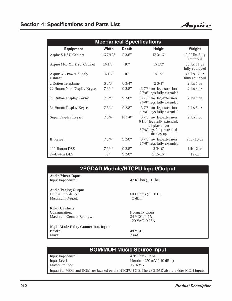
Section 4: Specifications and Parts List
Mechanical SpecificationsEquipment Width Depth Height Weight
Aspire S KSU Cabinet 16 7/16” 5 3/8” 13 3/16” 13.22 lbs fully equipped
Aspire M/L/XL KSU Cabinet 16 1/2” 10” 15 1/2” 55 lbs 11 oz fully equipped
Aspire XL Power Supply Cabinet
16 1/2” 10” 15 1/2” 45 lbs 12 oz fully equipped
2 Button Telephone 6 3/8” 8 3/4” 2 3/4” 2 lbs 1 oz
22 Button Non-Display Keyset 7 3/4” 9 2/8” 3 7/8” no leg extension5 7/8” legs fully extended
2 lbs 4 oz
22 Button Display Keyset 7 3/4” 9 2/8” 3 7/8” no leg extension5 7/8” legs fully extended
2 lbs 4 oz
34 Button Display Keyset 7 3/4” 9 2/8” 3 7/8” no leg extension5 7/8” legs fully extended
2 lbs 5 oz
Super Display Keyset 7 3/4” 10 7/8” 3 7/8” no leg extension6 1/8” legs fully extended,
display down7 7/8”legs fully extended,
display up
2 lbs 7 oz
IP Keyset 7 3/4” 9 2/8” 3 7/8” no leg extension5 7/8” legs fully extended
2 lbs 13 oz
110-Button DSS 7 3/4” 9 2/8” 3 3/16” 1 lb 12 oz
24-Button DLS 2” 9 2/8” 2 15/16” 12 oz
2PGDAD Module/NTCPU Input/OutputAudio/Music InputInput Impedance: 47 KOhm @ 1Khz
Audio/Paging OutputOutput Impedance:Maximum Output:
600 Ohms @ 1 KHz+3 dBm
Relay ContactsConfiguration:Maximum Contact Ratings:
Normally Open24 VDC, 0.5A120 VAC, 0.25A
Night Mode Relay Connection, InputBreak:Make:
48 VDC7 mA
BGM/MOH Music Source InputInput Impedance:Input Level:Maximum Input:
47KOhm / 1KhzNominal 250 mV (-10 dBm)1V RMS
Inputs for MOH and BGM are located on the NTCPU PCB. The 2PGDAD also provides MOH inputs.
212 Product Description
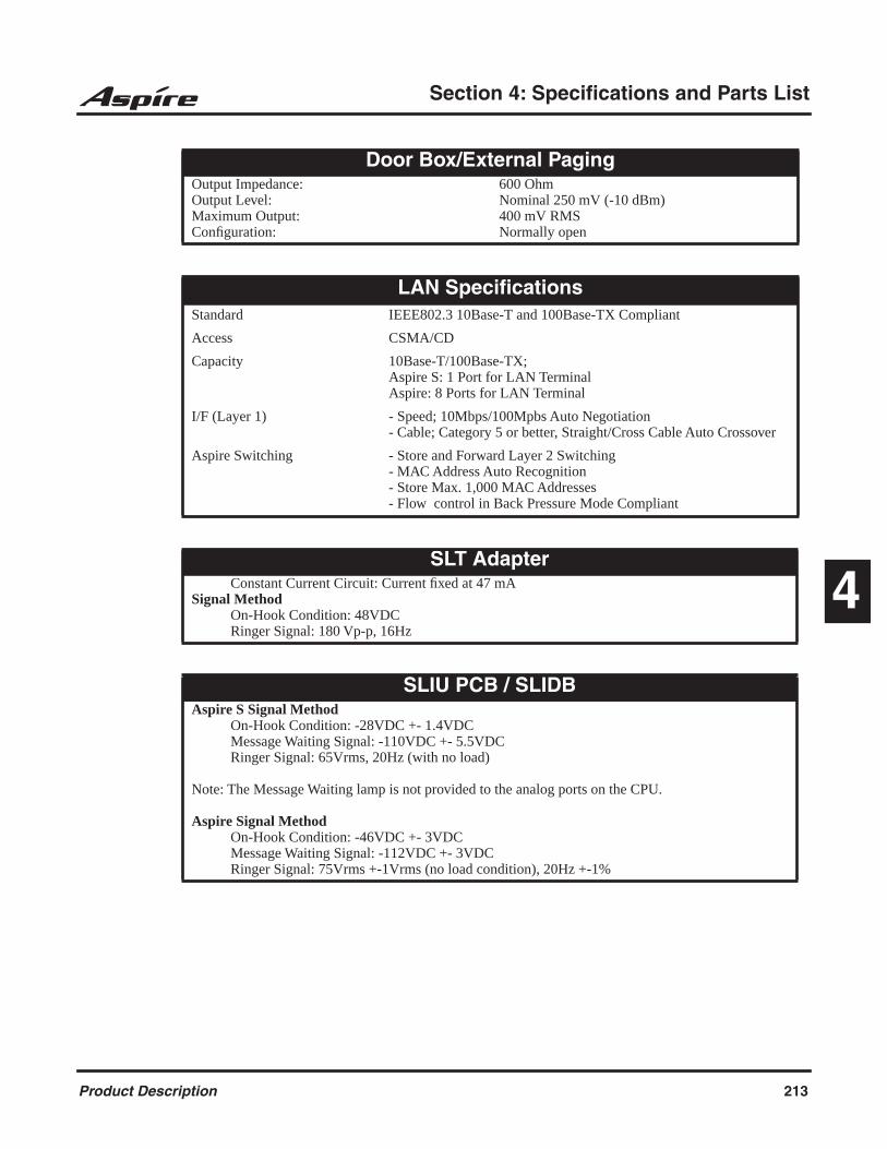
Section 4: Specifications and Parts List
4
Door Box/External PagingOutput Impedance:Output Level:Maximum Output:Configuration:
600 OhmNominal 250 mV (-10 dBm)400 mV RMSNormally open
LAN SpecificationsStandard IEEE802.3 10Base-T and 100Base-TX Compliant
Access CSMA/CD
Capacity 10Base-T/100Base-TX; Aspire S: 1 Port for LAN TerminalAspire: 8 Ports for LAN Terminal
I/F (Layer 1) - Speed; 10Mbps/100Mpbs Auto Negotiation- Cable; Category 5 or better, Straight/Cross Cable Auto Crossover
Aspire Switching - Store and Forward Layer 2 Switching- MAC Address Auto Recognition- Store Max. 1,000 MAC Addresses- Flow control in Back Pressure Mode Compliant
SLT AdapterConstant Current Circuit: Current fixed at 47 mA
Signal MethodOn-Hook Condition: 48VDCRinger Signal: 180 Vp-p, 16Hz
SLIU PCB / SLIDBAspire S Signal Method
On-Hook Condition: -28VDC +- 1.4VDCMessage Waiting Signal: -110VDC +- 5.5VDCRinger Signal: 65Vrms, 20Hz (with no load)
Note: The Message Waiting lamp is not provided to the analog ports on the CPU.
Aspire Signal MethodOn-Hook Condition: -46VDC +- 3VDCMessage Waiting Signal: -112VDC +- 3VDCRinger Signal: 75Vrms +-1Vrms (no load condition), 20Hz +-1%
Product Description 213
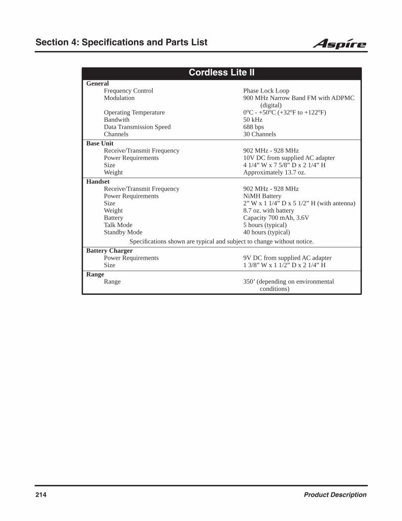
Section 4: Specifications and Parts List
Cordless Lite IIGeneral
Frequency ControlModulation
Operating TemperatureBandwithData Transmission SpeedChannels
Phase Lock Loop900 MHz Narrow Band FM with ADPMC
(digital)0oC - +50oC (+32oF to +122oF)50 kHz688 bps30 Channels
Base UnitReceive/Transmit FrequencyPower RequirementsSizeWeight
902 MHz - 928 MHz10V DC from supplied AC adapter4 1/4” W x 7 5/8” D x 2 1/4” HApproximately 13.7 oz.
HandsetReceive/Transmit FrequencyPower RequirementsSizeWeightBatteryTalk ModeStandby Mode
902 MHz - 928 MHzNiMH Battery2” W x 1 1/4” D x 5 1/2” H (with antenna)8.7 oz. with batteryCapacity 700 mAh, 3.6V5 hours (typical)40 hours (typical)
Specifications shown are typical and subject to change without notice.
Battery ChargerPower RequirementsSize
9V DC from supplied AC adapter1 3/8” W x 1 1/2” D x 2 1/4” H
RangeRange 350’ (depending on environmental
conditions)
214 Product Description

Section 4: Specifications and Parts List
4
Cordless IIGeneral
Frequency ControlModulationOperating TemperatureOutput PowerOccupied BandwithData Transmission SpeedChannels
Phase Lock LoopDigital Spread Spectrum0oC - +50oC (+32oF to +122oF)60 mW+ 500 KHz688 bps10 Channels
Base UnitReceive/Transmit FrequencyPower RequirementsSizeWeight
902 MHz - 928 MHz10V DC from supplied AC adapter4 1/4” W x 7 5/8” D x 2 1/4” H11.8 oz.
HandsetReceive/Transmit FrequencyPower RequirementsSizeWeightBatteryCharging TimeTalk ModeStandby Mode
902 MHz - 928 MHzNickel-Cadmium Battery Pack2 1/4” W x 1 1/2” D x 6 5/16” H8.6 oz.Capacity 800 mAh, 3.6V5-6 hours max. to full charge6 hours (typical)4 days (typical)
Specifications shown are typical and subject to change without notice.
Battery ChargerPower RequirementsSizeWeight
9V DC from supplied AC adapter4 3/4” W x 4 1/2” D x 3 1/2” H6.5 oz.
RangeRange 350’ (depending on environmental
conditions)
UL Listed SystemA label will be affixed to the product with the letters UL inside a circle which is the symbol used by UL to indicate that a product is UL Listed. If you see a small “c” outside the symbol, then the product also meets the requirements for Canada.
Product Description 215

Section 4: Specifications and Parts List
FCC Registration InformationManufacturer:FCC Part 15 Registration:
NEC Infrontia, Inc.Class A
Model:FCC Registration Number: (Refer to the label on the System Cabinet for the FCC Registration Number.
Aspire SKF: US:NIFKF06BASPIRESMF: US:NIFMF06BASPIRESPF: US:NIFPF06BASPIRES
Reg.Status
Facility Interface Code (FIC)
Mfrs. PortIdentifier
RingerEq. Number
Service Order Code
(SOC)
NetworkJacks
Original 02LS2, 02IS2 4COIU 0.6B 9.0F, 6.0P RJ21X
Model:FCC Registration Number: (Refer to the label on the Main Cabinet for the FCC Registration Number.
AspireKF: US:NIFKF07BASPIREMF: US:NIFMF07BASPIREPF: US:NIFPF07BASPIRE
Reg.Status
Facility Interface Code (FIC)
Mfrs. PortIdentifier
RingerEq. Number
Service Order Code
(SOC)
NetworkJacks
Original 02LS2 4COIU-LS1 0.7B 9.0F RJ21X
Original 02LS2 8COIU-LS1 0.7B 9.0F RJ21X
Original 02GS2 4COIU-LG1 0.7B 9.0F RJ21X
Original 02GS2 8COIU-LG1 0.7B 9.0F RJ21X
Original 02RV2-T 4DIOPU --- AS.2 RJ21X
Original 02RV2-T 8DIOPU --- AS.2 RJ21X
Reg.Status
Analog PrivateLine Interfaces
Mfrs. PortIdentifier
Service Order Code
(SOC)
NetworkJacks
Original TL11M 4TLIU --- 9.0F RJ2EX
216 Product Description
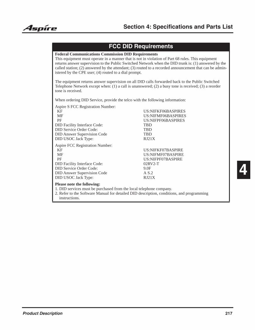
Section 4: Specifications and Parts List
4
FCC DID RequirementsFederal Communications Commission DID RequirementsThis equipment must operate in a manner that is not in violation of Part 68 rules. This equipment returns answer supervision to the Public Switched Network when the DID trunk is: (1) answered by the called station; (2) answered by the attendant; (3) routed to a recorded announcement that can be admin-istered by the CPE user; (4) routed to a dial prompt.
The equipment returns answer supervision on all DID calls forwarded back to the Public Switched Telephone Network except when: (1) a call is unanswered; (2) a busy tone is received; (3) a reorder tone is received.
When ordering DID Service, provide the telco with the following information:
Aspire S FCC Registration Number: KF MF PFDID Facility Interface Code:DID Service Order Code:DID Answer Supervision CodeDID USOC Jack Type:
US:NIFKF06BASPIRESUS:NIFMF06BASPIRESUS:NIFPF06BASPIRESTBDTBDTBDRJ21X
Aspire FCC Registration Number: KF MF PFDID Facility Interface Code:DID Service Order Code:DID Answer Supervision CodeDID USOC Jack Type:
US:NIFKF07BASPIREUS:NIFMF07BASPIREUS:NIFPF07BASPIRE02RV2-T9.0FA S.2RJ21X
Please note the following:1. DID services must be purchased from the local telephone company.2. Refer to the Software Manual for detailed DID description, conditions, and programming instructions.
Product Description 217
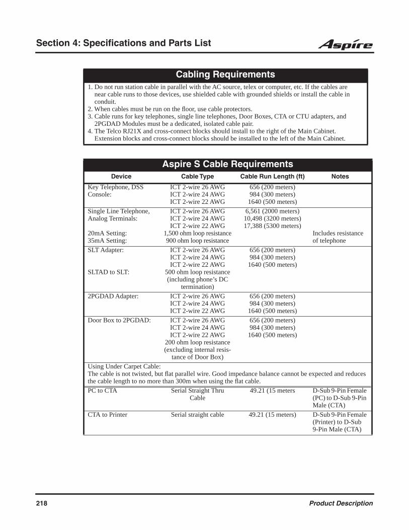
Section 4: Specifications and Parts List
Cabling Requirements1. Do not run station cable in parallel with the AC source, telex or computer, etc. If the cables are near cable runs to those devices, use shielded cable with grounded shields or install the cable in conduit.2. When cables must be run on the floor, use cable protectors.3. Cable runs for key telephones, single line telephones, Door Boxes, CTA or CTU adapters, and 2PGDAD Modules must be a dedicated, isolated cable pair.4. The Telco RJ21X and cross-connect blocks should install to the right of the Main Cabinet. Extension blocks and cross-connect blocks should be installed to the left of the Main Cabinet.
Aspire S Cable RequirementsDevice Cable Type Cable Run Length (ft) Notes
Key Telephone, DSS Console:
ICT 2-wire 26 AWGICT 2-wire 24 AWGICT 2-wire 22 AWG
656 (200 meters)984 (300 meters)1640 (500 meters)
Single Line Telephone, Analog Terminals:
20mA Setting:35mA Setting:
ICT 2-wire 26 AWGICT 2-wire 24 AWGICT 2-wire 22 AWG
1,500 ohm loop resistance900 ohm loop resistance
6,561 (2000 meters)10,498 (3200 meters)17,388 (5300 meters)
Includes resistance of telephone
SLT Adapter:
SLTAD to SLT:
ICT 2-wire 26 AWGICT 2-wire 24 AWGICT 2-wire 22 AWG
500 ohm loop resistance(including phone’s DC
termination)
656 (200 meters)984 (300 meters)1640 (500 meters)
2PGDAD Adapter: ICT 2-wire 26 AWGICT 2-wire 24 AWGICT 2-wire 22 AWG
656 (200 meters)984 (300 meters)1640 (500 meters)
Door Box to 2PGDAD: ICT 2-wire 26 AWGICT 2-wire 24 AWGICT 2-wire 22 AWG
200 ohm loop resistance(excluding internal resis-
tance of Door Box)
656 (200 meters)984 (300 meters)1640 (500 meters)
Using Under Carpet Cable:The cable is not twisted, but flat parallel wire. Good impedance balance cannot be expected and reduces the cable length to no more than 300m when using the flat cable.
PC to CTA Serial Straight Thru Cable
49.21 (15 meters D-Sub 9-Pin Female (PC) to D-Sub 9-Pin Male (CTA)
CTA to Printer Serial straight cable 49.21 (15 meters) D-Sub 9-Pin Female (Printer) to D-Sub 9-Pin Male (CTA)
218 Product Description

Section 4: Specifications and Parts List
4
CPU to PC: Serial cross cable 49.21 (15 meters) D-Sub 9-Pin Female (PC) to D-Sub 9-Pin Male (CPU)
4-wire LAN (UTP) cable with category 3 or higher for 10Base-T, and cate-gory 5 or higher for 100
Base-TXEthernet cross cable
328.08 (100 meters)
CPU to Switching Hub: 4-wire LAN (UTP) cable with category 3 or higher for 10Base-T, and cate-gory 5 or higher for 100
Base-TXEthernet straight cable
328.08 (100 meters)
CPU to Printer: Serial cross cable 49.21 (15 meters) D-Sub 9-Pin Female (Printer) to D-Sub 9-Pin Male (CPU)
IP Telephone LAN (UTP) cable with category 3 or higher for 10Base-T, and category 5 or higher for 100 Base-TX
328.08 (100 meters) Regardless of whether it receives power from the AC adapter or switch-ing hub.
VOIPU PCB to IP Telephone
Standard Ethernet Cable (cross cable)
328 (100 meters)
VOIPU PCB to Router Standard Ethernet Cable( straight cable)
328 (100 meters)
PSA Adapter ICT 2-wire 4,547 (1,386 meters) Includes DC resis-tance of outside line - excludes internal resistance of IP tele-phone
ENTU PCB to PC Standard Ethernet Cable (cross-cable)
328 (100 meters)
ENTU to Switching Hub Standard Ethernet Cable(straight-cable)
328 (100 meters)
DID Trunks: ICT 2-wire 24 AWG
Loop resistance (DP only)9842 ohm @35mA500 ohm @20 mA
20,997 (6400 meters) Includes SLT or exchangeIncludes resistance of telephone
2BRIU to ISDN Terminals:
ICT 4-wire 24 AWG 328 (100 meters) with Point-Multipoint short connection984 (300 meters)300m with Point-Multipoint long connection1,640 (500 meters) with Point-Point connection
Aspire S Cable RequirementsDevice Cable Type Cable Run Length (ft) Notes
Product Description 219
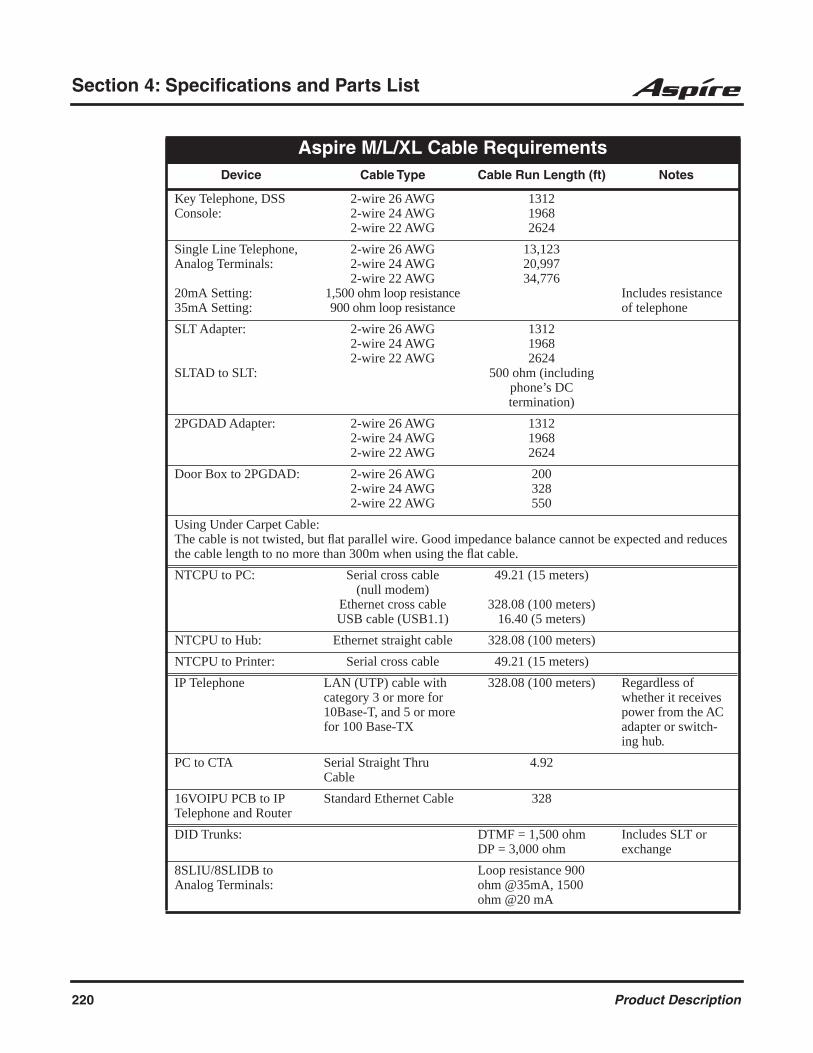
Section 4: Specifications and Parts List
Aspire M/L/XL Cable RequirementsDevice Cable Type Cable Run Length (ft) Notes
Key Telephone, DSS Console:
2-wire 26 AWG2-wire 24 AWG2-wire 22 AWG
131219682624
Single Line Telephone, Analog Terminals:
20mA Setting:35mA Setting:
2-wire 26 AWG2-wire 24 AWG2-wire 22 AWG
1,500 ohm loop resistance900 ohm loop resistance
13,12320,99734,776
Includes resistance of telephone
SLT Adapter:
SLTAD to SLT:
2-wire 26 AWG2-wire 24 AWG2-wire 22 AWG
131219682624
500 ohm (including phone’s DC termination)
2PGDAD Adapter: 2-wire 26 AWG2-wire 24 AWG2-wire 22 AWG
131219682624
Door Box to 2PGDAD: 2-wire 26 AWG2-wire 24 AWG2-wire 22 AWG
200328550
Using Under Carpet Cable:The cable is not twisted, but flat parallel wire. Good impedance balance cannot be expected and reduces the cable length to no more than 300m when using the flat cable.
NTCPU to PC: Serial cross cable (null modem)
Ethernet cross cableUSB cable (USB1.1)
49.21 (15 meters)
328.08 (100 meters)16.40 (5 meters)
NTCPU to Hub: Ethernet straight cable 328.08 (100 meters)
NTCPU to Printer: Serial cross cable 49.21 (15 meters)
IP Telephone LAN (UTP) cable with category 3 or more for 10Base-T, and 5 or more for 100 Base-TX
328.08 (100 meters) Regardless of whether it receives power from the AC adapter or switch-ing hub.
PC to CTA Serial Straight Thru Cable
4.92
16VOIPU PCB to IP Telephone and Router
Standard Ethernet Cable 328
DID Trunks: DTMF = 1,500 ohmDP = 3,000 ohm
Includes SLT or exchange
8SLIU/8SLIDB to Analog Terminals:
Loop resistance 900 ohm @35mA, 1500 ohm @20 mA
220 Product Description
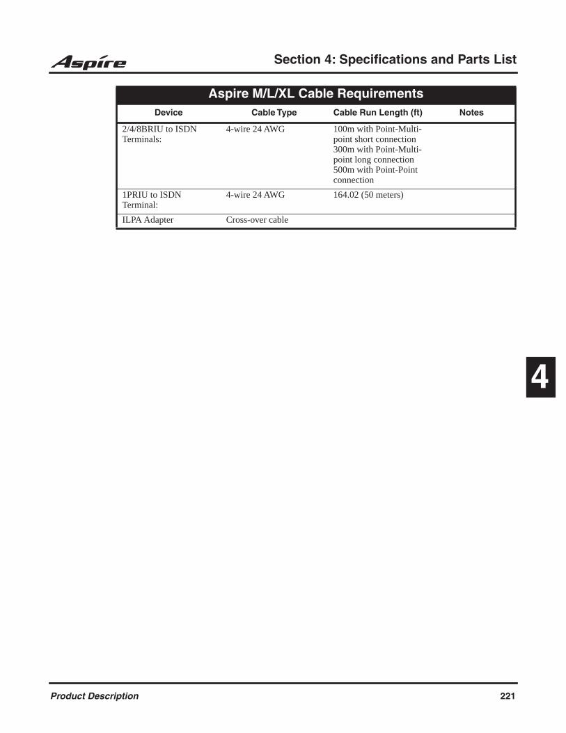
Section 4: Specifications and Parts List
4
2/4/8BRIU to ISDN Terminals:
4-wire 24 AWG 100m with Point-Multi-point short connection300m with Point-Multi-point long connection500m with Point-Point connection
1PRIU to ISDN Terminal:
4-wire 24 AWG 164.02 (50 meters)
ILPA Adapter Cross-over cable
Aspire M/L/XL Cable RequirementsDevice Cable Type Cable Run Length (ft) Notes
Product Description 221

Section 4: Specifications and Parts List
Aspire S Configuration Guide
System Cabinet
Slot Assignment
CP
U
1 2 3 4 5 6 7 8
8-Channel Digital/Analog Slots
Dig
ital
Po
rts
1-8
An
alo
g P
ort
s
1
-2
* Slots 1 and 2 are fixed - these are located on the CPU and are part of the basic system.
222 Product Description

Section 4: Specifications and Parts List
4
Aspire M/L/XL Configuration Guide
Expansion Cabinet
Slot Assignment
EX
IFU
Exp
ansi
on
Inte
rfac
e
1 2 3 4 5 6 7 8
Main Cabinet
Slot Assignment
NT
CP
U
1 2 3 4 5 6 7 8
32-Channel Digital/Analog Slots
32-Channel Digital/Analog Slots
Qty 1 - P/N 0891000 Qty 2 - P/N 0891000 Qty 1 - P/N 0892011 and P/N 0892012
Power Supply Type
Qty 1 - P/N 0891000 Qty 2 - P/N 0891000 Qty 1 - P/N 0892011 and P/N 0892012
Power Supply Type
Product Description 223

Section 4: Specifications and Parts List
Parts List
Station Equipment Description Part Number
2-Button Telephone - Black2-Button Telephone - White22-Button Handsfree Non-Display Telephone - Black22-Button Handsfree Non-Display Telephone - White22-Button Handsfree Display Telephone - Black22-Button Handsfree Display Telephone - White34-Button Handsfree Display Telephone - Black34-Button Handsfree Display Telephone - White34-Button Super Display Telephone - Black34-Button Super Display Telephone - White34-Button Aspire IPhone - Black24-Button DLS Console - Black24-Button DLS Console - White110-Button DSS Console - Black110-Button DSS Console - WhiteNEC H.323 IP TelephoneNEC H.323 IP Telephone AC AdapterAnalog Telephones: DTR-1-1 (BK) Single Line Telephone with redial, flash, mw lamp, data jack ringer/handset volume control - Black DTR-1-1 (WH) Single Line Telephone with redial, flash, mw lamp, data jack ringer/handset volume control - White DTR-1HM-1 (BK). Same as P/N 780020 with 8 programmable feature/speed dial keys - Black DTR-1HM-1 (WH). Same as 780021 with 8 programmable feature/ speed dial keys - White DTH-1-1 (BK) Single line telephone with 4 programmable feature/ speed dial keys, mw lamp, redial, flash & mute keys
089004708900480890041089004208900430890044089004508900460890049089005008900650890053089005408900510890052780005780600
780020
780021
780025
780026
780034
224 Product Description
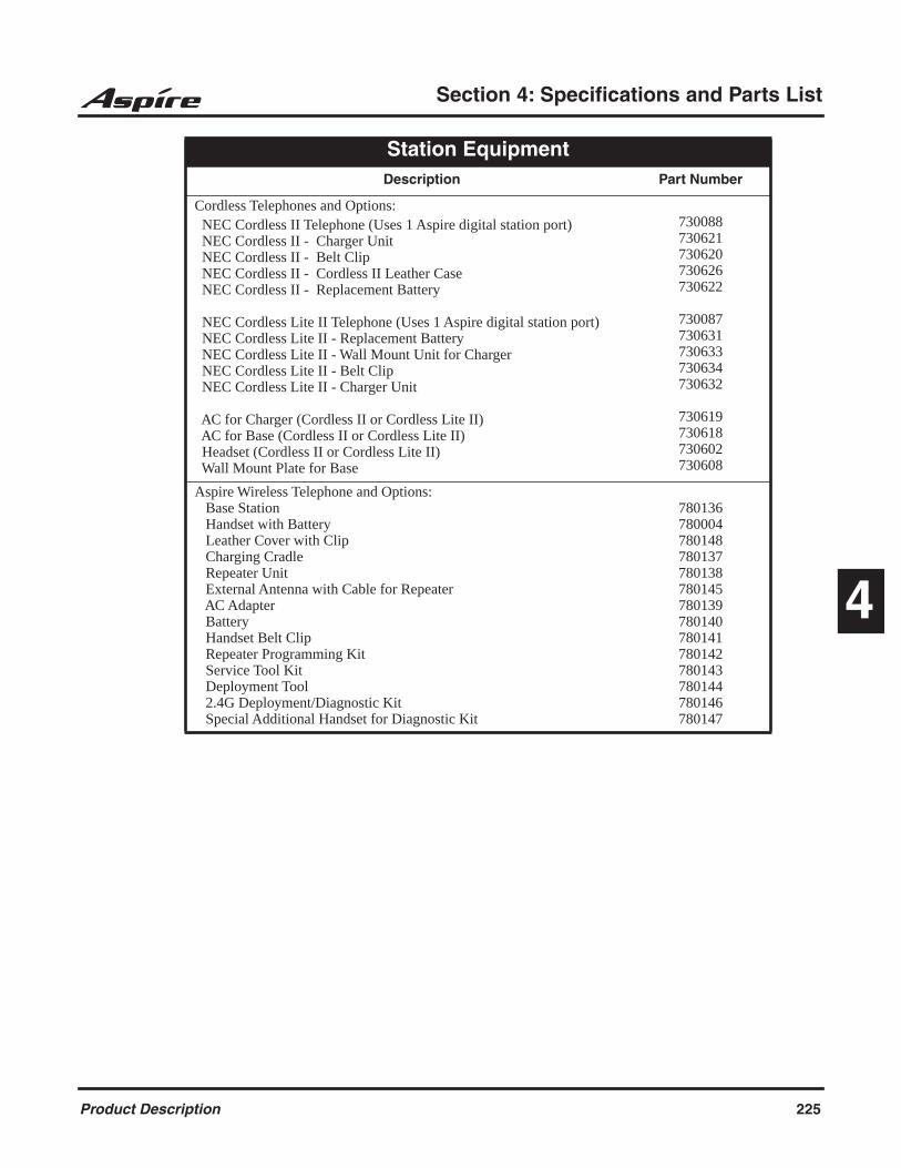
Section 4: Specifications and Parts List
4
Cordless Telephones and Options: NEC Cordless II Telephone (Uses 1 Aspire digital station port) NEC Cordless II - Charger Unit NEC Cordless II - Belt Clip NEC Cordless II - Cordless II Leather Case NEC Cordless II - Replacement Battery
NEC Cordless Lite II Telephone (Uses 1 Aspire digital station port) NEC Cordless Lite II - Replacement Battery NEC Cordless Lite II - Wall Mount Unit for Charger NEC Cordless Lite II - Belt Clip NEC Cordless Lite II - Charger Unit
AC for Charger (Cordless II or Cordless Lite II) AC for Base (Cordless II or Cordless Lite II) Headset (Cordless II or Cordless Lite II) Wall Mount Plate for Base
730088730621730620730626730622
730087730631730633730634730632
730619730618730602730608
Aspire Wireless Telephone and Options: Base Station Handset with Battery Leather Cover with Clip Charging Cradle Repeater Unit External Antenna with Cable for Repeater AC Adapter Battery Handset Belt Clip Repeater Programming Kit Service Tool Kit Deployment Tool 2.4G Deployment/Diagnostic Kit Special Additional Handset for Diagnostic Kit
780136780004780148780137780138780145780139780140780141780142780143780144780146780147
Station Equipment Description Part Number
Product Description 225

Section 4: Specifications and Parts List
Peripheral Station EquipmentDescription Part Number
2PGDAD Module (for Door Box/Page/ACI)AC Adapter (AC-2R)Analog Interface with Ringing Adapter (APR) (Requires P/N 780135 AC-2R Adapter)Analog Interface without Ringing Adapter (APA)Call Recording Adapter (ADA)Door BoxHeadsets (Modular): Polaris™ Supra® Monaural, Noise Cancelling
Polaris™ Supra® Binaural, Noise Cancelling Polaris™ Supra Monaural Polaris™ Encore Monaural - Voice Tube
Polaris™ Encore® Binaural, Noise Cancelling Polaris Tristar - Voice Tube Polaris Mirage - Voice Tube CT-11 Cordless Headset Telephone Polaris Headset Accessories: Ear Cushion (Pkg of 2) Clothing Clip Wind Screen Clear Voice Tube for Encore and Tristar Clear Voice Tube for Mirage and Supra Polaris Extension Cable Rainbow Voice Tube Pack for Encore and Tristar (Pkg of 6) Rainbow Voice Tube Pack for Mirage and Supra (Pkg of 6)IP Adapter (IP)In-Line Power Adapter (ILPA)NEC Audio Emcee: Audio Emcee Replacement Audio Emcee Remote Replacement RCA CablePower Failure Adapter for IP Telephone (PSA)Recording Adapter for IP Telephone (ADA2)RS-232C Adapter (CTA)SLT AdapterSpeakerphone Adapter - Black (Requires P/N 780135 AC-2R Adapter)Speakerphone Adapter - White (Requires P/N 780135 AC-2R Adapter)USB Adapter (CTU) (Requires P/N 780135 AC-2R Adapter)Voice Security Recorder (VSR) with USB Cable and Software
0891027
7801350890056
0890057089005592245
750636 750633750632750634 750635750630750631730089
7506567506577506507506527506517506557506547506530890060780122
7503167503177503180890067089006608900580891026089006208900630890059780275
226 Product Description

Section 4: Specifications and Parts List
4
Aspire ApplicationsDescription Part Number
Aspire Soft Phone Software on CD NEC USB HandsetNEC USB Headset
0893641780094750638
inDepth/inDepth Plus - Aspire M/L/XL Only Aspire inDepth Lite Software (Dongle and Software) Aspire inDepth Software (Dongle and Software) Aspire inDepth+ Software (Dongle and Software) Aspire inDepth Supervisor Aspire inDepth Lite to inDepth Upgrade Aspire inDepth Lite to inDepth Plus Upgrade inDepth to inDepth Plus Upgrade inDepth Upgrade i-Series to Aspire Aspire inView for 5 Agents Aspire inView for 10 Agents Aspire inView for 15 Agents Aspire inView for 20 Agents Aspire inView for 25 Agents Aspire inView for 30 Agents Aspire inView for 40 Agents Aspire inView for 50 Agents Aspire inView Upgrade to Add 5 Agents Aspire inView Upgrade to Add 10 Agents Aspire inView Upgrade to Add 15 Agents Aspire inView Upgrade to Add 20 Agents Aspire inView Upgrade to Add 25 Agents Aspire inView Upgrade to Add 30 Agents Aspire inView Upgrade to Add 40 Agents Aspire inDepth/inDepth+ Demo CD
089214408921020892103089212508921410892142089214308921530892126089212708921280892129089213008921310892132089213308921340892135089213608921370892138089213908921400892101
Ultra CallAnalyst Ultra CallAnalyst Lite Ultra CallAnalyst Lite - to - Full Upgrade Ultra CallAnalyst Full Ultra CallAnalyst Full + 1 Clent Ultra CallAnalyst Additional 1 Client Ultra CallAnalyst Enterprise Additional Remote Site License Requires 0891095. Ultra CallAnalyst Enterprise Server & 120 Ports Ultra CallAnalyst Enterprise Remote Site License (with no Ports) Requires 0891095. Ultra CallAnalyst Enterprise Additional Port License Requires 0891095. Ultra CallAnalyst Enterprise Additional Network Client License Requires 0891095. Ultra CallAnalyst Enterprise Site Reporting Thin Client Requires 0891095.
089108108910820891083089108408910850891094
08910950891096
0891097
0891098
0891099
Product Description 227

Section 4: Specifications and Parts List
Aspire S Common EquipmentDescription Part Number
Aspire S 8 Slot KSUFloor/Desk Stand Mounting BracketMod 8 to 25 Pair (Unterminated) Installation Cable32 MB Compact Flash Card with System Software32 MB Compact Flash Card - BlankVRS Compact Flash CardIntraMail - 4 Port, 4 HourIntraMail - 8 Port, 8 HourNull Modem Cable for PCProCPU Battery56K Modem
0890005089130380892
089106508910640891040089217608921780892004
EX0254-004085862D
Aspire S PCBsDescription Part Number
Common CardsEthernet Option Daughter BoardDSP Resource Daughter Board
Trunk Interfaces4 CO Loop Start Trunk PCB2 DID/OPX PCB2 BRI PCB - Check with your NEC Sales Representative for availability.
Station Interfaces8 Aspire S Digital Station PCB4 Analog Station PCB4 Analog Station Expansion Daughter Board4 Channel VoIP Media Gateway PCB4 Channel VoIP Media Gateway Expansion Daughter Board
08910530891003
089104608910470891050
089105108910480891049
0891054B0891055B
Aspire S System BundlesDescription Part Number
Aspire S/NVM-2e - 2P Bundle Consists of: 1 - 0890005 Aspire S KSU 1 - 0891046 4 CO Loop Start Card 4 - 0890043 22B Display Tel (BK) 1 - 17780-2P - NVM-2e 2 Port VMAspire S/NVM-2e - 4P Bundle Consists of: 1 - 0890005 Aspire S KSU 1 - 0891046 4 CO Loop Start Card 1 - 0891048 4 Analog Station Card 4 - 0890043 22B Display Tel (BK) 1 - 17780-4P - NVM-2e 4 Port VM
0892031
0892032
228 Product Description
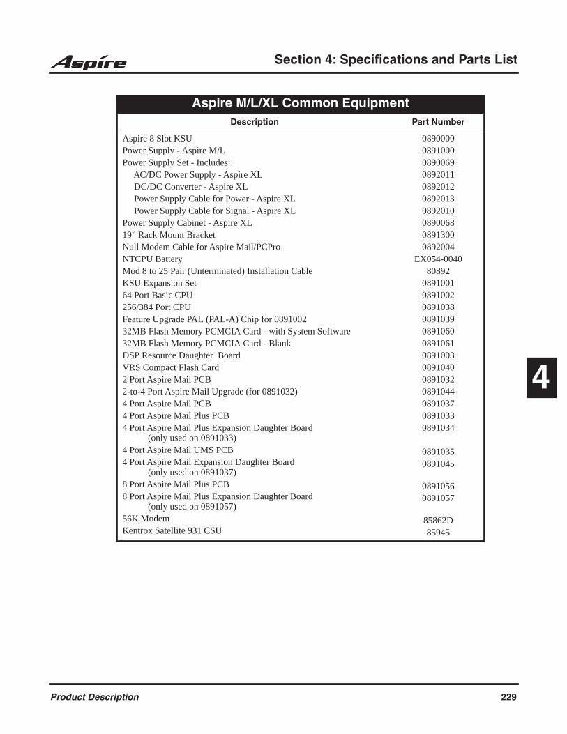
Section 4: Specifications and Parts List
4
Aspire M/L/XL Common EquipmentDescription Part Number
Aspire 8 Slot KSUPower Supply - Aspire M/LPower Supply Set - Includes: AC/DC Power Supply - Aspire XL DC/DC Converter - Aspire XL Power Supply Cable for Power - Aspire XL Power Supply Cable for Signal - Aspire XLPower Supply Cabinet - Aspire XL19” Rack Mount BracketNull Modem Cable for Aspire Mail/PCProNTCPU BatteryMod 8 to 25 Pair (Unterminated) Installation CableKSU Expansion Set64 Port Basic CPU256/384 Port CPUFeature Upgrade PAL (PAL-A) Chip for 089100232MB Flash Memory PCMCIA Card - with System Software32MB Flash Memory PCMCIA Card - BlankDSP Resource Daughter BoardVRS Compact Flash Card2 Port Aspire Mail PCB2-to-4 Port Aspire Mail Upgrade (for 0891032)4 Port Aspire Mail PCB4 Port Aspire Mail Plus PCB4 Port Aspire Mail Plus Expansion Daughter Board (only used on 0891033)4 Port Aspire Mail UMS PCB4 Port Aspire Mail Expansion Daughter Board (only used on 0891037)8 Port Aspire Mail Plus PCB8 Port Aspire Mail Plus Expansion Daughter Board (only used on 0891057)56K ModemKentrox Satellite 931 CSU
0890000089100008900690892011089201208920130892010089006808913000892004
EX054-004080892
0891001089100208910380891039089106008910610891003089104008910320891044089103708910330891034
08910350891045
08910560891057
85862D85945
Product Description 229
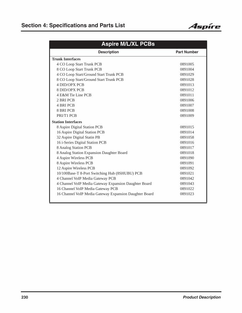
Section 4: Specifications and Parts List
Aspire M/L/XL PCBsDescription Part Number
Trunk Interfaces4 CO Loop Start Trunk PCB8 CO Loop Start Trunk PCB4 CO Loop Start/Ground Start Trunk PCB8 CO Loop Start/Ground Start Trunk PCB4 DID/OPX PCB8 DID/OPX PCB4 E&M Tie Line PCB2 BRI PCB4 BRI PCB8 BRI PCBPRI/T1 PCB
08910050891004089102908910280891013089101208910110891006089100708910080891009
Station Interfaces8 Aspire Digital Station PCB16 Aspire Digital Station PCB32 Aspire Digital Statin PB16 i-Series Digital Station PCB8 Analog Station PCB8 Analog Station Expansion Daughter Board4 Aspire Wireless PCB8 Aspire Wireless PCB12 Aspire Wireless PCB10/100Base-T 8-Port Switching Hub (8SHUBU) PCB4 Channel VoIP Media Gateway PCB4 Channel VoIP Media Gateway Expansion Daughter Board16 Channel VoIP Media Gateway PCB16 Channel VoIP Media Gateway Expansion Daughter Board
08910150891014089105808910160891017089101808910900891091089109208910210891042089104308910220891023
230 Product Description
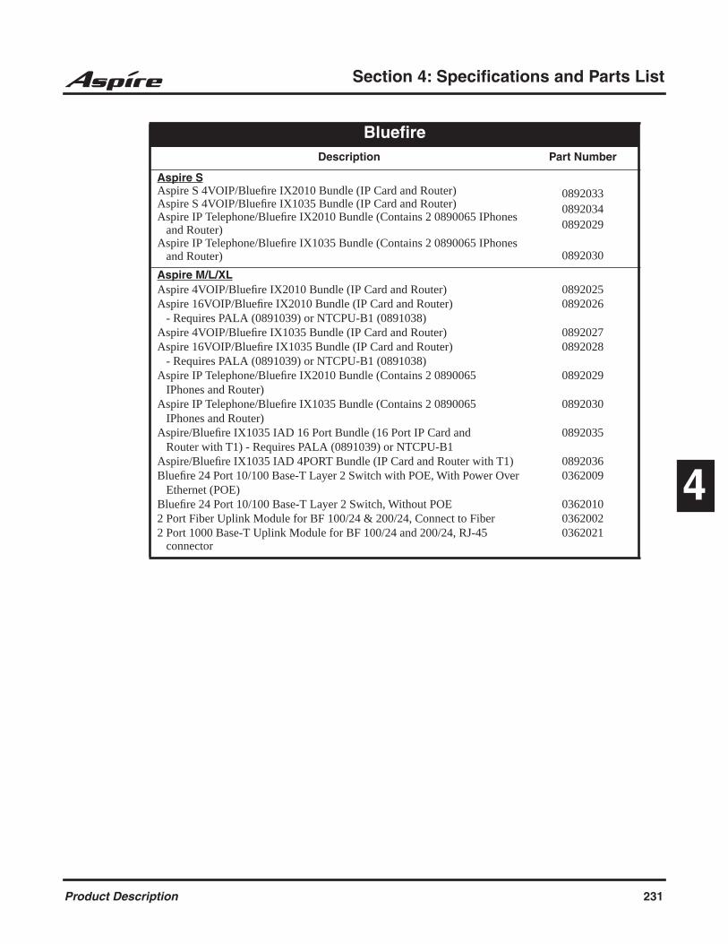
Section 4: Specifications and Parts List
4
Bluefire Description Part Number
Aspire SAspire S 4VOIP/Bluefire IX2010 Bundle (IP Card and Router)Aspire S 4VOIP/Bluefire IX1035 Bundle (IP Card and Router)Aspire IP Telephone/Bluefire IX2010 Bundle (Contains 2 0890065 IPhones and Router)Aspire IP Telephone/Bluefire IX1035 Bundle (Contains 2 0890065 IPhones and Router)
089203308920340892029
0892030
Aspire M/L/XLAspire 4VOIP/Bluefire IX2010 Bundle (IP Card and Router)Aspire 16VOIP/Bluefire IX2010 Bundle (IP Card and Router) - Requires PALA (0891039) or NTCPU-B1 (0891038)Aspire 4VOIP/Bluefire IX1035 Bundle (IP Card and Router)Aspire 16VOIP/Bluefire IX1035 Bundle (IP Card and Router) - Requires PALA (0891039) or NTCPU-B1 (0891038)Aspire IP Telephone/Bluefire IX2010 Bundle (Contains 2 0890065 IPhones and Router)Aspire IP Telephone/Bluefire IX1035 Bundle (Contains 2 0890065 IPhones and Router)Aspire/Bluefire IX1035 IAD 16 Port Bundle (16 Port IP Card and Router with T1) - Requires PALA (0891039) or NTCPU-B1Aspire/Bluefire IX1035 IAD 4PORT Bundle (IP Card and Router with T1)Bluefire 24 Port 10/100 Base-T Layer 2 Switch with POE, With Power Over Ethernet (POE)Bluefire 24 Port 10/100 Base-T Layer 2 Switch, Without POE2 Port Fiber Uplink Module for BF 100/24 & 200/24, Connect to Fiber2 Port 1000 Base-T Uplink Module for BF 100/24 and 200/24, RJ-45 connector
08920250892026
08920270892028
0892029
0892030
0892035
08920360362009
036201003620020362021
Product Description 231

Section 4: Specifications and Parts List
Desi Labels Description Part Number
Analog Telephones: Desi Labels for 780020/780021 - Black, Package of 25 Desi Labels for 780020/780021 - Green, Package of 25 Desi Labels for 780020/780021 - Silver, Package of 25 Desi Labels for 780020/780021 - White, Package of 25 Desi Labels for 780025/780026 - Black, Package of 25 Desi Labels for 780025/780026 - Green, Package of 25 Desi Labels for 780025/780026 - Silver, Package of 25 Desi Labels for 780025/780026 - White, Package of 25 Desi Labels for 780034 - Metal Silver, Package of 252-Button Telephones: Desi Label for 2BTN Tel-Silver (25-pkg), For Laser Jet printers only Desi Label for 2BTN Tel-Solid Silver (25-pkg), For Ink Jet and Laser Jet printers - solid silver Desi Label-2BTN Tel-Black (25-pkg), For Ink Jet and Laser Jet printers with light striping Desi Label for 2BTN Tel-White (25-pkg), For Ink Jet and Laser Jet printers with light striping Desi Label for 2BTN Tel-Silver (25-pkg), For Ink Jet and Laser Jet printers with light striping Desi Label for 2BTN Tel-Silver (25-pkg), No labels on fixed feature keys, used for other languages Desi Labels for 2BTN Tel (25-pkg) - Blank, Used with Desi Pre-Print Software for printing large pictures22-Button Non-Display Telephones: Desi Label for 22BTN Tel-Silver (25-pkg), For Laser Jet printers only Desi Label for 223BTN Tel-Solid Silver (25-pkg), For Ink Jet and Laser Jet printers - solid silver Desi Label for 22BTN Tel-Black (25-pkg), For Ink Jet and Laser Jet printers with light striping Desi Label for 22BTN Tel-White (25-pkg), For Ink Jet and Laser Jet printers with light striping Desi Label for 22BTN Tel-Silver (25-pkg), For Ink Jet and Laser Jet printers with light striping Desi Label for 22BTN Tel-Silver (25-pkg), No labels on fixed feature keys, used for other languages Desi Labels for 22BTN Tel (25-pkg) - Blank, Used with Desi Pre-Print Software for printing large pictures
780400780401780402780403780404780405780406780407780450
08937040893764
0893724
0893734
0893744
0893774
0893784
08937000893760
0893720
0893730
0893740
0893770
0893780
232 Product Description

Section 4: Specifications and Parts List
4
Desi Labels Description Part Number
22-Button Display Telephones: Desi Label for 22BTN Display Tel-Silver (25-pkg), For Laser Jet printers only Desi Label for 22BTN Display Tel-Solid Silver (25-pkg), or Ink Jet and Laser Jet printers - solid silver Desi Label for 22BTN Display Tel-Black (25-pkg), For Ink Jet and Laser Jet printers with light striping Desi Label for 22BTN Display Tel-White (25-pkg), For Ink Jet and Laser Jet printers with light striping Desi Label for 22BTN Display Tel-Silver (25-pkg), For Ink Jet and Laser Jet printers with light striping Desi Label for 22BTN Display Tel-Silver (25-pkg), No labels on fixed feature keys, used for other languages Desi Labels for 22BTN Display Tel (25-pkg) - Blank, Used with Desi Pre-Print Software for printing large pictures34-Button Display Telephones: Desi Label for 34BTN Display Tel-Silver (25-pkg), For Laser Jet printers only Desi Label for 34BTN Display Tel-Solid Silver (25-pkg), For Ink Jet and Laser Jet printers - solid silver Desi Label for 34BTN Display Tel-Black (25-pkg), For Ink Jet and Laser Jet printers with light striping Desi Label for 34BTN Display Tel-White (25-pkg), For Ink Jet and Laser Jet printers with light striping Desi Label for 34BTN Display Tel-Silver (25-pkg), For Ink Jet and Laser Jet printers with light striping Desi Label for 34BTN Display Tel-Silver (25-pkg), No labels on fixed feature keys, used for other languages Desi Labels for 34BTN Display Tel (25-pkg) - Blank, Used with Desi Pre-Print Software for printing large pictures34-Button Super Display Telephones: Desi Label for 34BTN Display Tel-Silver (25-pkg), For Laser Jet printers only Desi Label for 34BTN Display Tel-Solid Silver (25-pkg), For Ink Jet and Laser Jet printers - solid silver Desi Label for 34BTN Display Tel-Black (25-pkg), For Ink Jet and Laser Jet printers with light striping Desi Label for 34BTN Display Tel-White (25-pkg), For Ink Jet and Laser Jet printers with light striping Desi Label for 34BTN Display Tel-Silver (25-pkg), For Ink Jet and Laser Jet printerswith light striping Desi Label for 34BTN Super Display Tel-Silver (25-pkg), No labels on fixed feature keys, used for other languages Desi Labels for 34BTN Super Display Tel (25-pkg) - Blank, Used with Desi Pre-Print Software for printing large pictures
0893701
0893761
0893721
0893731
0893741
0893771
0893781
0893702
0893762
0893722
0893732
0893742
0893772
0893782
0893703
0893763
0893723
0893733
0893743
0893773
0893783
Product Description 233

Section 4: Specifications and Parts List
Desi Labels Description Part Number
110-Button DSS Consoles: Desi Label for 110 DSS-Silver (25-pkg), For Laser Jet printers only Desi Label for 110 DSS-Solid Silver (25-pkg), For Ink Jet and Laser Jet printers - solid silver Desi Label for 110 DSS-Black (25-pkg), For Ink Jet and Laser Jet printer with light striping Desi Label for 110 DSS-White (25-pkg), For Ink Jet and Laser Jet printers with light striping Desi Label for 110 DSS-Silver (25-pkg), For Ink Jet and Laser Jet printers with light striping Desi Label for 110 DSS-Silver (25-pkg), No labels on fixed feature keys, used for other languages Desi Label for 110 DSS-Silver (25-pkg) - Blank, Used with Desi Pre-Print Software for printing large pictures24-Button DLS: Desi Label for 24 DLS-Silver (25-pkg), For Laser Jet printers only Desi Label for 24 DLS-Solid Silver (25-pkg), For Ink Jet and Laser Jet printers - solid silver Desi Label for 24 DLS-Black (25-pkg), For Ink Jet and Laser Jet printers with light striping Desi Label for 24 DLS-White (25-pkg), For Ink Jet and Laser Jet printers with light striping Desi Label for 24 DLS-Silver (25-pkg), For Ink Jet and Laser Jet printers with light striping Desi Label for 24 DLS-Silver (25-pkg), No labels on fixed feature keys, used for other languages Desi Label for 24 DLS-Silver (25-pkg) - Blank, Used with Desi Pre-Print Software for printing large pictures
08937050893765
0893725
0893735
0893745
0893775
0893785
08937060893766
0893726
0893736
0893746
0893776
0893786
Spare Parts Description Part Number
Aspire Handset without cord - WhiteAspire Handset without cord - BlackAspire Faceplate Kit - 22B Non-Display Telephone, Package of 10 with 40 RivetsAspire Faceplate Kit - 22B Display Telephone, Package of 10 with 40 RivetsAspire Faceplate Kit - 34B Display Telephone, Package of 10 with 40 RivetsAspire Faceplate Kit - 34B Super Display Telephone, Package of 10 with 40 RivetsAspire Faceplate Rivets,Package of 25Aspire Plastic Wall Mount Plate, Package of 10 Aspire Wall Mount Hooks-All Telephones, Package of 10Aspire 2B DSLT Metal Wall Plates, Package of 5Bottom Directory Tray (Dial card)Flying Directory Plastic Clip, Package of 10Flying Directory Card Kit (10 Directory cards for 780525)
NSG-170108-001NSG-170108-002
0892000
0892001
0892002
0892003
0892005089200708920080892009
M-790526780525770626
234 Product Description

Have any comments, suggestions or corrections for this guide?
Forward your comments, suggestions or corrections to:
NEC Unified Solutions, Inc.4 Forest Parkway, Shelton, CT 06484
Tel: 800-365-1928 Fax: 203-926-5458www.necunifiedsolutions.com
Other Important Telephone Numbers
Sales: . . . . . . . . . . . . . . . . . . . . . . . . . . . . . . . . . . . .203-926-5450Customer Service: . . . . . . . . . . . . . . . . . . . . . . . . . . .203-926-5444Customer Service FAX: . . . . . . . . . . . . . . . . . . . . . . .203-926-5454Technical Service: . . . . . . . . . . . . . . . . . . . . . . . . . . .203-925-8801Discontinued Product Service: . . . . . . . . . . . . . . . . . .900-990-2541Technical Training: . . . . . . . . . . . . . . . . . . . . . . . . . . .203-926-5430Emergency Technical Service (After Hours) . . . . . . . .203-929-7920
(Excludes discontinued products)
NEC Unified Solutions, Inc.4 Forest Parkway, Shelton, CT 06484
TEL: 800-365-1928 FAX: 203-926-5458www.necunifiedsolutions.com

NEC Unified Solutions, Inc.4 Forest Parkway, Shelton, CT 06484
*0893010*0893010
May 17, 2005Printed in U.S.A.
TEL: 800-365-1928 FAX: 203-926-5458www.necunifiedsolutions.com