1. teer casting controllers and ministers for the media - not forgetting the involvement of...
TRANSCRIPT

Philips Tech. Rev. 42, No. 10/11/12,297-311, Sept. 1986
Looking back at distant vision:television technology from 1936 to 1986
Introduetion
Television is a fascinating subject with a history richin interest. A history whose aspects include the clearlytechnical, the programmes, the broadcasting systemand the sociological. Here we shall look at some ofthat history, concentrating on:
f /1
a
q
l
K. Teer
casting controllers and ministers for the media - notforgetting the involvement of thousands of millionsof viewers. This article is not therefore an all-embrac-ing historical account, but a selective retrospectiveview.
Fig. I. a) V. K. Zworykin's iconoscope; this is the image-sensing device in which the photographicshutter principle of mechanical scanning was first replaced by an electronic 'switch' - an electronbeam originating from a thermionic cathode (lower left) - which connects the individual ele-ments on a photosensitive plate (on the right in the large glass envelope) in sequence to the rest ofthe television system. b) 90-line picture obtained with an iconoscope; higher numbers of lines weresoon used, considerably improving the picture quality.
• some of the time: the last 50 years,• some of the aspects: the technical side, and• some of the events: solving the essential problems.
This means that we shall look at the essential posingof the problem and the fundamentals of the approach,with the accent strongly on the first stages in the evol-ution of the technology (invention and feasibilitymodel). In consequence talented development, manu-facturing ability, entrepreneurial qualities and indus-trial vision - all equally necessary in making televi-sion a success - will hardly be mentioned. Because ofthe limitation to the technical, the same is true forthe talent of performers, programme makers, broad-
Dr Ir K. Teer was a Director of Philips Research Laboratories,Eindhoven, before his retirement.
The three basic problems of television
A brief reflection on the television problem, withthe technology of radio and the cinema in mind, soonbrings the conclusion that there are three vital steps:image acquisition (or 'image pickup'), transmission,and display. Let us look at these in turn.
Image acquisition
In the acquisition of an image the two-dimensionaltime-dependent entity of the image has to be translatedinto an electrical signal that is by its very nature one-dimensional. Just over 100 years ago P. Nipkow pro-posed a mechanical scanning method combined withthe photoelectric effect as the answer. The scanningconverts the image into a series of picture elements
297
b
298
- or 'pixels' in today's terminology. During the scanof each element the reflected or transmitted light ismeasured from the photoelectric effect produced in aphotocell.In the iconoscope, invented by V. K. Zworykin in
1923, the scanning system was liberated from mechan-ical rigidity and inertia by using an electron beam toscan a photoelectric plate on which the image wasprojected in its entirety (fig. I). It was very importanthere that the photoelectric effect remained continu-ously active at each element, and not - as in theNipkow disc - just during the short time while anelement was being scanned [1]. The condition for cor-rect operation of this principle is that the elements onthe photoelectric plate should be well insulated fromone another electrically.
Scanning a photosensitive plate whose operationdepends on photoemission with an electron beam is acomplex charge-compensation process, as regardselectron paths, secondary emission and re-entry ofemitted electrons. This means that there can be manydepartures from the theoretical ideal; however, it alsomeans that many more electron mechanisms can bedevised for improving the operation of the entire pro-cess. An example of this is the use of an extra second-ary emission, as introduced in the successors [2] to theiconoscope - the image iconoscope [3] and the imageorthicon (first described in 1939 and 1946respectively).In both of these the photosensitive plate (the 'photo-cathode') is not scanned directly, but is projected byelectron optics on to a second target; the secondaryemission arising here gives an intensified charge pat-tern that is available for scanning.An alternative to photoemission as a basis for signal
formation is photoconductivity. This was first intro-duced by ReA in 1950, to eliminate the complexity ofthe secondary intensification and scanning with high-velocity electrons. Higher sensitivity made the use ofsecondary emission unnecessary. Also, a considerablysimpler charge-compensation process could be used atthe scanning location.However, the difficultiesnow transferred themselves
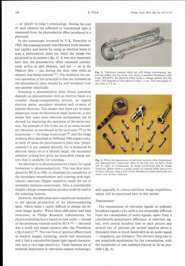
to the special peculiarities of the photoconductinglayer, which made it rather difficult to obtain the de-sired image quality. When these difficulties had beenovercome, at Philips Research Laboratories, forphotoconducting layers based on lead oxide - insteadof the antimony sulphide used by ReA [4] - the resultwas a small and simple camera tube, the Plumbicon(figs 2 and 3) [5]. Thiswas free of spurious effects (suchas shadow images, smearing, dazzle and saturation)and it had a reproducible linear light/signal character-istic and a very high sensitivity. These features are ofessential importance in television-camera technology,
K.TEER Philips Tech. Rev. 42, No.IO/11/12
Fig. 2. Television camera tubes are still being continuously im-proved today: this cut-away view shows a modern Plumbicon tube(type XQ4187). An electron beam scans a charge pattern (on theleft). The diagonal of this pattern is only 1.1 cm. The totallength ofthe tube is 7.8 cm.
Fig. 3. While the dimensions of television camera tubes diminished,the characteristics improved. Here in the top row we have, fromleft to right, an iconoscope, an image iconoscope and an imageorthicon. Below there is a great variety of camera tubes: first a rowof four vidicons, then a row of five Plumbicon tubes and finally an-other row of four vidicons.
and especially in colour-television image acquisition,which will be mentioned later in this article.
Transmission
The transmission of television signals as ordinarybroadcast signals or by cable is not essentially differentfrom the transmission of audio signals, apart from aconsiderable quantitative difference. A television sig-nal, with several hundred lines in each picture andseveral tens of pictures per second requires about athousand times as much bandwidth as an audio signal- megahertz, not kilohertz. The obvious thing was touse amplitude modulation for the transmission, withthe bandwidth of one sideband limited as far as pos-sible (fig. 4).

Philips Tech. Rev. 42, No. 10/11/12 TELEVISION TECHNOLOGY 299
In addition the principle of interlacing (fig. 5) wasintroduced, which reduces the bandwidth required bya factor of about 2. When this principle is applied the25 pictures (or frames) that are acquired and dis-played per second (in the European system) are trans-mitted in the form of 50 half-pictures or 'fields' , withalternate scans containing only the odd lines or onlythe even lines. The viewer is perceptual strongly in-clined to interpret two successive half-pictures of312~ lines (in the European system) as a complete pic-ture of 625 lines. Because of the interlacing the pictureflicker is reduced to an acceptable level to the viewer,although parasitic visual effects are not completelyabsent. The amount of information transmitted persecond is of course only a half compared with thesituation of 50 complete scans of the picture persecond.
Precisely because this intervention really gives theviewer less than his due, it is a rather frustratingthought that in another sense much more is trans-mitted than he really 'needs. This is because the picturecontent usually shows so many fragments that arestrongly correlated in place and time that there maywell seem to be frequent repetition of what has al-ready been transmitted and hence an unheard-ofwastage of transmission capacity.
Unfortunately it is not simple to improve the situa-tion by using a more efficient procedure, although adifference of a factor of 100 in the amount of infor-mation transmitted and actually required can be madeacceptable. The problem has received a lot of atten-tion through the years [61, and although more efficientmethods have been proposed they have not as yet ledto genuine applications.
The high bandwidth of video signals compels theuse of a correspondingly high carrier frequency(higher than 40 MHz) with the modulation. At thesefrequencies electromagnetic waves are propagated ina straight line in the Earth's atmosphere, so that atransmitter cannot reach much further than the hori-zon. This means that for a coverage area of any size alarge number of relay transmitters soon become neces-sary. Moreover, this means that for television thecompetitive position of cable compared with broad-casting is stronger than in radio.
Important qualitative differences between audioand video signals are the nature and the measure ofthe permissible distortion. For audio signals the fre-quency content ('the spectrum') is the first essential,for video it is the signal waveform.It was a while before anyone realized sufficiently
that the old touchstone for system quality, the fre-quency characteristic, ought to be traded in for the,step-function response [71, that nonlinearity could be
Q o 5MHz -f
/ ! \b o fo --.. f
o --.. f
Fig. 4. a) The frequency spectrum of a television signal extendsfrom zero to several megahertz. b) In the most well-known form ofamplitude modulation ('double-sideband modulation') of a carrierof frequency fo the bandwidth required is doubled. c) To managewith a smaller bandwidth, without requiring too complicated areceiver, one sideband of the television signal is fully transmittedand the other is oniy partially transmitted. A filter in the receiver infront of the actual detector converts this into a true 'vestigial-side-band-modulated' signal (chain-dotted line) [21.
1 . • ;----- __2 ...:::..... !3 ~ --- ,------ _
45 ----.:::....::.-----.:... .------6 ---___ ". ;7 ---~~-~------_ ___
---~~-:::~_t'~c_;_;::----- --r------:::.T; -,--------t----------~~
Fig. 5. In an interlaced scan all the odd lines (shown continuous)and then all the even lines (shown dashed) are scanned in turn. Thisgives two fields (or rasters), which combine to form one picture (orframe).
[1) J. van der Mark, An experimental television transmitter andreceiver, Philips Tech. Rev. 1, 16-21, 1936.
(2) F. Kerkhof and W. Werner, Television, Meu1enhoff, Amster-dam 1952;D. G. Fink (ed.), Television engineering handbook, McGraw-Hill, New York 1957.
(3) P. Schagen, H. Bruining and J. C. Francken, The image icono-scope, a camera tube for television, Philips Tech. Rev. 13,119-133, 1951/52.
(4) P. K. Weimer, S. V. Forgue and R. R. Goodrich, The vidicon- photoconductive camera tube, RCA Rev. 12,306-313,1951.
(5) E. F. de Haan, A. van der Drift and P. P. M. Schampers, The'Plumbicon' , a new television camera tube, Philips Tech. Rev.25, 133-151, 1963/64.
(6) K. Teer, Some investigations on redundancy and possible band-width compression in television transmission,Thesis, Delft1959. Also published in: Philips Res. Rep. 14, 501-556, 1959and 15, 30-96, 1960.
(7) J. Haantjes, Judging an amplifier by means of the transientcharacteristic, Philips Tech. Rev. 6, 193-201, 1941.

300
treated more tolerantly in video transmission and thatgroup delay needed much more careful attention.The transmitted video information only has any sig-
nificance for the viewer, of course, if the periodicityand phase of the image scan are in step at transmitterand receiver. For this reason signals also have to betransmitted to indicate the end of each line and eachpicture. This is done by adding easily detectable' syn-chronization' pulses to the video information. A con-stant reference level for the picture brightness (the'black level') is also transmitted to set the receiver sothat pixels at zero brightness do indeed radiate nolight (fig. 6).
Because of the enormous difference in the video andsound bandwidths, the television sound signals runthe danger of ending up in some neglected corner- but certainly not in an unnecessary corner, sincemuch picture material is completely incomprehensiblewithout the associated sound. The sound channel isgenerally provided by an extra frequency-modulatedcarrier at a fixed frequency spacing from the visioncarrier.
So far the number of lines has always been stated interms of a few hundred. Regular transmissions ofsuch signals, with 405 lines, started in the UnitedKingdom in 1936. In the United States, after manyexperiments with 343 and 441 lines, the official stan-dard was set at 525 lines in 1941. Only after WorldWar II was the number of lines settled in continentalEurope, where most countries had fallen in with theproposal of 625 lines. In France and in a few otherplaces, however, a standard of 819 lines had beenchosen [81. Regular television broadcasts started in theNetherlands in 1951.Colour television has brought about a somewhat
greater standardization in Europe in the sense thatwhen it was introduced the United Kingdom andFrance also went over to 625 lines.The choice of the picture frequency has so far led to
an obvious dichotomy, based on the frequency of theexisting electricity supply mains (30 pictures persecond in the United States and Japan, 25 pictures persecond in Europe).
Display
Just as in the acquisition of the image, in its displaythe mechanical solutions were soon replaced by elec-tronie ones with an electron beam and a luminescentscreen.The 'Braunsche Röhre' (later called a cathode-ray
tube, now usually a picture tube) had been knownsince 1897, but it required some improvement. Dimen-sions, shape, cathode, phosphors, electron optics, de-flection and high-voltage circuits: all were subjects for
K. TEER Philips Tech. Rev. 42, No. 10(11(12
study in their combined context. Only the very oldesttelevision tubes ('kinescopes') still contained the origi-nal green luminescent phosphor. This was very rapidlyreplaced by phosphor combinations that gave whitelight and had already been described in patents from
p p
..Jf\\1/
BI
\ IL
-tF L
Fig.6. In a television signal the actual picture information P is alter-nated with other important information. Between every two linesthere is a clear pulse L for line synchronization. The transition fromone field to the next is signalled by a fairly complicated pulse pat-tern F (the picture information is omitted here). The black level BIis briefly inserted between every two lines.
Fig. 7. Television receivers from the late thirties; left: console modelwith built-in radio; centre: console model for television only; right:table model.
Fig. 8. The electrical components of the receiver of fig. 7 (centre).The screen of the cathode-ray tube is shown on the left. At thecentre is a chassis with power-supply circuits (the 'high-tension sup-ply') and the timebase generators. At the top right - in the verticalplane - is the chassis with the amplifier stages for picture, soundand synchronization signals. Below this is the system of coils forfocusing and deflecting the electron beam in the cathode-ray tube.

Philips Tech. Rev. 42, No. 10/11/12 TELEVISION TECHNOLOGY 301
the early twenties. The usual screen dimension in 1936was 10 inches (figs 7 and 8). Philips were the first tobring in the 21-inch screen, in 1954.Nor has there been any lack of attempts to obtain
picture display by methods other than the picturetube. Much of the drive to obtain 'flatter' devicesarose because of the inconvenient dimension perpen-dicular to the screen - the length of the tube. Inrecent years a few versions in which a flatter construc-tion [91 has been obtained by folding the electronbeam (fig. 9) have appeared on the market. In addi-tion new possibilities for display panels of smallformat have been found on the basis of liquid-crystaltechnology [lOl.
A well-known extension of the potential applica-tions of the cathode-ray tube is optical projection,which in addition to larger dimensions can also pro-vide a different relation between picture size andcabinet depth (fig. 10). But as yet no real attack hasbeen made on the position occupied by the conven-tional direct-vision picture tube.
Fig. 9. A flat display tube developed by Philips, seen obliquely fromthe rear. The electron gun directs its beam downwards; the elec-trons are then deflected upwards round a metal screening plate andaccelerated towards the screen. The total thickness of the tube isless than 7.5 cm and the picture diagonal is about 30 cm. 1 metalcan; 2 line-deflection plates; 3 electron gun; 4 vacuum seal; 5 win-dow; 6 phosphor screen; 7 electron multiplier; 8 frame-deflectionplates; 9 electron beam; JO deflection lens.
[8J W. Werner, The different television standards, considered fromthe point of view of receiver design, Philips Tech. Rev. 16,195-200, 1954/55.In 1985 the international recommendations for television sys-tems with numbers of lines other than 525 or 625 were with-drawn. In practice this means the end of such systems.
[9J J. R. Mansell et al., The metal-dynode multiplier: a new com-ponent in CRT design, Displays 4, 135-139, 1983.
[IOJ T. S. Perry, Pocket TVs are inching ahead, IEEE Spectrum 22,No. 7 (July), 54, 1985;C. M Apt, Perfecting the picture, ibid., 60-66;S. Morozumi, K. Oguchi and H. Ohshima, Latest develop-ments in liquid crystal television displays, Opt. Eng. 23,241-246, 1984.
a
Fig.IO. Monochrome projection-television receiver dating from thelate forties. a) The projection screen is raised above the console,which contains the television projector and also a radio. The screencan be folded away into the console. b) A view of the interior: 1 op-tical unit; 2 beam-deflection unit; 3 high-voltage generator (25 kV);4 television receiver (picture and sound); 5 radio receiver; 6 recti-fier. (See also fig. 16.)
302
Extension of the possibilities
With the three basic functions described a televisionbroadcasting system can be set up that is suitable forthe provision of most forms of visual information.There are however two important extras that, whilenot absolutely necessary, have been found to be par-ticularly desirable. These are the recording of televi-sion signals and the addition of colour to the picture.The first serves to separate the instant at which a pic-ture manifests itself from the instant of transmissionor reception of that picture, so that there is a hugepotential increase in the picture information availablefor transfer via television. The second extra serves ofcourse to give a further and better approach to theimpression of reality.
First of all we shalliook at colour television, where,as in the foregoing, the triple basic problem of imageacquisition, transmission and display again confrontsus.
The measurement of colour information
The question of identification of a pixel by chrom-inance and luminance nu is described in colourtheory. There it is stated that practically all impres-sions of light can be obtained by the superposition ofthree well-chosen monochromatic component picturesin red, green and blue, and that a unique transforma-tion exists from any arbitrary light impression thatwe wish to characterize to this triple-monochromaticimitation.
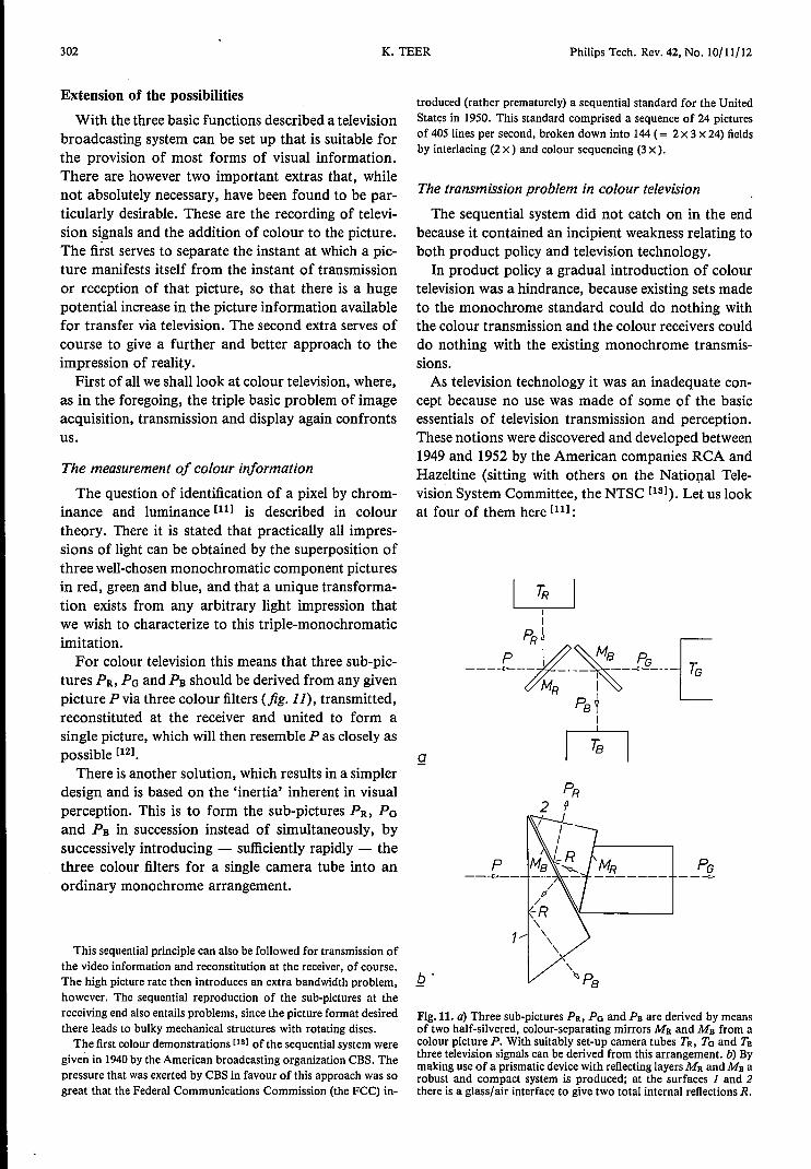
For colour television this means that three sub-pic-tures PR, Po and PB should be derived from any givenpicture P via three colour filters (jig. 11), transmitted,reconstituted at the receiver and united to form asingle picture, which will then resemble P as closely aspossible [121.
There is another solution, which results in a simplerdesign and is based on the 'inertia' inherent in visualperception. This is to form the sub-pictures PR, Poand PB in succession instead of simultaneously, bysuccessively introducing - sufficiently rapidly - thethree colour filters for a single camera tube into anordinary monochrome arrangement.
This sequential principle can also be followed for transmission ofthe video information and reconstitution at the receiver, of course.The high picture rate then introduces an extra bandwidth problem,however. The sequential reproduetion of the sub-pictures at thereceiving end also entails problems, since the picture format desiredthere leads to bulky mechanical structures with rotating discs.
The first colour demonstrations [13] of the sequential system weregiven in 1940by the American broadcasting organization CBS. Thepressure that was exerted by CBS in favour of this approach was sogreat that the Federal Communications Commission (the FCC) in-
K.TEER Philips Tech. Rev. 42, No. 10/11/12
troduced (rather prematurely) a sequential standard for the UnitedStates in 1950. This standard comprised a sequence of 24 picturesof 405 lines per second, broken down into 144 (= 2 x 3 x 24) fieldsby interlacing (2 x) and colour sequencing (3 x ).
The transmission problem in colour television
The sequential system did not catch on in the endbecause it contained an incipient weakness relating toboth product policy and television technology.
In product policy a gradual introduetion of colourtelevision was a hindrance, because existing sets madeto the monochrome standard could do nothing withthe colour transmission and the colour receivers coulddo nothing with the existing monochrome transmis-sions.As television technology it was an inadequate con-
cept because no use was made of some of the basicessentials of television transmission and perception.These notions were discovered and developed between1949 and 1952 by the American companies RCA andHazeltine (sitting with others on the National Tele-vision System Committee, the NTSC [131). Let us lookat four of them here [lll :
g
p
1
Fig. lt. a) Three sub-pictures PR, Po and Pe are derived by meansof two half-silvered, colour-separating mirrors MR and Ms from acolour picture P. With suitably set-up camera tubes TR, To and Tsthree television signals can be derived from this arrangement. b) Bymaking use of a prismatic device with reflecting layers MR and Ms arobust and compact system is produced; at the surfaces 1 and 2there is a glass/air interface to give two total internal reflections R.

Philips Tech. Rev. 42, No. 10/11/12 TELEVISION TECHNOLOGY 303
• In the first place there is the perceptual effect thatwith correct display of the luminance at standardsharpness, lower sharpness requirements can be setfor filling in the colour.• In the second place it was found that a high-fre-quency disturbance in the picture that occurs in op-posite phase in successive lines and pictures can betolerated to a high degree.• A third important fact is that the eye is much moresensitive to errors of hue (yellow or orange) thanto colour-saturation errors (bright yellow or lightyellow).• Fourthly, it was found that viewers object more toan incorrect colour than to a complete lack of colour.All this has led to a system in which the basic signal
is a luminance signal (similar in general terms to theconventional monochrome signal). Within the samebandwidth a subcarrier is added that has oppositephase in successive lines and pictures, and is modul-ated in quadrature by two colour-information signalsoflimited bandwidth (1 to 1.5 MHz); seefig.12. In thereceiver the colour information is recovered by syn-chronous detection because a suppressed carrier isused and because both amplitude and phase have tobe determined.
The luminance signal Y is obtained from a linear combination ofthe three component signals R, 0 and B corresponding to red, greenand blue (Y = aR +pO + yB). For modulating the chrominancesubcarrier two 'colour-difference signals' were used (Y - RandY - B), which indicate, when correctly normalized, how much eachpixel differs from a pure monochrome pixel.The form of modulation chosen leads in the first instance to a low
mean value of the subcarrier and in addition makes the amplitudemore or less proportional to the colour saturation (a monochromepicture corresponds to a carrier amplitude of zero), while the phaseis a measure of the hue.
Such a system was officially sanctioned in the UnitedStates under the name NTSe by the Fee in December1953, and the sequential system was abandoned; Japanalso chose the NTSe system. In Europe other systemswere adopted, which can be seen however as modifi-cations of the NTSe system: the SEeAM system inFrance (1958) and in the East-European countries,and the PAL system in the other countries [14][151.
Regular colour transmissions started in the UnitedStates in 1954, in Japan in 1960 and in Europe in 1967.
The display of colour pictures
The all-electronic compatible simultaneous-coloursystem described above requires simultaneous displayof the colour components, of course. The 'single-tubesolution' that was produced for this in 1950 was theshadow-mask tube from ReA, in which the three
colour components were presented next to one an-other for each pixel (fig. 13). A shadow mask just infront of the phosphor screen of the cathode-ray tubegives a pattern of dots as a shadow image of the scan-ning electron beam. The tube contains three electronguns so that three such dot patterns are formed on thephosphor screen. The phosphor surface is minutelydivided into red, green and blue phosphor dots,accurately positioned with respect to the three dotpatterns.
This idea - which has of course followed a longroad of improvement in reproducibility, stability ofalignment, format and tube shape - has so far re-mained the dominant one in colour television repro-duction. In 1971 the 26-inch screen with 110° deflec-tion was put on the market by Philips and ReA as animportant milestone in this development.
Naturally there were many attempts to find alter-natives during and after the long development of theshadow-mask principle. The index-tube principle [141
should just be mentioned here, since it was extensivelytested in laboratory versions and is applied, thoughonly on a very modest scale. Most important, it againillustrates the possible choice in colour television be-tween a simultaneous procedure and a sequential one.
Y I Q S/ / /
r- __L L \ r, r-.::I.::-.:=1
_f i \I \-1.25 -0.75
-1 0 13.58 4.5
2 3 4 5MHz- f-fo
Fig.12. Frequency spectrum of a colour television signal modulatedby the vestigial-sideband method in the NTSC system. All the fre-quencies are related to the carrier frequency /0, The colour infor-mation takes the form of two colour-difference signals I and Q thatmodulate a sub carrier at 3.58 MHz. (Q has a smaller bandwidththan I.) For completeness the position of the sound information Sin the spectrum is also shown: it has its own subcarrier at 4.5 MHz.
[11] F. W. de Vrijer, Fundamentals of colour television, PhilipsTech. Rev. 19,86-97, 1957/58.P. M. van Alphen, Applications of the interference of light inthin films, Philips Tech. Rev. 19, 59-67, 1957/58;H. de Lang and G. Bouwhuis, Colour separation in colour-television cameras, Philips Tech. Rev. 24, 263-271, 1962/63.D. G. Fink, Perspectives on television: the role played by thetwo NTSC's in preparing television service for the Americanpublic, Proc. IEEE 64, 1322-1331, 1976.J. Davidse, Transmission and decoding in colour television,Thesis, Eindhoven 1964. Also published in: Philips Res. Rep.19, 112-194 and 195-280, 1964.F. W. de Vrijer, Colour television transmission systems, PhilipsTech. Rev. 27, 33-45, 1966/67;D. H. Pritchard and J. J. Gibson, Worldwide color televisionstandards - similarities and differences, SMPTE J. 89,111-120, 1980.
[l2]
[lS]
[14]
[15]

304
a
K.TEER Philips Tech. Rev. 42, No.10/ll/12
bFig. 13. a) In a shadow-mask tube a colour television image is generated by the combined actionof three electron beams, a mask with a very large number of tiny holes and a picture tube coatedon the inside with accurately positioned red, green and blue phosphor dots. The electron beamsscan the entire screen 25 or 30 times a second under the controlof a number of deflection coils onthe neck of the tube. b) There is continuing refinement and improvement of the shadow-masktube: the aim is to make the screen as flat and rectangular as possible with the minimum overalltube length. The type 45AX 'flat square tube' shown here also has an extremely thin neck(29.1 mm); this means that less energy is required for the deflection of the electron beam.
In the index tube the principle used is essentiallypixel-sequential, Here again the pixels consist of threeadjacent red, green and blue segments, but now theseare excited by a single electron beam sequentially. Spe-cial measures are taken to link the actual target pointof the electron beam on the phosphor screen directlyto the modulation of the electron beam, so that thebeam can be rapidly modulated by the correct red,green and blue information. This type of picture tubeis available on the market for very small formats.
Recording television signals
In the late forties there was rapidly growing interestin recording audio signals on magnetic tape. Natur-ally enough, this prompted a search for comparableschemes for recording television signals. Film onlygave an unsatisfactory solution to the problem, and itwas not really compatible with electronics.
However, such ambitions ran into two problems:the very much larger bandwidth of television signalscompared with audio signals, and the much greaterimportance in television of the very low frequenciesand the d.c. component (the mean luminance orchrominance in a picture is essential information).Linear extrapolation of audio recording would require
colossal tape speeds, and with the conventionalmethods used in audio recording, which take no ac-count of frequencies from zero to about 50 Hz, thelow frequencies would be lost.
Elegant solutions were found for both problems.The high tape/head speed was obtained by usingrotating heads against a slowly moving tape, to scanthe tape in parallel tracks. The problem of the low fre-quencies was solved by using a form of frequencymodulation, which ensured optimum processing forthe vitally important low frequencies from the videosignal. Both principles were first applied by theAmpex company and demonstrated in 1956. Therotating-head principle was put into practice in ahead-wheel with four heads in a plane perpendicularto the direction of tape transport. The tape wascurved through 900 in the lateral direction to lieagainst the wheel. Some professional recording equip-ment is still made to this design today (fig. 14a).
For popular use in the home a cheaper mechanicalapproach had to be found. The answer was the helicalscan, in which the axis of the head-wheel is almost per-pendicular to the direction of tape transport (fig. 14b).The tape is wound round the head-wheel in a helixthrough 3600 or 1800, and the wheel has one head or

Philips Tech. Rev. 42, No. 10/11/12 TELEVISION TECHNOLOGY 305
two heads respectively. The 'dwell time' for onerotating head corresponds to a complete field scan.This principle was developed at Philips ResearchLaboratories in the fifties [161, and resulted in the firsthome video recorder (type EL 3400) in 1964, formonochrome signals only.It is also worth mentioning that the high frequencies
and the high tape/head speed that are at stake in videorecording set requirements for the write and readheads that are quite different from those of audiorecording. Drawing on their traditional expertise inmagnetic materials, Philips came up with a very ade-quate solution: the use of ferrite as a basic materialand glass as a filler material for the gap [171. This gavea wear-resistant, dimensionally constant material,which could handle the entire video spectrum.
New problems and answers
With the solution of all the basic problems like theones considered in the previous sections, televisiontechnology had grown to a definitive, adult and world-wide attainment. This did not mean, however, thattechnological ambition was less keen. Indeed, 'its verypersistenee meant that technical problems of a funda-mental nature were again encountered. Three prob-lems in particular made their presence felt: wideningthe dissemination of television, improving the picturequality and increasing the autonomy of the viewer inrelation to the video programme.
Before we go more deeply into these subjects, itshould perhaps be mentioned that the developmentsthat follow would be virtually inconceivable without
I
""I. ,\
~
-¥-- -1---- I I ~I II I \-~-- -\ .. _-• J' \ J track pa ttern
Fig.I4. a) The first practical method for recording television signalson magnetic tape made use of a rotating head-wheel whose axis isparallel to the direction of movement of the tape. The wheel con-tains four heads Hl-H4 that are used in turn. This produces a trackpattern almost at right angles to the length of the tape. l:J) In thehelical-scan recording method the track pattern is almost parallel tothe length of the tape. .
the transistor and the integrated circuit (the 'IC').However, since the entire history of electronics from1960 has been so universally and fundamentally de-cided by semiconductor technology, any further dis-cussion of this here would probably be inequitableand superfluous.
Widening the dissemination
The line-of-sight propagation at the carrier fre-quencies generally used by television transmittersrequires the highest possible location for the trans-mitting antennas to obtain the maximum coverage.Here, of course, space technology offers possibilitiesthat cannot be equalled by any terrestial antennamast [181.
The first use of terrestrial satellites for the transmis-sion of - stationary - images was in 1960 (via Echo,actually a simple reflecting balloon). The first trans-atlantic link for television signals with an 'active'satellite was obtained in the Telstar project in 1962-1963.The most elegant solution, however, was offered by
geostationary satellites, which stand still above theequator at a height of 36000 km (22500 miles) withrespect to any point on Earth. The first such satellitewas launched in 1963 in the SYNCOM project. Thesystematic use of geostationary satellites for inter-national telecommunication took shape in the found-ing of the Intelsat organization in 1965. More than100 countries are now members.All these examples relate to the use of satellites as
an intermediate link for further dissemination. Thedirect link between satellite and viewing population,now possible through the direct-broadcasting satellite(fig. 15), dates from 1984 [181.
We do not belittle the telecommunication engineerif we maintain that this development is fundamentallybased on contributions from space technology in pro-pulsion, launching, orbit control and attitude control.Their existence enabled a new form of communicationto come about without fundamental extensions toexisting telecommunication technology.The alternative to broadcasting, cable television,
also contains no technology of a fundamental naturethat requires special attention within the scope of thisarticle. An exception must however be made for therecent transition from electrical transmission to op-
[16) F. T. Backers and J. H. Wessels, An experimental apparatusfor recording television signals on magnetic tape, Philips Tech.Rev. 24, 81-83, 1962/63.
[17) S. Duinker, Durable high-resolution ferrite transducer headsemploying bonding glass spacers, Philips Res. Rep. 15,342-367,1960.
[18) W. L. Pritchard, The history and future of commercial satellitecommunications, IEEE Commun. Mag. 22, No. 5, 22-37,1984. '

306
tical transmission [19] in the cable network. Thearrival of the solid-state laser and the optical fibre areextremely important leaps in technological progress,in which the product of bandwidth and repeaterspacing has undergone a fundamental change. They
K.TEER Philips Tech. Rev. 42, No. 10/11/12
networks provides sufficient reason for mentioningthe subject here.
The first theoretical treatment of optical trans-mission was presented by K. C. Kao and G. A. Hock-ham [201 in 1966. In 1970 F. P. Kapron, D. B. Keek
Photograph: MBB-ERNO. Munich
Fig. 15. In the Franco-German TV-SAT/TDF-l project two geostationary satellites wil! belaunched shortly. They are intended for direct broadcasting of radio and television programmeson a frequency of about 12 GHz. A dish antenna with a cross-section of only 60 to 90 cm wil! givesatisfactory reception. The height of the satellite is 7 m and the width - including the deployedsolar panels - is about 20 m. The launch weight of the satellite is 2050 kg. The German satellite isto be launched first. It has five transmitting channels; four of them will be used. A single televisionsignalor a combination of 16 stereo-radio signals with 'compact-disc' quality can be transmittedon each channel. The transmitting and receiving zone for this German satellite are shown in thefigure.
have introduced a new era for digital transmissionand especially for the idea of integrating new andexisting communication services. The effect of this isnot so much a wider dissemination of television, but acompletely new place for this dissemination in thetotal pattern of technical communication. Althoughexperimental systems and operational long-distancelinks exist, there are as yet no operating networks car-rying a combination of speech, music, text, data andimage traffic for the public, but the prospect of such
and R. D. Maurer succeeded in producing an opticalfibre with an attenuation of less than 20 dB/km and inthe same year at the Bell laboratories continuousoperation of the semiconductor laser at room tem-perature was achieved [211.
A look back to that year 1970 makes us realize- with the present bandwidths in the GHz rangeand distances without amplifiers between 100 and200 km - what enormous progress has been attainedin optical fibres and lasers in a relatively short time.

Philips Tech. Rev. 42, No. 10/11/12 TELEVISION TECHNOLOGY 307
Towards higher picture quality
Television technology is in large measure based onthe peculiarities of our visual perception. By makingcontinuous pictures discrete in place and time, bylimiting the amount of data per unit area and per unittime, by accepting a minimum viewing distance andby tolerating parasitic effects with rapidly alternatingpolarity it was possible to remain within a certaintransmission-channel capacity and to complete thetransition from monochrome to colour televisionwithout making existing equipment unusable.
In the seventies the technical television world beganto wonder whether an improvement in the perceivedimages was perhaps desirable and how this might beachieved. A first parameter in the rather vague con-cept of 'picture quality' that came up for further con-sideration was the picture size. Since the introduetionof television the picture format had steadily increased,but had nevertheless reached a certain phase of stabil-ization at 26 inches, because price and weight seemedto preclude even larger dimensions. In the seventies,nevertheless, a further extrapolation received experi-mental attention. In addition, the principle of projec-tion television, in which difficulties bear a completelydifferent relationship to the increase in the picture size,was brought in once again (fig.16). When all the avail-able optical, electron-optical, electronic and phosphortechnology was put to work this concept gained con-siderably in strength. Modest numbers have now comeon to the market, some for home users.
Another aspect of picture quality is the presence orabsence of spurious visual effects (' artefacts'). Al-though it was maintained earlier that these effectswere not observable at a prescribed viewing distancebecause of visual tolerance, this is in general only ahalf-truth and for specific picture fragments it is quiteuntrue. (Everyone has seen this kind of effect in thecinema - in the classic example spoked wheels seemto rotate in the wrong direction.) Large-area flicker(especially with the European 25-Hz standard), linestructure, line crawl and interference patterns (cross-colour and cross-luminance) are indeed noticeable inspecial situations, certainly when the viewer has be-come acquainted with the quality of pictures in whichthese imperfections have been virtually eliminated.There are three different methods - not independentof one another - of trying to clean up the picture inthe broadcast system.
The first method is by linear extrapolation: greaterinformation transfer with more lines (for example1250 lines per picture,instead of 625) and better reso-lution per line.
The second method is the separation of signal com-ponents that interfere with one another by trans-
Fig. 16. Modern projection-television set. It contains three separate7-inch high-resolution cathode-ray tubes, which each reproduce asub-picture in one of the basic colours red, green and blue. Thethree sub-pictures are projected on the screen under electronic con-trol to give exact registration. The actual screen is rectangular andflat with a diagonal of 37 inches (about 94 cm). Below the screenthere is a drawer (shown open) containing various controls forvision and sound. The set can also be operated with remote control.
mittmg those components sequentially instead ofsimultaneously. In the MAC system (MultiplexedAnalog Components) with its many variations lumi-nance, chrominance and sound are transmitted in suc-cession, in synchronism with the line period [22]; seefig·17.
The third method is that of the ingenious processingof signals in the receiver, in which an apparently im-proved standard arises that has for example a quasi-heightened field frequency through the generation ofextra fields, or an increased number of lines becausethe information from successive field scans is addedtogether. The annoying interference effects can alsobe eliminated by combination of fields or lines since
[19] M. l. Schwartz, Optical fiber transmission - from conceptionto prominence in 20 years, IEEE Commun. Mag. 22, No. 5,38-48, 1984.
[20] K. C. Kao and G. A. Hockham, Dielectric-fibre surface wave-guides for optical frequencies, Proc. lEE 113, 1151-1158,1966.
[21] l. Hayashi, M. B. Panish, P. W. Fay and S. Sumski, Junctionlasers which operate continuously at room temperature, Appl.Phys. Lett. 17, 109-111, 1970.
[22] L. J. van de Polder, D. W. Parker and J. Roos, Evolution oftelevision receivers from analog to digital, Proc. IEEE 73,599-612, 1985.

308
these effects, as noted earlier, are deliberately alter-nated in polarity with fixed periodicities.The third method mainly relates to the provisions in
the receiver. The processing mentioned clearly impliesthe presence of signal memories that enable signalcomponents to be combined during a period of at leastone line period, or more usually during one or morefield periods. Such signal processing can in practiceonly be performed digitally. This makes the receiverin part a digital signal-processing machine [231.
The second method, sequential transmission, re-quires another transmitter, of course, and a com-pletely different receiver arrangement as well. This isbecause the time sequence in which the transmission ismade has to be restored to the original pattern again.The signals have to be made simultaneously availableby expansion of the time scale. This also requires pro-visions for storing signals temporarily, and readingthem out again in another time regime - and hence'digitization (or signal sampling, at the very least).Sequential transmission in the MAC system was firstproposed in Britain in 1981 [241.
The direct method of setting the standard at twicethe number of lines has been promulgated very insis-tently by Japanese institutions, NHK in particular,since the early seventies. Here, however, no kind ofcompatibility whatsoever with existing practice can beidentified. Moreover, the quadrupling of the band-width required causes great problems with the elec-tronies and the transmission methods. It makes the
Fig. 17. Picture obtained when a 'MAC' signal is reproduced with-out special decoding, as if it was an ordinary television signal. Inevery line period a small part is first used to transmit the colour in-formation, and the rest is used for the luminance information.Since there are two colour-difference signals (V and V), V-informa-tion and V-information alternate from line to line. A colour pictureof very high quality can be obtained with a MAC decoder, becauseall the various undesirable interactions between colour and lumi-nance information are intrinsically avoided with this system. (Theline-flyback periods are used for sound transmission; this is notvisible here, of course.)
K.TEER Philips Tech. Rev. 42, No. 10/11/12
demand for ways of reducing bandwidth particularlytopical. As has been argued previously, 'natural' pic-tures contain sufficient correlation for bandwidthreduction to be supported by arguments from infor-mation theory. However, the difficult fact remainsthat solutions of that type do again lead in the direc-tion of concessions to (new) vision-deceptive phenom-ena. Furthermore, the processing required is of such acornplexity that the usual reassurance that the price ofthe electronics is bound to fall provides insufficientbasis for confidence.
Television programme under viewer control
The video recorder was developed in the earlyseventies into a mechanical equipment that permittedthe use of cassettes. This video cassette recorder wasfirst put on the market by Philips in 1972 as the VCRsystem, to be followed later by the V2000 system. Theenormous advances that the video cassette recorderhas made since the late seventies received much oftheir impetus from the Sony and Matsushita com-panies, who reduced the tape usage so much that acomplete film could be recorded without a break on acassette. Besides the possibility of shifting broadcasttelevision programmes in time, the video cassette re-corder naturally offered from the start the possibilityof prerecorded cassettes (with programmes selectedand purchased by the viewer).The video cassette, the analogue of the audio cas-
sette, found a competitor in 1972 - the video disc(fig. 18), the analogue of the gramophone record.While no further fundamental technologies can benamed in relation to the video cassette recorder, atleast three significant technical measures used in thevideo-disc system should be mentioned [251. In the firstplace there is the application of geometrical structuresof similar dimensions to the wavelength of light as thecarrier of the information to be detected optically. Inthe second place there is the application of the laser inlarge-volume consumer electronics and in the thirdplace there is the accurate following of the informa-tion track by dual imaging of the information-readinglight ray within the same optical system. This is usednot only as the read optics but also as the alignmentoptics.
When the video disc was launched as a commercialproduct in the mid-seventies there were two versions:one with a mechanical 'pickup' - rather like an extra-polation of the traditional gramophone record (RCA,JVC) - and the other with the optical readout men-tioned above (Philips). Philips were the first in thefield (1976). As yet the video disc has obtained a lessfirm footing in the home than the video cassette. Theoptical version, however, is making steady progress

Philips Tech. Rev. 42, No. 10/11/12 TELEVISION TECHNOLOGY 309
Fig. 18. The information on the LaserVision disc is read out withthe aid of a light beam (shown red here) originating from a laser(horizontal cylinder, half-hidden below the disc). A system of lensesand moveable mirrors focuses the light beam on to the disc, whereit is reflected to a greater or lesser degree. The reflected light thentravels the same path in the reverse direction and arrives at a photo-sensitive detector (left foreground). This provides an electrical sig-nal suitable for further processing.
III professional applications for education and in-struction.The freedom of the television viewer only becomes
complete when he not only has effective autonomyover the pattern of the broadcast programmes andcan procure programmes of his own choice, but canalso produce his own programme material: the videocamera plus portable recorder enables him to do this.For a good design two quite separate kinds of tech-nical achievement are necessary: miniaturization ofthe video cassette recorder and miniaturization of thetelevision camera, so that they can be combined tomake a single unit of the same size as an amateur filmcamera (the 'camcorder').A great deal could be said about the miniaturization
of the recorder, but only little of a truly fundamentalnature. The miniaturization of the television cameraproceeds via two notable stages. The first is the re-placement of the bulky 'three-tube' arrangement- used for many years in studio cameras - by asingle tube [261; seefig.19. This can be done by makingdo with a sequential succession of pixels measuredseparately for red, green and blue. A fine transparentcoloured strip filter mounted on the light-sensitivesurface of the single camera tube can achieve this. Inessence this pixel-sequential approach is the conversesituation to the index tube mentioned earlier, and asin that case the great thing is to detect at any preciseinstant which of the three basic colours the scan isworking on. This problem can be solved by carefulmeasurement of the cyclic components in the outputsignalof the tube, referenced to the deflection of thescanning electron beam. There are a number of sophis-ticated methods for this; for example the colour strips
for the different basic colours can be applied at dif-ferent spacings, and therefore at different spatial 'fre-quencies' .
The second important stage in the miniaturizationof the camera is the replacement of the camera tubeby an 'image sensor' [271 [281; seefig. 20. An image sen-sor is a photosensitive integrated circuit of some tensof square millimetres containing an array of manyseparate photoconducting elements. These are inter-connected in such a way that the information aboutthe illumination of each can be transferred to the edgeof the chip via the other elements. This charge-transferprinciple had been proposed long before, in the mid-sixties, in the operation of the bucket-brigade delayline [291 (Philips, 1965) and of the charge-coupled de-vice [301 (Bell, 1970). The transfer in the image sensortakes place periodically and in relatively very shorttime intervals (5-500 I1S). This transfer puts the infor-
Fig. 19. Single-tube video camera for amateur use.
[231 M. J. J. C. Annegarn, A. H. H. J. Nillesen and J. G. Raven,Digital signal processing in television receivers, Philips Tech.Rev. 42, 183-200, 1986.
[241 K. Lucas and M. D. Windram, Direct television broadcasts bysatellite: desirability of a new transmission standard, IBAreport 116/81, Independent Broadcasting Authority, Winches-ter 1981.
[251 See for example the articles on these subjects that were pub-lished in Philips Tech. Rev. 33,177-193, 1973.
[261 P. K. Weimer et al., A developmental tricolor vidicon having amultiple-electrode target, IRE Trans. ED-7, 147-153,1960.
[271 H. Heyns, H. L. Peek and J. G. van Santen, Image sensor withresistive electrodes, Philips Tech. Rev. 37, 303-311, 1977.
[281 A. J. P. Theuwissen and C. H. L. Weijtens, The accordionimager, a new solid-state image sensor, to be published inPhilips Tech. Rev. 43, 1-8, 1986 (preprint available).
[291 F. L. J. Sangster and K. Teer, Bucket-brigade electronics - newpossibilities for delay, time-axis conversion and scanning,IEEE J. SC-4, 131-136, 1969.
[301 W. S. Boyle and G. E. Smith, Charge coupled semiconductordevices, Bell Syst. Tech. J. 49, 587-593, 1970.

310
Fig. 20. A comparison of an image iconoscope with a modern semi-conductor image sensor gives a good impression of the dramaticreduction in size in 50 years of television-camera technology.
mation from the pixels temporarily into a memorythat is read out later in such a way that the visualinformation appears in the correct sequence and atthe correct rate. This memory is in fact a second inte-grated circuit, which is combined with the photosen-sitive sensor on a single chip.The question of three sensor devices or one for
colour detection is just the same here as in the cameratube, of course. For the 'home camera' a single sensordevice with a colour-strip filter is used (at present with600 pixels per line [31l).
It is immediately obvious that the image sensortakes up far less space than the camera tube. The prin-ciple was first proposed at Philips (in 1966) [32l. Thefirst operating sensor dates from 1971. The devicesfirst came on the market a few years later. Cameraswith image sensor for amateur use appeared in theearly eighties. The 'camcorder' combination withimage sensor in one unit has recently become commer-cially available.
Television technology in another role
After this three-part review of the leading technicalproblems encountered in television, it is time for afinal word about television technology in another role.Traditionally television presents instruction and
amusement taken from 'natural' material. Since thelate sixties, however, television broadcasting and thetelevision set have started to be used as a graphicinformation system. The words 'teletext', 'viewdata'
K.TEER Philips Tech. Rev. 42, No. 10/11/12
and 'home computer' are key words in this context. Inrelation to television technology the home computerhas very few new fundamental aspects, and on theother hand it is still at such an early stage of use thatfurther discussion here is inappropriate. A brief wordshould however be said about teletext [22l, since itdepends on an addition to the existing system - infact a relatively small modification to the now clas-sical television signal and television receiver. The sys-tem was originally proposed and developed by Britishresearchers.
The dead times that arise in the scan during the fly-back from the bottom right of the picture to the topleft are used in teletext for transmitting coded lines ofgraphic information. This information is added to thetelevision signal proper at the transmitting end at thecorrect instants. Adding together the lines of codedinformation from' a number of fields (typically 12)produces reading matter that occupies one entire pic-ture (one 'page'), see fig. 21. A certain number ofpages (often several hundred) are transmitted in sue-cession in a continuously repeated sequence. At thereceiver a command can be given to select one pagefrom this sequence. The corresponding information isthen identified, separated from the television signalproper, collected in a memory that can contain theinformation for one page and decoded into a readablepicture of 24 lines of 40 characters. There is a waitingtime that depends on the position of the page in thesequence at the instant of command and on the lengthof the sequence. The average waiting time is 12seconds for every 100 pages in the sequences. Addingto the receiver an electronic memory that can containall the pages simultaneously will obviously eliminatethe waiting time.
In another graphic information system, viewdata(or in general, videotex [22l), a telephone connectionand a television receiver are used. The characters fromwhich the pictures are composed are generated in cir-cuits much like those found in teletext, but otherwisethis system has little resemblance to conventional tele-vision technology. Text can obviously be sent in bothdirections on the telephone line and can be imaged onthe television screen with the aid of a page-sized elec-tronie memory. The bandwidth of a telephone line isconsiderably less than that of a television transmitter,so that the information transfer takes place muchmore slowly (one page takes 4 seconds). On the other
[31] M. J. H. van de Steeg et al., A frame-transfer CCD colorimager with vertical antiblooming, IEEE Trans. ED-32,1430-1438, 1985.
[32] Dutch patent application No. 6805706, 23rd April 1968 andthe corresponding United States patent No. 3621283, appliedfor on 17th April 1969 (inventors: K. Teer and F. L. J.Sangster).

Philips Tech. Rev. 42, No. 10/11/12 TELEVISION TECHNOLOGY 311
Fig. 21. Two random examples of teletext pages. Simple diagrams can be shown as well as writteninformation.
hand the user can send signals himself and can there-fore reach the page file himself, so that his selectionprocess is free from the cyclical presentation of tele-text with the associated waiting time and limited con-tent.
As we noted, home computers, teletext and video-tex are the precursors of a kind of use of televisiontechnology that departs from the original intentions.An intrinsic feature here is the action of the viewer.As compared with the classic television situation, heoriginates more initiatives, intentions and impulses toobtain information in a more personal and business-oriented approach. In doing so he comes into greatercontact with the system, not only literally, but men-tally as well. This means that the man/machine inter-face is of growing importance - a concept that has
many aspects that we still know very little about. Soonce again we seem to stand at the start of an era, cer-tain only of surprises, blessings and disappointments.
Summary. A retrospective look at the growth of television technol-ogy shows a number of successive phases, rather like ever-growingconcentric circles. The first phase was that of the elementary prob-lems of image acquisition, transmission, and display in mono-chrome. In the second phase these problems recurred, but now forcolour pictures, and the idea of recording television signals alsoarose. In the next phase the central features were an extension ofthe methods of distribution (including the use of satellites), im-provement in the picture quality and individual control of theacquisition and recording of video signals. Finally, television can beseen as a constituent element in a number of applications (teletext,videotex, home computer) that would have been inconceivable inthe early days. This article gives a general picture of the develop-ments in television in the last fifty years. The accent is strongly onthe first stages in the evolution of the technology - invention andfeasibility model.