1 surfaces of materials surface modification techniques u785 introduction to nanotechnology spring...
Post on 21-Dec-2015
216 views
TRANSCRIPT
1
Surfaces of materialsSurface Modification Techniques
U785 Introduction to Nanotechnology
Spring 2003
Lecture 3
2
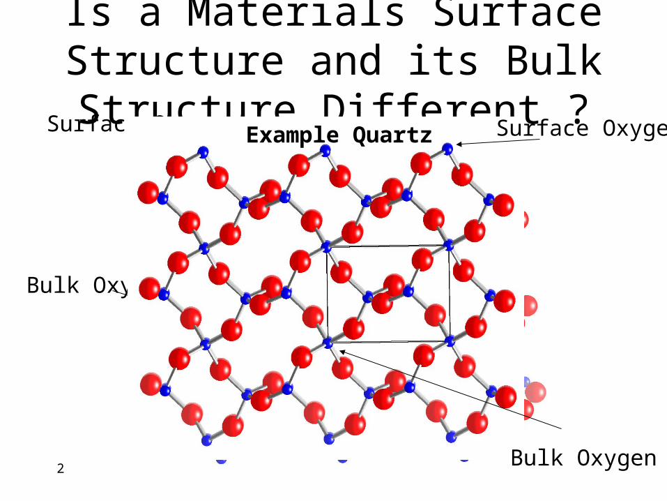
Is a Materials Surface Structure and its Bulk Structure Different ?
Surface Oxygen
Bulk Oxygen
Surface Oxygen
Bulk Oxygen
Example Quartz
3
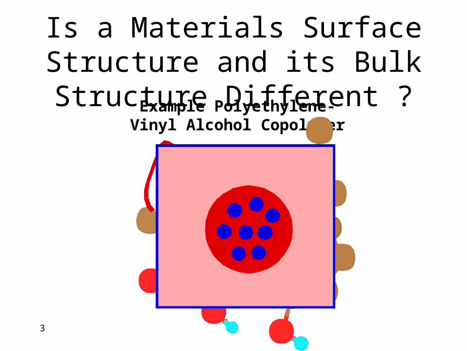
Is a Materials Surface Structure and its Bulk Structure Different ?
Example Polyethylene-Vinyl Alcohol Copolymer
4
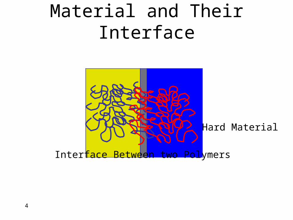
Hard Material
Material and Their Interface
Interface Between two Polymers
5
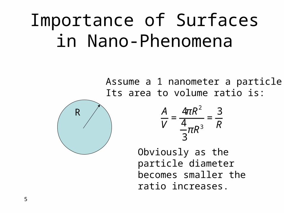
Importance of Surfaces in Nano-Phenomena
Assume a 1 nanometer a particle.Its area to volume ratio is:
€
AV
=4πR2
4
3πR3
=3R
Obviously as the particle diameter becomes smaller the ratio increases.
R
6
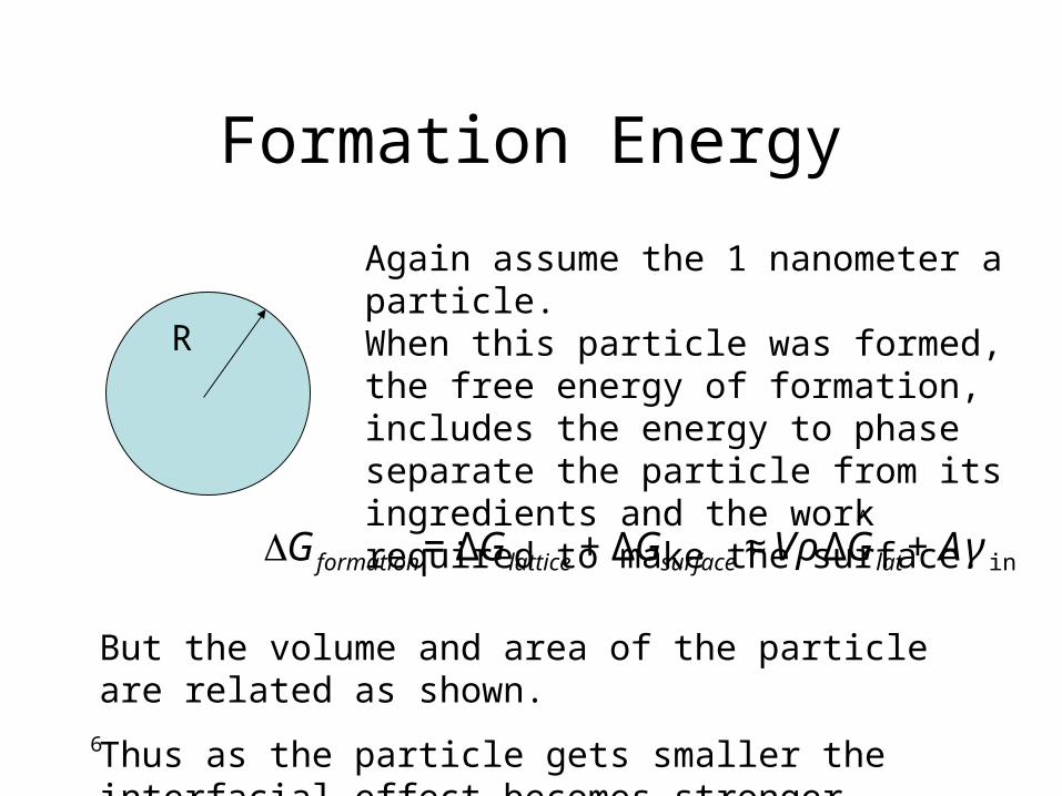
Formation Energy
Again assume the 1 nanometer a particle.When this particle was formed, the free energy of formation, includes the energy to phase separate the particle from its ingredients and the work required to make the surface.
R
€
ΔGformation = ΔGlattice + ΔGsurface ≈ VρΔGlat∧
+ Aγ int
But the volume and area of the particle are related as shown.
Thus as the particle gets smaller the interfacial effect becomes stronger
7
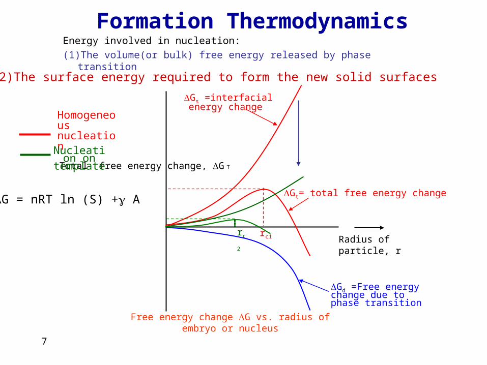
Formation ThermodynamicsEnergy involved in nucleation:
(1)The volume(or bulk) free energy released by phase transition
Free energy change ΔG vs. radius of embryo or nucleus
Radius of particle, r
Total free energy change, ΔG T
ΔGs =interfacial energy change
ΔGt= total free energy change
ΔGd =Free energy change due to phase transition
rc1rc2
Homogeneous nucleation
Nucleation on template
ΔG = nRT ln (S) + A
(2)The surface energy required to form the new solid surfaces
8
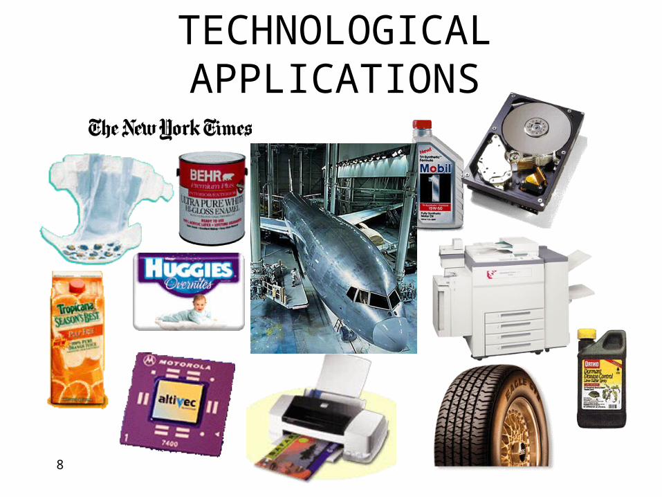
TECHNOLOGICAL APPLICATIONS
9
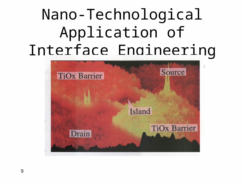
Nano-Technological Application of Interface Engineering
10
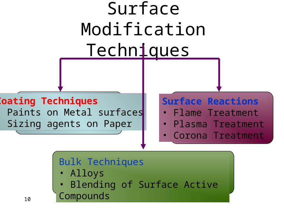
Surface Modification Techniques
Surface Reactions• Flame Treatment• Plasma Treatment• Corona Treatment
Coating Techniques• Paints on Metal surfaces• Sizing agents on Paper
Bulk Techniques• Alloys• Blending of Surface Active Compounds
11
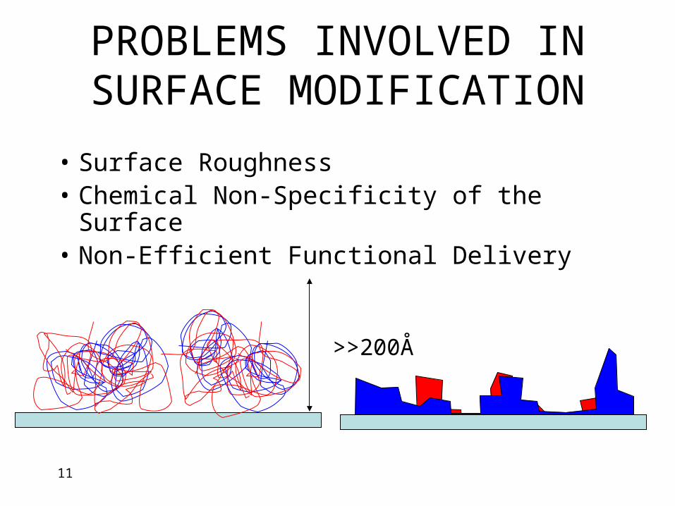
>>200Å
PROBLEMS INVOLVED IN SURFACE MODIFICATION
• Surface Roughness• Chemical Non-Specificity of the Surface• Non-Efficient Functional Delivery
12
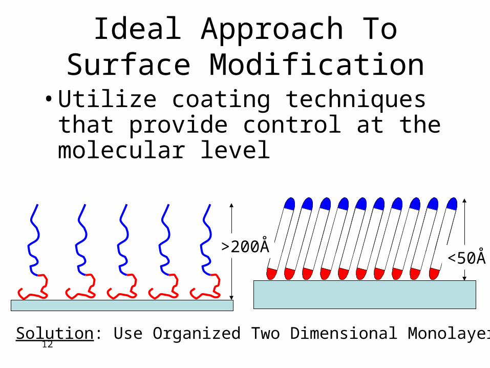
Ideal Approach To Surface Modification
Solution: Use Organized Two Dimensional Monolayers
>200Å<50Å
• Utilize coating techniques that provide control at the molecular level
13
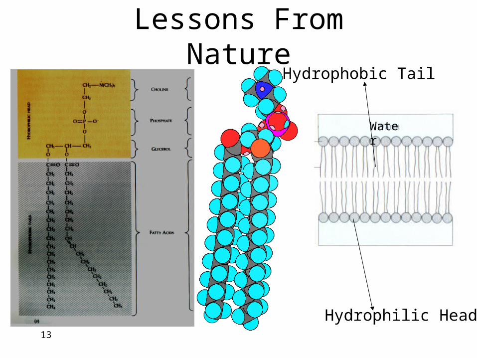
Lessons From Nature
Hydrophilic Head
Hydrophobic Tail
Water
14
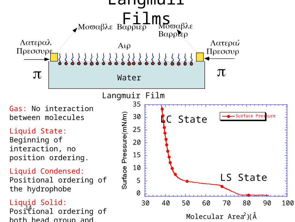
Langmuir Films
Water
Langmuir Film
π π
LateralPressure
LateralPressure
Air
Movable Barrier MovableBarrier
0
5
10
15
20
25
30
35
30 40 50 60 70 80 90 100
Surface Pressure
Molecular Area (Å 2)
LC State
LS State
Gas: No interaction between molecules
Liquid State: Beginning of interaction, no position ordering.
Liquid Condensed: Positional ordering of the hydrophobe
Liquid Solid: Positional ordering of both head group and hydrophobe
15
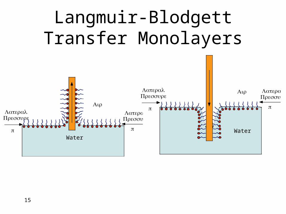
Langmuir-Blodgett Transfer Monolayers
Water
π π
LateralPressure
LateralPressure
Air
Waterπ π
LateralPressure
LateralPressure
Air
16
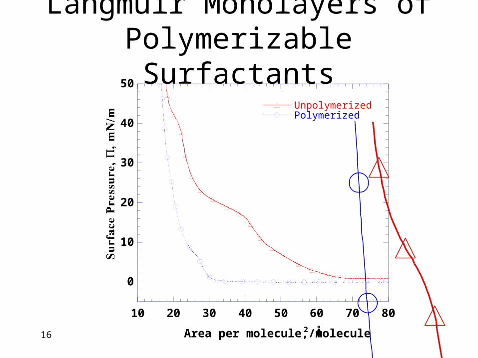
Langmuir Monolayers of Polymerizable Surfactants
0
10
20
30
40
50
10 20 30 40 50 60 70 80
UnpolymerizedPolymerized
Area per molecule, Å 2/molecule
Surface Pressure,
Π
, /mN m
17
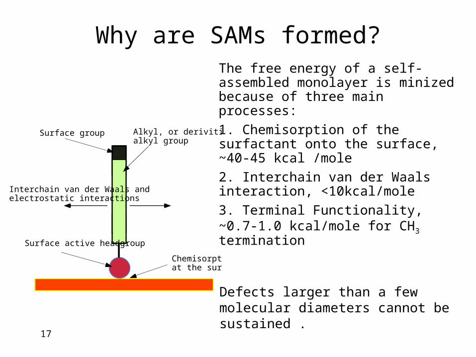
Why are SAMs formed?
The free energy of a self-assembled monolayer is minized because of three main processes:
1. Chemisorption of the surfactant onto the surface, ~40-45 kcal /mole
2. Interchain van der Waals interaction, <10kcal/mole
3. Terminal Functionality, ~0.7-1.0 kcal/mole for CH3 termination
Defects larger than a few molecular diameters cannot be sustained .
Chemisorptionat the surface
Alkyl, or derivitizedalkyl group
Surface group
Interchain van der Waals andelectrostatic interactions
Surface active headgroup
18
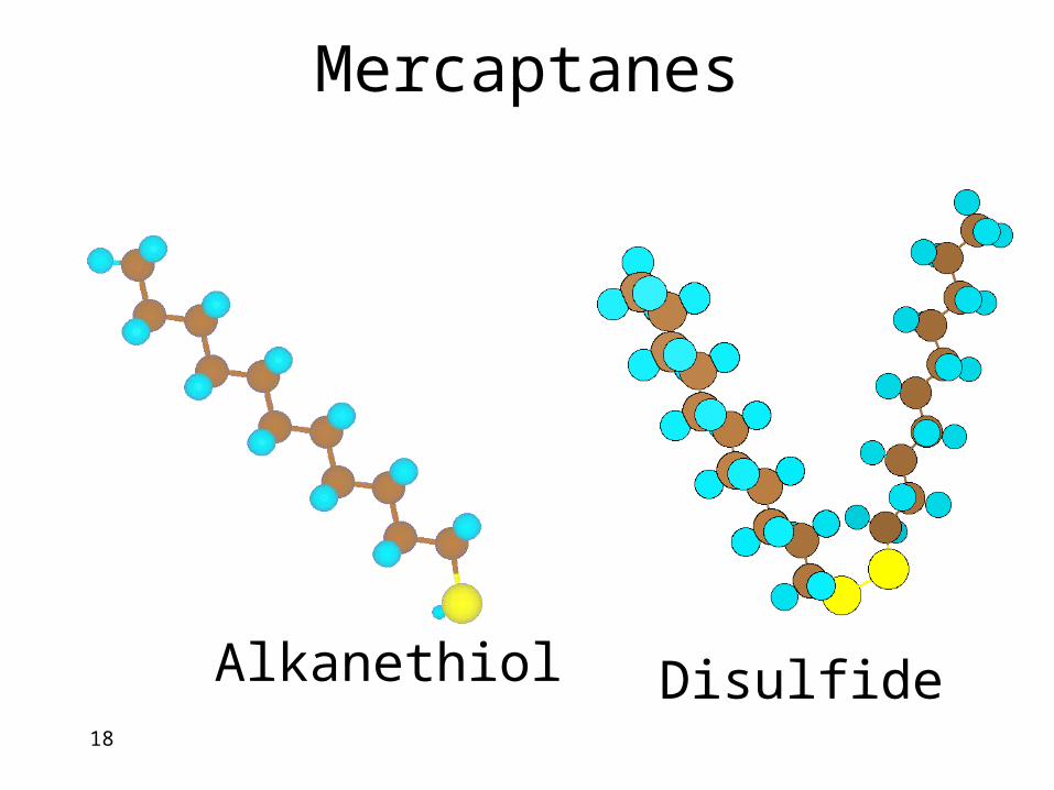
Mercaptanes
Alkanethiol Disulfide
19
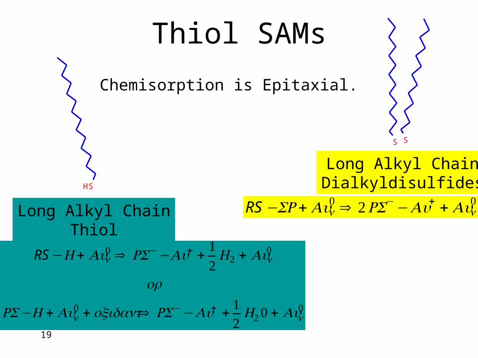
Thiol SAMs
S
H
Long Alkyl ChainThiol
Long Alkyl ChainDialkyldisulfides
S
S
RS −SR+Aun0 ⇒ 2RS−−Au+ +Aun
0
RS−H + Aun0 ⇒ RS−−Au+ +
12
H2 + Aun0
or
RS−H +Aun0 + oxidant⇒ RS−−Au+ + 1
2H20 + Aun
0
Chemisorption is Epitaxial.
20
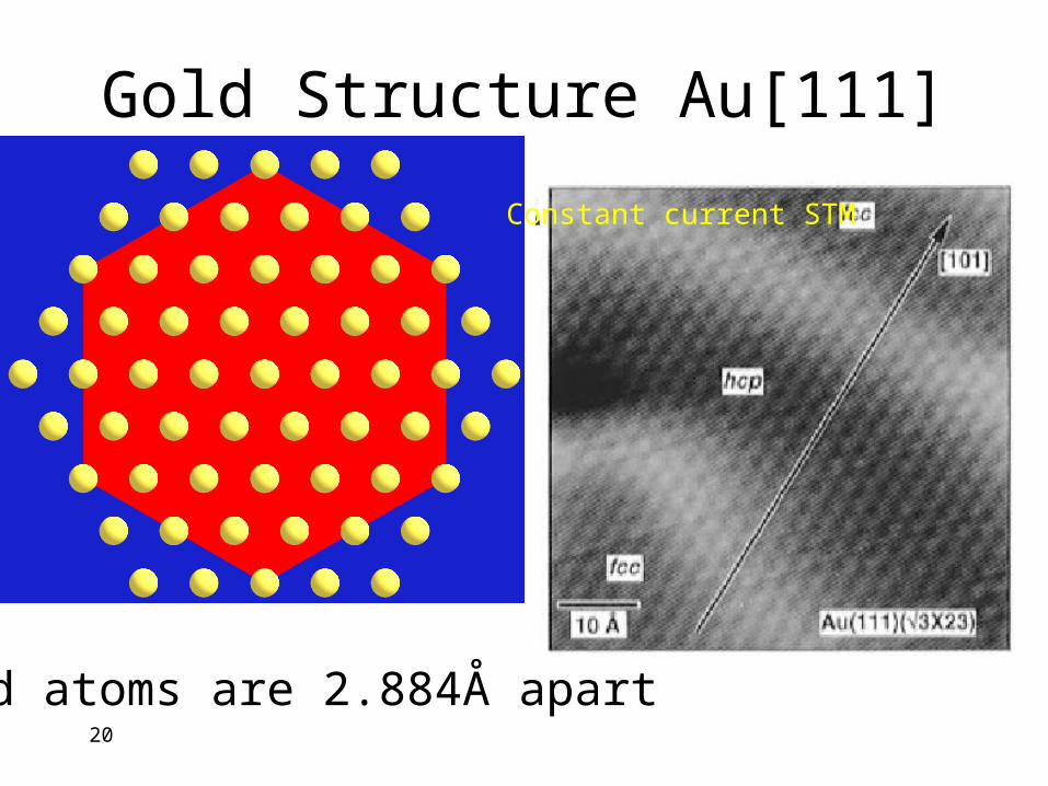
Gold Structure Au[111]
Gold atoms are 2.884Å apartx
y
z
Constant current STM
21
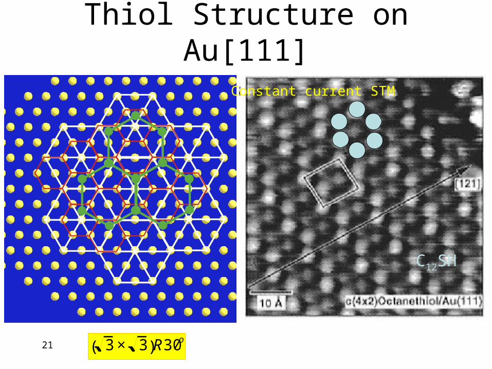
Thiol Structure on Au[111]
3× 3( )R30o
Constant current STM
C12SH
22
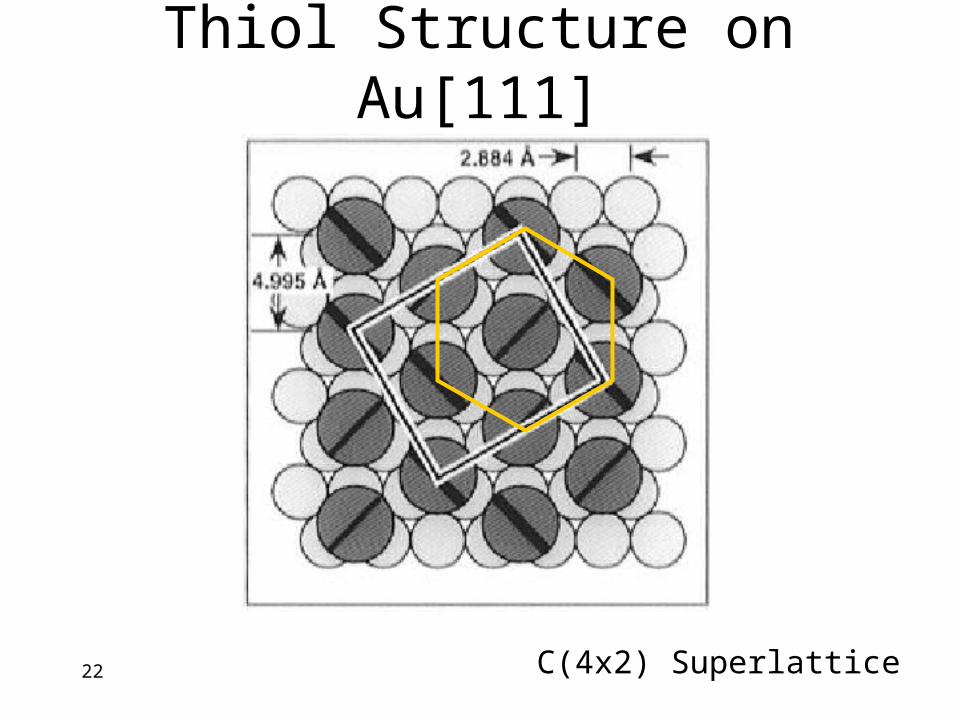
Thiol Structure on Au[111]
C(4x2) Superlattice
23
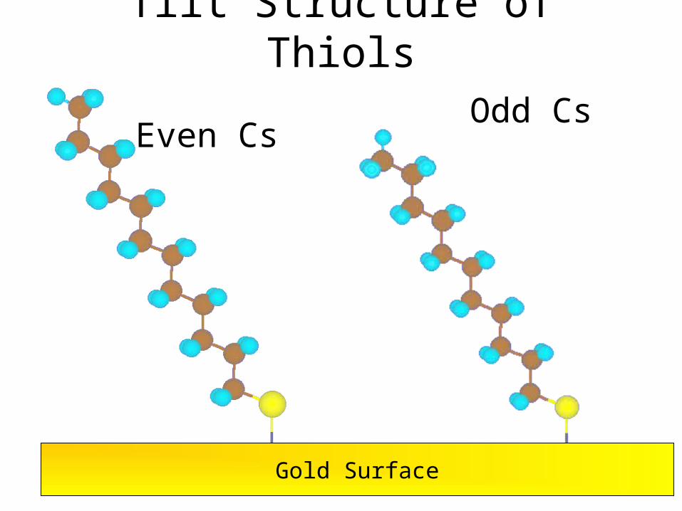
Tilt Structure of Thiols
Gold Surface
Even CsOdd Cs
24
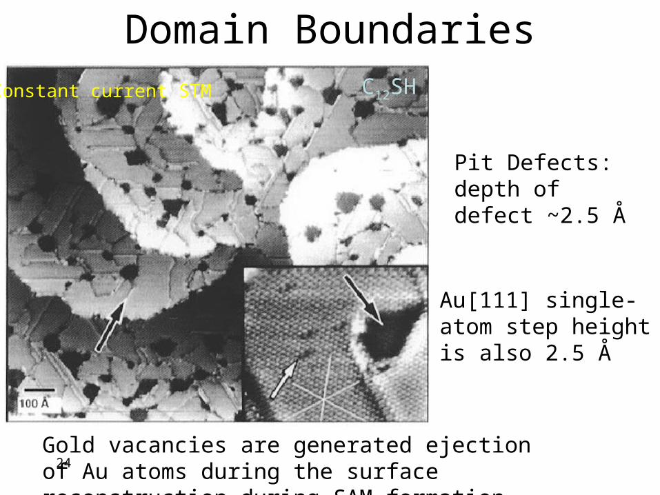
Domain Boundaries
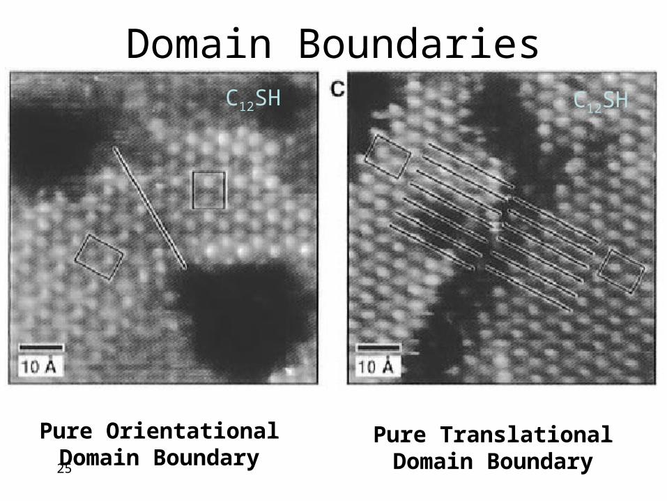
Pit Defects: depth of defect ~2.5 Å
Au[111] single-atom step height is also 2.5 Å
Gold vacancies are generated ejection of Au atoms during the surface reconstruction during SAM formation
Constant current STM C12SH
25
Domain Boundaries
Pure Orientational Domain Boundary
Pure Translational Domain Boundary
C12SHC12SH
26
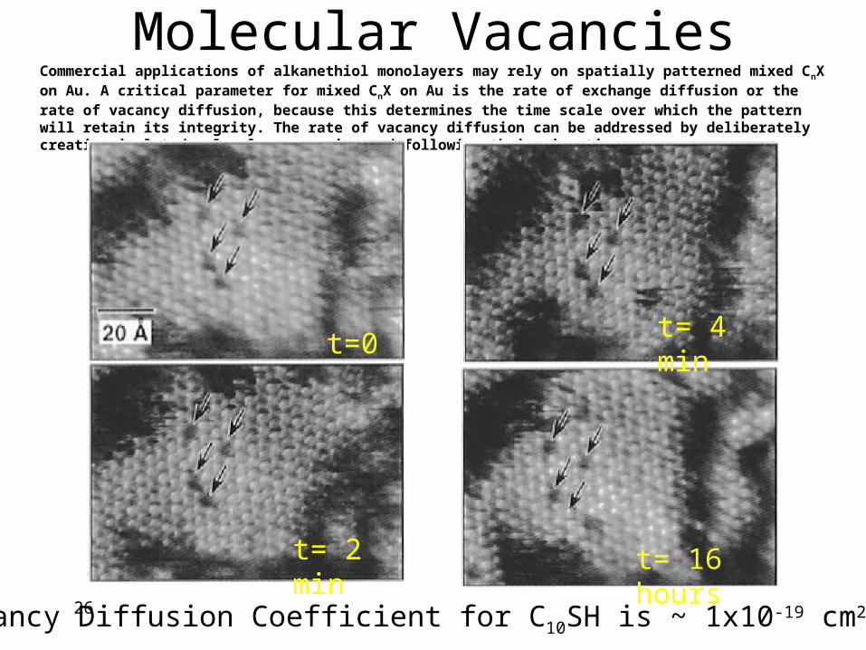
Molecular VacanciesCommercial applications of alkanethiol monolayers may rely on spatially patterned mixed CnX on Au. A critical parameter for mixed CnX on Au is the rate of exchange diffusion or the rate of vacancy diffusion, because this determines the time scale over which the pattern will retain its integrity. The rate of vacancy diffusion can be addressed by deliberately creating isolated molecular vacancies and following their migration.
t=0
t= 2 min
t= 4 min
t= 16 hours
Vacancy Diffusion Coefficient for C10SH is ~ 1x10-19 cm2/s
27
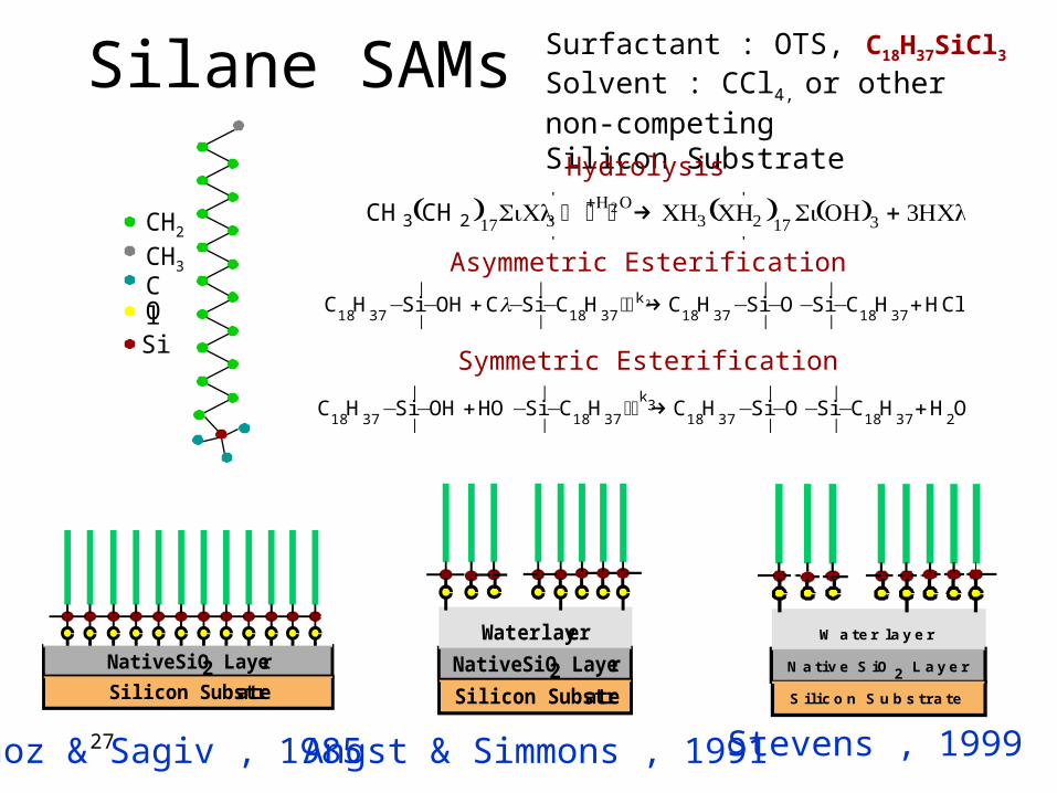
Silane SAMs Surfactant : OTS, C18H37SiCl3
Solvent : CCl4, or other non-competingSilicon Substrate
Angst & Simmons , 1991Maoz & Sagiv , 1985
CH2
CH3
Si
ClO
C18
H37
Si|
|Cl H
2O k C
18H
37Si
|
|OH HCl1− − + − − +⏐ →⏐
C H Si OH HO Si C H C H Si O Si C H H O18 37 |
|
|
|
18 37
k3
18 37 |
|
|
|
18 37 2− − + − − ⏐ →⏐ − − − − +
C H Si OH C Si C H C H Si O Si C H HCl18 37 |
|
|
|
18 37k
18 37 |
|
|
|
18 372− − + − − ⏐ →⏐ − − − − +l
Hydrolysis
Asymmetric Esterification
Symmetric Esterification
Water layer
Native SiO2 Layer
Silicon Substrate
Native SiO2 Layer
Silicon Substrate
W a t e r l a y e r
N a t i v e S i O 2 L a y e r
S i l i c o n S u b s t r a t e
Stevens , 1999
CH3 CH 2( )17SiCl3+H2O⏐ → ⏐ ⏐ CH3 CH2( )17 Si OH( )3 + 3HCl
28
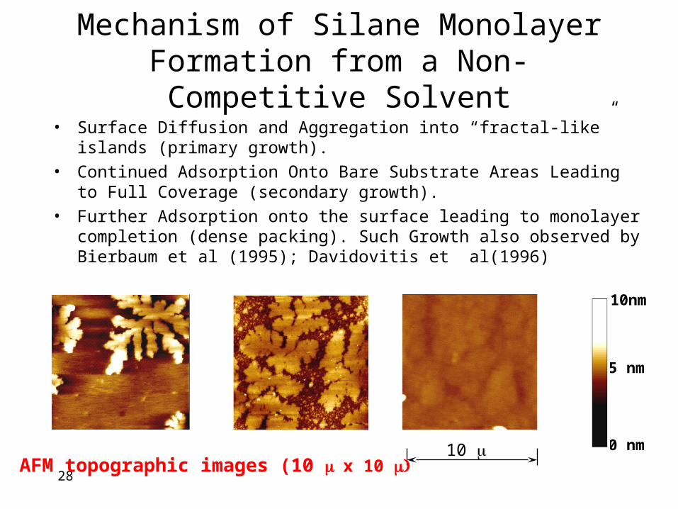
Mechanism of Silane Monolayer Formation from a Non-Competitive Solvent
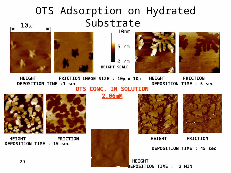
• Surface Diffusion and Aggregation into “fractal-like” islands (primary growth).
• Continued Adsorption Onto Bare Substrate Areas Leading to Full Coverage (secondary growth).
• Further Adsorption onto the surface leading to monolayer completion (dense packing). Such Growth also observed by Bierbaum et al (1995); Davidovitis et al(1996)
0 nm
5 nm
10nm
10 AFM topographic images (10 x 10
29
DEPOSITION TIME :1 sec
DEPOSITION TIME : 15 secDEPOSITION TIME : 45 sec
DEPOSITION TIME : 5 sec
DEPOSITION TIME : 2 MIN
HEIGHT FRICTION HEIGHT
HEIGHT
HEIGHT
HEIGHT
FRICTION
FRICTIONFRICTION
OTS Adsorption on Hydrated Substrate
IMAGE SIZE : 10 x 10
HEIGHT SCALE
OTS CONC. IN SOLUTION2.06mM
10
0 nm
5 nm
10nm
30
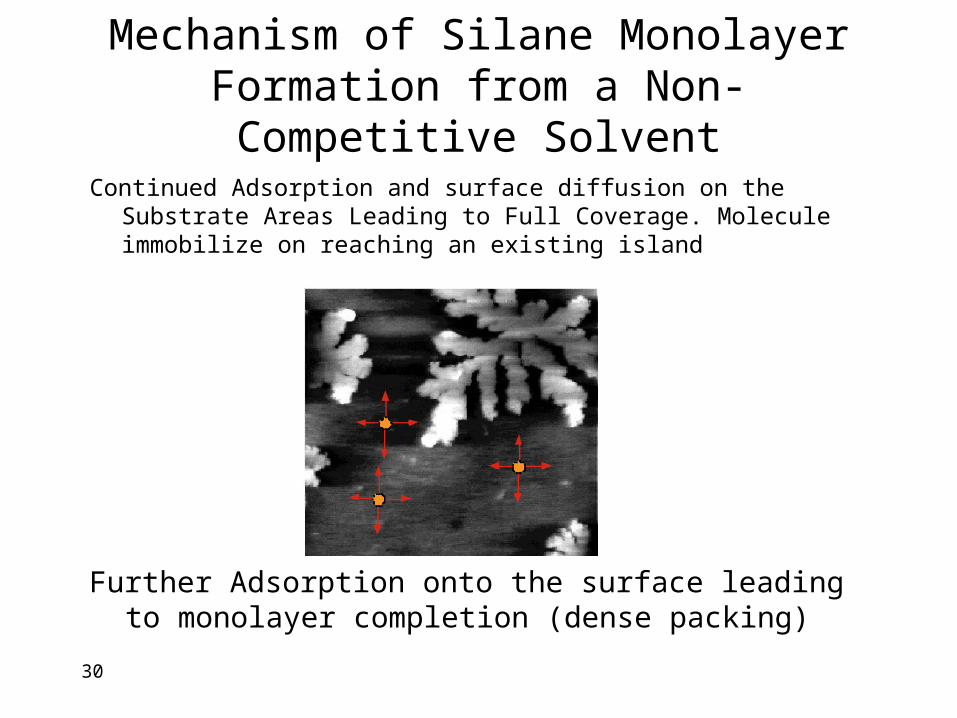
Mechanism of Silane Monolayer Formation from a Non-Competitive Solvent
Continued Adsorption and surface diffusion on the Substrate Areas Leading to Full Coverage. Molecule immobilize on reaching an existing island
Further Adsorption onto the surface leading to monolayer completion (dense packing)
31
56 5857
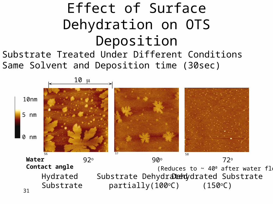
Effect of Surface Dehydration on OTS Deposition
• Substrate Treated Under Different Conditions• Same Solvent and Deposition time (30sec)
Hydrated Substrate Substrate Dehydrated partially(100oC)
Dehydrated Substrate(150oC)
10
0 nm
5 nm
10nm
Water Contact angle
92o 90o 72o
(Reduces to ~ 400 after water flow)
32
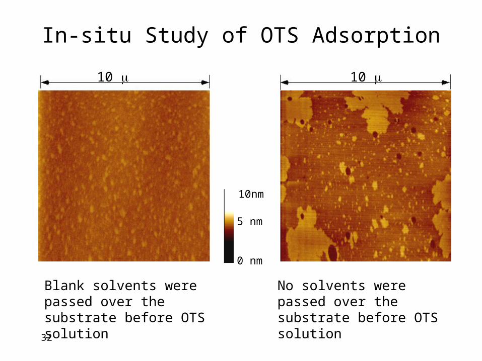
In-situ Study of OTS Adsorption
10 10
Blank solvents were passed over the substrate before OTS solution
No solvents were passed over the substrate before OTS solution
0 nm
5 nm
10nm
33
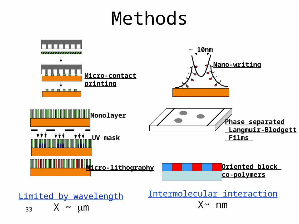
Methods
Micro-contactprinting
Monolayer
UV mask
Micro-lithography
Limited by wavelength
X ~ m
~ 10nm
Nano-writing
Phase separated Langmuir-Blodgett Films
Oriented block co-polymers
Intermolecular interaction
X~ nm
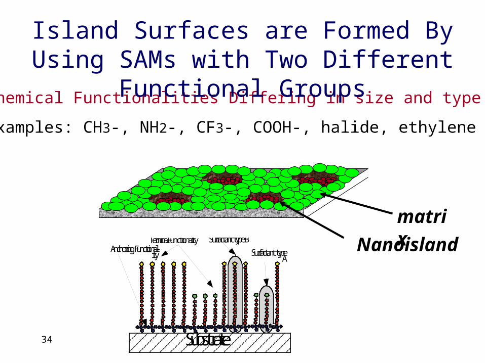
34
Nanoisland
matrix
Chemical Functionalities Differing in size and type
Examples: CH3-, NH2-, CF3-, COOH-, halide, ethylene oxide
Island Surfaces are Formed By Using SAMs with Two Different Functional Groups
Substrate
Terminal FunctionalityAnchoring Functional-
ity
Surfactant type B
Surfactant typeA
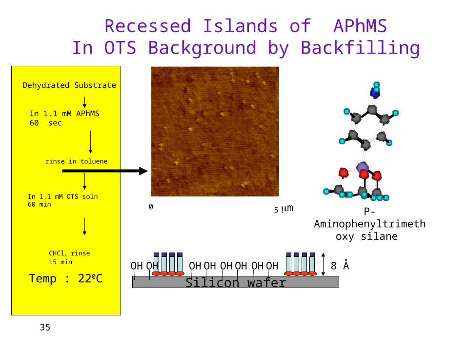
35
Temp : 220C
OTS
Dehydrated Substrate
In 1.1 mM APhMS 60 sec
rinse in toluene
In 1.1 mM OTS soln60 min
CHCl3 rinse15 min 8 Å
Recessed Islands of APhMSIn OTS Background by Backfilling
0 5 P-Aminophenyltrimethoxy silane
m
Silicon waferOHOH OHOH OHOH OHOH
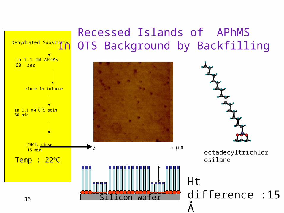
36
OTS
Ht difference :15 Å
Temp : 220C
Dehydrated Substrate
In 1.1 mM APhMS 60 sec
rinse in toluene
In 1.1 mM OTS soln60 min
CHCl3 rinse15 min 0 5
Recessed Islands of APhMSIn OTS Background by Backfilling
octadecyltrichlorosilanem
Silicon wafer
37
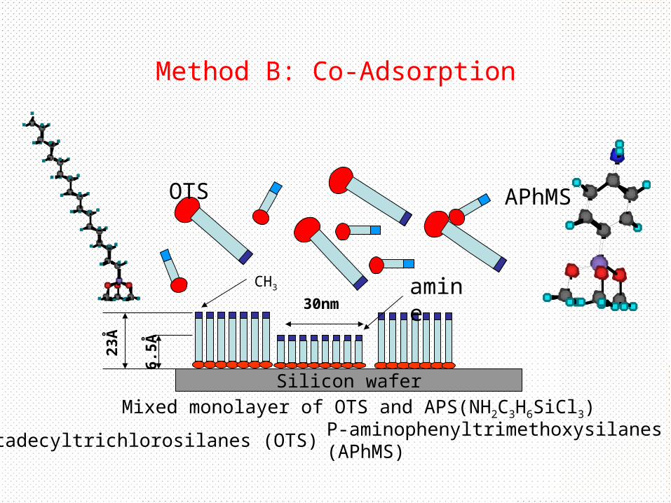
Method B: Co-Adsorption
Mixed monolayer of OTS and APS(NH2C3H6SiCl3)
Silicon wafer
CH3
23Å
6.5Å
30nmamine
APhMSOTS
octadecyltrichlorosilanes (OTS) P-aminophenyltrimethoxysilanes (APhMS)

38
Island Formation of Co-Adsorbed Self-assembling
SurfactantsAPhMS islands in OTS Matrix
0
5
10
15
20
25
30
10 13 15 18 22 25 28 31 34 37 40 43 50
Diameter (nm)
35 islands/µm2, average diameter: 28 nm,distribution width: 10 nm
3:1 OTS:APhMS; Chloroform
2mM total concentration of silane
39
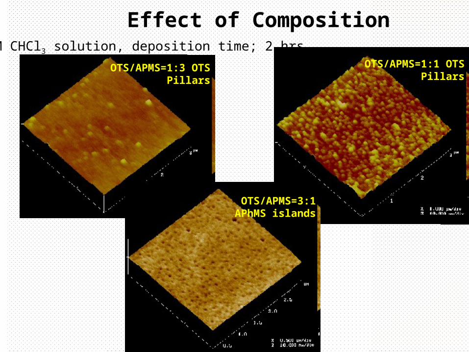
Effect of Composition2 mM CHCl3 solution, deposition time; 2 hrs
OTS/APMS=1:3 OTS Pillars
OTS/APMS=3:1 APhMS islands
OTS/APMS=1:1 OTS Pillars
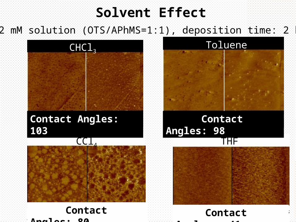
40 Contact Angles: 80 Contact Angles: 41
Solvent Effect2 mM solution (OTS/APhMS=1:1), deposition time: 2 hrs,
CHCl3Toluene
CCl4 THF
Contact Angles: 103 Contact Angles: 98
41
Effect of Solvent on Composition
Monolayer Composition in Mixed Adsorption is a balance between
• relative affinity of surfactants to the depositing solvent
• interfacial energy between the film formed and the depositing solution
42
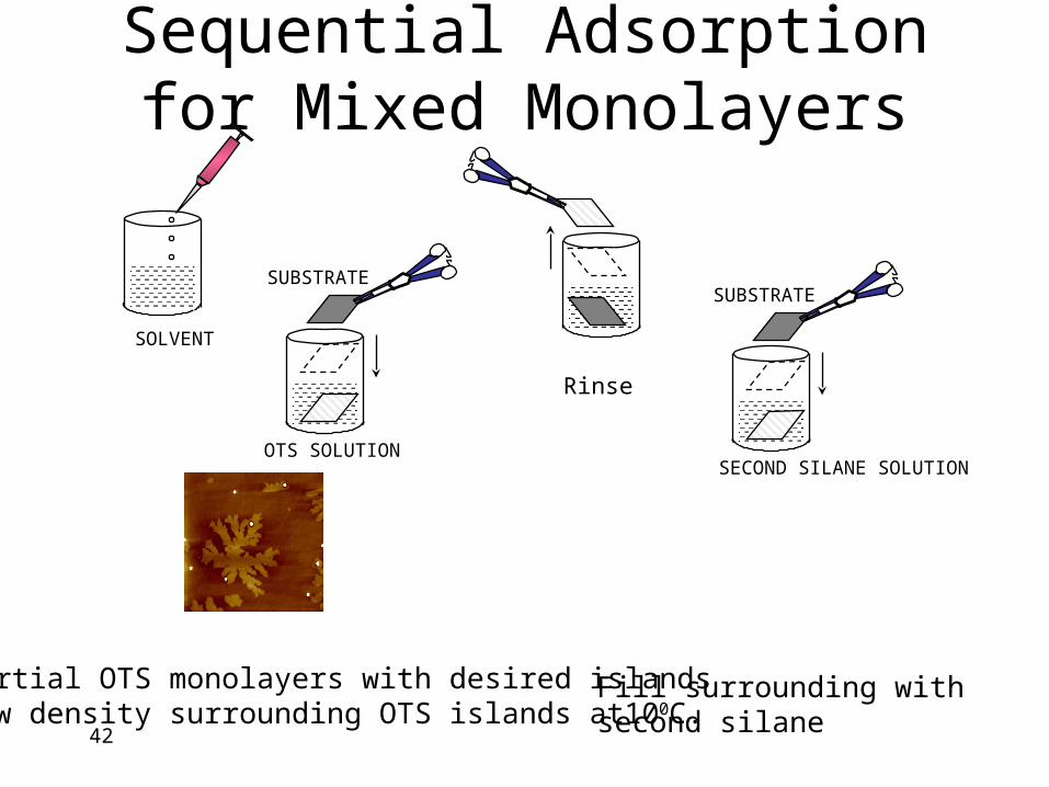
Sequential Adsorption for Mixed Monolayers
Partial OTS monolayers with desired islands Low density surrounding OTS islands at100C.
SOLVENT
SUBSTRATE
OTS SOLUTION
SUBSTRATE
SECOND SILANE SOLUTION
Rinse
Fill surrounding with second silane
43
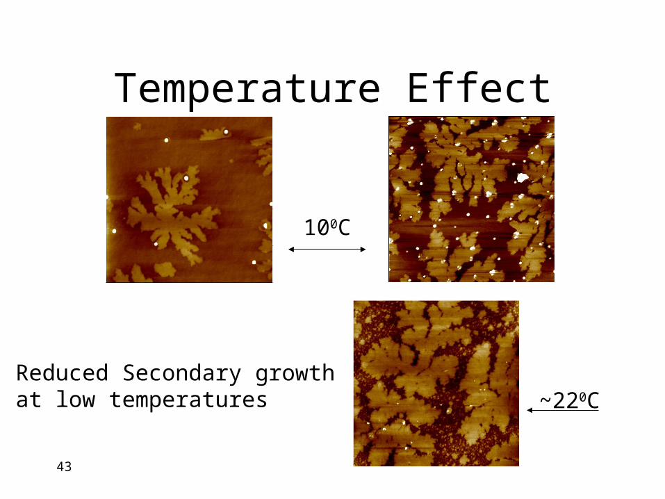
Temperature Effect
100C
~220CReduced Secondary growth at low temperatures
44
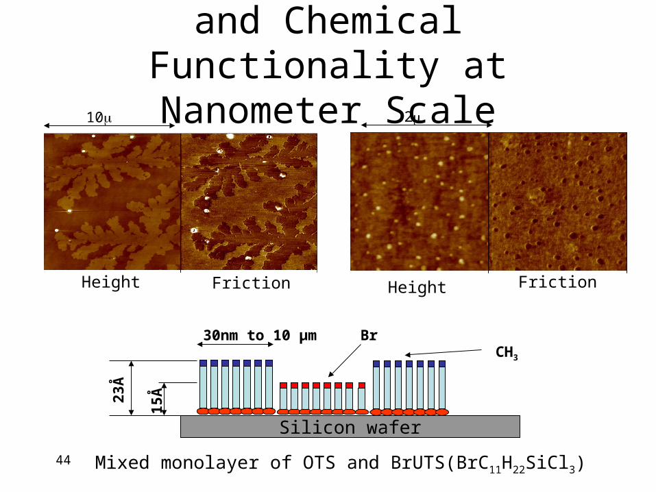
Control of Morphology and Chemical Functionality at
Nanometer Scale
Mixed monolayer of OTS and BrUTS(BrC11H22SiCl3)
Silicon wafer
CH3
23Å
15Å
30nm to 10 µm Br
10 2
Height HeightFriction Friction
45
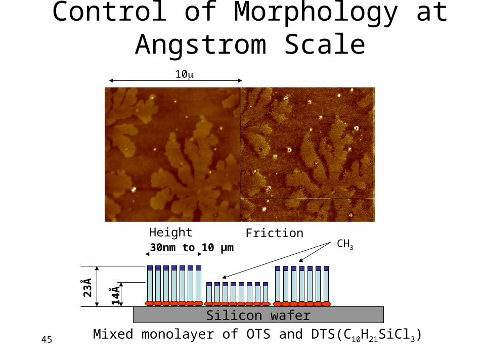
Control of Morphology at Angstrom Scale
Mixed monolayer of OTS and DTS(C10H21SiCl3)
Silicon wafer
CH3
23Å
14Å
30nm to 10 µm
10
Height Friction
46
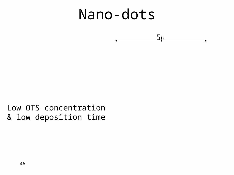
Nano-dots
5
Low OTS concentration & low deposition time