1 st on algebraic and symbolic computation -...
TRANSCRIPT

1st International Conference on
Algebraic and Symbolic Computation
PROCEEDINGS
09‐10 September, IST
Lisbon, Portugal
ISBN 978‐989‐96264‐5‐4

1st International Conference on Algebraic and Symbolic Computation, 09‐10 September, Lisbon, Portugal
ISBN 978‐989‐96264‐5‐4
SYMCOMP 2013 ‐ 1st International Conference on Algebraic and Symbolic Computation
Proceedings in digital support (pen drive)
Edited by APMTAC – Associação Portuguesa de Mecânica Teórica, Aplicada e Computacional
Editors: Amélia Loja (IDMEC/IST, ISEL), Joaquim Infante Barbosa (IDMEC/IST, ISEL), José
Alberto Rodrigues (CMAT/UM, ISEL)
September, 2013

1st International Conference on Algebraic and Symbolic Computation, 09‐10 September, Lisbon, Portugal
Introduction
The Organizing Committee of SYMCOMP2013 – 1st International Conference on Symbolic and Algebraic Computation welcomes all the participants and acknowledge the contribution of the authors to the success of this event.
This First International Conference on Symbolic and Algebraic Computation, is promoted by APMTAC - Associação Portuguesa de Mecânica Teórica, Aplicada e Computacional and it was organized in the context of IDMEC/IST - Instituto de Engenharia Mecânica. With this ECCOMAS Thematic Conference it is intended to bring together academic and scientific communities that are involved with Algebraic and Symbolic Computation in the most various scientific areas
SYMCOMP 2013 elects as main goals:
To establish the state of the art and point out innovative applications and guidelines on the use of Algebraic and Symbolic Computation in the numerous fields of Knowledge, such as Engineering, Physics, Mathematics, Economy and Management,...
To promote the exchange of experiences and ideas and the dissemination of works developed within the wide scope of Algebraic and Symbolic Computation.
To encourage the participation of young researchers in scientific conferences.
To facilitate the meeting of APMTAC members (Portuguese Society for Theoretical, Applied and Computational Mechanics) and other scientific organizations members dedicated to computation, and to encourage new memberships.
We invite all participants to keep a proactive attitude and dialoguing, exchanging and promoting ideas, discussing research topics presented and looking for new ways and possible partnerships to work to develop in the future.
The Executive Committee of SYMCOMP2013 wishes to express his gratitude for the cooperation of all colleagues involved in various committees, from the Scientific Committee, Organizing Committee and the Secretariat. We hope everyone has enjoyed helping to birth this project, which we are sure will continue in the future. Our thanks to you all.
o Amélia Loja (IDMEC/IST, ISEL) o Joaquim Infante Barbosa (IDMEC/IST, ISEL) o José Alberto Rodrigues (CMAT/UM, ISEL) o Tiago Silva (IDMEC/IST, ISEL) o Inês Jerónimo Barbosa (ISEL)
i

1st International Conference on Algebraic and Symbolic Computation, 09‐10 September, Lisbon, Portugal
CONFERENCE BOARD
Chair Person
Maria Amélia Ramos Loja, ADEM/ISEL ; IDMEC/LAETA
Área Departamental de Engenharia Mecânica
Instituto Superior de Engenharia de Lisboa
Rua Conselheiro Emídio Navarro, 1, 1959-007 Lisboa
Email : [email protected], [email protected]
EXECUTIVE COMMITTEE
Amélia Loja (IDMEC/IST, ISEL)
Joaquim Infante Barbosa (IDMEC/IST, ISEL)
José Alberto Rodrigues (CMAT/UM, ISEL)
Tiago Silva (IDMEC/IST, ISEL)
Inês Jerónimo Barbosa (ISEL)
ORGANIZING COMMITTEE
Amélia Loja (Chair, IDMEC/IST, ISEL) Lina Vieira (ESTeSL/IPL)
Ana Conceição (UAlg) Eva Sousa (ESTeSL/IPL)
Ana Madureira (ISEP/IPP) Luís Mateus (FA/UTL)
António Ferreira (IDMEC/FEUP) Paulo Vasconcelos (FEP)
Heitor Girão Pina (IDMEC/IST) Stéphane Louis Clain (UM)
João Calado (IDMEC/IST, ISEL) Victor Ferreira (FA/UTL)
Joaquim Infante Barbosa (IDMEC/IST, ISEL) Viriato Marques (ISEC/IPC)
José Alberto Rodrigues (CMAT/UM, ISEL)
ii
1st International Conference on Algebraic and Symbolic Computation, 09‐10 September, Lisbon, Portugal
SCIENTIFIC COMMITTEE
Amaro Rica da Silva (IST—Lisboa, Portugal) José César Sá (FEUP— Porto, Portugal)
Amélia Loja (IDMEC/IST, ISEL—Lisboa, Portugal) José Miranda Guedes (IDMEC/IST - Lisboa, Portugal)
Ana Conceição (UAlg—Algarve, Portugal) Józef Korbicz (University of Zielona-Góra, Poland)
Ana Madureira (ISEP/IPP, Porto, Portugal) Juarez Bento da Silva (UFSC, Santa Catarina, Brasil)
António J M Ferreira (IDMEC/FEUP— Porto, Portugal) Lina Vieira (ESTeSL/IPL, Lisboa, Portugal)
Aurélio Araújo (IDMEC/IST— Lisboa, Portugal) Luís Filipe Menezes (FCTUC— Coimbra, Portugal)
Carla Roque (INEGI—Porto, Portugal) Luís Mateus (FA/UTL—Lisbon, Portugal)
Carlos Alberto Mota Soares (IDMEC/IST—Lisboa, Portugal)
Lorenzo Dozio (Politecnico Milano, Italy)
Carlos Vaz de Carvalho (ISEP/IPP— Porto, Portugal) Marcin Kamiński (Technical University of Lodz, Poland)
Cristóvão Manuel Mota Soares (IDMEC/IST—Lisboa, Portugal)
Mário Graça (IST— Lisboa, Portugal)
Filipa Moleiro Duarte (IDMEC/IST, ISEL—Lisboa, Portugal)
Marta Cardoso de Oliveira (FCTUC— Coimbra, Portugal)
Gaetano Giunta (Centre de Recherches George Tudor, Luxembourg)
Miguel Matos Neves (IDMEC/IST— Lisboa, Portugal
Heitor Girão Pina (IDMEC/IST—Lisboa, Portugal) Pedro Vieira Alberto (FCTUC— Coimbra, Portugal)
Hélder Carriço Rodrigues (IDMEC/IST—Lisboa, Portugal) Renato Natal Jorge (FEUP— Porto, Portugal)
Helena Melão de Barros (FCTUC— Coimbra, Portugal) Silvio Simani (Università Ferrara, Italy)
Jaime Villate, (FEUP— Porto, Portugal) Stéphane Louis Clain (UM— Minho, Portugal)
James Uhomoibhi (Ulst University, UK) Teresa Restivo (FEUP— Porto, Portugal)
João Calado (IDMEC/IST, ISEL— Lisboa, Portugal) Victor Ferreira (FA/UTL, Lisbon, Portugal)
Joaquim Infante Barbosa (IDMEC/IST, ISEL— Lisboa) Victor M. Becerra (University of Reading -Reading,UK)
José Alberto Rodrigues (CMAT/UM, ISEL— Lisboa) Viriato Marques (ISEC/IPC—Coimbra, Portugal
SPONSORS
APMTAC – Associação Portuguesa de Mecânica, Teórica, Aplicada e Computacional;
IDMEC/LAETA – Instituto de Engenharia Mecânica;
ISEL/IPL – Instituto Superior de Engenharia de Lisboa
TIMBERLAKE Consultores
FCT - Foundation for Science and Technology - Project FCT: PTDC/ATP-AQI/5355/2012
iii
1st International Conference on Algebraic and Symbolic Computation, 09‐10 September, Lisbon, Portugal
ORGANIZING INSTITUTION
IDMEC/LAETA – Instituto de Engenharia Mecânica/Laboratório Associado de Energia, Transportes e Aeronáutica.
PLACE OF THE EVENT
Instituto Superior Técnico
Avenida Rovisco Pais, 1049-001 Lisboa
iv

Contents
INTRODUCTION i
CONTENTS v
SP 01 - SYMBOLIC COMPUTING IN PROBABILISTIC ANDSTOCHASTIC ANALYSIS 1
IP 01 - ECONOMIC GROWTH MODELS: SYMBOLIC ANDNUMERICAL COMPUTATIONS 21
IP 02 - AN OVERVIEW OF SYMBOLIC COMPUTATION ONOPERATOR THEORY 39
ID 01 - IDEVELOPMENT OF A VISUAL LOOP CLOSURE DE-TECTOR IN MATLAB 73
ID 02 - THE INFLUENCE OF COUNT”S NUMBER IN MY-OCARDIUM IN THE DETERMINATION OF REPRODUCIBLEPARAMETERS IN GATED-SPECT STUDIES SIMULATEDWITH GATE 93
ID 03 - REPRODUCIBILITY OF MYOCARDIAL LESIONS SIM-ULATED ON A VIRTUAL PHANTOM 95
ID 04 - OPTIMIZE THE POSITION OF MECHANICAL COM-PONENTS OF AN EXTERNAL FIXATOR USING NEURALNETWORKS AND GENETIC ALGORITHMS 99
ID 05 - GOVERNMENT SPENDING OBJECTIVES IN A DIS-CRETE STOCHASTIC GROWTH MODEL WITH TAXES 111
ID 06 - DYNAMIC POLITICAL EFFECTS IN A NEOCLASSICGROWTH MODEL WITH HEALTHCARE AND CREATIVEACTIVITIES 129
v

ID 07 - ECONOMIC GROWTH AND EQUILIBRIA: A SYM-BOLIC APPROACH 137
ID 08 - F-TOOL 2.0: EXPLORING THE LOGISTIC FUNCTIONIN THE CLASSROOM 149
ID 09 - TWO-VARIABLE LINEAR PROGRAMMING: A GRAPH-ICAL TOOL WITH MATHEMATICA 159
ID 10 - EXPLORING THE SPECTRA OF SINGULAR INTE-GRAL OPERATORS WITH RATIONAL COEFFICIENTS 175
ID 11 - AUTOMATIC DERIVATION OF PLATE EQUATIONSOF MOTION 195
ID 12 - A NEW FINITE VOLUME SCHEME FOR INCOM-PRESSIBLE FLUID FLOW 197
ID 13 - BENDING OF A BEAM WITH FINITE VOLUME SCHEMES207
ID 14 - VERY HIGH-ORDER TIME SCHEME FOR THE FI-NITE VOLUME METHOD 219
ID 15 - USING SYMMETRY GROUPS TO SOLVE DIFFER-ENTIAL EQUATIONS: ANALYTICAL AND NUMERICALPERSPECTIVES 229
ID 16 - SOLVING SECOND-ORDER LINEAR ORDINARY DIF-FERENTIAL EQUATIONS INTERACTIVELY 243
ID 17 - SYSTEMATIC SYMBOLIC GENERATION OF ADDI-TIVE AND MULTIPLICATIVE DISCRETE CONSTITUENTS259
ID 18 - OPTIMAL IDENTIFICATION OF ELASTIC SUPPORTPARAMETERS ON BERNOULLI-EULER BEAMS 291
ID 19 - TOWARD AMBIENT INTELLIGENCE FOR INTEL-LIGENT MANUFACTURING SCHEDULING IN DECISIONMAKING 311
ID 20 - DYNAMIC ADAPTATION FOR SCHEDULING UNDERRUSH MANUFACTURING ORDERS WITH CASE-BASEDREASONING 331
ID 21 - MULTI-AGENT MECHANICAL SYSTEMS MANEU-VERING WITH DISTRIBUTED MODEL PREDICTIVE CON-TROL TECHNIQUES 345
vi

ID 22 - USING SYMBOLIC COMPUTATION IN THE DETEC-TION OF FRICTIONAL INSTABILITIES 361
ID 23 - ANALYTICAL SOLUTION FOR RECTANGULAR PLATESWITH VISCOELASTIC AND PIEZOELECTRIC LAYERS 373
ID 24 - MODELLING OF LAMINATED COMPOSITE MULTI-CELL STRUCTURE USING PARTICLE SWARM OPTIMIZA-TION 375
ID 25 - CHARACTERIZATION AND MODELING OF BUILD-ING CRACKS USING 3D LASER SCANNING AS REHA-BILITATION SUPPORT 386
ID 26 - A NUMERICAL SOLUTION FOR STRUCTURAL VI-BRATION PROBLEMS 400
ID 27 - VISUAL PROGRAMMING AS TOOL FOR ARCHITEC-TURAL DESIGN 412
ID 28 - AN EXPEDITIOUS METHODOLOGY TO CORRECTTHE CLOSURE ERROR OF POINT CLOUDS REGISTRA-TION 422
SYMCOMP 2013 Lisbon, 9-10 September 2013
©ECCOMAS, Portugal
VISUAL PROGRAMMING AS TOOL FOR ARCHITECTURAL
DESIGN
Luís Mateus1*, Filipa Roseta2 and Francisco Vaz Monteiro3
1: ArcHC3D research group CIAUD, Faculty of Architecture Technical University of Lisbon
Rua Sá Nogueira, Pólo Universitário, Alto da Ajuda, 1349-055 Lx [email protected], web: http://www.fa.utl.pt/~lmmateus
2: Project Department
CIAUD, Faculty of Architecture Technical University of Lisbon
Rua Sá Nogueira, Pólo Universitário, Alto da Ajuda, 1349-055 Lx [email protected]
3: Roseta Vaz Monteiro Arquitectos, Lda
Rua Pinheiro Chagas, nº 73, 3º dto, 1050-176 Lx [email protected], http: www.rosetavazmonteiro.com
Keywords: Visual programming, Grasshopper, architectural design, digital fabrication, laser scanning
Abstract This paper describes the use of the visual programming interface Grasshopper, which runs in Rhinoceros software, in the development a parametric paneling solution for the design of a kiosk’s interior cladding. The specific design problem includes: i) the geometric definition of the inner surfaces of the kiosk, ii) the subdivision of the surfaces into small components defining a stereotomic pattern, taking into account the milling fabrication technology that will be used to fabricate the pieces, and iii) laying out the numbered pieces for fabrication. Firstly, we describe the programming interface; secondly, we explain the constraints of the problem and how they were used as parameters; thirdly, we describe the parametric modeling workflow; and, fourthly, we explain how the fabrication technology and the materials selected for the fabrication affected the conceptual strategy. Additionally, we indicate how this kind of modeling strategy can be used in other contexts, such as reverse engineering using laser scanning data as input.
412

Luís Mateus1*, Filipa Roseta2 and Francisco Vaz Monteiro3
1. INTRODUCTION “New tools and new thinking go together”. This is the way Mitchell & McCulough start one of the chapters of Digital Design Media [1], a seminal book about the use of computational media in the context of architecture. In earlier stages, computers were only used as facilitators of well-known procedures which were translated into digital format. Today, it is expected that the use of computers will not only help to expand the architect’s conscience about the surrounding world, but also broaden his ability to intervene in an intelligent way [2]. Parametric Design presents a new path to conceive architectural spaces. Traditionally, when modelling, it can be relatively easy to generate a single solution for a specific problem; however, as the complexity increases, requiring changes to test different hypotheses for a solution, modelling becomes a tedious and time-consuming job. The need to change a simple length in a model may lead to several hours modelling if the model does not change automatically [3]. The solution for this kind of problem is parametric modelling. For this paper, when we refer parametric modelling, we do not refer to tools that provide us final solutions, such as wall or window types. These tools can be found in software like ArchiCad (http://www.graphisoft.com/archicad/) or Revit (http://www.autodesk.com/products/autodesk-revit-family/overview). For this paper, we are considering tools that enable the architect to explore the process of form finding with an almost unlimited range of creative freedom. This freedom comes with the need to master some geometric and mathematical concepts in a consistent way. This kind of tool can help the architect “catch the curve” or “create the curve” [4]. “To catch the curve” means to rationalize a solution that is conceived by traditional media, such as hand-drawing. To “create the curve” means that the computer can deal with levels of complexity and amounts of information that are not possible for human reasoning. We are referring to tools like Vasari (http://autodeskvasari.com/) for Revit or Grasshopper (http://www.grasshopper3d.com/) for Rhinoceros (http://www.rhino3d.com/). The work described in this paper lies aimed to both “catch the curve” and “create the curve” and was implemented with Grasshopper.
1.1. The programming interface In this sub-section we will describe the programming interface used to develop the parametric modelling solution. Grasshopper, being a visual programming tool, does not require the user to have high skills of programming or scripting. It works in a more intuitive basis and is particularly suited for designers who want to program generative solutions. Instead of writing text to describe the operations that the computer should perform, the user selects and concatenates specific objects using wires to describe the desired algorithm. There are two basic types of objects: parameters and components. Parameters store data and components perform operations. Components are divided in three parts: i) input parameters, ii) the component function itself, and iii) output parameters. Parameters are of two types: one type that inherits data from other components; and another type that does not inherit data, transmitting the data it stores to following components. The Grasshopper objects are grouped in categories (parameters, mathematical functions, sets, vector, curve, surface, mesh, intersection, transform). In each category we find sub-groups of objects. For example in the
413
Luís Mateus1*, Filipa Roseta2 and Francisco Vaz Monteiro3
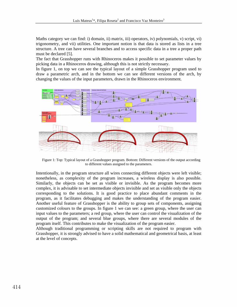
Maths category we can find: i) domain, ii) matrix, iii) operators, iv) polynomials, v) script, vi) trigonometry, and vii) utilities. One important notion is that data is stored as lists in a tree structure. A tree can have several branches and to access specific data in a tree a proper path must be declared [5]. The fact that Grasshopper runs with Rhinoceros makes it possible to set parameter values by picking data in a Rhinoceros drawing, although this is not strictly necessary. In figure 1, on top we can see the typical layout of a simple Grasshopper program used to draw a parametric arch, and in the bottom we can see different versions of the arch, by changing the values of the input parameters, drawn in the Rhinoceros environment.
Figure 1: Top: Typical layout of a Grasshopper program. Bottom: Different versions of the output according
to different values assigned to the parameters.
Intentionally, in the program structure all wires connecting different objects were left visible; nonetheless, as complexity of the program increases, a wireless display is also possible. Similarly, the objects can be set as visible or invisible. As the program becomes more complex, it is advisable to set intermediate objects invisible and set as visible only the objects corresponding to the solutions. It is good practice to place abundant comments in the program, as it facilitates debugging and makes the understanding of the program easier. Another useful feature of Grasshopper is the ability to group sets of components, assigning customized colours to the groups. In figure 1 we can see: a green group, where the user can input values to the parameters; a red group, where the user can control the visualization of the output of the program; and several blue groups, where there are several modules of the program itself. This contributes to make the visualization of the program easier. Although traditional programming or scripting skills are not required to program with Grasshopper, it is strongly advised to have a solid mathematical and geometrical basis, at least at the level of concepts.
414
Luís Mateus1*, Filipa Roseta2 and Francisco Vaz Monteiro3
2. THE ARCHITECTURAL PROBLEM TO BE SOLVED: A KIOSK In this section we present a generic description of the design problem which needed to be solved. The architectural office Roseta Vaz Monteiro Arquitectos (www.rosetavazmonteiro.com) was commissioned to design a prototype for a kiosk that should be adaptable to similar situations, but different physical contexts. The project brief included that the kiosk was to be repeatedly build on several sites. The idea was to design an architectural object with equivalent topology, but not necessarily the same size or shape. This need for repeatability along with the intended architectural expression, with inner curved warped surfaces, made it difficult to adopt a traditional design methodology. It became clear that a parametric modelling approach would be best suited. In addition, there was restriction arising from the chosen material, cork, which, considering all previous conditions, further led to choosing milling as the fabrication technology.
3. THE MODELING STEPS The specific design problem to solve includes: i) the geometric definition of the inner surfaces of the kiosk, ii) the subdivision of the surfaces into small components defining a stereotomic pattern taking into account the milling fabrication technology that will be used to fabricate the pieces, and iii) laying out the numbered pieces for fabrication.
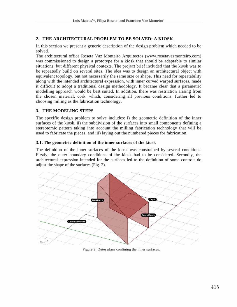
3.1. The geometric definition of the inner surfaces of the kiosk The definition of the inner surfaces of the kiosk was constrained by several conditions. Firstly, the outer boundary conditions of the kiosk had to be considered. Secondly, the architectural expression intended for the surfaces led to the definition of some controls do adjust the shape of the surfaces (Fig. 2).
Figure 2: Outer plans confining the inner surfaces.
415
Luís Mateus1*, Filipa Roseta2 and Francisco Vaz Monteiro3
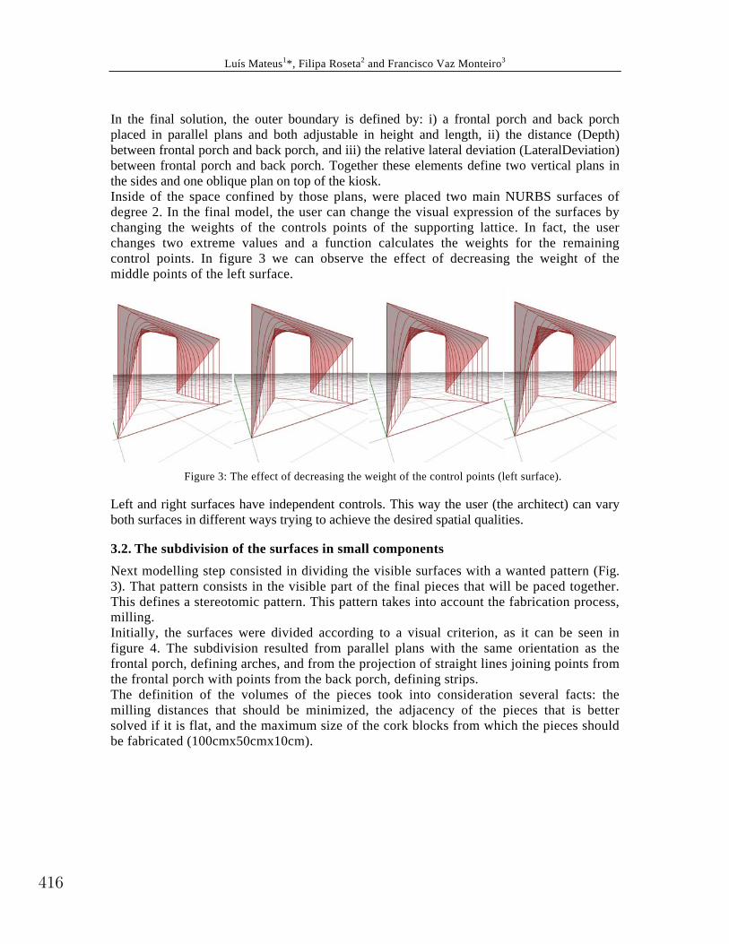
In the final solution, the outer boundary is defined by: i) a frontal porch and back porch placed in parallel plans and both adjustable in height and length, ii) the distance (Depth) between frontal porch and back porch, and iii) the relative lateral deviation (LateralDeviation) between frontal porch and back porch. Together these elements define two vertical plans in the sides and one oblique plan on top of the kiosk. Inside of the space confined by those plans, were placed two main NURBS surfaces of degree 2. In the final model, the user can change the visual expression of the surfaces by changing the weights of the controls points of the supporting lattice. In fact, the user changes two extreme values and a function calculates the weights for the remaining control points. In figure 3 we can observe the effect of decreasing the weight of the middle points of the left surface.
Figure 3: The effect of decreasing the weight of the control points (left surface).
Left and right surfaces have independent controls. This way the user (the architect) can vary both surfaces in different ways trying to achieve the desired spatial qualities.
3.2. The subdivision of the surfaces in small components Next modelling step consisted in dividing the visible surfaces with a wanted pattern (Fig. 3). That pattern consists in the visible part of the final pieces that will be paced together. This defines a stereotomic pattern. This pattern takes into account the fabrication process, milling. Initially, the surfaces were divided according to a visual criterion, as it can be seen in figure 4. The subdivision resulted from parallel plans with the same orientation as the frontal porch, defining arches, and from the projection of straight lines joining points from the frontal porch with points from the back porch, defining strips. The definition of the volumes of the pieces took into consideration several facts: the milling distances that should be minimized, the adjacency of the pieces that is better solved if it is flat, and the maximum size of the cork blocks from which the pieces should be fabricated (100cmx50cmx10cm).
416

Luís Mateus1*, Filipa Roseta2 and Francisco Vaz Monteiro3
Figure 4: Outer plans confining the inner surfaces.
In figure 5 we can observe two possible solutions for the assembly of the pieces.
Figure 5: Two possible solutions for the assembly of the pieces.
A colour code was added as an alert. In the left solution (figure 5) we have red, blue and green pieces. Red, green and blue mean that length, width and milling distance, respectively, exceed specified thresholds. To overcome this issue the user has to assign different values to one or more parameters. The solution in right corresponds to a different
417
Luís Mateus1*, Filipa Roseta2 and Francisco Vaz Monteiro3
subdivision in the depth direction. By changing this value, all pieces lie within the specified thresholds and, therefore, correspond to a valid solution.
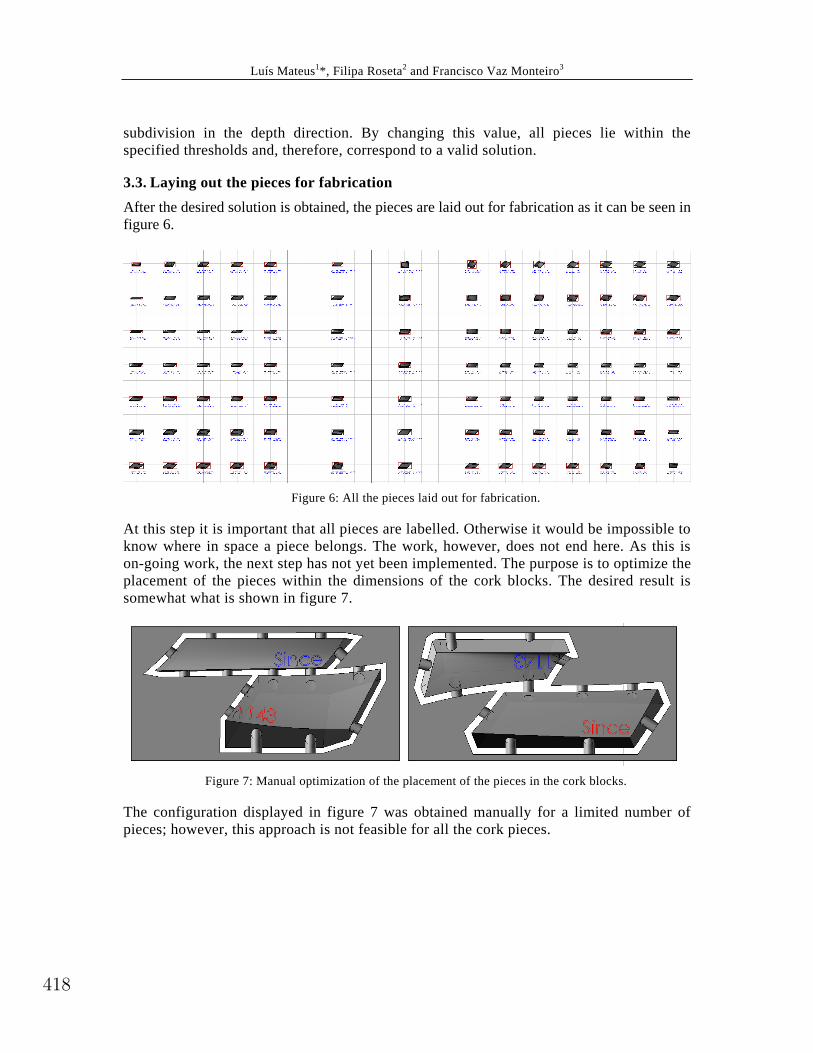
3.3. Laying out the pieces for fabrication After the desired solution is obtained, the pieces are laid out for fabrication as it can be seen in figure 6.
Figure 6: All the pieces laid out for fabrication.
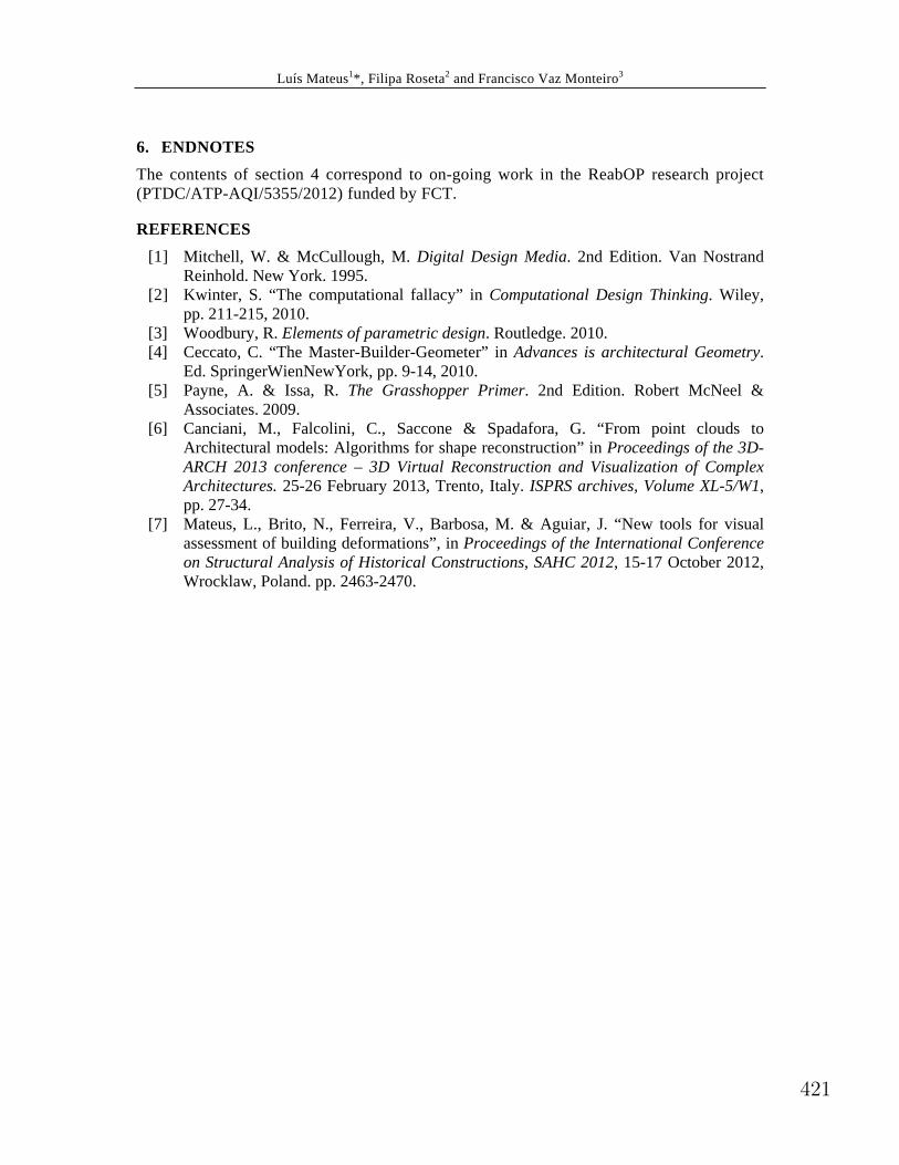
At this step it is important that all pieces are labelled. Otherwise it would be impossible to know where in space a piece belongs. The work, however, does not end here. As this is on-going work, the next step has not yet been implemented. The purpose is to optimize the placement of the pieces within the dimensions of the cork blocks. The desired result is somewhat what is shown in figure 7.
Figure 7: Manual optimization of the placement of the pieces in the cork blocks.
The configuration displayed in figure 7 was obtained manually for a limited number of pieces; however, this approach is not feasible for all the cork pieces.
418

Luís Mateus1*, Filipa Roseta2 and Francisco Vaz Monteiro3
4. OTHER APPLICATIONS: THE STUDY OF EXISTING BUILDINGS Another possible application of this kind of approach to modelling can be the fitting of knowledge based models [6] to surveyed data. Surveyed data can be, for example, point clouds from laser scanning or photogrammetry. The accuracy of laser scanning and photogrammetric surveys allows us to deduce the rules underlying the existing built structure. Then, these rules can be put in the form of algorithms that will be used to further study the built typologies. This can help us expand our understanding about the constructive systems employed, about the underlying geometries and architectural concepts. The example presented in this section is the study of the main dome of “Arco da Rua Augusta” in Lisbon [7]. In the example of figure 8 we can observe a point cloud survey (left side) and a parametric knowledge based model (right side) of the same dome. Since the knowledge based model is parametric, the surveyed point clouds will be used as constraint data to find a best fit solution.
Figure 8: Dome of “Arco da Rua Augusta”. Left: Point cloud survey. Right: Parametric knowledge
based model.
By having a parametric model, it is possible to understand that the real constructive solution (the dome itself) is one of many possible solutions contained in the parametric system (Fig. 9). The examples of figure 9 are all instances generated by the same program that generates a solution for the real “Arco da Rua Agusta”. This represents an important possibility for the study of existing buildings; furthermore, it is a good example where new technologies and procedures can be used to better understand architectural heritage and to bring new insights into historic buildings.
419

Luís Mateus1*, Filipa Roseta2 and Francisco Vaz Monteiro3
Figure 8: Dome of “Arco da Rua Augusta”. Left: Point cloud survey. Right: Parametric knowledge
based model.
5. CONCLUSIONS The examples presented in this paper aim to show how visual programming can be used as an effective tool both for architectural design and for the understanding of existing buildings in ways that traditional media cannot be used. This represents a paradigm shift in the field of architecture, meaning new possibilities for the architect. This also means the need for new skills, without the demand to master traditional programming languages or scripting. These new skills are within the field of geometric and mathematical concepts with effective visual counterparts. For this approach to architectural design, a rationalizing attitude is needed, since it is important to understand that some design tasks can be thought of as algorithms. This approach does not bring about less creativity, but, on the contrary, welcomes computational tools as one more path to expand our ability to conceive architectural designs. It also means a comprehensive approach to design, where more variables have to be taken into consideration in early stages of the creative process. With these tools it is possible to sketch ideas in a new format that transcends the traditional drawing, allowing the architect to quickly explore a wide range of solutions effectively. With this approach, the idea of single solution has to be replaced by the idea of a family of solutions embedded in the parametric system. This means that the ability to change the values assigned to the parameters enables automatically updating a solution or generate a complete new one.
420
Luís Mateus1*, Filipa Roseta2 and Francisco Vaz Monteiro3
6. ENDNOTES The contents of section 4 correspond to on-going work in the ReabOP research project (PTDC/ATP-AQI/5355/2012) funded by FCT.
REFERENCES [1] Mitchell, W. & McCullough, M. Digital Design Media. 2nd Edition. Van Nostrand
Reinhold. New York. 1995. [2] Kwinter, S. “The computational fallacy” in Computational Design Thinking. Wiley,
pp. 211-215, 2010. [3] Woodbury, R. Elements of parametric design. Routledge. 2010. [4] Ceccato, C. “The Master-Builder-Geometer” in Advances is architectural Geometry.
Ed. SpringerWienNewYork, pp. 9-14, 2010. [5] Payne, A. & Issa, R. The Grasshopper Primer. 2nd Edition. Robert McNeel &
Associates. 2009. [6] Canciani, M., Falcolini, C., Saccone & Spadafora, G. “From point clouds to
Architectural models: Algorithms for shape reconstruction” in Proceedings of the 3D-ARCH 2013 conference – 3D Virtual Reconstruction and Visualization of Complex Architectures. 25-26 February 2013, Trento, Italy. ISPRS archives, Volume XL-5/W1, pp. 27-34.
[7] Mateus, L., Brito, N., Ferreira, V., Barbosa, M. & Aguiar, J. “New tools for visual assessment of building deformations”, in Proceedings of the International Conference on Structural Analysis of Historical Constructions, SAHC 2012, 15-17 October 2012, Wrocklaw, Poland. pp. 2463-2470.
421