1. specification - neon.lofis.netneon.lofis.net/ssangyong/service_manuals/c200/c200_wml_411.pdf ·...
TRANSCRIPT
11-3
ELECTRONIC STABILITY PROGRAMkorando 2010.10
0000-00
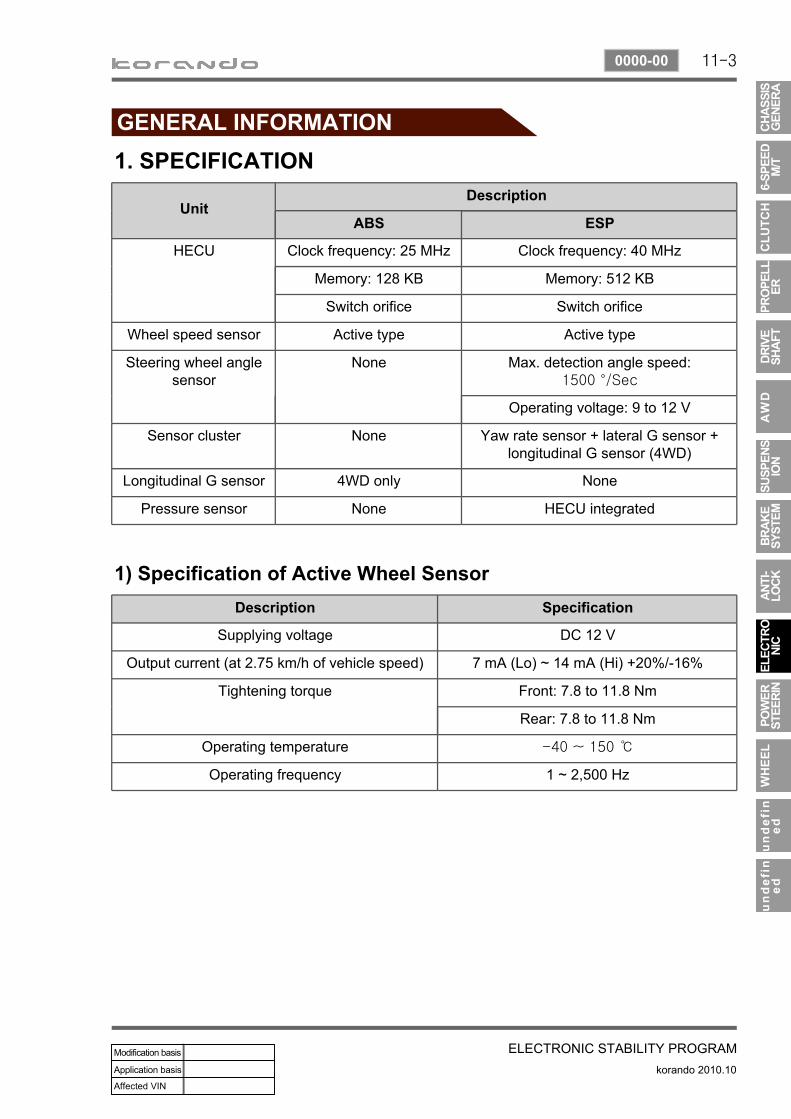
1. SPECIFICATION
1) Specification of Active Wheel SensorDescription Specification
Supplying voltage DC 12 V
Output current (at 2.75 km/h of vehicle speed) 7 mA (Lo) ~ 14 mA (Hi) +20%/-16%
Tightening torque Front: 7.8 to 11.8 Nm
Rear: 7.8 to 11.8 Nm
Operating temperature -40 ~ 150 ℃
Operating frequency 1 ~ 2,500 Hz
UnitDescription
ABS ESP
HECU Clock frequency: 25 MHz Clock frequency: 40 MHz
Memory: 128 KB Memory: 512 KB
Switch orifice Switch orifice
Wheel speed sensor Active type Active type
Steering wheel angle sensor
None Max. detection angle speed:1500 °/Sec
Operating voltage: 9 to 12 V
Sensor cluster None Yaw rate sensor + lateral G sensor + longitudinal G sensor (4WD)
Longitudinal G sensor 4WD only None
Pressure sensor None HECU integrated
11-4
korando 2010.10
0000-00
ELECTRONIC STABILITY PROGRAM
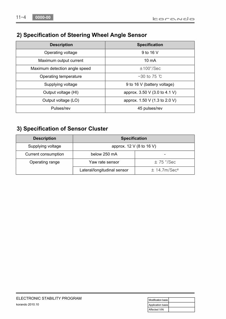
2) Specification of Steering Wheel Angle Sensor Description Specification
Operating voltage 9 to 16 V
Maximum output current 10 mA
Maximum detection angle speed ±100°/Sec
Operating temperature -30 to 75 ℃
Supplying voltage 9 to 16 V (battery voltage)
Output voltage (HI) approx. 3.50 V (3.0 to 4.1 V)
Output voltage (LO) approx. 1.50 V (1.3 to 2.0 V)
Pulses/rev 45 pulses/rev
3) Specification of Sensor ClusterDescription Specification
Supplying voltage approx. 12 V (8 to 16 V)
Current consumption below 250 mA -
Operating range Yaw rate sensor ± 75 °/Sec
Lateral/longitudinal sensor ± 14.7m/Sec²
11-5
ELECTRONIC STABILITY PROGRAMkorando 2010.10
0000-00
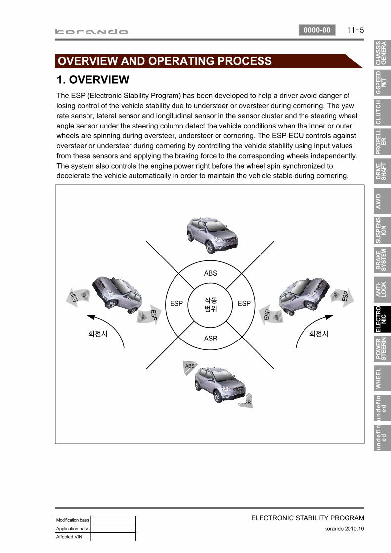
1. OVERVIEWThe ESP (Electronic Stability Program) has been developed to help a driver avoid danger of losing control of the vehicle stability due to understeer or oversteer during cornering. The yaw rate sensor, lateral sensor and longitudinal sensor in the sensor cluster and the steering wheel angle sensor under the steering column detect the vehicle conditions when the inner or outer wheels are spinning during oversteer, understeer or cornering. The ESP ECU controls against oversteer or understeer during cornering by controlling the vehicle stability using input values from these sensors and applying the braking force to the corresponding wheels independently. The system also controls the engine power right before the wheel spin synchronized to decelerate the vehicle automatically in order to maintain the vehicle stable during cornering.
11-6
korando 2010.10
0000-00
ELECTRONIC STABILITY PROGRAM
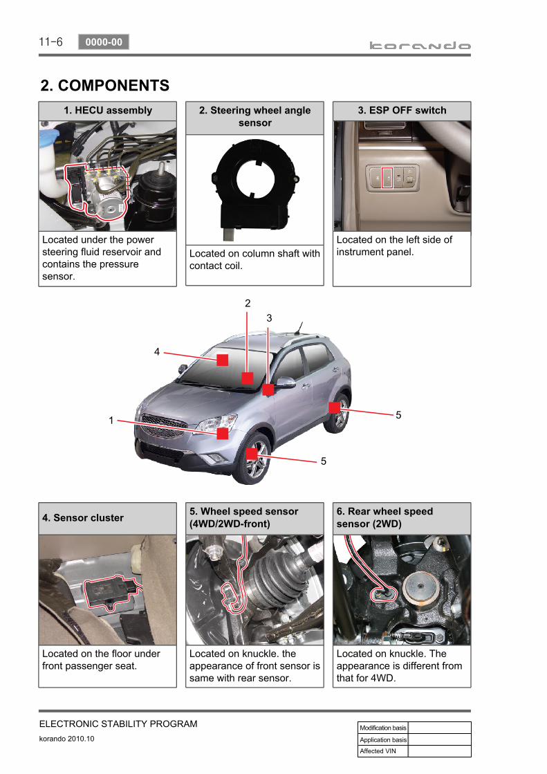
1. HECU assembly
Located under the power steering fluid reservoir and contains the pressure sensor.
3. ESP OFF switch
Located on the left side of instrument panel.
2. COMPONENTS2. Steering wheel angle
sensor
Located on column shaft with contact coil.
4. Sensor cluster
Located on the floor under front passenger seat.
5. Wheel speed sensor (4WD/2WD-front)
Located on knuckle. the appearance of front sensor is same with rear sensor.
6. Rear wheel speed sensor (2WD)
Located on knuckle. The appearance is different from that for 4WD.
11-7
ELECTRONIC STABILITY PROGRAMkorando 2010.10
0000-00
3. PRECAUTIONS
The warning lamp flashes and warning beep sounds when the ESP is operatingWhen the ESP operates during vehicle movement, the ESP warning lamp on the instrument panel flashes and beep comes on every 0.1 second. The ESP system is only a supplementary device for comfortable driving. When the vehicle exceeds its physical limits, it cannot be controlled.Do not rely on the system. Keep on the safe driving.
Feeling when ESP is workingWhen the ESP system activates, the feeling can be different depending on vehicle driving conditions.For example, you will feel differently when the ESP system is activated during the ABS is operating with the brakes applied and when the brakes are not applied on a curve.If the ESP system operates when the brake is applied, the brake pressure will be increased on the corresponding wheel which already has braking pressure for the ESP controls.
ARP OperationDuring the ARP operation, vehicle safety (rollover prevention) takes the first priority and thus, stronger engine control is in effect. Consequently, the vehicle speed decreases rapidly, so the driver must take caution for the vehicle may drift away from the lane.
Noise and vibration that driver feels when ESP system is operating The ESP system may transfer noise and vibration to the driver due to the pressure changes caused by the motor and valve operations in a very short period of time. And, keep in mind that the output and vehicle speed could be decreased without rpm increase due to the ASR function that controls the engine power.
11-8
korando 2010.10
0000-00
ELECTRONIC STABILITY PROGRAM
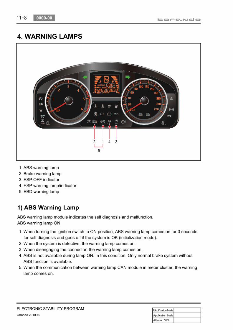
4. WARNING LAMPS
1) ABS Warning LampABS warning lamp module indicates the self diagnosis and malfunction.ABS warning lamp ON:
When turning the ignition switch to ON position, ABS warning lamp comes on for 3 seconds for self diagnosis and goes off if the system is OK (initialization mode).When the system is defective, the warning lamp comes on.When disengaging the connector, the warning lamp comes on.ABS is not available during lamp ON. In this condition, Only normal brake system without ABS function is available.When the communication between warning lamp CAN module in meter cluster, the warning lamp comes on.
1.
2.3.4.
5.
ABS warning lampBrake warning lampESP OFF indicatorESP warning lamp/indicatorEBD warning lamp
1.2.3.4.5.
11-9
ELECTRONIC STABILITY PROGRAMkorando 2010.10
0000-00
2) EBD (Electronic Brake-force Distribution) Warning Lamp (Brake Warning Lamp)EBD warning lamp when the system perform the self diagnosis and when it detects the malfunction of EBD system. However, the brake warning lamp comes on regardless of EBD when the parking brake is applied.EBD warning lamp ON:
When turning the ignition switch to ON position, ABS warning lamp and the brake warning lamp comes on for 3 seconds for self diagnosis and goes off if the system is OK (initialization mode).When applying the parking brake, the brake warning lamp comes on.When the brake fluid is not sufficient, the brake warning lamp comes on.When disengaging the connector, the warning lamp comes on.When the system is defective, ABS warning lamp and the brake warning lamp come on simultaneously.
1.
2.3.4.5.
When the solenoid valve is defectiveWhen one or more wheel sensors are defectiveWhen ABS HECU is defectiveWhen the voltage is abnormalWhen valve relay is defective
a.b.c.d.e.When the communication between warning lamp CAN module in meter cluster, the warning lamp comes on.
6.
3) ESP OFF IndicatorESP OFF indicator ON:
When turning the ignition switch to ON position, ESP warning lamp comes on for 3 seconds for self diagnosis and goes off if the system is OK (initialization mode).When the ESP OFF switch is pressed to turn off ESP function, ESP OFF indicator comes on.
1.
2.
4) ESP Warning LampESP warning lamp ON:When turning the ignition switch to ON position, ESP warning lamp comes on for 3 seconds for self diagnosis and goes off if the system is OK (initialization mode).When the system is defective, the warning lamp comes on.When the ESP function is activated, ESP warning lamp blinks with the interval of 2 Hz.When the communication between warning lamp CAN module in meter cluster, the warning lamp comes on.
1.2.
3.4.5.
5) ESP OFF SwitchIf ESP OFF switch is pressed, ESP function is deactivated and the ESP OFF indicator in the instrument cluster comes on.To resume the ESP function, press the switch again. At this time, ESP OFF indicator goes out.
11-10
korando 2010.10
0000-00
ELECTRONIC STABILITY PROGRAM
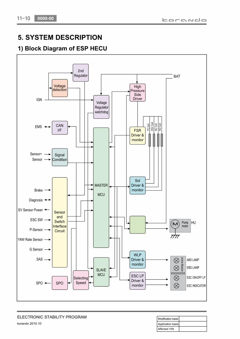
5. SYSTEM DESCRIPTION1) Block Diagram of ESP HECU
11-11
ELECTRONIC STABILITY PROGRAMkorando 2010.10
0000-00
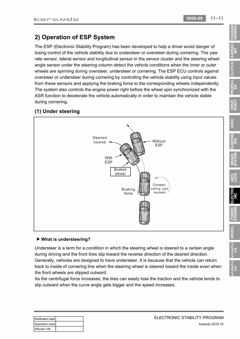
2) Operation of ESP SystemThe ESP (Electronic Stability Program) has been developed to help a driver avoid danger of losing control of the vehicle stability due to understeer or oversteer during cornering. The yaw rate sensor, lateral sensor and longitudinal sensor in the sensor cluster and the steering wheel angle sensor under the steering column detect the vehicle conditions when the inner or outer wheels are spinning during oversteer, understeer or cornering. The ESP ECU controls against oversteer or understeer during cornering by controlling the vehicle stability using input values from these sensors and applying the braking force to the corresponding wheels independently. The system also controls the engine power right before the wheel spin synchronized with the ASR function to decelerate the vehicle automatically in order to maintain the vehicle stable during cornering.
(1) Under steering
What is understeering?▶
Understeer is a term for a condition in which the steering wheel is steered to a certain angle during driving and the front tires slip toward the reverse direction of the desired direction. Generally, vehicles are designed to have understeer. It is because that the vehicle can return back to inside of cornering line when the steering wheel is steered toward the inside even when the front wheels are slipped outward. As the centrifugal force increases, the tires can easily lose the traction and the vehicle tends to slip outward when the curve angle gets bigger and the speed increases.
11-12
korando 2010.10
0000-00
ELECTRONIC STABILITY PROGRAM
ESP controls during understeer▶
The ESP system recognizes the directional angle with the steering wheel angle sensor and senses the slipping route that occurs reversely against the vehicle cornering direction during understeer with the yaw rate sensor and lateral sensor. Then, the ESP system applies the braking force to the rear inner wheel to compensate the yaw moment value. In this way, the vehicle does not lose its driving direction and the driver can steer the vehicle as intended.
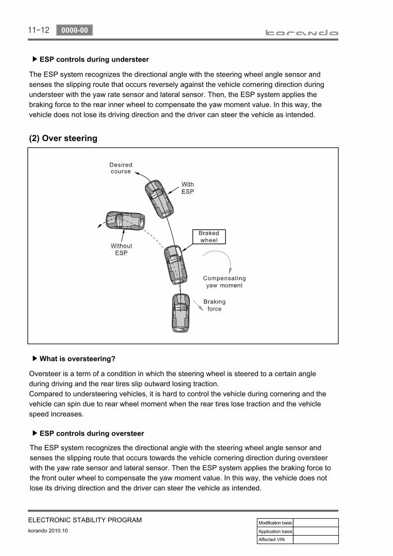
(2) Over steering
What is oversteering?▶
Oversteer is a term of a condition in which the steering wheel is steered to a certain angle during driving and the rear tires slip outward losing traction. Compared to understeering vehicles, it is hard to control the vehicle during cornering and the vehicle can spin due to rear wheel moment when the rear tires lose traction and the vehicle speed increases.
ESP controls during oversteer▶
The ESP system recognizes the directional angle with the steering wheel angle sensor and senses the slipping route that occurs towards the vehicle cornering direction during oversteer with the yaw rate sensor and lateral sensor. Then the ESP system applies the braking force to the front outer wheel to compensate the yaw moment value. In this way, the vehicle does not lose its driving direction and the driver can steer the vehicle as intended.
11-13
ELECTRONIC STABILITY PROGRAMkorando 2010.10
0000-00
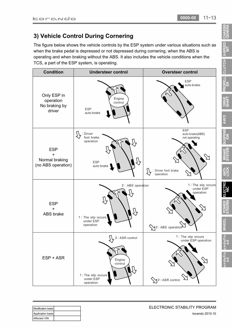
3) Vehicle Control During CorneringThe figure below shows the vehicle controls by the ESP system under various situations such as when the brake pedal is depressed or not depressed during cornering, when the ABS is operating and when braking without the ABS. It also includes the vehicle conditions when the TCS, a part of the ESP system, is operating.
Condition Understeer control Oversteer control
Only ESP in operation
No braking by driver
ESP+
Normal braking(no ABS operation)
ESP+
ABS brake
ESP + ASR

11-14
korando 2010.10
0000-00
ELECTRONIC STABILITY PROGRAM
4) HBA (Hydraulic Brake Assist System)
(1) Purpose HBA (Hydraulic Brake Assist) system helps in an emergency braking situation when the driver applies the brake fast, but not with sufficient pressure, which leads to dangerously long braking distance. ECU recognizes the attempt at full braking and transmits the signal calling for full brake pressure from the hydraulic booster. An inexperienced, elderly or physically weak driver may suffer from the accident by not fully pressing the brake pedal when hard braking is required under emergency. The HBA System increases the braking force under urgent situations to enhance the inputted braking force from the driver. Based on the fact that some drivers depress the brake pedal too soft even under when hard braking is necessary, the HECU system is a safety supplementary system that builds high braking force during initial braking according to pressure value of the brake pressure sensor and the pressure changes of the pressure sensor intervals. When the system is designed to apply high braking force when brake pedal is depressed softly by an elderly or physically weak driver, the vehicle will make abrupt stopping under normal braking situation due to high braking pressure at each wheels.
(2) OperationThe brake pressure value and the changed value of the pressure sensor are the conditions in which the HBA System operates. There are 2 pressure sensors under the master cylinder. When the ESP ECU system determines that emergency braking is present, the pump operates, the brake fluid in the master cylinder is sent to the pump and the braking pressure is delivered to the wheels via the inlet valves . If the drive depress the brake pedal slowly, the pressure change is not high. In this case, only the conventional brake system with booster is activated.
(3) Operating conditionsSensor pressure: over 40 barPressure changes: over 850 bar/secVehicle speed: over 30 km/h
---
11-15
ELECTRONIC STABILITY PROGRAMkorando 2010.10
0000-00
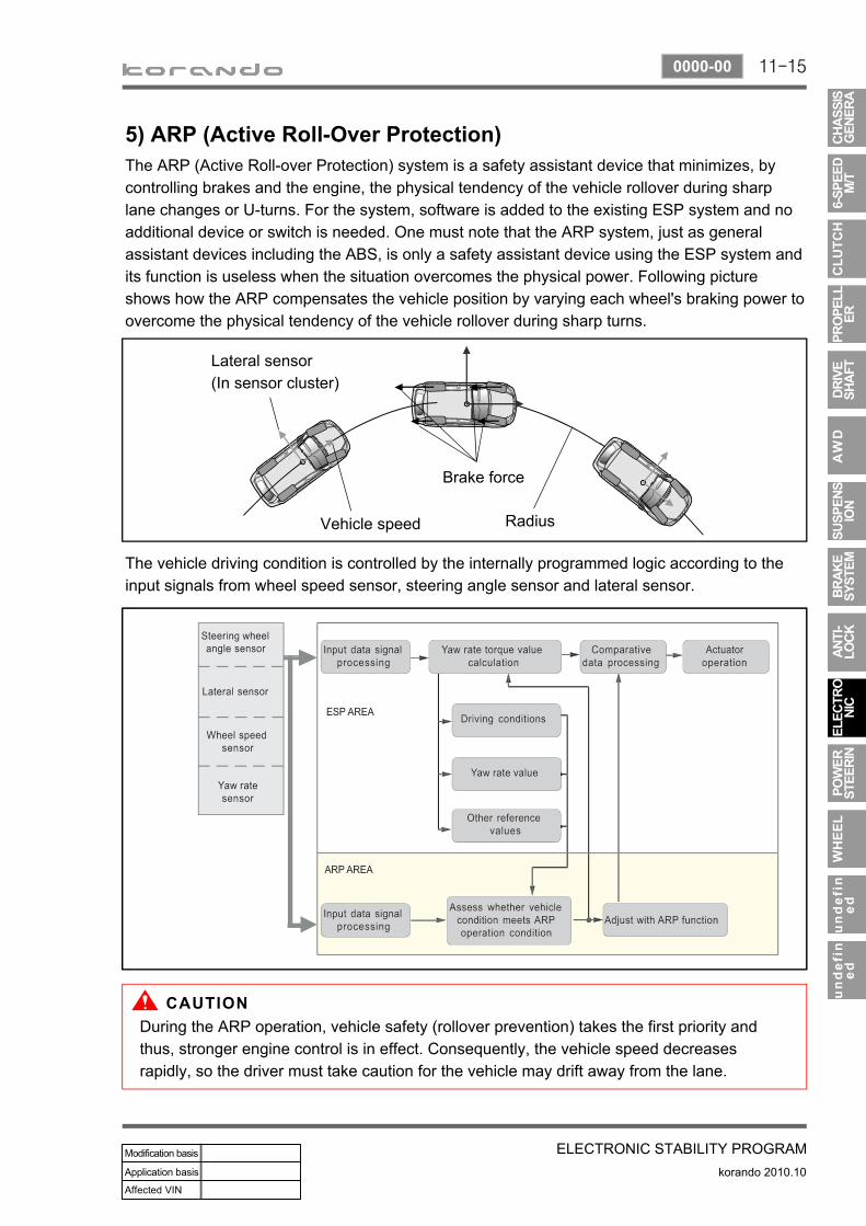
5) ARP (Active Roll-Over Protection)The ARP (Active Roll-over Protection) system is a safety assistant device that minimizes, by controlling brakes and the engine, the physical tendency of the vehicle rollover during sharp lane changes or U-turns. For the system, software is added to the existing ESP system and no additional device or switch is needed. One must note that the ARP system, just as general assistant devices including the ABS, is only a safety assistant device using the ESP system and its function is useless when the situation overcomes the physical power. Following picture shows how the ARP compensates the vehicle position by varying each wheel's braking power to overcome the physical tendency of the vehicle rollover during sharp turns.
Lateral sensor(In sensor cluster)
Vehicle speed
Brake force
Radius
The vehicle driving condition is controlled by the internally programmed logic according to the input signals from wheel speed sensor, steering angle sensor and lateral sensor.
During the ARP operation, vehicle safety (rollover prevention) takes the first priority and thus, stronger engine control is in effect. Consequently, the vehicle speed decreases rapidly, so the driver must take caution for the vehicle may drift away from the lane.
11-16
korando 2010.10
0000-00
ELECTRONIC STABILITY PROGRAM
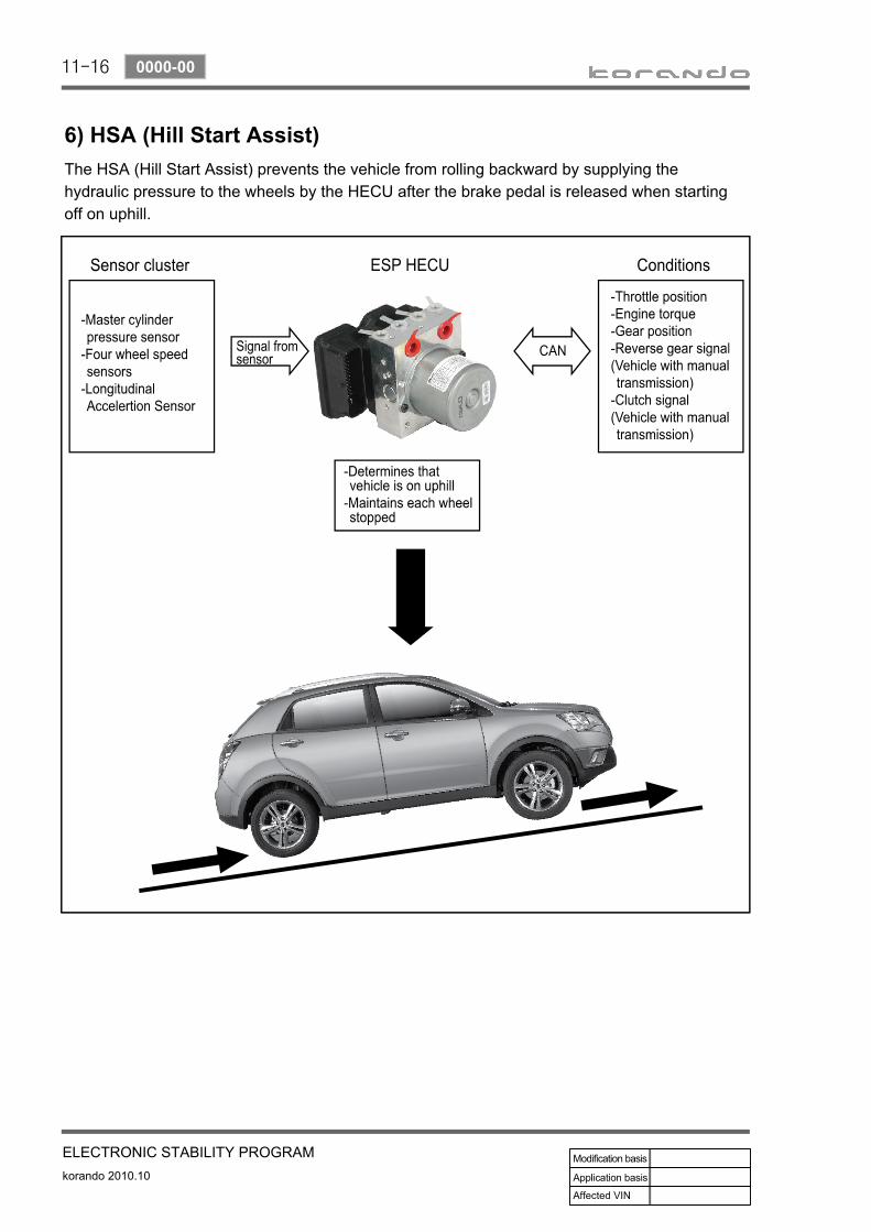
6) HSA (Hill Start Assist)The HSA (Hill Start Assist) prevents the vehicle from rolling backward by supplying the hydraulic pressure to the wheels by the HECU after the brake pedal is released when starting off on uphill.
11-17
ELECTRONIC STABILITY PROGRAMkorando 2010.10
0000-00
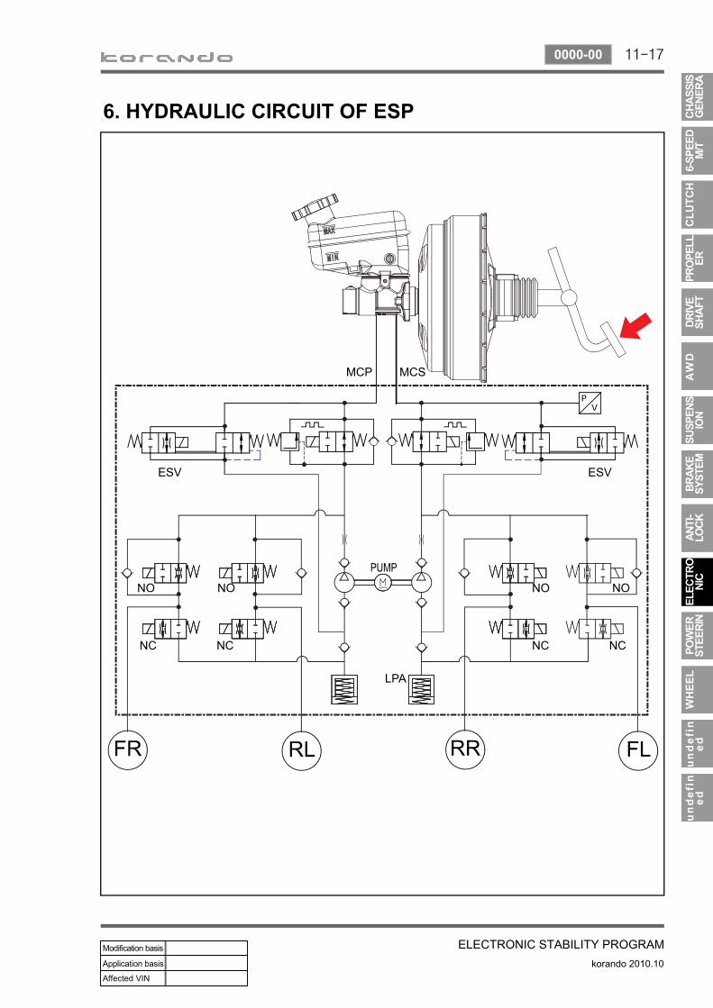
6. HYDRAULIC CIRCUIT OF ESP

11-18
korando 2010.10
0000-00
ELECTRONIC STABILITY PROGRAM
Circuit description▶
When compared to the vehicle equipped with ABS/EBD only, the internal hydraulic circuit has a normally-open separation valve and a shuttle valve in primary circuit and in secondary circuit. When the vehicle brakes are not applied during engine running or when applying the non-ABS operating brakes, the normally-open separation valve and the inlet valve are open, whereas the normally-closed shuttle valve and the outlet valve are closed. When the ESP system is operating, the normally-open separation valve will be closed by the solenoid valve operation and the hydraulic circuit will be established by the shuttle valve. Then, the inlet and outlet valves will be closed or open depending on the braking pressure RISE, HOLD or DUMP conditions.
Flashing warning lamp and warning sound during ESP operation▶
When the ESP operates while the vehicle is moving, the ESP warning lamp on the instrument panel flickers and the buzzer sounds at every 0.1 second. The ESP lamp operation is to inform a driver that the vehicle is extremely unstable. The ESP system is just a supplementary system for the vehicle and it cannot control the vehicle over the physical limit. Do not solely rely on the system but be advised to drive the vehicle safely.
Drive feeling during ESP operation▶
When the ESP system activates, the driving feeling can be different depending on vehicle driving conditions. For example, it will feel different when the ESP system is activated while the ABS is operated by depressing the brake pedal and when the ESP system is in control without the brake pedal depressed on the same curve. If the ESP system operates with the brake applied, the brake pressure will be increased on the corresponding wheel which already has braking pressure for the ESP controls. In other words, the ESP system would make the driver feel more abruptly braked compared to the situation that the braking pressure is applied to wheel which had no braking force.
Noise and vibration that driver senses during ESP operation▶
The ESP system may transfer noise and vibration to a driver due to the pressure changes caused by the motor and valve operations in a very short period of time. Extreme cornering will trigger the ESP operation and this will make the driver sense noise and vibration due to sudden brake application. Also, the ESP system controls the engine power. Therefore, the driver may notice the engine power decreases even when the accelerator pedal is depressed.
11-19
ELECTRONIC STABILITY PROGRAMkorando 2010.10
0000-00
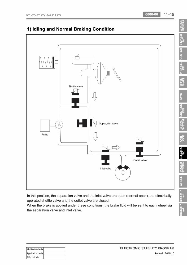
1) Idling and Normal Braking Condition
In this position, the separation valve and the inlet valve are open (normal open), the electrically operated shuttle valve and the outlet valve are closed.When the brake is applied under these conditions, the brake fluid will be sent to each wheel via the separation valve and inlet valve.

11-20
korando 2010.10
0000-00
ELECTRONIC STABILITY PROGRAM
2) DUMP (ESP is working) Mode
The pressure decreases just before the wheel speed drops and the wheels are locked. The inlet valve closes and the outlet valve opens as in the ABS HECU and the oil is gathered at the low pressure chamber while no additional oil is being supplied. Then the pump operates to allow fast oil drainage. The shuttle valve and the separation valve do not operate while decompression.

11-21
ELECTRONIC STABILITY PROGRAMkorando 2010.10
0000-00
3) HOLD (ESP is working) Mode
The Inlet valve and outlet valve will be closed to maintain the pressure in the hydraulic circuit applied at the wheels. By closing the valves, the hydraulic pressure at the wheels will not be lost or supplied any more. During ESP operation, the separation valve closes and only the shuttle valve at the pump opens.

11-22
korando 2010.10
0000-00
ELECTRONIC STABILITY PROGRAM
4) RISE (ESP is working) Mode
The shuttle valve and inlet valve will be open and the separation valve and outlet valve will be closed. Then, the pump is operated. When ESP operates while the ABS is operating, the pressure will be increased continuously until just before the corresponding wheel gets locked.

11-23
ELECTRONIC STABILITY PROGRAMkorando 2010.10
0000-00
5) Hydraulic Circuit of HBA
The above figure shows one front and one rear wheel and the same hydraulic circuit forms as in the ESP operation. When HECU recognizes that it is an emergency and it is required for hard braking, depending on the pressure value of the brake pressure sensor and pressure changes caused by the pressure sensor timing, it operates the pump immediately to apply the brake pressure at the wheels. Then, the pressure in the pump increases until just before the corresponding wheel gets locked. The motor still keeps rotating and the outlet valve and the separation valve will stay closed. When the wheel starts to lock, the HBA function cancels and switches to ABS operation.

11-24
korando 2010.10
0000-00
ELECTRONIC STABILITY PROGRAM
7. CIRCUIT DIAGRAMWheel speed sensor, Stop lamp switch, Self diagnostic connector, Warning lamp (ABS/ESP)
▶