1 software engineering: a practitioner’s approach, 6/e chapter 8: 8.1-8.6 analysis modeling...
TRANSCRIPT

1
Software Engineering: A Practitioner’s Software Engineering: A Practitioner’s Approach, 6/eApproach, 6/e
Chapter 8: 8.1-8.6Chapter 8: 8.1-8.6Analysis ModelingAnalysis Modeling
copyright © 1996, 2001, 2005
R.S. Pressman & Associates, Inc.
For University Use OnlyMay be reproduced ONLY for student use at the university level
when used in conjunction with Software Engineering: A Practitioner's Approach.Any other reproduction or use is expressly prohibited.

2
Requirements AnalysisRequirements Analysis
Requirements analysis Requirements analysis specifies software’s operational characteristicsspecifies software’s operational characteristics indicates software's interface with other system elements indicates software's interface with other system elements establishes constraints that software must meetestablishes constraints that software must meet
Requirements analysis allows the software engineer Requirements analysis allows the software engineer (called an (called an analystanalyst or or modelermodeler in this role) to: in this role) to: elaborate on basic requirements established during earlier elaborate on basic requirements established during earlier
requirement engineering tasksrequirement engineering tasks build models that depict user scenarios, functional activities, build models that depict user scenarios, functional activities,
problem classes and their relationships, system and class problem classes and their relationships, system and class behavior, and the flow of data as it is transformed. behavior, and the flow of data as it is transformed.

3
A BridgeA Bridge
system description
analysis model
design model
4
Rules of ThumbRules of Thumb The model should focus on requirements that are visible The model should focus on requirements that are visible
within the problem or business domain. The level of within the problem or business domain. The level of abstraction should be relatively high. abstraction should be relatively high.
Each element of the analysis model should add to an Each element of the analysis model should add to an overall understanding of software requirements and overall understanding of software requirements and provide insight into the information domain, function and provide insight into the information domain, function and behavior of the system.behavior of the system.
Delay consideration of infrastructure and other non-Delay consideration of infrastructure and other non-functional models until design. functional models until design.
Minimize coupling throughout the system. Minimize coupling throughout the system. Be certain that the analysis model provides value to all Be certain that the analysis model provides value to all
stakeholders. stakeholders. Keep the model as simple as it can be. Keep the model as simple as it can be.

5
Domain AnalysisDomain Analysis
Software domain analysis is the identification, Software domain analysis is the identification, analysis, and specification of common analysis, and specification of common requirements from a specific application requirements from a specific application domain, typically for reuse on multiple projects domain, typically for reuse on multiple projects within that application domain . . . [Object-within that application domain . . . [Object-oriented domain analysis is] the identification, oriented domain analysis is] the identification, analysis, and specification of common, reusable analysis, and specification of common, reusable capabilities within a specific application domain, capabilities within a specific application domain, in terms of common objects, classes, in terms of common objects, classes, subassemblies, and frameworks . . .subassemblies, and frameworks . . .Donald Firesmith

6
Domain AnalysisDomain Analysis Define the domain to be investigated.Define the domain to be investigated. Collect a representative sample of Collect a representative sample of
applications in the domain.applications in the domain. Analyze each application in the sample.Analyze each application in the sample. Develop an analysis model for the objects. Develop an analysis model for the objects.

7
Data ModelingData Modeling
examines data objects examines data objects independently of processingindependently of processing
focuses attention on the data focuses attention on the data domaindomain
creates a model at the customer’s creates a model at the customer’s level of abstractionlevel of abstraction
indicates how data objects relate to indicates how data objects relate to one anotherone another

8
What is a Data Object?What is a Data Object?
ObjectObject——something that is described by a setsomething that is described by a setof attributes (data items) and that will be of attributes (data items) and that will be manipulated within the software (system)manipulated within the software (system)
each each instanceinstanceof an object (e.g., a book) of an object (e.g., a book) can be identified uniquely (e.g., ISBN #) can be identified uniquely (e.g., ISBN #)
each plays a necessary role in the systemeach plays a necessary role in the systemi.e., the system could not function without i.e., the system could not function without access to instances of the objectaccess to instances of the objecteach is described by attributes that are each is described by attributes that are
themselves data itemsthemselves data items

9
Typical ObjectsTypical Objects
external entitiesexternal entities (printer, user, sensor)(printer, user, sensor)thingsthings (e.g, reports, displays, signals) (e.g, reports, displays, signals)
occurrences or eventsoccurrences or events (e.g., interrupt, alarm)(e.g., interrupt, alarm)rolesroles (e.g., manager, engineer, salesperson)(e.g., manager, engineer, salesperson)
organizational unitsorganizational units (e.g., division, team)(e.g., division, team)placesplaces (e.g., manufacturing floor) (e.g., manufacturing floor)
structuresstructures (e.g., employee record)(e.g., employee record)

10
Data Objects and Data Objects and AttributesAttributes
A data object contains a set of A data object contains a set of attributes that act as an aspect, attributes that act as an aspect, quality, characteristic, or descriptor of quality, characteristic, or descriptor of the objectthe objectobject: automobileobject: automobile
attributes:attributes: makemake modelmodel body typebody type priceprice options codeoptions code
11
What is a Relationship?What is a Relationship?
relationshiprelationship——indicates “connectedness”; indicates “connectedness”; a "fact" that must be "remembered" a "fact" that must be "remembered" by the system and cannot or is not computed by the system and cannot or is not computed or derived mechanicallyor derived mechanically
several instances of a relationship several instances of a relationship can existcan exist
objects can be related in many objects can be related in many different waysdifferent ways
12
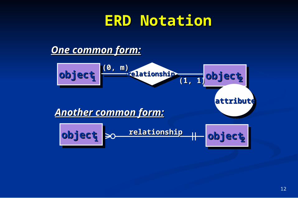
ERD NotationERD Notation
(0, m) (1, 1)
objectobject objectobjectrelationshiprelationship11 22
One common form:One common form:
(0, m)(0, m)
(1, 1)(1, 1)
objectobject11 objectobject22relationshiprelationship
Another common form:Another common form:attributeattribute

13
Building an ERDBuilding an ERD
Level 1—model all data objects (entities) and Level 1—model all data objects (entities) and their “connections” to one anothertheir “connections” to one another
Level 2—model all entities and relationshipsLevel 2—model all entities and relationships Level 3—model all entities, relationships, Level 3—model all entities, relationships,
and the attributes that provide further depthand the attributes that provide further depth

14
The ERD: An ExampleThe ERD: An Example
(1,1)(1,1) (1,m)(1,m)placesplacesCustomerCustomer
requestrequestfor servicefor service
generatesgenerates (1,n)(1,n)
(1,1)(1,1)
workworkorderorder
workworktaskstasks
materialsmaterials
consistsconsistsofof
listslists
(1,1)(1,1)(1,w)(1,w)
(1,1)
(1,i)(1,i)
selectedselectedfromfrom
standardstandardtask tabletask table
(1,w)(1,w)
(1,1)(1,1)

15
Object-Oriented ConceptsObject-Oriented Concepts
Must be understood to apply class-based Must be understood to apply class-based elements of the analysis modelelements of the analysis model
Key concepts:Key concepts: Classes and objectsClasses and objects Attributes and operationsAttributes and operations Encapsulation and instantiationEncapsulation and instantiation InheritanceInheritance

16
ClassClasseses• object-oriented thinking begins with object-oriented thinking begins with
the definition of a the definition of a class,class, often often defined as:defined as:– templatetemplate– generalized descriptiongeneralized description– “ “blueprint” ... describing a collection of blueprint” ... describing a collection of
similar itemssimilar items• a a metaclassmetaclass (also called a (also called a superclasssuperclass) )
establishes a hierarchy of classesestablishes a hierarchy of classes• once a class of items is defined, a once a class of items is defined, a
specific instance of the class can be specific instance of the class can be identified identified

17
Building a Building a ClassClass
class name
attributes:
operations:
attributes:
operations
18
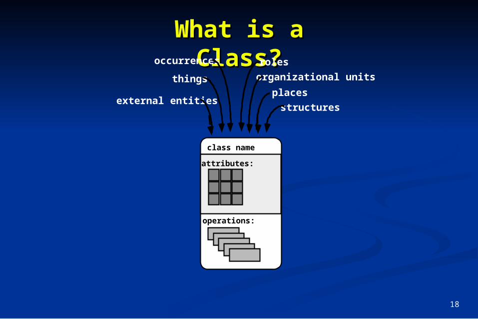
What is a What is a Class?Class?
external entities
things
occurrences roles
organizational units
places
structures
class name
attributes:
operations:

19
Encapsulation/Encapsulation/HidingHidingThe object encapsulates
both data and the logicalprocedures required tomanipulate the data
Achieves “information hiding”
method # 1
data
method # 2
method # 4
method # 5
method # 6
method # 3

20
Class Class HierarchyHierarchy
ChairTable Desk ”Chable"
instances of Chair
PieceOfFurniture (superclass)
subclasses of the

21
MethodsMethods(a.k.a. Operations, (a.k.a. Operations,
Services)Services)An executable procedure that is encapsulated in a class and is designed to operate on one or more data attributes that are defined as part of the class.A method is invoked via message passing.

22
Scenario-Based ModelingScenario-Based Modeling
““[Use-cases] are simply an aid to defining what [Use-cases] are simply an aid to defining what exists outside the system (actors) and what exists outside the system (actors) and what should be performed by the system (use-cases).” should be performed by the system (use-cases).” Ivar JacobsonIvar Jacobson
(1) What should we write about?(1) What should we write about?
(2) How much should we write about it?(2) How much should we write about it?
(3) How detailed should we make our description? (3) How detailed should we make our description?
(4) How should we organize the description?(4) How should we organize the description?

23
Use-Use-CasesCases
a scenario that describes a “thread of a scenario that describes a “thread of usage” for a systemusage” for a system
actorsactors represent roles people or devices represent roles people or devices play as the system functionsplay as the system functions
usersusers can play a number of different roles can play a number of different roles for a given scenariofor a given scenario

24
Developing a Use-Developing a Use-CaseCase What are the main tasks or functions that are performed What are the main tasks or functions that are performed
by the actor?by the actor? What system information will the the actor acquire, What system information will the the actor acquire,
produce or change?produce or change? Will the actor have to inform the system about changes Will the actor have to inform the system about changes
in the external environment?in the external environment? What information does the actor desire from the system?What information does the actor desire from the system? Does the actor wish to be informed about unexpected Does the actor wish to be informed about unexpected
changes?changes?

25
Use-Case DiagramUse-Case Diagram
homeowner
Access camera surveillance via the
Internet
Configure SafeHome system parameters
Set alarm
cameras
SafeHome

26
Activity DiagramActivity DiagramSupplements the use-case by providing a diagrammatic Supplements the use-case by providing a diagrammatic representation of procedural flowrepresentation of procedural flow
enter password and user ID
select major function
valid passwords/ ID
prompt for reentry
invalid passwords/ ID
input tries remain
no inputtries remain
select surveillance
other functions may also be
selected
thumbnail views select a specif ic camera
select camera icon
prompt for another view
select specific camera - thumbnails
exit this function see another camera
view camera output in labelled window

27
Swimlane DiagramsSwimlane DiagramsAllows the modeler to represent the flow of activities described by the use-case Allows the modeler to represent the flow of activities described by the use-case and at the same time indicate which actor (if there are multiple actors involved and at the same time indicate which actor (if there are multiple actors involved in a specific use-case) or analysis class has responsibility for the action in a specific use-case) or analysis class has responsibility for the action described by an activity rectangledescribed by an activity rectangle
enter password and user ID
select major function
valid passwords/ ID
prompt for reentry
invalidpasswords/ ID
input tries
remain
no input
tries remain
select surveillance
other functions may also be
selected
thumbnail views select a specif ic camera
select camera icon
generate video output
select specific camera - thumbnails
exit thisfunction
see
anothercamera
homeowner c amera int erf ac e
prompt foranother view
view camera output in labelled window

28
Flow-Oriented Flow-Oriented ModelingModeling
Represents how data objects are transformed at Represents how data objects are transformed at they move through the systemthey move through the system
A A data flow diagram (DFD)data flow diagram (DFD) is the diagrammatic is the diagrammatic form that is usedform that is used
Considered by many to be an ‘old school’ Considered by many to be an ‘old school’ approach, flow-oriented modeling continues to approach, flow-oriented modeling continues to provide a view of the system that is unique—it provide a view of the system that is unique—it should be used to supplement other analysis should be used to supplement other analysis model elementsmodel elements

29
The Flow ModelThe Flow ModelEvery computer-based system is an Every computer-based system is an information transform ....information transform ....
computercomputerbasedbased
systemsysteminputinput outputoutput

30
Flow Modeling NotationFlow Modeling Notation
external entityexternal entity
processprocess
data flowdata flow
data storedata store

31
External EntityExternal Entity
A producer or consumer of dataA producer or consumer of data
Examples: a person, a device, a sensorExamples: a person, a device, a sensor
Another example: computer-basedAnother example: computer-basedsystemsystem
Data must always originate somewhereData must always originate somewhereand must always be sent to somethingand must always be sent to something

32
ProcessProcess
A data transformer (changes inputA data transformer (changes inputto output)to output)
Examples: compute taxes, determine area,Examples: compute taxes, determine area,format report, display graph format report, display graph
Data must always be processed in some Data must always be processed in some way to achieve system functionway to achieve system function

33
Data FlowData Flow
Data flows through a system, beginningData flows through a system, beginningas input and be transformed into output.as input and be transformed into output.
computecomputetriangle triangle
areaarea
basebase
heightheight
areaarea

34
Data StoresData Stores
DataData is often stored for later use.is often stored for later use.
look-uplook-upsensorsensor
datadata
sensor #sensor #
report requiredreport required
sensor #, type, sensor #, type, location, agelocation, age
sensor datasensor data
sensor numbersensor number
type, type, location, agelocation, age
35
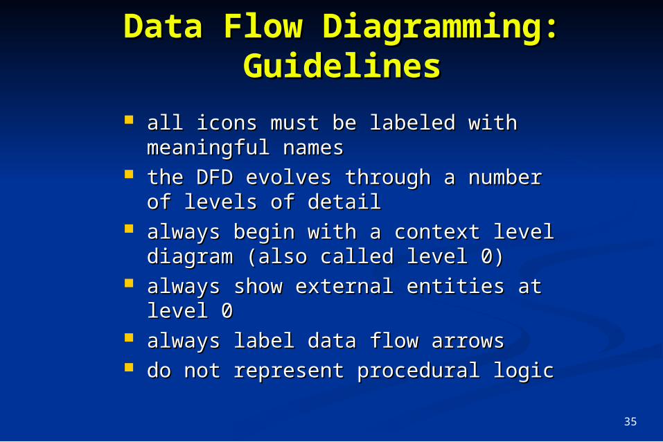
Data Flow Diagramming:Data Flow Diagramming:GuidelinesGuidelines
all icons must be labeled with all icons must be labeled with meaningful namesmeaningful names
the DFD evolves through a number of the DFD evolves through a number of levels of detaillevels of detail
always begin with a context level always begin with a context level diagram (also called level 0)diagram (also called level 0)
always show external entities at level always show external entities at level 00
always label data flow arrowsalways label data flow arrows do not represent procedural logicdo not represent procedural logic

36
Constructing a DFD—IConstructing a DFD—I
review the data model to isolate data review the data model to isolate data objects and use a grammatical parse to objects and use a grammatical parse to determine “operations”determine “operations”
determine external entities (producers determine external entities (producers and consumers of data)and consumers of data)
create a level 0 DFDcreate a level 0 DFD

37
Level 0 DFD ExampleLevel 0 DFD Example
useruserprocessing processing
requestrequest
videovideosourcesource NTSCNTSC
video signalvideo signal
digitaldigitalvideovideo
processorprocessor
requestedrequestedvideovideosignalsignal
monitormonitor

38
Constructing a DFD—IIConstructing a DFD—II
write a narrative describing the write a narrative describing the transformtransform
parse to determine next level parse to determine next level transformstransforms
““balance” the flow to maintain data balance” the flow to maintain data flow continuityflow continuity
develop a level 1 DFDdevelop a level 1 DFD use a 1:5 (approx.) expansion ratiouse a 1:5 (approx.) expansion ratio
39
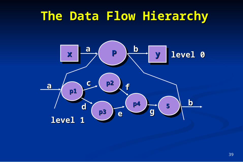
The Data Flow HierarchyThe Data Flow Hierarchy
PPaa bbxx yy
p1p1p2p2
p3p3p4p4 55
aa
bb
cc
ddee
ff
gg
level 0level 0
level 1level 1

40
Flow Modeling NotesFlow Modeling Notes
each bubble is refined until it does each bubble is refined until it does just one thingjust one thing
the expansion ratio decreases as the the expansion ratio decreases as the number of levels increasenumber of levels increase
most systems require between 3 and most systems require between 3 and 7 levels for an adequate flow model7 levels for an adequate flow model
a single data flow item (arrow) may a single data flow item (arrow) may be expanded as levels increase (data be expanded as levels increase (data dictionary provides information)dictionary provides information)

41
Process Specification Process Specification (PSPEC)(PSPEC)
PSPECPSPEC
narrativenarrativepseudocode (PDL)pseudocode (PDL)
equationsequationstablestables
diagrams and/or chartsdiagrams and/or charts
bubblebubble

42
Maps intoMaps into
DFDs: A Look AheadDFDs: A Look Ahead
analysis modelanalysis model
design modeldesign model

43
Control Flow DiagramsControl Flow Diagrams
Represents “Represents “eventsevents” and the processes that ” and the processes that manage eventsmanage events
An “event” is a Boolean condition that can be An “event” is a Boolean condition that can be ascertained by:ascertained by:
listing all sensors that are "read" by the software.listing all sensors that are "read" by the software. listing all interrupt conditions.listing all interrupt conditions. listing all "switches" that are actuated by an operator.listing all "switches" that are actuated by an operator. listing all data conditions.listing all data conditions. recalling the noun/verb parse that was applied to the recalling the noun/verb parse that was applied to the
processing narrative, review all "control items" as possible processing narrative, review all "control items" as possible CSPEC inputs/outputs.CSPEC inputs/outputs.

44
The Control The Control ModelModelthe control flow diagram is "superimposed" on the DFD the control flow diagram is "superimposed" on the DFD
and shows events that control the processes noted in and shows events that control the processes noted in the DFDthe DFD
control flows—events and control items—are noted by control flows—events and control items—are noted by dashed arrowsdashed arrows
a vertical bar implies an input to or output from a control a vertical bar implies an input to or output from a control spec (CSPEC) — a separate specification that spec (CSPEC) — a separate specification that describes how control is handleddescribes how control is handled
a dashed arrow entering a vertical bar is an input to the a dashed arrow entering a vertical bar is an input to the CSPECCSPEC
a dashed arrow leaving a process implies a data a dashed arrow leaving a process implies a data conditioncondition
a dashed arrow entering a process implies a control a dashed arrow entering a process implies a control input read directly by the processinput read directly by the process
control flows do not physically activate/deactivate the control flows do not physically activate/deactivate the processes—this is done via the CSPECprocesses—this is done via the CSPEC

45
Control Flow Control Flow DiagramDiagram
readoperator
input
createuser
displaysperformproblem diagnosis
reloadprocess
managecopying
beeper on/off
start
copies done
display panel enabled
full
problem light
empty
jammed

46
Control Specification Control Specification (CSPEC)(CSPEC)
The CSPEC can be:The CSPEC can be:
state diagram state diagram (sequential spec)(sequential spec)
state transition tablestate transition table
decision tables decision tables
activation tablesactivation tables
combinatorial speccombinatorial spec

47
Guidelines for Building a Guidelines for Building a CSPECCSPEClist all sensors that are "read" by the softwarelist all sensors that are "read" by the software
list all interrupt conditionslist all interrupt conditions
list all "switches" that are actuated by the operatorlist all "switches" that are actuated by the operator
list all data conditionslist all data conditions
recalling the noun-verb parse that was applied to therecalling the noun-verb parse that was applied to thesoftware statement of scope, review all "control items"software statement of scope, review all "control items"
as possible CSPEC inputs/outputsas possible CSPEC inputs/outputs
describe the behavior of a system by identifying its describe the behavior of a system by identifying its states; identify how each state is reach and defines states; identify how each state is reach and defines
the transitions between statesthe transitions between states
focus on possible omissions ... a very common error in focus on possible omissions ... a very common error in specifying control, e.g., ask: "Is there any other way I specifying control, e.g., ask: "Is there any other way I can get to this state or exit from it?"can get to this state or exit from it?"