1 site master plan 2) site master plan. 2 site master planning planning rationale serious investment...
TRANSCRIPT
1
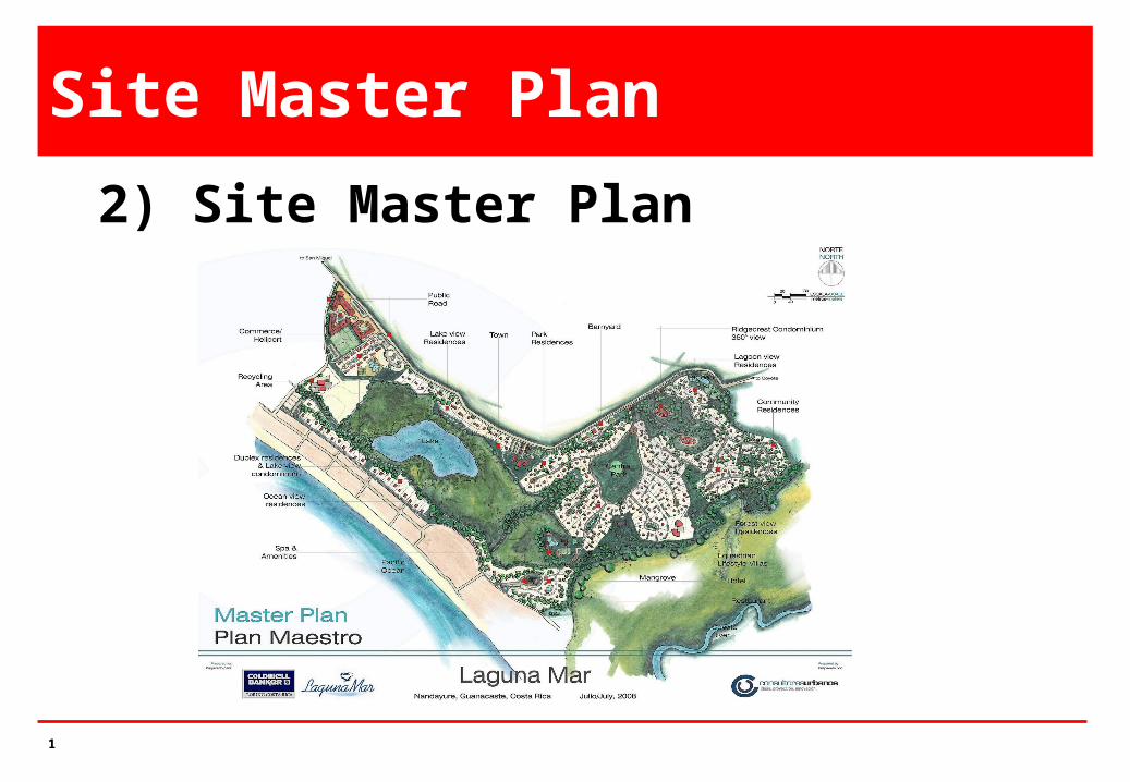
Site Master Plan
2) Site Master Plan
2
Site Master Planning
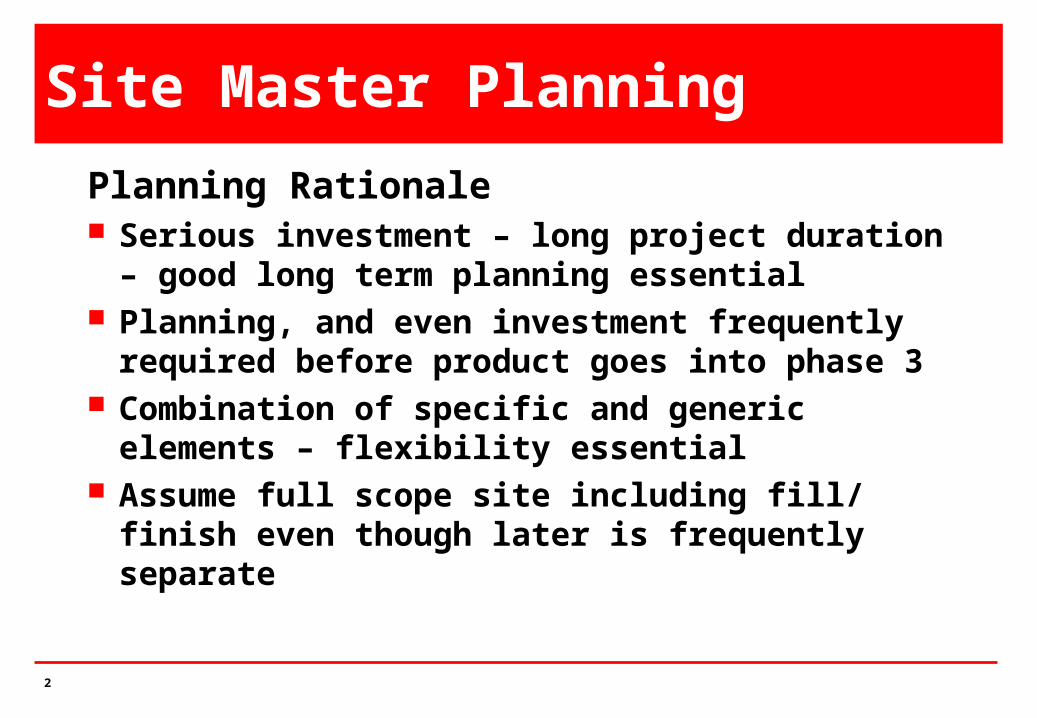
Planning Rationale Serious investment – long project duration – good long
term planning essential Planning, and even investment frequently required
before product goes into phase 3 Combination of specific and generic elements –
flexibility essential Assume full scope site including fill/ finish even though
later is frequently separate
3
Site Master Planning
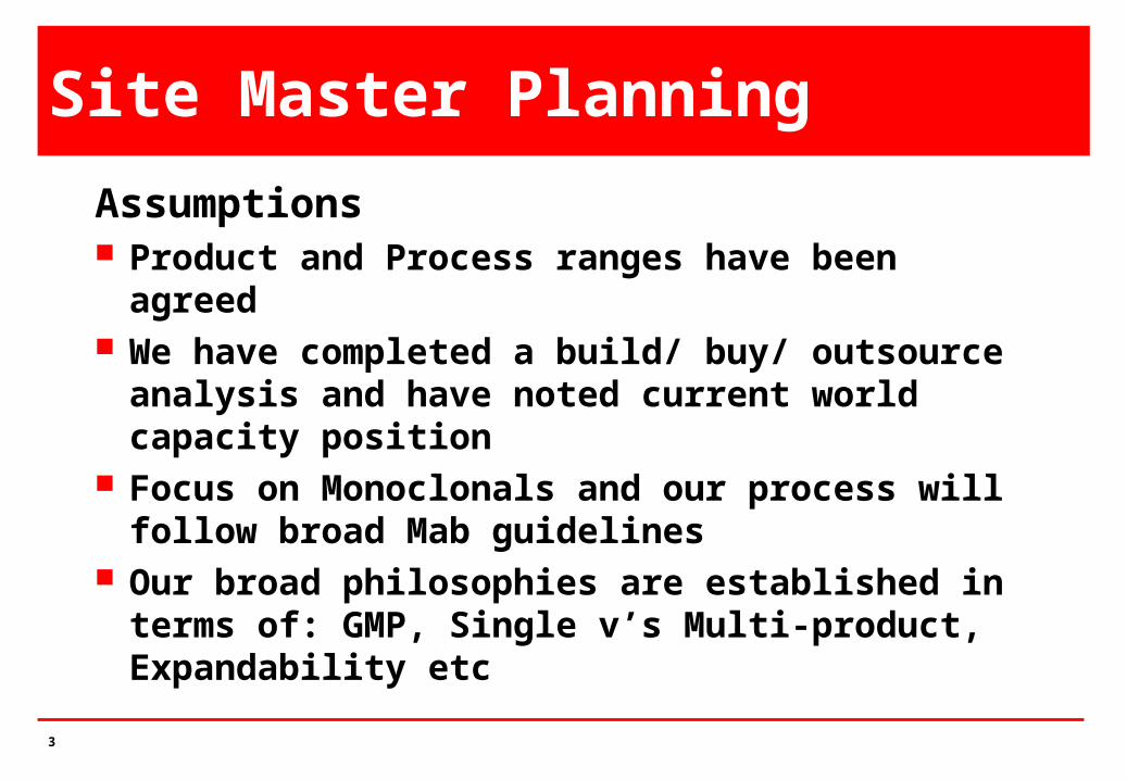
Assumptions Product and Process ranges have been agreed We have completed a build/ buy/ outsource analysis and
have noted current world capacity position Focus on Monoclonals and our process will follow broad
Mab guidelines Our broad philosophies are established in terms of:
GMP, Single v’s Multi-product, Expandability etc

4
Site Master Planning
Prerequisites Defined product characteristics Broad product demand parameters e.g. dose, patients
population etc Our market potential and penetration Broad process parameters Location philosophy Scope of investment on our site Site selection is nor a prerequisite for master planning
5
Site Master PlanningSite Scope Filling process and process utilities are core, usually in
single building Site usually includes process development, QA, QC,
warehouse, utilities, personnel facilities and technical management are needed
Fill finish (stages from bulk to dose form) are optional as are packaging and distribution
R&D, high level admin, finance, sales, etc are optional. Decision between ‘flagship facility’ and ‘lean, mean’ functional unit’ is essential early

6
Site Master Planning
Flexibility, Expandability, Future Proofing Key decisions are needed here – must be a cap! Define how much to install, how much to provide space
for, how much to service for? Philosophy on expandability, modularity, flexibility is
needed Define modularity – can range from slotting in a serviced
vessel to stand alone modular segments These decisions are fundamental, they can determine
the success or failure of the facility and must be in the context of 5 years in the future
7
Site Master Planning
Determine Site Requirements Sizing is based on output requirements. These derive
from dose x patient population and this applies to all facility levels (pilot, chemical, full scale)
Dose may be in vials, pre-filled syringes or other forms. Main form is lyophilised product in vials.
Separate logistics apply to sizing fill/ finish facility including formulation, bulk preparation, filling, lyophilization
8
Site Master Planning
Sizing & Shaping SMP is a collection of ‘boxes’ of varying size and shape
arranged in a functional, orderly and aseptically pleasing configuration
Sizing individual boxes requires analysis of the process requirements, sizing and arranging the equipment and services and configuring the internal workings for optimal personnel and material movement
Arranging the boxes needs an analysis of inter box movements and requirements for adjacency, closeness etc. Expansion philosophy is applied here
9
Site Master Planning
Broad Rules Minimise process transfers – address CIP considerations Recognise basic contiguity needs e.g. airlocks, gowning areas,
autoclaves, sterilizers vs protected core All material movements should be under cover (link corridors) HVAC plant rooms should be above classified areas – minimise
duct runs Buffer Prep and clean utilities to be adjacent to process areas Design from process core outwards and from output
requirements backwards

10
Site Master Planning
Configuration Philosophy Various layers are placed around production core –
based on proximity requirements Layers Adjoining Adjacent in same building Adjacent – linked by corridor Reasonably close – preferably covered access Remote
11
Site Master Planning
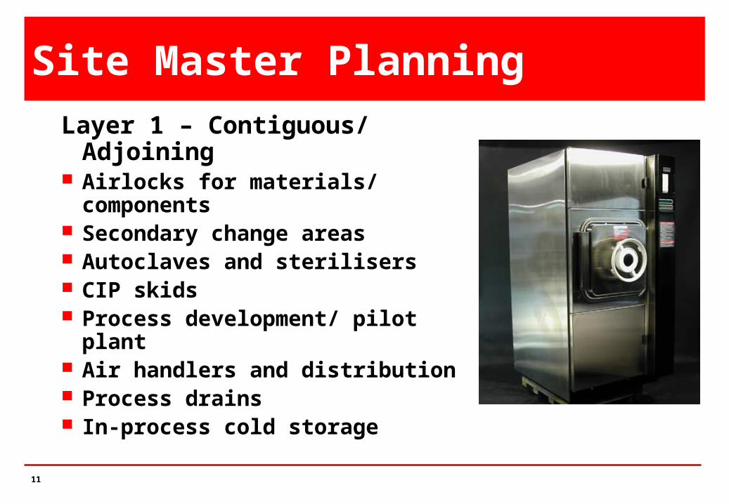
Layer 1 – Contiguous/ Adjoining Airlocks for materials/ components Secondary change areas Autoclaves and sterilisers CIP skids Process development/ pilot plant Air handlers and distribution Process drains In-process cold storage
12
Site Master Planning
Layer 2 – Same Building Clean utilities Buffer Preparation QA In-Process Lab Some personnel facilities on large site
13
Site Master Planning
Layer 3 – Adjacent Warehouse – separate linked
building Cold Store – Central Primary change for operators Maintenance workshop Cafeteria
14
Site Master Planning
Layer 4 - Near - Preferably Linked QC labs Engineering HR Administration Security EHS
15
Site Master Planning
Layer 5 – Remote or Distributed Utilities - general - steam, comp air,
potable water, chilling, fire water Effluent treating Fire water storage and pumping Tank farms Car parks / roads Gas storage
16
Site Master PlanningConfiguration Options Single Building – most economical but not good option
for large scale – limits expansion and mixes incompatible operations
Spin link corridor – probably ideal – buildings attached on 2 sides – can extend length and travel distances if expansion space is required
Rectangular loop link – also good – again can limit expansion but reduces some travel distances
Radial – good concept but impractical for implementation
17
Site Master Planning
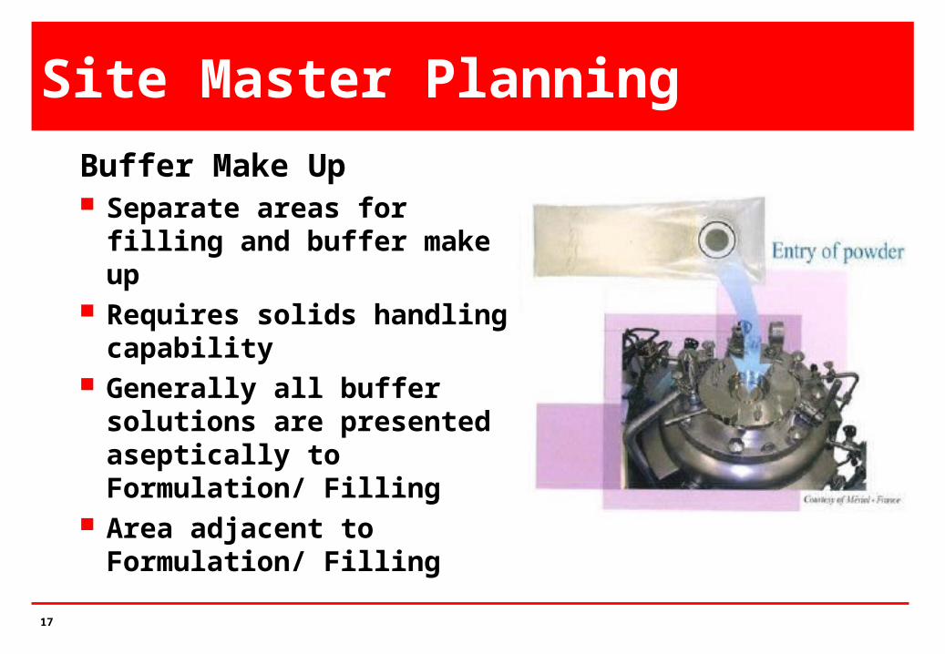
Buffer Make Up Separate areas for filling and
buffer make up Requires solids handling
capability Generally all buffer solutions
are presented aseptically to Formulation/ Filling
Area adjacent to Formulation/ Filling
18
Site Master Planning
Other Considerations Chilled Vessels for storage Intermediate cold storage Possible separate air handling systems Separate entry and exit facilities for materials and
personnel Decontamination of exiting clothing and equipment Later stages require aseptic handing and freezing
facilities
19
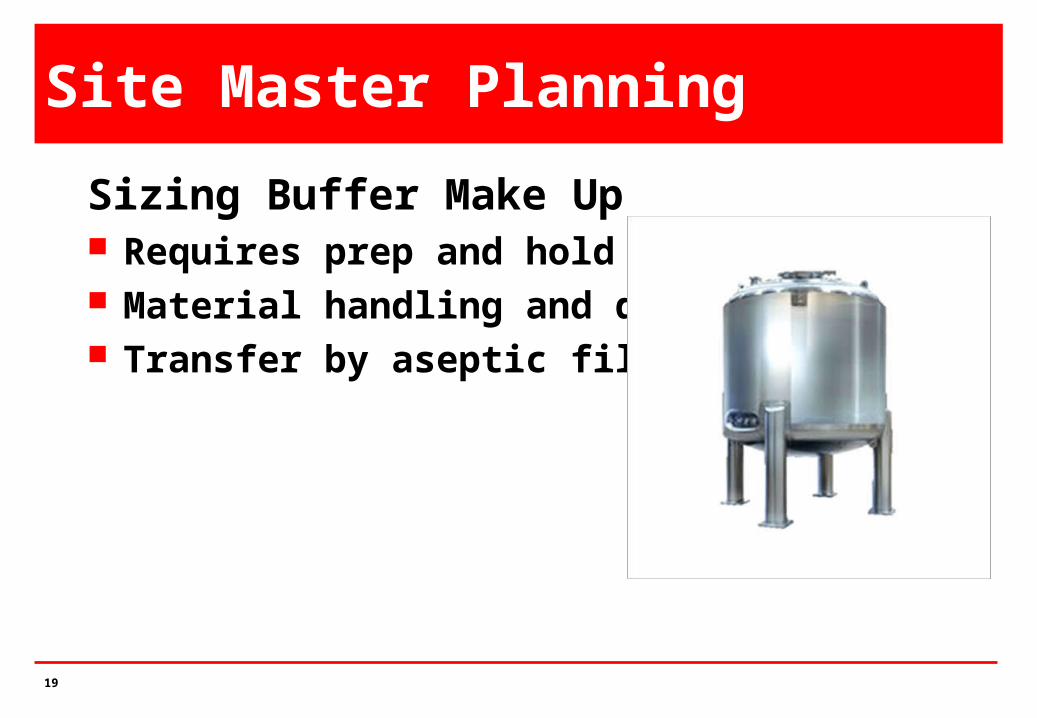
Site Master Planning
Sizing Buffer Make Up Requires prep and hold vessels Material handling and dust control Transfer by aseptic filtration

20
Site Master Planning
Sizing Process Utilities WFI requirements calculated on flows demands and
minimum circulation rates Storage vessels can be 10-20m3 – required balanced
calculation between storage and generation CIP demands determine capacities – high instant flow
rates Clean Steam based on max SIP load – usually empty
vessel – made from clean steam Clean gases based on process demands and some
transfers – all filtered
21
Site Master Planning
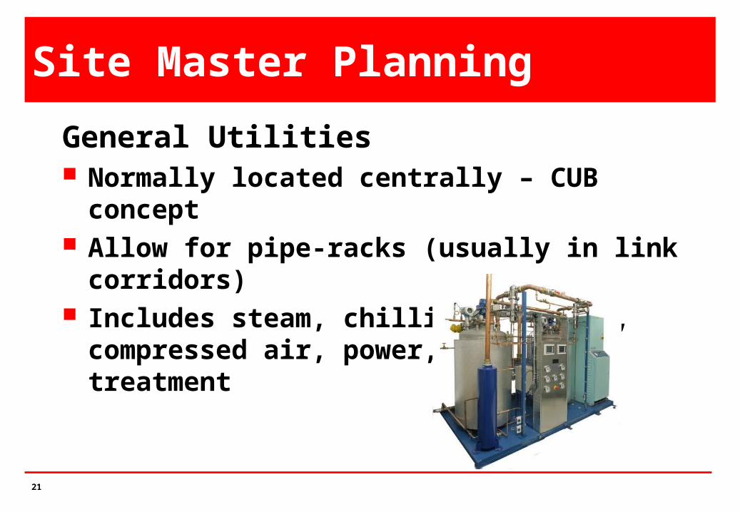
General Utilities Normally located centrally – CUB concept Allow for pipe-racks (usually in link corridors) Includes steam, chilling, cooling, compressed air, power,
effluent treatment
22
Site Master Planning
Utilities Sizing – Ranges Steam 40-60 tons/ hr @ 0 bar Chilling 20-30 MW Cooling 40-60 MW Compressed Air 4,000-6,000 Nm3 / hr Divide all into modules – min 3 equal sized units Power 20-30 MVA – Supply at
H.T.
23
Site Master Planning
Building Sizes - Ranges Sizing based on previous slides – boxes must be sized before
being arranged Multi-floor arrangements more economical within reason In all cases, top floor for plant with prospect of additional plant
space on 1 side Crude sizes for 100,000L facility approx, 60,000 – 80,000 m2
Bulk Production/ DSP 20,000m2 (3-4 floors) Fill/ Finish 10,000 – 15,000m2 (3 floors) Warehouse 10,000 m2 (1 floor @ 12m) CUB 5,000 – 10,000 m2 (1 floor) Development 9,000m2 (3 floors) Admin 5,000 – 10,000 m2 (3 floors)

24
Site Master Planning
Expansion Clear policy needed – otherwise high ‘fuzz’ potential Built space essential to avoid future disruption Adjacent space needed for all functions Constructability of expansion needs some study even at
GMP: stage

25
Technology Transfer
3) Technology Transfer

26
Overview
Introduction Critical GMP Drivers Tech Transfer Process Team Participation Tech Transfer Completion & Success
27
Technology Transfer Definition Transfer of all necessary information and support to
successfully manufacture and evaluate the transferred product, process or analytical test method, at the selected manufacturing site(s).
A successful transfer is a collaborative effort among cross-functional technology teams representing various site disciplines with communication as a cornerstone to that success.
28
What is Technology Transfer ? Product Technology Transfer
Business Considerations Shipping Considerations Material Availability Regulatory Considerations Strategic Facility considerations
Process/ Method Technology Transfer Specific Tests or Process Steps Specifications Process/ method development & validation Process related Facility Considerations

29
What is Technology Transfer ?Why conduct Technology Transfer?
Systematic approach Define responsibilities Ensure process/ method validation cGMP Drivers
Business Considerations ? Speed to Market Lower Cost Improved Customer Service Compliance Obligations
30
Critical GMP Drivers
No Specific Reference in 21CFR 210/211
31
Critical GMP Drivers
Indirect References in 21CFR 211 211.160 Subpart I, Laboratory Controls, General
Requirements 211.186 Subpart J, Records & Reports, Master
Production and Control Reports 211.110 Subpart F, Production and Process Controls,
Sampling and Testing of in-process materials and drug products.
211.100 Subpart F, Production and Process Controls, Written Procedures, Deviations

32
Critical GMP Drivers
Eudralex Vol 4 Chapter 7 – Contract Manufacture and Analysis 7.10 “A contract . . . specifies their respective
responsibilities relating to manufacture and control of the product. Technical aspects of the contract should be drawn up by persons suitably knowledgeable in pharmaceutical technology, analysis and Good Manufacturing Practice”
33
Critical GMP Drivers
Capture Critical GMP Drivers under Training
Subject Matter Experts (SMEs) Understand Science & Technology
Documentation Technical Documentation Package
Document Robustness Document consistency of control
Platform for Validation

34
Establishing a TT ProcessWho conducts Technology Transfer ?
Originating – Receiving sites
R&D / Commercial
Intra Company transfer
Site – Site or Internal
Transfer to External Business Partners
35
Technology Transfer RoadmapHow is Technology Transfer Conducted? Governance
Technology Development & Transfer (TD&T) TT Plan
Strategic Overview Experimental Outline and Validation Approach Accountability Table
Technical Documentation Package TT Report(s) Technical info & data generated in support of strategic plan

36
Roadmap - Tech Transfer Governance
What defines Governance ? TD&T Technology Transfer Agreement Quality Agreement Quality Policy Site Specific SOP(s)
Project Governance & Administrative
roles & responsibilities
Steering Committee TT Team Leader TT Team TT Team Members TT Sub Team Leader TT Sub Team(s) TT Sub Team Members
37
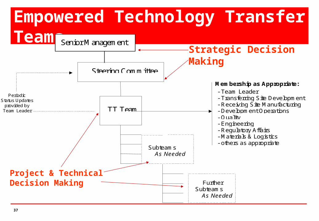
Empowered Technology Transfer Teams
Steering Committee Comm
TT Team
Subteams as As Needed
Membership as Appropriate: - Team Leader - Transferring Site Development - Receiving Site Manufacturing - Development Operations - Quality - Engineering - Regulatory Affairs - Materials & Logistics - others as appropriate
Periodic Status Updates
provided by Team Leader
Further Subteams
As Needed
Senior Management
Project & Technical Decision Making
Strategic DecisionMaking
38
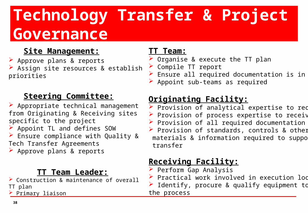
Site Management: Approve plans & reports Assign site resources & establish priorities
Steering Committee: Appropriate technical management from Originating & Receiving sites specific to the project Appoint TL and defines SOW Ensure compliance with Quality & Tech Transfer Agreements Approve plans & reports
TT Team Leader: Construction & maintenance of overall TT plan Primary liaison
TT Team: Organise & execute the TT plan Compile TT report Ensure all required documentation is in place Appoint sub-teams as required
Originating Facility: Provision of analytical expertise to receiving site Provision of process expertise to receiving site Provision of all required documentation Provision of standards, controls & other necessary materials & information required to support process transfer
Receiving Facility: Perform Gap Analysis Practical work involved in execution local gap closure Identify, procure & qualify equipment to supportthe process
Technology Transfer & Project Governance
39
Tech Transfer Execution Conduct Gap analysis & Identify Gaps between originating and
receiving facilities Process/Method Gaps
Conduct studies & generate data to support process / method
Information Gaps Gather / Source technical documents to support process / method
Facility Gaps Process change request through appropriate capital approval committee
Gap Analysis yields Work packages
Work packages comprise Accountability Tables
Action Items / task lists
40
Technology Transfer ExecutionDevelop TT Plan
Integrates action items from gap analysis with project timeline
Directs completion of Work Packages
from gap analysis
Integrates validation plans with
technology transfer
41
Technology Transfer PlanElements of the TT Plan
Strategic Overview Technical Descriptions Experimental Outline Validation Approach Success criteria Gates (accountability table) Training requirements Milestones & deliverables (schedule)
TT Structure implements the plan
42
Functional Team Participation – Critical Drivers Originating and Receiving Responsibilities Defined & Agreed up front.
Key Stake holder participation Open Communication Manage and Track Action Item closure on the TT Team to complete Gap Closure
Relationship Management (Team)
Excellent Management of Interfaces Establish relationships Manage Relationships Maintain Relationships
Use metrics to track TT progress On-time milestone tracking % Documents transferred / generated % Training Complete % Gaps closed

43
Tech Transfer Execution
When is Technology Transfer Complete?1. Phases
Learn Demonstrate Validate
2. Gates
Define transition to
next phase (readiness)Success
criteria
3. Deliverables
Process / Method
validated at receiving siteTechnology Transfer
Report Approved
44
Tech Transfer Execution
Phase I – Planning, Learning and Knowledge Capture Training of SMEs at originating site Integration with originating/receiving site schedules Transfer of Technical Documentation to receiving site
Phase II – Demonstration Batch Phase Transfer Execution at scale at receiving site Demonstration of robust process/method at receiving site
Phase III – Validation Batch Phase Validation of process at receiving site Production of commercial material
Phases of Technology Transfer
Gates are defined by the TT Plan

45
Functional Team Participation – Critical Drivers
Technology Transfer SME Model Key individuals on “assignment” for training at
originating site during learning phase Gather Data & Source Documentation Gain Expertise – learn “folklore” Train Operations (customer) Escort the process to Receiving site (Demo phase) Trouble-shoot & support start-up (Validation phase) Transition into Tech Services/Support (Comm phase)

46
One-Team cultureDO Invest in face to face meetings Spend time in partner facilities (walk
in their shoes) Assign specific SME partnerships Agree clear accountability and
decision-making Constantly adapt to schedule
opportunities Adopt formal, planned training
programs early
DON’T Escalate everything-keep the
team empowered Allow ‘us and them’ to
develop Keep critical information from
team members
47
Vehicles for Team SuccessPEOPLE Effort, commitment and expertise
from teams (and assignees where available)
Willingness to look for and exploit new ways to do things
Resources - effective hiring ramp-up providing staff when needed and allowing training to occur
Flexible working environment
ORGANISATION Focus on empowered teams
with clear goals, accountabilities and timelines
Effective integration and leveraging of external (business partner) staff
A Quality organisation that acts as a partner to get the job done
48
Key Business Processes Tech Transfer agreement
Formal plan developed with input from donor and acceptor groups Provides clear governance, boundaries and deliverables
Tech Transfer plan and schedule Resource loaded, part of overall project schedules Modified to meet threats and opportunities Defines Responsibilities Provides for experimental outline, validation approach & success criteria
Change Control Ensures process under transfer remain current (~ years) Impact on equipment shared promptly with design, construction,
commissioning and validation
49
Management of Information Flow Manage information received from Originating Site (technical /
project) Shared Servers – ‘E-Rooms’ Version Control, Transmittal Notices, Single Point Contacts
Preserve the integrity of the technical information during TT phases Change Control (Multi-Site / Intra-Site)
Additional challenges during development & scale-up Data Registers – useful for trouble shooting Decision Registers & Change Registers – Track Changes during development &
scale-up Gating Reports – captures findings from a TT phase
50
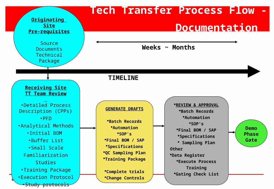
Tech Transfer Process Flow - Documentation
Receiving SiteTT Team Review
•Detailed Process
Description (CPPs)
•PFD
•Analytical Methods
•Initial BOM
•Buffer List
•Small Scale
Familiarization Studies
•Training Package
•Execution Protocol
•Study protocols
GENERATE DRAFTS
Batch RecordsAutomation
SOP’sFinal BOM / SAPSpecifications
QC Sampling PlanTraining Package
Complete trialsChange Controls
REVIEW & APPROVALBatch Records
AutomationSOP’s
Final BOM / SAPSpecifications Sampling Plan
OtherData Register
Execute Process
TrainingGating Check List
DemoPhase Gate
Originating Site
Pre-requisites
Source DocumentsTechnical Package
TIMELINE
Weeks ~ Months
51
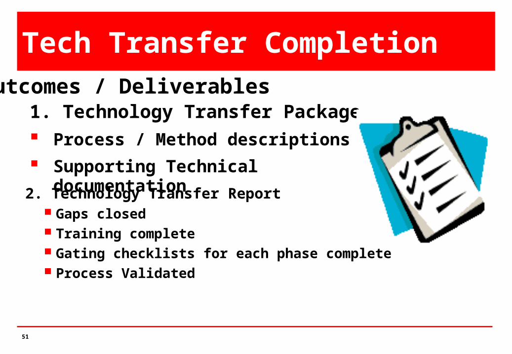
Tech Transfer Completion
2. Technology Transfer Report Gaps closed Training complete Gating checklists for each phase complete Process Validated
Outcomes / Deliverables1. Technology Transfer Package Process / Method descriptions
Supporting Technical documentation

52
Measure TT Success - Metrics
Measurement of data, value, timeframe, numbers Number of Deviations Operator or method errors Equipment failure Lots on hold Number of investigations Lots requiring rework Equipment malfunction

53
Measure TT Success - KPIs Key Performance Indicators (KPIs)
Normalizing a few metrics so that efficiencies or effectiveness can be compared
Number of lots required to complete validation Vs target Number of revalidations (target = 0) Number of lots failed in 100 lots Cycle time against target Yields against target Percent reworks (target = 0)