1. screen layout
TRANSCRIPT

1. Screen Layout You can see the below items according to your selection on function.
1.1. Icons in Live Display Mode
In Live display mode, icons will be indicated on the screen to notify the system mode or status.
Below are the icon categories, which are indicated on the monitor.
Icon to be shown
at right-upper corner on full screen mode
Icon to be shown
at left-bottom corner on each channel
Selects specific CH for full screen
When Motion Detected
Screen-Division mode
When Sensor Activated
SD card capacity usage status
PTZ
When USB memory stick & HDD
Recording
When DVR is accessed via network
Icon to be shown in 1ch full screen mode
Channel sequence mode
Digital x2 Zoom

1.2. Playback Buttons
If you select search mode, the status will be shown in the upper side of screen.
Now status
- This rectangular show the now status of playback.
- If you select ▶, the mark will be changed to ▶,
- And the mark will show ▶▶, when ▶▶ is selected
◀◀ Backward - Control backward speed.
- Move frame by frame reversely in pause mode
▶ Play/Pause - Play or Pause the video
▶▶ Fast Forward - Control forward speed.
- Move frame by frame forwardly in pause mode
■ Stop Stop the playback and go to Live mode
Quick Search
- If you select this Icon, the Search sub-menu will pop
up
Play speed -◀◀ / ▶▶ x8, x32, x128 supported
How to use Playback bar
MENU > SEARCH > select Search mode you want.
- Playback mode changing
To display different screen mode, select the Monitor Icon on screen and select different mode.
You can control playback speed with ◀◀ / ▶▶ button. Select ◀◀ / ▶▶ button once then it will
be x8, twice will be x32 then 3 times select is x128.
After selecting ■ (stop button) , message will pop up in case of selecting by mistake.
1.3. Other Icons
1.3.1 SD CARD STATUS
It shows the usage of SD card in percentage.
1.3.2. SCREEN SHOW STATUS
You can select how screen will display.
In Live MODE, there are 4 modes : Single, PIP, Sequence, Quad
In play mode, there are 2 modes : Single, Quad
Also, only quad mode can be operated in 4 channels.
- 2 -

1.3.3. CHANNEL ICON
You can change channel displays on screen. There are 1~4 in full screen.
1.3.4. USB ICON
This Icon will be shown after you attach USB into DVR,
1.3.5. NETWORK ICON
This Icon will be shown while someone access DVR through Network with CMS, or Web-viewer.
1.4. PIP mode (picture in picture)
In case of full screen display mode, you can see other camera with a small window.
(1) Select screen mode icon and select PIP mode.
(2) If you select PIP button again in PIP mode, the position of two screens will change each other.
1
2
‘PIP’ icon 2
1
(3) Select Ch no. in PIP mode to change small screen to desired screen.
2
Cam ‘1’ Button3
1
3
(4) Touch the screen or press direction keys to move small screen to desired position.
1
3
1.5. Sequence mode
- If you select SEQ button in case of FULL or QUAD screen mode, screen(s) will rotate
automatically.
- Default value of cannel changing interval is 2 or 3 seconds.
- User can select changing interval value from 1 to 99 seconds.
- User can select desired channel to display
- 3 -

1.6. Digital-ZOOM
If you select ZOOM key while in full screen mode, Digital-ZOOM function will work. If you select ZOOM key again, Zoom-Area window will be enlarged or diminished. If you press ENTER key, selected Zoom-Area will be displayed as full screen.
- 4 -
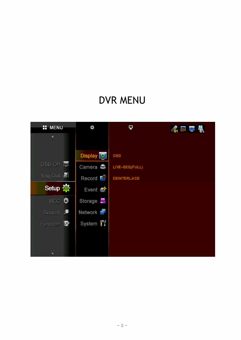
DVR MENU
- 5 -

2. HOW TO DISPLAY MENU WINDOW
Use touch screen or direction keys on the right side of KVR to select DVR menu or set up.
When using touch screen, press
desired menu. For direction keys,
you can move with it and select
certain menu with OK key.
2.1. SETUP
CAMERA DISPLAY RECORD EVENT STORAGE SYSTEM
MOTION
SENSOR
E-MAIL SCHEDULE
ALARM SCHEDULE
MISC
OSD
LIVE-SEQ(FULL)
DEINTERLACE
GENERAL
PRIVATE ZONE
PTZ
PRESET
SCAN POINT
COLOR
POSITION
PARAMETER
SCHEDULE
WATERMARK
MISC
SD FORMAT
AUTO-BACKUP
CONFIG
TIME
PASSWORD
KEY-TONE
UPGRADE
TURN OFF DVR
NETWORK
SET UP
STREAM
DDNS
CLIENT
ACCESS LIST
USER
- 6 -

3. SETUP MENU Going to setup menu, please select the <setup> icon
If the password Box will appear, please input “0000” in the box.
The password is set as “0000” in the factory.
If you input wrong password, the right window pops up.
[How to change password]
To change password, go to MENU > SYSTEM > PASSWORD
Then, input new password that you wish.
3.1 DISPLAY
When you select Display Icon, display menu is divided into
3 sub-menus;
OSD, LIVE-SEQ and DEINTERLACE
3.1.1. OSD
You can select which is displayed in the screen with choosing each icon.
● CAMERA NAME - Show camera name on screen.
● CAMERA NUMBER – Show each number of cameras on the screen.
● CAMERA BOARDER – Show outline of channel.
● LANGUAGE – Select OSD language.
● OSD HIDE – Hide all OSD, time, or Icon bar
● AUTO HIDE – Hide status bar automatically during not using DVR.
● LEFT MARGIN – Move the OSD position of leftmost
(E.g. Camera number, Camera Name, Network, USB, etc)
● RIGHT MARGIN – Move the OSD position of rightmost (E.g. Icons of HDD, POP, CH Status)
● TOP MARGIN – Move the OSD position to top (E.g. Icons of HDD, POP, CH status)
● BOTTOM MARGIN – Move the OSD position of bottom (E.g. Time-bar)
Margin value accept the numbers from 00 to 99.
- 7 -

bottom-
right-
top-
left-
● VGA/TV – Adjust OSD margin automatically according to CRT monitor or LCD monitor
After setting OSD, you should OSD OFF icon in MENU to hide OSD you selected.
3.1.2. DISPLAY-LIVE-SEQ(FULL)
- Set switching time to display a full screen in sequence.
- CH : Input desire channel no.
- TIME : Input desired switching time
- DEFAULT CH : Change to factory default value
- ALL TIME : same time is input to all channel.
NOTE : The time is second and maximum 99 second for
switching time can be entered.
3.1.3. DEINTERLACE
Please select “ON” if you don’t want to get
interlaced video with D1 resolution, then video
quality at D1 in playback will be better than setting
“OFF”.
3. 2. CAMERA When you select Camera Icon, Camera menu is
divided into 7 sub-menus;
GENERAL, PRIVATE ZONE, PTZ, PRESET, SCAN
POINT, COLOR, and POSITION
- 8 -

3.2.1. GENERAL
● NAME – Enter each camera name.
Maximum 15 digits in English can be input.
● COVERT – Show or Hidden the camera in Live mode.
ON: To covert, OFF: To show the camera
● AUDIO – Select connected audio channel.
● HOW to INPUT Character in TEXT INPUT box
(1) Move the Pointer into the Name Box and then select
(2) Move the pointer to desired letter with direction button.
(3) Press ENTER button or Select the desired letter.
(4) Then, selected letter will be shown at text window.
(5) Selecting desired letters, Select OK Icon.
3.2.2. PRIVATE ZONE
TO protect privacy, you can choose the zone which can not be recorded as well as seen on screen.
●How to set up the private zone
(1) Move and select the pointer the rectangular zone
which you want to select.
(2) Move and select the pointer another rectangular z
th
one,
e private zone will be set up as total rectangular.
2.2.3. PTZ
ID – Enter ID of PTZ camera.
l type of camera.
3.2.4. PRESET
CAMERA – Select specific camera to set up preset
o to next page.
ved presets.
●
● PROTOCOL – Select a protoco
● BAUD – Select a baud rate of camera.
●
position.
● PAGE – G
● CLEAR ALL – Cancel all sa
(1) Select camera.
- 9 -

(2) Select Icon. SET
(3) PTZ control screen of the camera will appear.
(4) Move pan, tilt, zoom in/out to desired point.
(5) Select Advance icon
Select any other position on screen or press MENU Key to cancel.
(6) if you like to cancel the setting, please select the CLE icon of the channel will be cleared. If
you select “clear all” icon, all value of channels will be cleared.
NOTE
- System records a certain position of PTZ device.
- Before using this function, please make sure that camera supports preset.
- Total 64 preset points can be saved to each channel.
3.2.5. SCAN POINT
● CAMERA – Select a specific camera to set up SCAN points.
● LIST – Create another SCAN list
● PRESET – Select desired preset position.
● CLEAR ALL – Cancel all saved scan points.
NOTE
- In SCAN point menu, you can set up PTZ tour route(SCAN-LIST) using saved PRESET position.
- You can create 4 scan lists for each camera. You should setup PTZ protocol and PRESET
Positions before setting Scan-List.
- You can create Max. 4 SCAN lists.
PTZ12 3sec PTZ04 ……..
PTZ04 3sec PTZ12 3sec PTZ04 3sec
Camera 1 will move to saved position as follows,
E.g. In this case,
3.2.6. COLOR
● CAMERA – Select camera to set up color.
● BRIGHT– Adjust bright of camera.
● CONTRAST – Adjust contrast of camera.
● COLOR/SATURATION – Adjust saturation of camera.
● COLOR/HUE – Adjust hue of camera.
● DEFAULT – Set all values to factory default.
- 10 -
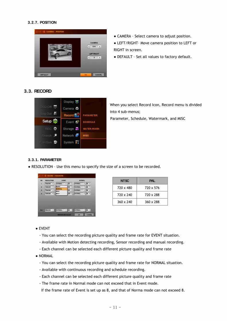
3.2.7. POSITION
● CAMERA – Select camera to adjust position.
● LEFT/RIGHT– Move camera position to LEFT or
RIGHT in screen.
● DEFAULT – Set all values to factory default.
3.3. RECORD
When you select Record Icon, Record menu is divided
into 4 sub-menus;
Parameter, Schedule, Watermark, and MISC
3.3.1. PARAMETER
● RESOLUTION – Use this menu to specify the size of a screen to be recorded.
NTSC PAL
720 x 480 720 x 576
720 x 240 720 x 288
360 x 240 360 x 288
● EVENT
- You can select the recording picture quality and frame rate for EVENT situation.
- Available with Motion detecting recording, Sensor recording and manual recording.
- Each channel can be selected each different picture quality and frame rate
● NORMAL
- You can select the recording picture quality and frame rate for NORMAL situation.
- Available with continuous recording and schedule recording.
- Each channel can be selected each different picture quality and frame rate
- The frame rate in Normal mode can not exceed that in Event mode.
If the frame rate of Event is set up as 8, and that of Norma mode can not exceed 8.
- 11 -

Record Quality Picture Quality Disk Space Need
BASIC Low Least
NORMAL Fair Medium
HIGH Good Big
BEST Excellent Most
● ALL
All channels would be changed according to selected resolution or quality or frame rate.
● REMAIN XXX / XXX / XXX
- Indicate the remaining frame number to record based on each resolution.
The remaining frame number
in case of selecting D1 resolution. The remaining frame number
in case of selecting CIF resolution.
The remaining frame number in case
of selecting Half D1 resolution.
3.3.2. SCHEDULE
System records according to schedule setting.
Specify the weekly schedule for each camera (hourly based)
► WATCH : No recording
► CONTINUOUS : Recording video continuously 24 hours a day.
► EVENTS : Recording video when event(Motion/Sensor/Video Loss) is triggered.
► CONT + EVENTS): Recording video when continuous or event is operated.
If there is no event, it will record video as continuous mode and
If there is event, it will record video as event mode as you set.
NOTE : The time in the first column of each line means 00 :00 ~00:59.
- 12 -
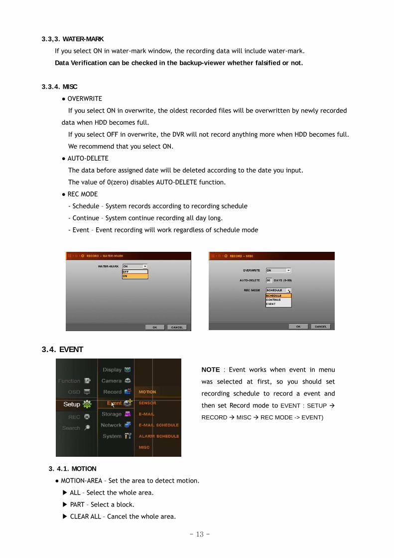
3.3,3. WATER-MARK
If you select ON in water-mark window, the recording data will include water-mark.
Data Verification can be checked in the backup-viewer whether falsified or not.
3.3.4. MISC
● OVERWRITE
If you select ON in overwrite, the oldest recorded files will be overwritten by newly recorded
data when HDD becomes full.
If you select OFF in overwrite, the DVR will not record anything more when HDD becomes full.
We recommend that you select ON.
● AUTO-DELETE
The data before assigned date will be deleted according to the date you input.
The value of 0(zero) disables AUTO-DELETE function.
● REC MODE
- Schedule – System records according to recording schedule
- Continue – System continue recording all day long.
- Event – Event recording will work regardless of schedule mode
3.4. EVENT
NOTE : Event works when event in menu
was selected at first, so you should set
recording schedule to record a event and
then set Record mode to EVENT : SETUP
RECORD MISC REC MODE -> EVENT)
3. 4.1. MOTION
● MOTION-AREA – Set the area to detect motion.
▶ ALL – Select the whole area.
▶ PART – Select a block.
▶ CLEAR ALL – Cancel the whole area.
- 13 -

● SENSITIVITY – Set the sensitivity of motion detection.
Sensitivity degree : 0 < 1 < 2 < ….. < 9
● ALARM-OUT – Set the alarm-out when motion is detected.
3.4.2. SENSOR
● RECORD – Select channel to record when a signal is detected from Sensor.
● TYPE – Select sensor type to match sensor type you have.
● ALARM-OUT – Set the alarm-out when a signal is detected.
3.4.3. E-MAIL
When below events happen, which will be notified to the registered email address by E-mail. You
can register three email address. Please remind that you can select event type after selecting
Event email is ON.
MOTION
POWER ON
SENSOR
HDD ERROR
VLOSS
Event E-mail : Select ALL TIME or SCHEDULE to use Email notification.
Event type : Select Event type to notify by email
SENDER ID : Input DVR name or letters
E-mail address : Input your email address to receive event information from DVR.
For example : [email protected]
- 14 -

Ex) Email message
From : [email protected]
To : [email protected]
Sent: Friday, July 24, 2009 6:11 PM
Subject: EVENT MESSAGE [2009/07/24 18:10:11] [testdvr/192.168.001.121] MOTION ch 1 ON
3.4.5. E-MAIL SCHEDULE
This function works when you select SCHEDUEL as the value of EVENT E-MAIL in E-mail MENU.
You can get email from DVR according to schedule you select date or time.
3.4.6. ALARM SCHEDULE
If you select the date or time you want , the Buzzer goes off, after the value of alarm-out was chosen
as any value in each sub menu of EVENT, when the related things happen during the selected times.-
3.4.7. MISC
● PRE-REC TIME – Enter recording time (0~30sec) before the time when event occurs
● POST-REC TIME – Enter recording time (0~120sec) after the time event occurs.
● BUZZER – Buzzer will be sounded when alarm is out , if ON is selected.
● DWELL TIME – Enter the duration time of alarm out when event occurs.
● EVENT POPUP – When event happens, the channel will pop up if ON is selected.
● POPUP SEQUENCE TIME – Switching time to display popup channels
Newer event will pop up.
Note> If event occurs during dwell time of another event, dwell time will be ignored and
- 15 -

3.5. STORAGE 3.5.1. SD FORMAT
If you want to format SD card, please select FORMAT button
3.5.2. AUTO-BACKUP (MIRROR)
You can connect USB type external HDD into DVR to use mirroring function.
- Mirroring : The same data being recorded in SD card will be recorded in external HDD.
If you want to format external HDD in this menu, HDD is formatted as file system FAT32 and
backup viewer is copied in external HDD.
<USB HDD : Note that USB-HDD must be external power source>
3.6. NETWORK
3.6.1. SETUP
(1) STATIC,
Basically, you can choose one among STATIC, DHCP, and ADSL(PPPOE). If you choose DHCP mode,
DVR system gets IP address automatically from IP router if connected, and If you choose STATIC
mode, input IP address which is connected to DVR.
(2) ADSL(PPPOE)
- 16 -

If you use ADSL model, select ADSL and enter PPPOE ID and PASSWORD. If you don’t know ID and
Password, please contact your ADSL service provider.
3.6.2. STREAM
You can set up the recording rate and Network transfer rate separately.
If you select “ON” in dual streaming, you can set up the network transfer rate differently with the
recording rate. Note that network transmission rate will be max. 120fps at CIF resolution if it is 'ON'.
If you select “OFF” in dual streaming, the network transfer rate follows the recording rate.
kinds of parameter can be chosen
Resolution Normal Frame
360*240
720*240
720*480
Basic
Normal
High
Best
1, 2,
4, 8,
15, 30
3.6.3. DDNS
DVR supports DDNSCCTV.COM, DYNDNS.COM and NO-IP.COM for DDNS connection. For details of
instruction, please refer to DDNS manual in the CD supplied.
NOTE : Before setting DDNS, you should be registered on the website www.ddns.com,
www.dyndns.com or www.no-ip.com at first
● SERVER - Choose server type.
● USER ID - Enter your site ID be registered on website
● PASSWORD - Enter your site PASSWORD be registered on website
● HOST NAME - Enter your host name be registered on website.
After setup of DDNS, select TEST Icon to verify the connection to DDNS site.
- 17 -

3.6.4. CLIENT
Choose one of given CLIENT PORT list, and enter desired value at WEB PORT, whose default value is
0080. Remember those values you have entered for the following setup. For WAN connection, you have
to set port forwarding in router with the selected web, client port on DVR. For more details, please
refer to the manual of your router.
UPNP (Universal plug & play)
If you activate UPNP function, you don’t need to do port forwarding. (In order to use this
function, router that DVR is connected to should support UPNP function as well)
After checking UPNP, select client port and input web port as you wish. If you select port
that is being used for other network device, dialog message will pop up “PORT IN USE”
In that case, select another client port and input another web port that is not used.
3.6.5. ACCESS LIST
Registered IP address is allowed to access DVR. If you set at least one IP address, then only entered
Client IP address(es) would be allowed to access DVR. However, if you do not register any client IP
address, any clients can access DVR.
3.6.6. USER
Register up to 4 users that can access to DVR remotely via network (CMS, Web and mobile phone
application) –Default ID : USER1, USER2, USER3, USER4 –Password : 0000
- 18 -

3.7. SYSTEM
When you select SYSTEM Icon, SYSTEM menu is
divided into 6 sub-menus;
CONFIG, TIME, INPUT DEVICE, USER, UPGRADE and
TURN OFF DVR.
3.7.1. CONFIG
You can save(import) system setting values to USB device or can load(export) system setting values
from USB device in order to make other DVR(s) as same setting values .
● CONFIG IMPORT– Load the saved configuration file from USB device and input to product.
● CONFIG EXPORT– Save present system configuration values to USB device.
● DEFAULT – Change setting value to factory default.
3.7.2. TIME
● DATE FORMAT – Select Date format.
● TIME FORMAT – Select type of time indication
● TIME ZONE – Select your area to make adjustment of time zone.
- 19 -

Please remind that the system will reboot, when you change the time zone.
● TIME SYNC
This function is for synchronizing the time of DVR periodically
with that of the connected server by every hour.
● SERVER IP – Enter IP address of time server.
Select TEST and press ENTER button to check if time sever is working.
If this function is selected, DVR refer the time of Time zone every one hour,
And then time of DVR will be changed to match that of time server.
E.g. time.kriss.re.kr (www.time.kriss.re.kr X)
● CHANGE TIME – Time will be changed by manual if the time server is not selected.
3.7.3. PASSWORD
There are 2 users who can control DVR (ADMIN, USER). In this menu, you can modify password for the
users. You can also check ON/OFF for SETUP, LOGIN, RECORD, SEARCH, BACKUP and checked functions
would require password when you want to get into them.
3.7.4. KEY-TONE
Select ON/OFF for key-tone sound.
3.7.5. UPGRADE
If you open this menu, you can see the current firmware version of DVR.
If you would like to upgrade firmware of DVR, please follow the below steps.
If you select upgrade icon, the small upgrade window will pop up
There are two ways; USB UPGRADE, NETWORK UPGRADE.
NOTE : There is two methods to upgrade the DVR system. - USB UPDATE - Upgrade the DVR system by using USB memory stick.
- NETWORK UPDATE - Upgrade the DVR system through Internet.
- 20 -

3.7.5.1 USB UPGRADE
Please select USB upgrade in upgrade window
(1) Copy provided firmware file to your USB memory stick
(2) Attach USB Memory which includes Firmware into USB Port.
(3) Enter UPGRADE icon to upgrade firmware, then small windows will appear.
(4) Please select OK Icon and the message dialogue to confirm will popup,
(5) And please select OK, or CANCEL to proceed.
(6) It will take some minutes to upgrade, and then DVR will be rebooted automatically after
upgrade is finished.
3.7.5.2. Network upgrade
Please select network upgrade in upgrade window
(1) Select UPGRADE , then small window will appear.
(2) Select NETWORK UPGRADE and press ENTER button.
(3) Check out whether Server IP and FILE NAME are correct. If shown information is wrong,
correct SERVER IP and FILE NAME and press ENTER button to input new information by text
input Dialog box.
NOTE : Make sure the information of Server IP & File name through your supplier.
(4) Select OK and press ENTER button to start S/W upgrade.
After completing upgrade, the system will reboot automatically.
3.7.6. TURN OFF DVR
If you want to turn off DVR, please press ‘TURN OFF DVR’ then press ‘OK’ button
as below screen.
- 21 -

4. SEARCH
This Menu is divided into 5 sub-menu;
By time, By Calendar, By Event, Go to first and Go to last.
Please Select or press SEARCH button, The Sub-menu of
SEARCH will pop-up. And then if you select the value in one of
them, the playback bar Will be shown, and please see the
page 13 to get how to control.
4.1. SEARCH BY TIME
(1) Enter desired date and time to search for.
(2) Then, move the pointer to OK and press ENTER button.
It is the start point to play back the data.
4.2. SEARCH BY CALENDAR
(1) If you select SEARCH BY CALENDAR, the calendar will appear as the below.
(2) Select desired date by pressing ◀▶▲▼ buttons and press ENTER button.
(3) Select desired Hour/Min by pressing ◀▶▲▼buttons and press ENTER button.
(4) Select OK and press ENTER button.
NOTE
The color of Date is gray if there is no any recording. But the color of date turns Black when
the recording data of that date exists.
When you select the date which turned Black, the time bar will be shown including white,
and red rectangular on Hour and Minutes.
White bar does not include recording data, and the data exist in red color.
If you select one red rectangular of Hour bar, its color changed to brown, and the color of
minute bar will be changed to red if there is recording data in those minutes.
And then, if you select one of these rectangular, the starting point is selected to play the
recording data. The data will be played back when you select OK icon.
- 22 -

4.3. SEARCH BY EVENT
(1) If you select SEARCH BY EVENT, the following window will appear.
(2) Enter desired start time and end time to find EVENT.
(3) Select desired channel to search for.
(4) Select desired event type to search for.
(5) Select SEARCH button and press ENTER button.
4.4. GO TO FIRST : Play starts from oldest recorded data.
4.5. GO TO LAST : Play starts from latest recorded data.
5. FUNCTION
FUNCTION menu is divided into 4 sub-menu; PTZ, AUDIO,
BACKUP, and LOG VIEW
5.1. PTZ
Select PTZ in Function Menu, screen will be changed to FULL screen mode and you can
control PTZ camera.
If you select advance Icon in PTZ window, PTZ- ADVANCE window will pop-up.
5.1.1. PTZ BASIC
If you press ◀▶▲▼ button, camera will pan to left / right or
tilt up / down.
If you press ◀◀ / ▶▶ button or Select (+), (-) Icon, the camera
will zoom in or out.
- 23 -

5.1.2. PTZ ADVANCE
FOCUS
① + : Focus-IN.
② - : Focus-OUT
③ AUTO : AUTO-FOCUS mode.
IRIS
① + : Open Iris.
② - : Close Iris.
③ AUTO : AUTO-IRIS mode.
SPEED
① + : The control speed will increase.
② - : The control speed will decrease.
PRESET
① If you want to go to a specific PRESET-position, select “GO” button.
② If you want to scan PRESET-positions, select “SCAN” button
NOTE
- The PRESET-positions are set by PRESET menu [MENU SETUP CAMERA PRESET]
- The SCAN-lists are set by SCAN-POINT menu [MENU SETUP CAMERA SCAN-POINT]
OSD MENU
If you select OSD MENU icon in case that Camera itself has OSD function, The OSD will be
shown in accordance with Camera’s OSD.
If OSD is not supported by Camera, OSD MENU does not work.
NOTE
- OSD Control function supports only for “Pelco-D” protocol
5.2. Audio
Set audio output to make sounds at external speaker.
Audio works only at full screen mode.
You can control audio volume
Before setting Audio volume, you can test it by using ON/OFF test Icon
- 24 -

5.3. Backup
You can back up the data you want to store or keep to USB Device.
For USB backup, connect USB device to USB port of DVR system.
Select Channel and time you want, and then move and Select the pointer to BACKUP Icon.
● DEVICE – Select device to backup
● CHANNEL – Select desired channel
● TO AVI – Can make backup file as AVI file
● SMI – Time stamp to indicate time / data at AVI file.
- Backup viewer is automatically copied
to the device together with backup data
● FROM – Enter starting date time to backup
● TO – Enter ending date time to backup
NOTE
- One channel only can be selected and can backup by USB memory
- Backup viewer is automatically copied to the device together with backup data
5.4. Log view
You can see the system log status or
save it into USB memory and see it in PC.
● EVENT TYPE – Select desired event type
● FROM – Enter starting date & time
● TO – Enter ending date & time
● BACKUP – Save log data into USB memory
● SEARCH – If you select SEARCH Icon, you can see log list in DVR.
6. OSD OFF If you select OSD OFF in MAIN MENU, something displayed on screen will disappear according to your
selection on OSD MENU
You can get more information on this below.
[ SETUP->DISPLAY->OSD->OSD HIDE-> EACH PARAMETERS ]
7. REC If you select REC in main Menu, recording will start or be stopped by toggle. The some steps should
be advanced before record is selected.
Please Check whether the value of date and time is properly set.
- Check if HDD is formatted. If HDD is not formatted, please format HDD.
[If the HDD is not formatted yet, please see Page .[How to format HDD]
- Please come back to Record sub-menu of SETUP.
- Choose suitable values in parameter and schedule.
- The recording depends on your selection on schedule.
- 25 -

*Specification
Specification 4 Channel DVR
Video(BNC) 4
Audio(RCA) 1 INPUT
Sensor 1
Composite(BNC) 1
VGA 1
AUDIO(RCA) 1 OUTPUT
Alarm(Relay) 1(1)
PORT USB 1 x USB ports, 1 x PTZ(RS-485), 1 x Ethernet Port
Digital Zoom X2 Live
Monitoring Mode 1,4 & PIP
Resolution NTSC - 720*480, PAL - 720 * 576
Frames at [CIF] 120 / 100
Frames at [H. D1] 120 / 100
Frames at [D1] 60 / 50
Pre/Post Rerecording Pre (0 ~ 30 Seconds), Post (0~120 seconds)
Recording
Recording Mode Manual/ Continuous/Schedule/Motion/Sensor
Speed Fast Forward/Backward(x1/8/32/128), Frame by frame Playback
Search Method By time, Calendar, Events and Go to First/Last Data
Local Recording & Network Transmission Dual Stream
Network Transmission rates max.120/100FPS at CIF
Web (I.E) Live/Playback/Audio/PTZ/Snapshot
CMS Live/Playback/Backup/PTZ/Remote Setup/Local DVR Rebooting
DDNS Support free DDNS server-ddnscctv.com/dyndns.com/no-ip.com
Mobile Viewer 3G Mobile Phones, iPhone, Android phone
Network
Bandwidth Adjustable (64/128/256/512Kbps,1/2/4/10Mbps, Unlimited)
Events & Video Loss Email Notification, Alarm-Out, Buzzer for Events & Video Loss
Motion Detection Selected Area, sensitivity in each channel
Events
&
Alarm Scheduling mail Notification Schedule/Alarm Schedule for Events-Trigger
Storage Internal
OS Linux
Control
Backup Device USB Memory Stick / HDD, Network by CMS
User management 2 local users & 4 network users
Firmware Upgrade USB flash memory, Network, CMS
System
Log View System operation status
- 26 -

- 27 -