1 round robin geometric dimensional and tolerance assessment of additive manufacturing technologies...
TRANSCRIPT

1
Round Robin Geometric Dimensional and Tolerance
Assessment of Additive Manufacturing Technologies
Round Robin Geometric Dimensional and Tolerance
Assessment of Additive Manufacturing Technologies
Vincent Capobianco MS 218-5-2015

2
Contents
• Outline (3)• Participant Instructions (4)
Purpose & Objectives (5) Artifact Definitions (6-9) Build Plate & Artifact Designation (10-15) Artifact Size Designation (16-18) Part Fill (19) Tier Selection & Artifact Orientation (20-26) Post Processing (27-29)
• Summary & Conclusions (30-32)• Contact & Shipping (33-34)
3
Outline• This proposal requests the printing of the
enclosed parts by DoD and industry to aid in the development of an AM evaluation process.
• Printed parts will be evaluated by NSWC Corona to determine the geometric dimensional and tolerance variations that can occur within an additive manufacturing envelope.
• Results of the analysis shall be open and be provided to all participants to view the GD&T performance of each machine at each participant’s location.
• Participation in the round robin test is voluntary. Printing costs are covered by the participant, while analysis cost is covered by NSWC Corona.
4
Participant Instructions
1. Determine Level of Participation Artifact Size (Choose 50%, 100% or 150% scale) Part Fill (Choose Sparse or Solid Fill) Tier Structure (Choose Level I, II, or III)
2. Print Parts According to Prescribed Procedure
3. Follow Recommended Support Material Removal
4. Mark Parts Accordingly 5. Fill Out Survey (Attached Document)
Provide Artifact Size, Part Fill, Tier Structure Machine information
6. Return Parts & Survey to NSWC Corona as Directed

5
Purpose and Objectives
• Purpose TodevelopanevaluationprocessoftheGeometricDimensionalandToleranceVariationswithinthemanufacturingenvelopeofAMTechnology.
• Objectives DevelopcollaborationwithindustryandDoDintheparticipationofthisstudy
Collecttheadditivemanufacturedpartsacrossdifferingtechnologiesandcollecttestspecimens
MeasurespecimensandcompareGD&Tvariationsbetweenspecimens
ProvideparticipantswithresultsanddevelopamorematureevaluationprocessofAMtechnology
6
Artifact Definitions
7
Round Robin Artifacts
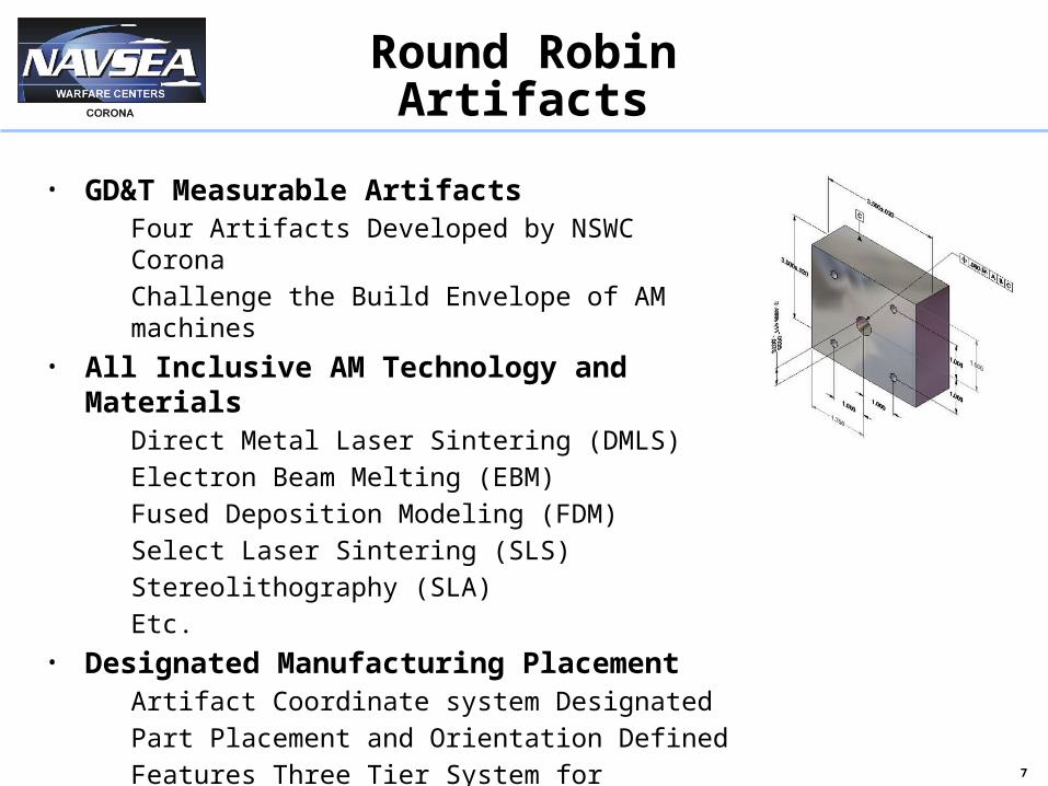
• GD&T Measurable Artifacts FourArtifactsDevelopedbyNSWCCorona ChallengetheBuildEnvelopeofAMmachines
• All Inclusive AM Technology and Materials DirectMetalLaserSintering(DMLS) ElectronBeamMelting(EBM) FusedDepositionModeling(FDM) SelectLaserSintering(SLS) Stereolithography(SLA) Etc.
• Designated Manufacturing Placement ArtifactCoordinatesystemDesignated PartPlacementandOrientationDefined FeaturesThreeTierSystemforSelectionofParts
MultipleSizeofPartsAvailable
8
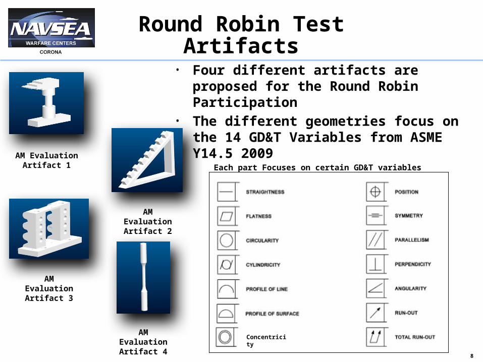
Round Robin Test Artifacts
• Four different artifacts are proposed for the Round Robin Participation
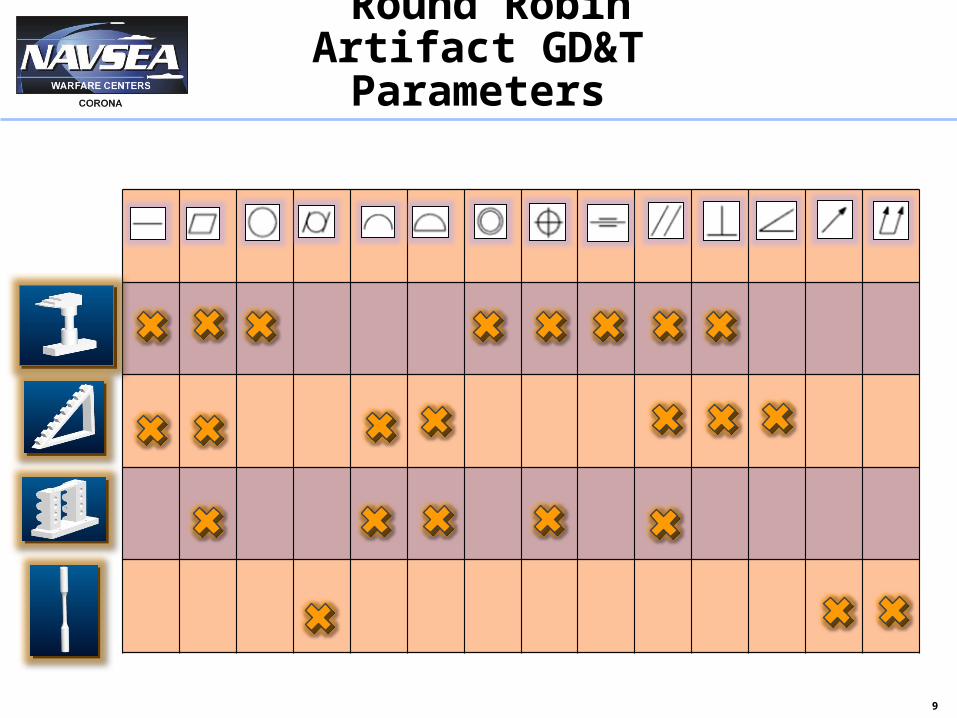
• The different geometries focus on the 14 GD&T Variables from ASME Y14.5 2009 Each part Focuses on certain GD&T variables GD&T features measured using CMM
AM Evaluation Artifact 1
AM Evaluation Artifact 4
AM Evaluation Artifact 3
AM Evaluation Artifact 2
Concentricity
9
Round Robin Artifact GD&T Parameters
10
Build Plate & Artifact Designation
11
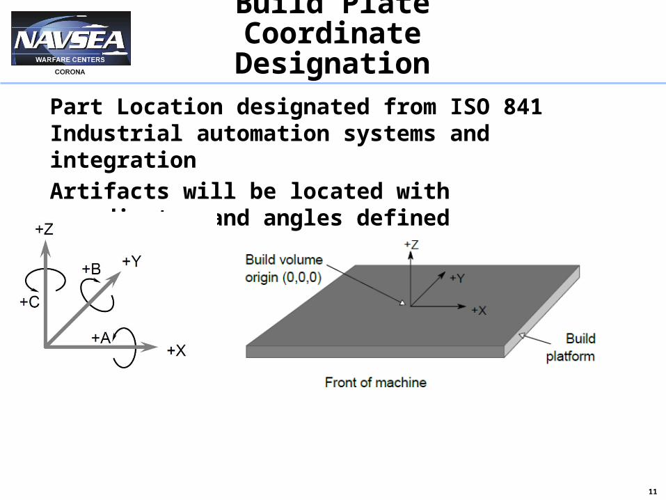
Build Plate Coordinate Designation
Part Location designated from ISO 841 Industrial automation systems and integration
Artifacts will be located with coordinates and angles defined
12
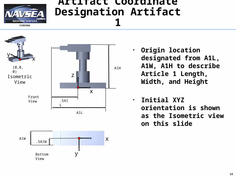
Artifact Coordinate Designation Artifact
1
xy
z
(0,0,0)
x
z
FrontView
BottomView
x
y
• Origin location designated from A1L, A1W, A1H to describe Article 1 Length, Width, and Height
• Initial XYZ orientation is shown as the Isometric view on this slide
A1W
.5A1L
A1L
A1H
.5A1W
IsometricView
13
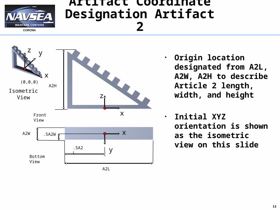
Artifact Coordinate Designation Artifact
2
• Origin location designated from A2L, A2W, A2H to describe Article 2 length, width, and height
• Initial XYZ orientation is shown as the isometric view on this slide
x
yz
(0,0,0)
x
z
A2L
y
A2H
A2W
.5A2L
.5A2W
x
BottomView
FrontView
IsometricView

14
Artifact Coordinate Designation Artifact
3
• Origin location designated from A3L, A3W, A3H to describe Article 3 length, width, and height
• Initial XYZ orientation is shown as the isometric view on this slide
x
yz
(0,0,0)
A3L
.5A3L
BottomView
A3W .5A3W
FrontView
A3H
x
y
z
x
IsometricView
15
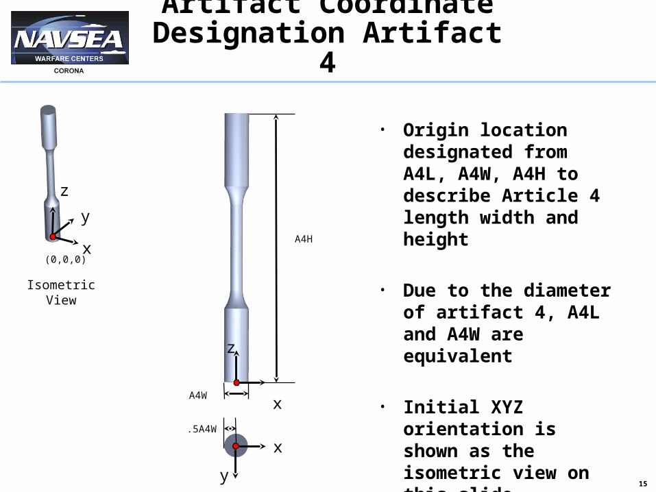
Artifact Coordinate Designation Artifact
4
• Origin location designated from A4L, A4W, A4H to describe Article 4 length width and height
• Due to the diameter of artifact 4, A4L and A4W are equivalent
• Initial XYZ orientation is shown as the isometric view on this slide
x
y
z
(0,0,0)
x
y
A4H
A4Wx
z
.5A4W
IsometricView

16
Artifact Size Designation
17
Artifact Size Definition
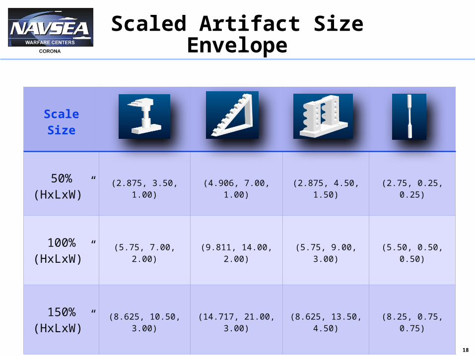
• Multiple Sizes Available for Selection 150% Scale 100% Scale 50% Scale Participant chooses the largest parts
they can produce between 150%, 100%, and 50% scale
• Drawings of Full Scale Parts are Provided Showing GD&T
18
Scaled Artifact Size Envelope
ScaleSize
50%(HxLxW)”
(2.875,3.50,1.00) (4.906,7.00,1.00) (2.875,4.50,1.50)
(2.75,0.25,0.25)
100%(HxLxW)”
(5.75,7.00,2.00) (9.811,14.00,2.00)
(5.75,9.00,3.00) (5.50,0.50,0.50)
150%(HxLxW)”
(8.625,10.50,3.00)
(14.717,21.00,3.00)
(8.625,13.50,4.50)
(8.25,0.75,0.75)
19
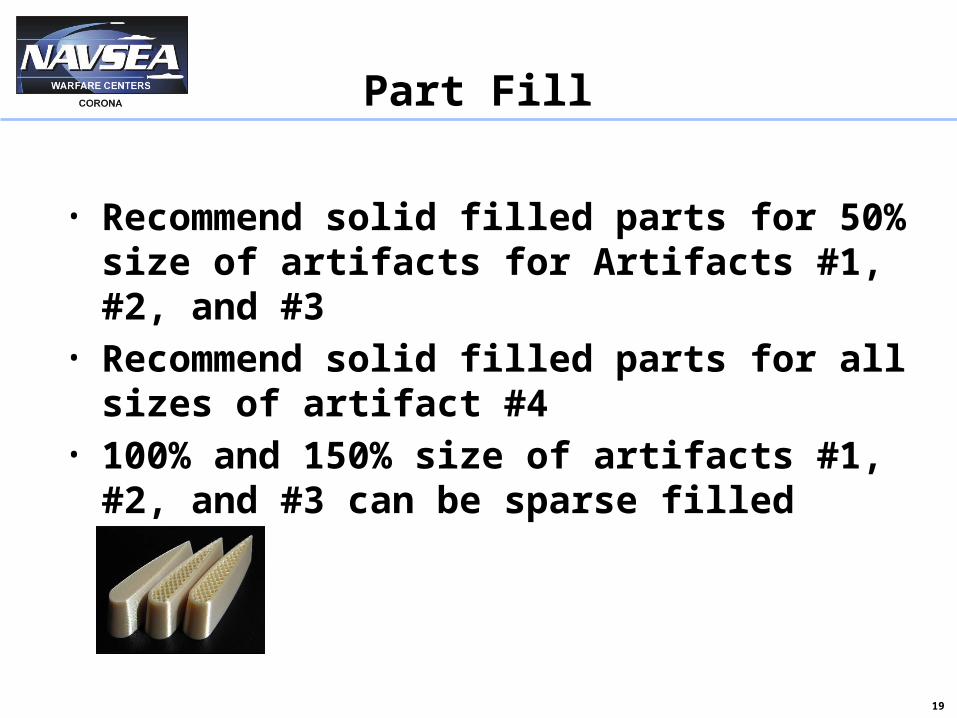
Part Fill
• Recommend solid filled parts for 50% size of artifacts for Artifacts #1, #2, and #3
• Recommend solid filled parts for all sizes of artifact #4
• 100% and 150% size of artifacts #1, #2, and #3 can be sparse filled
20
Tier Selection & Artifact Orientation
21
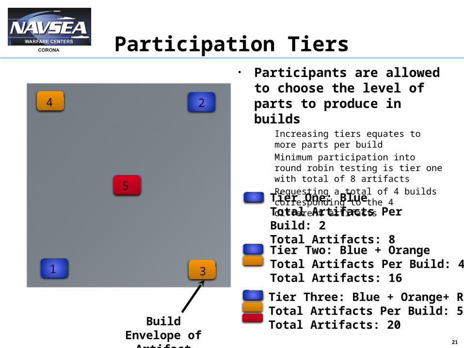
Participation Tiers
1
Build Envelope of
Artifact
5
4
3
2
• Participants are allowed to choose the level of parts to produce in builds Increasingtiersequatestomore
partsperbuild Minimumparticipationintoround
robintestingistieronewithtotalof8artifacts
Requestingatotalof4buildscorrespondingtothe4differentartifacts
Tier One: BlueTotal Artifacts Per Build: 2Total Artifacts: 8Tier Two: Blue + OrangeTotal Artifacts Per Build: 4Total Artifacts: 16
Tier Three: Blue + Orange+ RedTotal Artifacts Per Build: 5Total Artifacts: 20
22
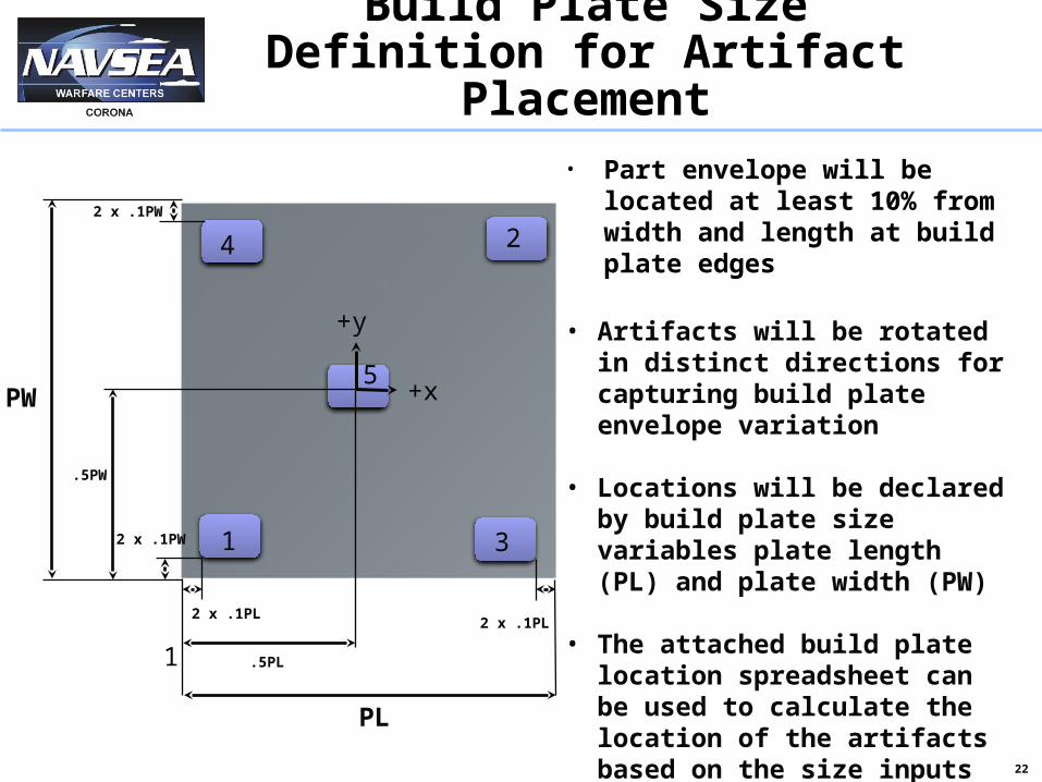
Build Plate Size Definition for Artifact Placement
+x
+y
PW
PL
2 x .1PW
2 x .1PL
2 x .1PW
2 x .1PL
.5PL
.5PW
• Part envelope will be located at least 10% from width and length at build plate edges
• Artifacts will be rotated in distinct directions for capturing build plate envelope variation
• Locations will be declared by build plate size variables plate length (PL) and plate width (PW)
• The attached build plate location spreadsheet can be used to calculate the location of the artifacts based on the size inputs of the build plate
2
1 3
1
5
4
23
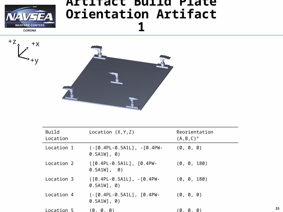
Artifact Build Plate Orientation Artifact 1
Build Location Location (X,Y,Z) Reorientation (A,B,C)°
Location 1 (-[0.4PL-0.5A1L], -[0.4PW-0.5A1W], 0) (0, 0, 0)
Location 2 ([0.4PL-0.5A1L], [0.4PW-0.5A1W], 0) (0, 0, 180)
Location 3 ([0.4PL-0.5A1L], -[0.4PW-0.5A1W], 0) (0, 0, 180)
Location 4 (-[0.4PL-0.5A1L], [0.4PW-0.5A1W], 0) (0, 0, 0)
Location 5 (0, 0, 0) (0, 0, 0)
+x
+y
+z
24
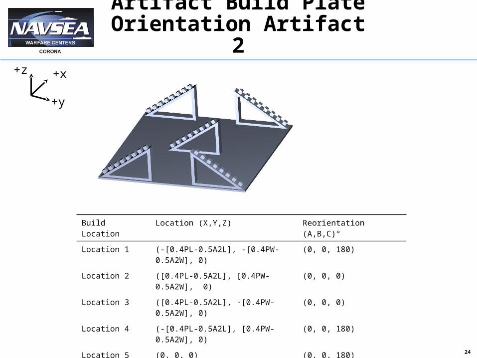
Artifact Build Plate Orientation Artifact 2
Build Location Location (X,Y,Z) Reorientation (A,B,C)°
Location 1 (-[0.4PL-0.5A2L], -[0.4PW-0.5A2W], 0) (0, 0, 180)
Location 2 ([0.4PL-0.5A2L], [0.4PW-0.5A2W], 0) (0, 0, 0)
Location 3 ([0.4PL-0.5A2L], -[0.4PW-0.5A2W], 0) (0, 0, 0)
Location 4 (-[0.4PL-0.5A2L], [0.4PW-0.5A2W], 0) (0, 0, 180)
Location 5 (0, 0, 0) (0, 0, 180)
+x
+y
+z
25
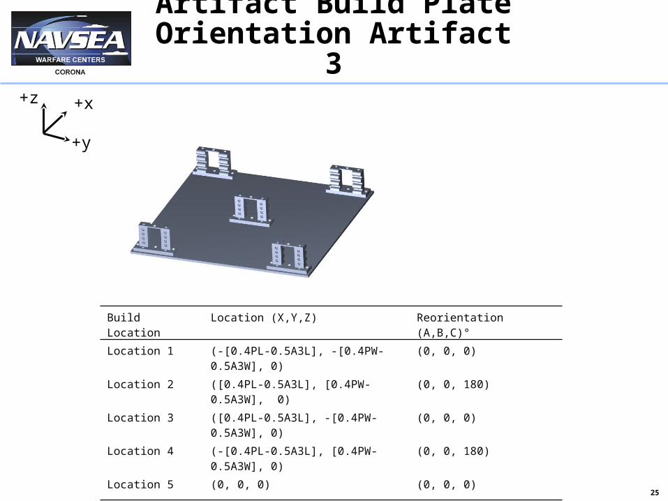
Artifact Build Plate Orientation Artifact 3
+x
+y
+z
Build Location Location (X,Y,Z) Reorientation (A,B,C)°
Location 1 (-[0.4PL-0.5A3L], -[0.4PW-0.5A3W], 0) (0, 0, 0)
Location 2 ([0.4PL-0.5A3L], [0.4PW-0.5A3W], 0) (0, 0, 180)
Location 3 ([0.4PL-0.5A3L], -[0.4PW-0.5A3W], 0) (0, 0, 0)
Location 4 (-[0.4PL-0.5A3L], [0.4PW-0.5A3W], 0) (0, 0, 180)
Location 5 (0, 0, 0) (0, 0, 0)
26
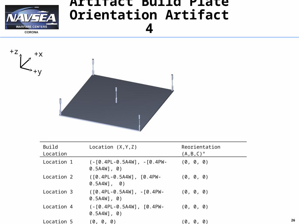
Artifact Build Plate Orientation Artifact 4
+x
+y
+z
Build Location Location (X,Y,Z) Reorientation (A,B,C)°
Location 1 (-[0.4PL-0.5A4W], -[0.4PW-0.5A4W], 0) (0, 0, 0)
Location 2 ([0.4PL-0.5A4W], [0.4PW-0.5A4W], 0) (0, 0, 0)
Location 3 ([0.4PL-0.5A4W], -[0.4PW-0.5A4W], 0) (0, 0, 0)
Location 4 (-[0.4PL-0.5A4W], [0.4PW-0.5A4W], 0) (0, 0, 0)
Location 5 (0, 0, 0) (0, 0, 0)

27
Post Processing
28
Support Material Removal
• Request support material removed from artifacts Metallics
• Minimal machining to remove support material only
Dissolvable Materials• Remove support material through
dissolvable support material removal process
• Please ship parts to the address provided on slide 34
• Please complete survey and return to Vincent Capobianco

29
Part Identification
• For itemization, request that the parts are marked with a sharpie after removing them from the build plate
• Please mark the numerical location, (1-5) on the bottom of the parts

30
Summary & Conclusions
31
Summary
• Timeline Requesting parts and survey no later
than 30 days after release of round robin testing Project call
Report provided in fourth quarter 2015 of GD&T comparisons
Results of the analysis shall be open and be provided to all participants to view the GD&T performance of each machine at each participant’s location
32
Conclusion
• Collection of measurement data and report post analysis will be provided comparing GD&T and variations of individual artifacts across all AM technologies
• Outline of Inputs that effect GD&T User Experience Material and Process Recorded Temperature Recorded Pressure Part Size Location Part Fill
33
Contact
• For more information please contactProject Lead Vincent Capobianco (MS 21)
• [email protected] 951-393-4048
Branch Manager Henry Meinders (MS 21)
• [email protected] 951 393-4190

34
Shipping Address
• Please Ship Round Robin Artifacts to
Naval Surface Warfare Center CoronaAttention: Vincent Capobianco (MS 21)1999 Fourth StNorco, CA 92860