1 roadside equipment architectures for dsrc-enabled applications using traffic signal phase and...
TRANSCRIPT
1
Roadside Equipment Architectures for DSRC-enabled Applications Using
Traffic Signal Phase and Timing Information
Susan R. DickeySomak Datta GuptaJames A. Misener
David Nelson
ITSA Annual MeetingTS10
May 4, 2010

2
Agenda
• PATH Experience• Partitioning SPAT
Uses– Local– Global– Use Cases
• Alternate Configurations• Last Words: Generalized Approach

3
California PATHSPAT Experience
PATH experience in sending SPAT since 2003…• Close relationship with Caltrans, both the Division of Research and Innovation and the local
District 4, gives practical perspectice• Richmond Field Station Smart Intersectio
– different traffic signal controller types– variety of communications technologies, wired and wireless
• California Vehicle Infrastructure Integration (VII) Testbed,• DSRC SPAT demonstrations
– Turner Fairbank Highway Research Center in 2003– ITS World Congresses in 2005 and 2008
3

4
California PATH Smart Intersection (2004-present)
• Initially WiFi was used to deliver in-vehicle warnings and enable SV/POV/RSE communication for driver behavior research.
• Kapsch-TraffiCom IEEE 1609 capable MCNU has been installed
• Savari MobiWAVE and ITRI radios have also been installed.
5
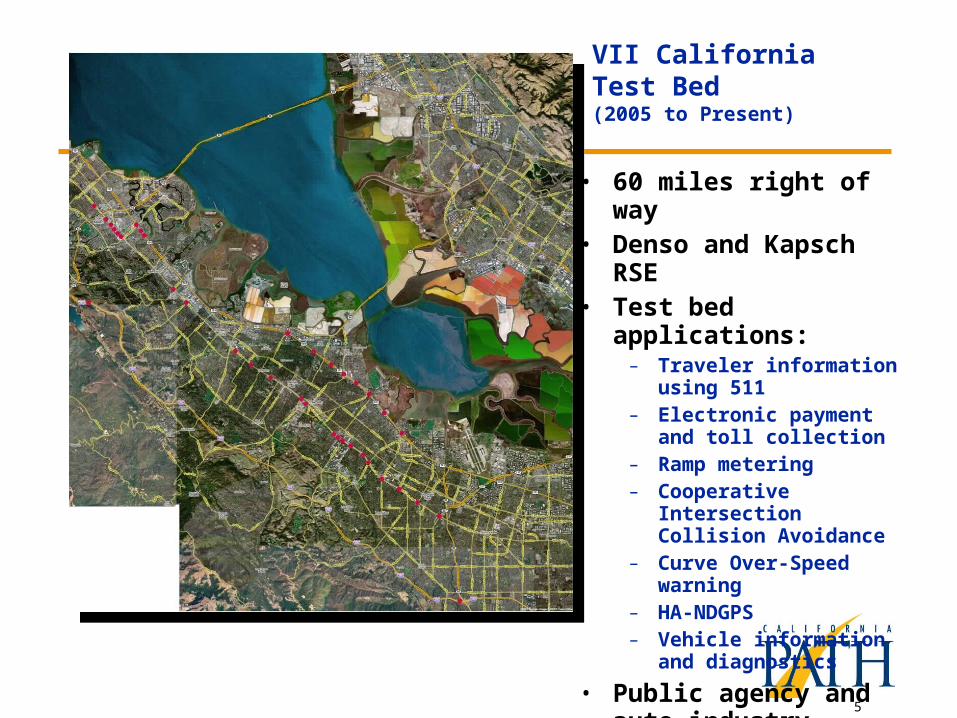
VII California Test Bed (2005 to Present)
• 60 miles right of way• Denso and Kapsch RSE• Test bed applications:
– Traveler information using 511
– Electronic payment and toll collection
– Ramp metering– Cooperative Intersection
Collision Avoidance– Curve Over-Speed
warning– HA-NDGPS– Vehicle information and
diagnostics
• Public agency and auto industry partners.

6
PATH Signal Phase Software: History
• 170 – AB3418 (TSP Project, 2002)– Sniffer (Page Mill, 2006)
• 2070– NTCIP serial (Turner
Fairbank, 2003; RFS, 2004)– AB3418 (ECR/Fifth, 2007)
• Econolite ASC/3-2100– NTCIP ethernet (World
Congress, 2005)
www.viicalifornia.org

7
Signal Phase Count-Down and Broadcast Software: Modular Design
Data Server
Phase Countdown
Sniffer
AB3418
NTCIP
Message Broadcast
Any signal information source may be used, with no change to other modules
Broadcast devices and formats can be changed, with no impact to other modules
www.viicalifornia.org

8
PATH ATCP 2070 Controller
• A “Traffic Control PC”, utilizing ATC 2070 hardware• Open architecture and open source software• Layer (modular) construction
– Field I/O layer provides a interface for traditional input (loop, pedestrian push button) and output (traffic signal bulbs and pedestrian signs)
– Communications layer provides interface for advanced input (IntelliDrive, TSA request) and output (SPAT)
– Control layer (open source) • Better adaptability to advances in technology• Ensures interoperability within systems• A platform and environment
– Test new technology– Conduct repeatable experiments
9
Current Use
• Controls traffic lights at Richmond Field Station test intersection
• Used by FHWA TFHRC SBIR Contractor• Supports
– Fixed-time control– TSP (green truncation and extension)– CICAS-TSA all-red extension– CICAS-SLTA driver behavior experimental
study– Real-time performance monitoring

10
New Work with SPAT
• FHWA Exploratory Advanced Research Proposal (Advanced Traffic Signal Control Algorithms): Caltrans, PATH, BMW– Base idea: Use vehicles as probes– Can use DSRC or other (3G, 4G) wireless
communications between intersections– Use and fuse field elements (discrete detectors)
where available– Uses modern control theory
• State Pooled Fund Study: Investigating the Potential Benefits of Broadcasted SPAT Data under IntelliDrive

11
Emergent Use Case Table
SafetyCICAS – including the full range of CICAS-V, CICAS-
SLTA and TSA
Display of real-time signal status information to driver (based on Japanese concept, like dynamic in-vehicle signage)
Vulnerable road user warnings (peds, bikes)
Black spot warning for trucks
Early alert of upcoming signal change to trucks with long stopping distances (needs prediction of future signal state)
Mobility
Transit signal priority
Truck priority for fuel savings (to minimize their number of stops)
Eco-driving support Advisory speeds to drivers to catch green waves Fuel-saving advisories to drivers (routing combined
with real-time signal status data to minimize idling losses at signals)
Engine shut-off during stopped phases
Selection of activation time of pedestrian phases crossing corridors with coordinated signal progression, to minimize disruption of platoons
Corridor or area-wide signal timing optimization based on vehicle probe data (off-line and on-line)
Allow users to avoid congestion by taking alternate routes, modes or departure times (“dynamic real-time routing”)
Provide better estimates of point-to-point travel times
Automatic Vehicle Location
Improve predictability of transit trip times
12
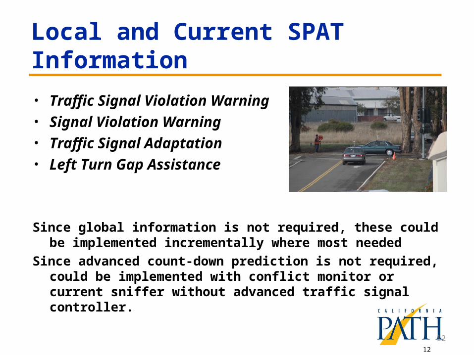
Local and Current SPAT Information
• Traffic Signal Violation Warning• Signal Violation Warning• Traffic Signal Adaptation• Left Turn Gap Assistance
Since global information is not required, these could be implemented incrementally where most needed
Since advanced count-down prediction is not required, could be implemented with conflict monitor or current sniffer without advanced traffic signal controller.
12
13
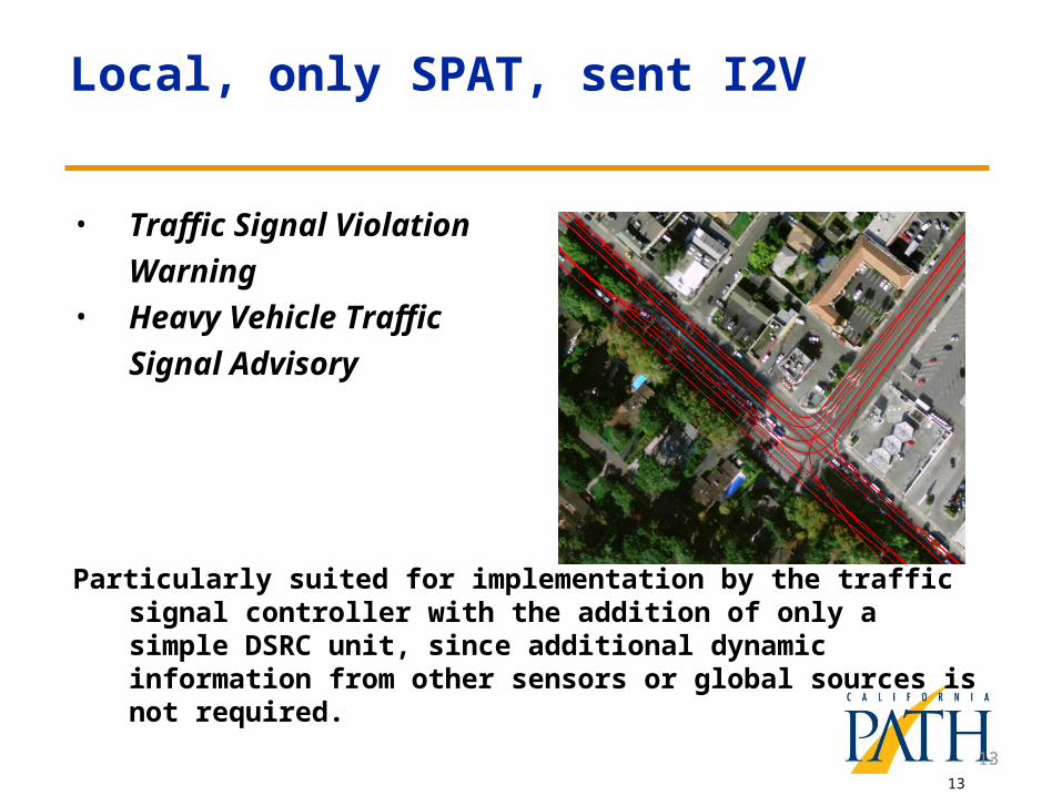
Local, only SPAT, sent I2V
• Traffic Signal Violation
Warning• Heavy Vehicle Traffic
Signal Advisory
Particularly suited for implementation by the traffic signal controller with the addition of only a simple DSRC unit, since additional dynamic information from other sensors or global sources is not required.
13

14
Global Information, Bidirectional Communication
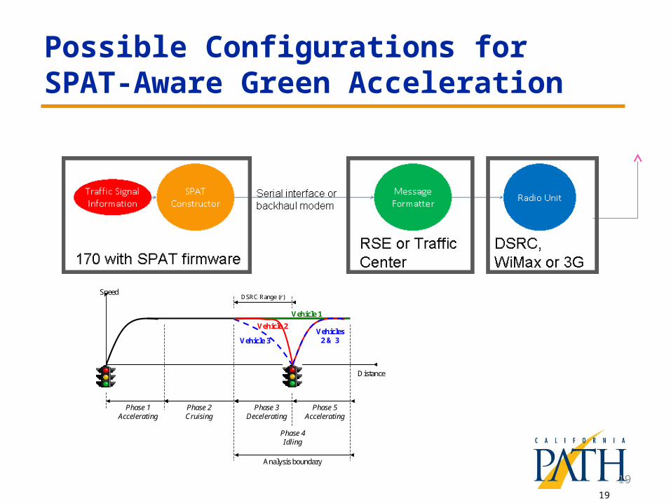
• SPAT-Aware Navigation• Dynamic Transit Arrival Time Prediction• Transit Signal Priority• SPAT-Aware Green Acceleration
Particularly suited for initial implementation using traffic signal information already being sent to traffic management centers, and possibly 4G communications, if the latencies are found to be tolerable. As more cars become enabled for these applications, the latencies may grow and require DSRC implementation.
14
15
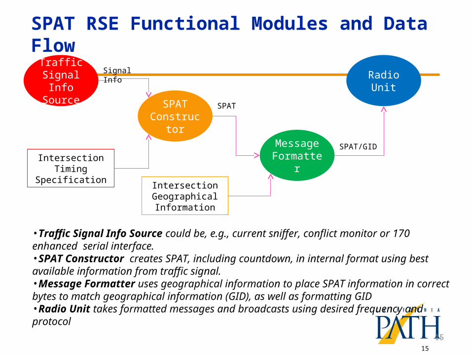
SPAT RSE Functional Modules and Data Flow
Signal Info
Intersection Timing Specification
SPAT
•Traffic Signal Info Source could be, e.g., current sniffer, conflict monitor or 170 enhanced serial interface.•SPAT Constructor creates SPAT, including countdown, in internal format using best available information from traffic signal.•Message Formatter uses geographical information to place SPAT information in correct bytes to match geographical information (GID), as well as formatting GID•Radio Unit takes formatted messages and broadcasts using desired frequency and protocol
SPAT Constructo
r
Traffic Signal Info
Source
Message Formatter
Intersection Geographical Information
Radio Unit
SPAT/GID
15
16
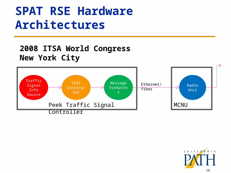
SPAT RSE Hardware Architectures
SPAT Constructor
Traffic Signal Info
Source
Message Formatter
Peek Traffic Signal Controller
Radio Unit
MCNU
Ethernet/fiber
2008 ITSA World Congress New York City
17
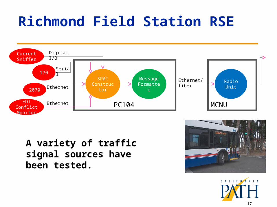
Richmond Field Station RSE
SPAT Constructor
Current Sniffer
Message Formatter
PC104
Radio Unit
MCNU
Ethernet/fiber
170
Digital I/O
Serial
2070
EDI Conflict Monitor
Ethernet
Ethernet
A variety of traffic signal sources have been tested.
18
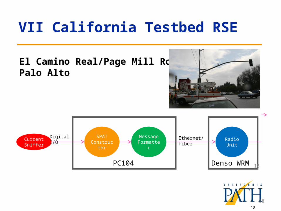
VII California Testbed RSE
18
El Camino Real/Page Mill Road, Palo Alto
SPAT Constructor
Current Sniffer
Message Formatter
PC104
Radio Unit
Denso WRM
Ethernet/fiberDigital I/O
18
19
Possible Configurations for SPAT-Aware Green Acceleration
19
Distance
Speed
Vehicle 1
Vehicle 2
Vehicle 3 Vehicles
2 & 3
Phase 1 Accelerating
Phase 3 Decelerating
Phase 5 Accelerating
Phase 2 Cruising
Phase 4 Idling
Analysis boundary
DSRC Range (r)
20
Steps to Deploying Individual SPAT RSE
• Top level activities (some in parallel)– Testing for radio and computer system performance and
reliability– Testing of interface to traffic signal controllers for
enhanced SPAT information– Development of J2735-compatible SPAT format and
associated GID– Vehicle reception of new SPAT format– On-site installation of RSE– On-site installation of controller interface– Calibration of accurate Map/GID (for each intersection,
requires vehicle testing)– On-site broadcast of enhanced SPAT/Map (GID)
20

21
Questions?
THANK YOU
Jim MisenerCalifornia PATH Program, University of
California, Berkeley