1. report no. - home - department of civil, architectural … 3.6 shear stress versus displacement...
TRANSCRIPT
Technical Report Documentation Page 1. Report No.
FHWA/TX-06/5-9023-01-1 2. Government Accession No.
3. Recipient’s Catalog No.
5. Report Date August 2005; Revised February 2006
4. Title and Subtitle Engineering Properties of Tire Bales for Soil Repairs and Embankment Construction 6. Performing Organization Code
7. Author(s) Jorge G. Zornberg, Christopher J. LaRocque
8. Performing Organization Report No. 5-9023-01-1
10. Work Unit No. (TRAIS) 9. Performing Organization Name and Address Center for Transportation Research The University of Texas at Austin 3208 Red River, Suite 200 Austin, TX 78705-2650
11. Contract or Grant No. 5-9023-01
13. Type of Report and Period Covered Technical Report February 2004–August 2005
12. Sponsoring Agency Name and Address Texas Department of Transportation Research and Technology Implementation Office P.O. Box 5080 Austin, TX 78763-5080
14. Sponsoring Agency Code
15. Supplementary Notes Project performed in cooperation with the Texas Department of Transportation and the Federal Highway Administration. Project Title: Validation of the Effectiveness of Tire Bale Use in Slope Repairs and Embankment Construction
16. Abstract This report summarizes the results of tasks conducted to characterize the properties of tire bales for use in limit equilibrium stability analyses. The test results indicate that the use of tire bales is a promising alternative for slope stabilization.
17. Key Words tires, waste, bales, stabilization, slopes, stability
18. Distribution Statement No restrictions. This document is available to the public through the National Technical Information Service, Springfield, Virginia 22161; www.ntis.gov.
19. Security Classif. (of report) Unclassified
20. Security Classif. (of this page) Unclassified
21. No. of pages 42
22. Price
Form DOT F 1700.7 (8-72) Reproduction of completed page authorized


Engineering Properties of Tire Bales for Soil Repairs and Embankment Construction Jorge G. Zornberg, Ph.D., P.E. Christopher J. LaRocque CTR Technical Report: 5-9023-01-1 Report Date: August 2005; Revised February 2006 Research Project: 5-9023-01 Research Project Title: Validation of the Effectiveness of Tire Bale Use in Slope Repairs and
Embankment Construction Sponsoring Agency: Texas Department of Transportation Performing Agency: Center for Transportation Research at The University of Texas at Austin Project performed in cooperation with the Texas Department of Transportation and the Federal Highway Administration.

iv
Center for Transportation Research The University of Texas at Austin 3208 Red River Austin, TX 78705 www.utexas.edu/research/ctr Copyright (c) 2006 Center for Transportation Research The University of Texas at Austin All rights reserved Printed in the United States of America

v
Disclaimers Author’s Disclaimer: The contents of this report reflect the views of the authors, who
are responsible for the facts and the accuracy of the data presented herein. The contents do not necessarily reflect the official view or policies of the Federal Highway Administration or the Texas Department of Transportation (TxDOT). This report does not constitute a standard, specification, or regulation.
Patent Disclaimer: There was no invention or discovery conceived or first actually reduced to practice in the course of or under this contract, including any art, method, process, machine manufacture, design or composition of matter, or any new useful improvement thereof, or any variety of plant, which is or may be patentable under the patent laws of the United States of America or any foreign country.
Notice: The United States Government and the State of Texas do not endorse products or manufacturers. If trade or manufacturers’ names appear herein, it is solely because they are considered essential to the object of this report.
Engineering Disclaimer NOT INTENDED FOR CONSTRUCTION, BIDDING, OR PERMIT PURPOSES.
Project Engineer: Jorge G. Zornberg
Professional Engineer License: California, No. C 056325 P. E. Designation: Research Supervisor
vi
Acknowledgments The implementation was sponsored by the Texas Department of Transportation. The
Project Director was Richard Williammee, P.E. His help, guidance and enthusiasm with the project is gratefully acknowledged. The help of Chunling Li, John McCartney, Gustavo Leite, and TxDOT personnel from the Fort Worth and Austin Districts is also gratefully acknowledged.
Products Draft specifications for use of tire bales in slope stabilization (P1) are provided in this
report as Appendix A.

vii
Table of Contents 1. Introduction................................................................................................................................. 1 2. Background Information............................................................................................................. 1 3. Experimental Testing Program ................................................................................................... 3
3.1 Characterization of Dimensions and Unit Weight of Tire Bales...........................................3 3.2 Determination of Interface Shear Strength of Tire Bales......................................................5 3.3 Evaluation of Rebound and Expected Expansive Pressure ...................................................9 3.4 Quantification of Time-Dependent Deformations under Sustained Load...........................10
4. Field Evaluation Program ......................................................................................................... 12 4.1 Design of Monitoring Program ...........................................................................................12 4.2 Instrumentation Procurement ..............................................................................................12 4.3 Field Inspection ...................................................................................................................14 4.4 Analytical Evaluation ..........................................................................................................14
5. Conclusions and Recommendations ......................................................................................... 15 5.1 Conclusions .........................................................................................................................15 5.2 The Path Forward ................................................................................................................15
References ..................................................................................................................................... 17 Appendix A: Draft Specifications................................................................................................. 19
A.1 Draft Specifications to Incorporate the Use of Tire Bales in Embankment Construction (TxDOT 2005) .......................................................................19
A.2 Recommended Modifications to Draft Specifications .......................................................28 A.3 Additional Considerations ..................................................................................................31

viii

ix
List of Figures Figure 2.1 Use of tire bales for slope stabilization ........................................................................2 Figure 3.1 View of one of the tire bales used in the experimental testing program......................3 Figure 3.2 Location of standardized measurements for width (W), length (L),
and height (H) of tire bales..........................................................................................4 Figure 3.3 Procedure for determination of submerged weight of tire bales ..................................5 Figure 3.4 Direct shear testing equipment at The University of Texas at Austin:
(a) schematic side view; (b) side view .........................................................................7 Figure 3.5 Rolling connection for vertical actuator and reaction beam.........................................8 Figure 3.6 Shear stress versus displacement results obtained in a typical direct shear test...........8 Figure 3.7 Shear strength envelope for tire bales ..........................................................................9 Figure 3.8 Expansion of tire bale after breakage of all wires ......................................................10 Figure 3.9 Testing setup for compressibility and creep testing of tire bales ...............................11 Figure 3.10 Results obtained from compressibility tests conducted without
the use of confining straps..........................................................................................11 Figure 4.1 Layout of instrumentation for evaluation of thermal response of
slope reinforced using tire bales.................................................................................13
List of Tables Table 2.1 Estimated US waste tire market in 2001 (in millions of tires, % of total).................... 3 Table 4.1 Instrumentation list for monitoring program .............................................................. 13

1
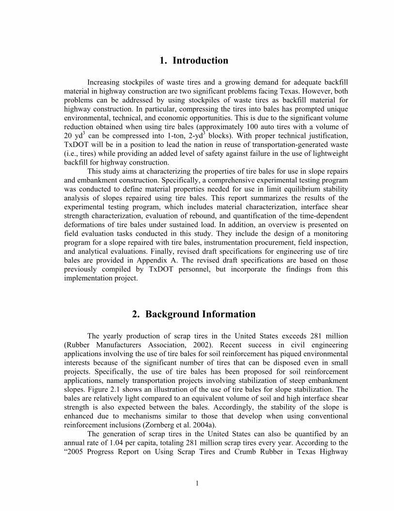
1. Introduction
Increasing stockpiles of waste tires and a growing demand for adequate backfill material in highway construction are two significant problems facing Texas. However, both problems can be addressed by using stockpiles of waste tires as backfill material for highway construction. In particular, compressing the tires into bales has prompted unique environmental, technical, and economic opportunities. This is due to the significant volume reduction obtained when using tire bales (approximately 100 auto tires with a volume of 20 yd3 can be compressed into 1-ton, 2-yd3 blocks). With proper technical justification, TxDOT will be in a position to lead the nation in reuse of transportation-generated waste (i.e., tires) while providing an added level of safety against failure in the use of lightweight backfill for highway construction.
This study aims at characterizing the properties of tire bales for use in slope repairs and embankment construction. Specifically, a comprehensive experimental testing program was conducted to define material properties needed for use in limit equilibrium stability analysis of slopes repaired using tire bales. This report summarizes the results of the experimental testing program, which includes material characterization, interface shear strength characterization, evaluation of rebound, and quantification of the time-dependent deformations of tire bales under sustained load. In addition, an overview is presented on field evaluation tasks conducted in this study. They include the design of a monitoring program for a slope repaired with tire bales, instrumentation procurement, field inspection, and analytical evaluations. Finally, revised draft specifications for engineering use of tire bales are provided in Appendix A. The revised draft specifications are based on those previously compiled by TxDOT personnel, but incorporate the findings from this implementation project.
2. Background Information
The yearly production of scrap tires in the United States exceeds 281 million (Rubber Manufacturers Association, 2002). Recent success in civil engineering applications involving the use of tire bales for soil reinforcement has piqued environmental interests because of the significant number of tires that can be disposed even in small projects. Specifically, the use of tire bales has been proposed for soil reinforcement applications, namely transportation projects involving stabilization of steep embankment slopes. Figure 2.1 shows an illustration of the use of tire bales for slope stabilization. The bales are relatively light compared to an equivalent volume of soil and high interface shear strength is also expected between the bales. Accordingly, the stability of the slope is enhanced due to mechanisms similar to those that develop when using conventional reinforcement inclusions (Zornberg et al. 2004a).
The generation of scrap tires in the United States can also be quantified by an annual rate of 1.04 per capita, totaling 281 million scrap tires every year. According to the “2005 Progress Report on Using Scrap Tires and Crumb Rubber in Texas Highway

2
Construction Projects” (TxDOT, TCEQ 2005), Texans generate 24 million scrap tires each year, which is consistent with the national average of over one tire for every person residing in the state. In addition, an estimated 2 billion waste passenger car and truck tires are currently stockpiled across the nation. In Texas, the equivalent of approximately 43.4 million scrap tires lay on the ground (TxDOT, TCEQ 2005). Tires may not be “recycled” for use in vehicles because tires are manufactured using vulcanized rubber. Since tire rubber is a thermosetting polymer (i.e., cannot be heated to mold again), the rubber cannot be reformed into new tires. Instead, they must be reused or discarded.
Tire bales zone
Potential failure surface
Granular base
Soil cover and/or pavement surface
Tire bales zone
Potential failure surface
Granular base
Soil cover and/or pavement surface
Figure 2.1 Use of tire bales for slope stabilization
The specific focus of this project is to validate the use of whole tires compressed into bales, which is a relatively new approach for civil engineering applications when compared to the reuse of tires in the form of shredded tires. Tire baling provides an important advantage over shredded tires in that the potential for exothermic reactions is minimized. Tire bales also appear to provide economic advantages over the use of tire shreds in terms of production cost and ease of placement during construction. However, to date, comparatively little testing has been completed to quantify the engineering properties and the in-situ performance of tire bales used in civil engineering applications.
As shown in Table 2.1, the second leading means of waste tire disposal involves scrap tire products for non–civil-engineering projects such as punched, chipped, or shredded tires for playgrounds and running tracks. The third means of tire disposal (40 million waste tires) involves use of tires solely for civil engineering applications. This growing source for disposal as scrap tire products has significant advantages over the use of more conventional lightweight fill materials. Scrap tire materials (tire shreds and bales) are lightweight, free draining, and comparatively inexpensive, and provide low lateral pressure and low thermal conductivity. In addition, tire bales (the focus of this implementation project) involve a relatively inexpensive manufacturing process and are easy to install because they are compacted prior to delivery. As a consequence, tire bales have been reported to substantially reduce construction costs for large highway projects such as that in Chautauqua County, New York (Zornberg 2004a). The consumption of scrap tires from 2002 to 2003 is reported to have dropped more than 50 percent for civil

3
engineering projects (TxDOT, TCEQ 2005). Indeed, the consumption of tires for civil engineering projects has dropped from almost five million in year 2000 to approximately 1.7 million in 2003. This declining trend could be easily reversed by the use of tire bales in civil engineering projects as proposed herein.
Table 2.1 Estimated US waste tire market in 2001 (in millions of tires, % of total)
Type Quantity
(millions of tires) %
Generation Tire Derived Fuel (TDF) 115 40.93%
Scrap Tire Products 41 14.59%
Civil Engineering 40 14.23%
Exported 15 5.34%
Miscellaneous 7 2.49%
TOTAL USE 218 77.58%
TOTAL GENERATION 281 100.00%
3. Experimental Testing Program
3.1 Characterization of Dimensions and Unit Weight of Tire Bales Tire bales are manufactured using a tire-baling machine, which compresses
approximately 100 waste auto tires into a 2-cubic-yard, 1-ton bale (1.5 m3, 0.9 metric ton). Each bale is fastened with galvanized or stainless steel baling wire (Encore Systems, Inc. 2000). Tire baling results in an approximate 5:1 volume reduction. Figure 3.1 shows one of the tire bales used in the experimental testing program conducted as part of this study.
Figure 3.1 View of one of the tire bales used in the experimental testing program

4
Procedures for measurement of the tire bale dimensions were developed and implemented as part of this study. The procedure involved measurement of the tire bale dimensions in 16 locations (LaRocque 2005). The measurements are averaged to define the width (W), length (L), and height (H) of each tire bale in a consistent manner. Figure 3.2 shows the locations used in this study to define the dimensions of the tire bale. The procedure is considered to be suitable for implementation in specifications and future evaluation of variability of tire bale dimensions. The average dimensions of the tire bales used in this investigation are as follows:
• Tire bale width: 5.13 ± 0.3 ft • Tire bale length: 4.65 ± 0.3 ft • Tire bale height: 2.41 ± 0.2 ft • Tire bale volume: 57.43 ± 5 ft3
Figure 3.2 Location of standardized measurements for width (W), length (L), and height (H) of tire bales
The average weight of a waste automobile tire is 20 lb (89 N) while the average weight of a truck tire is 100 lb (445 N). This study also characterized the unit weight of tire bales manufactured using automobile tires. This required the development of procedures involving submersion of the tire bales into water and determination of the submerged total
L-1
L-5
W-2
L-2
W-1
L-6
W-6
W-5
W-3
L-3
W
LH
H-1
H-2
H-3
H-4
L-4W-4
L-1
L-5
W-2
L-2
W-1
L-6
W-6
W-5
W-3
L-3
W
LH
W
LH
H-1
H-2
H-3
H-4
L-4W-4
5
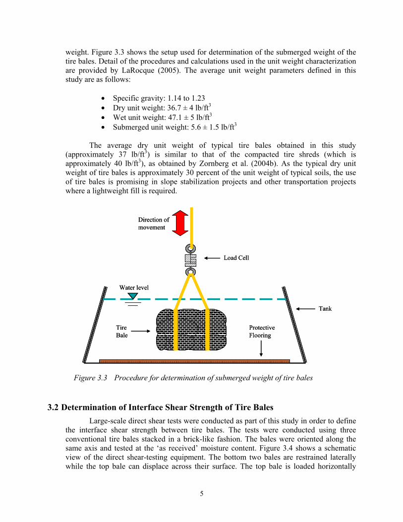
weight. Figure 3.3 shows the setup used for determination of the submerged weight of the tire bales. Detail of the procedures and calculations used in the unit weight characterization are provided by LaRocque (2005). The average unit weight parameters defined in this study are as follows:
• Specific gravity: 1.14 to 1.23 • Dry unit weight: 36.7 ± 4 lb/ft3 • Wet unit weight: 47.1 ± 5 lb/ft3 • Submerged unit weight: 5.6 ± 1.5 lb/ft3
The average dry unit weight of typical tire bales obtained in this study
(approximately 37 lb/ft3) is similar to that of the compacted tire shreds (which is approximately 40 lb/ft3), as obtained by Zornberg et al. (2004b). As the typical dry unit weight of tire bales is approximately 30 percent of the unit weight of typical soils, the use of tire bales is promising in slope stabilization projects and other transportation projects where a lightweight fill is required.
Figure 3.3 Procedure for determination of submerged weight of tire bales
3.2 Determination of Interface Shear Strength of Tire Bales Large-scale direct shear tests were conducted as part of this study in order to define
the interface shear strength between tire bales. The tests were conducted using three conventional tire bales stacked in a brick-like fashion. The bales were oriented along the same axis and tested at the ‘as received’ moisture content. Figure 3.4 shows a schematic view of the direct shear-testing equipment. The bottom two bales are restrained laterally while the top bale can displace across their surface. The top bale is loaded horizontally
Load Cell
Tire Bale
Protective Flooring
Tank
Direction of movement
Water level
Load Cell
Tire Bale
Protective Flooring
Tank
Direction of movement
Water level

6
using a high capacity actuator, which is statically mounted on a reaction column. The normal (vertical) load is applied using a second actuator mounted directly to a steel bearing plate attached to the top of the bale. A roller assembly reacting against a load bearing I-beam allows displacement of the vertical actuator along with the top tire bale during testing. A steel bearing plate is placed on the two loaded faces of the sliding bale to distribute the load applied by the respective actuators. A load cell is used to measure the load applied by the horizontal actuator. The linear potentiometers placed at the front and back of the top bale measure the horizontal displacement. Preliminary tests have shown that the top bale may experience a “rocking” motion due to the irregularities in the bales and the high interface shear strength in concentrated areas. This was resolved by placing the horizontal actuator towards the lower portion of the top bale.
The new direct shear system for testing tire bales is located at The University of Texas at Austin. A key component of the testing setup is the rolling connection used to transfer the normal load during testing. This system was specifically designed to accommodate the large displacements (a couple of feet) that can take place during testing (Figure 3.5). This component was crucial to the success of direct shear tests conducted in this project. Specifically, three tire bales will be stacked vertically in this test, with the upper and lower bales being restrained from moving laterally. The normal load will be applied, and the top bale will be displaced horizontally. A number of different normal stresses, representative of the working stresses under field conditions, were adopted in the testing program. The load required to pull the bale out was recorded and reported for each vertical stress while shear displacements were recorded.
Typical results from one of the direct shear tests are shown in Figure 3.6. The figure shows the horizontal shear stress as a function of shear displacements for a test conducted under a normal stress of 1.41 psi. Note that the horizontal shear stress required to shear the bale reaches a maximum of approximately 2.7 psi, a stress level that is labeled as “Failure” in the figure, and then continues to increase after a short stabilization. Regardless of the applied normal (vertical) stress, all direct shear tests conducted in this study showed a similar trend. The results for the additional direct shear tests are provided by LaRocque (2005).
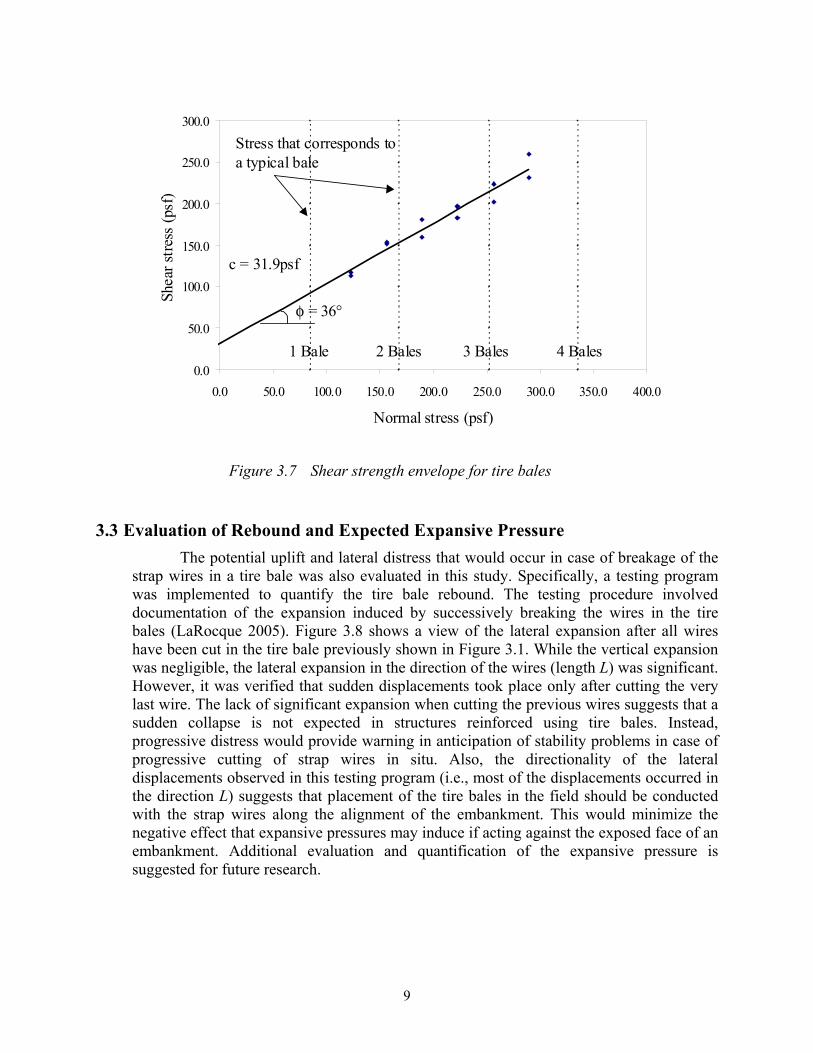
The failure point observed in the test results was used to define the shear strength envelopes for the purpose of this study. As shown in Figure 3.7, this is a conservative assumption since the shear strength may increase as much as 70 percent over this value. The shear strength envelope that corresponds to the failure points of 16 tests conducted for this study is shown in Figure 3.7 as a function of the applied normal stress. The test results define the interface failure envelope of the tire bale composites. The interface shear strength parameters (c and φ) can be determined from linear regression of these test results as c = 31.9 psf and φ = 36°. The variability of these test results, the effect of moisture at the interface, the effect of directionality of tire bale placement, and the potential use of intermediate soil layers between tire bales were not evaluated as part of this study. While additional evaluation for the various conditions is recommended for future testing programs, it may be concluded that the interface shear strength of tire bales is comparatively high. This makes the use of tire bales a suitable alternative for slope stabilization projects.

7
Figure 3.4 Direct shear testing equipment at The University of Texas at Austin: (a) schematic side view; (b) side view
(a)
Linear Potentiometer
Linear Potentiometer
Load Frame
Vertical Actuator
Horizontal Actuator
Load Cell
Rolling System for Vertical Actuator
Stationary Tire Bales
Steel Bearing Plate
Reaction Column for Horizontal Load
Reaction Beam for Rolling Vertical Load
Data Acquisition System
Sliding Tire Bale
Linear Potentiometer
Linear Potentiometer
Load Frame
Vertical Actuator
Horizontal Actuator
Load Cell
Rolling System for Vertical Actuator
Stationary Tire Bales
Steel Bearing Plate
Reaction Column for Horizontal Load
Reaction Beam for Rolling Vertical Load
Data Acquisition System
Sliding Tire Bale
(b)
Sliding Tire Bale
Rolling System for Vertical Actuator
Reaction Beam for Rolling Vertical Load
Load Frame
Vertical Actuator
Horizontal Actuator
Reaction Column for Horizontal Load
Steel Bearing Plate
Stationary Tire Bales
Sliding Tire Bale
Rolling System for Vertical Actuator
Reaction Beam for Rolling Vertical Load
Load Frame
Vertical Actuator
Horizontal Actuator
Reaction Column for Horizontal Load
Steel Bearing Plate
Stationary Tire Bales

8
Figure 3.5 Rolling connection for vertical actuator and reaction beam
0
0.5
1
1.5
2
2.5
3
3.5
4
4.5
5
0 2 4 6 8 10 12 14
Horizontal Displacement (inches)
Shea
r Stre
ss (p
si)
Failure
Back displacement
Front displacement
0
0.5
1
1.5
2
2.5
3
3.5
4
4.5
5
0 2 4 6 8 10 12 14
Horizontal Displacement (inches)
Shea
r Stre
ss (p
si)
Failure
Back displacement
Front displacement
Figure 3.6 Shear stress versus displacement results obtained in a typical direct shear test
Vertical Actuator
Rollers
Reaction Beam
Vertical Actuator
Rollers
Reaction Beam
9
0.0
50.0
100.0
150.0
200.0
250.0
300.0
0.0 50.0 100.0 150.0 200.0 250.0 300.0 350.0 400.0
Normal stress (psf)
Shea
r stre
ss (p
sf)
c = 31.9psf
φ = 36°
Stress that corresponds to a typical bale
1 Bale 2 Bales 3 Bales 4 Bales0.0
50.0
100.0
150.0
200.0
250.0
300.0
0.0 50.0 100.0 150.0 200.0 250.0 300.0 350.0 400.0
Normal stress (psf)
Shea
r stre
ss (p
sf)
c = 31.9psf
φ = 36°
Stress that corresponds to a typical bale
1 Bale 2 Bales 3 Bales 4 Bales
Figure 3.7 Shear strength envelope for tire bales
3.3 Evaluation of Rebound and Expected Expansive Pressure The potential uplift and lateral distress that would occur in case of breakage of the
strap wires in a tire bale was also evaluated in this study. Specifically, a testing program was implemented to quantify the tire bale rebound. The testing procedure involved documentation of the expansion induced by successively breaking the wires in the tire bales (LaRocque 2005). Figure 3.8 shows a view of the lateral expansion after all wires have been cut in the tire bale previously shown in Figure 3.1. While the vertical expansion was negligible, the lateral expansion in the direction of the wires (length L) was significant. However, it was verified that sudden displacements took place only after cutting the very last wire. The lack of significant expansion when cutting the previous wires suggests that a sudden collapse is not expected in structures reinforced using tire bales. Instead, progressive distress would provide warning in anticipation of stability problems in case of progressive cutting of strap wires in situ. Also, the directionality of the lateral displacements observed in this testing program (i.e., most of the displacements occurred in the direction L) suggests that placement of the tire bales in the field should be conducted with the strap wires along the alignment of the embankment. This would minimize the negative effect that expansive pressures may induce if acting against the exposed face of an embankment. Additional evaluation and quantification of the expansive pressure is suggested for future research.

10
Original Length of Tire BaleOriginal Length of Tire Bale
Figure 3.8 Expansion of tire bale after breakage of all wires
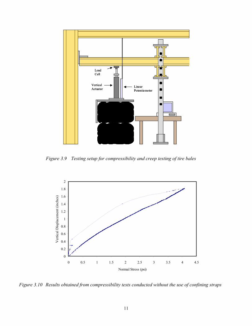
3.4 Quantification of Time-Dependent Deformations under Sustained Load The compressibility of tire bales and the time-dependent deformations (creep) of
tire bales were also evaluated as part of this study. Figure 3.9 shows a typical setup for compressibility and vertical creep configuration. In addition, creep under sustained shear was also evaluated using a setup consistent with that shown in Figure 3.3. Creep tests were conducted by evaluating the time-dependent deformations under sustained load both for shear and compressive loading modes. Details on the experimental testing procedures and the results of compressibility and creep tests are provided by LaRocque (2005). Evaluations were conducted to assess the effect of tire bale layout on compressibility results. In addition, the effect of the presence of adjacent tire bales (confinement) on compressibility results was also evaluated qualitatively by placing confining straps around the tire bales during testing. Figure 3.10 shows the results of one of the compressibility tests. As indicated in the figure, the response is linear up to stress levels that are well beyond those expected in typical transportation applications. Test results also indicate that the compressibility increases when tire bales are tested in a bricklike fashion and that compressibility decreases when the tests are conducted using confining straps to simulate the presence of adjacent tire bales.
11
Load Cell
Vertical Actuator
Linear Potentiometer
Load Cell
Vertical Actuator
Linear Potentiometer
Figure 3.9 Testing setup for compressibility and creep testing of tire bales
0
0.2
0.4
0.6
0.8
1
1.2
1.4
1.6
1.8
2
0 0.5 1 1.5 2 2.5 3 3.5 4 4.5
Normal Stress (psi)
Ver
tical
Dis
plac
emen
t (in
ches
)
Figure 3.10 Results obtained from compressibility tests conducted without the use of confining straps

12
4. Field Evaluation Program
4.1 Design of Monitoring Program The Implementation Director for this project made a considerable effort in trying to
identify a suitable project for remediation and possible instrumentation. However, no slope remediation project became available for a potential monitoring program throughout the duration of this implementation project. Accordingly, a monitoring program was designed, but not materialized during the extent of this project. Nonetheless, evaluations were conducted on the potential monitoring programs that could be implemented by TxDOT in case a slope stabilization project becomes available after completion of this project. Zornberg et al. (2005) summarized a series of instrumentation alternatives that include survey, visual observation, and monitoring of internal displacements using slope inclinometers and settlement plates. These instrumentation devices were considered in a slope repair project that became available toward the end of this implementation project (repair in IH 30, near Fort Worth). This project is currently being instrumented using vertical inclinometers. In addition, a monitoring program was designed to evaluate the thermal response of tire bales. A schematic view of the instrumentation layout is presented in Figure 4.1. The instruments for this monitoring program were procured as part of this project.
4.2 Instrumentation Procurement The list of instruments to be purchased at a future date was compiled as part of this
project. The monitoring layout is illustrated in Figure 4.1. The focus of this specific monitoring program was on the thermal evaluation of a slope stabilized using tire bales along Interstate Highway 30 near Fort Worth. Several alternatives were evaluated considering cost and technical requirements. The recommended alternative is presented in Table 4.1 (costs as of May 2005). The intent was to quantify the fire potential of tire bales against the known potential of tire shreds.

13
Figure 4.1 Layout of instrumentation for evaluation of thermal response of slope reinforced using tire bales
Table 4.1 Instrumentation list for monitoring program
Cost Quantity SubtotalTemperature (Internal and Ambient) MonitoringThermistor Model 107-L (Campbell Scientific) 70.00$ 20 1,400.00$ 50 feet of WIR CA 22AWG cable 0.26$ 1000 260.00$
Soil Moisture MonitoringCS616-L Water Content Reflectometer 150.00$ 20 3,000.00$ Sensor Cable: 25, 50, 75, 100 feet recommended 0.68$ 500 340.00$
Relative Humidity and Temperature MonitoringCS500 (Campbell Scientific; modified version of the Vaisala 50Y Humitter) 335.00$ 20 6,700.00$ 50 feet of WIR CA 22 AWG cable 0.47$ 1000 470.00$
Data CollectionCR10X Datalogger (Campbell Scientific) 1,250.00$ 1 1,250.00$
AM16/32 16-channel or 32-channel relay Multiplexer (Campbell Scientific) 545.00$ 1 545.00$
(41303) 6-Plate Gill Radiation Shield (Campbell Scientific) 100.00$ 1 100.00$
MSX20R 20-Watt Solar Panel w/ Mounts 10ft lead (Campbell Scientific) 365.00$ 1 365.00$
12V Regulated Power Supply 210.00$ 1 210.00$
ENC 12/14 Enclosure 195.00$ 1 195.00$ Single-notch brackets for CM6/10 or UT30 35.00$ 1 35.00$
Total 14,870.00$
Data Acquisition System
Tire Bales
Granular Base
Soil Moisture Sensor Soil Temperature Sensor
BackfillSoil
Data Acquisition System
Tire Bales
Granular Base
Soil Moisture Sensor Soil Temperature Sensor
BackfillSoil
14
4.3 Field Inspection The initial motivation for this implementation project stems from a TxDOT slope
repair project that involved the use of recycled tire bales for a slope failure repair along Interstate Highway 30, east of Fort Worth. The slope had previously failed twice in the same location due to above-average rainfall. Remediation of this slope failure, carried out in 2002, began with the placement of delivered tire bales at the toe of the slope. Once the bales were secured, the slope was completely covered with soil, followed by reshaping of the slope. Compost and seed were spread to stimulate vegetation growth and minimize future surface slope erosion (TxDOT, TCEQ 2003). Within 8 months of the placement of the first bales, the Fort Worth area had received nearly 50 inches of rainfall. A site visit and a preliminary slope stability analysis revealed that the use of tire bales in place of the original soil slope had improved the stability of the slope while using 360 recycled tire bales, totaling about 36,000 scrap tires (TxDOT, TCEQ 2003). A second field inspection was conducted as part of this implementation project in April 2005 in order to reevaluate the slope performance. Documentation of such inspection is provided by LaRocque (2005). The observations indicate an excellent performance of the slope. However, based on observations conducted on the failed unreinforced slope adjacent to the tire bale project, it became apparent that appropriate drainage (e.g., a basal drainage blanket) needs to be considered in all projects involving stabilization of fine grained soils. The lack of an appropriate drainage system in the IH 30 project led to destabilization of the adjacent structures. In fact, excavation of the slope adjacent to the zone reinforced with tire bales revealed that a significant storage of water (estimated at over 2,000 gal) had taken place within the tire bales due to the lack of appropriate drainage.
4.4 Analytical Evaluation An engineering study had been conducted for TxDOT by TEAM Consultants, Inc.
to analyze and document the use of tire bales for the slope repair along IH 30 documented in Section 4.3 (Team Consultants, Inc. 2003). However, assumptions were needed during that evaluation regarding the shear strength properties of the tire bales used in the stability analyses conducted using the UTEXAS program. The use of creative approaches to solve problems in spite of lacking information is not uncommon in geotechnical engineering, which has been labeled as being largely reactive (Mitchell 1999); that is, experience, practice, and the introduction of new construction technologies have often led theory and complete understanding of engineering problems. Accordingly, this implementation project was initiated to validate the shear strength values assumed in the design. Analyses were conducted as part of this implementation project using the same limit equilibrium program (UTEXAS) used by Team Consultants (2003). The results indicated good agreement with the factor of safety obtained in the engineering study for the case of unreinforced slope (a slope with a safety factor of approximately 1.0 for adverse water level conditions). Based on the findings of this study, a limit equilibrium analysis was subsequently conducted of the slope stabilized using tire bales. The analysis, conducted using the interface shear strength values obtained in this study and imposing wedge failure surfaces, which does not allow interception of the tire bales, led to a significantly higher factor of safety. Specifically, a safety factor of 2.40 was obtained for adverse water level conditions.

15
5. Conclusions and Recommendations
5.1 Conclusions A comprehensive validation plan was conducted as part of this implementation
project in order to validate the effectiveness of using tire bales in slope repair and embankment construction projects. A comprehensive experimental testing program and a field evaluation program were conducted as part of this study. The main conclusions that can be drawn from this project are as follows:
• Tire bales have high interface shear strength that can be characterized by a
negligible cohesion and a friction angle of 36 degrees. • The unit weight of tire bales is approximately 45 pcf. • Time-dependent deformations can take place under both shear and
compressive modes. • Compressibility of tires is significantly higher than that of soils. However, it
includes a significant elastic component. • Breakage of wires leads to sudden expansion only after all wires have been
cut. Engineering alternatives (e.g., selection of the appropriate orientation of the bales during construction) can be considered to account for such an event.
• The use of appropriate drainage (e.g., a drainage blanket) is imperative. • The orientation of tire bales should be decided based on hydraulic and
mechanical considerations. • The use of tire bales for slope stabilization projects can lead to a significant
increase in the overall stability as observed by: o The comparatively high interface shear strength of tire bales o The comparatively low unit weight of tire bales o The limit equilibrium analysis of slopes that should be characterized
by wedge-type analyses o The observed performance of stabilized slopes even if subjected to
unusually high volumes of water
The findings of this implementation project were incorporated into draft specifications, as presented in Appendix A.
5.2 The Path Forward This study has confirmed that the use of tire bales is not only feasible, but that the
mechanical properties may be better than initially envisioned. However, considering the novelty of this approach, the assessment of material properties for tire bales requires further evaluation. This is also because of the significant volume of tire bales, which requires the use of large-scale, non-conventional equipment for testing. Accordingly, additional characterization of tire bale properties is still needed to complete the development of design recommendations and guidelines. This is also expected to include assessment of the
16
variability of the mechanical properties and of the sensitivity of those properties to different bale configurations, the presence of infill, and moisture conditions. Accordingly, recommendations for further evaluation regarding the use of tire bales in slope repair projects include:
• Refinement of analytical framework for analysis • Assessment of the effects of the presence of intermediate soil layers, the tire
bale orientation, and the presence of water on the interface shear strength properties
• Hydraulic characterization of tire bales, including evaluation of the response of tire bales under submerged conditions
• Thermal assessment of tire bales • Quantification of time-dependent deformations under different loading
modes (shear, compression) • Identification of proper analysis programs to best define the potential failure
planes • Integration of the use of tire bales, which provides stability against deep
seated failures, with complementary stabilization techniques suitable for remediation of shallow (surficial) failures
• Proper analysis programs to best define the potential failure planes.
17
References
Encore Systems, Inc. (2000). http://www.tirebaler.com
LaRocque, C. J. (2005). Evaluation of Tire Bales for Use in the Repair of Slopes in Transportation Projects. Department of Civil, Architectural, and Environmental Engineering, The University of Texas at Austin, in preparation.
Mitchell, J. K. (1999). “Education in Geotechnical Engineering—Its evolution, current status, and challenges for the 21st Century.” Proceedings of the Eleventh Pan-American Conference on Soil Mechanics and Foundation Engineering, August 1999, Iguaçu Falls, Brazil, Volume 4, pp. 167–174.
Rubber Manufacturers Association, (2002). “U.S. Scrap Tire Markets 2001,” Rubber Manufacturers Association, Washington, D.C.
Team Consultants, Inc. (2003). Geotechnical Investigation and Analyses— Slope Failure Repair Utilizing Baled Tire Fill, Interstate Highway 30 west of Oakland Blvd., Fort Worth, Tarrant County, Texas. Report to Fort Worth District, Texas Department of Transportation, Fort Worth, Texas.
TxDOT (2005) http://www.dot.state.tx.us/GSD/recycle/tirebales.htm
TXDOT, TCEQ (2003). “Progress Report on Using Scrap Tires and Crumb Rubber in Highway Construction Projects,” 77th Legislative Session TCEQ-Rider 19 and TXDOT-Rider 44. Texas Department of Transportation, Texas Commission on Environmental Quality.
TxDOT, TCEQ (2005). “2005 Progress Report on Using Scrap Tires and Crumb Rubber in Texas Highway Construction Projects.” Submitted jointly by the Texas Commission on Environmental Quality and the Texas Department of Transportation.
Zornberg, J. G., Christopher, B. R., and LaRocque, C. J. (2004a). “Applications of Tire Bales in Transportation Projects.” Recycled Materials in Geotechnics, ASCE Geotechnical Special Publication No. 127, October 2004, Aydilek, A. H. and Wartman, J. (Editors), pp. 42–60.
Zornberg, J. G., Cabral, A., and Viratjandr, C. (2004b). “Behaviour of Tire Shred-Sand Mixtures for Use as Backfill Material.” Accepted for publication in the Canadian Geotechnical Journal.
Zornberg, J. G., Christopher, B. R., and Oosterbaan, M. D. (2005). Tire Bales in Highway Applications: Feasibility and Properties Evaluation. Colorado Department of Transportation, Report No. CDOT-DTD-R-2005-2, Denver, Colorado, 204 p.

18
19
Appendix A: Draft Specifications
This appendix provides recommended modifications to the draft specifications currently used by TxDOT regarding use of tire bales in embankment construction. The recommendations are provided as modifications to the draft specifications posted in the recycling program (TxDOT 2005). The preliminary nature of the recommendations provided in this appendix should be emphasized, as they are based on the limited experimental program conducted as part of implementation project 5-9023-01 “Validation of the Effectiveness of Tire Bale Use in Slope Repairs and Embankment Construction.” Section A.1 reproduces the current draft specifications in its entirety as reported by TxDOT (2005). Section A.2 presents the recommended modifications based on this study. This includes modifications to Item 132.2 (Material – Type E) and to Item 132.3 (Construction Methods – (c) Tire Bale Embankments).
A.1 Draft Specifications to Incorporate the Use of Tire Bales in Embankment Construction (TxDOT 2005) Note: red and blue text is reproduced from currently available TxDOT draft specifications.
ITEM 132
EMBANKMENT
132.1. Description. This Item shall govern for the placement and compaction of all materials necessary for the construction of roadway embankments, levees and dikes or any designated section of the roadway where additional material is required.
132.2. Material. Materials may be furnished from required excavation in the areas shown in the plans or from off-right-of-way sources obtained by the Contractor and meeting the requirements herein. All embankment shall conform to one of the following types as shown on the plans, except that material which is in a retaining-wall-backfill area shall meet the requirements for backfill material of the pertinent retaining-wall item:
Type A. This material shall consist of suitable granular material, free from
vegetation or other objectionable matter, and reasonably free from lumps of earth. This material shall be suitable for forming a stable embankment and, when tested in accordance with Test Methods Tex-104-E, Tex-105-E, Tex-106-E and Tex-107-E, Part II shall meet the following requirements:
The liquid limit shall not exceed 45 The plasticity index shall not exceed 15 The bar linear shrinkage shall not be less than 2
20
Type B. This material shall consist of suitable earth material such as rock, loam, clay, or other such materials, as approved by the Engineer, that will form a stable embankment.
Type C. This material shall be suitable and shall conform to the specification
requirements shown on the plans. Type D. This material shall be that obtained from required excavation areas shown
on the plans and will be used in embankment. . Type E. This material shall consist of tire bales made of whole, used passenger
vehicle tires or truck tires. Each bale shall contain only one type and size of tire, passenger or truck. The bales shall be produced in a tire baler or equivalent as approved by the Engineer. The tire baler shall be capable of compressing whole tires to reach a density not less than 35 lb/ft3. Each bale shall use a minimum of 3 galvanized steel or stainless steel straps or wires. The bales shall not “explode” when all the straps are broken or cut.
The size and weight of each tire bale should be approved by the Engineer. To be
eligible to supply tire bales to a project, the tire baler or the tire supplier shall be authorized to process waste tires by the Texas Natural Resource Conservation Commission.
The tire bales should be of uniform size within each project such that they can be
easily stacked to facilitate rapid construction.
The tire bales should be load tested with the bale fully supported on a test floor approved by the Engineer. During load testing, the bale should be sandwiched between two steel plates. The top steel plate on which the load is applied shall be 1 inch thick and its size should be identical to the loaded area of the bale. I-section steel shall be used to distribute the load uniformly over the steel plate, as approved by the Engineer. The load shall be applied using a hydraulic ram with a load capacity of at least 400,000 lbs.
Two types of strength tests, a creep test and a compressive strength test, shall be
conducted on tire bales. The creep test shall be conducted over 72 hours at a creep stress of 25 psi applied in the same direction along which loads are applied in the field. The maximum allowable creep strain shall not exceed 0.25. The compressive strength test shall be conducted until the tire bale fails or until an applied compressive stress of 100 psi, which ever is achieved first. In addition, the tire bales shall also have the following requirements:
The galvanized steel or stainless steel wires used as straps shall not break up to a
stress of 50 psi as applied on the tire bale surface. With regard to corrosion of these straps, requirements stipulated in Item 423.2 shall be met. Tire bale fills covered with geomembranes, which makes the tire fill impermeable to air and water, may not be subjected to the pH and resistivity requirements stipulated in Item 423.2.

21
Type F. This material shall consist of either 100 percent scrap tire chips (also referred to as shreds) or a blend of scrap tire chips and conventional embankment fill material of Types A or B indicated above. The tire chips shall be obtained by shredding used passenger vehicle tires or truck tires. Based on the composition of the embankment material, embankment fills are divided into three classes;
Class I fills are constructed using a blend of scrap tire chips and Type A or B
material. Tire chips in Class I fills shall be free of contaminants such as oil, grease, gasoline, diesel fuel, etc. that could create a fire hazard. Under no circumstances shall remains of tires subjected to a fire be used as a part of fill.
Class II fills are constructed either exclusively using tire chips or tire chips blended
with less than 30 percent Type A or B material. The maximum allowable thickness of Class II tire chip fills is 3 feet. Tire chips in Class II fills shall be free of contaminants such as oil, grease, gasoline, diesel fuel, etc. that could create a fire hazard. Under no circumstances shall remains of tires subjected to a fire be used as a part of fill. For Class II fills, tire shreds shall have a maximum of 50 percent (by weight) passing the 1.5-inch sieve and a maximum of five percent (by weight) passing the #4 sieve.
Class III fills are constructed exclusively using tire chips with a tire chip fill
thickness between 3 feet and 10 feet. No tire chip fill should be constructed exclusively with tire chips with tire chip layer thickness greater than 10 feet. Tire chips in Class III fills shall be free of contaminants such as oil, grease, gasoline, diesel fuel, etc. that could create a fire hazard. Under no circumstances shall remains of tires subjected to a fire be used as a part of fill. For Class III fills, tire chips shall have a maximum of 25 percent (by weight) passing the 1.5-inch sieve and a maximum of one percent (by weight) passing the #4 sieve. The tire chips shall be free from organic matter such as wood, wood chips and other fibrous organic matter. The tire chips shall have less than 1 percent (by weight) of metal fragments, which are not at least partially encased in rubber. Metal fragments that are encased partially in rubber shall protrude no more than 1 inch from the cut edge of the tire shred on 75 percent of the pieces and no more than 2 inches on 100 percent of the pieces.
Class III fills shall also be constructed such that infiltration of water and air is
minimized. Also, there shall be no direct contact between tire chips and soil containing organic matter, such as topsoil. A minimum of 18 inches thick mineral soil layer free of organic matter shall be placed and compacted over the tire chip fill. This mineral soil fill shall be separated from the tire chip fill by a geotextile to prevent the soil particles from washing into the voids in tire chip fill. For Class II fills, use of drainage features located at the bottom of the fill that could provide free access to air should be avoided. These drainage features may include, but not limited to open graded drainage layers on the side of the fill, and drainage holes in walls.
132.3. Construction Methods.
(1) General. When off-right-of-way sources are involved, the Contractor’s attention is directed to Item 7, Legal Relations and Responsibilities to the Public. Prior to

22
placing any embankment, all work in accordance with Item 100, “Preparing Right of Way,” shall have been completed on the areas over which the embankment is to be placed. Stump holes or other small excavations in the limits of the embankments shall be backfilled with suitable material and thoroughly tamped by approved methods before commencing embankment construction. The surface of the ground, including disk-loosened ground or any surface roughened by small washes or otherwise, shall be restored to approximately its original slope by blading or other methods. Where shown on the plans or required by the Engineer, the ground surface thus prepared shall be compacted by sprinkling and rolling.
The Engineer shall be notified sufficiently in advance of opening any material
source to allow performance of any required testing. Unless otherwise shown on the plans, the surfaces of unpaved areas (except rock)
that are to receive embankment shall be loosened by scarifying to a depth of at least 6 inches. Hillsides shall be cut into steps before embankment materials are placed. Placement of embankment materials shall begin at the low side of hillsides and slopes. Materials that have been loosened shall be recompacted simultaneously with the new embankment materials placed upon it. The total depth of loosened and new materials shall not exceed the permissible depth of the layer to be compacted, as specified in Subarticle 132.3.(3).(a) and (b).
Trees, stumps, roots, vegetation, or other unsuitable materials shall not be placed in
embankment.
Unless otherwise shown on the plans, all embankment shall be constructed in layers approximately parallel to the finished grade of the roadbed.
Embankments shall be constructed to the grade and sections shown on the plans or
as established by the Engineer. Each section of the embankment shall correspond to the detailed section or slopes established by the Engineer. After completion of the roadway, it shall be continuously maintained to its finished section and grade until the project is accepted.
(2) Constructing Embankments.
(a) Earth Embankments. Earth embankments shall be defined as those composed principally of material other than rock, and shall be constructed of acceptable material from approved sources.
Unless otherwise specified, earth embankments shall be constructed in successive
layers for the full width of the individual roadway cross section and in such lengths as are best suited to the sprinkling and compacting methods utilized.
A minor quantity of rock or broken concrete encountered in the construction of this
project may be incorporated in the lower layers of the embankment if acceptable to the Engineer. Or, it may be placed in the deeper fills, in accordance with the requirements for
23
the construction of rock embankments, provided such placement of rock is not immediately adjacent to structures or in areas where bridge foundations are to be constructed. Also, rock or broken concrete may be placed in the portions of embankments outside the limits of the completed roadbed width where the size of the rock or broken concrete prohibits its incorporation in the normal embankment layers. All exposed reinforced steel shall be cut and removed from the broken concrete.
Layers of embankment may be formed by utilizing equipment and methods that will
evenly distribute the material.
Each layer of embankment shall be uniform as to material, density, and moisture content before beginning compaction. Where layers of unlike materials abut each other, each layer shall be featheredged for at least 100 feet, or the material shall be so mixed as to prevent abrupt changes in the soil. No material placed in the embankment by dumping in a pile or windrow shall be incorporated in a layer in that position, but all such piles or windrows shall be moved by blading or similar methods. Clods or lumps of material shall be broken and the embankment material mixed by blading, harrowing, disking, or similar methods until a uniform material of uniform density is achieved in each layer.
Sprinkling required to achieve the moisture content necessary for compaction shall
meet the material requirements of Item 204, “Sprinkling.” It shall be the responsibility of the Contractor to secure a uniform moisture content throughout the layer by such methods as may be necessary. In order to facilitate uniform wetting of the embankment material, the Contractor may apply water at the material source if the sequence and methods used do not cause an undue waste of water. Such procedures shall be subject to the approval of the Engineer.
(b) Rock Embankments. Rock embankments shall be defined as those composed
principally of rock and shall be constructed of acceptable material.
Unless otherwise specified, rock embankments normally shall be constructed in successive layers for the full width of the individual roadway cross section and 18 inches or less in depth. When, in the opinion of the Engineer, the rock sizes necessitate a greater depth of layer, the layer depth may be increased as necessary, but in no case shall the depth of layer exceed 2.5 feet. Each layer shall be constructed in such a manner that the interstices between the larger stones are filled with smaller stones and spells that have been created by this operation as well as from the placement of succeeding layers of material.
The maximum dimension of any rock used in embankment shall be less than the
depth of the embankment layer, and in no case shall any rock more than two (2) feet in its greatest dimension be placed in the embankment unless otherwise approved by the Engineer. Unless otherwise shown on the plans, the upper or final layer of the embankment shall be composed of material so graded that the density and uniformity of the surface layer may be secured by the Ordinary Compaction or Density Control method. Exposed oversize material shall be reduced by sledging or other methods as approved by the Engineer.
24
When Ordinary Compaction is specified, each embankment layer shall be rolled and sprinkled when and to the extent directed by the Engineer. When Density Control is specified, each layer shall be compacted to the required density as outlined for "Earth Embankments", except that in those layers where rock will make density testing difficult, when shown on the plans, the Engineer may require the layer to be proof rolled to insure proper compaction.
(c) Tire Bale Embankments. Tire bale embankments shall be defined as those
composed of scrap tire bales that are covered by a layer of soil. The maximum height of the tire bale portion of the embankment shall not exceed 10 feet. When tirebale embankments are constructed, steps should be taken to eliminate free access to oxygen, water and organic materials to the locations where tire bales are stacked. These can be easily achieved by locating the tire bales away from open or underground drains and by eliminating the organic material coming into contact with the tire fill. A geomembrane that meets the Department specifications shall be used to wrap around the scrap tire fill to provide long-term durability to the embankment. Any soil that will come into contact with the tires shall be subjected to the color test for organic impurities in accordance with Test Method Tex-408-A with the test result not showing a color darker than standard.
When tire bales are being placed in horizontal layers, a spacing of at least 6 inches
shall be left for placement of a soil filler material to be placed between the tire bales. A cohesionless material such as sand or manufactured stone sand shall be used for this purpose such that it is easily packed or vibrated between the bales. The same material or local material with a PI less than 35 shall be used to provide a cushioning layer between successive layers of tire bales. This layer should be at least 12 inches thick in order to facilitate compaction using vibratory rollers as specified in Item 217.
Once compaction is completed on the last layer of tire bales, a geomembrane shall
be used to completely cover the tire bale fill.
(c) Tire Chip Embankments. Tire chip embankments are constructed in 12-inch thick layers (in uncompacted form). For Class I fills, soil and tire chips shall be blended such that there is no likelihood of hrdrocarbon materials leaking from construction equipment onto the tire chips. They shall be mixed with equipment approved by the Engineer.
Any soil that will come into contact with the tires shall be subjected to the color test
for organic impurities in accordance with Test Method Tex-408-A with the test result not showing a color darker than standard.
When Class II and Class III tire-chip embankments are constructed, steps should be
taken to eliminate free access to oxygen, water and organic materials to the locations where tire chips are placed. This can be easily achieved by locating the tire chip fill away from open or underground drains and by eliminating the organic material coming into contact with the tire fill. A geomembrane that meets the Department specifications shall be used to wrap around the scrap tire fill to provide long-term durability to the embankment.

25
Rollers used for compaction of tire chip embankments shall meet the criteria in
either Item 210, 211 or 212. Rollers with pneumatic tires shall not be used to compact tire chip fills.
(d) Embankment Adjacent to Culverts and Bridges. Embankments adjacent to
culverts and bridges shall be compacted in the manner prescribed under Item 400, “Excavation and Backfill for Structures,” or other appropriate bid items.
As a general practice, embankment material placed adjacent to any portion of any
structure and in the first two layers above the top of any culvert or similar structure shall be free of any appreciable amount of gravel or stone particles more than four (4) inches in greatest dimension and of such gradation as to permit thorough compaction. When, in the opinion of the Engineer, such material is not readily available, the use of rock or gravel mixed with earth will be permitted, in which case no particle larger than 12 inches in greatest dimension and six (6) inches in least dimension may be used. The percentage of fines shall be sufficient to fill all voids and insure a uniform and thoroughly compacted mass of proper density. Tire bales may be used adjacent to culvert structures up to a height limit stipulated in Item 132.3 (2) c above. The bales shall be anchored to the culvert wall or into the underlying soil to a depth that will not allow stream erosion around or under the structure to wash away the tire bales under average storm water runoff conditions. This will be left to the discretion of the Engineer.
(3) Compaction Methods. Compaction of embankments shall be by Ordinary Compaction or Density Control as shown on the plans.
(a) Ordinary Compaction. When “Ordinary Compaction” is shown on the plans, the following provisions shall govern:
Each layer shall not exceed eight (8) inches of loose depth, unless otherwise
directed by the Engineer. Each layer shall be compacted in accordance with the provisions governing the Item or Items of “Rolling.” Unless otherwise specified on the plans, the rolling equipment shall be as approved by the Engineer. Compaction shall continue until there is no evidence of further compaction. Prior to and in conjunction with the rolling operation, each layer shall be brought to the moisture content directed by the Engineer, and shall be kept leveled with suitable equipment to insure uniform compaction over the entire layer. Should the subgrade, for any reason or cause, lose the required stability or finish, it shall be recompacted and refinished at the Contractor’s expense.
(b) Density Control. When “Density Control” is shown on the plans, the following
provisions shall apply:
Each layer shall be compacted to the required density by any method, type and size of equipment which will give the required compaction. The depth of layers, prior to compaction, shall depend upon the type of sprinkling, mixing and compacting equipment used. However, maximum depth (16 inches loose and 12 inches compacted) shall not be
26
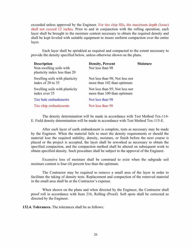
exceeded unless approved by the Engineer. For tire chip fills, the maximum depth (loose) shall not exceed 12 inches. Prior to and in conjunction with the rolling operation, each layer shall be brought to the moisture content necessary to obtain the required density and shall be kept leveled with suitable equipment to insure uniform compaction over the entire layer.
Each layer shall be sprinkled as required and compacted to the extent necessary to
provide the density specified below, unless otherwise shown on the plans.
Description Density, Percent Moisture Non-swelling soils with plasticity index less than 20
Not less than 98
Swelling soils with plasticity index of 20 to 35
Not less than 98; Not less nor more than 102 than optimum
Swelling soils with plasticity index over 35
Not less than 95; Not less nor more than 100 than optimum
Tire bale embankments Not less than 98
Tire chip embankments Not less than 98
The density determination will be made in accordance with Test Method Tex-114-
E. Field density determination will be made in accordance with Test Method Tex-115-E.
After each layer of earth embankment is complete, tests as necessary may be made by the Engineer. When the material fails to meet the density requirements or should the material lose the required stability, density, moisture, or finish before the next course is placed or the project is accepted, the layer shall be reworked as necessary to obtain the specified compaction, and the compaction method shall be altered on subsequent work to obtain specified density. Such procedure shall be subject to the approval of the Engineer.
Excessive loss of moisture shall be construed to exist when the subgrade soil
moisture content is four (4) percent less than the optimum.
The Contractor may be required to remove a small area of the layer in order to facilitate the taking of density tests. Replacement and compaction of the removed material in the small area shall be at the Contractor’s expense.
When shown on the plans and when directed by the Engineer, the Contractor shall
proof roll in accordance with Item 216, Rolling (Proof). Soft spots shall be corrected as directed by the Engineer.
132.4. Tolerances. The tolerances shall be as follows:

27
(1) Grade Tolerances.
(a) Stage Construction. Any deviation in excess of 0.1 foot in cross section and 0.1 foot in 16 feet measured longitudinally shall be corrected by loosening, adding, or removing the material, and reshaping and recompacting by sprinkling and rolling.
(b) Turnkey Construction. Any deviation in excess of 0.5 inch in cross section
and 0.5 inch in 16 feet measured longitudinally shall be corrected by loosening, adding or removing the material, reshaping and recompacting by sprinkling and rolling.
(2) Gradation Tolerances. The Engineer may accept the material, providing not
more than one out of the most recent five gradation tests performed are outside the specified limit on any individual sieve by more than 5percent.
(3) Density Tolerances. The Engineer may accept the work providing not more
than one out of the most recent five density tests performed is outside the specified density, provided the failing test is no more than 3.0 lb/ft3 outside the specified density.
(4) Plasticity Tolerances. The Engineer may accept the material providing not
more than one out of the most recent five plasticity index samples tested are outside the specified limit by no more than two points.
132.5. Measurement. This Item will be measured as follows:
(1) General. Retaining-wall-backfill areas which are also in embankment areas will be measured
for payment as embankment except as shown on the plans; such material shall meet the requirements for backfill material of the pertinent retaining-wall item(s). Limits of measurement for embankment in retaining-wall areas will be as shown on Standard Detail Sheet “Earthwork Measurement at Retaining Walls” (EMRW) in the plans.
Shrinkage or swellage factors will not be considered in determining the calculated
quantities.
(2) Class 1. Embankment will be measured in its original, natural position, and the volume computed in cubic yards by the average-end-area method.
(3) Class 2. Embankment will be measured by the cubic yard in vehicles as
delivered on the road.
(4) Class 3. Embankment will be measured by the cubic yard in its final position as the volume of embankment computed in place between (1) the original ground surfaces or the surface upon which the embankment is to be constructed, and (2) the lines, grades and slopes of the accepted embankment, using the average-end-area method.

28
(5) Class 4. Embankment will be measured by the each for the tire bales and by the cubic yard in vehicles as delivered on the road.
Class 3 is a plans-quantity measurement Item, and the quantity to be paid for will be
that quantity shown in the proposal and on the “Estimate and Quantity” sheet of the contract plans, except as may be modified by Article 9.8. If no adjustment of quantities is required, additional measurements or calculations will not be required.
132.6. Payment. The work performed and materials furnished in accordance with
this Item and measured as provided under “Measurement” will be paid for at the unit price bid for “Embankment” of the compaction method, type, and class specified. This price shall be full compensation for furnishing embankment and tires; for hauling; for placing, compacting, finishing, and reworking; and for all labor, royalty, tools, equipment, and incidentals necessary to complete the work.
When proof rolling is shown on the plans and directed by the Engineer, it will be
paid for in accordance with Item 216, “Rolling (Proof).”
When “Ordinary Compaction” is shown on the plans, all sprinkling and rolling, except proof rolling, will not be paid for directly, but will be considered subsidiary to this Item, unless otherwise shown on the plans.
When “Density Control” is shown on the plans, all sprinkling and rolling, except
proof rolling, will not be paid for directly, but will be considered subsidiary to this Item.
When subgrade is constructed under this project, correction of soft spots in the subgrade will be at the Contractor's expense. When subgrade is not constructed under this project, correction of soft spots in the subgrade will be in accordance with Article 4.3.
A.2 Recommended Modifications to Draft Specifications This section presents the recommended modifications based on this study. These
modifications are only to the following items of:
• Item 132.2: Material – Type E • Item 132.3 Construction Methods – (c) Tire Bale Embankments
Note: For clarity, colored text in the currently available TxDOT draft specifications was deleted. Instead, the green text in the following sections corresponds to suggested modifications to the current draft specification. Item 132.2: Embankment Material
. Type E. This material shall consist of tire bales made of whole, used passenger
vehicle tires or truck tires. Each bale shall contain only one type and size of tire, passenger

29
or truck. The bales shall be produced in a tire baler or equivalent as approved by the Engineer. The tire baler shall be capable of compressing whole tires to reach a dry unit weight not less than 30 pcf. Each bale shall use a minimum of 5 galvanized steel, stainless steel straps or wires. The bales shall not show sudden significant expansion upon cutting the straps or wires even after cutting the very last strap.
The size and weight of each tire bale shall be approved by the Engineer. To be
eligible to supply tire bales to a project, the tire baler or the tire supplier shall be registered to process waste tires by the Texas Commission on Environmental Quality (TCEQ).
The tire bales shall be of uniform size within each project such that they can be
easily stacked to facilitate rapid construction. The provider shall be able to supply tire bales with linear dimensions (width, length, height) not differing more than 0.5 ft from the specified dimensions.
The tire bales shall be load tested with the bale fully supported on a test floor
approved by the Engineer. During load testing, the bale shall be sandwiched between two steel plates. The top steel plate on which the load is applied shall be 1 inch thick and its size shall be identical to the loaded area of the bale. I-section steel shall be used to distribute the load uniformly over the steel plate, as approved by the Engineer. The load shall be applied using a hydraulic ram with a load capacity of at least 10,000 psf.
As part of the approval process of the bales supplied by a tire baler, direct shear
tests conducted on tire bales placed on a brick-like layout shall be conducted. The tests shall be conducted using a range of normal stresses representative of the tire bale projects to be authorized. In addition, a creep test and a compressive strength test, shall be conducted on the tire bales. The creep test shall be conducted over 72 hours under a sustained creep stress of 25 psi applied in both shear and compressive loading modes. The Engineer shall define the maximum allowable creep strain according to the characteristics of the project. For tire bales to be used in structures of up to 20 ft, the compressive strength test shall be conducted until the tire bale fails or until reaching an applied compressive stress of 25 psi, whichever is achieved first. A special study shall be conducted in projects involving structures with a height exceeding 20 ft. Additional tests that may be required by the Engineer include measurement of the rebound movement and lateral bulge of the tire bales and direct shear tests under different moisture conditions. In addition, the tire bales shall also have the following requirements:
The galvanized steel or stainless steel wires used as straps shall not break up to a
stress of 25 psi as applied on the tire bale surface, in the case of structures of up to 20 ft. Special studies may be required for higher structures. With regard to corrosion of these straps, requirements stipulated in Item 423.2 shall be met. Tire bale fills covered with geomembranes, which makes the tire fill impermeable to air and water, may not be subjected to the pH and resistivity requirements stipulated in Item 423.2.
30
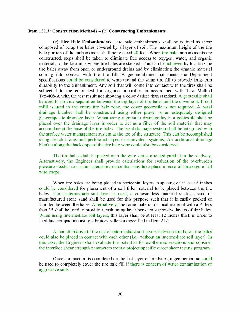
Item 132.3: Construction Methods – (2) Constructing Embankments
(c) Tire Bale Embankments. Tire bale embankments shall be defined as those composed of scrap tire bales covered by a layer of soil. The maximum height of the tire bale portion of the embankment shall not exceed 20 feet. When tire bale embankments are constructed, steps shall be taken to eliminate free access to oxygen, water, and organic materials to the locations where tire bales are stacked. This can be achieved by locating the tire bales away from open or underground drains and by eliminating the organic material coming into contact with the tire fill. A geomembrane that meets the Department specifications could be considered to wrap around the scrap tire fill to provide long-term durability to the embankment. Any soil that will come into contact with the tires shall be subjected to the color test for organic impurities in accordance with Test Method Tex-408-A with the test result not showing a color darker than standard. A geotextile shall be used to provide separation between the top layer of tire bales and the cover soil. If soil infill is used in the entire tire bale zone, the cover geotextile is not required. A basal drainage blanket shall be constructed using either gravel or an adequately designed geocomposite drainage layer. When using a granular drainage layer, a geotextile shall be placed over the drainage layer in order to act as a filter of the soil material that may accumulate at the base of the tire bales. The basal drainage system shall be integrated with the surface water management system at the toe of the structure. This can be accomplished using trench drains and perforated pipes or equivalent systems. An additional drainage blanket along the backslope of the tire bale zone could also be considered.
The tire bales shall be placed with the wire straps oriented parallel to the roadway.
Alternatively, the Engineer shall provide calculations for evaluation of the overburden pressure needed to sustain lateral pressures that may take place in case of breakage of all wire straps.
When tire bales are being placed in horizontal layers, a spacing of at least 6 inches
could be considered for placement of a soil filler material to be placed between the tire bales. If an intermediate soil layer is used, a cohesionless material such as sand or manufactured stone sand shall be used for this purpose such that it is easily packed or vibrated between the bales. Alternatively, the same material or local material with a PI less than 35 shall be used to provide a cushioning layer between successive layers of tire bales. When using intermediate soil layers, this layer shall be at least 12 inches thick in order to facilitate compaction using vibratory rollers as specified in Item 217.
As an alternative to the use of intermediate soil layers between tire bales, the bales
could also be placed in contact with each other (i.e., without an intermediate soil layer). In this case, the Engineer shall evaluate the potential for exothermic reactions and consider the interface shear strength parameters from a project-specific direct shear testing program.
Once compaction is completed on the last layer of tire bales, a geomembrane could
be used to completely cover the tire bale fill if there is concern of water contamination or aggressive soils.

31
A.3 Additional Considerations
Based on the information provided by Zornberg et al. (2005), additional aspects not covered within the scope of this implementation study could be considered for future refinement of the draft specifications. These include:
• Reference documents, including terminology, and laboratory test
procedures. • The responsibilities of the parties involved with the fabrication, storage,
transport, and installation of a tire bale embankment system. • Permitting requirements through federal, state, and local agencies for waste
tire storage, transport, including pre-processing, cleaning, storing, etc. • Equipment and procedures for fabricating tire bales, including confinement
devices. • Physical, material, and chemical properties and requirements for
manufacturing quality control (MQC) testing, possibly including third-party testing and certifications to verify the tire bales have the requisite properties before they are transported to storage or to a construction site.
• Product storage and transportation with fire protection and fire suppression requirements, which must comply with the local Fire Marshall regulations.
• Site preparation, including placement of ancillary foundation materials. • Handling and placement of tire bales, ancillary materials, and any
connection devices. • Requirements for handling and installing facing materials. • Field quality control monitoring and testing tire bales and ancillary
materials. • Performance monitoring, both short-term (from placement to the end of
construction) and in-service monitoring. Appropriate instrumentation to monitor and measure settlement, lateral movement, temperature, and water head may be required at some sites to verify the tire bale embankment is performing as anticipated during design.