1 qos control schemes for two-stage ethernet passive optical access networks speaker : hsuan-ming...
Post on 22-Dec-2015
216 views
TRANSCRIPT

1
QoS Control Schemes for Two-Stage Ethernet Passive Optical Access Networks
Speaker : Hsuan-Ming ChenAdvisor : Ho-Ting WuDate : 2005.10.18

2
Outline
• Introduction• Overview and Proposed Architecture• Proposed Architecture• Dynamic Bandwidth Allocation with QoS Supp
ort for IP-EPONS• Multipoint Control Protocol (MPCP)• Inter-ONU DBA scheme• Sub-OLT Scheduling
• Performance Evaluation• Conclusion
3
Introduction
• An EPON (Ethernet passive optical networks)• a point-to-multipoint (1:N)optical access
network with no active elements in the signal path
• The network provides two-way operation• GATE• REPORT

4
Introduction (cont.)
• EPON network architecture

5
Overview and Proposed Architecture
• Time-sharing protocols represent the best method of optical channel sharing in optical access networks • (i.e. time division multiple access, TDMA)• can either be static (simple) or dynamic• Dynamic bandwidth allocation based
upon a time interleaving method• (i.e., the interleaved polling scheme with
an adaptive cycle time (IPACT) scheme)

6
Proposed Architecture
• Present a cascaded two-stage EPON architecture• Adds another intermediate level of ONU
nodes to the network, termed sub-OLT• Refer to this architecture as penetrated-
EPON (P-EPON)

7
Proposed Architecture (cont.)

8
Proposed Architecture (cont.)
Illustration of sub-OLT functionalities
9
Proposed Architecture (cont.)
• Major motivations for deploying a two-stage P-EPON architecture• Allow more end-users (ONU nodes) to share
the uplink OLT bandwidth, without incurring extra overhead for switch-over between users
• Enable longer access reach/distances, since the use of intermediate sub-OLT nodes effectively adds another level of electrical regeneration
• Reduce OLT hardware complexity significantly

10
Multipoint Control Protocol (MPCP)
• EPON standard, the multipoint control protocol (MPCP)• 0. OLT sends a GATE message to each ONU through
the downstream connection• 1. Gate message contains time when the ONU should
start transmission and the length of its transmission window
• 2. Upon receiving its GATE message, the ONU performs synchronization and updates its local parameters
• 3. When its local clock matches the transmission start time sent by the OLT
• 4. The ONU starts sending information packets to the OLT

11
Multipoint Control Protocol (MPCP)
• 5. At the end of its transmission window, the ONU sends a REPORT message to the OLT to report its current buffer occupancy and request bandwidth for the next transmission cycle
• 6. Upon receiving REPORT message from the ONU, the OLT updates its report table and passes the message to the DBA module responsible for bandwidth allocation decision
• 7. At the end of the transmission cycle and upon receiving REPORT messages from all ONUs in the network, the DBA module in the OLT calculates the new window size for every ONU in the network
• 8. a series of GATE messages are generated and broadcast continuously to the ONUs by the OLT to initiate the next transmission cycle

12
Transmission Cycle Time
• Denote transmission cycle time by TTCT, which is the sum of all ONUs’ transmission time• If TTCT is too large
• the average packet queueing delay inside ONU nodes might increase randomly
• If TTCT is restricted too much• the average packet delay might still increase unnecessarily, bec
ause more bandwidth is wasted on frequent MPCP messaging and inter-ONU guard times
• Static bandwidth allocation algorithms that each ONU is granted a fixed transmission timeslot per transmission cycle. Namely, the ONU timeslot can be calculated as:

13
Inter-ONU DBA scheme
• ti = (TTCT – N x tg) x wi with
• Where ti is the timeslot allocated to ONU i• wi is the weight of ONU I according to its ser
vice level agreement (SLA)• N is the number of ONU nodes

14
Inter-ONU DBA scheme (cont.)
• However, assigning static capacity to ONU nodes will preclude idle capacity reuse and yields generally lower utilizations for bursty traffic
• To mitigate the above concerns, the others proposed an inter-ONU DBA scheme in which ONU nodes are portioned into two groups• Underloaded
• requesting bandwidth below their minimum guarantee defined by the maximum transmission
• Overloaded

15
Inter-ONU DBA scheme (cont.)
• This algorithm can be described as follows:

16
Inter-ONU DBA scheme (cont.)
• ri is the requested transmission time of ONU node i
• is the total excess transmission time saved from underloaded ONU nodes
• is the corresponding share of the total excess transmission time allocated to overloaded ONU node
• K and M are the set of overloaded and underloaded ONU nodes, respectively

17
Inter-ONU DBA scheme (cont.)
• The above algorithm may still yield some wasted (unused) bandwidth capacityThe total excess transmission time might n
ot always fully occupied by the overloaded ONU nodes

18
Inter-ONU DBA scheme (cont.)
• modify this algorithm with a more advanced dynamic cycle time upper bounded at TMAX-TCT as follows:
• Where denotes the total extra transmission time requested by overloaded ONU nodes
19
Sub-OLT Scheduling
• The first option for these algorithms may be to apply the above modified DBA scheme into both sections as EPON dynamic scheduling algorithm 1 (E-DSA1)

20
Sub-OLT Scheduling (cont.)
• The future incoming traffic of sub-OLT nodes is predictable
• The fact permits a sub-OLT to prerequest some bandwidth in its REPORT message for absent packets that will arrive before the next transmission of this sub-OLT
• This scheme can exempt some packets that were not reported to the OLT by the sub-OLT in E-DSA1 from waiting at least one cycle time before being transmitted (unlike E-DSA1)

21
Sub-OLT Scheduling (cont.)
• In order to implement this algorithm, each sub-OLT must estimate its future incoming traffic from the attached ONUs within some reference time based upon the information in its grant table
• This estimate must be added to the bandwidth request in the REPORT message of the sub-OLT

22
Sub-OLT Scheduling (cont.)

23
Sub-OLT Scheduling (cont.)
• If level-1 and level-2 sections run at different link capacities
• can be simply converted as follows:
• where C1 and C2 are the link capacities of the level-1 and level-2 sections
• m and n are the first and last ONU nodes that will transmit in the reference time window

24
Sub-OLT Scheduling (cont.)
• we refer to this improved algorithm that takes into consideration both imminent and predicted bandwidth requests as EPON dynamic scheduling algorithm 2 (E-DSA2)
25
Priority Queueing
• expedited forwarding (EF) class provides the highest priority for strict delay sensitive services such as voice
• assured forwarding (AF) class provides a lower, i.e., medium, priority level for services of nondelay sensitive nature, but still requiring guaranteed bandwidth such as video applications
• best effort (BE) class provides the lowest priority for delay tolerable services such as web browsing, e-mail, and file transfer
26
Priority Queueing (cont.)
• A two-stage queueing-based priority scheduler• It’s can prevent higher priority queues fro
m unreasonably monopolizing the granted transmission window

27
Priority Queueing (cont.)
• (a) Intra-ONU scheduling (E-DSA1)

28
Priority Queueing (cont.)
•(b) Intrasub-OLT scheduling (E-DSA1)

29
Priority Queueing (cont.)
(c) Intrasub-OLT scheduling (E-DSA2)

30
Performance Evaluation
• Network Model• P-EPON with one OLT• 8 sub-OLT nodes• 32 ONU nodes
• Traffic is distributed as follows :• 20% from the local users of the sub-OLT node
s • 80% from the end users of ONU nodes
31
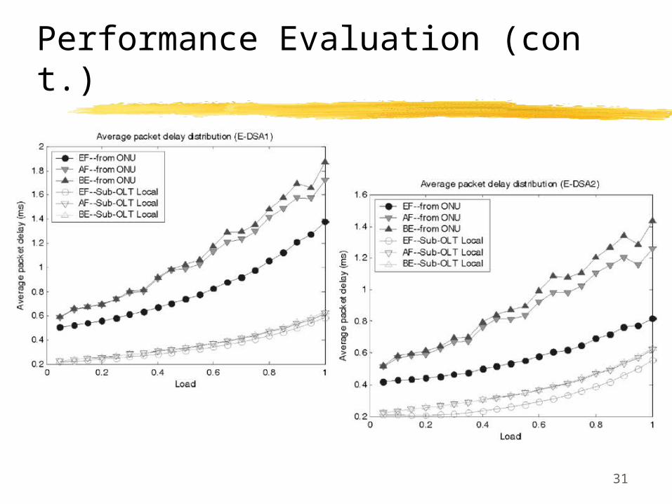
Performance Evaluation (cont.)

32
Performance Evaluation (cont.)
(a) ONU’s average packet delay (b) Sub-OLT average packet delay (access distance 20 km)
33
Conclusion
• Proposed a novel two-stage enhancement, penetrated-EPON (P-EPON)
• This scheme utilizes an intermediate state to help increase universality and boost distance and coverage within the access domains

34
References
• Shami, A.; Bai, X.; Ghani, N.; Assi, C.M.; Mouftah, H.T., “QoS Control Schemes for Two-Stage Ethernet Passive Optical Access Networks”, IEEE Journal on Selected Areas in Communications, Vol. 23, No. 8, pp. 1467- 1478, Aug 2005
• C. Assi, Y. Ye, S. Dixit, and M. A. Ali, “Dynamic bandwidth allocation for quality-of-service over Ethernet PONs,” IEEE J. Sel. Areas Commun., vol. 21, no. 9, pp. 1467–1477, Nov. 2003

35
Pseudocode for E-DSA-1 DBA scheduler

36
Pseudocode for E-DSA-2 DBA scheduler