1 pupil detection and tracking system lior zimet sean kao ee 249 project mentors: dr. arnon amir...
Post on 21-Dec-2015
213 views
TRANSCRIPT
1
Pupil Detection and
Tracking System
Lior Zimet
Sean Kao
EE 249 Project
Mentors: Dr. Arnon Amir
Yoshi Watanabe
December 5, 2002 EE 249 Project Presentation Lior Zimet and Sean Kao
2
Outline
Introduction and Goals Design Methodology Model of Computation Mapping and Implementation Verification Conclusions

December 5, 2002 EE 249 Project Presentation Lior Zimet and Sean Kao
3
Motivation Human-computer interfaces are becoming
more important New interfaces may benefit from knowledge
of the location of the user’s eyes– Auto-stereoscopic displays– Virtual Reality interfaces– Facial recognition systems– Eye gaze tracking

December 5, 2002 EE 249 Project Presentation Lior Zimet and Sean Kao
4
Goals Exercise design process from functional
specification to implementation and verification
Develop an embedded system that will find the two-dimensional location of a user’s pupils
Apply various methodologies we have learned Use a heterogeneous collection of various
components in a real-time environment

December 5, 2002 EE 249 Project Presentation Lior Zimet and Sean Kao
5
Background Human pupils may be found using two
infrared light sources An on-axis light source will give the “red-
eye” effect.
December 5, 2002 EE 249 Project Presentation Lior Zimet and Sean Kao
6
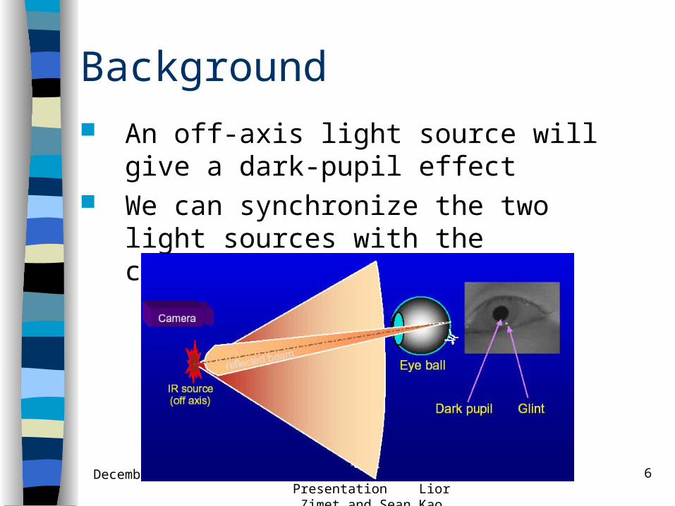
Background An off-axis light source will give a dark-
pupil effect We can synchronize the two light
sources with the capturing device
December 5, 2002 EE 249 Project Presentation Lior Zimet and Sean Kao
7
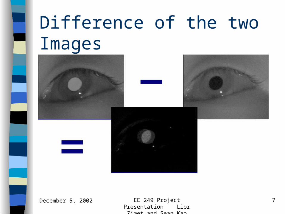
Difference of the two Images

December 5, 2002 EE 249 Project Presentation Lior Zimet and Sean Kao
8
Design Methodology Begin with a definition of the system with
illustrations Make a formal specification using the Unified
Modeling Language Describe the system using a behavioral model Explore architectural space Map functionality into chosen architecture Verify implementation

December 5, 2002 EE 249 Project Presentation Lior Zimet and Sean Kao
9
System Definition
Take in an image illuminated with two different light sources
Find the pupils in the image Calculate the position of the pupils Output the coordinates
Sensor&Lightcontrol
Videostream
handling
Image Processing
PupilDetection
Sensor Tracking OutputInterface
UserInterface
2DLocation

December 5, 2002 EE 249 Project Presentation Lior Zimet and Sean Kao
10
UML Diagrams
UML is used for formally describing a system
Use-case diagram shows functions of the system without implying how it is done
Class diagram shows what functional blocks are used
Sequence diagrams show how the use-cases are executed

December 5, 2002 EE 249 Project Presentation Lior Zimet and Sean Kao
11
Use Case Diagram
Image Target
User
Receiver
Illuminate Target
*
*
Capture Image
*
*
«extends»
SynchronizeIllumination with Image Capture
Activate System
**
Modify Settings
*
*
Calculate PupilPosition
«uses»
«uses»
«uses»
«extends»
Format Data
* *
«extends»
System
«invariant»{On-axis and off-axis LEDs may not be lit at the same time.}
Use Case: 1. User activates the system.2. User may modify system characteristics.3. System synchronizes illumination with image capturing.4. System calculates pupil position based on caputed images.5. System outputs position based on output format.

December 5, 2002 EE 249 Project Presentation Lior Zimet and Sean Kao
12
Class Diagram
+Activate()+Deactivate()
-Location : bool = {on-axis,off-axis}
«implementation class»IR Light Source
+Activat_OnAxis_Light()+Activat_OffAxis_Light()
-FrameType : bool = {Odd,Even}
«implementation class»Synchronizer
-Get_Image()-Send_Pixel_Data()-Send_Next_Frame_Signal()-Send_Next_Line_Signa()-Send_Next_Pixel_Signal()+Initialize()
-Brightness : int-Resolution : int
«implementation class»Sensor
-Store_Pixel()-Advance_Line()-Advance_Frame()-Get_Pixel()
-Current_Location : long
«implementation class»Memory Handler
+LocationX : int+LocationY : int-Value : byte
«struct»Pixel
+Size : long
«struct»Frame
+Size : int
«struct»Line
+Send_Tick()
-Frequency
«implementation class»System Clock
-Subtract2Lines()-Threshold_Line()-Connect_Components()-Track_Components()-Store_Pupil_Locations()+Send_Pupil_Locations()
«implementation class»Image Processor
-LocationX : int-LocationY : int
«struct»Pupil Locations
+Display_Locations()
«implementation class»Display
+Initialize()
«implementation class»Controller
2..* 1
11 1
1
1
1
11
11
1
1 2
1
1 n
1n
3
1
n1
1
1
1
1

December 5, 2002 EE 249 Project Presentation Lior Zimet and Sean Kao
13
Y-Chart of the Project
SystemBehavior
SystemArchitecture
Mapping
Refine
Implementationof System
First, we’ll describe the system behavior with an appropriate model of computation

December 5, 2002 EE 249 Project Presentation Lior Zimet and Sean Kao
14
Model of Computation
Processes large amounts of data in a similar way
Dataflow model is the most appropriate Our system is not control-centric But some parts of the system are easier
to describe using sequential algorithms Mixed models of computation

December 5, 2002 EE 249 Project Presentation Lior Zimet and Sean Kao
15
Simulink versus Ptolemy (Virgil) Ptolemy has the ability to mix models of
computation and has support for synchronous dataflow
But Virgil does not have a simple way to integrate sequential algorithms
Simulink has extensive support for sequential algorithms (Matlab)
But lacks clearly defined semantics, combination of dataflow and discrete-event

December 5, 2002 EE 249 Project Presentation Lior Zimet and Sean Kao
16
Simulink Model of Computation Use one clock to synchronize the system No implicit definitions how many tokens are generated or
used We use counters and synchronous signals to determine how
many “tokens” are on edges
December 5, 2002 EE 249 Project Presentation Lior Zimet and Sean Kao
17
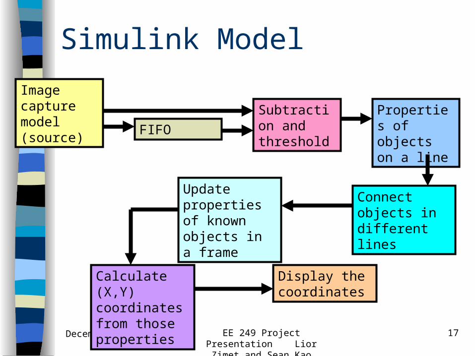
Simulink Model
Properties of objects on a line
Connect objects in different lines
Update properties of known objects in a frame
Calculate (X,Y) coordinates from those properties
Display the coordinates
Image capture model (source)
FIFO
Subtraction and threshold
December 5, 2002 EE 249 Project Presentation Lior Zimet and Sean Kao
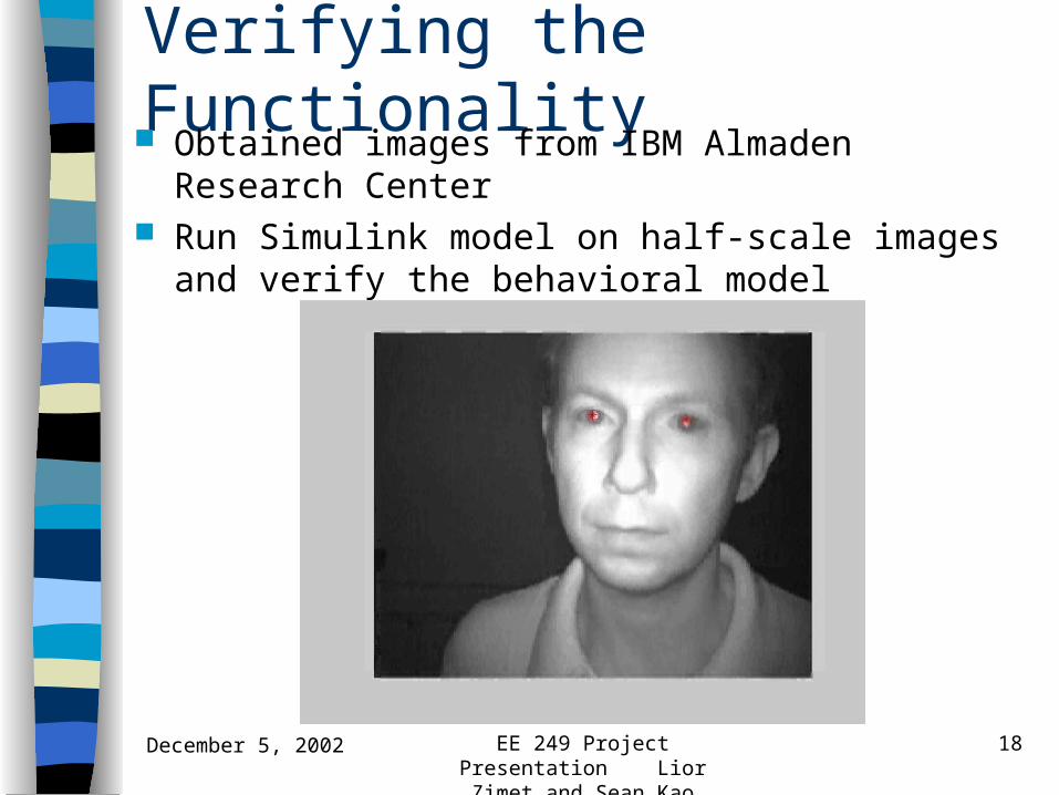
18
Verifying the Functionality Obtained images from IBM Almaden Research
Center Run Simulink model on half-scale images and verify
the behavioral model

December 5, 2002 EE 249 Project Presentation Lior Zimet and Sean Kao
19
System Architecture on Y-Chart
SystemBehavior
SystemArchitecture
Mapping
Refine
Implementationof System
Next, we’ll define the system architecture

December 5, 2002 EE 249 Project Presentation Lior Zimet and Sean Kao
20
System Architecture Image capture device Programmable hardware Frame buffer FIFO Interface controller PC Architecture Space
Programmable hardware
PCImage capture device
Frame buffer FIFO
Interface controller

December 5, 2002 EE 249 Project Presentation Lior Zimet and Sean Kao
21
Mapping on Y-Chart
SystemBehavior
SystemArchitecture
Mapping
Refine
Implementationof System
Map the behavior onto the architecture

December 5, 2002 EE 249 Project Presentation Lior Zimet and Sean Kao
22
Mapping and HW/SW Partition Frame buffer
– RAM vs FIFO Subtraction and thresholding of data
– Hardware offers a fast, simple way – Software requires high memory bandwidth
Extracting objects from the video data– Algorithm is non-trivial to implement in hardware, a
fully parallel implementation is costly– Software implementation is straightforward for
sequential algorithms, but requires fast data transfers to processor

December 5, 2002 EE 249 Project Presentation Lior Zimet and Sean Kao
23
Mapping and HW/SW Partition Calculating coordinates
– Requires a hardware divider (expensive)– Needs lots of data to be passed, calculation is
cheap in software Displaying the XY coordinates
– Hardware requires complicated interface to some type of display
– Easy to display on monitor, only requires small amounts of data to transfer
December 5, 2002 EE 249 Project Presentation Lior Zimet and Sean Kao
24
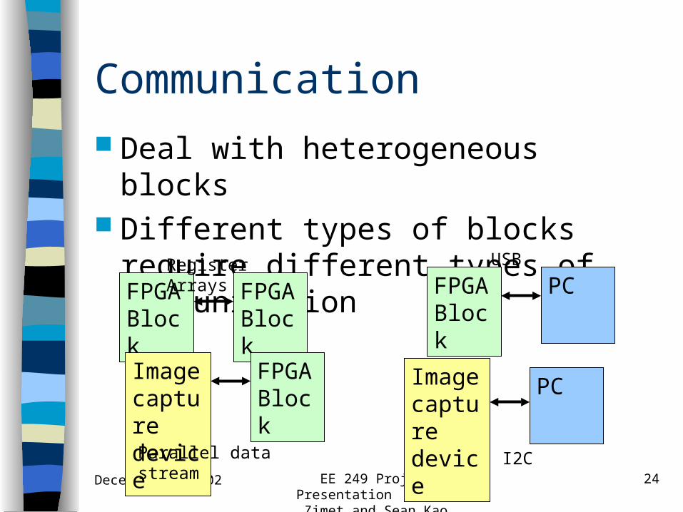
Communication
Deal with heterogeneous blocks Different types of blocks require
different types of communication
FPGABlock
FPGABlock
Image capture device
FPGABlock
FPGABlock
PC
Image capture device
PC
Register Arrays
Parallel data stream
USB
I2C
December 5, 2002 EE 249 Project Presentation Lior Zimet and Sean Kao
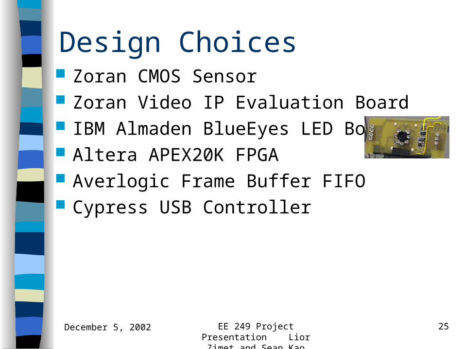
25
Design Choices Zoran CMOS Sensor Zoran Video IP Evaluation Board IBM Almaden BlueEyes LED Board Altera APEX20K FPGA Averlogic Frame Buffer FIFO Cypress USB Controller

December 5, 2002 EE 249 Project Presentation Lior Zimet and Sean Kao
26
Design ChoicesProperties of objects on a line
Connect objects in different lines
Update properties of known objects in a frame
Calculate (X,Y) coordinates from those properties
Display the coordinates
Image capture model (source) FIFO
Subtraction and threshold
CMOS Sensor
Frame buffer
Altera FPGA and Zoran Evaluation board
PC
USB controller

December 5, 2002 EE 249 Project Presentation Lior Zimet and Sean Kao
27
Implementation from Behavioral Model
No available tool that can effectively apply model of computation to various architectural implementations yet
Xilinx SysGen tool cannot handle data stream Real-Time Workshop for Simulink
– Does not necessarily generate efficient code Various programs that generate Verilog from
C– May not be synthesizable

December 5, 2002 EE 249 Project Presentation Lior Zimet and Sean Kao
28LeonardoSpectrum and Quartus
ModelSim
Simulink
Implementation Verilog (synthesized manually) is used for hardware
blocks C/C++ (synthesized manually) used for software
blocks
SystemBehavior
SystemArchitecture
Mapping
Refine
Implementationof System

December 5, 2002 EE 249 Project Presentation Lior Zimet and Sean Kao
29
Verification
ModelSim used to simulate Verilog LeonardoSpectrum used to synthesize
Verilog into FPGA netlist Quartus used to map and place & route Visual C++ used to compile and
simulate software components
December 5, 2002 EE 249 Project Presentation Lior Zimet and Sean Kao
30
System Demo

December 5, 2002 EE 249 Project Presentation Lior Zimet and Sean Kao
31
Conclusions Good design methodology allowed us to exercise
the complete design process in a short time span (time-to-market)
Separating functionality from implementation can solve many errors early in the design process
Communication and interface-based design is vital for system integration
No available programs to automatically synthesize the process all the way down
Tried to apply EE 249 design methodologies, but implemented with traditional techniques
December 5, 2002 EE 249 Project Presentation Lior Zimet and Sean Kao
32
Acknowledgements
Dr. Arnon Amir (IBM Almaden Research Center)
Zoran Video IP team Zoran CMOS Sensor team Yoshi Watanabe Prof. Sangiovanni-Vincentelli Rong Chen