1 petroleum engineering 406 lesson 13 shallow water flows
TRANSCRIPT
1
Petroleum Engineering 406
Lesson 13 Shallow Water Flows
2
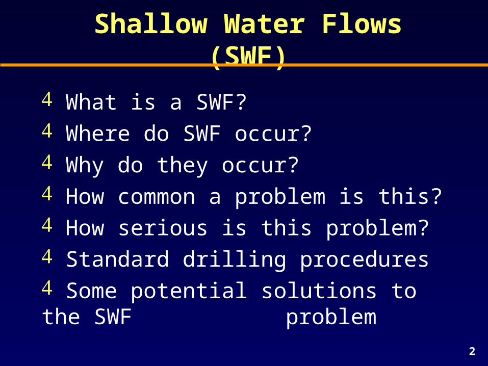
Shallow Water Flows (SWF)
What is a SWF? Where do SWF occur? Why do they occur? How common a problem is this? How serious is this problem? Standard drilling procedures Some potential solutions to the SWF
problem
3
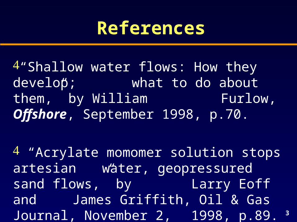
References
“Shallow water flows: How they develop; what to do about them,” by William Furlow, Offshore, September 1998, p.70.
“Acrylate momomer solution stops artesian water, geopressured sand flows,” by Larry Eoff and James Griffith, Oil & Gas Journal, November 2, 1998, p.89.
4
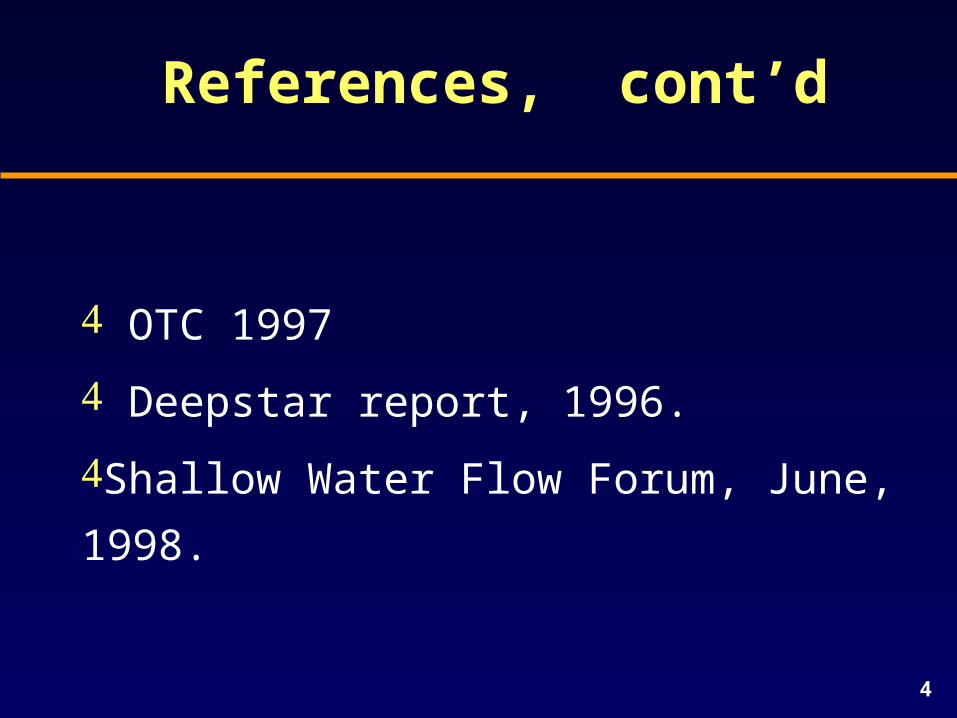
References, cont’d
OTC 1997
Deepstar report, 1996.
Shallow Water Flow Forum, June, 1998.
5
What are Shallow Water Flows (SWF)?
Shallow water flows are flows from
overpressured sands encountered at
shallow depth below the mud line in
deepwater regions of the world.
6
What is a Shallow Water Flow?
Sometimes sand flows with the water. Flow rates as high as 25,000 bbls/day have been reported (~730 gal/min).
A video presentation at the “Shallow Water Flow” Forum (June, 1998) showed a SWF producing plumes of sand and debris that boiled up 60 ft from the seafloor.
7
Where do SWF Occur?
SWF typically occur in water depths beyond 1,500 ft, at depths ranging from 300 to 3,500 ft below the mud line.
SWF represent a recently encountered phenomenon in the Gulf of Mexico, West of the Shetlands, the Norwegian Sea, Southern Caspian Sea, and the North Sea.
8
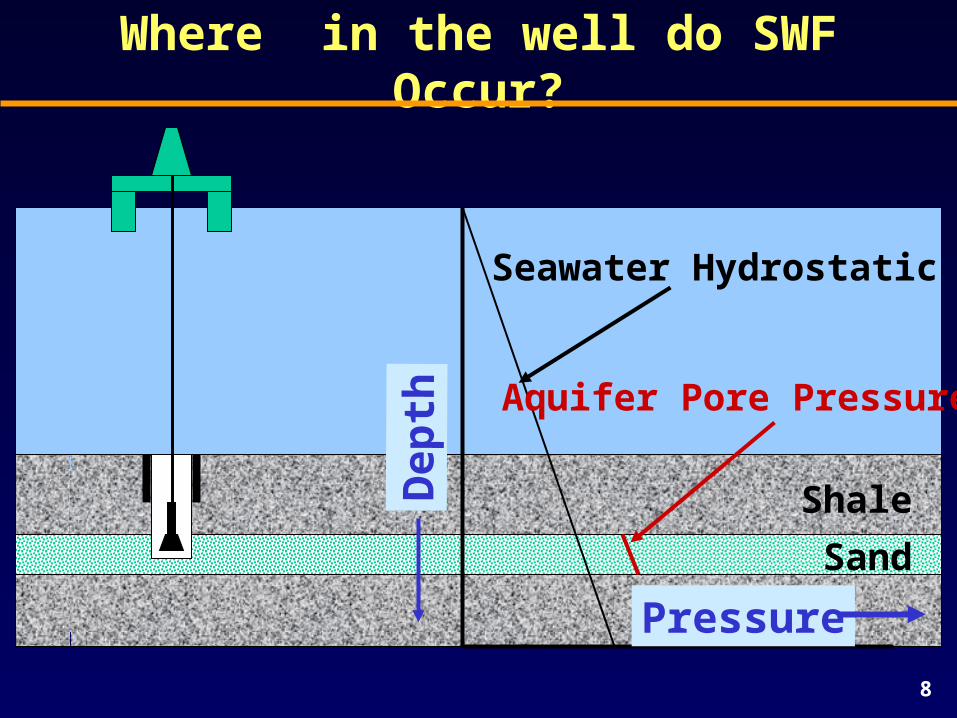
Where in the well do SWF Occur?
Pressure
Dep
th
Seawater Hydrostatic
Shale
Sand
Aquifer Pore Pressure
9
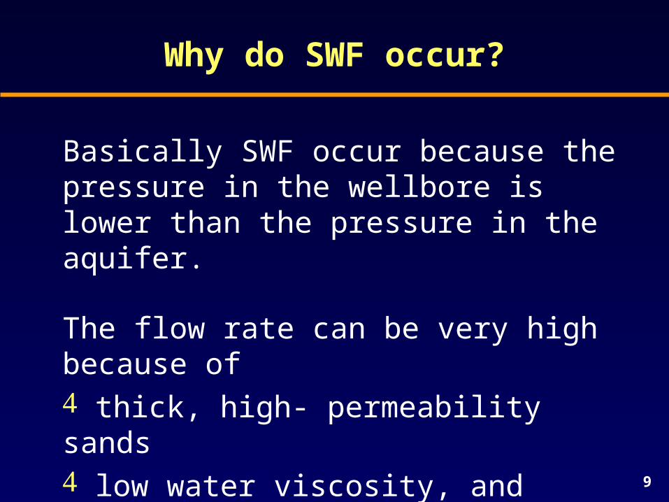
Why do SWF occur?
Basically SWF occur because the pressure in the wellbore is lower than the pressure in the aquifer.
The flow rate can be very high because of thick, high- permeability sands low water viscosity, and
sufficient pressure differential.
10
How common a problem is this?
It has been suggested that 30 to 40% of all deepwater wells in the Gulf of Mexico encounter this problem.
Once the flow begins it is very difficult to stop. This makes it difficult, and sometimes impossible, to get a good cement job around the casing.
11
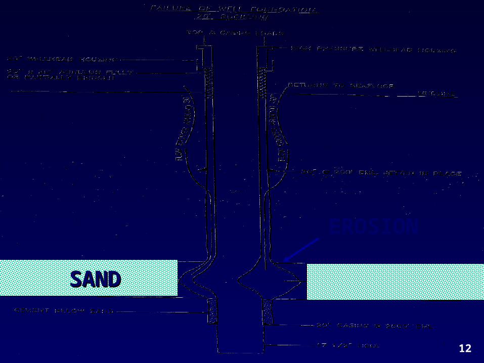
How serious is this problem?
Hole erosion and poor cement jobs can result in settling of the casing strings, accompanied by buckling of inner casing strings, leading to serious damage or loss of well ($10-20 million?).
At Ursa a number of wells were washed out, and had to be relocated. Total cost is estimated to be around $150 million!
12
EROSION
SANDSAND
13
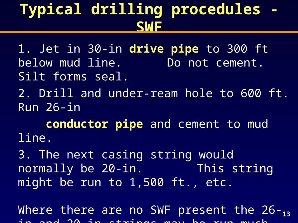
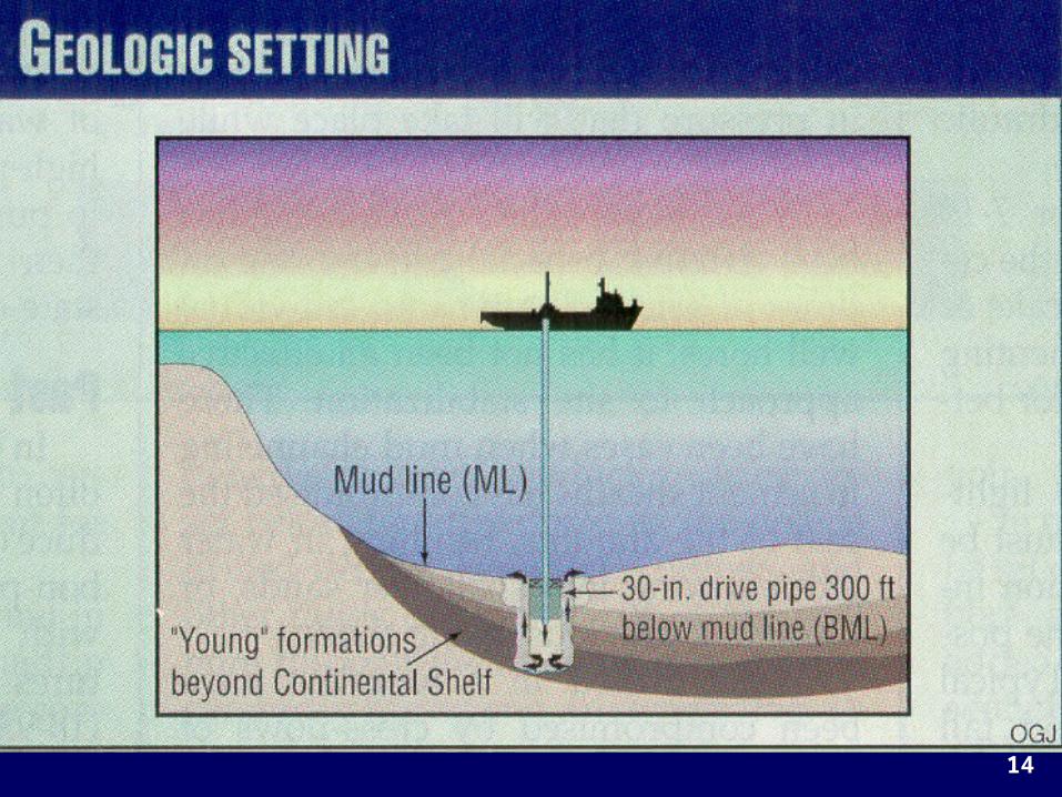
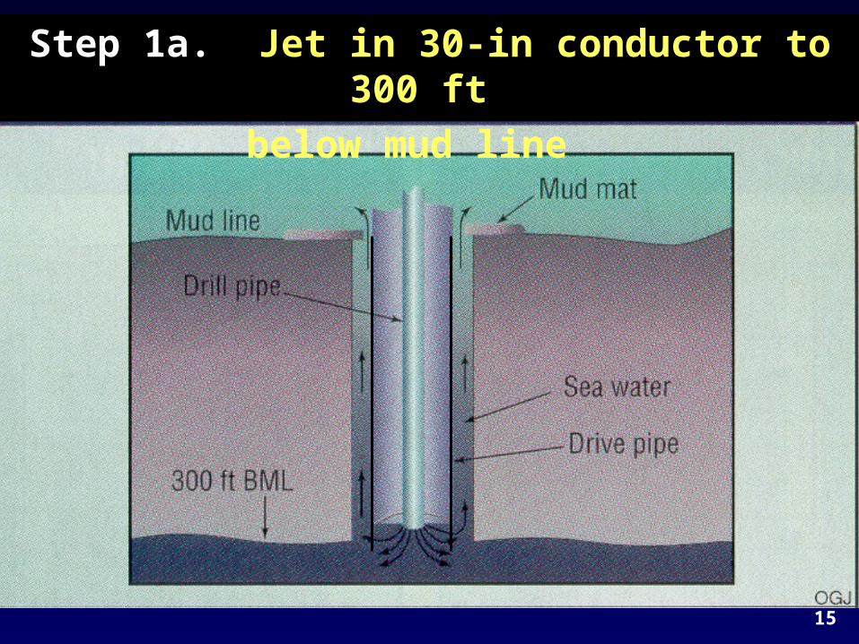
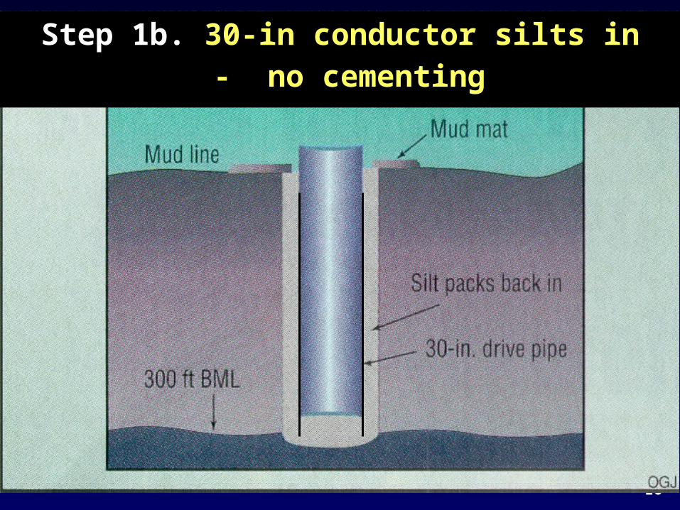
Typical drilling procedules - SWF
1. Jet in 30-in drive pipe to 300 ft below mud line. Do not cement. Silt forms seal.
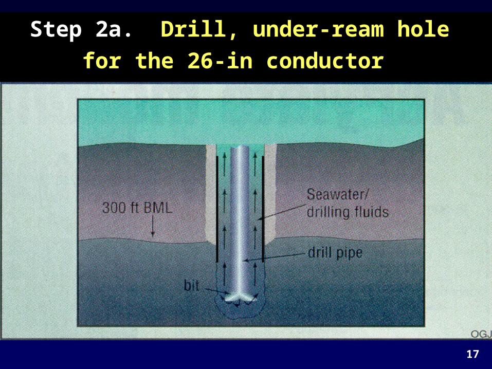
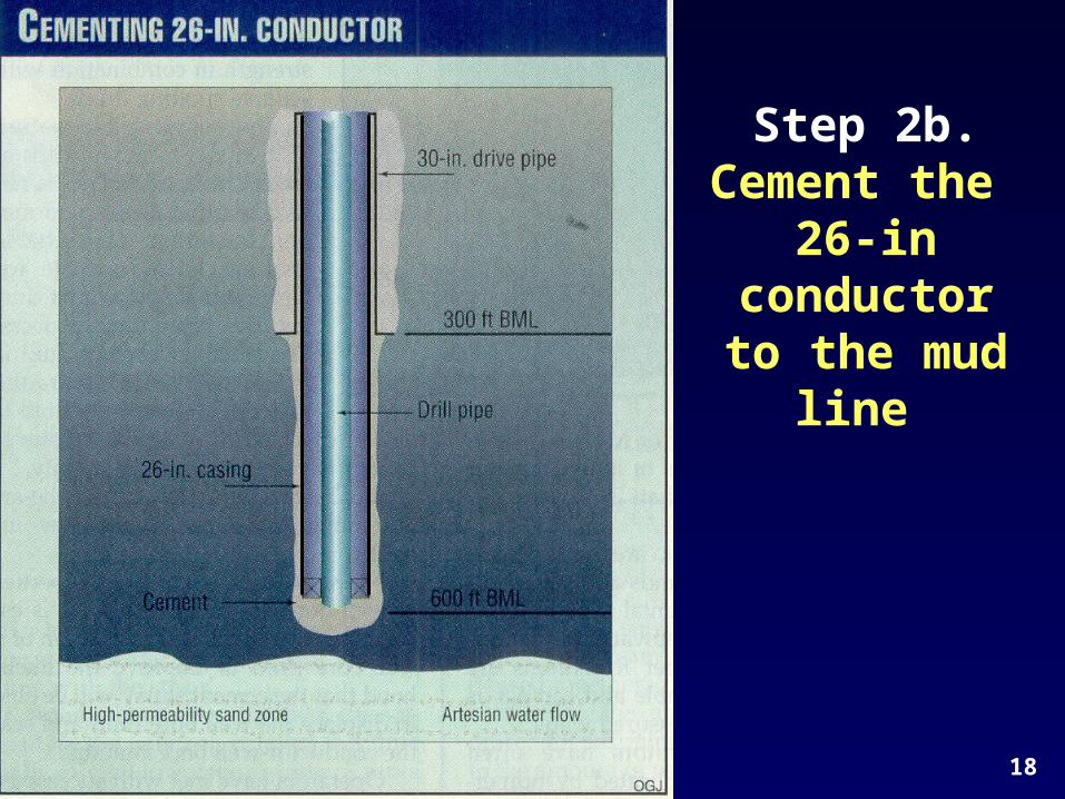
2. Drill and under-ream hole to 600 ft. Run 26-in
conductor pipe and cement to mud line.
3. The next casing string would normally be 20-in. This string might be run to 1,500 ft., etc.
Where there are no SWF present the 26-in and 20-in strings may be run much deeper. Some string sizes may be eliminated.
14
15
Step 1a. Jet in 30-in conductor to 300 ft
below mud line
16
Step 1b. 30-in conductor silts in - no cementing
17
Step 2a. Drill, under-ream hole
for the 26-in conductor
18
Step 2b. Cement the
26-in conductor to the mud line
19
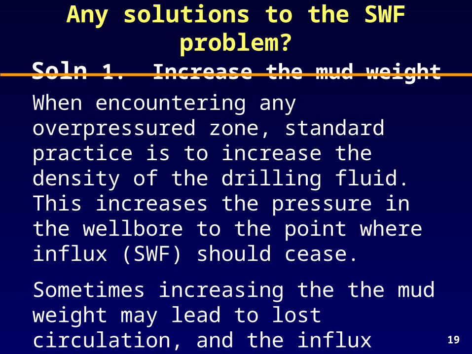
Any solutions to the SWF problem?Soln 1. Increase the mud weight
When encountering any overpressured zone, standard practice is to increase the density of the drilling fluid. This increases the pressure in the wellbore to the point where influx (SWF) should cease.
Sometimes increasing the the mud weight may lead to lost circulation, and the influx continues, possibly turning into an underground blowout.
20
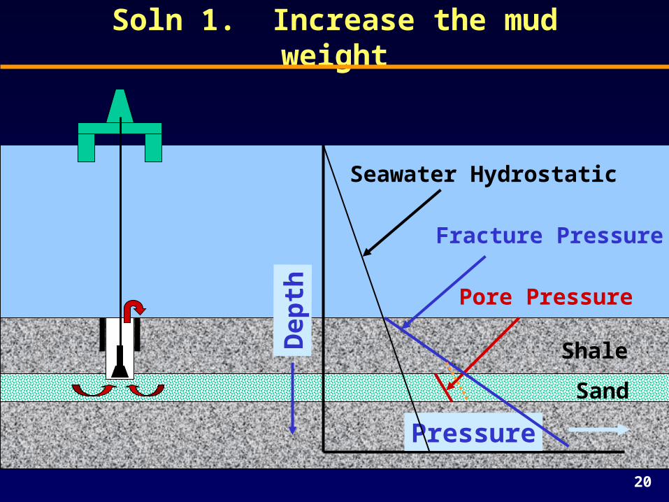
Soln 1. Increase the mud weight
Pressure
Dep
th
Seawater Hydrostatic
Shale
Sand
Pore Pressure
Fracture Pressure
21
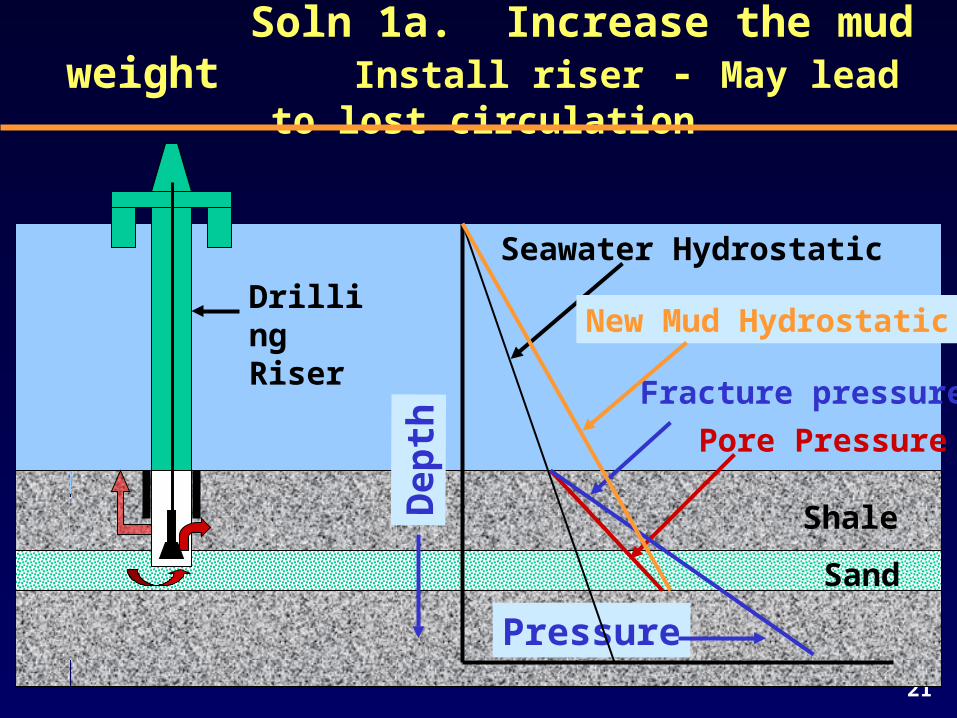
Soln 1a. Increase the mud weightInstall riser - May lead to lost circulation
Pressure
Dep
th
Seawater Hydrostatic
Shale
Sand
Pore Pressure
Fracture pressure
New Mud HydrostaticDrilling Riser
22
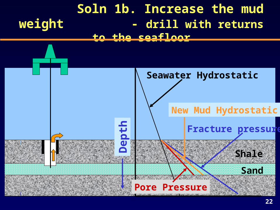
Soln 1b. Increase the mud weight- drill with returns to the seafloor
Dep
th
Seawater Hydrostatic
Shale
Sand
Pore Pressure
Fracture pressure
New Mud Hydrostatic
23
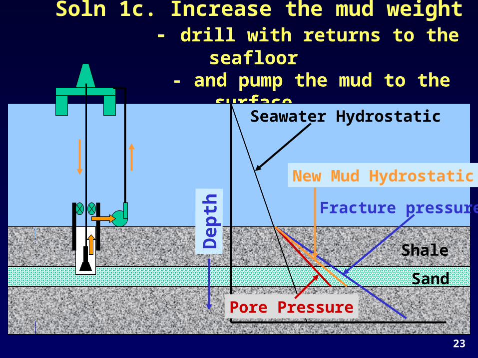
Soln 1c. Increase the mud weight- drill with returns to the seafloor
- and pump the mud to the surface…
Dep
th
Seawater Hydrostatic
Shale
Sand
Pore Pressure
Fracture pressure
New Mud Hydrostatic
24
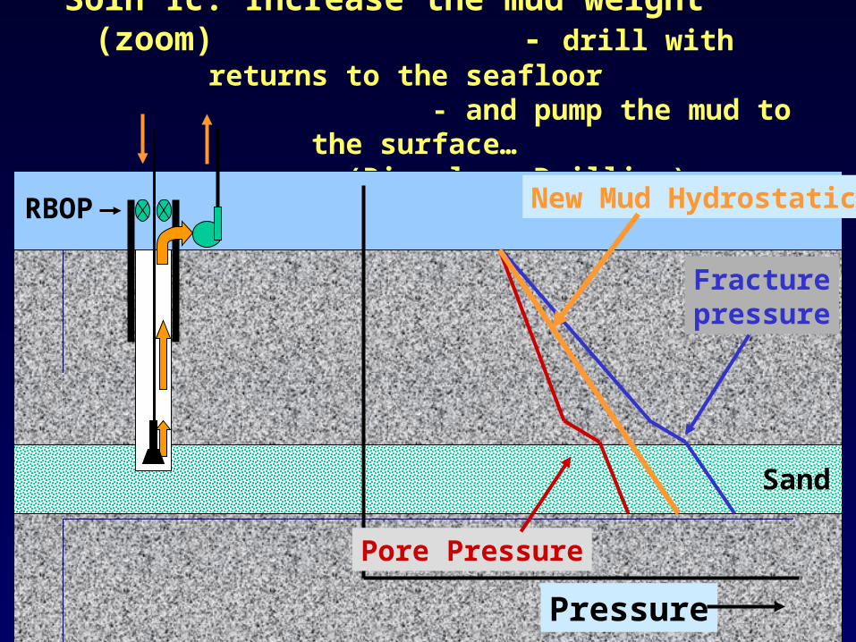
Soln 1c. Increase the mud weight (zoom) - drill with returns to the seafloor
- and pump the mud to the surface… (Riserless Drilling)
Pressure
Sand
Pore Pressure
Fracturepressure
New Mud HydrostaticRBOP
25
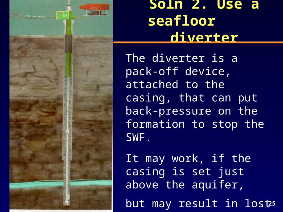
Soln 2. Use a seafloor diverter
The diverter is a pack-off device, attached to the casing, that can put back-pressure on the formation to stop the SWF.
It may work, if the casing is set just above the aquifer,
but may result in lost circulation, and possibly broaching to the surface.
26
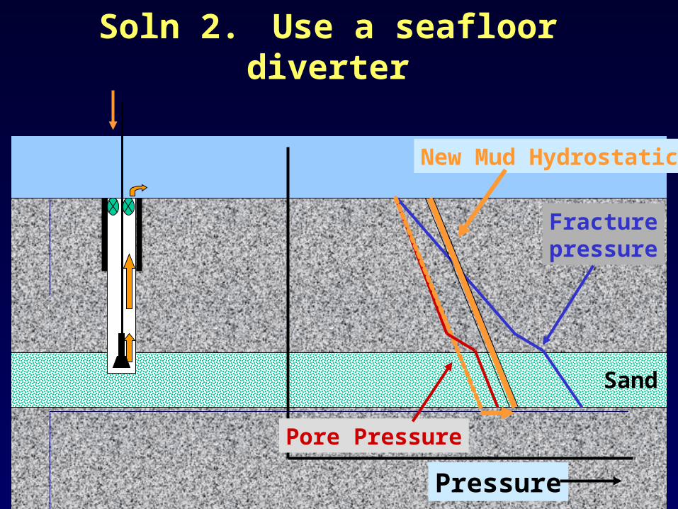
Soln 2. Use a seafloor diverter
Pressure
Sand
Pore Pressure
Fracturepressure
New Mud Hydrostatic
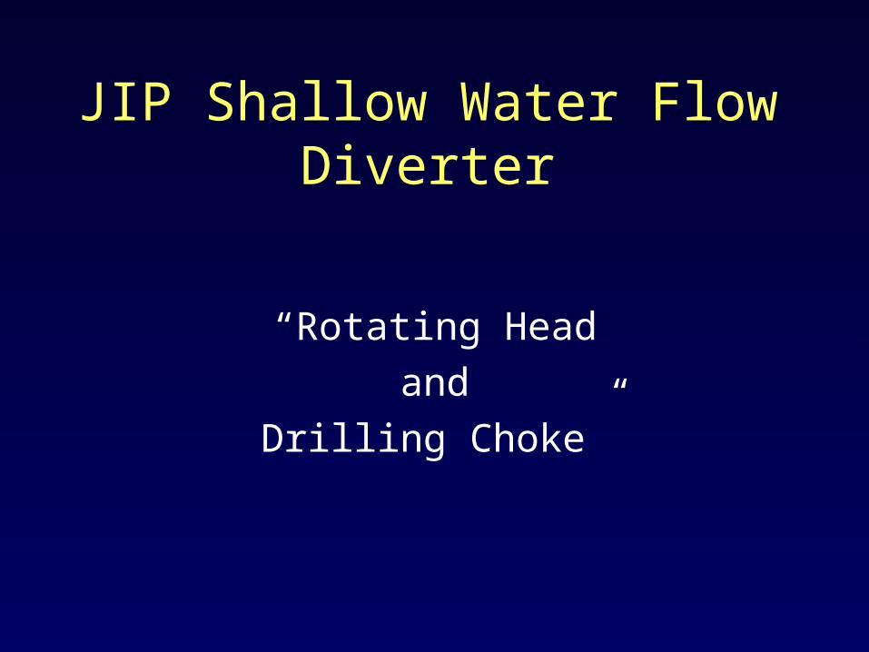
JIP Shallow Water Flow Diverter
“Rotating Head
and
Drilling Choke”
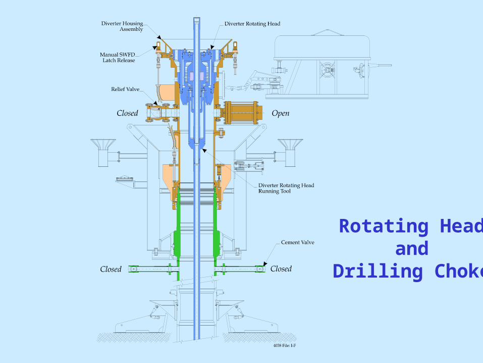
Rotating Head and
Drilling Choke
29
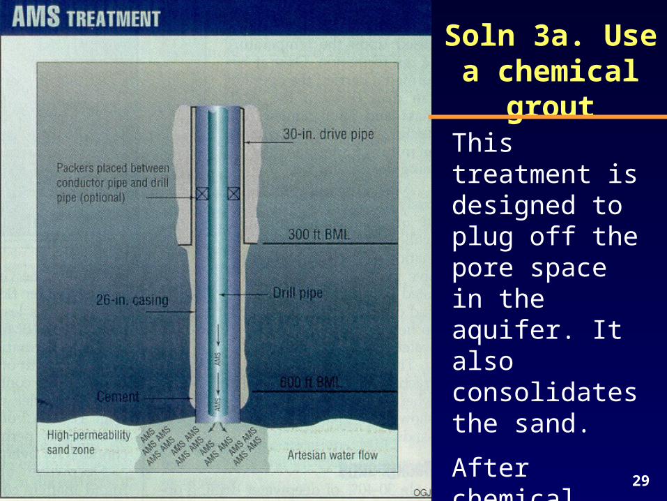
Soln 3a. Use a chemical grout
This treatment is designed to plug off the pore space in the aquifer. It also consolidates the sand.
After chemical solidifies, drilling can proceed.
30
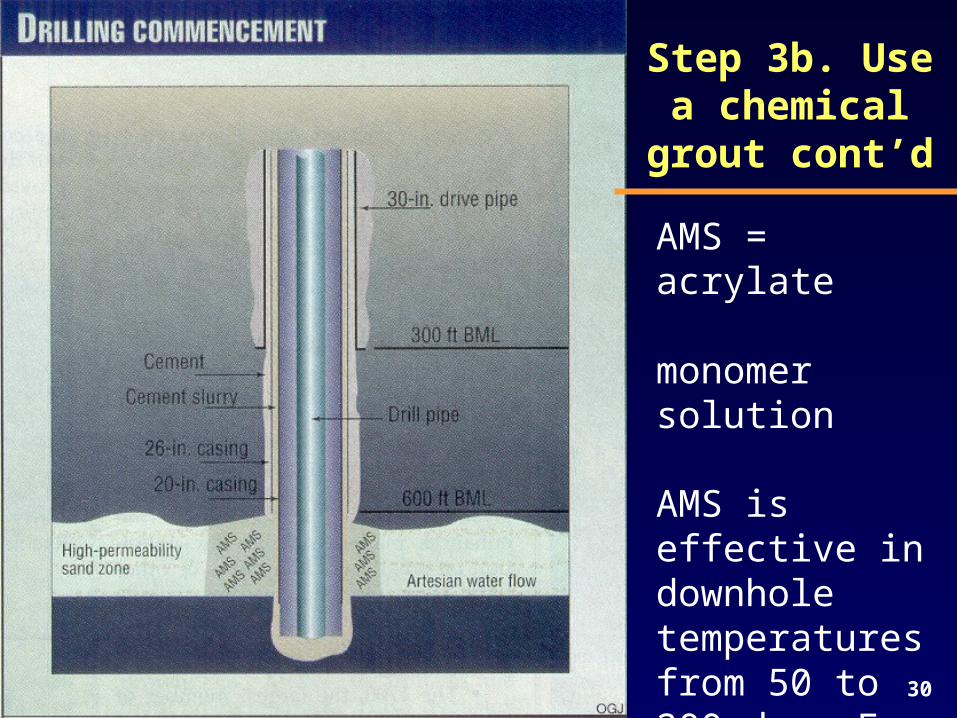
AMS = acrylate monomer solution
AMS is effective in downhole temperatures from 50 to 200 deg. F.
Step 3b. Use a chemical grout
cont’d
31
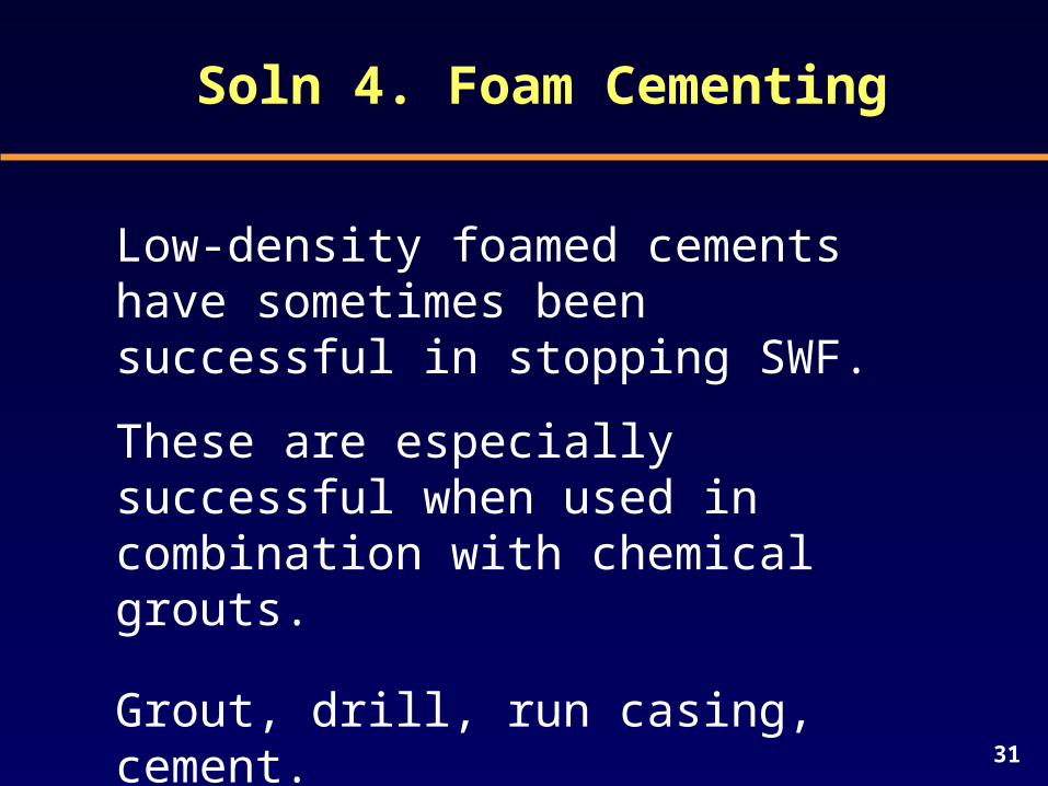
Soln 4. Foam Cementing
Low-density foamed cements have sometimes been successful in stopping SWF.
These are especially successful when used in combination with chemical grouts.
Grout, drill, run casing, cement.
OTC 8731
GU
LF
OF
ME
XIC
ODEEPWATER STAGED
RECO
VE
RY
SYS
TE
M
. .
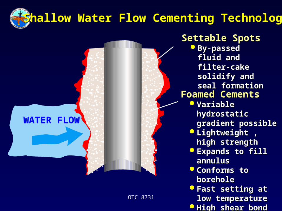
Settable SpotsSettable Spots By-passed fluid By-passed fluid
and filter-cake and filter-cake solidify and seal solidify and seal formationformation
Foamed CementsFoamed Cements Variable hydrostatic Variable hydrostatic
gradient possiblegradient possible Lightweight , high Lightweight , high
strengthstrength Expands to fill Expands to fill
annulusannulus Conforms to borehole Conforms to borehole Fast setting at low Fast setting at low
temperaturetemperature High shear bond High shear bond
supports well loadssupports well loads
Shallow Water Flow Cementing TechnologyShallow Water Flow Cementing Technology
WATER FLOW
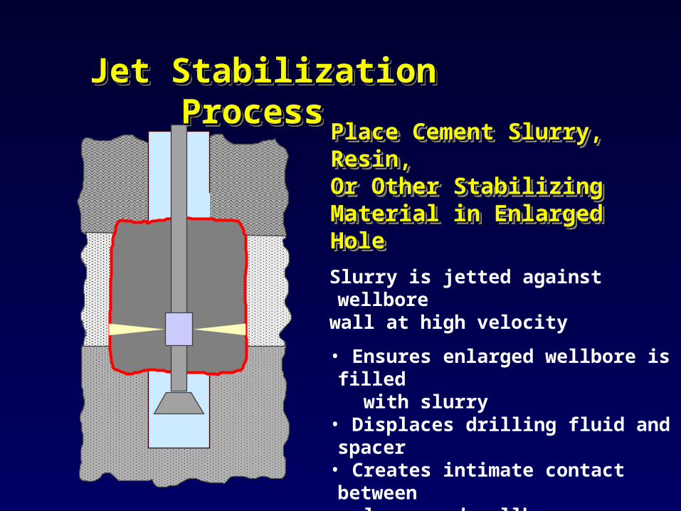
Place Cement Slurry, Place Cement Slurry, Resin, Resin, Or Other Stabilizing Or Other Stabilizing Material in Enlarged HoleMaterial in Enlarged Hole
Place Cement Slurry, Place Cement Slurry, Resin, Resin, Or Other Stabilizing Or Other Stabilizing Material in Enlarged HoleMaterial in Enlarged Hole
Slurry is jetted against wellborewall at high velocity
• Ensures enlarged wellbore is filled with slurry• Displaces drilling fluid and spacer• Creates intimate contact between slurry and wellbore• Removes filter cake
Jet Stabilization ProcessJet Stabilization Process Jet Stabilization ProcessJet Stabilization Process
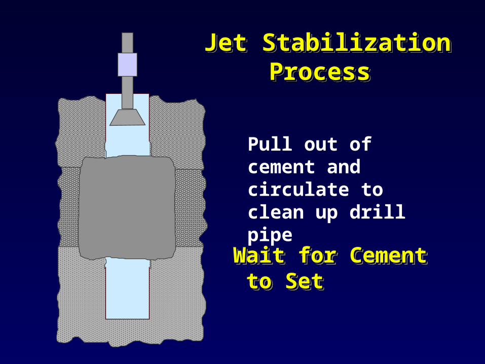
Pull out of cement and circulate to clean up drill pipe
Wait for CementWait for Cement to Setto SetWait for CementWait for Cement to Setto Set
Jet Stabilization ProcessJet Stabilization Process Jet Stabilization ProcessJet Stabilization Process
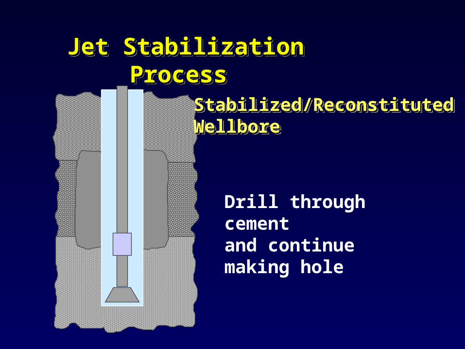
Stabilized/Reconstituted Stabilized/Reconstituted WellboreWellbore Stabilized/Reconstituted Stabilized/Reconstituted WellboreWellbore
Drill through cementand continue making hole
Jet Stabilization ProcessJet Stabilization Process Jet Stabilization ProcessJet Stabilization Process
36
Soln 5. Underbalanced drilling through the SWF zone using
coiled tubing
A joint industry project is underway to evaluate and develop this technique.
37
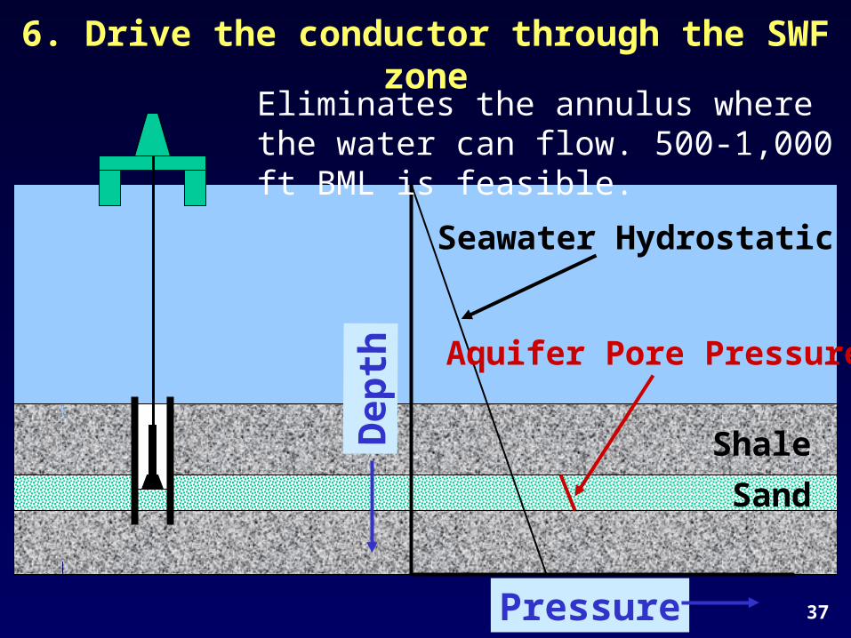
6. Drive the conductor through the SWF zone
Pressure
Dep
th
Seawater Hydrostatic
Shale
Sand
Aquifer Pore Pressure
Eliminates the annulus where the water can flow. 500-1,000 ft BML is feasible.
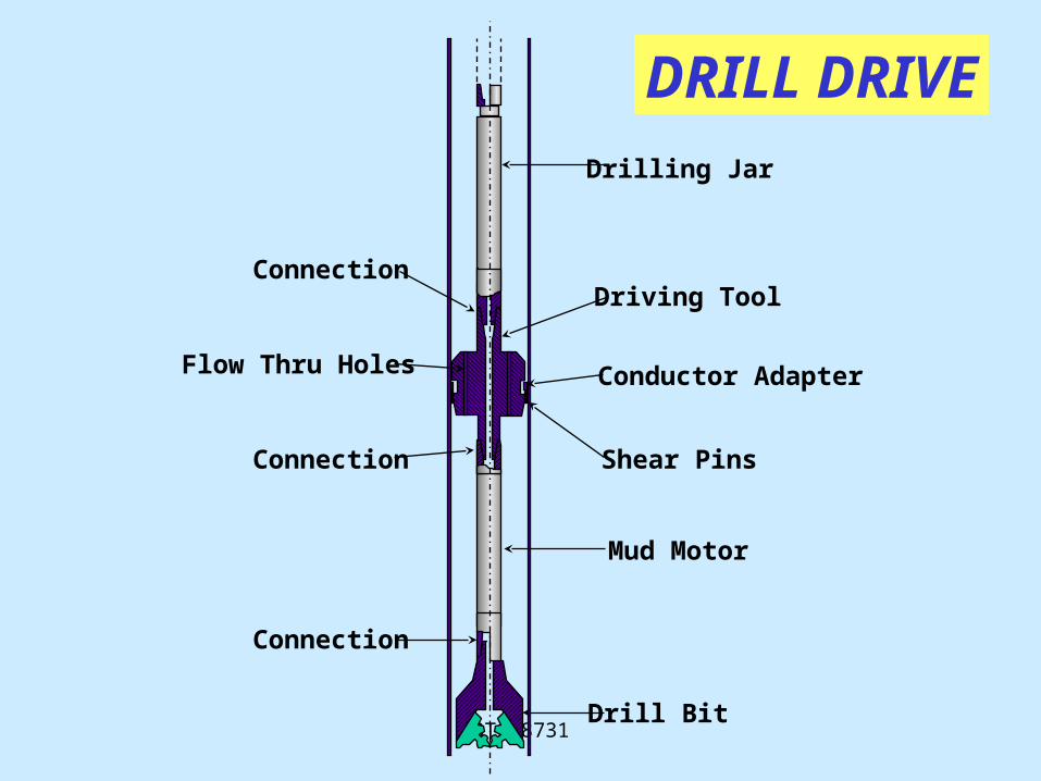
OTC 8731
Connection
Flow Thru Holes
Connection Shear Pins
Conductor Adapter
Driving Tool
Connection
Mud Motor
Drill Bit
Drilling Jar
DRILL DRIVE
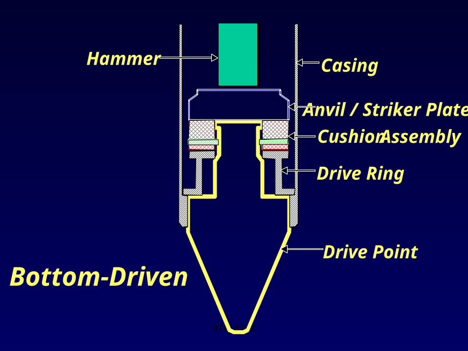
OTC 8731
Casing
Anvil / Striker Plate
Drive Ring
Drive Point
Hammer
Cushion Assembly
Bottom-Driven
40
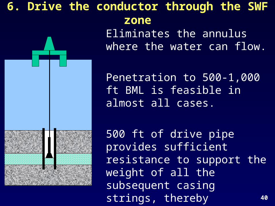
6. Drive the conductor through the SWF zone
Eliminates the annulus where the water can flow.
Penetration to 500-1,000 ft BML is feasible in almost all cases.
500 ft of drive pipe provides sufficient resistance to support the weight of all the subsequent casing strings, thereby preventing settling and casing buckling, even if SWF reoccur.

41
TheEnd