1 optical transport network (otn) itu-t standard g.709 paper: andreas schubert: ”g.709 – the...
TRANSCRIPT

1
Optical Transport Network (OTN)
ITU-T standard G.709Paper: Andreas Schubert: ”G.709 – The Optical
Transport Network (OTN)”
http://www.jdsu.com/product-literature/g709otn_wp_opt_tm_ae.pdf

2
Overview
• Literature• Motivation for an optical transport network standard• Properties of OTN• G.709 Interface standard• OTN framing structure - whats the point of all this overhead.• Tandem connection monitoring• Forward Error Correction (FEC)• OTN switching

3
Literature
• ITU-T– G.709 “Interface for the optical transport network (OTN)”
• The most referenced standard in OTN• Describes Intra and inter –domain interfaces • Framing and framing structure
– G.872 - Architecture of optical transport networks• Described from a network level viewpoint• Describes network layers
• Andreas Schubert “White paper”– What is a white paper?– G.709 - The Optical Transport Network (OTN)

4
Why not IP directly over WDM?
• IP-WDM, a buzzword from the late 90’s• Can you transport an IP-packet directly on a fiber?• Which functionality is required?
– 1………..
– 2….
– 3..
– 4..
5
Why not IP directly over WDM?
• IP-WDM, a buzzword from the late 90’s• Can you transport an IP-packet directly on a fiber?• Which functionality is required?
– 1 Clock information
– 2 Start/stop indication of packet
– 3 Error checking?
– 4 Error correction?

6
Functionality added to IP for WDM transport• Framing for the physical layer transport
– May e.g. be Ethernet
• Monitoring of errors and signal quality• Management for provisioning of data-paths• Fault handling, fast protection • Management of wavelengths• Management of optical network elements
– Functionality at the physical layer

7
Why OTN?
• Standard for optical networks required– Optical interconnection between equipment from different vendors– Optical interconnection between different operators
• Once called “digital wrapper”• Framing of client signal of different protocols for transport over
the physical optical layer– E.g. IP/Ethernet or IP/ATM or SDH
• Takes SDH/SONET further, enabling optical functionality – From a single to multiple wavelengths– Forward Error Correction (FEC)– What is FEC?

8
Properties of OTN
• Protocol transparency– Handles “any” protocol-stack and gives a physical layer to higher
layer protocols like e.g. IP
• Backward compatibility for existing protocols– Handles both SDH and Ethernet
• FEC– Reduces cost, improves performance
• Reduction of 3R regeneration– Allows management of all-optical network elements

9
Interfaces
• Inter-domain interfaces (IrDI)– Location between networks of two operators
– Location between sub-networks of two vendors in the same operator domain
– The location within the sub-network of one vendor
– 3R regeneration – Why?
• Intra-Domain interfaces (IaDI)– The location between the equipment of an individual manufacturer’s
sub-network
– Transparent network
10
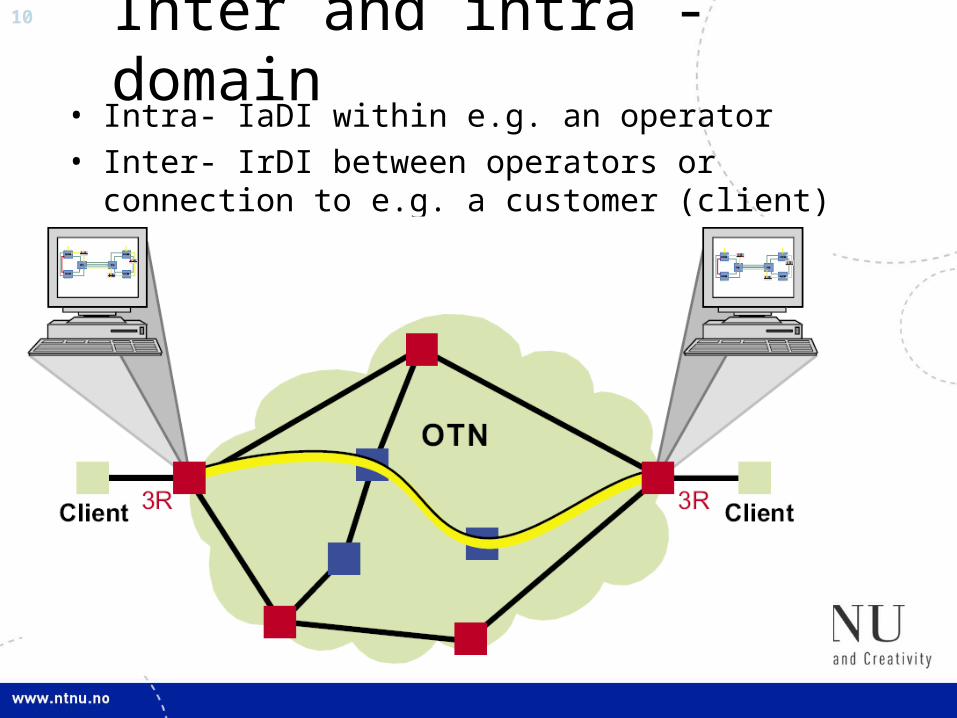
Inter and intra -domain• Intra- IaDI within e.g. an operator• Inter- IrDI between operators or connection to e.g. a
customer (client)
11
Transport of a client signal
• Over-Head (OH) added to form optical channel payload unit (OPU)
• OH to OPU forming optical channel data unit (ODU)• Additional OH plus FEC are added to form the optical
channel transport unit (OTU)• Adding further OH creates an OCh which is carried
by one color (wavelength)

12
OTN layer structure
• OCh = Optical channel• OMS = Optical Multiplex section• OTS = Optical Transmission Section

13
OTN hierarchy Client
OH Client
OH OPUk
OH ODUk FEC
OCh payload
Client
OPU
ODU
OTU
OChannel
OMS payload
OTS payload
OCCp OCCp OCCp OCCp OCCp OCC
Non
A
ssoc
iate
d ov
erhe
ad

14
In-band and out of band OH
• Non-associated OH (out of band) may be added to OCh enabling management of multiple colours in OTN.
• Optical Multiplex Section (OMS) – Multiplex of OCh’s
• Optical Transmission Section (OTS)– The transmission medium, I.e. the fibre

15
Optical channel structure (OCh)
ClientODU-OH
OP
U-O
HOTU-OHFAS
FEC
1
2
3
4
1 7 8 14151617 3824 3825 4080
RES
PT
PSI
RES TCM/ACT FTFLTCM6 TCM5 TCM4
TCM3 TCM2 TCM1 PM EXP
RESAPS/PCCGCC2GCC1

16
Optical Payload Unit (OPU)
• Framing of client signal– May be of any protocol, e.g. SONET/SDH, GFP, IP, GbE
• Payload Structure Identifier (PSI)– 256 Byte message
– Justification bits for asynchronous mapping of client signal
– PSI0 contains Payload Type (PT) (single byte) identifying type of payload
– RES – Bytes Reserved for future use
RES
PT
PSI
17
Optical channel Data Unit (ODU) functionality• Tandem Monitoring (TCM)
– Hierarchical error checking using parity bytes– Allows up to six tandem connections, nesting and overlapping
• Path Monitoring (PM)– Monitoring of particular sections – Fault location
• General Communication Channels (GCC)– Typically Management communication
• Automatic Protection Switching (APS)– Protection switching at one or more levels– What is protection switching?

18
ODU-k: Defined for several bitrates
• -k is a number defining the bitrate• Originally defined bitrates
– ODU1: 2.5 Gb/s
– ODU2: 10 Gb/s
– ODU3: 40 Gb/s
• Recently defined/to be defined– ODU0: 1 Gb/s (Matches Gigabit Ethernet)
– ODU4: 100 Gb/s (Matches 100 Gigabit Ethernet)

19
ODU in OTN hierarchy Client
OH Client
OH OPUk
OH ODUk FEC
OCh payload
Client
OPU
ODU
OTU
OChannel
OMS payload
OTS payload
OCCp OCCp OCCp OCCp OCCp OCC
Non
A
ssoc
iate
d ov
erhe
ad

20
ODU OH
• PM - Path Monitoring, contains three sub-fields• TCM1-TCM6
– OH for six independent TCM’s– Contains similar sub-fields as PM
• TCM/ACT Activation/deactivation of TCM• GCC
– Communication between network elements (management), two channels
• APS/PCC– Automatic Protection Switching– Protection Communication Channel
• RES Reserved for future use• EXP Experimental use• FTFL - Fault Type and fault location Channel
– Fault status, type and location– Related to TCM span
RES TCM/ACT FTFLTCM6 TCM5 TCM4
TCM3 TCM2 TCM1 PM EXP
RESAPS/PCCGCC2GCC1

21 Tandem Connection monitoring• Six levels, nested or cascaded connections• Nested: A1-A2/B1-B2/C1-C2 and A1-A2/B3-B4
Cascaded: B1-B2/B3-B4• Carriers may maintain their own service level
agreement (SLA) – What is a SLA?
Figure from G.709 standard

22
TCM and PM overhead structure
TTI BIP-8
SAPI
DAPI
Operatorspecific
BDIBEI STAT
BDIBEI STAT
PM
TCM
Trail-Trace Identifier
Source accessPoint Identifier
Destination accessPoint Identifier
- Country of origin- Network operator- Administrative details
Parity
Signal failure UpstreamSingle bit
BackwardError IndicationInfo.
Maintenance Signal present

23
FTFL sub-fields• Fault status information• Type and location of fault• Related to TCM span• Codes specified: No fault, Signal fail, signal degrade
24
Optical channel transport unit (OTU)
• Support transport of OTU via one or more optical channel connections
• Frame alignment Signal (FAS)– Multi Frame Alignment Signal (MFAS)
– ODU frames may span multiple OTU frames
– TTI and TCM-ACT (activation) signals requires multiple ODU-frames for being processed
• Forward Error Correction (FEC)

25
OTU OH structure
FAS MFAS SM GCC RES
FAS OTU
Section Monitoring
=PM + IAE bitIAE: Ingress inform egressIncoming Alignment error on signal
Comm. OTU term. Points(management)
REServedFor future use

26
Forward Error Correction (FEC)
• Added at the end of the OTU-frame• Very important property of OTN, why?• Detection of errors• Correction of errors through redundant information• Allows lower signal quality • I.e. allows larger degradation by physical
impairments
ClientODU-OH
OP
U-O
HOTU-OHFAS
FEC
1
2
3
4
1 7 8 14151617 3824 3825 4080

27
Physical impairments to be compensated
• Linear (explain these)– Attenuation
– Noise
– Dispersion: Chromatic, mode and polarisation
• Non-linear– Four wave mixing
– Self phase modulation
– Cross phase modulation

28
FEC gain
• Bit Error Rate (BER) improvement example: 10-4 -> 10-15
• How can BER be defined, and how is it measured?• Gain in power level approx 5 dB for 7 % FEC• Reduce amount of 3R regenerators• Use existing 2.5 Gb/s links for 10 Gb/s• Early warning when degradation of link quality start to
appear• Longer spans between amplifiers in subsea-systems
(lower cost)

29
FEC algorithms• Performance increase depends on algorithm and
amount of overhead (redundancy information)• Standardized algorithms, G.709. Reed-Solomon
based

30
OTN switching• Client signals of different bitrates can be multiplexed
into higher bitrate OTN signal.• Switching down to Gigabit granularity (ODU-0)

31
Summary OTN
• Management to the high bandwidth WDM network– SDH/SONET single wavelength, OTN – multiple wavelengths– Builds on management functionality from SDH/SONET– Monitoring functionality– GCC channels for management communication
• Transparency to other protocols, e.g. IP– Wrap whatever you like
• FEC compensates physical impairments, increases cost-efficiency
• OTN switching is being deployed• OTN transmission and switching market is increasing rapidly