1 of 35 nhdot memorial bridge replacement project · pdf file550 2 of 35 nhdot memorial bridge...
TRANSCRIPT
550
1 of 35
NHDOT
Memorial Bridge Replacement Project
13678F
Final RFP
Volume II – Book 3
Special Provisions June 10, 2011
S P E C I A L P R O V I S I O N
AMENDMENT TO SECTION 550 -- STRUCTURAL STEEL
PART I of III -- PROJECT-SPECIFIC REQUIREMENTS
This special provision amends Section 550 and applies to the coating of new structural steel as
shown on the plans or otherwise specified to be painted. This special provision consists of three parts.
Part I amends the general requirements of Part II with project-specific requirements. Part III contains
Section 708, Paints.
Amend 550.3.13.1.2 to read:
1.2 DESCRIPTION OF BRIDGE(S)
1.2.1 The description of newly fabricated structural steel to be painted is stated herein. All
descriptions regarding the bridge(s) and surface area(s) are intended to be generally, but not guaranteed
to be precisely, accurate.
1.1.2.1 Br. No. 246/083 US Rte 1 over Scott Avenue in the City of Portsmouth, NH. This bridge
is immediately adjacent to the Memorial Bridge and part of the contract items, as described in the
contract documents.
1.1.2.2 Br. No. 247/084 US Rte 1 Memorial Bridge over the Piscataqua River connecting the
City of Portsmouth, NH with the Town of Kittery, Maine. The Kittery approach spans are
considered part of this bridge for work items as described in the contract documents.
DESCRIPTION OF BRIDGES - SUMMARY TABLE 1.2.1
Town Br. No. Route over No. spans & length
Portsmouth, NH 246/083 US Route 1 Scott Avenue 2 span girder - 125± ft
Portsmouth, NH -
Kittery, ME 247/084
US Route 1
(Memorial Bridge) Piscataqua River
3-truss spans @ 300± ft,
total 900± ft, plus 300± ft
Kittery approach span
viaduct
550
2 of 35
NHDOT
Memorial Bridge Replacement Project
13678F
Final RFP
Volume II – Book 3
Special Provisions June 10, 2011
Amend 550.3.13.1.3 to read:
1.3 SCOPE OF WORK
SCOPE OF WORK - SUMMARY TABLE 1.3
Item number. & structural steel surfaces to be painted,
as shown on the plans
Surface
Preparation
Required Paint
System Final Color
SCOTT AVENUE BRIDGE
550.101 Structural Steel (all interior steel surfaces)
550.201 Bridge Shoes
SSPC-SP10
& SC 2
3-coat system C
(with Finish #1)
Dark Green
Fed # 24109
550.101 Structural Steel (fascia surfaces of fascia
beams)
SSPC-SP10
& SC 2
4-coat system C
with Finish
#1 & #3)
Dark Green
Fed # 24109
MEMORIAL BRIDGE
550.1021 Structural Steel (Lift Span - Truss)
550.1031 Structural Steel (Fixed Spans -Truss)
550.1041 Structural Steel (Towers)
SSPC-SP10
& SC 2
4-coat system C
with Finish
#1 & #3)
Dark Green
Fed # 24109
550.1071 Structural Steel (Kittery Approach. Spans)
(fascia surfaces of fascia beams)
SSPC-SP10
& SC 2
4-coat system C
with Finish
#1 & #3)
Dark Green
Fed # 24109
550.1071 Structural Steel (Kittery Approach. Spans)
(all interior structural steel surfaces)
SSPC-SP10
& SC 2
3-coat system C
(with Finish #1)
Dark Green
Fed # 24109
550.1022 Structural Steel (Lift Span -Floor Framing)
550.1032 Structural Steel (Fixed Span -Floor Framing)
550.202 Bridge Shoes (Lift Truss Span)
550.203 Bridge Shoes (Fixed Truss Spans)
550.204 Bridge Shoes (Kittery Approach Spans)
SSPC-SP10
& SC 2 3-coat system E
Black
Fed # 27038
1.3.1 Surfaces to be painted. All new steel surfaces, including main components and
appurtenances, shall be cleaned and painted, as shown on the plans or as described herein for the
applicable item. See Table 1.3.
1.3.1.1 Finished bearing surfaces. When bearings are to be painted, the surface preparation and
painting shall include the machined finish for rolling (but not for sliding) surfaces.

550
3 of 35
NHDOT
Memorial Bridge Replacement Project
13678F
Final RFP
Volume II – Book 3
Special Provisions June 10, 2011
1.3.2 Required Surface Preparation. All steel surfaces to be painted shall be cleaned in
conformance to SSPC-SP10 and the chloride level remediated to SC 2 (see Section 3.2.6.7).
1.3.3 Required Paint System
1.3.3.1 The complete paint system shall be shop applied to the structural steel as described in Table
1.3 and shown on the plans, except for areas masked for field welding or bolted connections (see Section
3.4.12), or as directed. Field bolted connections and retrofit plates shall receive one application of
primer prior to installation of the member, and the remaining coats of the system after installation. New
top flange surfaces to be embedded in deck concrete shall receive a light rust preventative dust coat of
0.5 to 1.5 mils (13-38 microns) of primer only. Beam ends to be encased in back wall concrete (if
applicable) shall receive the full paint system.
1.3.3.1.1 Steel surfaces with a non-skid finish shall meet the requirements of 2.1.1 and 3.4.13.
1.3.3.2 The finish color and paint system for Items 550.xxx SHALL BE THE SAME AS FOR ITEM
556, Painting Existing Structural Steel, if applicable. See Table 1.3. It is the Design-Builder’s
responsibility to coordinate suppliers to achieve this requirement.
1.3.3.3 The finish color shall be as shown in Table 1.3.
Add to 550.1.7.3 the following:
Batch samples for testing are not required. Provide to the Materials Lab a certificate of
conformance from the coating manufacturer including a batch analysis for each production lot for each
coating.
Add the following to 2.2. Coatings:
10. Coatings containing lead or chromium, other than naturally occurring trace amounts
associated with the coating pigments, are not permitted.
11. A dry film sample of each coat (e.g. primer, intermediate, and finish) shall be tested by a
laboratory certified by AIHA or A2LA under the ELLAP program (Environmental Lead
Laboratory Accreditation Program) to determine its total lead content. The analytical test
method shall be sufficient to provide a minimum detection limit no greater than 100 ppm.
Acceptable test methods include: ASTM D 3335 (Atomic Absorption Spectroscopy), AOAC
974.02 (Lead in Paint), and ASTM E1613 (Inductively Coupled Plasma (ICP)
spectroscopy).
12. The percentage of total lead in each coating shall be reported to the Department and shall not
exceed 0.01 percent (100 ppm).
13. A written certificate of conformance shall be submitted to the Department for the coatings
supplied stating that the paint is “lead-free”.

550
4 of 35
NHDOT
Memorial Bridge Replacement Project
13678F
Final RFP
Volume II – Book 3
Special Provisions June 10, 2011
Revision
date LIST OF REVISIONS (generally stated - see specification for actual wording)
11/18/10 Update Part III - Section 708 approved paint systems.
4/19/10 2.2 - Reduce maximum total lead content from 600 ppm to 100 ppm;
2/11/10 2.2.9 - Change color number for dark brown to 20062.
Update Part III - Section 708 approved paint systems.
9/25/09 2.2 - Add requirement coatings with more than trace amounts of lead and chromium
are not permitted;
2.2 - Add requirement to test for lead, report results to the Department, limit total
lead content to 600 ppm max., and submit "lead-free" certificate of conformance
for coatings;
10/24/08 Update Part III - Section 708 approved paint systems.
10/24/07 3.1.4 - add wording that quality control be performed daily and per SSPC-QP1
3.6.2 - add requirement to provide lighting for inspectors
4.1.2 (4) - add requirement for neat and uniform final appearance
6/8/07 4.1.2 (3) - add requirement to clean off concrete spatter and drippings
2.2.3 - add VOC max limit of 2.8 lb/gal (340 g/L) for intermediate and topcoats.
10/5/06 708 - update QPL
1/13/06 Remove proprietary reference to 3M Scotch-Brite Clean and Strip discs
4/11/05 2.1.2 - add requirements for non-skid grain
2.2 - add Paint System E
3.4.11 (2) - reword the number of DFT readings to be taken by QA inspection
3.4.13 - add requirements for a non-skid walking surface finish
3.2.11 - extend the warranty to 3 years and clarify the definition of coating failure.
708 - update QPL

550
5 of 35
NHDOT
Memorial Bridge Replacement Project
13678F
Final RFP
Volume II – Book 3
Special Provisions June 10, 2011
PART II of III -- GENERAL REQUIREMENTS
Part II states general requirements for painting new structural steel as amended by project
specific requirements of Part I.
Amend 3.2.3 to read:
3.2.3.1 Shop painting certification. Fabricators supplying shop applied painted or metalized steel
products shall be certified with the American Institute of Steel Construction (AISC) Sophisticated Paint
Endorsement (SPE), or with the Society for Protective Coatings (SSPC) Quality Procedure 3 “Standard
Procedure for Evaluating Qualifications of Shop Painting Contractors (QP3).
3.2.3.2 Field painting contractor certification. Painting contractors and subcontractors shall be
certified by the Society for Protective Coatings (SSPC) Painting Contractor Certification Program
(PCCP) to the requirements of SSPC-QP1 for all field painting work, and to the requirements of SSPC-
QP2 for work involving the removal or overcoating of lead-based paint.
Amend 3.13 to read:
3.13 PAINTING NEW STRUCTURAL STEEL
OUTLINE OF SECTION 550.3.13
1 DESCRIPTION
1.1 General
1.2 Description of Bridge
1.3 Scope of Work
1.4 Regulatory Compliance
1.5 Contractor Responsibility
1.6 Reference Standards
1.7 Submittals
2 MATERIALS
2.1 Abrasives
2.2 Coatings
2.3 Equipment
3 SHOP PAINTING
3.1 General
3.2 Surface Preparation
3.3 Paint Storage Mixing & Handling
3.4 Coating Application
3.5 Repair of Damage
3.6 Inspection
4 FIELD PAINTING
4.1 General
4.2 Surface Preparation
4.3 Housecleaning
4.4 Final Acceptance

550
6 of 35
NHDOT
Memorial Bridge Replacement Project
13678F
Final RFP
Volume II – Book 3
Special Provisions June 10, 2011
4.5 One Year Anniversary Inspection
Note: The sections of this specification to follow are numbered in the manner of the outline above
without the prefix “550.3.13”, which is implied.
DESCRIPTION
1.1 GENERAL
1.1.1 General Description. This work shall consist of the cleaning, surface preparation, and
painting of new structural steel, including the proper preparation of the steel surfaces, the application,
drying, cure, and protection of coatings, both in the shop and in the field, and worker and environmental
protection, as described herein or as directed.
1.2. DESCRIPTION OF BRIDGE
(See Section 550 Part I)
1.3 SCOPE OF WORK
(See Section 550 Part I)
1.4 REGULATORY COMPLIANCE
1.4.1 Comply with the requirements of this Item and all applicable Federal, State and local laws,
codes, and regulations, including, but not limited to the regulations of the United States Environmental
Protection Agency (EPA), Occupational Safety and Health Administration (OSHA), and the New
Hampshire Department of Environmental Services (NHDES) in conformance to Section 107.
1.4.2 Identification of the items below which are of specific interest to NHDOT in no way relieves
the Design-Builder of the responsibility to comply with all OSHA and EPA requirements, nor should it
be construed that the NHDOT, the EPA, NHDES, or other State and City regulators are only interested in
these items. If a Federal, State, or City regulation is more restrictive than the requirements of this Item,
follow the more restrictive requirements.
1.5 DESIGN-BUILDER RESPONSIBILITY. The Design-Builder is responsible for performing
the requirements stated herein, whether the specification wording states this explicitly (e.g. "The Design-
Builder shall conduct all operations...") or implicitly (e.g. "Conduct all operations..."), unless the wording
specifically names a different party (e.g. 3.6.1 "The Department will inspect...").
1.6 REFERENCE STANDARDS
1.6.1 The latest edition of the following standards and regulations in effect at the time of the Bid
form a part of this Specification. A copy of the reference standards applicable to the work shall be
available at the shop painting facility and in the field.
550
7 of 35
NHDOT
Memorial Bridge Replacement Project
13678F
Final RFP
Volume II – Book 3
Special Provisions June 10, 2011
1.6.2 American Society for Testing and Materials (ASTM)
1. ASTM D3359, Standard Test Methods for Measuring Adhesion by Tape Test
2. ASTM D4138, Standard Test Method for Measurement of Dry Paint Thickness of Protective
Coating Systems by Destructive Means
3. ASTM D4285, Standard Test Method for Indicating Oil or Water in Compressed Air
4. ASTM D4414, Standard Practice for Measurement of Wet Film Thickness by Notch Gages
5. ASTM D4417, Standard Test Methods for field Measurement of Surface Profile of Blast
Cleaned Steel
6. ASTM D4541, Standard Test Method for Pull-Off Strength of Coatings Using Portable
Adhesion Testers
7. ASTM D4752, Standard Test Method for Measuring MEK Resistance of Ethyl Silicate Zinc-
Rich Primers by Solvent Rub
1.6.3 Society for Protective Coatings (SSPC)
1. SSPC-SP 1, Solvent Cleaning
2. SSPC-SP 2, Hand Tool Cleaning
3. SSPC-SP 3, Power Tool Cleaning
4. SSPC-SP 5 / NACE No. 1, White Metal Blast Cleaning
5. SSPC-SP 7 / NACE No. 4, Brush Off Blast Cleaning
6. SSPC-SP 10 / NACE No. 2, Near-White Metal Blast Cleaning
7. SSPC-SP 11, Power Tool Cleaning to Bare Metal
8. SSPC-SP 12 / NACE No. 5, Surface Preparation and Cleaning of Steel and Other Hard
Metals by High- and Ultrahigh- Pressure Water Jetting Prior to Recoating
9. SSPC-AB 1, Mineral and Slag Abrasives
10. SSPC-AB 2, Specification for Cleanliness of Recycled Ferrous Metallic Abrasives.
11. SSPC-AB 3, Newly Manufactured or Re-Manufactured Steel Abrasives
12. SSPC-PA 1, Shop, Field, and Maintenance Painting
13. SSPC-PA 2, Measurement of Dry Film Thickness with Magnetic Gages
14. SSPC-SP COM, Surface Preparation and Abrasives Commentary, SSPC Painting Manual,
Vol. 2, “Systems and Specifications”
15. SSPC-TU4, Field Methods for Retrieval and Analysis of Soluble Salts on Substrates.
16. SSPC-VIS 1, Guide and Reference Photographs for Steel Surfaces Prepared by Dry Abrasive
Blasting
17. SSPC-VIS 3, Visual Standard for Power- and Hand- Tool Cleaned Steel
18. SSPC QP1, "Standard Procedure for Evaluating Painting Contractors (Field Application to
Complex Industrial Structures)", August 1, 1998
19. SSPC QP2, "Standard Procedure for Evaluating the Qualifications of Painting Contractors to
Remove Hazardous Paint", August 1, 1995
20. SSPC-QP3, Standard Procedure for Evaluating Qualifications of Shop Painting Contractors
1.6.4 American Association of State and Highway Transportation Officials (AASHTO)
1. AASHTO Standard Specification for Highway Bridges, Division II Construction, Section 13,
Painting

550
8 of 35
NHDOT
Memorial Bridge Replacement Project
13678F
Final RFP
Volume II – Book 3
Special Provisions June 10, 2011
2. AASHTO/NSBA Steel Bridge Collaboration, S8.1-2001, Standard Specification for Coating
Systems with Inorganic Zinc-Rich Primer, November 2001
1.6.5 American Institute for Steel Construction (AISC)
1. Sophisticated Paint Endorsement (SPE)
1.6.6 Research Council on Structural Connections (RCSC)
1. Specification for Structural Joints Using ASTM A325 or A490 Bolts, Section 5(b), endorsed
by the Research Council on Structural Connections
1.7 SUBMITTALS
1.7.1 Surface Preparation/Painting Plan. Provide the following surface preparation / painting
plan to the Department for documentation in conformance to 105.02.
1. Provide written procedures covering such items as the paint manufacturer, wet and dry film
thickness, cure time between coatings, protection and treatment of faying surfaces, repair of
typical damage and defects in the coating, and other information needed to successfully
apply all coats of paint in the shop.
1.7.2 Coating Material Documentation
1. Identify the coating materials to be applied. Include the manufacturer’s name, product
names, and product numbers. Provide material product data sheets, volatile organic
compound (VOC) levels, MSD sheets, and written application instructions including mixing
requirements, specified thinners, and thinner amounts.
2. The finish coat color shall be as shown in Section 550 Part I as per Federal Standard 595 (see
2.2.(9)). Provide a 3 x 6 inch (75 x 150 mm) panel coated with the finish color to the
Department for approval prior to application.
3. Submit documentation that the complete system meets the specified standard of 708 and a
Certificate of Compliance for the paint material, in conformance to the requirements of
106.04.
4. In the event of a conflict between the manufacturer’s technical data and the requirements of
this Item, comply with this Item unless the requirements of the manufacturer are more
restrictive. In these cases, advise the Department of the discrepancies in writing, and comply
with the Department’s written resolution.

550
9 of 35
NHDOT
Memorial Bridge Replacement Project
13678F
Final RFP
Volume II – Book 3
Special Provisions June 10, 2011
1.7.3 Coating Samples for Testing
1. If required, submit one sample of each initial coating material batch to the NHDOT Bureau
of Materials and Research lab for testing and acceptance (Stickney Ave., Concord, NH
03301 Tel. 603-271-1660).
2. Provide original, unopened, one-pint (0.47 L) samples directly from the manufacturer, or 5-
gallon (18.9 L) containers directly from the jobsite. Mark all samples with the job-specific
project name and number.
3. Submit the samples a minimum of ten (10) days prior to the commencement of field painting
operations.
4. Provide samples of subsequent batches as directed by the Department throughout the course
of the project.
5. When samples are requested, paint from the respective batches cannot be used until
authorized by the Department.
MATERIALS
2.1 ABRASIVES
1. Provide abrasives that are dry and free of oil, grease, and corrosion producing, or other
deleterious contaminants. Only recyclable metal (steel or aluminum oxide) abrasives shall
be used for dry abrasive blast cleaning and shall be tested daily (or as otherwise approved) to
meet the cleanliness standards of SSPC-AB2 or AB3.
2. Provide an abrasive mixture of shot and grit that is sized to produce a sharp, angular, uniform
anchor pattern profile height of 1.0 to 3.0 mils (25 to 75 microns), unless the requirements of
the coating manufacturer are more restrictive.
3. Provide the abrasives to the jobsite in original packaging or in bulk, and store in a clean, dry
environment.
2.1.2 Non-skid grain. Grains when required for non-skid walking surfaces shall be aluminum oxide
granules passing No. 18 screen having sharp and angular surfaces similar to metal grit abrasive. The
coating manufacturer in writing shall approve the non-skid grain or recommend a comparable substitute.
2.2 COATINGS
1. Provide the type and quantity of coating materials, thinners, and cleaning solvents needed to
paint all surfaces as required (1.1.3.1). A listing of pre-approved coating systems is found in
Part III, 708 Paint.

550
10 of 35
NHDOT
Memorial Bridge Replacement Project
13678F
Final RFP
Volume II – Book 3
Special Provisions June 10, 2011
TABLE 2.2 - COATING AND FILM THICKNESS
Film thickness Film thickness
Coat Material (mils) (microns)
PAINT SYSTEM A:
Primer: 708-NH 1.70 Inorganic zinc rich 3-5 mils DFT (75-125 microns)
Intermediate: 708-NH 3.21 High build epoxy polyamide 4-6 mils DFT (100-150 microns)
Stripe coat: (Intermediate coat) Uniform Coat Uniform Coat
Finish: 708-NH 3.81 Aliphatic polyurethane 2-4 mils DFT (50-100 microns)
Total system thickness 9-15 mils DFT (225-375 microns)
PAINT SYSTEM B:
Primer: 708-NH 1.20 Organic zinc rich primer 3-5 mils DFT (75-125 microns)
Intermediate: 708-NH 3.21 High build epoxy polyamide 4-6 mils DFT (100-150 microns)
Stripe coat: (Intermediate coat) Uniform Coat Uniform Coat
Finish: 708-NH 3.81 Aliphatic polyurethane 2-4 mils DFT (50-100 microns)
Total system thickness 9-15 mils DFT (225-375 microns)
PAINT SYSTEM C:
Primer: 708-NH 1.40 Single-component moisture-cure
zinc-rich polyurethane 3-5 mils DFT (75-125 microns)
Intermediate: 708-NH 2.40 Single-component moisture-cure
aromatic polyurethane with micaceous iron
oxide
3-5 mils DFT (75-125 microns)
Stripe coat: (Intermediate coat) Uniform Coat Uniform Coat
Finish #1: 708-NH 3.41 Single-component moisture-cure
aliphatic polyurethane with micaceous iron oxide
2-4 mils DFT (50-100 microns)
Finish #2: 708-NH 3.43 Single-component moisture-cure
aliphatic polyurethane
2-4 mils DFT (50-100 microns)
Total system thickness 8-14 mils DFT (225-325 microns)
PAINT SYSTEM E:
Primer: 708-NH 1.43 Single-component moisture-cure
micaceous iron oxide zinc-rich polyurethane
3-5 mils DFT (75-125 microns)
Intermediate: 708-NH 2.42 Single-component moisture-cure
refined coal tar aromatic polyurethane with
micaceous iron oxide
4-6 mils DFT (100-150 microns)
Stripe coat: (Intermediate coat) Uniform Coat Uniform Coat
Finish: 708-NH 3.42 Single-component moisture-cure
refined coal tar aromatic polyurethane with
micaceous iron oxide
4-6 mils DFT (100-150 microns)
Total system thickness 11-17 mils DFT (275-425 microns)

550
11 of 35
NHDOT
Memorial Bridge Replacement Project
13678F
Final RFP
Volume II – Book 3
Special Provisions June 10, 2011
2. Film thicknesses shall be as shown in Table 2.2 unless the coating manufacturer’s
recommended thickness range differs. In such cases, the manufacturer shall provide written
documentation that the range cited satisfies the Department’s performance requirements.
3. Use coatings that are compliant with Federal and State VOC regulations at the time of
application. The maximum VOC limit for the State of NH is 3.5 Lb./Gal. (420 g/L) at the
time of application for zinc-rich primers and 2.8 Lb./Gal. (340 g/L) for all other coats. (See
Section 550 Part III, 708 Paint). This includes the use of any required thinners.
4. Use the same manufacturer for all coats on a given structure, including thinners and
additives. Do not co-mix coating products or components produced by different
manufacturers under any circumstances.
5. Provide each coat of paint in sufficiently contrasting color to facilitate proper coverage and
to distinguish it from cleaned steel and previously applied coatings.
6. Order all paint, thinner, and cleaning materials well in advance of intended use. Maintain an
adequate supply of all materials on site at all times so as to not delay the work.
7. Provide all paint materials in sealed, original, containers that are properly marked and
labeled to allow verification with applicable material safety data sheets, application
precautions, and instructions. Verify that the labeling includes the manufacturer’s name,
type of material, brand name, color designation, shelf life, contract or order number under
which the material has been ordered, lot and batch numbers, and quantity.
8. Provide a 3 x 6 inch (75 x 150 mm) panel coated with the finish color with the submittals.
9. The finish color, as specified in Section 550 Part I, shall match the required Federal Standard
595 Color number as follows:
SAGE GREEN Federal Color # 24227
LIGHT (ODOT) GREEN 24272
DARK (DARTMOUTH) GREEN 24109
DARK BROWN 20059
ALUMINUM 27178
LIGHT GRAY 26152
BLACK 27038
2.3 EQUIPMENT
2.3.1 Surface Preparation and Painting Equipment.
1. Provide all brushes, discs, wheels, scrapers, descalers, blast cleaning, and other surface
preparation equipment to conduct the work as specified in this Item.

550
12 of 35
NHDOT
Memorial Bridge Replacement Project
13678F
Final RFP
Volume II – Book 3
Special Provisions June 10, 2011
2. Use equipment and materials that are clean and sized properly to accomplish the work,
including the required surface profile and finish as required by this Item.
3. Provide paint brushes, rollers, daubers, and spray equipment to conduct the work as specified
in this Item.
2.3.2 Personal Protective Equipment.
1. Provide all of the necessary personal protective equipment (PPE), such as respirators, for
workers to assure protection from hazards during surface preparation, coating application,
and clean-up activities. Make the equipment available for use by one Department
Representatives per shift
2. Repair or replace PPE as required to assure that it continues to provide its intended purpose.
2.3.3 Inspection Equipment
1. Provide all of the inspection and testing equipment needed, for use in the shop or in the field,
to verify the quality of the entire surface preparation and painting process, including mirrors
to inspect hard to reach areas.
2. Make the equipment available for use by the Department.
SHOP PAINTING
3.1 GENERAL
3.1.1 Provide all materials, apparatus, and labor necessary to perform the scope of work whether or
not the material or apparatus is specifically identified in this Item. Conduct all surface preparation and
painting operations in a neat and workmanlike manner to the satisfaction of the Department. At the
completion of the work painted surfaces shall be clean, undamaged, and present an acceptable
appearance to the Department.
3.1.2 Specifications. The work shall be performed in conformance to the Contract requirements, the
reference standards (1.6), and the coating manufacturer's instruction, respectively.
3.1.3 Safety. Conduct all work in strict conformance to the relevant OSHA regulations and the
safety and protection requirements stipulated by equipment and material manufacturers.
3.1.4 Quality Control. The applicator (i.e. fabricator or field painting contractor) is required to
conduct and document quality control inspection of the cleaning and painting operations on a daily basis
by an individual meeting the requirements of SSPC QP1, including at a minimum, all measurements
required by SSPC QP1 and those specified in 3.6, including ambient conditions, surface profile, surface
cleanliness, dry film coating thickness, and visual inspection for coating defects.

550
13 of 35
NHDOT
Memorial Bridge Replacement Project
13678F
Final RFP
Volume II – Book 3
Special Provisions June 10, 2011
3.1.5 Technical representation by coating manufacturer
3.1.5.1 Arrange for a technical representative (not a sales representative) of the coating manufacturer
to make one visit of the work at the project startup if necessary to inspect the work in the shop and in the
field to verify that the quality of surface preparation and cleaning are satisfactory for the coating system,
that the mixing and application are satisfactory, and that the coating system will perform as expected.
3.1.5.2 Have the manufacturer summarize the results of the inspection in writing, together with
recommendations. Provide the report to the Department within one week of the representative’s visit.
3.2 SURFACE PREPARATION
3.2.1 Surface Preparation Plans. Prepare all surfaces in conformance to the requirements of this
Item, and the approved Surface Preparation/Painting Plan provided under 1.7, Submittals.
3.2.2 Grinding.
3.2.2.1 Corners. All corners of sheared or flame cut edges of members to be painted shall be blunted
or flattened, i.e. chamfered to a small 45 chamfer (approximately 1/16 inch (2 mm), by passing a grinder
or other suitable devise along the corner, normally in a single pass, prior to blast cleaning.
3.2.2.2 Flame-cut edge surfaces. All flame-cut edge surfaces of members to be painted shall be
conditioned before blasting to achieve the proper profile by grounding to bright metal to remove the
hardened flame cut surface. Light grinding is generally sufficient to remove this hardened material and is
only necessary if the hardness interferes with achieving the desired profile during blast cleaning.
3.2.3 Steel defects and weld irregularities. All visually evident detrimental surface imperfections
(e.g. fins, tears, scabs, projections, slivers, and weld spatter) that are present on any steel member shall be
removed by grinding to produce an acceptable surface. When surface imperfections discovered after
blast cleaning are removed, the profile of the repair area shall be restored by blast cleaning or by
mechanical tools in conformance to SSPC-SP11. The cost shall be subsidiary to Item 550.
3.2.4 Compressed Air Cleanliness
1. Provide compressed air that is free from moisture and oil contamination.
2. Conduct a white blotter test in conformance to ASTM D 4285 to verify the cleanliness of the
compressed air. Conduct the test at least once per shift for each compressor system.
Sufficient freedom from oil and moisture is confirmed if soiling or discoloration is not
visible on the paper.
3. If air contamination is evidenced, change filters, clean traps, add moisture separators or
filters, or make other adjustments as necessary to achieve clean, dry air.
3.2.5 Ambient Conditions. Do not conduct final surface preparation which exposes bare steel under
damp environmental conditions, or when the surface temperature is less than 5 F above the dew point

550
14 of 35
NHDOT
Memorial Bridge Replacement Project
13678F
Final RFP
Volume II – Book 3
Special Provisions June 10, 2011
temperature of the surrounding air, except as permitted otherwise by the coating manufacturer. See
3.4.5(3).
3.2.6 Surface Cleaning Requirements - Steel Substrates. Section 550, Part I, identifies the degree
of cleaning required for the project. Definitions for the specified degree(s) of cleaning are provided
below:
1. SSPC-SP 1 Solvent Cleaning
a) Remove all visible oil, grease, dust, soil, drawing and cutting compounds, and other
soluble contaminants from the surface in conformance to SSPC-SP 1, Method 4.1.1 only,
prior to coating removal (with emphasis on using clean rags or brushes).
b) Only use solvents or detergents that are acceptable to the coating manufacturer in writing
and the Department.
2. SSPC-SP 2 Hand Tool Cleaning
a) Upon approval of the Department, use scrapers, putty knives, wire brushes, chipping
hammers and other similar tools to thoroughly clean any surfaces that cannot be
adequately addressed using abrasive blasting or power tool cleaning. Comply with the
requirements of SSPC-SP 2 to remove all loose mill scale, loose rust, loose paint, and
other loose foreign matter on a best effort basis.
b) It is not intended that adherent mill scale, rust, and paint be removed by this process.
Mill scale, rust, and paint are considered to be adherent if they cannot be removed by
lifting with a dull putty knife.
c) SSPC-VIS 3 may be used as an aid in determining the quality of cleaning.
3. SSPC-SP 3 Power Tool Cleaning
a) Use power assisted hand tools such as sanding discs or non-woven open-web abrasive
rotary discs, wire brushes, needle guns, or similar tools to thoroughly clean corrosion and
disbonded coating on surfaces specified in 1.1.3, Scope of Work. Comply with the
requirements of SSPC-SP 3 to remove all loose mill scale, loose rust, loose paint, and
other loose foreign matter.
b) It is not intended that adherent mill scale, rust, and paint be removed by this process.
Mill scale, rust, and paint are considered adherent if they cannot be removed by lifting
with a dull putty knife.
c) Feather the coating surrounding each prepared area to provide a smooth tapered
transition into the surrounding existing intact coating. Verify that the edges of the
coating around the periphery of the prepared areas are tight and intact by probing with a
putty knife in conformance to the requirements of SSPC-SP3.

550
15 of 35
NHDOT
Memorial Bridge Replacement Project
13678F
Final RFP
Volume II – Book 3
Special Provisions June 10, 2011
d) SSPC-VIS 3 may be used as an aid in determining the quality of cleaning.
4. SSPC-SP 7 Brush-off Blast Cleaning
a) When abrasive blast cleaning preparation of the newly applied coating is required for the
purposes of overcoating or repair, thoroughly clean all surfaces designated by the
Department. Comply with the requirements of SSPC-SP 7 to remove all loose paint,
loose rust, loose mill scale, and other foreign matter. Verify that the surfaces have been
exposed to the abrasive and that the surfaces are densely and uniformly roughened.
b) It is not intended that adherent paint be removed by this process. Paint is considered to
be adherent if it cannot be removed by lifting with a dull putty knife. Verify that the
edges remaining paint are feathered.
c) Unless restricted otherwise by the Department, accomplish the SP 7 degree of cleaning
using any of the following: dry blast cleaning with recyclable abrasives, wet abrasive
blast cleaning, water jetting with abrasive injection, or vacuum blast cleaning.
d) SSPC-VIS 1 may be used as an aid in determining the quality of cleaning.
5. SSPC-SP 11 Power Tool Cleaning to Bare Metal
a) Use power assisted hand tools such as needle guns, Roto peening equipment, or similar
tools to thoroughly clean all surfaces specified in Section 550, Part I. Comply with the
requirements of SSPC-SP 11 to remove all visible oil, grease, dirt, dust, mill scale, rust,
paint, oxide, corrosion products, and other foreign matter. Slight residues of rust and
paint may be left in the lower portions of pits if the original surface is pitted.
b) Provide a minimum surface profile of 1 mil (25 microns) on all prepared surfaces or a
profile of greater depth if required by the coating manufacturer or the Department.
Measure the surface profile using the Testex Replica Tape in conformance to ASTM
D4417.
c) SSPC-VIS 3 may be used as an aid in determining the quality of cleaning.
6. SSPC-SP 10 Near-White Blast Cleaning
a) Thoroughly blast clean all surfaces specified in 1.3, Scope of Work. Comply with the
requirements of SSPC-SP 10 to remove all visible oil, grease, dirt, dust, mill scale, rust,
paint, oxides, corrosion products, and other foreign matter, except for staining.
b) Provide a sharp, angular, uniform surface profile of 1.0 to 3.0 mils (25 to 75 microns) for
abrasive blast cleaning unless the requirements of the coating manufacturer are more
restrictive. Measure the surface profile using extra course Testex Replica Tape in

550
16 of 35
NHDOT
Memorial Bridge Replacement Project
13678F
Final RFP
Volume II – Book 3
Special Provisions June 10, 2011
conformance to ASTM D4417, Method C, at least once per shift, and when the abrasive
mixture is changed.
c) Allow staining to remain on no more than 5 percent of each nine square inch increment
of surface area. Acceptable staining is limited to light shadows, slight streaks, or minor
discolorations caused by stains of rust, stains of mill scale, or stains of previously
applied paint.
d) Accomplish the SP 10 degree of cleaning using dry blast cleaning with recyclable metal
abrasives. Allow the surface to thoroughly dry prior to painting, and apply the primer
before any visible rusting occurs.
e) SSPC-VIS 1 shall be used as an aid in determining the quality of cleaning.
7. Remediation of Chlorides
a) Verify that residual chloride levels on the structural steel (e.g. in previously rusted areas
as well as unrusted areas) are remediated to a surface cleanliness condition of SC-2 (7
g/cm2) in accordance with SSPC-SP12, as determined by the Chlor*Test ,
manufactured by Chlor*Rid International Inc. (Tel. 800-422-3217).
b) Methods of chloride removal may include, but are not limited to, steam cleaning or
pressure washing and scrubbing, reblasting, or blast cleaning with blends of fine and
course abrasives. Describe the proposed method(s) of chloride remediation in the
submitted Surface Preparation/Painting Plan.
c) Test for chlorides at a minimum frequency of two representative locations per project.
Test locations are to be determined by the Department.
d) If unacceptable levels of chlorides remain, test at a greater frequency, and reclean the
affected areas until acceptable results are achieved.
3.3 PAINT STORAGE, MIXING, AND HANDLING
3.3.1 Paint Storage
1. Store all paint, thinners, and solvents in conformance to OSHA regulations and the
requirements of the paint manufacturer. Store the paint and solvents under cover, out of
direct sunlight, and protected from vandalism.
2. Maintain the storage temperature between 40 F and 90 F (5 C and 33 C), unless the re-
quirements of the manufacturer are more restrictive.
3. Maintain MSD sheets for all materials.
550
17 of 35
NHDOT
Memorial Bridge Replacement Project
13678F
Final RFP
Volume II – Book 3
Special Provisions June 10, 2011
3.3.2 Mixing and Thinning of Coating Materials
1. Verify that the paint to be mixed has not exceeded its shelf life. When required by the
manufacturer, warm paints stored at less than 50 F (10 C) to above 50 F (10 C) prior to
mixing.
2. Utilize proper ventilation in the mixing area to prevent injury to workmen or the accumula-
tion of volatile gases.
3. Mix all coatings in conformance to the requirements of the coating manufacturer using
mechanical equipment such as a Jiffy mixer. Do not create a vortex when using the power
mixer.
4. Do not thin any paints unless approved in writing by the paint manufacturer and the
Department. If thinning is required and authorized, use only those types, brands, and
amounts of thinner stipulated by the coating manufacturer. Carefully measure the amount of
thinner added. Do not “eye ball.”
5. Strain materials after mixing to remove agglomerations.
3.4 COATING APPLICATION
3.4.1 Painting Plans. Apply all coatings in conformance to the requirements of this Item, the
coating manufacturer’s instructions, and the approved Surface Preparation/Painting Plan provided under
1.7, Submittals.
3.4.2 Applicator Proficiency. Unless directed otherwise by the Department, have each applicator
demonstrate his or her proficiency in applying the coating system to test areas prior to commencing the
production application.
3.4.3 Quality of Surface Preparation Prior to Painting
1. Verify that the surface exhibits the specified degree of hand, power tool, or abrasive blast
cleaning immediately prior to painting.
2. Apply the first coat before rusting or degradation of the surface occurs, but in no case allow
the prepared surface to stand for more than 24 hours in the shop prior to painting. Reclean
rusted or degraded surfaces, or those surfaces that have stood for more than 24 hours prior to
painting. In the field the maximum time limit is 8 hours.
3.4.4 Surface Cleanliness Prior to Painting and Between Coats
1. Thoroughly clean the surface of each coat prior to the application of the next to remove spent
abrasive, dirt, dust, cement spatter, and other interference material.

550
18 of 35
NHDOT
Memorial Bridge Replacement Project
13678F
Final RFP
Volume II – Book 3
Special Provisions June 10, 2011
2. If grease or oil have become deposited on the bare steel or on the surface of any of the
applied coats, remove by solvent cleaning in conformance to SSPC-SP1 prior to the
application of the next coat. Use solvents that are compatible with the coating being cleaned.
Upon completion of the cleaning, verify that the grease and oil have been removed by wiping
the surface with a clean, white cloth and inspecting the cloth for residue. If a residue is
visible on the cloth, conduct additional cleaning.
3. Prior to applying a spot prime coat to areas of hand or power tool surface preparation, verify
that the existing coatings have been thoroughly cleaned in the overlap areas, and that pockets
are dry and free of mud, dirt, and other accumulations.
3.4.5 Ambient Conditions during Coating Application. Apply coatings under the following
conditions unless the requirements of the coating manufacturer are more restrictive. Do not apply
coatings under less restrictive conditions without written approval of the coating manufacturer, and
specific written authorization from the Department.
1. Surface and Air Temperatures – Between 40 F (5 C) and 100 F (38 C). For coating system
C the low temperature is 35 F (2 C).
2. Relative Humidity – Less than 85%. For coating system C, R.H. less than 98%.
3. Dew Point – Surface temperature above the dew point. Normal dew point restrictions apply
(i.e. 5 F (2.7 C) spread). For coating system C the restriction is 2 F (1 C), and do not apply
the coating to surfaces that are visibly damp.
4. Frost/Rain - Do not apply coatings to surfaces containing frost or free standing water, or
during rain, fog, or similar detrimental weather conditions, but only to surfaces that are
thoroughly dry.
5. Remove and replace any paint that is exposed to unacceptable conditions (e.g. rain) prior to
adequate curing.
3.4.6 Methods of Application - Apply all coats by the methods shown below, unless the methods
recommended by the paint manufacturer are more restrictive.
1. Brush application. Use round or oval brushes. Use flat brushes only on large plate surfaces
between connections, and only upon approval of the Department. Brush apply the paint
using a series of small circles to thoroughly fill in all surface irregularities, and end with a
series of parallel strokes to smooth the finish.
2. Roller application. Use rollers only on large plate surfaces between connections, and only
upon approval of the Department. Select a nap size and roller quality that will properly wet
the substrate and produce a smooth, uniform film. Apply the coating in a such a manner as
to achieve complete and thorough coverage of the surface and all irregularities. Back-roll the
surface after application to create a smooth, uniform finish.

550
19 of 35
NHDOT
Memorial Bridge Replacement Project
13678F
Final RFP
Volume II – Book 3
Special Provisions June 10, 2011
3. Daubers. On metal surfaces that are inaccessible for paint brushes, use sheepskins or
daubers especially constructed for the purpose.
4. Airless or conventional spray application. If conventional spray is approved for use, verify
that the compressed air supply is clean and dry as determined by the blotter test in
conformance to ASTM D 4285. When spraying, use extreme care and appropriate
containment to avoid contamination of surrounding areas or property by overspray.
3.4.7 Recoat Times
1. Apply each coat only after the previous coat has been allowed to dry as required by the
manufacturer's written instructions, but as soon as possible to minimize the length of time
that the coating is exposed to dust and contamination.
2. Do not allow any coat to remain exposed for longer than 14 days prior to overcoating.
3. If a coat is exposed over the winter months prior to the application of the next coat, or the
applied coat(s) exceed the manufacturer’s maximum recoat times or 14 days for any reason,
remove and replace the coating. As an alternative, provide written instructions from the
coating manufacturer for the specialized preparation that can be undertaken (e.g. scarifying
the surface) to properly prepare the surface to receive the next coat. The specialized steps
can be undertaken only if approved by the Department. Perform the specialized cleaning or
removal and replacement of the coatings at no additional cost to the Department.
3.4.8 Coverage, Continuity, and Stripe Coating
1. Apply each coat in a neat and workmanlike manner to assure thorough wetting of the
substrate or underlying coat, and to achieve a smooth, streamline surface relatively free of
dryspray, overspray, and orange peel. Shadow-through, pinholes, bubbles, skips, misses, lap
marks between applications, or other visible discontinuities in any coat are unacceptable.
Runs or sags may be brushed out while the material remains wet.
2. Remove dryspray and overspray (e.g. by sanding) prior to the application of the next coat.
When present on the finish, remove as directed by the Department and apply another coat of
finish to the area. Remove all other defective coating to sound material and reapply.
3. Thoroughly coat all surfaces with special attention to hard-to-reach areas, and irregular
surfaces such as lacing bars and rivets. When coating configurations such as bolts, apply the
material from multiple directions to assure complete coverage.
4. Apply a stripe coat using the intermediate coating material by brush, roll or spray to all edges
and outside corners, and by brush to all welds, snipes, crevices, rivets, bolt nuts and threads,
bolt heads, and other surface irregularities prior to the application of the full intermediate
coat. Apply the stripe coat to ensure complete and uniform coverage, and to build up the
thickness of the coating on the irregular surfaces.

550
20 of 35
NHDOT
Memorial Bridge Replacement Project
13678F
Final RFP
Volume II – Book 3
Special Provisions June 10, 2011
3.4.9 Coating Adhesion
1. Apply all coats in such a manner to assure that they are well adherent to each other and to the
substrate. If the application of any coat causes lifting of an underlying coat, or there is poor
adhesion between coats or to the substrate, remove the coating in the affected area to
adjacent sound, adherent, coating, and reapply the material.
2. If adhesion is suspect, conduct adhesion tests in conformance to ASTM D 3359 or ASTM D
4541 as directed by the Department, and repair all test areas. The Department and the
coating manufacturer will establish the acceptance criteria for the testing. Replace all
defective coating that is revealed by the testing, at no cost to the Department.
3.4.10 Wet Film Thickness. Use wet film thickness gages in conformance to ASTM D4414 to
verify the thickness of each coat at the time of application.
3.4.11 Dry Film Thickness and Corrective Action for Thickness Deviations
1. Apply each coat to the thicknesses specified in 2.2 to a dry film thickness as measured above
the top surface of the substrate profile peaks per SSPC-PA2, Type 2.
2. Measure the thickness of each coat using nondestructive magnetic dry film thickness gages.
Comply with SSPC-PA2 for the calibration and use of gages and the minimum frequency of
thickness measurements. QA Inspectors will not be limited by the frequency of thickness
measurements of PA2 but will take measurements sufficient to assure that proper thickness is
achieved on all surfaces as specified.
3. If there are questions regarding the non-destructive measurements of coating thickness, a
Tooke Gage (destructive scratch gage) may be used when authorized by the Department.
Conduct measurements in conformance to ASTM D 4138, but limit the use of the gage to a
minimum of locations. Mark and repair all damage caused by the destructive testing,
whether created by the Department or the Design-Builder at no cost to the Department.
4. Apply additional coating of the same type to areas of insufficient thickness. Use care during
application to assure that all repairs blend in with the surrounding material.
5. Unless directed otherwise by the Department in writing, remove excessive coating thickness
and reapply the affected coat(s). Coating thickness in excess of that specified, but not
exceeding two times the maximum specified thickness, may be acceptable as long as: the
coating is free of visible defects prior to applying successive coat; AND the coating
manufacturer provides written documentation and test data (if required) to confirm that the
thickness will not adversely affect the coating performance for the specific situation.
3.4.12 Bolted Contact Surfaces.

550
21 of 35
NHDOT
Memorial Bridge Replacement Project
13678F
Final RFP
Volume II – Book 3
Special Provisions June 10, 2011
1. Regardless of which paint system is used, the faying surfaces (i.e. contact surfaces internal to
the connection) of bolted connections shall be painted with one coat of a zinc-rich primer
meeting the AASHTO / RCSC requirements for Class B slip-critical connections. This coat
shall not exceed the maximum thickness nor fail to meet the minimum cure time specified on
the Certificate of Approval for Class B use.
2. The external surfaces of bolted connections shall be painted with one coat of the primer used
on the bridge. Both surfaces of bolted connections shall be masked off within three inches of
bolt holes after application of the primer for subsequent coating application.
3.4.13 Non skid walking surfaces.
During the application of the first finish coat the non-skid abrasive shall be immediately
broadcast onto the surface over the wet layer of coating to provide a non-slip surface. Vacuum excess
granules upon curing of the coating. After the first finish coat has cured, apply one additional
encapsulation coat of the finish coat to the non-skid surfaces. The DFT of the encapsulation coat will be
2.5 - 3.5 mils (60-90 microns).
3.5 REPAIR OF FIELD WELDS, DAMAGED AND UNACCEPTABLE NEWLY APPLIED
COATINGS
3.5.1 Surface Preparation of Localized Areas
1. Repair field welds, localized handling and erection damage, minor coating defects, corrosion,
and unacceptable coatings at no additional cost to the Department.
2. Prepare the surface by solvent cleaning in conformance to SSPC-SP 1 prior to mechanical
cleaning.
3. In areas previously blast cleaned, if the damage exposes the substrate, remove all loose
material and prepare the steel in conformance to SSPC-SP 11. Follow with solvent cleaning
in conformance to SSPC-SP 1 to remove surface contamination.
3.5.2 Surface Preparation of Extensive Areas
1. Repair extensive areas of damage, significant defects, or unacceptable coating only after
submitting written repair procedures to the Department for approval and at no additional cost
to the Department.
2. The Department will stipulate the degree of cleaning required based on the nature of the
defect.
3. Prevent damage to the surrounding coating due to over blast.

550
22 of 35
NHDOT
Memorial Bridge Replacement Project
13678F
Final RFP
Volume II – Book 3
Special Provisions June 10, 2011
3.5.3 Feathering of Repair Areas
1. Feather the existing coating surrounding each repair location for a distance of 1 to 2 inches
(25 to 50 mm) to provide a smooth, tapered transition into the surrounding existing intact
coating, using a 3-M Clean 'n Strip rotary disc sander (or equal).
2. Verify that the edges of coating around the periphery of the repair areas are tight and intact
by probing with a putty knife in conformance to the requirements of SSPC-SP 3. Roughen
the existing coating in the feathered area to assure proper adhesion of the repair coats.
3.5.4 Coating Application in Repair Areas
1. When the bare substrate is exposed in the repair area, apply all coats of the system to the
specified thicknesses.
2. When the damage does not extend to the bare substrate, apply only the affected coats.
3. Maintain the thickness of the system in overlap areas within the specified total thickness
tolerances.
4. Repairs to the finish coat shall result in an acceptable uniform gloss and color on visible
members.
3.6 INSPECTION
3.6.1 Quality Control (QC).
1. The applicator (i.e. fabricator or field painting contractor) is required to conduct and
document quality control inspection of the cleaning and painting operations (see 3.1.4). QC
inspection shall include the components and at the frequency listed in Tables 5.2, 6.1, 6.2,
and 6.3 of the AASHTO/NSBA Collaboration S8.1 Standard Specification, and using
Appendix 1 forms, or approved equal.
2. The data shall be recorded in a log maintained at the site and available for the Department’s
review during working hours.
3. Refer to the internet website for Tables and forms (at http://www.steelbridge.org/TG8/S8.1).
3.6.2 Quality Assurance (QA). The Department will perform QA inspection on all phases of the
work to verify that it is in conformance to the requirements of this Item.
1. Facilitate QA inspection as required, including proper notification, allowing adequate time
for the inspections, and providing lighting and access to the work together with all necessary
safety and inspection equipment.

550
23 of 35
NHDOT
Memorial Bridge Replacement Project
13678F
Final RFP
Volume II – Book 3
Special Provisions June 10, 2011
2. QA inspections will include the following minimum hold points to determine specification
compliance. Do not proceed with subsequent phases of the work until the preceding phase
has been approved by the Department:
a) prior to the start of work,
b) immediately following surface preparation,
c) immediately prior to the application of the first coat,
d) prior to the application of each additional coat, and
e) after the final coat is applied and dried.
3. The presence or activity of Department QA inspections in no way relieves the Design-
Builder of the responsibility to comply with all requirements of this Item, and to provide
adequate inspections of its own to assure compliance with the requirements of this Item.
4. Furnish, until final acceptance of the coating system, all equipment and instrumentation
needed to inspect all phases of the work.
3.7 HANDLING
3.7.1 Care shall be exercised in handling coated steel in the shop, during shipping, field erection, and
subsequent construction of the bridge. Coated steel shall be insulated from lifting devices and from the
scraping and rubbing of parts that would damage the coating by the use of lifting softeners, padded
slings, storage pallets, separators, cushioners, tie-downs, and other approved supports.
3.7.2 The fabricator shall be responsible for the condition of the paint until the structural members
arrive at the jobsite.
3.7.3 Structural steel material shall not be lifted, placed on supports, or loaded for shipment until the
shop coating has been adequately cured and inspected. The steel members will be stamped "Approved"
only after the loading has been completed and approved. No structural steel shall be shipped without the
prior approval of the Department.
FIELD PAINTING
4.1 GENERAL
4.1.1 All field painting and repairs shall conform to the applicable requirements of this Item for shop
painting (including section 3.5 for repairs) and the coating manufacturer’s instructions.
4.1.2 Field work shall consist of the following:
1. Repair of damage to the shop applied coats due to handling, shipping, erecting, etc.;
2. The satisfactory cleaning and painting of field welded areas or field bolted connections with
appropriate surface preparation and the application of the prime (if required), intermediate,
and finish coats to these areas.

550
24 of 35
NHDOT
Memorial Bridge Replacement Project
13678F
Final RFP
Volume II – Book 3
Special Provisions June 10, 2011
3. The finished painted surfaces shall be cleaned of all cement and concrete spatter and
drippings to the satisfaction of the Department.
4. At the completion of the work painted surfaces, especially fascia surfaces exposed to public
view, shall be clean, neat, undamaged, and present a uniform, acceptable appearance to the
satisfaction of the Department.
4.1.3 Contain the surface preparation and painting operations to avoid contamination of surrounding
property. Use extreme diligence to assure that vehicles, equipment, hardware, fixtures, surrounding
property, and other materials are protected against abrasive impact, paint spillage, overspray, falling
objects, and other damage. Make full restitution for damages caused at no additional cost to the
Department.
4.1.4 Requirements for containment when removing paints that contain lead or other toxic metals are
found in Item 556.
4.1.5 Use protective coverings, shields, or masking as necessary to protect surfaces that are not
designated to receive surface preparation or coating, including nameplates, electrical equipment, bridge
substructure, highway appurtenances, and slope protection.
4.1.6 Maintain all protective coverings during the entire period the work is being performed, and
remove all coverings upon completion of the work.
4.1.7 Erect all scaffolding and staging required for the work and remove it upon project completion.
Exercise extreme care in fastening, bracing, and handling the scaffolding and staging to avoid scratching
or damaging bridge surfaces and surrounding property and equipment. Repair any damage created at no
cost to the Department.
4.1.8 Structural steel surfaces which will be inaccessible for painting after erection, except for
bolted connections, shall be inspected, repaired, and coated prior to erection.
4.2 SURFACE PREPARATION.
4.2.1 Removal of Existing Debris. Remove and properly dispose of accumulated pigeon droppings,
cinders, dirt, and debris from all areas to be prepared and painted prior to undertaking any surface
cleaning or surface preparation operations.
4.2.2 Surface Cleaning Requirements - Bolts
1. Remove machine oil, lubricant or residuals from the surface of new installed black or
galvanized bolts by solvent cleaning in conformance to SSPC-SP 1.
2. Supplement the solvent cleaning of galvanized bolts by hand or power tool cleaning in
conformance to SSPC-SP 2 or SSPC-SP 3 as needed to remove insoluble contaminants such
as white rust and to thoroughly roughen the entire surface without removing the zinc layer.
An additional pre-treatment or tie coat may be required if recommended by the paint
550
25 of 35
NHDOT
Memorial Bridge Replacement Project
13678F
Final RFP
Volume II – Book 3
Special Provisions June 10, 2011
manufacturer and approved by the Department. A clean white cloth wipe test may be used to
confirm that all lubricant and non-absorbed dye has been removed, leaving only the residual
“stain” on the surface.
3. Supplement the solvent cleaning of rusted black bolts by power tool cleaning in conformance
to SSPC-SP 3. Use a 2 3/4 inch diameter knot wire cup brush as manufactured by Weiler
Corporation and supplied by Grainger Industrial Supply, or 3-M Clean 'n Strip rotary disc
sander, unless other methods are approved by the Department.
4.3 HOUSEKEEPING AND WASTE DISPOSAL
4.3.1 Conduct housekeeping daily to maintain the work site in a neat and orderly condition. Do not
store any paint or equipment on or below the bridge structure.
4.3.2 Unless directed otherwise by the Department, at the end of each day at a minimum, haul empty
paint cans and other debris to the waste storage area.
4.3.3 Remove all paint drips, splashes, and overspray from surfaces not intended to be painted or
previously painted work.
4.3.4 Upon project completion, remove all equipment and materials, correct any damage caused by
the operation, and leave all surfaces in a clean and acceptable condition, including the revegetation of
ground areas defoliated by the work.
4.3.5 Handle, store, transport, and dispose of all hazardous and non-hazardous project waste in strict
conformance to Federal and state regulations.
4.4 FINAL ACCEPTANCE
4.4.1 Although the Department’s Quality Assurance Inspector may accept the shop painted fabricated
items before shipment to the jobsite, final acceptance of the paint system by the Department will occur at
the jobsite after erection of the steel, and after all coats and repairs have been completed.
4.5 THREE-YEAR ANNIVERSARY INSPECTION
4.5.1 A three-year anniversary inspection will be conducted after completion of the painting.
Participate in this inspection with the Department.
4.5.2 Should the coating system fail within three years after the project has been accepted, the
coating shall be repaired by the Design-Builder at no cost to the State. The extent and method of repair
must be acceptable to the Department. System failure does not include damage from external agents,
such as scraping from snow removal equipment, vandalism, debris impacts, collisions, etc., or normal
loss of gloss and color. Once the coating system has been accepted, a failure shall mean any visible
corrosion, blistering, checking, cracking, or delamination (peeling) of the paint resulting from the
installation of the product or from the performance of the coating. Perform all repairs in accordance with
the requirements of this Item and the coating manufacturer's written instructions.

550
26 of 35
NHDOT
Memorial Bridge Replacement Project
13678F
Final RFP
Volume II – Book 3
Special Provisions June 10, 2011
PART III of III -- SECTION 708 PAINTS
SECTION 708 - PAINT SYSTEM A
Inorganic zinc rich / Epoxy / Urethane
NH 1.70 Inorganic Zinc-Rich Primer
1. General. This VOC-compliant inorganic zinc-rich primer is to be used on structural steel cleaned to
SP10 and meeting the requirements of NEPCOAT. Water-base systems are not permitted.
(NEPCOAT refers to the qualified products list of coatings approved by the Northeast Protective
Coatings Committee and meeting the requirements of the NEPCOAT Specification Criteria for Protective
Coatings for Use on New and Bare Existing Steel).
NH 3.21 High-Build Epoxy Polyamide Intermediate
1. General. This specification covers a VOC-compliant epoxy polyamide and is suitable for use on steel
surfaces which have been properly cleaned and primed.
2. Composition.
Mixed Epoxy-Polyamide (All parts mixed)
VOC content, 2.8 max. Lb./Gal. (340 g/L)
3. Color.
The color when dry shall Contrast with primer & topcoat
NH 3.81 Aliphatic Polyurethane Finish
1. General. This specification covers a VOC-compliant, polyurethane having good color retention and
weathering resistance and suitable for use over an intermediate coat.
2. Composition.
Mixed Aliphatic Polyurethane Enamel (All parts mixed)
VOC content, 2.8 max. Lb./Gal. (340 g/L)
3. Color.
Color: See 2.2 (9)
Finish: Semi-gloss

550
27 of 35
NHDOT
Memorial Bridge Replacement Project
13678F
Final RFP
Volume II – Book 3
Special Provisions June 10, 2011
SECTION 708 - TABLE A
PAINT SYSTEM A - Inorganic zinc rich / Epoxy / Urethane
The following list of paint systems are approved for the painting of structural steel cleaned to
SP10. These coatings have been tested and approved by NEPCOAT.
1. Carboline Company (www.carboline.com)
350 Hanley Industrial Court, St. Louis, MO 63144-1599 (800) 848-4645
Local contact: Charles Vaillant (603) 329-9691
Primer: Carbozinc 11 HS Inorganic Zinc Rich
Intermediate: Carboline 893 High Build Epoxy
Finish: Carboline 133 HB Aliphatic Polyurethane
2. Carboline Company (www.carboline.com)
350 Hanley Industrial Court, St. Louis, MO 63144-1599 (800) 848-4645
Local contact: Charles Vaillant (603) 329-9691
Primer: Carbozinc 11 HS Inorganic Zinc Rich
Intermediate: Carboline 893 High Build Epoxy
Finish: Carboline 133 LH Aliphatic Polyurethane
3. Sherwin Williams Company (www.sherwin-williams.com)
101 Prospect Ave, N.W. Cleveland, OH 44115 (216) 566-2000
Primer: Zinc Clad DOT Inorganic Zinc Rich Primer
Intermediate: Steel Spec Epoxy Intermediate
Finish: High Solids Polyurethane

550
28 of 35
NHDOT
Memorial Bridge Replacement Project
13678F
Final RFP
Volume II – Book 3
Special Provisions June 10, 2011
SECTION 708 - PAINT SYSTEM B
Organic zinc rich / Epoxy / Urethane
NH 1.20 Organic Zinc-Rich (Epoxy or Urethane) Primer
1. General. This VOC-compliant organic zinc-rich primer is to be used on structural steel cleaned to
SP10 and meeting the requirements of NEPCOAT. Water-base systems are not permitted.
(NEPCOAT refers to the qualified products list of coatings approved by the Northeast Protective
Coatings Committee and meeting the requirements of the NEPCOAT Specification Criteria for Protective
Coatings for Use on New and Bare Existing Steel).
NH 3.21 High-Build Epoxy Polyamide Intermediate
1. General. This specification covers a VOC-compliant epoxy polyamide and is suitable for use on steel
surfaces which have been properly cleaned and primed.
2. Composition.
Mixed Epoxy-Polyamide (All parts mixed)
VOC content, 2.8 max. Lb./Gal. (340 g/L)
3. Color.
The color when dry shall Contrast with primer & topcoat
NH 3.81 Aliphatic Polyurethane Finish
1. General. This specification covers a VOC-compliant, polyurethane having good color retention and
weathering resistance and suitable for use over an intermediate coat.
2. Composition.
Mixed Aliphatic Polyurethane Enamel (All parts mixed)
VOC content, 2.8 max. Lb./Gal. (340 g/L)
3. Color.
Color: See 2.2 (9)
Finish: Semi-gloss

550
29 of 35
NHDOT
Memorial Bridge Replacement Project
13678F
Final RFP
Volume II – Book 3
Special Provisions June 10, 2011
SECTION 708 - TABLE B
PAINT SYSTEM B - Organic zinc rich / Epoxy / Urethane
The following list of paint systems are approved for the painting of structural steel cleaned to
SP10. These coatings have been tested and approved by NEPCOAT.
1. Carboline Company (www.carboline.com)
350 Hanley Industrial Court, St. Louis, MO 63144-1599 (800) 848-4645
Local contact: Charles Vaillant (603) 329-9691
Primer: Carboline 859 Organic Zinc Rich primer
Intermediate: Carboline 888 Epoxy intermediate
Finish: Carboline 133 HB Aliphatic Polyurethane
2. Carboline Company (www.carboline.com)
350 Hanley Industrial Court, St. Louis, MO 63144-1599 (800) 848-4645
Local contact: Charles Vaillant (603) 329-9691
Primer: Carboline 859 Organic Zinc Rich primer
Intermediate: Carboline 888 Epoxy intermediate
Finish: Carboline 133 LH Aliphatic Polyurethane
3. Carboline Company (www.carboline.com)
350 Hanley Industrial Court, St. Louis, MO 63144-1599 (800) 848-4645
Local contact: Charles Vaillant (603) 329-9691
Primer: Carboline 859 Organic Zinc Rich primer
Intermediate: Carboline 893 Epoxy intermediate
Finish: Carboline 133 LH Aliphatic Polyurethane
4. Carboline Company (www.carboline.com)
350 Hanley Industrial Court, St. Louis, MO 63144-1599 (800) 848-4645
Local contact: Charles Vaillant (603) 329-9691
Primer: Carboline 859 PRIMER Organic Zinc Rich primer
Intermediate: Carboline 825 Epoxy intermediate
Finish: Carboline 133 LH Aliphatic Polyurethane
5. International Protective Coatings (www.international-pc.com)
6001 Antoine, Houston, Texas, 77091, Dan Griffin (800) 525-6824 x 1289
Local contact: Mark Ellis (508) 587-8877
Primer: Interzinc 52 Organic Zinc Rich Primer
Intermediate: Intergard 475 HS Epoxy
Finish: Interthane 979 Polysiloxane

550
30 of 35
NHDOT
Memorial Bridge Replacement Project
13678F
Final RFP
Volume II – Book 3
Special Provisions June 10, 2011
6. International Protective Coatings (www.international-pc.com)
6001 Antoine, Houston, Texas, 77091, Dan Griffin (800) 525-6824 x 1289
Local contact: Mark Ellis (508) 587-8877
Primer: Interzinc 315B Epoxy Zinc Rich Primer
Intermediate: Intergard 475 HS Epoxy
Finish: Interthane 870 UHS
7. PPG Protective & Marine Coatings (www.ppgamercoatus.ppgpmc.com)
One PPG Place, Pittsburgh, PA 15272 (412) 434-3131
Local contact: C. G. Edwards & Co. (617) 268-4111
Primer: Amercoat 68 HS Zinc Rich Epoxy Primer
Intermediate: Amercoat 399 Fast Drying Epoxy
Finish: Amercoat 450H Gloss Aliphatic Polyurethane
8. Sherwin Williams Company (www.sherwin-williams.com)
101 Prospect Ave, N.W. Cleveland, OH 44115 (216) 566-2000
Primer: Zinc Clad III HS Organic Zinc Rich Epoxy Primer
Intermediate: Macropoxy 646 Fast Cure Epoxy
Finish: Acrolon 218 HS Acrylic Polyurethane

550
31 of 35
NHDOT
Memorial Bridge Replacement Project
13678F
Final RFP
Volume II – Book 3
Special Provisions June 10, 2011
SECTION 708 - PAINT SYSTEM C
Single-component moisture-cure Zinc urethane / Mio / U
NH 1.40 Single-component moisture-cure zinc-rich polyurethane primer
Generic type: Zinc-rich, single-component, moisture-cure polyurethane
Vehicle type: Moisture-cure polyurethane
Volume solids: 60% minimum
Pigment type: 83% min. zinc dust in the dry film by weight
Weight per volume: 22 pounds (2.64 kg/L) minimum
VOC: 2.8 lb./gal. (340 g/L) maximum
Recoat time: 4 to 6 hours minimum
Color: Tinted to contrast with blasted steel
NH 2.40 Single-component moisture-cure
aromatic polyurethane with micaceous iron oxide (MIO) intermediate
Generic type: MIO, single-component, moisture-cure aromatic polyurethane
Vehicle type: Moisture-cure polyurethane
Volume solids: 60% minimum
Pigment type: 3.0 pounds/gallon micaceous iron oxide
Weight per volume: 12-14 lb./gal. (1.4-1.68 kg/L) minimum
VOC: 2.8 lb./gal. (340 g/L) maximum
Recoat time: 6 to 8 hours minimum
Color: To contrast with primer and finish coat
Finish #1 - NH 3.41 Single-component moisture-cure
aliphatic polyurethane with micaceous iron oxide (MIO) finish
Generic type: Single-component, moisture-cure aliphatic polyurethane
Vehicle type: Moisture-cure polyurethane
Volume solids: 53% minimum
Pigment type: 3.0 pounds/gallon micaceous iron oxide
Weight per gallon: 12-14 pounds/gallon minimum
VOC: 2.8 lb./gal. (340 g/L) maximum
Recoat time: 4 hours minimum
Color: See 2.2 (9).
Finish: Semi-gloss
Finish #2 - NH 3.43 Single-component moisture-cure aliphatic polyurethane finish
Generic type: Single-component, moisture-cure aliphatic polyurethane
Vehicle type: Moisture-cure polyurethane
Volume solids: 53% minimum
Weight per volume: 11-12 pounds/gallon (1.3-1.4 kg/L) minimum

550
32 of 35
NHDOT
Memorial Bridge Replacement Project
13678F
Final RFP
Volume II – Book 3
Special Provisions June 10, 2011
VOC: 2.8 lb./gal. (340 g/L) maximum
Recoat time: 4 hours minimum
Color: See 2.2 (9).
Finish: Semi-gloss

550
33 of 35
NHDOT
Memorial Bridge Replacement Project
13678F
Final RFP
Volume II – Book 3
Special Provisions June 10, 2011
SECTION 708 - TABLE C
PAINT SYSTEM C - SC MC Zinc Urethane/ Mio / Urethane
The following list of paint system(s) are approved for the painting of structural steel cleaned to
SP10. These coating(s) have been tested by NEPCOAT.
1. Wasser Corporation (www.wassercoatings.com)
4118 B PL NW-Suite B, Auburn, Washington 98001 (800)-627-2968
Local contact: Ben Forde (508)-930-0330
Primer: Wasser MC-Zinc (shop applied) or MC-Miozinc (field applied)
Intermediate: Wasser MC-Ferrox B (shop applied) or MC-Miomastic (field applied)
Finish #1: Wasser MC-Ferrox A
Finish #3: Wasser MC-Antigraffiti
2 Xymax Coatings Incorporated 520 Cure Boivin, Boisbriand, PQ J7G2A7 Canada (450)-430-6780
Contact: Marc Schondorf
Primer: Xymax MonoZinc ME III
Intermediate: Xymax MonoFerro PUR
Finish #1: Xymax Bridge Finish (or Mono Brite for aluminum color)
Finish #3: Xymax Maxcoat Clearcoat

550
34 of 35
NHDOT
Memorial Bridge Replacement Project
13678F
Final RFP
Volume II – Book 3
Special Provisions June 10, 2011
SECTION 708 - PAINT SYSTEM E
Single-component moisture-cure zinc rich urethane / Tar / Tar
NH 1.43 Single-component moisture-cure
zinc-rich polyurethane primer
Generic type: Single-component, moisture-cure zinc rich polyurethane
Vehicle type: Moisture-cure polyurethane
Volume solids: 60% minimum
Pigment type: zinc dust
Weight per volume: 20 pounds (2.40 kg/L) minimum
VOC: 2.8 lb./gal. (340 g/L) maximum
Recoat time: 4 to 6 hours minimum
Color: Tinted to contrast with blasted steel
NH 2.42 Single-component moisture-cure refined coal tar
aromatic polyurethane with micaceous iron oxide (MIO)
Generic type: Refined coal tar / micaceous iron oxide-filled, single-component,
moisture-cure polyurethane
Vehicle type: Moisture-cure polyurethane
Volume solids: 60% minimum
Barrier filler: 3 pounds/gallon micaceous iron oxide
VOC: 2.8 lbs./gallon maximum
Recoat time: 6 minimum
Color: Red-oxide
NH 3.42 Single-component moisture-cure refined coal tar
aromatic polyurethane with micaceous iron oxide (MIO)
Generic type: Refined coal tar / micaceous iron oxide-filled, single-component,
moisture-cure polyurethane
Vehicle type: Moisture-cure polyurethane
Volume solids: 60% minimum
Barrier filler: 3 pounds/gallon micaceous iron oxide
VOC: 2.8 lbs./gallon maximum
Recoat time: 6 minimum
Color: Black

550
35 of 35
NHDOT
Memorial Bridge Replacement Project
13678F
Final RFP
Volume II – Book 3
Special Provisions June 10, 2011
SECTION 708 - TABLE E
PAINT SYSTEM E - SC MC Zinc Urethane/ Tar / Tar
The following list of paint systems are approved for the painting of structural steel cleaned to
SP11 or better:
1. Wasser Corporation (www.wassercoatings.com)
4118 B PL NW-Suite B, Auburn, Washington 98001 (800)-627-2968
Local contact: Ben Forde (508)-930-0330
Primer: Wasser MC-Zinc (shop applied) or MC-Miozinc (field applied)
Intermediate: Wasser MC-Tar
Finish: Wasser MC-Tar
2 Xymax Coatings Incorporated 520 Cure Boivin, Boisbriand, PQ J7G2A7 Canada (450)-430-6780
Contact: Marc Schondorf
Primer: Xymax MonoZinc ME III
Intermediate: Xymax MonoGuard
Finish: Xymax MonoGuard

592.1
1 of 17
NHDOT
Memorial Bridge Replacement Project
13678F
Final RFP
Volume II – Book 3
Special Provisions June 10, 2011
S P E C I A L P R O V I S I O N
SECTION 592 -- RETAINING WALL
Item 592.1 – Mechanically Stabilized Earth Retaining Wall
Description
1.1 This work consists of designing, furnishing and constructing a mechanically stabilized earth
(MSE) retaining wall system in accordance with these specifications and in close conformance
with the lines, grades, design and dimensions shown on the plans or established by the Engineer.
The MSE wall includes a non-structural cast in place concrete leveling pad, precast concrete facing
panels, tensile reinforcement mechanically connected to each facing panel, concrete slip joint posts,
reinforced cast-in-place and precast concrete coping, impervious membrane with non-woven
geotextile and perforated pipe, and all incidental materials, as detailed on the plans.
1.1.1 Inextensible reinforcement refers to metallic reinforcement, and extensible
reinforcement refers to polymeric reinforcement. Approved MSE wall systems based on the wall
application are provided in 1.2. The type of reinforcement used for the systems listed in 1.2 shall
be as previously approved by the Department for a particular system. More detailed information
regarding the Department’s approved wall systems with associated applications, requirements
and limitations are provided in the following memorandums and letters, which can be obtained
through NHDOT Bureau of Bridge Design:
1. Memorandum dated November 30, 2007, entitled “Review and Summary of
Recommendations for Additional MSE Retaining Wall Systems”
2. Memorandum dated March 6, 2008 entitled “Review, Summary and Recommendations
for T&B Structural MSE Retaining Wall System”
3. Letter dated June 30, 2009 entitled “Tricon MSE Retaining Wall, NHDOT Response to
Recent Discussions and Issues with Tricon System”
1.1.2 An impervious membrane with perforated pipe shall be provided above inextensible
tensile reinforcement. The MSE wall item includes the requirement to design the rows of
inextensible tensile reinforcement located above the impervious membrane for a 125 year design
life, as described in this specification, and all other tensile reinforcement for a 100 year design
life.

592.1
2 of 17
NHDOT
Memorial Bridge Replacement Project
13678F
Final RFP
Volume II – Book 3
Special Provisions June 10, 2011
1.1.3 The MSE wall items include the cost of designing the MSE wall, providing design
calculations and shop drawings, site visits by the wall supplier’s technical representative and
concrete and granular backfill testing.
1.1.4 As described in 2.2, the precast concrete facing panels shall be reinforced with steel bars
that are galvanized.
1.1.5 The material requirements for Item 209.5 Granular Backfill for MSE Walls are provided
in the Special Provision Amendment to Section 209.
1.1.6 As described in 1.4, the MSE Walls shall be designed in accordance with the applicable
provisions of the 2007 AASHTO LRFD Bridge Design Specifications as amended through 2010.
1.1.7 Exposed MSE panels shall have an Ashlar Stone form liner pattern that conforms to Ashlar
Stone P/C 30664, Symons Dura-Tex as manufactured by Symons Corporation; or Ashlar Stone No.
330 Multi-Cast, as manufactured by Greenstreak; or approved equal. The form liner pattern shall
extend to a minimum of 12 inches below the finished grade at the face of the wall.
1.1.8 Item 534.3, Water Repellant (Silane-Siloxane), shall be applied to the entire wall coping,
and to exposed MSE panel surfaces to 12 inches below the finished grade at the face of the wall.
1.1.9 All wall systems shall have a precast or cast-in-place concrete coping at the top of wall.
1.2 Approved Wall Systems. The following proprietary MSE wall systems are approved for the
following applications for this project.
1.2.1 Walls Supporting Overlying Structures – The following precast concrete panel wall
systems are approved for retaining walls that support overlying structures including bridge
abutments and soundwalls:
A. Reinforced Earth® by The Reinforced Earth Company
133 Park Street, North Reading, Massachusetts 01864
(978) 664-2830
B. Retained Earth™ by The Reinforced Earth Company
133 Park Street, North Reading, Massachusetts 01864
(978) 664-2830
C. TBSS Permanent MSE Retaining Wall System
T&B Structural Systems LLC
6800 Manhattan Blvd., No. 304, Fort Worth, Texas 76120
(888) 280-9858

592.1
3 of 17
NHDOT
Memorial Bridge Replacement Project
13678F
Final RFP
Volume II – Book 3
Special Provisions June 10, 2011
1.2.2 Stand Alone Walls With No Overlying Structures – In addition to the wall systems
listed in 1.2.1, the following precast concrete panel wall systems are approved for stand alone walls
with no overlying structures.
A. Tricon Precast Ltd.
15055 Henry Road
Houston, TX 77060
(281) 931-9832
(Approved in accordance with the design requirements in the letter from the
NHDOT Bridge Design Bureau to Tricon Precast Ltd, dated June 30, 2009)
B. Tensar Ares MSE Retaining Wall System
Tensar International
5883 Glenridge Drive, Suite 200
Atlanta, Georgia 30328
(404) 250-1290
1.2.3 Stand Alone Walls With No Overlying Structures in Non-Salt Spray Locations – In
addition to the wall systems listed in 1.2.1 and 1.2.2, the following dry cast modular concrete block
systems are approved for stand alone walls in non-salt spray locations (outside the clear zone).
A. Tensar Mesa MSE Retaining Wall System
Tensar International
5883 Glenridge Drive, Suite 200
Atlanta, Georgia 30328
(404) 250-1290
B. Keysystem I (with either galvanized steel welded wire, or HDPE geogrid)
Keystone Retaining Wall Systems
4444 West 78th Street
Minneapolis, MN 55435
(952) 897-1040
C. Keystone Standard (with HDPE geogrid)
Keystone Retaining Wall Systems
4444 West 78th Street
Minneapolis, MN 55435
(952) 897-1040
1.3 Requirements for Supplier Prepared Design and Plans. The Design-Builder shall
submit plans and calculations for the selected MSE wall system for approval in accordance with

592.1
4 of 17
NHDOT
Memorial Bridge Replacement Project
13678F
Final RFP
Volume II – Book 3
Special Provisions June 10, 2011
Section 105.02, the design criteria in section 1.4 of this specification and the requirements listed
below.
1.3.1 The fully detailed plans shall be prepared in ink on permanent, archival quality, 22 inch
by 34 inch (559 by 864 mm) double matte mylar (minimum 4 mil thickness) with Project Name,
Number and Proprietary Firm Name. All dimensions and elevations shall use the English system
of units and the project datum.
1.3.2 The plans and calculations shall be prepared, stamped and signed by a Licensed
Professional Engineer in the State of New Hampshire and shall be submitted a minimum of 45
days prior to beginning any wall related construction.
1.3.3 The MSE wall design calculations shall include a complete and thorough set of hand
calculations that are specific to this project to support any computer generated calculations. The
calculations shall include all applicable references to the LRFD code. A detailed explanation of
any symbols and computer programs used in the design shall be provided. The design
calculations shall be provided for external stability (sliding, overturning, and maximum bearing
pressure) of the final wall configuration, and internal stability within each layer of reinforcement
(tensile stress, pullout resistance and tensile stress at the connection with the facing) for the
applicable strength and extreme event limit states. Calculations shall be performed in English
units, with the final calculation results shown in English units.
1.3.3.1 The design calculations for internal and external stability of the MSE wall shall
incorporate the effects of the guardrail system loads, stub abutment spread footing loads, rail
support slab/barrier loads and stub abutment pile loads, where applicable.
1.3.3.2 The design calculations and associated design parameters, including the pullout
resistance of the tensile reinforcement shall account for the frictional, gradation and strength
characteristics of the specific reinforced backfill materials that are provided by the Design-Builder
for the project.
1.3.4 Plan and elevation sheets shall be provided and shall contain the following information:
A. Elevation view of the wall that shall indicate the elevation at the top of the wall at all
horizontal and vertical break points and at least every 50 feet (20 m) along the wall,
elevations at the top of leveling pads, the designation as to the type of panel, the length,
size and number of tensile reinforcement strips or grids, and the location of the original
and final ground line.
B. Plan view of the wall that shall indicate the offset from the construction centerline to the
face of the wall at all changes in horizontal alignment, the limit of the tensile
reinforcement, the centerline of any drainage structure or drainage pipe that is behind or
passes under or through the wall, and the location of bearing piles.
592.1
5 of 17
NHDOT
Memorial Bridge Replacement Project
13678F
Final RFP
Volume II – Book 3
Special Provisions June 10, 2011
C. Any general notes required for design and construction of the wall.
D. All horizontal and vertical curve data affecting wall construction.
E. Summary listing of quantities provided on the elevation sheet of each wall for all items
including subsidiary items.
F. Cross section showing limits of construction and the limits and extent of the tensile
reinforcement and associated granular backfill.
1.3.5 Detail sheets shall be provided and shall contain the following information:
A. All details for foundations and leveling pads, including the maximum calculated bearing
pressures (factored).
B. All details for the facing panels including all dimensions necessary to fabricate the panels
and all reinforcing steel in the panels and the location of tensile reinforcement connection
devices embedded in the panel.
C. All reinforcing bar bending details.
D. All details for construction of the wall around bearing piles, drainage facilities, rail posts,
utilities or other items located within the reinforced soil volume.
E. All details for connections to traffic barriers, copings, parapets, attached lighting and
other structures.
F. Details for tensile reinforcement connections to stub abutments, if applicable.
1.4 Design Criteria. The MSE wall design shall meet all applicable requirements from the
2007 AASHTO LRFD Bridge Design Specifications as amended through 2010 for the applicable
strength and extreme event limit states. Design criteria shall include the following:
A. Traffic loads shall be based on LRFD Section 11.10.10.2 with a soil unit weight of 125
pounds per cubic foot (19.7 kilonewtons per cubic meter).
B. The Extreme Event limit state shall be included in the wall analysis.
C. The reinforced soil shall assume a soil friction angle of 34 degrees and a soil unit weight
of 125 pounds per cubic foot (19.7 kilonewtons per cubic meter). The retained soil shall
assume a soil friction angle of 30 degrees and a soil unit weight of 120 pounds per cubic
foot (18.9 kilonewtons per cubic meter).

592.1
6 of 17
NHDOT
Memorial Bridge Replacement Project
13678F
Final RFP
Volume II – Book 3
Special Provisions June 10, 2011
D. The design life of the MSE structure based on corrosion shall be 125 years for
inextensible tensile reinforcement located above the impervious membrane, and 100 years
for all inextensible tensile reinforcement located below the impervious membrane, and all
extensible tensile reinforcement.
E. The nominal bearing resistance (qn) for the MSE walls shall be based on the site specific
geotechnical evaluation. The associated resistance factor shall be equal to 0.65 as defined
in Table 11.5.6-1 of the LRFD code for the strength limit states and 1.0 for the Extreme
Event limit states as defined in Section 11.5.7 of the LRFD code.
F. The coefficient of sliding resistance at the base of the MSE wall shall be based on
Sections 11.10.5.3 of the LRFD code using φf equal 30 degrees. The associated resistance
factor shall be equal to 1.0 as defined in Table 11.5.6-1 of the LRFD code.
G. MSE walls shall be designed so that the tensile reinforcement does not conflict with stub
abutment footings, bridge approach slabs, rail support slabs or soundwalls. The contract
plans should be referenced for relevant design information for stub abutment footings,
approach slabs, rail support slabs or soundwalls. The uppermost level of tensile
reinforcement shall be located a minimum of 6 inches below the bottom of an overlying
slab or footing. Calculations that demonstrate sufficient structural capacity shall be
provided for MSE panels that require an extended cantilevered section above the
uppermost row of tensile reinforcement.
H. The MSE wall design shall include any temporary loads or conditions that may occur
during the construction phase, including equipment loads, and the effects of any surface
or subsurface water infiltration into the MSE wall construction site.
Materials
2.1 The Design-Builder shall make all arrangements to purchase the materials covered by this
section of the specifications, including concrete facing panels, concrete coping, concrete cap slab,
concrete slip joint posts, tensile reinforcement, connection devices, fasteners, joint materials,
impervious membrane, perforated and non-perforated pipe, geotextile and all necessary incidentals
from the approved MSE wall system supplier. The Design-Builder shall furnish the Engineer a
Certificate of Compliance, meeting the requirements of Section 106.04, certifying that the
applicable materials comply with this section of the specifications. Materials not conforming to this
section of the specifications shall not be used without the written consent of the Engineer.
2.2 Concrete Facing Panels Precast concrete facing panels shall have a minimum thickness of
5 1/2 inches (140 mm) exclusive of the form liner pattern, and a minimum concrete cover on
reinforcing steel of 1-1/2 inches (38 mm). Cement shall be Type II and shall conform to the
requirements of AASHTO M 85. Concrete shall have a minimum compressive strength of 5000
592.1
7 of 17
NHDOT
Memorial Bridge Replacement Project
13678F
Final RFP
Volume II – Book 3
Special Provisions June 10, 2011
psi (35 MPa) at 28 days and meet all other requirements of Concrete Class A as specified in
Section 520. A corrosion inhibitor (calcium nitrate) admixture from the Qualified Products List
shall be used at the rate recommended by the manufacturer, and as approved. Panels shall be
reinforced with steel bars that are galvanized in accordance with AASHTO M111 or ASTM
A767/767M. Lifting devices shall be set in place to the dimensions and tolerances shown on the
approved shop drawings prior to casting. All concrete components shall meet or exceed
specifications listed in Section 520.
2.2.1 Testing and Inspection. Acceptability of the panels shall be determined on the basis of
compliance with the properties specified for Class A concrete in Section 520, compliance with
the requirements in Section 2.2 of this specification, and visual inspection. The Design-Builder
shall furnish all necessary facilities and access for the Engineer to sample, test and inspect the
panels in an expeditious and satisfactory manner. The Design-Builder shall furnish all necessary
facilities and shall perform sampling and testing to measure the compressive strength of the
concrete in an expeditious and satisfactory manner as outlined in Section 2.2.7.
2.2.2 Casting. The concrete in each panel shall be placed without interruption and shall be
consolidated by the use of an approved vibrator, supplemented by such hand tamping as may be
necessary to force the concrete into the corners of the forms and to prevent the formation of stone
pockets or cleavage planes. Clear form oil or release agent shall be used on the forms prior to
each casting operation.
2.2.3 Curing. The panels shall be cured as specified in Section 520.3.10, and as approved.
Any production lot which does not conform to the strength requirements shall be rejected.
2.2.4 Removal of Forms. The forms shall remain in place until they can be removed without
damage to the panel.
2.2.5 Concrete Finish. The front face of the panels shall have a form liner finish as described
in 1.1.7. The rear face of the panels shall have an unformed finish and shall be free of open pockets
of aggregate and surface distortions in excess of 1/4 inch (6 mm). The front face of the panels shall
be coated with water repellent, as described in 1.1.8.
2.2.6 Tolerances. All panels shall be manufactured within the following tolerances with respect
to the dimensions shown on the approved shop drawings:
A. Connection Device Locations and Alignment. Individual reinforcing strip connection
devices shall be positioned within one inch (25 mm). Multiple connection points for a
single reinforcement grid shall be positioned within 1/8 inch (3 mm). Embedment measured
from the back face of the panel shall be within + 1/4 inch to –1/2 inch (+6 mm to –12 mm).

592.1
8 of 17
NHDOT
Memorial Bridge Replacement Project
13678F
Final RFP
Volume II – Book 3
Special Provisions June 10, 2011
B. Panel Dimensions. All panel dimensions shall be within 1/4 inch (6 mm). All hardware
embedded in the panel with the exception of connection devices shall be within 1/4 inch (6
mm).
C. Panel Squareness. Squareness, as determined by the difference between the two diagonals,
shall not exceed 1/2 inch (12 mm).
D. Panel Surface Finish. Surface defects on smooth-formed surfaces, measured on a length of
5 feet (1.5 m) shall not exceed 1/4 inch (6 mm). Surface defects on textured-finished
surfaces, measured on a length of 5 feet (1.5 m) shall not exceed 5/16 inch (8 mm).
2.2.7 Compressive Strength. Acceptance of the panels, with respect to compressive strength,
shall be determined on the basis of production lots. A production lot is defined as a group of
panels that shall be represented by a single set of compressive strength samples and shall consist
of not more than 20 panels or a single day’s production, whichever is less.
2.2.7.1 During the production of the panels, the manufacturer shall randomly sample the
concrete in accordance with AASHTO T 141. A single set of compressive strength samples,
consisting of a minimum of four cylinders, shall be made for every production lot.
2.2.7.2 For every compressive strength sample, a minimum of two cylinders shall be cured in
the same manner as the panels and tested at 7 days or less. The average compressive strength of
these cylinders, when tested in accordance with AASHTO T 22, will determine the initial
strength of the concrete. In addition, a minimum of two cylinders shall be cured in accordance
with AASHTO T 23 and tested at 28 days. The average compressive strength of these cylinders,
when tested in accordance with AASHTO T 22, will determine the compressive strength of the
production lot.
2.2.7.3 If the initial strength test result indicates a compressive strength greater than or equal
to the required 28-day strength, then this test result will be utilized as the compressive strength
test results for that production lot, and the requirement for testing at 28 days will be waived for
that particular production lot.
2.2.7.4 Acceptance of a production lot will be made if the compressive strength test result is
greater than or equal to the required 28-day strength. If the compressive strength test results is
less than the required 28-day strength, the acceptance of the production lot will be based on its
meeting the following acceptance criteria in its entirety:
A. Ninety percent of the compressive strength test results for the overall production shall
exceed 1.0375 times the required 28-day strength.
B. The average of any six consecutive compressive strength test results, including the one in
question, shall exceed 1.0625 times the required 28-day strength.

592.1
9 of 17
NHDOT
Memorial Bridge Replacement Project
13678F
Final RFP
Volume II – Book 3
Special Provisions June 10, 2011
C. No individual compressive strength test result shall fall below 0.9 times the required 28-
day strength.
2.2.7.5 In the event that a production lot fails to meet the specified compressive strength
requirements, the production lot shall be rejected. Such rejection shall prevail unless the Design-
Builder, at no cost to the Department, obtains and submits evidence of a type acceptable to the
Engineer that the strength and quality of the concrete placed in the panels within a production lot
is acceptable. If such evidence consists of tests made on cores taken from the panels within the
production lot, the cores shall be obtained and tested in accordance with AASHTO T 24.
2.2.8 Rejection. Panels shall be subject to rejection because of failure to meet any of the
requirements specified above. In addition, any or all of the following defects may be sufficient
cause for rejection:
A. Defects that indicate imperfect molding.
B. Defects indicating honeycombed or open-texture concrete.
C. Defects in the physical characteristics of the concrete, such as broken or chipped concrete.
2.2.9 The Engineer shall determine whether spalled, honeycombed, chipped or otherwise
defective concrete shall be repaired or be cause for rejection. Repair of concrete, if allowed,
shall be done in a manner satisfactory to the Engineer. Repair to concrete surfaces which will be
exposed to view after completion of construction must be approved by the Engineer.
2.2.10 Marking. The date of manufacture, the production lot number, and the piece-mark shall
be clearly scribed on the rear face of each panel.
2.2.11 Handling, Storage and Shipping. All panels shall be handled, stored and shipped in
such a manner as to eliminate the potential for chips, cracks, fractures and excessive bending
stresses. Panels shall be stored and shipped in stacks, front face down. Firm blocking, of sufficient
thickness to prevent the attachment devices from contacting the panel above, shall be located
immediately adjacent to the attachment devices. Lifting inserts shall be installed on the top edge of
the panels to permit lifting at the project site. Reinforcement connection inserts (tie strips or loop
inserts) shall not be used for lifting or handling the panel.
2.3 Tensile Reinforcement and Connection Devices. All tensile reinforcement and panel
connection devices shall be carefully inspected to ensure they are true to size and free from defects
that may impair their strength and durability.
2.3.1 Ribbed Reinforcing Strips. Ribbed reinforcement strips shall be hot rolled from bars to
the required shape and dimensions. Their physical and mechanical properties shall conform to
ASTM A 572/A 572M grade 65 (450) or equal. Galvanizing shall conform to the requirements of

592.1
10 of 17
NHDOT
Memorial Bridge Replacement Project
13678F
Final RFP
Volume II – Book 3
Special Provisions June 10, 2011
AASHTO M 111 (ASTM A 123). The minimum coating thickness shall be 2 ounces per square
foot (605 grams per square meter ).
2.3.2 Ladder Reinforcing Strips. Ladder reinforcement strips shall be shop fabricated of cold
drawn steel wire conforming to the minimum requirements of AASHTO M 32/M 32M (ASTM
A 82) and welded into the finished strip configuration in accordance with AASHTO M 55/M 55M
(ASTM A 185). The longitudinal and transverse wires shall be of the same size. Galvanizing shall
be applied after the ladder strips are fabricated and shall conform to the minimum requirements of
AASHTO M 111 (ASTM A 123). The minimum coating thickness shall be 2 ounces per square
foot (605 grams per square meter).
2.3.3 Wire Grid Reinforcement. Wire grid reinforcement shall be shop fabricated of cold
drawn steel wire conforming to the minimum requirements of AASHTO M 32/M 32M (ASTM A
82) and welded into the finished grid in accordance with AASHTO M 55/M 55M (ASTM A 185).
The longitudinal and transverse wires shall be of the same size. The maximum spacing between
longitudinal wires shall be 6 inches (150 mm) and the maximum spacing between transverse wires
shall be 24 inches (600 mm). A minimum of 4 longitudinal wires shall be provided for each grid,
unless otherwise approved for unique panel locations that cannot accommodate a 4 wire
configuration. For grids with less than 4 longitudinal wires, the tensile load calculated using the
methods defined in 1.4 shall be multiplied by the ratio of 4 divided by the number of provided
longitudinal wires to determine the tensile load used for the internal stability analysis. Galvanizing
shall be applied after the grid is fabricated and shall conform to the minimum requirements of
AASHTO M 111 (ASTM A 123). The minimum coating thickness shall be 2 ounces per square
foot (605 grams per square meter).
2.3.4 Tie Strips. Tie strips shall be shop fabricated of hot rolled steel conforming to the
minimum requirements of ASTM A 1011/A 1011M SS, Grade 50 or equivalent. Galvanizing shall
conform to the minimum requirements of AASHTO M 111 (ASTM A 123), or AASHTO M 232
(ASTM A 153). The minimum coating thickness shall be 2 ounces per square foot (605 grams per
square meter).
2.3.5 Wire Tie Strips and Loop Inserts. Wire tie strips and loop inserts shall be shop
fabricated of cold drawn steel wire conforming to the minimum requirements of AASHTO M 32/M
32M (ASTM A 82). Galvanizing shall conform to the minimum requirements of AASHTO M 111
(ASTM A 123). The minimum coating thickness shall be 2 ounces per square foot (605 grams per
square meter).
2.3.6 Fasteners. Fasteners shall consist of ½-inch (12 mm) minimum diameter hexagonal cap
screw bolts and nuts conforming to the minimum requirements of AASHTO M 164 (ASTM A 325)
or equivalent. Galvanizing shall conform to the minimum requirements of AASHTO M 232
(ASTM A 153).
592.1
11 of 17
NHDOT
Memorial Bridge Replacement Project
13678F
Final RFP
Volume II – Book 3
Special Provisions June 10, 2011
2.3.7 Connector Bars and Pins. Connector bars and pins shall be fabricated from cold drawn
steel wire conforming to the minimum requirements of AASHTO M 32/M 32M (ASTM A 82) and
shall be galvanized in accordance with the requirements of AASHTO M 111 (ASTM A 123). The
minimum coating thickness shall be 2 ounces per square foot (605 grams per square meter).
2.3.8 Structural Connectors. Structural plate connectors and fasteners used for yokes to
connect soil reinforcing to facing panels around pile or utility conflicts shall conform to the material
requirements of 2.3.4 Tie Strips and 2.3.6 Fasteners, stated above.
2.4 Joint Materials. Joint materials shall be as specified by the wall supplier subject to the
following requirements:
2.4.1 Bearing Pads. Bearing pads shall be preformed rubber pads having a durometer hardness
of 80 ± 5.
2.4.2 Joint Cover. Horizontal and vertical joints between panels shall be covered by a
geotextile. The geotextile may be either a non-woven needle punched polyester geotextile or a
woven monofilament polypropylene geotextile as approved by the wall supplier. Adhesive used to
hold the geotextile filter fabric material to the rear of the panels prior to backfill placement shall be
approved by the wall supplier.
2.5 Granular Backfill for MSE Walls (Item 209.5). Material used for Item 209.5 within the
reinforced soil volume or within other areas as detailed on the plans shall conform to the material
requirements contained in the Special Provision Amendment to Sections 209 for Item 209.5.
Construction requirements for Item 209.5 are provided below in 3.6.
2.6 Clean Stone for Structural Fill (Item 508). Material used within MSE structures for Clean
Stone for Structural Fill below the stub abutment footing shall conform to applicable requirements
of Section 508 and to the plasticity, soundness and electrochemical requirements defined in the
Special Provision Amendment to Section 209 for Item 209.5.
2.7 Concrete for Leveling Pads. Concrete for cast in place leveling pad shall conform to the
requirements of Concrete Class B as specified in Section 520.
2.8 Non-Woven Geotextile. Geotextile used directly above the impervious membrane shall be
a medium strength, non-woven geotextile that meets the property requirements of Item 593.1.2.1.
2.8.1 At least two weeks prior to installation of the geotextile, the Design-Builder shall submit
a certificate of compliance in accordance with 106.04. Each roll shall be clearly labeled so as to
easily identify the product in the field. The label shall include as a minimum, the manufacturer's
name, product name and number and the contract item name and number.

592.1
12 of 17
NHDOT
Memorial Bridge Replacement Project
13678F
Final RFP
Volume II – Book 3
Special Provisions June 10, 2011
2.9 Impervious Membrane. The impervious membrane shall be a 0.75 mm (30 mil) PVC
sheet, compounded from first quality domestic virgin material of single ply construction, having
polyvinyl chloride as its principal polymer. The membrane shall be produced so as to be free of
holes, undispersed raw materials or blisters and shall meet the following physical requirements:
Property Test Method Property Requirements
Thickness [mil (mm)] ASTM D 1593 30 (0.75) 5% min.
Specific Gravity ASTM D 792 1.20 min.
Dimensional Stability (% change) ASTM D1204 5 max.
Tensile Strength ASTM D 882 2300 (16,000) min.
[pounds per square inch (kPa)]
Tear Resistance ASTM D 1004 8 (35) min.
[pounds (N)] Die C
Low Temperature Brittleness ASTM D 1790 -20 (-30) min.
[°F (°C)]
Resistance to Soil Burial ASTM D 3083 95 min.
(% strength retained)
Hydrostatic Resistance ASTM D 751 75 (520) min.
[pounds per square inch (kPa)] Method A
2.9.1 At least two weeks prior to installation of the impervious membrane, the Design-Builder
shall submit a certificate of compliance in accordance with 106.04. The membrane shall be
clearly labeled so as to easily identify the product in the field. The label shall include as a
minimum, the manufacturer's name, product name and number and the contract item name and
number.
2.9.2 All factory seams and field seams shall have a strength at least equal to the specified
sheet strength. The factory fabricated panels shall be a size that can be easily handled on the job
site with conventional construction equipment. The panels should be as large and as square as
possible to minimize the amount of field seaming required.
2.10 Perforated and Non-Perforated Pipe. Perforated pipe shall be smooth-wall polyvinyl
chloride (PVC) conforming to AASHTO M 278, profile-wall PVC conforming to AASHTO M
304 or corrugated polyethylene drainage tubing conforming to AASHTO M 252, with Class 2
perforations, except that the required pipe stiffness shall be a minimum of 60 psi (400 kPa).
Individual pipe lengths shall not exceed 20 ft (6 m). The non-perforated pipe shall be the same as
the perforated pipe, without perforations.

592.1
13 of 17
NHDOT
Memorial Bridge Replacement Project
13678F
Final RFP
Volume II – Book 3
Special Provisions June 10, 2011
2.11 Wall Coping. Concrete for cast-in-place wall coping shall conform to the requirements of
Concrete Class AA as specified in Section 520. Concrete for precast wall coping shall conform to
2.2. The wall coping shall be coated with water repellent, as described in 1.1.8.
2.12 Reinforcing Steel. Reinforcing steel shall conform to Section 544. Reinforcing steel in the
precast concrete facing panels shall be galvanized as described in 2.2. Reinforcing steel in the wall
copings shall be epoxy coated.
Construction Requirements
3.1 Coordination Meeting. A coordination meeting shall be held prior to initiating the MSE
wall construction and related work. The purpose of the meeting shall be to review all aspects of
the MSE wall construction and to facilitate coordination between all parties involved. The
coordination meeting shall not take place until the Design-Builder has submitted and received
approval for the MSE wall design. Individuals attending the meeting shall include the Engineer,
the Design-Builder, the MSE wall Technical Representative, the Bridge Engineer and the
Geotechnical Engineer from the Materials and Research Bureau and all other personnel deemed
appropriate by the previously mentioned personnel. The Bridge Engineer and the Geotechnical
Engineer shall be notified at least 7 days in advance of the meeting.
3.2 Wall Supplier’s Representative. The Design-Builder shall make the necessary
arrangements with the wall supplier to have a Technical Representative on the project to
supervise the initial construction of the wall. The Technical Representative shall also be required
to be on-site at any time during wall construction as requested by the Engineer. When a
Technical Representative has been requested by the Engineer, no wall construction shall be
allowed until the Technical Representative has arrived at the project site.
3.3 Foundation Preparation. The foundation for the structure shall be graded level for a width
equal to or exceeding the length of the tensile reinforcement, or as shown on the plans. Prior to
wall construction, the foundation, if not in rock, shall be compacted with approved compaction
equipment. Any foundation soils found to be unsuitable shall be removed and replaced as directed
by the Engineer. At each panel foundation level, an unreinforced concrete leveling pad shall be
provided as shown on the plans. The leveling pad shall have minimum nominal dimensions of 6
inches by 12 inches (150 mm thick by 300 mm wide). The leveling pad shall be cast to the design
elevations as shown on the plans. Allowable elevation tolerances are plus 1/8 inch (3 mm) and
minus 1/4 inch (6 mm) from the design elevation. The leveling pad shall be cured in accordance
with 520.3.10. The requirements of 520.3.11 shall be followed before placement of wall panels.
3.4 Wall Erection. Precast concrete facing panels may be placed in the wall when the initial
strength of the panels equals or exceeds 85 percent of the 28-day requirement. Panels shall be
placed vertically with the aid of a light crane. For erection, panels shall be handled by means of
lifting devices set into the upper edge of the panels. Panels shall be placed in successive horizontal

592.1
14 of 17
NHDOT
Memorial Bridge Replacement Project
13678F
Final RFP
Volume II – Book 3
Special Provisions June 10, 2011
lifts in the sequence shown on the approved shop drawings as backfill placement proceeds. A
geotextile shall be placed along each panel joint as indicated on the approved shop drawings. As
backfill material is placed and compacted behind the panels, the panels shall be maintained in a
vertical position by means of shoulder clamps to adjacent panels and temporary wooden wedges
placed in the joint at the junction of the two adjacent panels on the external side of the wall.
External bracing is required for the initial lift.
3.4.1 The maximum allowable offset in any panel joint shall be 3/4 inch (19 mm). Vertical and
horizontal alignment tolerances shall not exceed 3/4 inch in 10 feet (19 mm in 3 m). The overall
vertical tolerance of the wall (plumbness from top to bottom) shall not exceed 1/2 inch per 10 feet
(12 mm per 3 m) of wall height.
3.4.2 Joint materials and bearing pads shall be installed in accordance with the wall supplier’s
requirements and the details shown on the approved shop drawings.
3.5 Placement of Tensile Reinforcement. Prior to placing the first layer of tensile
reinforcement, backfill shall be placed and compacted in accordance with Section 3.6.
3.5.1 Bending of tensile reinforcement in the horizontal plane that results in a kink in the
reinforcement shall not be allowed. Gradual bending in the vertical direction that does not kink the
reinforcement is allowable.
3.5.2 Connection of tensile reinforcement to bearing piles, or bending of reinforcement around
piles will not be allowed. A minimum 3 inch (75 mm) clearance shall be provided between tensile
reinforcement and adjacent steel bearing piles. Cutting of tensile reinforcement longitudinal wires
to avoid conflicts with piles or utility obstructions will not be allowed. A structural connection
(yoke) from the wall panel to the tensile reinforcement shall be used whenever it is necessary to
avoid cutting or excessive skewing of reinforcement due to pile or other conflicts.
3.5.3 Tensile reinforcement shall be placed normal to the face of the wall, unless otherwise
shown on the approved shop drawings, or directed by the Engineer. If skewing of the
reinforcement is required due to obstructions in the reinforced fill, rotatable connections shall be
used. The maximum skew angle shall not exceed 15 degrees from the normal position unless
specifically addressed in design calculations that support the adequacy of the skewed reinforcement.
3.5.4 The tensile reinforcement shall be placed so as to not conflict with the subsequent
installation of any driven guardrail systems located within the reinforced zone.
3.6 Granular Backfill Placement. The placement of granular backfill shall closely follow
erection of each course of panels. Backfill shall be placed in such a manner as to avoid any damage
or disturbance to the wall materials or misalignment of the facing panels. Any wall materials which
become damaged or disturbed during backfill placement shall be either removed and replaced at the
Design-Builder's expense or corrected, as directed by the Engineer. Any backfill material placed

592.1
15 of 17
NHDOT
Memorial Bridge Replacement Project
13678F
Final RFP
Volume II – Book 3
Special Provisions June 10, 2011
within the reinforced soil volume that does not meet the requirements of this specification shall be
corrected or removed and replaced at the Design-Builder's expense, as directed by the Engineer.
3.6.1 Testing Requirements. The maximum dry density and optimum moisture content shall
be determined in accordance with AASHTO T 99, Method C or D (with oversize correction, as
outlined in Note 7 of AASHTO T 99). The in-place density determination shall be made in
accordance with 304.3.7.
3.6.1.1 The frequency of sampling of select granular backfill material necessary to assure
gradation control throughout construction shall be as directed by the Engineer. If 30 percent or
more of the select granular backfill material is greater than 3/4 inch (19 mm) in size, AASHTO T
99 is not applicable. For such a material, the acceptance criteria for control of compaction shall
be either a minimum of 70 percent of the relative density of the material as determined by ASTM
D 4253 and D 4254, or a method specification, based on a test compaction section, which defines
the type of equipment, lift thickness, number of passes of the specified equipment, and placement
moisture content.
3.6.2 Density Requirements. Granular backfill shall be compacted to 95 percent of maximum
dry density as defined in 3.6.1.
3.6.2.1 Compaction within 3 feet (900 mm) of the back face of the panels shall be achieved by at
least three passes of a lightweight mechanical tamper, roller or vibratory system. The specified lift
thickness shall be adjusted as warranted by the type of compaction equipment actually used, but no
soil density tests need be taken within this area. Care shall be exercised in the compaction process
to avoid misalignment of the panels or damage to the connection devices. Heavy compaction
equipment shall not be used to compact backfill within 3 feet (900 mm) of the wall face.
3.6.3 Lift Thickness and Placement Requirements. The maximum loose lift thickness shall
not exceed 12 inches (300 mm), regardless of the vertical spacing between layers of tensile
reinforcement. The Design-Builder shall decrease this lift thickness, if necessary to obtain the
specified density. Prior to placement of the tensile reinforcement, the backfill elevation after
compaction shall be 2 inches (50 mm) above the connection device elevation from a point
approximately 12 inches (300 mm) behind the back face of the panels to the free end of the
reinforcement, unless otherwise shown on the plans.
3.6.3.1 At the end of each day's operation, the Design-Builder shall slope the last lift of backfill
away from the wall facing to direct runoff of rainwater away from the wall face. In addition, the
Design-Builder shall not allow surface runoff from adjacent areas to enter the wall construction site.
The Design-Builder shall be responsible for the repair of any damage to the MSE wall that results
from surface or subsurface flow of water into the MSE wall construction site in accordance with
3.7.

592.1
16 of 17
NHDOT
Memorial Bridge Replacement Project
13678F
Final RFP
Volume II – Book 3
Special Provisions June 10, 2011
3.7 Wall Repair. Any portion of a fully or partially constructed MSE wall that is damaged, or
that does not meet the required construction tolerances shall be repaired by the Design-Builder to
the satisfaction of the Engineer at no cost to the Department.
Method of Measurement
4.1 The accepted quantity of mechanically stabilized earth retaining wall will be measured by the
square foot of wall surface area. The wall surface area shall be taken as the surface area measured
from the top of the leveling pad to the top of the concrete wall coping, including the surface area of
nominal panel joint openings and wall penetrations such as pipes and other utilities.
4.1.1 Mechanically stabilized earth retaining wall shall include designing and constructing the
MSE wall, providing design calculations and shop drawings, and shall include precast concrete
facing panels, precast or cast-in-place concrete wall copings, precast concrete slip joint posts,
tensile reinforcement, connection devices, fasteners, bearing pads and shims, joint materials,
concrete leveling pad, non-woven geotextile, impervious membrane, perforated pipe, wall supplier
site visits, concrete and granular backfill testing and incidentals.
4.2 Excavation will be measured in accordance with sections 203 and 504, and as indicated on the
plans.
4.3 Backfill will be measured in accordance with Sections 209 and 508, and as indicated on the
plans.
Basis of Payment
5.1 The accepted quantity of mechanically stabilized earth retaining wall will be paid for at the
contract price per square foot complete and in place.
5.1.1 Payment shall be considered full compensation for all engineering calculations, shop
drawings and plans associated with the design of the MSE wall, and for all labor, materials, and
equipment to install precast concrete facing panels, precast or cast-in-place concrete wall copings,
precast concrete slip joint posts, tensile reinforcement, connection devices, fasteners, bearing pads
and shims, joint materials, concrete leveling pad, non-woven geotextile, impervious membrane,
perforated pipe, cleanup, wall supplier site visits, and concrete and granular backfill testing.
5.2 Excavation will be paid for under the appropriate items of Sections 203 and 504, and as
indicated on the plans.
5.3 Backfill will be paid for under the appropriate items of Section 209 and 508, and as
indicated on the plans.

592.1
17 of 17
NHDOT
Memorial Bridge Replacement Project
13678F
Final RFP
Volume II – Book 3
Special Provisions June 10, 2011
Pay Item and Unit
592.1 Mechanically Stabilized Earth Retaining Wall Square Foot

592.31
1 of 11
NHDOT
Memorial Bridge Replacement Project
13678F
Final RFP
Volume II – Book 3
Special Provisions June 10, 2011
S P E C I A L P R O V I S I O N
SECTION 592 – PRECAST CONCRETE MODULAR WALL
Item 592.31 – Precast Concrete Modular Wall
Description
1.1 This work shall consist of designing, furnishing and constructing a precast concrete
modular (PCM) retaining wall system in accordance with these specifications and in close
conformance with the lines, grades, design and dimensions shown on the plans or established by
the Engineer. The PCM wall consists of a concrete leveling pad, precast concrete modules,
reinforced precast or cast-in-place concrete coping, granular backfill within the wall limits
indicated in the plan sheets, and other items as defined in these specifications or on the plans.
1.1.1 As described in 2.2, the PCM modules shall be reinforced with steel bars that are
galvanized, and the concrete mix shall include a corrosion inhibitor (calcium nitrate) admixture
from the Qualified Products List.
1.1.2 The exposed PCM face shall have an Ashlar Stone form liner pattern that conforms to
Ashlar Stone P/C 30664, Symons Dura-Tex as manufactured by Symons Corporation; or Ashlar
Stone No. 330 Multi-Cast, as manufactured by Greenstreak; or approved equal. The form liner
pattern shall extend to a minimum of 12 inches below the finished grade at the face of the wall.
1.1.3 Item 534.3, Water Repellant (Silane-Siloxane), shall be applied to the entire wall coping,
and to the exposed PCM face to 12 inches below the finished grade at the face of the wall.
1.1.4 All wall systems shall have a precast or cast-in-place concrete coping at the top of wall.
1.2 (Not used)
1.3 Approved Wall Systems. The following proprietary PCM wall systems are approved for
this project for stand alone retaining walls with no overlying structures:
A. Doublewal
Doublewal Corporation
7 West Main Street
Plainsville, CT 06062
(860) 793-0295

592.31
2 of 11
NHDOT
Memorial Bridge Replacement Project
13678F
Final RFP
Volume II – Book 3
Special Provisions June 10, 2011
B. T-Wall
The Neel Company
6520 Deepford Street
Springfield, VA 22150
(703) 922-6778
1.4 Requirements for Supplier Prepared Design and Plans. The Design-Builder shall
submit plans and calculations for the wall in conformance with Section 105.02, the design
criteria in sections 1.5 through 1.7 of this specification and the requirements listed below.
1.4.1 The fully detailed plans shall be prepared in ink on permanent, archival quality, 22 inch
by 34 inch (559 by 864 mm) double matte mylar (minimum 4 mil thickness) with Project Name,
Number and Proprietary Firm Name. All dimensions and elevations shall use the English system
of units and the project datum.
1.4.2 The plans and calculations shall be prepared, stamped and signed by a Licensed
Professional Engineer in the State of New Hampshire and shall be submitted a minimum of 45
days prior to beginning any wall related construction or module fabrication.
1.4.3 The PCM wall design calculations shall include a complete and thorough set of hand
calculations that are specific to this project to support any computer generated calculations. The
calculations shall include all applicable references to the LRFD code. A detailed explanation of
any symbols and computer programs used in the design shall be provided. The design
calculations shall be provided for external stability (sliding, overturning, and maximum bearing
pressure) of the final wall configuration, and internal stability (sliding, overturning and stem
pullout) for each module layer for the applicable strength and extreme event limit states.
Calculations shall be performed in English units, with the final calculation results shown in
English units.
1.4.4 Plan and elevation sheets shall be provided and shall contain the following information:
A. An elevation view of the wall that indicates the elevation at the top of the wall at all
horizontal and vertical break points and at least every 50 feet (15 m) along the wall,
elevations at the top of the concrete leveling pads, the designation as to the type and size
of all modules and the location of the original and final ground line.
B. A plan view of the wall that indicates the offset from the construction centerline to the
face of the wall at all changes in horizontal alignment, the limit of the widest module and
the centerline of any drainage structure or drainage pipe that is behind or passes under or
through the wall.
C. Any general notes required for design and construction of the wall.
592.31
3 of 11
NHDOT
Memorial Bridge Replacement Project
13678F
Final RFP
Volume II – Book 3
Special Provisions June 10, 2011
D. All horizontal and vertical curve data affecting wall construction.
E. A summary listing of quantities provided on the elevation sheet for all items including
subsidiary items.
F. Cross section showing limits of construction and the limits and extent of select granular
backfill.
1.4.5 Detail sheets shall be provided and shall contain the following information:
A. All details for foundations and concrete leveling pads, including the maximum bearing
pressures (factored).
B. All details for the precast concrete module including all dimensions to construct the
module and all reinforcement steel within the module structure.
C. All reinforcing bar bending details.
D. All details for construction of the wall around drainage facilities and utilities, including
details for any cast-in-place concrete headwall designs, and for any required end closures.
1.4.6 The submittal shall include the manufacturer’s installation manual for the PCM system.
1.5 General Design Criteria. The PCM wall design shall meet all applicable requirements
from the 2007 AASHTO LRFD Bridge Design Specifications as amended through 2010 for the
applicable strength and extreme event limit states, including Sections 10.5, 10.6 and 11.11.
General design criteria which is applicable to both wall systems shall include the following:
A. Traffic loads and impact loads shall be based on LRFD Section 11.10.10.2 with a soil unit
weight of 125 pounds per cubic foot (19.7 kilonewtons per cubic meter).
B. The Extreme Event limit state shall be included in the wall analysis.
C. The soil retained by the wall shall be assumed to have a soil friction angle of 30 degrees
and a soil unit weight of 120 pounds per cubic foot (18.9 kilonewtons per cubic meter).
D. The nominal bearing resistance (qn) for the PCM wall shall conform to Section 11.11.4.3
of the LRFD code and shall be based on the site specific geotechnical evaluation. The
associated resistance factor shall be as defined in Table 11.5.6-1 of the LRFD code for the
strength limit states, and 1.0 for the Extreme Event limit states as defined in Section
11.5.7 of the LRFD code.

592.31
4 of 11
NHDOT
Memorial Bridge Replacement Project
13678F
Final RFP
Volume II – Book 3
Special Provisions June 10, 2011
E. The sliding resistance of the PCM wall shall conform to Section 11.11.4.2 of the LRFD
code.
F. Design calculations shall be provided that verify conformance of the module structural
design with the requirements of Section 11.11.5 of the LRFD code, and which also verify
that the module is designed to accept all lifting and installation stresses.
1.6 T-Wall Design Criteria. The soil within and vertically above the modules shall be
assumed to have the following design values:
A. Shear strength of 32 degrees and unit weight of 120 pounds per cubic foot.
B. fs (soil on soil friction) equal to 0.67
C. Ko (at-rest earth pressure coefficient) equal to 0.47
D. fj (precast concrete on joint material friction) equal to manufacturer’s recommendations
E. Stem pullout resistance factor less than or equal to 0.9
1.7 Doublewal Design Criteria. The design of the Doublewal system shall meet the
requirements of the referenced AASHTO Specification. The soil within the modules shall be
assumed to have design values of 30 degrees for shear strength and 110 pounds per cubic foot
(17.3 kilonewtons per cubic meter) for unit weight.
Materials
2.1 The Design-Builder shall make arrangements to purchase the materials covered by this
section of the specifications, including concrete modules, lifting devices, joint materials and all
necessary incidentals from one of the approved wall system suppliers. The Design-Builder, or the
supplier as his agent, shall furnish the Engineer a Certificate of Compliance meeting the
requirements of Section 106.04, certifying that the applicable materials comply with this section
of the specifications. Materials not conforming to this section of the specifications shall not be
used without the written consent of the Engineer.
2.2 Concrete Modules. Concrete modules shall have a minimum concrete cover on reinforcing
steel of 1-1/2 inches (38 mm). Cement shall be Type II and shall conform to the requirements of
AASHTO M 85. Concrete shall have a minimum compressive strength of 5000 psi (35 Mpa) at
28 days, and shall meet all other requirements of Concrete Class A as specified in Section 520. A
corrosion inhibitor (calcium nitrate) admixture from the Qualified Products List shall be used at
the rate recommended by the manufacturer, and as approved. Modules shall be reinforced with
steel bars that are galvanized in accordance with AASHTO M111 or ASTM A767/767M. Lifting

592.31
5 of 11
NHDOT
Memorial Bridge Replacement Project
13678F
Final RFP
Volume II – Book 3
Special Provisions June 10, 2011
devices shall be set in place to the dimensions and tolerances shown on the plans prior to casting.
All concrete components shall meet or exceed specifications listed in Section 520.
2.2.1 Testing and Inspection. Acceptability of the precast modules shall be determined on
the basis of compliance with the properties specified for Class A concrete in Section 520,
compliance with the requirements in Section 2.2 of this specification, and visual inspection. The
Design-Builder shall furnish all necessary facilities and access for the Engineer to sample, test
and inspect the modules in an expeditious and satisfactory manner. The Design-Builder shall
furnish all necessary facilities and shall perform sampling and testing to measure the compressive
strength of the concrete in an expeditious and satisfactory manner as outlined in Section 2.2.7.
2.2.2 Casting. The concrete in each module shall be placed without interruption and shall be
consolidated by the use of an approved vibrator, supplemented by such hand tamping as may be
necessary to force the concrete into the corners of the forms and to prevent the formation of stone
pockets or cleavage planes. Clear form oil or release agent shall be used throughout the casting
operation.
2.2.3 Curing. The modules shall be cured as specified in Section 520.3.10, and as approved.
Any production lot which does not conform to the strength requirements shall be rejected.
2.2.4 Removal of Forms. The forms shall remain in place until they can be removed without
damage to the module.
2.2.5 Concrete Finish. The front face of the panels shall have a form liner finish as described
in 1.1.2. The rear face of the panels shall have an unformed finish and shall be free of open pockets
of aggregate and surface distortions in excess of 1/4 inch (6 mm). The front face of the panels shall
be coated with water repellent, as described in 1.1.3.
2.2.6 Tolerances. All modules shall be manufactured within the following tolerances with
respect to the dimensions shown on the shop drawings:
A. Module Dimensions – All module dimensions shall be within 1/4 inch (6 mm).
B. Module Squareness – The module stems or sidewalls shall be perpendicular with respect
to the module face in both the horizontal and vertical planes. The acceptable horizontal
tolerance shall not exceed 1 inch (25 mm) measured at the end of the stem or sidewalls at
its furthest location from the module face. The acceptable vertical tolerance shall not
exceed 1/4 inch (6 mm) measured at the end of the stem or sidewalls at its furthest
location from the module face.
C. Module Face Squareness – Squareness, as determined by the difference between the two
diagonals, shall not exceed 1/2 inch (12 mm) for modules up to 10 feet (3 m) in width and
3/4 inch (19 mm) for modules wider than 10 feet (3 m).

592.31
6 of 11
NHDOT
Memorial Bridge Replacement Project
13678F
Final RFP
Volume II – Book 3
Special Provisions June 10, 2011
D. Module Face Surface Finish – Surface defects on smooth-formed surfaces, measured on a
length of 5 feet (1.5 m), shall not exceed 1/4 inch (6 mm). Surface defects on textured-
finished surfaces, measured on a length of 5 feet (1.5 m), shall not exceed 5/16 inch (8
mm).
2.2.7 Compressive Strength. Acceptance of the concrete modules, with respect to
compressive strength, shall be determined on the basis of production lots. A production lot is
defined as a group of modules that shall be represented by a single set of compressive strength
samples and shall consist of not more than 20 modules or a single day’s production, whichever is
less.
2.2.7.1 During the production of the modules, the manufacturer shall randomly sample the
concrete in accordance with AASHTO T 141. A single set of compressive strength samples,
consisting of a minimum of four cylinders, shall be made for every production lot.
2.2.7.2 For every compressive strength sample, a minimum of two cylinders shall be cured in
the same manner as the modules and tested at 7 days or less. The average compressive strength
of these cylinders, when tested in accordance with AASHTO T 22, will determine the initial
strength of the concrete. In addition, a minimum of two cylinders shall be cured in accordance
with AASHTO T 23 and tested at 28 days. The average compressive strength of these cylinders,
when tested in accordance with AASHTO T 22, will determine the compressive strength of the
production lot.
2.2.7.3 If the initial strength test result indicates a compressive strength greater than or equal
to the required 28-day strength, then this test result will be utilized as the compressive strength
test results for that production lot, and the requirement for testing at 28 days will be waived for
that particular production lot.
2.2.7.4 Acceptance of a production lot will be made if the compressive strength test result is
greater than or equal to the required 28-day strength. If the compressive strength test results is
less than the required 28-day strength, the acceptance of the production lot will be based on its
meeting the following acceptance criteria in its entirety:
A. Ninety percent of the compressive strength test results for the overall production shall
exceed 1.0375 times the required 28-day strength.
B. The average of any six consecutive compressive strength test results, including the one in
question, shall exceed 1.0625 times the required 28-day strength.
C. No individual compressive strength test result shall fall below 0.9 times the required 28-
day strength.

592.31
7 of 11
NHDOT
Memorial Bridge Replacement Project
13678F
Final RFP
Volume II – Book 3
Special Provisions June 10, 2011
2.2.7.5 In the event that a production lot fails to meet the specified compressive strength
requirements, the production lot shall be rejected. Such rejection shall prevail unless the Design-
Builder, at no cost to the Department, obtains and submits evidence of a type acceptable to the
Engineer that the strength and quality of the concrete placed in the modules within a production
lot is acceptable. If such evidence consists of tests made on cores taken from the modules within
the production lot, the cores shall be obtained and tested in accordance with AASHTO T 24.
2.2.8 Rejection. Modules shall be subject to rejection because of failure to meet any of the
requirements specified above. In addition, any or all of the following defects may be sufficient
cause for rejection:
A. Defects that indicate imperfect molding.
B. Defects indicating honeycombed or open-texture concrete.
C. Defects in the physical characteristics of the concrete, such as broken or chipped concrete.
2.2.9 The Engineer shall determine whether spalled, honeycombed, chipped or otherwise
defective concrete shall be repaired or be cause for rejection. Repair of concrete, if allowed, shall
be done in a manner satisfactory to the Engineer. Repair to concrete surfaces which will be
exposed to view after completion of construction must be approved by the Engineer.
2.2.10 Marking. The date of manufacture, the production lot number, and the piece-mark
shall be clearly marked on the back side of each module.
2.2.11 Handling, Storage and Shipping. All modules shall be handled, stored and shipped
in such a manner as to minimize the danger of shipping, cracks, fractures and excessive bending
stresses.
2.3 Reinforcing Steel. Reinforcing steel within the PCM panels shall conform to Section 544
and shall be galvanized as described in 2.2.
2.4 Joint Materials. Joint materials shall be as specified by the wall supplier, subject to the
following requirements:
2.4.1 Bearing Pads. Bearing pads shall be approved by the wall supplier.
2.4.2 Joint Cover. Horizontal and vertical joints between modules shall be covered by a
geotextile. The geotextile may be either a non-woven needle punched polyester geotextile or a
woven monofilament polypropylene geotextile as approved by the wall supplier. Adhesive used
to hold the geotextile filter fabric material to the rear of the front module face prior to backfill
shall be approved by the wall supplier.
592.31
8 of 11
NHDOT
Memorial Bridge Replacement Project
13678F
Final RFP
Volume II – Book 3
Special Provisions June 10, 2011
2.5 Concrete Leveling Pad. Concrete for cast in place leveling pad shall conform to the
requirements of Concrete Class B as specified in Section 520.
2.6 Module Backfill. The material used to backfill within, above and behind the modules
within the limits indicated in the plans or in this specification shall conform to Granular Backfill
(Gravel).
2.7 Wall Coping. Concrete for cast-in-place wall coping shall conform to the requirements of
Concrete Class AA as specified in Section 520. Concrete for precast wall coping shall conform to
2.2. The wall coping shall be coated with water repellent, as described in 1.1.3. Reinforcing steel in
the wall copings shall conform to Section 544 and shall be epoxy coated.
Construction Requirements
3.1 Coordination Meeting. A coordination meeting shall be held prior to initiating the PCM
wall construction and related work. The purpose of the meeting shall be to review all aspects of
the PCM wall construction and to facilitate coordination between all parties involved. The
coordination meeting shall not take place until the Design-Builder has submitted and received
approval for the PCM wall design. Individuals attending the meeting shall include the Engineer,
the Design-Builder, the PCM wall Technical Representative, the Project Engineers from
Highway Design, Bridge Design and the Geotechnical Section, and all other personnel deemed
appropriate by the previously mentioned personnel. The Project Engineers shall be notified at
least 7 days in advance of the meeting.
3.2 Wall Supplier’s Representative. The Design-Builder shall make the necessary
arrangements with the wall supplier to have a technical representative on the project to supervise
the initial construction of the wall. The technical representative shall also be required to be on-
site at any time during wall construction as requested by the Engineer. When a technical
representative has been requested, no wall construction shall be allowed until the technical
representative has arrived at the project site.
3.3 Foundation Preparation. The foundation for the structure shall be graded level for a
width as shown on the plans. Prior to wall construction, the foundation, if not in rock, shall be
compacted as directed by the Engineer. Any foundation soils found to be unsuitable shall be
removed and replaced as directed by the Engineer. At each module foundation level, the concrete
leveling pad shall be provided as shown on the approved plans. The leveling pad shall have
minimum nominal dimensions of 6 inches by 12 inches (150 mm thick by 300 mm wide). The
leveling pad shall be cast to the design elevations as shown on the plans. Allowable elevation
tolerances are plus 1/8 inch (3 mm) and minus 1/4 inch (6 mm) from the design elevation. The
leveling pad shall be cured in accordance with 520.3.10. The requirements of 520.3.11 shall be
followed before placement of wall modules.

592.31
9 of 11
NHDOT
Memorial Bridge Replacement Project
13678F
Final RFP
Volume II – Book 3
Special Provisions June 10, 2011
3.4 Wall Erection.
3.4.1 The modules shall be erected in accordance with the wall supplier’s recommendations.
Special care shall be taken in setting the bottom course of modules to true line and grade.
Assembly of the various components shall be performed in such a manner that no undue strain or
stress is placed on the structure. Shims shall not be permitted without prior approval of the
Engineer.
3.4.2 The vertical joint opening on the front face of the wall shall not exceed 3/4 inch (19
mm). Vertical tolerances and horizontal alignment tolerances measured from the face line shown
on the plans shall not exceed 3/4 inch (19 mm) when measured along an 8-foot (2.4 meter)
straightedge. The overall tolerance of the wall from top to bottom shall not exceed 1/2 inch (12
mm) per 8 feet (2.4 meter) of wall height or 1 inch (25 mm) total, whichever is less, measured
from the face line shown on the plans.
3.4.3 Joint materials and bearing pads shall be installed in accordance with the wall supplier’s
requirements and the details shown on the plans.
3.4.4 For T-Wall modules, vertical steps shall be designed and constructed so that horizontal
joints between modules consist of continuous horizontal rows along the entire length of the wall.
3.4.5 For Doublewal modules, all modules above the first course shall interlock with the
lower courses and vertical joints shall be staggered with each successive course.
3.5 Soil Backfill Placement. Soil backfill materials placed within, behind and above the
modules shall be as detailed on the plans. Backfill placement shall closely follow erection of
each course of wall modules. Backfill shall be placed in such a manner as to avoid any damage
to the wall materials or misalignment of the modules. Any wall components that become
damaged or disturbed shall be either removed and replaced at the Design-Builder’s expense or
corrected, as directed by the Engineer. Any backfill material placed within the soil mass which
does not meet the requirements of this specification shall be corrected or removed and replaced at
the Design-Builder’s expense, as directed by the Engineer.
3.5.1 Testing Requirements. The maximum dry density and optimum moisture content shall
be determined in accordance with AASHTO T 99, Method C or D (with oversize correction, as
outlined in Note 7 of AASHTO T 99). The in-place density determination shall be made in
accordance with 304.3.7.
3.5.1.1 The frequency of sampling of select granular backfill material necessary to assure
gradation control throughout construction shall be as directed by the Engineer. If 30 percent or
more of the select granular backfill material is greater than 3/4 inch (19 mm) in size, AASHTO T
99 is not applicable. For such a material, the acceptance criteria for control of compaction shall
be either a minimum of 70 percent of the relative density of the material as determined by ASTM

592.31
10 of 11
NHDOT
Memorial Bridge Replacement Project
13678F
Final RFP
Volume II – Book 3
Special Provisions June 10, 2011
D 4253 and D 4254, or a method specification, based on a test compaction section that defines
the type of equipment, lift thickness, number of passes of the specified equipment, and placement
moisture content.
3.5.2 T-Wall Lift Thickness and Density Requirements. Material placed within the T-Wall
modules and behind the T-Wall structure shall be placed in maximum 12 inch (300 mm) thick
lifts measured before compaction, and shall be compacted to 95 percent of the maximum dry
density.
3.5.3 Doublewal Lift Thickness and Density Requirements. Material placed within the
Doublewal module shall be placed in maximum 24 inch (600 mm) thick lifts measured before
compaction and shall be compacted to 90 percent of the maximum dry density. Material placed
behind the Doublewal structure shall meet the same requirements as in 3.5.2. At no time shall the
difference in backfill elevation between the interior and exterior of the wall module exceed 6 feet
(1.8 m).
3.5.4 Compaction within 3 feet (0.9 m) of the back face of the modules shall be achieved by
at least three passes of a lightweight mechanical tamper, roller or vibratory system. The specified
lift thickness shall be adjusted as warranted by the type of compaction equipment actually used,
but no soil density tests need be taken within this area. Care shall be exercised in the compaction
process to avoid misalignment of or damage to the wall modules. Heavy compaction equipment
shall not be used to compact backfill within 3 feet (0.9 m) feet of the wall face.
3.5.5 At the end of each day’s operation, the Design-Builder shall slope the last level of
backfill to direct runoff of rainwater away from the wall face. In addition, the Design-Builder
shall not allow surface runoff from adjacent areas to enter the wall construction site. The Design-
Builder shall be responsible for the repair of any damage to the PCM wall that results from surface
or subsurface flow of water into the PCM wall construction site in accordance with 3.6.
3.6 Wall Repair. Any portion of a fully or partially constructed PCM wall that is damaged, or
that does not meet the required construction tolerances shall be repaired by the Design-Builder to
the satisfaction of the Engineer at no cost to the Department.
Method of Measurement
4.1 The accepted quantity of precast concrete modular retaining wall will be measured by the
square foot of wall surface area. The wall surface area shall be the surface area measured from the
top of the leveling pad to the top of the wall coping, including the surface area of nominal module
joint openings and wall penetrations such as pipes and other utilities.
4.1.1 Precast concrete modular wall shall include designing and constructing the PCM wall,
providing design calculations and shop drawings, and shall include precast concrete modules and

592.31
11 of 11
NHDOT
Memorial Bridge Replacement Project
13678F
Final RFP
Volume II – Book 3
Special Provisions June 10, 2011
end closure units, precast or cast-in-place concrete wall copings, granular backfill within, above,
behind and in front of the modules within the limits indicated in the plans or in this specification,
cast-in-place concrete leveling pads, joint materials, geotextile at wall joints, wall suppliers
technical representative visits, concrete and granular backfill testing and incidentals.
4.2 Excavation will be measured in accordance with sections 203 and 504, and as indicated on the
plans.
4.3 Structural fill (Item 508) placed below the wall modules will be measured in accordance
with Section 508, and as indicated on the plans.
Basis of Payment
5.1 The accepted quantity of precast concrete modular retaining wall will be paid for at the
contract price per square foot complete and in place.
5.1.1 Payment shall be considered full compensation for all engineering calculations, shop
drawings and plans associated with the design of the PCM wall, and for all labor, materials, and
equipment to install precast concrete modules and end closure units, precast or cast-in-place
concrete wall copings, granular backfill within, above, behind and in front of the modules within
the limits indicated in the plans or in this specification, cast-in-place concrete leveling pads, joint
materials, geotextile at wall joints, wall suppliers technical representative visits, concrete and
granular backfill testing, and incidentals.
5.2 Excavation will be paid for under the appropriate items of Sections 203 and 504, and as
indicated on the plans.
5.3 Structural fill (Item 508) placed below the wall modules as indicated on the plans will be
paid for under Item 508.
Pay Item and Unit
592.31 Precast Concrete Modular Wall Square Foot

670
1 of 15
NHDOT
Memorial Bridge Replacement Project
13678F
Final RFP
Volume II – Book 3
Special Provisions June 10, 2011
S P E C I A L P R O V I S I O N
SECTION 670 – REFURBISH HISTORIC PLAQUES
Description
1.1 The work shall consist of the removal, restoration, and reinstallation of the historical
overhead bronze bridge plaque (Plaque 1) and sculpture mounted on the Portsmouth-Kittery
Bridge.
1.2 The work shall consist of the removal, restoration, and reinstallation of historical plaques
(Plaques 2, 3, and 4) mounted on the Portsmouth-Kittery Bridge.
1.3 The work shall consist of the removal, restoration, and reinstallation of an historical plaque
(Plaque 5) embedded in a granite plinth located in Memorial Park adjacent to the bridge. The
granite plinth shall be removed and reinstalled.
1.4 The work shall consist of the removal, cleaning and re-installation of the granite plinth
located in Memorial Park. Work shall include all materials, labor and incidentals necessary to
remove, clean and re-set the Granite Plinth in accordance with the plans and specifications and as
directed by the Engineer. The bronze plaque embedded in the granite plinth shall be removed,
restored and reinstalled in the granite plinth in accordance with Section 670
1.5 General description of plaques
1.5.1 Plaque 1: The main memorial on the Portsmouth-Kittery Bridge (Plaque 1) consists
of a rectangular inscription over the roadway at the New Hampshire entrance to the bridge. The
inscription, in raised, gilded letters, reads: “Memorial to the sailors and soldiers of New
Hampshire who participated in the World War, 1917-1919.” The inscription is framed by a
simple molding, with an additional molded horizontal element above, supported by two small
shields. There are two identical small shields at the bottom edge of the inscription with a larger
shield, with bundles of laurel leaves at either side. At either side of the inscription are roundels:
one with a military eagle in relief and the other with the shield and motto of the State of New
Hampshire. The roundels are ornamented with scrolls at four points and framed with moldings.
The roundels sit in clusters of openwork oak and pine branches, decorated on the west with an
anchor and on the east with a cannon, that wrap around to the sides at the vertical trusses forming
the entrance to the bridge. Beneath the clusters of leaves, a decorative molded band extends
across the span between the trusses, supported at either end with brackets decorated with oak
clusters. There is a flat trim panel beneath the molded span masking the ironwork beneath. The
entire memorial is surmounted at the uppermost truss above the assemblage by an eagle with
outspread wings, clutching laurel leaves, arrows and a fasces.

670
2 of 15
NHDOT
Memorial Bridge Replacement Project
13678F
Final RFP
Volume II – Book 3
Special Provisions June 10, 2011
1.5.2 Plaque 2 and 3: These two plaques consist of rectangular bronze inscriptions in
raised letters, framed with simple moldings, commemorating the construction of the bridge. On
the Portsmouth side, the plaque is attached to the east truss and on the Kittery side on the west.
1.5.3 Plaque 4: This plaque is an iron plaque on a vertical column at the Portsmouth side
of the lift, on the east side of the bridge. The inscription, in raised letters, commemorates the
patents associated with the design of the bridge.
1.5.4 Plaque 5: Plaque 5 is a bronze inscription in raised letters, commemorating the
construction of the approach to the bridge, mounted horizontally in a block of granite in a small
traffic island in the roadway on the Portsmouth side of the bridge.
1.6 Existing Construction Configuration of Plaques
1.6.1 Plaque 1: The bronze ornament spanning the entrance at the New Hampshire
approach to the bridge is an assemblage of at least 47 precisely-fit elements (and probably more),
held together and to the structural members of the bridge by mechanical fasteners. The eagle
appears to have been cast in a single piece with the fasces; the eagle was cast open at the back
but is now covered with a bronze plate, fastened by small screws around the perimeter. The eagle
is currently mounted on two or three steel brackets that extend into the box formed by the plate
in back at the bottom; these appear to be fixed to the sides of the box with new flathead machine
screws at the sides of the box, and with stainless steel hex-head screws visible at the back (square
holes in the back plate are presumably from cutting out old fasteners in the remounting). There
is also an external strut in steel angle, extending from the back of the eagle to the girder below;
the strut is attached to the eagle with a single hex-head stainless screw.
The central inscription is a box-like structure, cast in two sections with a seam down the middle,
and enclosed in back with a two plates of bronze or brass, attached with small screws around the
perimeter. Contractor should be advised that there are not as-built construction drawings of the
plaques and their mountings. Partial removal of the west main inscription back plate was
performed in May-June 2008 by NHDOT (after the conservator’s inspection) to examine the
method of attachment. Photographs of this NHDOT inspection are shown in Attachment 1 of
this specification section. This inspection revealed that there are three 4 inch x 4 inch x 3/8 inch
vertical supports that lie behind the large back plates and provide support for the overhead
inscription plaque. Three angle braces (a 2” x 2” x ¼” middle brace flanked by two horizontal
braces that are 3” x 3” x ¼”) between the plaque and the truss attach to these vertical supports.
Removal of the back plate of the western half of the main inscription revealed the 4” x 4” x 3/8”
vertical supports and smaller (1-1/2” wide by ¼” thick) horizontal and vertical braces that
maintain the space between the front and back sections of the bronze box. There is limited
corrosion inside the bronze box. The base of the 4” x 4” x 3/8" vertical supports are subject to
corrosion from about 6 inches of pigeon guano. Although only the interior of the west half of the
main inscription was examined, the two sides are almost certainly symmetrical.
It is unclear whether the moldings and sides of the inscription are separate pieces, but it is likely

670
3 of 15
NHDOT
Memorial Bridge Replacement Project
13678F
Final RFP
Volume II – Book 3
Special Provisions June 10, 2011
that they were cast as one with the inscription. The molding above the inscription was cast in
two pieces, as was the rectangular box in the center above the molding, with flat head machine
screws visible on the top of the box along the center seam. The molding is also enclosed in the
back with plates held by small screws at the perimeter.
The small shields in front, at the top and bottom, were cast separately, as was the central shield
and the clusters of leaves at either side. The shields mask three vertical iron supports running
inside the main inscription. These are secured at the top with (nearly) horizontal braces in
angled steel. The connections between the horizontal and vertical supports are visible in the
space between the upper molding and the inscription in back. The bottom sections of the vertical
supports are masked in back by small boxes in bronze sheet, fastened with small screws. The
large sections of the inscription are almost certainly attached to the vertical supports, probably
with machine screws or bolts, passing through cast-in lugs on the interior of the casting.
The roundels at either side appear to have been cast in one unit consisting of the sides, scrolls,
and decoration in front. The open casts are enclosed in the back with round plates, fastened with
small screws around the perimeter. It seems likely that there are vertical iron angle supports
inside the roundels and that the roundels are fixed to these supports with machine screws through
cast-in lugs. At the bottom in back the spaces between the elements below and the roundels are
enclosed in truncated pyramidal boxes, held with small screws around the perimeter. There are
light-weight brass or bronze bars connecting the outer perimeter of the roundels to the upper
portion of the brackets in back; the bars are fastened with hex-head screws, presumably in
bronze.
It is unclear whether the oak and pine ornaments at either side of the roundels were cast in one or
two pieces, but the sections wrapping around the corners are a single cast along with the cannon
and the anchor. It is also unclear how these elements are attached to the bridge or each other at
the bottom, as visibility is masked by the covers on the surrounding ornaments; however, where
the ornament is connected to the truss in back, the heads of hex-head bolts; are visible at the
bottom of the leaves inside.
The long horizontal molding beneath the main inscription was cast in at least three pieces and
perhaps more. Like the other elements above, it is enclosed in back with a cover consisting of
three rectangular sheets, fastened around the perimeter with small screws. The brackets at either
side of the molding were cast in two sections and are presumed to be fastened internally. The
brackets are fixed to the trusses on the outside with large hex-head nuts, with the bolts visible on
the underside of the truss.
The lower trim on the underside of the span is a complex structure consisting primarily of three
rectangular cast bronze plates forming the south face and a series of smaller plates forming the
west face. The plates on the east side are joined internally at cast-in flanges with iron bolts and
the assembly suspended by “T” shaped hangers from the iron truss above. There are also iron
straps running inside the assembly, presumably for attachment of the plates on the west side.
Much of this assembly is obscured on the inside by accumulated debris.

670
4 of 15
NHDOT
Memorial Bridge Replacement Project
13678F
Final RFP
Volume II – Book 3
Special Provisions June 10, 2011
1.6.2 Plaque 2: The inscription was cast in one piece. The plaque is attached to the truss
with four hex-head machine screws, bolted in back.
1.6.3 Plaque 3: The inscription was cast in one piece. The plaque is attached to the truss
with four hex-head machine screws, bolted in back.
1.6.4 Plaque 4: The inscription was cast in one piece. The plaque is attached to the
column with four very large, modern hex-head machine screws.
1.6.5 Plaque 5: The inscription was cast in one piece. The plaque is attached to the stone
with four hex-head machine screws.
1.7 Existing Conditions of Plaques
1.7.1 Refer to attached Conservator’s report for existing conditions of plaques. Existing
photos of plaques can also be found in Attachment 4 of the report.
1.8 Submittals/Approvals
1.8.1 The contractor shall submit patination color samples for review and approval prior to
patination of the bronze elements. Apply color samples to discreet areas of the original materials
as directed by the conservator, using the planned techniques as specified in Section 3.2.5. Sample
patination shall be reviewed via a site visit to the restoration site with the NHDOT historian and
the conservator.
1.8.2 Prior to re-installation of the plaques, and within 30 days after deinstallation, the
contractor shall submit an erection diagram for all plaques to be re-installed on the bridge, to be
prepared by a New Hampshire registered structural engineer with structural calculations for
review by the New Hampshire Department of Transportation or their representative. Erection
diagram shall include sizes and configuration of all steel supports and fasteners required to
adequately support the plaques on the bridge, supported by the structural calculations.
Documentation shall include documentation for deinstalling the plaques, as described under
Section 3.1.1 and 3.2.9, including creating a template for bolt holes for Plaques 1 through 4 and
an inventory of all plaque elements for Plaques 1 through 5.
1.8.3 All bronze elements and plaques will be transported off-site to a in door location that
provides a stable working surface, has access to electricity and water, and has good security. The
Contractor shall work with NHDOT-and the City of Portsmouth to find a secure location to store
the plaques after deinstallation. Submit a proposed location to NHDOT-a minimum of 60 days
prior to deinstallation of the plaques.
1.8.4 The contractor shall notify the Department and allow the Department’s
representative to inspect the contractor’s work at the following construction milestones:

670
5 of 15
NHDOT
Memorial Bridge Replacement Project
13678F
Final RFP
Volume II – Book 3
Special Provisions June 10, 2011
1. At the completion of cleaning and to review patination color samples prior to
patination of the bronze elements.
2. At the completion of refinishing and prior to re-installation.
3. At the completion of the work.
The Contractor shall give 30 days notice prior to the anticipated completion of each milestone to
allow time to schedule the inspection before the next milestone begins.
1.8.5 Within 30 days after the reinstallation of the plaques, a conservator’s report shall be
prepared documenting the entire process for deinstallation, cleaning, conservation, and
reinstallation, as described under 3.1.1 and 3.2.9.
1.8.6 Submit technical data sheets for all proposed cleaning products to be used.
1.9 Conservation Team Pre-Qualifications
1.9.1 De-installation of the bronze and iron elements from the bridge is necessary to
facilitate repair, replacement of some steel, and repainting. De-installation of these elements will
require close cooperation between several teams of specialists, including: a sculpture
conservator, an art handling and transportation firm, riggers and crane operators, with input from
a structural engineer. (As per section 1.7.2 of this specification, the contractor shall hire a
registered structural engineer to prepare an erection diagram, complete with calculations to
support proposed structural design to support the plaques). During de-installation, the art-
handling firm will be responsible for detaching the elements, safely lowering them from the
bridge (working with a rigger and crane operator), and packing the pieces appropriately for
transport. The conservation team will be responsible for documenting the de-installation,
labeling the elements, collecting the fasteners and interfacing with the art handling team on
appropriate handling and packing
Treatment of the bronze and iron elements will be undertaken by the conservation team and will
occur off-site. Treatment will include cleaning, repair, repatination and application of protective
coatings. Prior to re-installation, the input of a structural engineer will be needed to determine
the extent and design of new supports, fasteners and attachments. Fabrication of the new
supports will be undertaken by the general contractor.
As with de-installation, re-installation will be a complex operation, requiring close cooperation
between team members, with the art-handling team working closely with the riggers, crane
operator, and conservator.
1.9.2 Conservator pre-qualifications:
1.9.2.1 The head of the Conservator team shall be a Professional Associate of the
American Institute for Conservation of Artistic and Historic Works.

670
6 of 15
NHDOT
Memorial Bridge Replacement Project
13678F
Final RFP
Volume II – Book 3
Special Provisions June 10, 2011
1.9.2.2 The Conservator firm will have at least ten years of experience in working with
large scale outdoor bronzes.
1.9.2.3 The Conservator firm will have demonstrable experience in handling and
relocating large-scale works of art.
1.9.2.4 The Conservator will be a well-established firm and will have been in business for
at least five years.
1.9.2.5 Following is a list of approved Conservators for this project:
Clifford Craine Daedalus, Inc.
205-3 Arlington Street
Watertown, MA 02472
Tel: (617) 926-7590
Fax: (617) 926-7591
Rika Smith McNally
59 Fountain Street, Box 55
4th
Floor East, Studio 15
Framingham, MA 01702
Tel: (508) 620-2929
Fax: (508) 620-2904
Linda Merk-Gould
Conservation Technical
Associates
3 Meeker Road
Westport, CT 06880
Tel: (203) 984-8000
Fax: (203) 222-2235
Nina Vinogradskaya
109 Webster Street #6
East Boston, MA 02128
Tel: (617) 567-7950
Carol E. Snow
46 Hill Top Road
Weston, MA 02493
Tel: (781) 642-0466
Although the Contractor is not restricted to this list of Conservators, final approval for a
Conservator shall be made by Joyce McKay, NHDOT Historian (603-271-4049).
1.9.3 Art Handling Firm pre-qualifications:
1.9.3.1 The Art Handling firm will have at least ten years of demonstrable experience
in handling and transporting large-scale, complex works of art.
1.9.3.2 The Art Handling firm will be a well-established firm and will have been in
670
7 of 15
NHDOT
Memorial Bridge Replacement Project
13678F
Final RFP
Volume II – Book 3
Special Provisions June 10, 2011
business for at least five years.
1.9.3.3 The Art Handling firm shall have demonstrable ability to work with rigging
crews and crane operators.
1.9.3.4 Following is a list of approved Art Handling Firms for this project:
Fine Arts Enterprises, Inc.
645 Summer Street
Boston, MA 02210
Tel: (617) 268-7200
Fax: (617) 268-1818
Contact: Larry Doherty, President
U.S. Art
66 Pacella Park Drive
Randolph, MA 02368
Tel: (800) 872-7826
Fax: (781) 986-5595
Contact: George Hagerty, National Special Projects Manager
ARTEX Fine Art Services
200 Inner Belt Road
Somerville, MA 02143
Tel: (866) 407-9660
Fax: (617) 776-0300
Although the Contractor is not restricted to this list of Art Handling Firms, final approval
shall be made by Joyce McKay, NHDOT Historian.
Materials
2.1 Plaques on Bridge (Plaques 1, 2, 3, and 4) - Fasteners and Steel Supports
2.1.1 All fasteners required to secure the structural steel supports and all plaques to the
bridges shall be new. The fasteners shall be quantified and sized to meet required structural
calculations as recommended by the structural engineer. Design of new structural steel
supports and fasteners for the plaques shall meet or exceed the existing structural support
design.
2.1.2 Reinstallation of Plaque 1 will require a number of structural supporting elements
to be replaced. Existing steel supports for the plaque elements may be reused for reinstallation
if they are deemed sound by the structural engineer. New elements will be designed in

670
8 of 15
NHDOT
Memorial Bridge Replacement Project
13678F
Final RFP
Volume II – Book 3
Special Provisions June 10, 2011
consultation with a structural engineer and shall be fabricated from non-corrosive metal
(stainless steel). These will likely include but is not necessarily limited to the following:
1. Vertical angles inside the main inscription.
2. Vertical supports (if any) inside the roundels.
3. Braces extending from the back of the eagle and (three) from the top of the main
inscription.
4. “T” hangers supporting the horizontal trim plate at the bottom of the assemblage.
5. Internal straps supporting the back plate on the trim at the bottom of the
assemblage.
2.1.3 All steel for the re-attachment of the plaque to the truss shall be ASTM A 709,
grade 36. Fasteners used to connect bronze to steel shall be ASTM F 593, group 2, condition
CW1 or CW2 stainless steel bolts with Teflon washers. Fasteners used to connect steel to
steel shall be ASTM A 325.
2.1.4 Where possible, fasteners visible from the bridge deck shall be made of high
tensile strength bronze, ASTM F468. Locations of bronze fasteners shall be as recommended
by the Conservator and specification of these fasteners shall be determined in consultation
with the structural engineer.
2.1.5 Measures shall be taken to prevent contact of dissimilar metals. A Teflon® or
high-density polyethylene separator shall be placed between bronze and steel elements to
prevent corrosion of the steel elements.
2.2 Plaque embedded in Granite Plinth (Plaque 5) – Fasteners
2.2.1 Fasteners shall be ASTM 593, group 2, condition CW1 or CW2 stainless steel
security machine screws with Teflon washers. Fasteners shall match existing fasteners in size
and type.
2.2.2 The existing granite plinth for Plaque 5 shall be removed, cleaned, and
reinstalled.
Construction Requirements
3.1 De-installation of Plaques
3.1.1 Documentation
3.1.1.1 All plaque elements for Plaques 1 through 5 shall be documented in writing,
photographically and graphically throughout the de-installation process to satisfactorily
permit re-installation in its original location.
3.1.1.2 For Plaque 1, all elements will be clearly tagged or otherwise marked for
identification during de-installation. Painted identification marking may be applied on interior

670
9 of 15
NHDOT
Memorial Bridge Replacement Project
13678F
Final RFP
Volume II – Book 3
Special Provisions June 10, 2011
surfaces only. Identification marking may not include etching, scratching or engraving metal.
3.1.1.3 For Plaque 1, the sequence of de-installation for each element shall be recorded
in the documentation.
3.1.1.4 For Plaques 1, 2, 3 and 4, where elements of the bridge are to be replaced. a 1:1
scale template of the pattern of holes for fastening the bronze, or iron in the case of Plaque 4,
will be prepared as part of the documentation.
3.1.2 Removal of fasteners
3.1.2.1 To every extent possible, original bronze or brass fasteners (screws, bolts, etc.)
will be backed out with the appropriate tools and retained. No existing fasteners shall be used
in re-installation of the plaques. Label all fasteners and submit them to the New Hampshire
Division of Historic Resources for archival storage.
3.1.2.2 Where fasteners cannot be backed out, they will be cut off with grinders, drilled
out, or otherwise mechanically removed to minimize impact on the surrounding bronze.
3.1.2.3 At no time will torches be used to cut out old fasteners.
3.1.3 Handling
3.1.3.1 Nylon riggers straps and slings will be used to handle bronze and iron elements
at all times.
3.1.3.2 At no time will steel chains, cables or other metal come in contact with the
bronze except at points where originally in contact with the supporting structure (internal
flanges, lugs, lifting points, etc.).
3.1.3.3 Where necessary, timber framing supports or other bracing may come in contact
with the bronze or plaque.
3.1.3.4 Where necessary, framing, supports or bracing will be padded with high density
expanded polyethylene foam (Ethafoam® or equivalent)
3.1.3.5 For Plaque 5, the Contractor is advised that a survey monument is embedded in
the granite plinth surrounding the plaque, and may be firmly anchored into place. The stone
will be removed. Measures must be taken to protect the condition of the stone during de-
installation and transport.
3.1.4 Transportation and Storage
3.1.4.1 When removed from the bridge (Plaque 1, 2, 3, and 4) or granite plinth (Plaque
5), each element or plaque will either be placed on a timber palette or in a purpose made

670
10 of 15
NHDOT
Memorial Bridge Replacement Project
13678F
Final RFP
Volume II – Book 3
Special Provisions June 10, 2011
timber box or skeleton crate. All elements on palettes will be secured with nylon straps for
transport. Except for Plaque 4, all palettes and crates must be fitted with baffles and braces
sufficient to prevent flexing or bending of the metal during transport. All bronze and iron
elements and plaques will be transported off-site to a location that provides a stable working
surface (not a muddy field), has access to electricity and water, and has good security, to be
provided by the contractor.
3.1.4.2 All elements and plaques will be kept in a secured area, building or other
structure to prevent damage or theft from the time of de-installation, during conservation
work and before re-installation.
3.2 Conservation of the plaques and all bronze elements
3.2.1 All treatment shall be executed in accordance with the Code of Ethics and
Guidelines for Practice of the American Institute for Conservation of Historic and Artistic
Works.
3.2.2 Cleaning (For Bronze Plaques 1, 2, 3, and 5)
3.2.2.1 Old organic resin residues (paint, caulk, etc.) shall be removed with organic
solvents or organic solvent based paint stripper, clearing with organic solvents.
3.2.2.2 Loose corrosion products shall be removed by washing with Orvus® detergent
(sodium lauryl sulfate) in water, using nylon pads, bronze wool or fine brass bristle brushes.
Care shall be taken during cleaning not to disturb surviving gilding on the letters of the main
inscription.
3.2.2.3 All surfaces shall be cleaned with low pressure water washing at 800 psi, using
a fan-shaped nozzle, 12-14 inches from the surface. For Plaque 1 only, if necessary, gilding
on letters of the main inscription will be masked with soluble acrylic resin (such as Acryloid®
B-72 in organic solvents) during washing.
3.2.3 Cleaning (For Iron Plaque 4)
3.2.3.1 All paint shall be removed with organic solvent based paint stripper, clearing
residues with organic solvents.
3.2.3.2 Any corrosion products shall be removed with small stainless steel brushed to
gray metal.
3.2.4 Repairs (For Plaque 1 only)
3.2.4.1 All residues of disused iron fasteners shall be drilled out and the holes plugged
with brass dowel, finished on the outside to match surrounding surfaces.

670
11 of 15
NHDOT
Memorial Bridge Replacement Project
13678F
Final RFP
Volume II – Book 3
Special Provisions June 10, 2011
3.2.4.2 Loose or failing original joints and/or cracks shall be reinforced internally with
bronze mechanical joints.
3.2.5 Re-patination (For Bronze Plaques 1, 2, 3, and 5)
3.2.5.1 All external bronze surfaces shall be re-patinated to approximate the reddish
brown tone matching surviving areas of the original patination in the background of the main
inscription or other protected areas on Plaque 1.
3.2.5.2 Patination shall be accomplished by heating the bronze with a clean gas torch
(propane, Mapp® or equivalent) and application of chemical reagents, (such as potassium
permanganate and/or ferric nitrate) diluted to achieve an appropriate tone.
3.2.5.3 Prior to overall repatination, three areas of sample colors shall be applied and
presented for approval by New Hampshire Division of Historical Resources.
3.2.5.4 All residual chemicals shall be rinsed thoroughly with running water.
3.2.6 Re-gilding (For Plaque 1 only): Gilding on the lettering of the main inscription
shall be integrated by one of two methods:
3.2.6.1 Option 1: Application of an appropriate, all-weather adhesive (gold size) to
areas to areas of loss and reapplication of gold leaf to those areas. New gold leaf shall be
burnished to a high gloss. New gold leaf may be toned with pigmented resin if necessary.
3.2.6.2 Option 2: Areas around the letters shall be masked and the faces of the letters
re-gilded with interference pigments in an appropriate tone, suspended in acrylic resin in
organic solvents and applied by spray. In this option, original gilding may be coated with the
reintegration material.
3.2.7 Re-painting (For Iron Plaque 4 only)
3.2.7.1 All surfaces shall be degreased with organic solvents.
3.2.7.2 Two coats of high quality, high zinc primer shall be applied to all surfaces
(inside and out), The first coat shall be applied by brush and the second coat shall be applied
by spray.
3.2.7.3 The external surface of the plaque shall be painted with the same paint as the
rest of the bridge in three coats. The first coat shall be applied by brush. Subsequent coats
shall be applied by spray.
3.2.7.4 After re-installation, any scratches, abrasions or other defects in the surface
coatings shall be repaired by re-painting in situ.

670
12 of 15
NHDOT
Memorial Bridge Replacement Project
13678F
Final RFP
Volume II – Book 3
Special Provisions June 10, 2011
3.2.8 Surface Coatings (For Bronze Plaques 1, 2, 3, and 5)
3.2.8.1 All bronze surfaces (inside and out) shall be coated with Incralac acrylic resin
(Acryload® B-44 in organic solvents, containing benzotriazole and plasticizers, available
from StanChem, Inc., 401 Berlin Street, East Berlin, CT 06023, Tel. 860.828.0571), diluted
1:1 with toluene.
1. The bronze shall be warmed with a gas torch above ambient temperature and the
first coat of Incralac applied by brush.
2. A minimum of two subsequent coats shall be applied by spray to achieve a layer
of at least 1 mm in thickness.
3.2.8.2 After application of Incralac, exterior surfaces shall be coated with hard paste
wax (Butcher’s Bowling Alley® or equivalent), applied cold by brush and buffed to a soft
shine with bristle brushes followed by soft, clean cotton cloth.
3.2.8.3 At the completion of surface treatment, all work shall be inspected for approval
by New Hampshire Division of Historical Resources prior to re-installation.
3.2.8.4 After re-installation, any scratches, abrasions or other defects in the surface
coatings shall be repaired by re-coating in situ.
3.2.9 Documentation
3.2.9.1 All work shall be documented in writing and photographically.
1. The written report shall include a description of all materials and methods used in
treatment.
2. The written report shall include instructions for both routine (yearly) and long-
term maintenance procedures.
3.2.9.2 Photographic documentation shall be prepared in the format (digital or analog)
as requested by the New Hampshire Division of Historical Resources and shall include
before, during and after treatment photographs illustrating all stages of work.
3.3 Re-installation
3.3.1 Prior to re-installation, where new elements have been installed in the bridge,
they shall be drilled to receive fasteners, replicating the pattern and size of holes as indicated
by de-installation documentation.
3.3.2 For Plaque 1 only, in consultation with the conservator, provision shall be made
to install flashing and drainage systems above and behind the lower trim plates in the back of
the main inscription at the bottom.
3.3.3 For Plaque 5 re-installation:

670
13 of 15
NHDOT
Memorial Bridge Replacement Project
13678F
Final RFP
Volume II – Book 3
Special Provisions June 10, 2011
3.3.3.1 Submit information on results of soil probing around the plinth, methodology
proposed for removal of plinth, and proposed location for storage of granite plinth at least 60
days prior to the removal.
3.3.3.2 The granite plinth shall be removed from its current location after the bronze
plaque has been removed from the granite and transported off site. The Contractor shall be
careful not to damage the granite during removal. The Contractor is advised that a survey
monument is embedded in the granite plinth and may be firmly anchored in place. The survey
monument shall be removed from the granite plinth, taking precautions not to damage the
granite. Prior to removing the survey monument from the granite plinth or removing the
granite plinth from the ground, the Contractor shall inspect the granite plinth and survey
monument in the presence of the Engineer to determine how the survey monument and the
granite is anchored into the ground. This may include excavation or digging a probe along the
side of the granite to determine if the survey monument or the granite is attached to a
foundation. Based on the investigation, the Contractor shall propose an appropriate method
for removal. Method for removal must be approved by the Engineer in consultation with the
New Hampshire Division of Historical Resources and Joyce McKay, NHDOT.
3.3.3.3 The hole in the granite created from the removal of the survey monument shall
be filled with a granite core taken from the back of the plinth. The Contractor shall propose an
appropriate method for coring. The method for coring must be approved and supervised by
the NHDOT. The granite core shall be 1 inch thick, minimum. Fill the hole with high lime
content mortar to the depth required so that the granite core will be flush with the top of the
granite once placed over the mortar. Fix the granite core to the mortar with structural epoxy.
3.3.3.4 Cleaning: The granite plinth shall be cleaned with mild detergent and rinsed
thoroughly with clear water prior to re-installation.
3.3.3.5 Reinstallation: The granite plinth shall be reinstalled at the original location in
Memorial Park or as directed by the Engineer in consultation with New Hampshire Division
of Historical Resources and Joyce McKay, NHDOT.
3.3.3.6 Establish sub-grade to accommodate total thickness of the crushed gravel sub-
base and the thickness of the granite plinth so that the finished grade of the surface of the
granite plinth is 2 inches above the surrounding grade.
3.3.3.7 Once the subgrade is established, the geotextile shall be placed.
3.3.3.8 Crushed gravel shall be placed over the geotextile as shown in the plans and in
accordance with Section 304 – Aggregate Base Course.
3.3.4 Handling
3.3.4.1 Nylon riggers straps and slings shall be used to handle bronze and iron elements
670
14 of 15
NHDOT
Memorial Bridge Replacement Project
13678F
Final RFP
Volume II – Book 3
Special Provisions June 10, 2011
at all times.
3.3.4.2 At no time shall steel chains, cables or other metal come in contact with the
bronze and iron except at points where originally in contact with the supporting structure
(internal flanges, lugs, lifting points, etc.)
3.3.4.3 Where necessary, timber framing, supports or other bracing may come in
contact with the bronze and iron.
3.3.4.4 Where necessary, framing, supports or other bracing shall be padded with high
density expanded polyethylene foam (Ethafoam® or equivalent).
3.3.5 For Plaque 1, 2, and 3, all elements and plaques shall be reinstalled in their
original locations on the bridge, following the documented sequence of de-installation. In the
case of Plaque 4, the plaque shall be reinstalled to an identical position on the closest fixed
span member to the original location on the lift span of the bridge, following the documented
sequence of de-installation. In the case of Plaque 5, the plaque shall be reinstalled in its
original location on the granite plinth.
3.3.6 Original fasteners shall not be used for re-installation. New non-corrosive
stainless steel fasteners matching the original fasteners shall be used.
3.3.7 For Plaques 1, 2 and 3 only, where possible, fasteners visible from the bridge
deck (such as the bolts holding the brackets on the trusses) shall be made of high tensile
strength bronze; specification of these fasteners shall be determined in consultation with the
structural engineer. Bolt heads shall be degreased and patinated and coated (as per bronze
elements) or painted to match surrounding surfaces.
3.3.8 For Plaque 5, old anchors shall be removed mechanically by drilling.
3.3.9 For Plaque 5, new stainless steel anchors, designed to accommodate machine
screws, shall be set in the stone with structural epoxy resin.
3.3.10 Plaque 5 shall be reinstalled using new stainless steel security machine screws.
the screw heads shall be scuffed, primed and painted to match the patinated bronze.
3.3.11 Insulation (Plaque 1, 2, and 3)
3.3.11.1 In consultation with the structural engineer, points of contact between bronze
and iron shall be insulated with Teflon®, high density polyethylene, lead, or other non-
conductive washers and gaskets.
3.3.11.2 If gaskets cannot be used for structural reasons, every effort shall be made to
make points of contact with bronze against stainless steel as opposed to a mild non-stainless
steel material.

670
15 of 15
NHDOT
Memorial Bridge Replacement Project
13678F
Final RFP
Volume II – Book 3
Special Provisions June 10, 2011
3.3.12 Caulking
3.3.12.1 For Plaque 1, 2, and 3, after installation, upper and side joints between iron and
bronze shall be caulked with an approved caulk; lower joints shall be left open to permit
drainage of internal condensation.
3.3.12.2 For Plaque 4, after installation, upper and side joints between the plaque and
column shall be caulked with an approved caulk; the lower joint shall be left open to permit
drainage of internal condensation.
3.3.12.3 For Plaque 1 only, joints between bronze elements (back plates, etc.) shall not
be caulked.

708
1 of 14
NHDOT
Memorial Bridge Replacement Project
13678F
Final RFP
Volume II – Book 3
Special Provisions June 10, 2011
S P E C I A L P R O V I S I O N
AMENDMENT TO SECTION 708 -- PAINTS
Amend Appendix B to read:
APPENDIX B
DUPLEX COATINGS - POWDER COATING OVER GALVANIZING
Highlight these requirements:
Apply galvanizing and powder coating within the same facility (see 1.2);
Apply first powder coating over galvanizing within a maximum 12-hour window (see 3.4.1).
DESCRIPTION
1.1 GENERAL. This appendix specifies a duplex coating, consisting of hot dip galvanizing and high-
performance, shop-applied, thermosetting-based, super-durable powder coatings, for fabricated steel
products for exterior use, as shown on the plans or as directed.
1.2 DUPLEX COATING FACILITY. The galvanizer shall be qualified and have demonstrated a
minimum of ten years experience in the successful application of hot dip galvanizing using the dry kettle
process, and a minimum of five years experience in the successful application of powder coatings over
galvanizing within the same facility.
1.3 SCOPE OF WORK. All fabricated products and components, as shown on the plans or as
directed, shall be furnished with a duplex coating color finish as described. See Summary Table 1.3.
MATERIALS
2.1 GALVANIZING. Hot dip galvanizing shall conform to AASHTO M111 (ASTM A123) and
utilize the dry kettle process in a bath of molten zinc. The galvanizing kettle shall contain special high
grade zinc, nickel, and other earthly materials. The galvanizing process shall not include quenching with
water or treatment with a chromate conversion coating. Provide thickness of galvanizing specified in the
reference standards. Hardware shall be hot dip galvanized in conformance with AASHTO M232 (ASTM
A153).
2.2 ABRASIVES. Provide abrasives that are dry and free of oil, grease, and corrosion-producing, or
other deleterious contaminants. Provide an abrasive that is sized to produce a dense, consistent, sharp,
angular, uniform anchor pattern with a profile height of 1.0-1.5 mils, unless the requirements of the
coating manufacturer are more restrictive. The use of iron shot, steel shot, aluminum oxide grit, sand, or
coal slag products as blast abrasives, and power wire brushes are NOT permitted. Use approved
abrasives [e.g. garnet, stainless steel grit, Dupont StarBlast® XL (fractured), etc.] that will not leave a
residue on the galvanized surface after blowing down with compressed air.
2.3 POWDER COATING. The duplex coating shall be a three-coat, shop-applied, oven-cured, high
performance, exterior thermosetting powder coating consisting of a durable zinc-rich powder coating
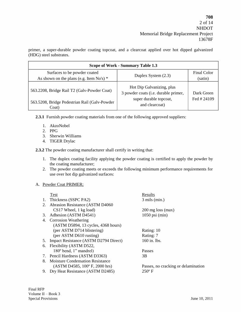
708
2 of 14
NHDOT
Memorial Bridge Replacement Project
13678F
Final RFP
Volume II – Book 3
Special Provisions June 10, 2011
primer, a super-durable powder coating topcoat, and a clearcoat applied over hot dipped galvanized
(HDG) steel substrates.
Scope of Work - Summary Table 1.3
Surfaces to be powder coated
As shown on the plans (e.g. Item No's) * Duplex System (2.3)
Final Color
(satin)
563.2208, Bridge Rail T2 (Galv-Powder Coat)
563.5208, Bridge Pedestrian Rail (Galv-Powder
Coat)
Hot Dip Galvanizing, plus
3 powder coats (i.e. durable primer,
super durable topcoat,
and clearcoat)
Dark Green
Fed # 24109
2.3.1 Furnish powder coating materials from one of the following approved suppliers:
1. AkzoNobel
2. PPG
3. Sherwin Williams
4. TIGER Drylac
2.3.2 The powder coating manufacturer shall certify in writing that:
1. The duplex coating facility applying the powder coating is certified to apply the powder by
the coating manufacturer;
2. The powder coating meets or exceeds the following minimum performance requirements for
use over hot dip galvanized surfaces:
A. Powder Coat PRIMER;
Test Results
1. Thickness (SSPC PA2) 3 mils (min.)
2. Abrasion Resistance (ASTM D4060
CS17 Wheel, 1 kg load) 200 mg loss (max)
3. Adhesion (ASTM D4541) 1050 psi (min)
4. Corrosion Weathering
(ASTM D5894, 13 cycles, 4368 hours)
(per ASTM D714 blistering) Rating: 10
(per ASTM D610 rusting) Rating: 7
5. Impact Resistance (ASTM D2794 Direct) 160 in. lbs.
6. Flexibility (ASTM D522,
180º bend, 1” mandrel) Passes
7. Pencil Hardness (ASTM D3363) 3B
8. Moisture Condensation Resistance
(ASTM D4585, 100º F, 2000 hrs) Passes, no cracking or delamination
9. Dry Heat Resistance (ASTM D2485) 250º F

708
3 of 14
NHDOT
Memorial Bridge Replacement Project
13678F
Final RFP
Volume II – Book 3
Special Provisions June 10, 2011
B. Powder Coat TOPCOAT;
Test Results
1. Thickness (SSPC PA2) 5 mils (min.)
2. Adhesion (ASTM D4541) 1050 psi (min)
3. Flexibility (ASTM D522,
cylindrical mandrel) Passes
4. Pencil Hardness (ASTM D3363) 2H
5. Salt Spray (ASTM B117) 2000 hrs Passes
6. Humidity (ASTM D4585) 100º F, 2000 hrs Passes, no cracking or delamination
7. Impact Resistance (ASTM D2794 Direct) 160 in. lbs.
8. Color Retention (ASTM D2244) 10 years 3∆E (based on inorganic resins)
9. Chalk Resistance (ASTM D4214) none
10. Gloss Retention (ASTM D523) 10 years 45% loss (max)
11. Xenon Arc Test (ASTM D 4798) 400 hrs Passes
2.3.3 Provide each coat of powder coating in sufficiently contrasting color to facilitate proper
coverage and to distinguish it from previously applied coatings. The previous coat shall be hidden by
application of each coat at the specified minimum thickness.
2.3.4 Provide all powder coating materials in sealed, original, containers that are properly marked to
allow verification, with applicable material safety data sheets, application instructions and precautions,
including the manufacturer’s name, type of material, brand name, color, shelf life, purchase order
number, lot and batch numbers, and quantity.
2.3.5 Color. The final color of the painted product shall be (see Table 1.3) (satin) unless specified
otherwise, closely matching the Federal Standard 595B or RAL Color Standard number, as follows:
Description Fed Color # RAL Color Standard
Dark Green 24109
Black 27038
2.3.6 Touchup materials. Repair and touch-up materials shall be supplied by the powder coating
applicator and applied in accordance with the powder coating manufacturer's recommendations.
2.4 EQUIPMENT.
2.4.1 Inspection Equipment. Provide inspection equipment needed to verify the quality of the
entire galvanizing, surface preparation, and powder coating processes, including a Type II dry film
thickness gage that can be calibrated, calibration standards, and a mirror for use by the Department.

708
4 of 14
NHDOT
Memorial Bridge Replacement Project
13678F
Final RFP
Volume II – Book 3
Special Provisions June 10, 2011
DUPLEX COATINGS - POWDER COATING OVER GALVANIZING
3.1 GENERAL
3.1.1 Provide all materials, equipment, and labor necessary to perform the scope of work whether or
not the material or equipment is specifically identified in this Item. Conduct all galvanizing, surface
preparation, powder coating operations, handling, shipment, and installation in a workmanlike manner in
conformance with SSPC-PA1, these requirements, and to the reasonable satisfaction of the Department.
3.1.2 [blank]
3.1.3 Specifications. Perform the work in conformance to the Contract requirements, the reference
standards, and the coating manufacturer's instructions, respectively.
3.1.3.1 Reference Standards. The latest edition of the following standards and regulations in effect
at the time of the Bid form a part of this Specification. A copy of the reference standards applicable to
the work shall be available at the shop facility for use by the Department’s representative.
a. American Society for Testing and Materials (ASTM)
1. ASTM A123, Standard Specification for Zinc (Hot Dip Galvanized) Coatings on Iron
and Steel Products
2. ASTM A153, Standard Specification for Zinc Coating (Hot Dip) on Iron and Steel
Hardware
3. ASTM A385, Standard Practice for Providing High-Quality Zinc Coatings (Hot Dip)
4. ASTM A780, Standard Practice for Repair of Damaged and Uncoated Areas of Hot Dip
Galvanized Coatings
5. ASTM D610, Standard Test Method for Evaluating Degree of Rusting on Painted Steel
Surfaces
6. ASTM D6386, Standard Practice for Preparation of Zinc (Hot Dip Galvanized) Coated
Iron and Steel Product and Hardware Surfaces for Painting.
b. American Association of State Highway & Transportation Officials (AASHTO)
1. AASHTO M111, Zinc (Hot Dip Galvanized) Coatings on Iron and Steel Products
2. AASHTO M232, Zinc Coating (Hot Dip) on Iron and Steel Hardware
c. American Galvanizers Association (AGA)
1. The Inspection of Products Hot Dip Galvanized After Fabrication
2. Powder Coating over Hot Dip Galvanized Steel, Powder Coating Journal, Feb 2004,
Philip Rahrig, AGA Executive Director
3. Powder Coating over Galvanized Steel, Tom Langill, AGA Technical Director
d. Society for Protective Coatings (SSPC)
1. SSPC-SP 1, Solvent Cleaning
2. SSPC-SP 7 / NACE No. 4, Brush Off Blast Cleaning
3. SSPC-PA 1, Shop, Field, and Maintenance Painting
708
5 of 14
NHDOT
Memorial Bridge Replacement Project
13678F
Final RFP
Volume II – Book 3
Special Provisions June 10, 2011
4. SSPC-PA 2, Measurement of Dry Film Thickness with Magnetic Gages
3.1.4 Submittals.
3.1.4.1 Surface Preparation and Powder Coating Plan.
1. Provide a written plan to the Department for applying duplex coatings. Identify the manner
of surface preparation, the powder coat system to be applied, film thickness, cure time
between coats, repair materials and procedures of typical damage and defects in the duplex
coating, and other information needed to successfully apply all coats of the duplex system.
2. Provide material product literature and MSD sheets for the coatings specified, along with test
data indicating conformance to the performance criteria required.
3. Verification samples. Submit six 3-inch by 6-inch samples of the full shop-applied duplex
coating system and color proposed for use for approval to the Department (Bureau of Bridge
Design, Tel. 603-271-2731) a minimum four weeks prior to production coating application.
Samples shall be made of the same or comparable material and thickness as production
pieces.
4. Submit a Certificate of Compliance stating that the requirements of the contract
specifications have been met, in conformance to 106.04.
3.1.4.2 Substitutions or Approved Equals.
1. Substitutions or 'Approved Equals' are defined as meeting the aesthetic, durability, and all
other performance criteria described in this specification, and shall be accompanied by proof
that the Substitution or 'Approved Equal' meets or exceeds these criteria. Approval is the
discretion of the Department. Coatings or processes not matching or exceeding the approved
specified process and aesthetic, durablility, and performance criteria shall be removed and
replaced at the expense of the Design-Builder and all subcontractors that were involved with
the supply of and application of the non-conforming product.
3.1.5 Supplier Coordination.
1. Fabricator-Galvanizer Coordination. Prior to fabrication and final submittal of shop
drawings to the Department, fabricators shall submit shop drawings to the galvanizer for all
metal fabrications to receive shop-applied duplex coatings, to review fabricator's shop
drawings for suitability of materials for galvanizing and coatings, and to coordinate any
required modifications to fabrications required to be performed by the fabricator.
2. The supplier of steel products shall notify the galvanizer if the chemical composition of the
steel to be galvanized exceeds the following limits in order to determine its suitability for
processing: 0.25% carbon, 0.22% silicon, 0.04% phosphorous, and 1.3% manganese.

708
6 of 14
NHDOT
Memorial Bridge Replacement Project
13678F
Final RFP
Volume II – Book 3
Special Provisions June 10, 2011
3.2 HOT DIP GALVANIZING (HDG)
3.2.1 Fabricated products shall meet the requirements of ASTM A385 (for material composition,
cleanliness, drainage vents, etc.) prior to galvanizing, and galvanized surfaces shall meet the
requirements of ASTM D6386 (preparing zinc surfaces for painting), as applicable and as stated herein.
1. Galvanizing: Galvanize materials in accordance with specified standards and this
specification. Galvanizing shall provide an acceptable substrate for applied coatings. The
dry kettle process shall be used to eliminate any flux inclusions on the surface of the
galvanized material.
2. Prior to galvanizing, the steel shall be immersed in a preflux solution (zinc ammonium
chloride). The preflux tank shall be 12-14 Baumé and contain less than 0.4 percent iron. The
wet kettle process is prohibited.
3. Implement the following procedures to provide the appropriate surface for the material to be
galvanized:
a) Utilize and regularly inspect a monitoring recorder to observe any variances in the
galvanizing bath temperature.
b) The pickling tanks shall contain hydrochloric acid with an iron content less than 8 percent
and zinc content less than 3 percent. Titrations shall be taken weekly at a minimum.
c) All chemicals and zinc content will be tested at least once a week to determine
compliance with ASTM standards. All testing will be done using atomic absorption
spectrometry or x-ray fluorescence (XRF) equipment at a lab in the galvanizing plant.
3.2.2 Surface Preparation of Hot Dip Galvanizing (HDG)
1. Prepare all surfaces in conformance to the requirements of this Item, and the approved
Surface Preparation/Powder coating Plan provided under 3.1.4, Submittals.
2. Prior to powder coating, clean and prepare galvanized surfaces as necessary to remove
detrimental contaminants. (See Powder Coating over Galvanized Steel, Feb 2010 Tom
Langill) for cautions regarding cleaning. If applicable apply cleaning materials with clean
lint-free rags or soft bristle brushes frequently changed to prevent reapplying contaminants.
After cleaning, rinse thoroughly with hot water and allow the part to dry completely.
3. Prepare galvanized surfaces with SSPC-SP7, Brush-Off Blast Cleaning, using non-metallic
abrasives at a reduced nozzle pressure as recommended by the equipment manufacturer, or
abraded by approved mechanical means using sanding disks with appropriate abrasive, to
thoroughly roughen the entire surface and produce a dense, consistent, sharp, angular,
uniform anchor pattern with a profile height of 1.0-1.5 mils, exhibiting a uniform gray color
free of any bright, shiny spangles and to an appearance and feel similar to sandpaper.

708
7 of 14
NHDOT
Memorial Bridge Replacement Project
13678F
Final RFP
Volume II – Book 3
Special Provisions June 10, 2011
4. The required thickness of the zinc coating shall be maintained and checked prior to powder
coating. Surface preparation shall be acceptable to the powder coating manufacturer's
requirements. Additional surface preparation or a tie coat may be considered if required by
the powder coating manufacturer and approved by the Department.
5. The substrate surface shall be dry and free from dust, dirt, oil, grease or other contaminants.
3.2.3. Discontinuities. All visually evident detrimental surface imperfections (e.g. flux inclusions,
dross inclusions, oil) that are present on galvanized surfaces shall be cleaned, and any high spots, rough
areas and edges, spikes, and sharp protrusions shall be removed by grinding to produce a smooth surface.
Disbondment (peeling) of galvanizing is not acceptable and the piece shall be regalvanized, or
investigated for extent and severity and a repair solution proposed to the Department for approval before
corrective action is taken.
3.2.4 Surface profiling shall be performed prior to the formation of "white rust" on the galvanized
surface. If any "white rust" is detected by visual means, the galvanizing shall be stripped off and the
steel re-galvanized in conformance with these specifications. "White rust" shall be as defined in the
Inspection of Products Hot Dip Galvanized After Fabrication, Table IV, by the American Galvanizers
Association.
3.2.5 Prior to powder coating galvanized products shall not be nested, stacked or stored with
adjacent surfaces touching but shall be kept separated to be remain dry and permit the circulation of air
between products.
3.3 GALVANIZED STEEL OUTGASSING.
3.3.1 The galvanized parts shall be subjected to a thermal cycle (i.e. outgassing) after surface
profiling and before powder coating application. The thermal cycle should be set at the appropriate
temperature and duration for the thickness of the product recommended by the powder coating
manufacturer.
3.4 POWDER COAT APPLICATION.
3.4.1 Time limits. The first coat of powder coating shall be applied within twelve (12) hours of
galvanizing and within one hour of surface preparation of the galvanized surface and outgassing, at the
galvanizer’s facility, and in a controlled environment meeting applicable atmospheric requirements, as
recommended by the coating manufacturer.
3.4.2 Powder coating application. Pretreatment and powder coating application and curing shall
be performed after galvanizing in conformance with the powder coating manufacturer's recommendations
and shall consist of the following, unless approved otherwise:
1. Verify that the galvanized surface exhibits the specified degree of cleaning immediately prior
to powder coating.

708
8 of 14
NHDOT
Memorial Bridge Replacement Project
13678F
Final RFP
Volume II – Book 3
Special Provisions June 10, 2011
2. The coating and curing facility shall be maintained free of airborne dust and dirt until
coatings are completely cured.
3. The powder coating shall be electostatically applied according to the coating manufacturer's
written specifications, maintaining even coverage on all parts. The powder shall only be
applied when both the ambient temperature is 65º F. or above, and the part surface
temperature is between 60º and 95º F., and is (min.) 5º F. higher than the dew point. Relative
humidity shall be less than 85 percent (max.).
4. After applying the powder, all parts shall be placed in an oven, cured and bonded at the
manufacturer's recommended levels (e.g. approximately 392º F. for 25 minutes). The
Design-Builder shall ensure that a stable transfer exists between the powder application
system and the curing oven to prevent the loss of powder from the parts.
5. The powder coating shall be applied to a minimum dry film thickness of 3 mils primer and 5
mils topcoat, and in a manner that will ensure a uniform coating without holidays, runs, or
detrimental build at edges. A clear coat shall be applied at the manufacturer's recommended
thickness.
6. Each coated part shall be visually inspected. Measure the coating thickness with a thickness
gauge. Any part that does meet the specified coating thickness may be recoated immediately
after lightly abrading (sanding) the surface. Once cured, all parts shall be allowed to cool
sufficiently before further handling.
3.4.3 Surface smoothness - Duplex coatings shall exhibit a smoothness (i.e. rugosity) not greater than
4 rug (16-20 microns of variation) when measured by a profilometer over a 1-inch straight line on the
surface of metal products less than 24 lbs/ linear foot. The profilometer shall be capable of operating in
1 micron increments.
3.4.4 All fasteners shall be galvanized and fastener components visible to view shall be powder
coated. Furnish an application procedure to the Department including which fastener components are to
be powder coated. Coating procedures for fasteners are not restricted to the same-facility (1.2) and 12-
hour maximum window (3.4.1) restrictions, due to the nature of fastener supply.
1. Bolts - Powder coat bolt heads visible to view. Minor overspray is permitted on the threads.
2. Nuts - Powder coat the exterior surfaces of nuts visible to view and mask off interior
surfaces. Nuts not visible to view (e.g. W-beam splice bolts) need not be powder coated.
3. Washers - Powder coat all washers visible to view. Minor overspray is permitted on washer
surfaces that are not required to be powder coated.
3.5 INSPECTION.
3.5.1 Quality Control (QC). The applicator is required to conduct and document quality control
inspection of the cleaning and powder coating operations including at a minimum, measurements of
surface profile, surface cleanliness, dry film coating thickness, and visual inspection for coating defects.
708
9 of 14
NHDOT
Memorial Bridge Replacement Project
13678F
Final RFP
Volume II – Book 3
Special Provisions June 10, 2011
The data shall be recorded in a log maintained at the site and available for the Department’s review
during working hours.
3.5.2 Quality Assurance (QA). The work is subject to QA inspection by the Department.
1. Facilitate QA inspection as required, including proper notification, allowing adequate time
for inspections, and providing access to the work. Furnish, until final acceptance of the
coating system, all equipment, reference documents, and instrumentation needed to inspect
all phases of the work.
2. Measure the thickness of each coat using nondestructive magnetic dry film thickness gages.
Comply with SSPC-PA2 for the calibration and use of gages and the minimum frequency of
thickness measurements. QA Inspectors will not be limited by the frequency of thickness
measurements of PA2 but will take measurements sufficient to assure that proper thickness is
achieved on all surfaces as specified.
3. The presence or activity of Department QA inspections in no way relieves the Design-
Builder of the responsibility to comply with all requirements of this Item, and to provide
adequate inspections of its own to assure compliance with the requirements of this Item.
4. Finished products will be stamped "Approved" only after the loading has been completed and
approved. No material shall be shipped without the prior approval of the Department.
3.6 HANDLING / SHIPPING / INSTALLATION.
3.6.1. Cure. Duplex-coated materials shall not be lifted, placed on supports, or loaded for shipment
until the shop coating has been adequately cured and inspected.
3.6.2. Protective measures. Exercise care in handling shop-coated materials in the shop, and during
storage, shipping, field installation, and subsequent construction to protect the coating from any scraping,
marring, or other damage to the surface finish. Coated material shall be insulated from lifting devices
and from the scraping and rubbing of parts that would damage the coating, by the use of lifting softeners,
nylon slings, padded cables, storage pallets, separators, cushioners, tie-downs, and other approved
supports. Individual parts shall be wrapped or padded with effective protective material (e.g. foam, not
paper or cardboard).
3.6.3. Mechanical damage. Installation operations involve tasks which may damage the finish
coating on some areas of the finished product, such as from driving posts, overlapping sections of rail,
and installing fasteners. The Design-Builder shall exercise reasonable care to minimize damage to the
coating during installation.
3.7 TOUCH-UP AND REPAIRS.
3.7.1 The total repair area shall be less than one quarter of one percent ( 0.25% ) of the area of an
individual member*, or the member shall be rejected and regalvanized and recoated with the duplex
coating. [The repair area definition is comparable to Rust Grade 7 in ASTM D610, Standard Test

708
10 of 14
NHDOT
Memorial Bridge Replacement Project
13678F
Final RFP
Volume II – Book 3
Special Provisions June 10, 2011
Method for Evaluating Degree of Rusting on Painted Steel Surfaces.] [*Note - The areas listed in
Section 3.6.3 subject to mechanical damage during installation shall be repaired as required but are
excluded from the total repair area calculation.]
3.7.2 HDG- Repair damaged galvanizing and bare steel surfaces in accordance with ASTM A780,
Standard Practice for Repair of Damaged Hot Dipped Galvanized Coatings, Annex A2. Thoroughly
clean damaged areas to produce a clean, bare and dry bright metal surface with a roughened profile and
feather into the edges of adjacent undamaged galvanizing. Use a power sanding disk per SSPC-SP3. For
bolts use a thorough hand wire brushing and SP1 cleaning as a minimum.
3.7.3 Apply an approved organic zinc-rich repair paint containing 95 percent (min.) zinc by weight in
the dry film, according to the manufacturer’s recommendations, in two to four coats to a thickness
equivalent to the surrounding galvanizing. Silver paint, brite paint, or aluminum paint is not acceptable.
3.7.4 Powder coating - The repair to the powder coat may be a liquid and brushed on or an aerosol
and sprayed, whichever is appropriate to achieve an aesthetic finish and as long as the coats, cure, and
minimum thickness of the original system are achieved. The Design-Builder shall provide a dry film
thickness gage and check the thickness of the repair areas. Touch-ups shall be such that the repair is not
noticeably visible from a distance of six feet.
1. The field-touch-up of shop-applied finish coatings shall be performed or supervised by
personnel from the duplex coating facility for the warranty to apply.
2. Touch up fasteners in the field after installation, assuming there may be mechanical damage
to nuts during tensioning fasteners.
3. Touch-up repair kits in sufficient quantity and touchup instructions shall be provided to the
field for each type of shop-applied finish. Additional touchup repair kits and instructions
shall be furnished to the Department for use after project acceptance for maintenance repairs.
3.8 FINAL ACCEPTANCE.
Although the Department’s QA Inspector may accept the finished duplex coated fabricated products
before shipment to the jobsite, final acceptance of the duplex coat system by the Department will occur at
the jobsite after installation of the product, and after all coats and repairs have been completed.
3.9 FIVE-YEAR WARRANTY.
Should the duplex system fail within five years after the project has been accepted, the coating shall
be repaired or replaced by the Design-Builder at no cost to the State. The extent and method of repair
must be acceptable to the Department. System failure does not include damage from external agents,
such as scraping from snow removal equipment, vandalism, debris impacts, collisions, etc., or normal
loss of gloss and color. Once the duplex system has been accepted, a failure shall mean any visible
corrosion, blistering, checking, cracking, or delamination (peeling) of the galvanizing or powder coating
resulting from the installation of the product or from the performance of the duplex coating.

708
11 of 14
NHDOT
Memorial Bridge Replacement Project
13678F
Final RFP
Volume II – Book 3
Special Provisions June 10, 2011
POWDER COATING OVER GALVANIZED STEEL
Thomas J. Langill, Ph.D., Technical Director
American Galvanizers Association
Centennial, CO
Abstract: Powder coating over hot dip galvanized steel is an extremely effective corrosion protection
system. However, careful surface preparation techniques need to be used to alleviate potential coating
failures. The age and characteristics of the galvanized coating should be used to determine what type
of surface preparation is needed.
INTRODUCTION
Hot dip galvanized steel parts or assemblies are often required to be painted or powder coated. The
reason for powder coating can be to identify the particular structure, for architectural reasons, to
provide a particular type of protection, or to extend the service life of an existing structure. The
combination of a powder coating system with a hot dip galvanized coating is often referred to as a
“duplex system” (1). When powder coating and galvanized steel are used together, the corrosion
protection is superior to either protection system used alone (2).
The application of a powder coating system onto a hot dip galvanized surface requires careful
surface preparation and a good understanding of both corrosion protection systems. The margin for
error is very small when dealing with newly galvanized steel surface preparation. However, there have
been many examples of powder coating adhesion problems on older or more moderately aged
galvanized steel surfaces, and the most common cause is improper or incomplete surface cleaning and
preparation (3). When the surface is cleaned and prepared correctly the combined powder coating and
galvanized steel corrosion protection system gives extremely long lifetimes (4). If the powder coating
is properly maintained on the galvanized surface there is practically no limit on the life of the structure
in terms of corrosion attack.
The adhesion of powder coating onto galvanized steel becomes a very small problem when the
galvanized coating has weathered for at least a one-year period. The zinc corrosion products form a
very dense, insoluble protective layer that accepts a powder coat readily. A brand new galvanized
coating also experiences few adhesion problems within the first 24 to 48 hours after coating. The
intermediate period from 24 hours to one year can present some challenges to surface preparation but
the corrosion products that are formed on the galvanized surface can be cleaned and the surface can be
successfully powder coated.
GALVANIZED COATING
Hot dip galvanized coatings can be applied in two different ways. The parts can be fed into a liquid
zinc bath in a continuous roller process where the coating characteristics are highly dependent on the
speed of the steel through the liquid zinc bath. The two most common steel products that are hot dip
galvanized using the continuous process are sheet and wire. The objective of the continuous process is

708
12 of 14
NHDOT
Memorial Bridge Replacement Project
13678F
Final RFP
Volume II – Book 3
Special Provisions June 10, 2011
to deposit a zinc coating that is smooth, thin and composed of nearly all zinc bath metal with very little
zinc-iron intermetallic. The coating can be alloyed to form a dull gray intermetallic coating which has
a good surface profile and can be easily powder coated.
The second type of hot dip galvanizing process is often called the “batch” process since individual
steel pieces or assemblies are dipped in a molten zinc bath as individuals or as groups. The coating is
formed by the interdiffusion of zinc and iron. The coating forms four distinct layers or intermetallics.
During the batch hot dip galvanizing process, a number of process variables can affect the coating
thickness. The primary determiner of coating thickness is the steel chemistry, with the most influential
elements being silicon and phosphorous. These two elements promote the interdiffusion of zinc and
iron and cause the hot dip galvanized coating to become thick and filled with intermetallic. The
coating produced when the steel is reactive contains mainly intermetallics of iron and zinc. This
means that the surface will not be bright and shiny, but rather dull gray and slightly rough. This
intermetallic surface makes a very good anchor for powder coating systems. The main concern with
reactive steel galvanized coatings is the thickness of the coating. If the coating is too thick it may
become brittle and will be susceptible to applied stresses that may separate the galvanized coating from
the steel underneath. Knowing the silicon and phosphorous content is very important to producing a
quality galvanized coating.
GALVANIZED STEEL SURFACE PREPARATION
Successful surface preparation is the key to producing adherent powder coatings and realizing the
benefits of a duplex system. There are three basic steps to preparing galvanized surfaces for powder
coating: surface cleaning, surface profiling, and out-gassing of the coating.
Surface Cleaning
When cleaning a galvanized surface prior to powder coating, the goal is to remove any dirt, grease
or oils. At the same time, care must be taken not to remove too much of the galvanized coating.
Alkaline cleaning, ammonia cleaning and solvent cleaning are the most common ways of removing
dirt from a galvanized surface. As some cleaners may react differently with different powder coating
systems, the powder manufacturer should be consulted for specific reaction problems.
Oil, grease and dirt can be removed by using an alkaline solution in the pH range of 11 to 12, but
not greater than 13 as this will damage the zinc coating. Most alkaline cleaning solutions are
nominally 2 to 5 percent sodium compounds with small additions of emulsifying or chelating agents.
The solution can be applied through dipping, spraying or brushing. If brushing is used, apply the
solution with a soft bristle brush, preferably of nylon, definitely not copper or steel bristle brushes. If
dipping or spraying the solution, the temperature range that works best is between 140o and 185
o F.
For newly galvanized steel, a water-based emulsifier can be used to remove contaminants. After
cleaning, thoroughly rinse the surface with hot water and allow the part to dry.
Mineral spirits, turpentine, high flash naphtha, and other typical cleaning solvents can be used to
clean galvanized surfaces provided they are applied with lint-free rags or soft bristle brushes. The rags
and brushes must be changed often to prevent reapplying the contaminants. After cleaning, rinse
thoroughly with hot water and allow the part to dry completely.

708
13 of 14
NHDOT
Memorial Bridge Replacement Project
13678F
Final RFP
Volume II – Book 3
Special Provisions June 10, 2011
A solution of 1 to 2 percent ammonia applied with a soft bristle brush can also be used to clean
galvanized surfaces, although this method is typically reserved for cleaning parts with zinc skimmings
residue. As a piece of steel is removed from the galvanizing kettle, it may pick up particles of oxidized
zinc from the bath surface, otherwise known as zinc skimmings. Skimmings residue must be removed
prior to painting. After cleaning, thoroughly rinse the surface with hot water and allow the part to dry
completely.
Surface Profiling.
In order to provide a good adhesion profile for the powder coating, the galvanized surface must be
flat with no protrusions and slightly roughened to provide an anchor profile. During the removal of the
galvanized article from the zinc bath, the excess zinc runs down the edges of the part and can
sometimes build up at a protrusion or irregular edge. The zinc can also form tears at the edge where it
drains off the part. These high spots and tears must be removed before powder coating as they will be
very difficult to coat. The high spots and tears are usually ground off with hand tools or power
grinders. Care must be taken when performing this operation to insure that the galvanized coating is
not removed below the specified thickness.
In order to roughen the typically smooth galvanized surface after cleaning, an abrasive sweep or
brush blast may be used. Care should be taken to prevent removing too much of the zinc coating.
Particle size for a sweep blast of galvanized steel should range between 200 and 500 microns.
Aluminum/magnesium silicate has been used successfully in the sweep blasting of galvanized steel as
seen in Fig. 1. Organic media such as corn cobs and walnut shells or minerals such as corundum,
limestone and sands with a Mhos hardness of five or less may also be used.
The temperature of the galvanized part when blasting can have a significant affect on the finished
surface profile. Sweep blasting while the galvanized part is still warm from the galvanizing process,
175o to 390
o F, provides an excellent profile for powder coating. Ambient conditions for sweep
blasting are recommended to be less than 50 percent relative humidity and a minimum temperature of
70o F.
The process of sweep blasting should not be confused with the near-white blasting that is used to
clean uncoated steel before applying powder coating systems. This near-white blasting will remove
the galvanized coating and negate the corrosion protection afforded by the zinc. The process of sweep
blasting is best performed by an experienced applicator. If the sweep angle becomes near
perpendicular to the galvanized part, the blasting can quickly remove the protective zinc rather than the
zinc oxide particle on the surface of the coating.
Galvanized Steel Outgassing
The removal of surface entrapped water and solutions is accomplished by a thermal cycle of the hot-
dip galvanized part. Zinc on the surface of the coating can potentially retain air or moisture. Upon
heating during the curing stage of the powder coating process the entrapped air or water can release
causing pinholes of blisters in the powder coating. The thermal cycle should take place after surface
profiling and before the actual powder coating. The thermal cycle should be 25o F or 14
o C above the
curing temperature of the particular powder coating system. This removal of trapped air or water will
significantly lower the potential of pinholes or blisters in the powder coating. For some surface
treatments on the galvanized coating there will be a maximum temperature for the thermal cycle since

708
14 of 14
NHDOT
Memorial Bridge Replacement Project
13678F
Final RFP
Volume II – Book 3
Special Provisions June 10, 2011
the surface treatments may be adversely affected by higher temperatures.
POWDER COATING SELECTION
The proper selection of a powder coating system for a certain engineering need is the province of
the architect and the engineer. There are many options depending on the intended use of the duplex
coated part, the application method and place for the powder coating system, environmental concerns,
and aesthetics of the total system. Many powder coating companies offer good powder coating
systems that are designed to work with galvanized steel. Consult your powder coating manufacturer
for the proper powder coating selection.
DUPLEX SYSTEM PERFORMANCE
When hot dip galvanized steel is powder coated, the duplex system provides a more sophisticated
manner of corrosion protection. The galvanized coating protects the base steel by providing both
cathodic and barrier protection. The powder coating acts as a barrier protection for the hot dip
galvanized coating and significantly reduces the corrosion rate of the zinc. The overall affect on the
base steel is that the duplex system not only provides hot dip galvanized life plus the paint life but also
provides a multiplication factor of 1.5 to 2.3 on the sum of these two lifetimes. This means that a
galvanized coating with a lifetime of 75 years and a powder coating system with a lifetime of 30 years
together would have a lifetime of 157 to 240 years as a Duplex System. The increased lifetime that
can be provided with a combination of powder coating over galvanized steel makes this type of
corrosion protection system very attractive for structures designed to last a long time in aggressive
atmospheres.
SUMMARY
The powder coating of galvanized steel has been a difficult task for many people. The secret of
good powder coating on galvanized steel is the surface preparation of the galvanized surface. If the
surface is newly galvanized, that is less than 48 hours out of the zinc kettle, the surface can be powder
coated after a surface roughening procedure and a thermal outgassing cycle. If the surface of the
galvanized part has been exposed to the environment for more than one year then the surface can be
powder coated after the dirt, grease and oils have been removed and the part has been thermal cycled.
The most difficult time to powder coat galvanized steel is between one day and one year after it has
been galvanized. Following the correct surface preparation procedures can give a satisfactory duplex
system.
REFERENCES
(1) J.F.H. van Eijnsbergen, Duplex Systems, Elsevier Science, New York (1994).
(2) F. Porter, Zinc Handbook, Marcel Dekker, Inc., New York (1991).
(3) J.F. Malone, “Painting Hot Dip Galvanized Steel”, Materials Performance, Vol. 31, No. 5, pp. 3942
(1992).

801
1 of 29
NHDOT
Memorial Bridge Replacement Project
13678F
Final RFP
Volume II – Book 3
Special Provisions June 10, 2011
S P E C I A L P R O V I S I O N
SECTION 801 – BRIDGE MACHINERY
Description
1.1 General
1.1.1 Scope of Work. Sub-sections 7.1, 7.2, 7.3, 7.3, 7.4, 7.5 and 7.6 shall give the
general requirements which apply to all machinery. Section 7.1 also applies to the installation
of electric motors, brakes, limit switches and position transmitters to be mounted with the
machinery but supplied under the Electrical Work. Section 7.1 shall also apply to the
installation of the span and counterweight guides but supplied under Structural Work.
1.1.2 All apparatus for controlling the operation of the span drives and all conduits,
boxes, wiring, cables and other equipment required to extend the necessary circuits from the
control house to the respective components shall be furnished and installed under Division
800 Electrical Pay Items.
1.2 Specifications
The design, workmanship and erection of all machinery components shall meet the applicable
requirements of AASHTO 2007 LRFD Design Specifications for Movable Highway Bridges,
with subsequent interim revisions, hereinafter referred to as the AASHTO Specifications. In
addition, wire ropes shall meet the requirements of AASHTO M 277-06 “Standard
Specification for Wire Rope and Sockets for Movable Bridges”.
1.3 Required Drawings and Data
1.3.1 The Design-Builder shall furnish data and drawings on the mechanical equipment
as listed below and as required elsewhere in these specifications. Data and charts shall be
submitted, or installed on the job, as called for.
1.3.2 The reducer manufacturer shall furnish calculations demonstrating reducers
supplied meet requirements as specified by AASHTO and herein. Calculations shall be
submitted to the Engineer for approval.
1.3.3 The rope manufacturer shall test the required number of rope assemblies of each
type, as assembled with their sockets, to a point of destruction and shall furnish test data to the
801
2 of 29
NHDOT
Memorial Bridge Replacement Project
13678F
Final RFP
Volume II – Book 3
Special Provisions June 10, 2011
engineer for review. Rope assemblies that do not meet the required standards for strength
shall be replaced in accordance with AASHTO 3.2.8 and 3.2.11.
1.4 Working Drawings
1.4.1 Prepare working drawings in accordance with Section E, in addition to meeting the
following requirements:
1. Submit manufacturer's data and/or working drawings for all manufactured and
purchased items of machinery for approval.
2. Coordinate the work of the machinery component manufacturers where
components interface. Review and approve all shop and working drawings
prepared by those Manufacturers for coordination prior to submittal of working
drawings to the Department for approval.
3. Ensure working drawings show all parts and that they are completely detailed
and dimensioned. Do not use reproductions of plans as base sheets for assembly
or erection drawings.
4. List materials and material specifications for each part. Where ASTM or any
other standard specifications are used, give the applicable numbers of such
specifications.
5. Show required finish machining, including grade of finish in accordance with
ANSI B46.1, Surface Texture, and dimensional tolerances and allowances for
specific fits in accordance with ANSI B4.1, Preferred Limits and Fits for
Cylindrical Parts.
6. Ensure working drawings are prepared according to the provisions of the general
requirements of the Standard Specifications as supplemented and amended
herein and to the special requirements specified hereinafter. Also, ensure all
drawings are prepared according to NHDOT Standards, latest revision.
7. Submittals for each manufactured item must be manufacturer's descriptive
literature, drawings, diagrams, performance and characteristic curves, and
catalog cuts, and must include the manufacturer's name, trade name, catalog
model or number, nameplate data, size, certified layout dimensions, capacity,
specification reference, including ASTM, ANSI, Federal Military Specification
and any other applicable references, and all other information necessary to
establish Contract compliance.
8. Ensure the fits and finishes used are according to any other requirements given
hereinafter in this General Specification.
9. Show all external dimensions and clearances necessary for installation and
operation of all new machinery components on working drawings.
10. Furnish complete assembly drawings or diagrams for all assemblies and parts,
showing each part contained therein and the manufacturer's part number
assigned to each part. Ensure the drawings or diagrams are sufficient to enable
complete disassembly and reassembly of the assemblies covered. In the event
that any part is modified in any manner from the way it is described or delivered

801
3 of 29
NHDOT
Memorial Bridge Replacement Project
13678F
Final RFP
Volume II – Book 3
Special Provisions June 10, 2011
by its original manufacturer, furnish a drawing which details each modification
and assign a unique part number to assure the furnishing of replacement parts
modified in similar fashion.
11. Furnish certified prints of each manufactured assembly. Certified prints are
manufacturer's drawings of proprietary products on which the manufacturer or
supplier states mounting dimensions, ratios, speeds, ratings, and any other
correctness for use on this specific project. In addition to identifying and
describing each part, ensure the certified prints show:
1. Dimensions of all principal parts comprising the assembly.
2. Certified external dimensions affecting clearances and required for
installation.
3. Capacity and normal operating ratings.
4. Recommended lubrication, including location, lubrication fittings and
provisions for adding, draining and checking the level of lubricants.
5. Inspection openings, seals and vents.
6. Details or description of all fasteners required to mount the assembly.
7. Gross weight.
8. Provide certified prints signed by an officer of the manufacturing
company.
12. Show in outline on working drawings, all proprietary items and also indicate the
method and sequence employed in assembly of bridge machinery and
installation of necessary utilities support and service facilities. In addition to
identifying and describing each internal part, the assembly drawings of each
item must contain dimensions of all principal elements within the item; certified
external dimensions affecting interfaces or installations; gross weight capacity
and normal operating ratings; method and recommended type of lubrication,
including location and type of fittings and provisions for adding, draining, and
checking the level of each lubricant employed; inspection openings, seals, and
vents; and details of all fasteners used to mount the equipment to its foundation.
13. Create complete shop bills of materials for all machinery parts. If the bills are
not shown on the working drawings, furnish prints of the bills in the same
manner as specified for the working drawings.
14. State the weight of each piece of machinery on the working drawing upon which
it is detailed or billed.
15. Furnish complete assembly and erection drawings. These drawings must give
part numbers, match marks, and essential dimensions for locating each part or
assembled unit with respect to the bridge structure or foundation.
16. Clearly show and detail all marks or indentations of any type. In general, avoid
die-stamping or scoring. Detail all components and assemblies separately to
assure correct fabrication, assembly, and erection. Do not use mirror image or
opposite hand erection drawings.

801
4 of 29
NHDOT
Memorial Bridge Replacement Project
13678F
Final RFP
Volume II – Book 3
Special Provisions June 10, 2011
17. Provide a suitable title on each working drawing such that it describes the parts
detailed thereon and indicate who makes the shop inspection.
18. Submit proof of conformance where equipment or materials are specified
conform to requirements of the standards of an organization, such as American
Society for Mechanical Engineers (ASME), Underwriters Laboratories (UL),
American Gas Association (AGA), and American Refrigeration Institute (ARI),
that use a label or listing as method of indicating compliance. The label or
listing of the specified organization is acceptable evidence. In lieu of the label
or listing, submit a certificate from an independent testing organization
adequately equipped and competent to perform such services and approved by
the Contracting Officer, stating that the item has been tested in accordance with
the specified organization's test methods and that the item conforms to the
specified organization's standard or code.
19. As used herein, certified test reports refer to reports of tests conducted on
previously manufactured materials or equipment identical to that proposed for
use.
20. As used herein, factory tests refer to tests required to be performed on the actual
materials or equipment proposed for use. Submit test results according to the
provisions of this Contract for laboratory test results.
21. Prepare a list of all machinery items that require lubrication and their rec-
ommended cycle for lubrication. Prior to the start up and testing of the
machinery, provide the Department a list containing the types of lubricant used
and the date it was lubricated.
22. Prepare and submit lubrication charts prepared as working drawings. After final
approval, furnish one lubrication chart for each machinery room. Lubrication
charts are to be 17” x 24” and framed with durable translucent plastic cover, to
be mounted in location approved by the Department. Lubrication charts are to
include all machinery items clearly identified that require lubrication, their rec-
ommended cycle for lubrication, type of lubricant, and method of application.
23. Submit any departures from the Contract Drawings or these Specifications for
approval by the Department. Provide details of such departures and the reasons
as soon as practicable in writing. Make no departures from Contract drawings
without approval by the Department. Any departure from the Contract
documents that are made without this approval, risk being required to remove
the equipment, correct any modifications, and replace with approved equipment,
components, etc., at no additional cost to the owner..
24. It is the Design-Builder's responsibility to manufacture and install suitable
functioning machinery. Review and approval of working drawings by the
Department does not relieve the Design-Builder of this responsibility.
1.5 Quality Assurance
1.5.1 Qualifications, Personnel and Facilities

801
5 of 29
NHDOT
Memorial Bridge Replacement Project
13678F
Final RFP
Volume II – Book 3
Special Provisions June 10, 2011
1. Use only products produced by manufacturers regularly engaged in the
manufacture of the specified products.
2. Ensure adequate numbers of skilled, trained, and experienced
mechanics and millwrights are thoroughly familiar with the
requirements and methods specified for the proper execution of the
specified work for the fabrication, installation, cleaning, aligning,
testing and all other work required. Provide supervisory personnel with
a minimum of 2 movable bridge jobs as previous experience in the
installation of bridge machinery.
3. Provide adequate plant and all necessary tools and instruments required
for the proper performance of the personnel engaged in the execution of
the specified work.
1.5.2 2. Codes and Standards
Work under machinery pay items must comply with, but not be limited to, all
applicable requirements of the following codes and standards and their
abbreviations used in this Specification are as shown:
1. American Association of State Highway and Transportation Officials AASHTO
2. American Gear Manufacturers Association AGMA
3. American Iron and Steel Institute AISI
4. American National Standards Institute ANSI
5. American Society for Testing and Materials ASTM
6. American Welding Society AWS
7. Anti-Friction Bearing Manufacturers Association AFBMA
8. National Lubricating Grease Institute NLGI
9. Society of Automotive Engineers SAE
10. Steel Structures Painting Council SSPC
11. New Hampshire Standard Specifications -
1.5.3 Ensure the work meets the requirements of all other codes and standards as
specified elsewhere in these Specifications. Where codes and standards are mentioned for
any pay item, it is intended to call particular attention to them; it is not intended that any other
codes and standards are not applicable if not mentioned.
1.5.4 Rules, Regulations and Ordinances
1. Work must comply with all applicable Federal, State and local rules,
regulations, and ordinances.
2. In the event of a conflict between these Specifications and the above-
mentioned codes, standards, rules, regulations, and ordinances, the
most stringent requirement applies.
1.5.5 Measurements and Verification

801
6 of 29
NHDOT
Memorial Bridge Replacement Project
13678F
Final RFP
Volume II – Book 3
Special Provisions June 10, 2011
1. Dimensions indicated on the Contract Drawings are nominal and are
intended for guidance only. Note all variations from the nominal
dimensions on the Contract Drawings on the shop drawings.
1.5.6 Substitutions
1. The terms "approved equal", "of equal quality" and "or equal" which
appear on the Contract Drawings and in these Specifications are
intended to allow the Design-Builder to substitute other manufacturers
and model numbers of products of equal quality and rating for those
specified.
2. Prior to the ordering of any substitute product, obtain in writing the
Department’s approval of the equivalence the substitute product. The
acceptance of the substitute products is at the sole discretion of the
Department who will establish the basis for equivalence and will
review the quality of the materials and products described in detail on
the submitted working drawings and product data.
3. The Department will review and stamp substitute material either
"Approved" or "Revise and Resubmit". Upon return of a working
drawing showing rejection, resubmit the working drawing showing the
specified product. Rejection shall not in any way result in any extra
cost.
4. Approval by the Department of any substitute products does not relieve
the Design-Builder of responsibility for the proper operation,
performance, or functioning of that product.
5. Where a particular product is specified by a manufacturer's name and
catalog or part number in this Specification or on the Contract
Drawings, it is specified to establish quality, configuration, and
arrangement of parts. An equivalent products made by another
manufacturer may be substituted for the specified product subject to the
approval of the Department; however, all necessary changes required
by the substitution to related machinery, structural, architectural and
electrical parts, will be made at no additional cost to the owner.
6. Submit any departures from the Contract Drawings or these
Specifications for approval by the Department. Provide details of such
departures and the reasons as soon as practicable. Make no departures
without approval by the Department. Any departure from the Contract
documents that are made without this approval, risk being required to
remove the equipment, correct any modifications, and replace with
approved equipment, components, etc., at no additional cost to the
owner.
1.5.7 Shop Assembly

801
7 of 29
NHDOT
Memorial Bridge Replacement Project
13678F
Final RFP
Volume II – Book 3
Special Provisions June 10, 2011
1. Shop assembly of machinery is covered under Section 7.2 – “Span
Operating Machinery”.
1.5.8 Specialized Machinery Components Field Installation, Adjustment, and Inspection
1. Furnish manufacturers’ service personnel skilled in these specialties
during the installation, adjustment, and alignment of all specialized
machinery components. Ensure service personnel are properly
equipped with all necessary instruments to assure that related
components are within acceptable tolerances and to make all necessary
adjustments for attaining the specified ratings.
1.5.9 Inspection and Testing
1. Provide no less than 10 working days notice to the Department of the
beginning of work at foundries, forge, and machine shops so that
inspection may be provided. No materials must be cast, forged, or
machined before the Department has been notified where the orders
have been placed.
2. Furnish all facilities for the inspection of material and workmanship in
the foundries, forge, and machine shops and allow the Inspector
designated by the Department free access to necessary parts of the
premises. Work done while the Inspector has been refused access or
presented in a manner that prevents adequate inspection will
automatically be rejected.
3. The Department’s Inspector will reject materials or workmanship that
does not fulfill the requirements of these Specifications.
4. Inspection at the foundries, forge, and machine shops is intended as a
means of facilitating the work and responsibility in regard to imperfect
material or workmanship and to avoid the necessity of replacing
defective materials or workmanship which are delivered to the job site.
5. Furnish the Department with a copy of all orders covering work
performed by subcontractors or suppliers.
6. Furnish, without additional charge, test specimens as required, and all
labor, testing machines, tools, and equipment necessary to prepare the
specimens and to make the physical tests and chemical analyses
required by material specifications. Furnish a copy of all test reports
and chemical analyses to the Department.
7. Engineer acceptance is not a bar to their subsequent rejection if
materials and parts are later found defective. Replace or make
acceptable all rejected material and workmanship at no additional cost
to the State – NHDOT.
1.5.10 Defective Materials and Workmanship
801
8 of 29
NHDOT
Memorial Bridge Replacement Project
13678F
Final RFP
Volume II – Book 3
Special Provisions June 10, 2011
1. Remove all machinery rejected during inspection and testing and
replace without additional cost.
2. Make no claims on delays resulting from the rejection of material,
equipment or work.
3. At no additional cost, correct all defects found during the guarantee
period resulting from faulty material, components, workmanship, or
installation. The NHDOT reserves the right to make necessary
correction with its own forces and charge the resulting costs to the
Design-Builder.
1.5.11 Training
1. Provide 3 days of instruction to NHDOT Maintenance personnel. The
instruction will include but not be limited to the following with respect
to all machinery components.
1. Brake adjustment and operation
2. Checking, adding, and purging lubricants to newly installed
components
3. Auxiliary drive operation
4. Instrument drive and limit switch adjustments
1.6 Delivery and Storage and Protection for Shipment.
A. Machinery parts shall be cleaned of dirt, chips, grit, and all other injurious
materials prior to shipping and shall be given a coat of corrosion-inhibiting
preservative.
B. Finished metal surfaces and unpainted metal surfaces that would be damaged
by corrosion shall be coated as soon as practicable after finishing with a rust-
inhibiting preservative. Excepting unfinished metal surfaces inside of gear
reducers, this coating shall be removed from operation and from all surfaces
prior to painting after erection.
C. Any interface between stainless steel or aluminum and Structural Steel shall
receive an Engineer approval coat of zinc-chromate primer prior to assembly.
D. Shims shall be coated prior to shipment with a rust-inhibiting preservative, and
before erection, this coating shall be removed from the shims that are used.
E. Machinery parts shall be completely protected from weather, dirt, and all other
injurious conditions during manufacture, shipment, and storage.

801
9 of 29
NHDOT
Memorial Bridge Replacement Project
13678F
Final RFP
Volume II – Book 3
Special Provisions June 10, 2011
F. Shaft journals that are shipped disassembled from their bearings shall be
protected during shipment and before erection by a packing of oil-soaked
waste secured in place by burlap and covered with heavy metal thimbles or
heavy timber lagging securely attached. Every precaution shall be taken to
ensure that the bearing surfaces are not damaged and that all parts arrive at
their destination in satisfactory condition.
G. Assembled units shall be mounted on skids or otherwise crated for protection
during handling and shipment.
2. Packaging and Delivery of Spare Parts. Spare parts shall be
protected for shipment and prolonged storage by coating, wrapping, and
boxing.
All spare parts shall be durably tagged or marked with a clear identification
showing the designation used on the approved shop drawing.
Boxes for spare parts shall be clearly marked on the outside to show their
contents. Spare parts shall be delivered to a location designated by the
NHDOT.
3. Guarantee and Warranties. Manufacturer's warranties or
guarantees on equipment, materials or products purchased for use on the
Contract which are consistent with those provided as customary trade practice,
shall be obtained by the Design-Builder and, upon acceptance of the Contract,
the Design-Builder shall assign to the New Hampshire Department of
Transportation, all manufacturer's warranties or guarantees on all such
equipment, material or products furnished for or installed as part of the Work.
The Design-Builder shall warrant the satisfactory in-service operation of the mechanical
equipment, material, products, and related components. This warranty shall extend for a
period of one year following the date of final acceptance of the Project.

801
10 of 29
NHDOT
Memorial Bridge Replacement Project
13678F
Final RFP
Volume II – Book 3
Special Provisions June 10, 2011
1.7 Components Having Extensive Delivery Periods
The Design-Builder’s attention is called to the fact that certain mechanical components may
normally require long delivery times that could affect the schedule if not proactively addressed.
These include but may not be limited to the tower sheave assemblies, the operating drum
assemblies, and the speed reducers for operating machinery. The Design-Builder shall obtain
all delivery times necessary to meet the schedule; shall expedite the production, submission and
resubmission of shop and working drawings for these items, including assembly drawings; and
shall expedite the manufacture of these items so that the schedule does not slip.
Materials
2.1 General
2.1.1 The materials shall meet the minimum requirements specified herein. Materials
and equipment shall be essentially the standard catalogued products of manufacturers
regularly engaged in production of such materials or equipment and shall be manufacturer's
latest standard design that complies with the specification requirements. Materials and equip-
ment shall essentially duplicate items that have been in satisfactory commercial or industrial
use at least two years prior to bid opening. Where two units of the same class of equipment
are required, these units shall be products of a single manufacturer; however, the component
parts of the system need not be the products of the same manufacturer. Each major
component of equipment shall have the manufacturer's name and address and the model and
serial number on a nameplate, securely affixed in a conspicuous place. The name plate of the
distributing agent will not be acceptable
2.1.2 All equipment and materials furnished under the items specified herein shall be
brand-new. All new equipment, materials and workmanship shall be first class in every
particular, and shall be manufactured and installed to the satisfaction of the Engineer and be in
accordance with the recommendations of the manufacturer of the material being installed,
printed copies of these recommendations shall be furnished to the Engineer prior to
installation.
2.1.3 Portions or all of certain recognized industry or association standards or
specifications referred to herein as being a requirement of these Special Provisions shall be
considered as binding as though reproduced in full herein unless supplemented and/or
modified by more stringent requirements of the Contract Documents. Unless otherwise stated
the reference standard or specification which is current as of the date of issuance of these
Special Provisions.

801
11 of 29
NHDOT
Memorial Bridge Replacement Project
13678F
Final RFP
Volume II – Book 3
Special Provisions June 10, 2011
2.2 Steel Castings
2.2.1 Steel castings shall conform to the requirements of ASTM A27 and/or ASTM
A148.
2.2.2 All steel castings shall be fully annealed. Castings shall be true to pattern in form
and dimensions, free from pouring faults, sponginess, cracks, blow holes, and other defects in
positions affecting their strength and value for the service intended. All castings shall be
sandblasted or otherwise effectively cleaned of scale and sand, to present a smooth, clean, and
uniform surface. All unfinished edges of castings shall be neatly cast with rounded corners,
and all inside angles shall have ample fillets. All surfaces requiring finish shall have adequate
material allowance for machining to finish dimensions. Machined bosses shall be provided
on cast steel machinery parts to give proper seats for bolt heads and nuts.
2.2.3 Blow holes appearing upon finished castings shall be so located that a straight line
laid in any direction will not cut a total length of cavity greater than one inch in any one foot,
nor shall any single blow hole exceed one inch in any dimension or have an area greater than
one-half square inch. Blow holes shall not have a depth injuriously affecting the strength of
the casting. Minor defects, which do not impair the strength may, with the approval of the
Engineer, be welded by an approved process and be inspected by magnetic particle
examination. The defects shall be removed to solid metal by chipping, drilling, or other
satisfactory method, and, after welding, the castings shall be annealed, if required by the
Engineer. Castings which have been welded without the Engineer's permission will be
rejected.
2.2.4 All castings that have solid sections 100 millimeters thick or greater shall be
ultrasonically tested in accordance with ASTM A609, Method A, Quality Level 3. Castings
that do not pass this test may be rejected. Test results, whether positive or negative, shall be
submitted to the Engineer.
2.2.5 Carbon Steel and Alloy Steel Forgings shall meet the requirements of AASHTO
Specification M102 (ASTM A668M) unless as otherwise approved by the Department.
2.3 Steel Castings and Forgings
2.3.1 All necessary precautions shall be taken to fabricate the castings free of cracks,
cold shuts, shrink holes, blowholes, and porosity.

801
12 of 29
NHDOT
Memorial Bridge Replacement Project
13678F
Final RFP
Volume II – Book 3
Special Provisions June 10, 2011
2.3.2 All castings shall be cleaned free of loose scale and sand; all fins, seams, gates,
risers, and other irregularities shall be removed. All unfinished edges of castings shall be
neatly cast with rounded corners, and all inside angles shall have ample fillets.
2.3.3 All castings shall be ultrasonically tested in accordance with ASTM A609, Method
A, Quality Level 3. Castings that do not pass this test may be rejected. Test results, whether
positive or negative, shall be submitted to the Engineer. Test records meeting Quality Level 4
may be considered for weld repaired, provided the fabricator submits a procedure to the
Engineer for review and approval. All repair procedures shall include a means to qualify the
repair. Test records meeting Quality Level 5 or higher shall be cause for rejection, and not be
allowed for weld repair. Rejection shall result in the Design-Builder providing a new casting
meeting the acceptance criteria.
2.3.4 All castings shall be visually inspected in accordance with ASTM A 802, Level II.
Castings that do not pass this test may be rejected. Test results, whether positive or negative,
shall be submitted to the Engineer. Test records meeting Level III may be considered for weld
repair, provided the fabricator submits a procedure to the Engineer for review and approval.
All repair procedures shall include a means to qualify the repair.
2.3.5 All castings shall be magnetic particle examined in accordance with ASTM E125.
The following level of discontinuities will be acceptable.
Type I Cracks/Hot Tears ¼” max
Type II Shrink Degree 3
Type III Inclusions Degree 3
Type IV Chaplets Degree 2
Type V Porosity Degree 1
2.3.6 Test results, whether positive or negative, shall be submitted to the Engineer. All
surface discontinuities may be considered for weld repaired, provided the fabricator submits a
procedure to the Engineer for review and approval. All repair procedures shall include a
means to qualify the repair.
2.3.7 All proposed weld repairs shall be performed prior to all heat treatment so that no
weld repairs will be necessary after machining. In addition, all surface defects removed by
machining shall be performed prior to heat treatment.
2.3.8 Carbon Steel and Alloy Steel Forgings shall meet the requirements of AASHTO
Specification M102 (ASTM A668) unless as otherwise approved by the owner. The main
pinion shafts shall conform to the requirements of ASTM A291. Other shafts and trunnions
shall conform to the requirements of ASTM A668.

801
13 of 29
NHDOT
Memorial Bridge Replacement Project
13678F
Final RFP
Volume II – Book 3
Special Provisions June 10, 2011
2.4 Bearings and Bushings
2.4.1 Anti-friction bearings shall be selected for B-10 life of 40,000 hours.
2.4.2 Pillow block and flange-mounted roller bearings shall be, adapter mounting, self-
aligning expansion and non-expansion types as called for on the drawings. Housings shall be
cast steel and capable of withstanding the design radial load in any direction, including uplift.
Bases shall be cast without mounting holes. Undersized mounting holes shall be drilled from
the solid in the shop to ensure perpendicularity and location. Seals shall retain the lubricant
and exclude water and debris. Cap bolts on pillow blocks shall be high-strength steel. The
cap and cap bolts shall be capable of resisting the rated bearing load as an uplift force.
2.4.3 All grease-lubricated bronze bushings 8 inch diameter or less shall have grease
grooves cut in a spiral pattern for the full length of the bearing. All grease grooves shall be
machine-cut and smooth. The corners of all grooves shall be rounded to a radius of not more
than half the width of the groove. The grooves shall be 3/8 inch wide at the bearing surface
and be rounded to a 1/8 inch radius.
2.4.4 Laminated bearing liners shall be surface-bonded, laminated brass or bronze shim
stock. The laminations shall be peelable by knife for reductions of 0.003 inch in thickness of
the laminated stack. Laminated shims shall be as manufactured by one of the following
companies, or approved equal.
1. Ohio Gasket & Shim Company, Akron, OH
2. Metallo Gasket Co., New Brunswick, NJ
3. Allinabal, Milford, CT
4. Spirol International Corp., Danielson, CT
5. Laminated Shim Company, Orange, CA
2.4.5 Pillow blocks shall be as manufactured by one of the following companies, or
approved equal:
1. The Timken Company, Torrington, CT
2. Meither Bearing Products, Inc., Odessa, TX
3. SKF Bearing Industries, Inc., King of Prussia, PA
2.5 Open Gears
2.5.1 All open gears shall have 20-degree full-depth involute cut teeth with tooth
proportions in accordance with the ISO (International Organization for Standardization)
Standard No. 53 and conform to the requirements of AASHTO Specifications and the
requirements for accuracy of the AGMA Standard 2001-D04, Fundamental Rating Factors

801
14 of 29
NHDOT
Memorial Bridge Replacement Project
13678F
Final RFP
Volume II – Book 3
Special Provisions June 10, 2011
and Calculation Methods for Involute Spur and Helical Gear Teeth, except as otherwise
provided herein. The open gears shall conform to AGMA Quality No. 7 or higher. The
AGMA quality number shall be stated on the applicable shop drawings.
2.5.2 The teeth of all gears shall be cut from solid rims or blanks. The teeth shall be
provided with the appropriate root radius to limit stress concentration, but still allow for
proper operation. The sides and peripheries of all gears and pinions shall be finished and the
pitch circle shall be scribed on both sides not less than 0.020 inch deep with a V-pointed tool.
The working surfaces of all gear teeth shall be true to the proper outline, accurately spaced on
the true pitch circle, exceptionally smooth and free from planning or milling cutter ridges.
Cutter burrs shall be removed from all edges of the teeth and the top edges of all teeth shall be
rounded to a 1/32 inch radius.
2.6 Speed Reducers
2.6.1 Speed reducers with minimum requirements shall conform to the requirements of
AASHTO and shall also conform to AGMA Product Standard 6010-F97, Standard for Spur,
Helical, Herringbone, and Bevel Enclosed Drives, and shall carry the AGMA symbol on the
nameplate. In addition, no component or element of the speed reducer shall be stressed to
more than 75 percent of the material yield strength at 300 percent of the required nameplate
output torque rating.
2.6.2 Gears and shafts shall be heat-treated alloy steel suitable for the intended service.
Casehardened gears shall not be used in speed reducers of the span drive. Gearing in enclosed
reducers shall conform to AGMA Quality No. 8 or higher.
2.6.3 Housings shall be of cast steel or welded plate construction. Inspection covers
shall be provided to permit inspection of the gearing inside.
2.6.4 Provisions shall be made for filling, draining, and ventilating the housings; and a
sight gauge shall be mounted on each unit to read the recommended lubricant level.
Ventilation opening shall come equipped with a moisture (hygroscopic) and particle filtration
unit.
2.6.5 The drain provisions shall include a shut-off valve between a drain pipe cap and
each reducer. A hose bib or other device suitable for connecting a 1” drain hose shall be
provided for the reducer.

801
15 of 29
NHDOT
Memorial Bridge Replacement Project
13678F
Final RFP
Volume II – Book 3
Special Provisions June 10, 2011
2.6.6 A drain hose shall be provided for use when oil must be drained from the reducer.
The hose shall be a minimum of 50 feet long. The hose shall be provided with a storage reel
and shall be permanently stored where directed by the Engineer.
2.6.7 The inside of the housings shall be sandblast cleaned prior to assembly and be
protected from rusting.
2.6.8 Speed reducers shall be provided with continuous oil bath lubrication. The
lubricant level shall be such that all shaft bearings are submerged or to such higher level as
recommended by the reducer manufacturer. The reducer shall be provided with effective
seals to retain the lubricant.
2.6.9 The reducers shall be rated for a service factor of 1.0 at 150% horsepower rating of
the main motors. The AASHTO requirements for peak or breakdown torque shall be
construed to mean that the stress levels may be a maximum of 50 percent higher than normal.
Additional testing requirements are included in this Specification under Construction Details.
2.7 Shafts
2.7.1 All shafts and pins shall be accurately finished, round, smooth and straight and,
when turned to different diameters, shall have rounded fillets at the shoulders. Each shaft or
pin having a uniform diameter of 8 inches or more and each shaft or pin having several
diameters, of which the smallest is 8 inches or more, shall be bored lengthwise through the
center to a diameter approximately one-fifth the smallest body diameter.
2.7.2 All shafts shall conform to tolerances in ASTM A29 unless otherwise indicated.
Turned, ground and polished shafting straightness tolerances shall be 0.002 inches per foot for
shafts up to and including 1-½ inches in diameter and 0.005 inches per foot for shafts over 1-
½ inches in diameter.
2.7.3 Each end of all shafts, when finished to the required lengths shall have a 60-
degree lathe center, with clearance hole, at the exact center of the shaft. Shafts that are bored
with an inspection hole shall have the ends prepared for the attachment of a centering device
equivalent to the lathe center. All such devices shall be furnished as part of the work.

801
16 of 29
NHDOT
Memorial Bridge Replacement Project
13678F
Final RFP
Volume II – Book 3
Special Provisions June 10, 2011
2.7.4 Where shown on the drawings, stepped shafts shall have fillets blended in
smoothly to adjacent surfaces without tool marks or scratches. Unless otherwise required
herein or on the drawings to have a finer finish, the surfaces shall have an ANSI maximum
roughness of 63 micro inches. Fatigue calculations for all stepped shafting, including
counterweight trunnion shafts and main pinion shafts, shall be performed.
2.7.5 All cold-finished shafting shall be steel of the type and grade shown on the
drawings and shall be tested for its mechanical properties, and a test certificate shall be
furnished to the Engineer. Each cold-finished shaft shall be free from camber and shall run
without vibration, noise, or chatter at all speeds up to and including the maximum rated speed.
2.7.6 All hubs mounted on the ends of cold-finished shafts shall have the fit specified
herein or on the drawings. To obtain the required fit between hub and shaft, the Design-
Builder shall furnish the cold-finished shaft 1/16 inch larger than the nominal diameter
specified and shall turn the ends to the required dimension for the hub. The Design-Builder
may, at his option, furnish any cold-finished shaft of one diameter end to end; but such a shaft
shall have tolerances selected from the normal manufacturing range to provide the specified
fit. The selected tolerances shall be shown on the shop drawings.
2.8 Couplings
2.8.1 Couplings shall include grid type or gear type.
2.8.2 All couplings and shaft fits and finishes shall meet the requirements of AASHTO
for hubs on shafts. Couplings shall, in general, be finish-bored and have keyways cut by the
Coupling Manufacturer to dimensions and tolerances established on the working drawings
and then shipped to the manufacturers of the various components for shop installation on the
shafts.
2.8.3 The couplings shall have provisions for lubricating all contact surfaces and the
housings shall be oil-tight under all operating conditions.
2.9 Fasteners

801
17 of 29
NHDOT
Memorial Bridge Replacement Project
13678F
Final RFP
Volume II – Book 3
Special Provisions June 10, 2011
2.9.1 Unfinished bolts shall conform to the requirements of ASTM A325, Standard
Specification for Structural Bolts, Steel, Heat Treated, 120/105ksi Minimum Tensile Strength.
Turned bolts shall conform to ASTM A449, Standard Specification for Hex Cap Screws,
Bolts and Studs, Steel, Heat Treated, 120/105/90 ksi Minimum Tensile Strength, General Use.
Bolts shall have single self-locking nuts or double nuts. Beveled washers shall be used where
bearing faces have a slope of more than 1:20 with respect to a plane normal to the bolt axis.
Except as otherwise provided in this article, bolted construction shall conform to applicable
specifications.
2.9.2 Unfinished Bolts
Unfinished bolts shall be furnished unless other types are specified. The bolts shall be of such
length that they will extend entirely through their nuts, but not more than 1/4 inch beyond
them. Bolts shall conform to the requirements of Section 2.6.18 Fasteners and Section 3.3.15
Bolt Holes and Bolts, of the AASHTO Specifications.
2.9.3 Turned Bolts
The surface of the body of turned bolts shall have a surface finish roughness height of 63
microinches. Heads and nuts shall be hexagonal with standard dimensions for bolts of the
nominal size specified or the next larger nominal size. Diameter of shanks shall be 1/16”
greater than the threaded portion of the bolt. Holes for turned bolts shall be carefully reamed
with bolts furnished to provide for a LC6 fit. Threads shall be entirely outside of the holes.
An extra thick washer shall be provided under the nut. Turned bolts shall conform to the
requirements of Section 2.6.18 Fasteners and Section 3.3.15 Bolt Holes and Bolts, of the
AASHTO Specifications.
2.9.4 High Strength Bolts
Where noted on the Drawings, bolts shall be ASTM A 325 Type 1 or ASTM A449 with
heavy hex suitable nuts and washers. Where connecting galvanized parts galvanized bolts
shall be used. SAE J429 Grade 5 bolts will be considered as an equivalent product for
interconnecting machinery components. Rolled or pressed threads will not be accepted for
galvanized bolts. Galvanizing, where required, shall conform to the requirements of ASTM A
153 or B 695.
2.10 Keys and Keyways
Keys and keyways shall be provided between open gears, couplings, clutches and their
respective shafts. Keys and keyways shall conform to the dimensions and tolerances for
801
18 of 29
NHDOT
Memorial Bridge Replacement Project
13678F
Final RFP
Volume II – Book 3
Special Provisions June 10, 2011
square and flat keys of ANSI B17.1. All keys shall be effectively held in place, preferably by
setting them into closed-end keyways milled into the shaft. The ends of all such keys shall be
rounded to a half circle equal to the width of the key. Subject to the Engineers approval, keys
that are not set into the closed-end keyways shall be held by safety set screws, or other
effective means. Keyways shall not extend into any bearing.
2.11 Shims
2.11.1 All machinery shims required for leveling and alignment of equipment shall be
neatly trimmed to the dimensions of the assembled parts and drilled for all bolts that pass
through the shims. Holes for bolts shall be oversized by 1/16-inch. In general, sufficient
thickness shall be furnished to secure 1/64-inch variations of the shim allowance plus one
shim equal to the full allowance. Shimming of equipment shall be performed with the least
amount of shims needed to fill space. No more than five (5) shims shall be used unless
approved by the Engineer. Shims shall conform to the requirements of ASTM A709, Grade
36, except that thickness less than ¼-inch shall be stainless steel. Corrosion resistant
precision thickness shims will be permitted if desired by the Design-Builder.
2.11.2 Shims with open side or U-shaped holes for bolts will not be permitted. No shims
shall have less than two holes for bolts.
2.11.3 The use of peelable laminated shims with solder or resin bonding will be permitted
as previously specified. Plastic or other non-metallic shims will not be permitted.
2.12 Structural Steel
2.12.1 Structural steel for machinery base supports and counterweight sheave covers shall
conform to the requirements of the Standard Specification, ASTM A709, Grade 50. Steel
components of manufactured items shall conform to the materials recommended by the
manufacturer.
2.12.2 The Design-Builder shall provide suitable supports that are structurally adequate.
The material thickness should be increased if appropriate for the application.
2.12.3 Top surfaces of all new supports shall be milled after fabrication to provide a
uniform surface. All surfaces requiring milling shall have adequate material allowance for
milling to the minimum finish dimensions as required by AASHTO section 2.5.17 “Fits and
Surface Finishes”.

801
19 of 29
NHDOT
Memorial Bridge Replacement Project
13678F
Final RFP
Volume II – Book 3
Special Provisions June 10, 2011
2.12.4 Weldments for machinery base supports shall be neat and shall have all exposed
sharp corners and edges removed. Mounting surfaces of the frames shall be straight and flat
such that full contact with the equipment being supported or retained is obtained. Mounting
surfaces shall be of sufficient size for mounting of magnetic drills and other field installation
tools.
2.12.5 All welding required herein shall be done in accordance with the requirements of
AWS D1.5. Weldments shall be stress relieved by heat prior to final machining. The fitting
up and welding procedure shall be such that distortion of the work will be a minimum. If
necessary to obtain this result, suitable welding fixtures shall be used. The Design-Builder
shall submit welding procedures, together with the working drawings, to the Engineer for
approval.
2.12.6 All fillet welds and partial penetration groove welds shall be tested by the
magnetic-particle method in accordance with the requirements of Section 6 of
AASHTO/AWS D1.5. Radiographic testing shall be used for examination of complete joint
penetration groove welds in butt joints. Complete penetration groove welds in T-joints and
corner joints shall be tested by ultrasonic testing.
2.12.7 All complete joint penetration welds shall be tested in accordance with the
requirements of Section 6 of AASHTO/AWS D1.5 for each size and type weld. Inspection
and testing of welds and basis of acceptance shall be in accordance with the requirements of
Section 6 of AASHTO/AWS D1.5.
2.12.8 All field welds shall be stress relieved by peening unless otherwise indicated
within these Special Provisions or unless specific written permission is granted to omit the
peening process for each particular weld. The Design-Builder shall submit his proposed weld
procedures for all field welds. Proposed peening procedures will be required to be included in
the weld procedures before approval will be granted. In addition, any existing structural steel
being field welded shall be tested to determine its chemical composition. The actual
chemistry of the existing steel shall be considered when developing the proposed field
welding procedures. The chemistry of each and every existing plate or shape shall be
determined. No field welding shall begin until the approved weld procedures are available.
All field welding shall be in accordance with requirements of the Standard Specifications.
2.13 Weldments

801
20 of 29
NHDOT
Memorial Bridge Replacement Project
13678F
Final RFP
Volume II – Book 3
Special Provisions June 10, 2011
2.13.1 The fabrication of steel weldments shall conform to the requirements of the
AASHTO Specifications and the following:
2.13.2 The circumferential welded joints in each counterweight sheave connecting web
plates to the rim and hub shall be inspected by ultrasonic testing 100% of each weld length.
Welds shall meet the minimum acceptance levels in AWS D1.5. Where the joint detail
prevents the use of ultrasonic tests, magnetic particle tests may be used.
2.13.3 Butt welds in plates making up counterweight sheaves shall be radiograph
inspected 100 percent.
2.13.4 All other welds on machinery parts shall be inspected by magnetic particle tests on
at least 10% of the length of each size and type of weld. Location of tests shall be selected at
random so as to be typical for each size and type of weld.
2.13.5 Inspection of welds and basis of acceptance shall be in accordance with the
requirements of Section 6 of American Welding Society (AWS) Welding Code D1.5.
2.13.6 Welded steel machinery parts shall be given a stress relief heat treatment. The
Design-Builder shall submit a schedule of the proposed stress relief heat treatment to the
Engineer for his approval. The schedule shall include a description of the part and an
explanation of the proposed heat treatment, including the rate of heating, the soaking
temperature, the time at the soaking temperature, the rate of cooling, and the temperature at
which the part is to be withdrawn from the chamber. Soaking times less than one hour will
not be approved.
2.14 Lubrication
2.14.1 Standard grease fittings for a pressure system of lubrication shall be provided for
all bearings and surfaces requiring external lubrication. Not more than two sizes of fittings
shall be used. The large size shall be used wherever possible and the smaller size shall be
used for motor bearings and other small devices. The large fitting shall be equal to Alemite
part number 1823-1 with associated adapters. Pressure fittings shall be rated at a minimum of
10,000 psi. Fittings shall contain a steel check valve that will receive grease and close against
backpressure.
2.14.2 The large fittings shall be connected directly into the bushings by 1/4-inch
minimum size, extra strong, threaded steel pipe and forged threaded fittings. The smaller

801
21 of 29
NHDOT
Memorial Bridge Replacement Project
13678F
Final RFP
Volume II – Book 3
Special Provisions June 10, 2011
fittings shall be connected with 1/4-inch pipe where pipe extensions are required or by the
size pipe thread furnished with the device to be lubricated.
2.14.3 Pipe extensions shall be provided to facilitate access for lubrication but shall be
kept as short as practical and shall be rigidly supported at the fittings and at intermediate
points.
2.14.4 Immediately after the completion of fabrication, all grease fittings shall be plugged
until components are installed and regular lubrication is started. The plugs will then be
replaced with the proper grease fittings.
2.14.5 The Design-Builder shall furnish full size lubrication charts and the component
manufacturer's lubrication literature for every machinery component, which requires
lubrication.
The charts shall consist of:
1. A schematic diagram of all machinery showing the location of all
lubrication fittings and other points of mechanical and electrical equipment
that require lubrication of any kind. These diagrams shall indicate the type
of lubrication to be used at each point, the method of application at each
point and the frequency of lubrication at each point.
2. A table chart listing each machinery component that requires lubrication,
the minimum frequency of inspection, the minimum lubrication frequency,
the minimum lubrication change frequency instructions, standards,
guidelines and a history of most recent service.
2.14.6 A Phenolic nameplate matching the number designation shown on the lubrication
chart shall be mounted at each lubrication point. Characters on the plates shall be a minimum
of 1” high. Plates shall be fastened with stainless steel screws.
2.14.7 Maintenance and lubrication manuals for each machinery component shall be kept
in the machinery room in a heavy bound binder.
2.14.8 The bridge shall be furnished with an amount of lubricants as specified for each
lubricant. The amount shall be in addition to the lubricant required for initial lubrication. The
lubricant shall be stored in steel containers in each machinery room.
2.14.9 The lubricant for each type of machinery component shall be kept separately in
clearly marked containers. All measures shall be taken to prevent lubricant contamination.
2.14.10 During installation, the Design-Builder shall lubricate all rotating and sliding parts
of the machinery and fill all gear reducers and pillow block housings and flexible couplings
with lubricants indicated on the approved charts.

801
22 of 29
NHDOT
Memorial Bridge Replacement Project
13678F
Final RFP
Volume II – Book 3
Special Provisions June 10, 2011
2.14.11 Lubrication fittings shall be as manufactured by one of the following companies,
or approved equal:
1. Stewart Warner Alemite Corp., Charlotte, NC
2. Lincoln, Inc., St. Louis, MO
2.15 Lubricants
2.15.1 General
The Design-Builder shall coordinate all lubricants to be used for bridge machinery
with the owner’s maintenance forces and than submit selections to Engineer for
approval.
2.15.2 Enclosed Gear Reducers
Enclosed gear reducer lubricant shall meet the requirements of the American
Gear Manufacturers Association (AGMA) Standard 9005-D94 "Industrial Gear
Lubrication".
The lubricant shall be manufactured by a reputable and knowledgeable
supplier of lubrication and all lubricant shall be recommended for use in each
application by the lubricant manufacturer.
The lubricant shall be recommended for use by the reducer manufacturer.
The lubricant should contain oxidation inhibitors, rust inhibitors, anti-foaming
agents and anti wear additives.
Enclosed Gear Reducer Lubricant specification to be used in conjunction with
AGMA Standard 9005-D94.
The maintenance of the lubricant, method of application and re-lubrication
intervals, shall be recommended by both the reducer manufacturer and the lubricant
manufacturer and meet the requirements of the AGMA Standard 9005-D94, unless
otherwise stated herein.
2.15.3 Open Gears
The open gear lubricant utilized must bond strongly to gear teeth to maintain a
continuous film on bearing surfaces despite high loading and high load repetition,
contain an EP additive, repel water, resist throw off and dripping, maintain
consistency over wide temperature variations and allow for ease in application and
removal.

801
23 of 29
NHDOT
Memorial Bridge Replacement Project
13678F
Final RFP
Volume II – Book 3
Special Provisions June 10, 2011
The lubricant shall have an operating range of (-18 to 94)°C and shall be
considered a heavy bodied, adhesive type open gear lubricant by a reputable
lubricant manufacturer.
Some adhesive lubricants are available in a diluted form for ease of
application. This type of lubricant is diluted with solvent that quickly evaporates
after application leaving behind an adhesive tacky film. If such a lubricant is
desired, the solvent must be non-flammable and the mixture must not pose any
hazard to health.
The detailed specifications for open gear lubrications that will satisfy the above
requirements do vary. The lubricant chosen shall be comparable to the following
lubricants:
1. Mobil Mobiltac LL
2. Exxon Dynagear
2.15.4 Roller Bearings
The roller bearing lubricant, the maintenance of the lubricant, method of application
and re-lubrication intervals shall be recommended or approved by the manufacturer
unless otherwise stated herein.
2.15.5 Sleeve Bearings
The lubricant shall be comparable to the following:
1. Mobil Mobilux EP-2
2. Exxon Lidok EP-2
2.15.6 Couplings
Coupling lubricant and its maintenance shall be specified by the manufacturer. The
lubricant chosen shall be approved for use in sleeve bearings by the lubricant
manufacturer.
2.16 Machinery Guarding
All driving mechanisms and power transmission apparatus shall be guarded. Guards and
shields must meet the full intent of requirements outlined in OSHA 1910.219. Guards shall
be fabricated from expanded steel mesh size 3/4”-9 gauge. Guard supports shall be standard
structural shapes fabricated from ASTM A709 Grade 50. Guards shall be secured to supports
utilizing tack welded bolts and wing nuts, suitable for hand tightening. Bolt holes shall be
801
24 of 29
NHDOT
Memorial Bridge Replacement Project
13678F
Final RFP
Volume II – Book 3
Special Provisions June 10, 2011
oversized such that assembly and disassembly can be accomplished without interference.
Guard supports shall be anchored to the machinery floor utilizing steel anchors. Supports and
guarding shall be painted, complying with the requirements of this specification. All
hardware shall be galvanized conforming to the requirements of ASTM A 153. Alternative
guarding materials and designs may be utilized, subject to the approval of the Engineer.
Guards shall be designed with access hatches to allow lubrication of couplings or any other
rotating components.
2.17 Tools
2.17.1 A complete set of tools, each set located in a lockable steel cabinet, shall be
furnished. The Design-Builder shall provide one set of wrenches suitable for machinery
maintenance and to fit all nuts and bolt heads in the machinery installation. Wrenches shall
be drop-forged steel with chrome plating. In addition, a full set of square-shank flat head and
Phillips head screwdrivers shall be furnished which will fit all machinery and electrical
components together with an assortment of punches, files, chisels and a 32 oz. ball peen
hammer. Punches and chisels shall be forged, hardened and tempered chrome vanadium
steel.
2.17.2 The miscellaneous tools, grease, and grease guns shall be stored in a location
approved by the Engineer in a cabinet or toolbox made of galvanized steel and having
provisions for a padlock. Cabinet or toolbox shall be constructed of 24 Ga. Material
minimum.
2.17.3 Spare parts shall be provided in sealed, uniform-sized cartons with clearly typed
labels indicating their contents. Spare parts shall be delivered to the site and stored where
ordered by the Engineer. The spare parts shall also be marked to correspond with their
respective item numbers, as indicated on the machinery schedule.
2.18 Warranty and Quality Control
2.18.1 The Owner reserves the right to receive on demand a test report from an
independent laboratory certifying that the equipment furnished meets these specifications.
The cost of the testing will be paid for by NHDOT if the material is found to be in compliance
with the specifications, but shall be paid by the Design-Builder if the material is non-
compliant.

801
25 of 29
NHDOT
Memorial Bridge Replacement Project
13678F
Final RFP
Volume II – Book 3
Special Provisions June 10, 2011
2.18.2 The Owner reserves the right to reject an entire shipment of material covered by
this specification if an item or items are found to be defective within a 30-day period
following receipt of materials.
Construction Details
3.1 General
3.1.1 The machinery specified and as approved on the shop drawings and related
electrical equipment shall be installed according to best millwright practice. Millwrights shall
provide documentation that they have performed installations on heavy machinery of a similar
character to that required within this project. The millwright foreman shall have successfully
installed movable bridge machinery on a previous project.
3.1.2 In addition to the mechanical equipment, electrical equipment including the main
drive motors, brakes, limit switches and the auxiliary motors shall be installed as a part of this
specification. The Design-Builder shall coordinate the work with subcontractors to provide
for the necessary shop assembly and field installation of all of the equipment.
3.1.3 Machinery manufacture and installation shall conform to all applicable
requirements in AASHTO Specifications and all applicable requirements with special
requirements and additions as specified herein.
3.2 Service Engineer
The Design-Builder shall be required to have a qualified service engineer from the
manufacturer of the bearings present on the job at the time that the bearings are installed,
aligned and tested. In addition, the service engineer shall be available for consultation as
needed until final acceptance of the work. Such consultation shall, if considered necessary by
the Engineer, be at the job site.
3.3 Inspection and Testing
3.3.1 The Design-Builder shall give two weeks notice to the owner prior to the
beginning of work at the foundries, forge, and machine shops so that inspection may be

801
26 of 29
NHDOT
Memorial Bridge Replacement Project
13678F
Final RFP
Volume II – Book 3
Special Provisions June 10, 2011
provided. No materials shall be cast, forged, or machined before the owner has been notified
where the orders have been placed.
3.3.2 The Design-Builder shall furnish all facilities for the inspection of material and
workmanship in the foundries, forge, and machine shops; and the Engineer shall be allowed
free access to necessary parts of the premises. Work done while the Inspector has been
refused access will automatically be rejected.
3.3.3 The Inspector shall have the power to reject materials or workmanship, which do
not fulfill the requirements of these Specifications.
3.3.4 Inspection at the foundries, forge and machine shops is intended as a means of
facilitating the work and avoiding errors; and it is expressly understood that it will not relieve
the Design-Builder from any responsibility in regard to imperfect material or workmanship
and the necessity for replacing the defective materials or workmanship.
3.3.5 The Design-Builder shall furnish the owner with as many copies of orders
covering work as the owner may direct.
3.3.6 Unless otherwise provided, the Design-Builder shall furnish test specimens, as
specified herein, and all labor, testing machines, tools, and equipment necessary to prepare the
specimens and to make the physical tests and chemical analyses. Copies of all test reports and
chemical analyses shall be furnished to the Engineer.
3.3.7 The proper operation of the lubricating system shall be demonstrated during the
shop test. In addition to the test specified above, the proper distribution of load on the gear
teeth shall be demonstrated by the application of tooth contact tape applied to each gear and
these tapes shall be preserved in the records to be submitted with the Certificate of
Compliance.
3.4 Field Assembly
Each assembly shall be operated continuously for a period of not less than four hours in the
shop before shipment. The operating machinery shall then be completely assembled, aligned
and adjusted in the field in the machinery house and tested by operation at the erection site
prior to the float-in of the span. The speed of operation shall be not less than that of the

801
27 of 29
NHDOT
Memorial Bridge Replacement Project
13678F
Final RFP
Volume II – Book 3
Special Provisions June 10, 2011
assembly under normal bridge operation and testing in the field at the erection site shall be
performed for 4 hours to fully demonstrate operation to the satisfaction of the Engineer prior
to float-in.
3.5 Paint and Protection for Machinery
3.5.1 All surfaces of the operating machinery shall be painted using a three-coat system
conforming to all requirements stated elsewhere for Painting New Structural Steel [Item 550]
except for the following:
3.5.2 The surfaces of commercially manufactured machinery components shall be
prepared for painting using the three-coat system being used for the new structural steel as
described above. If manufacturer’s standard paint is already applied to such a commercial
machinery component, it shall be coated with a primer both suitable for covering any paint or
primer applied previously, and compatible with (or as part of) the three-coat system for new
structural steel described above. The commercial manufacturer’s warranty for any materials
provided by them shall not be affected.
3.5.3 All finished contact surfaces which are not finally assembled in the shop shall be
coated with waterproof National Lubricating Grease Institute No. 3 Multipurpose grease or
cosmoline as soon as possible after being accepted and before removal from the shop, and
shall be adequately protected during shipment by wrapping with burlap or canvas held by
wooden bats securely wired together. During erection these surfaces shall be thoroughly
cleaned and a field coat of this grease applied.
3.5.4 All unfinished machinery surfaces shall be made free of all chips, dirt, rust, scale,
sand, grease, and other foreign matter by sandblasting, wire brushing, or other approved
means as stated elsewhere. Sandblasting shall not be permitted when machined surfaces are
present.
3.5.5 After installation is complete, all machinery surfaces remaining exposed, except
rubbing surfaces, shall be thoroughly cleaned and given two field coats of paint prepared as
specified elsewhere for intermediate and finish coat. Cleaning and any required re-priming of
the components shall conform to the requirements of the paint manufacturer. The color of
paint for machinery enclosed in the machinery room, lifting girders and tower hoods, and for
machinery exposed to weather, shall be approved by the Engineer and/or Owner.

801
28 of 29
NHDOT
Memorial Bridge Replacement Project
13678F
Final RFP
Volume II – Book 3
Special Provisions June 10, 2011
3.5.6 After completion of the operating tests and acceptance of the machinery in the
shop, all accumulated oil, grease, dirt, and other foreign matter shall be solvent cleaned in
accordance with SSPC-SP1 from exposed machinery surfaces, except rubbing surfaces.
3.5.7 Cleaning of surfaces preparatory to shop painting shall not be by sand blast as
specified for structural metal, but shall be by means of wire brushes, scrapers and other
suitable hand tools and solvents.
3.5.8 All grease holes shall be adequately plugged for painting and shipment. Careful
attention shall be given to the protection of all machinery parts during shipment and while
stored before erection.
3.6 Installation of Machinery
3.6.1 The machinery frames carrying machinery assemblies and all individual bearings
and machinery parts of the electrical equipment, which connect to the machinery, shall be
adjusted to proper elevation and alignment on the supporting steel parts, by the use of full
length steel shims, and the holes for connection to the steel work shall be drilled while the
parts are thus assembled. The thickness of shimming under bearings, motors, line shafts, and
reducers, shall be varied as required to place centerline of shafts truly horizontal at proper
elevation over their full length.
3.6.2 Installation, alignment and adjustment of all mechanically connected machinery
and electrical equipment shall be made only under the supervision of the machinery
manufacturer's field engineers.

801
29 of 29
NHDOT
Memorial Bridge Replacement Project
13678F
Final RFP
Volume II – Book 3
Special Provisions June 10, 2011
3.7 Operation
After float-in, and after all dead load has been placed on the lift span, prior to placing ropes
on the operating drums, operating machinery and electrical equipment alignment shall be re-
verified and adjusted if necessary. The machinery shall then be tested and operated
continuously for an additional period not less than one hour to assure that all parts are in
satisfactory working condition, as determined by the Engineer, before the ropes are
connected.
3.8 Installation of Electrical Items
3.8.1 General. The Design-Builder shall coordinate the work of the subcontractors
supplying and installing components under electrical and machinery as well as structural
items of the contract. The Design-Builder will be held fully responsible for supplying all
work necessary to provide a complete installation, properly fitted together, adjusted and
satisfactorily operating as one unit.
3.9 Tests and Preliminary Operation
3.9.1 The lift span, counterweight sheave assemblies, span guides and operating
machinery, comprise an operating machine. The Design-Builder shall construct, erect and
adjust every part so that the machine will function and operate satisfactorily. The Design-
Builder shall make all necessary tests of the completed structure and all trial operations so that
the completed structure, ready for acceptance, shall be acceptable to the Engineer and in
accordance with design. During testing and adjustment of the span, representatives of the
manufacturer of major mechanical and electrical components shall be present at the bridge
site and available for consultation as may be required.
3.9.2 The Design-Builder shall supply without charge all grease, oil, fuel, maintenance,
and other incidentals necessary for testing, adjustments, and preliminary operation. Until
final acceptance, the Design-Builder shall operate the span if and as required for navigation
and highway traffic.

801.1
1 of 5
NHDOT
Memorial Bridge Replacement Project
13678F
Final RFP
Volume II – Book 3
Special Provisions June 10, 2011
S P E C I A L P R O V I S I O N
SECTION 801.1 – SPAN OPERATING MACHINERY
Description
1.1 General
1.1.1 Under this item, the Design-Builder shall furnish, install, adjust, paint, test and
place in operation the new Operating Machinery. This will include all machinery parts
from the motor couplings through the counterweight sheaves on the towers. The
components include but are not limited to:
1. Counterweight Sheaves (4)
2. Trunnion Bearings (8)
3. Counterweight Ropes & Sockets (48)
4. Operating Drums (4)
5. Operating Ropes (8)
6. Deflector Sheaves (4)
7. Guide Rollers (8)
8. Ring Gears (4)
9. Pinions (2)
10. Reducer (1)
11. Floating Drive Shafts (2)
12. Motor Brakes (2)
13. Machinery Brakes (2)
14. Gearmotor (1)
15. Bronze Bushed Bearings (as listed in Bearing Table)
16. Couplings (as listed in the Coupling Table)
1.1.2 Details and arrangements of all Operating Machinery systems are specified herein.
1.1.3 The work shall also include installing and aligning the drive motors and brakes, as
well as control instrumentation that is to be supplied under the Electrical Work. The
work shall be in accordance with the requirements specified in “Common Machinery
Provisions”.

801.1
2 of 5
NHDOT
Memorial Bridge Replacement Project
13678F
Final RFP
Volume II – Book 3
Special Provisions June 10, 2011
1.1.4 The Design-Builder shall coordinate the installation of the Operating Machinery
with all other bridge machinery items, electrical work and structural work, as well as
navigational and vehicular traffic closures and restrictions.
Materials
2.1 General
2.1.1 The materials shall meet the minimum requirements specified herein.
2.1.2 All equipment and materials furnished under the items specified herein shall be
brand-new. All new equipment, materials and workmanship shall be first class in
every particular, and shall be manufactured and installed to the satisfaction of the
Engineer.
2.2 Open Gearing
2.2.1 Rack segments and main pinions-P1 shall have 20-degree stub, involute, cut teeth
in accordance with the proportions of the ANSI/AGMA 201.02, Tooth Proportions for
Coarse-Pitch Involute Spur Gears.
2.3 Enclosed Speed Reducers
2.3.1 Speed reducers for the Operating Machinery shall be special models from one
manufacturer, with sizes, ratios, ratings, and construction details as specified herein. Speed
reducers shall have mounting holes located such that final field drilling and reaming for
permanent fasteners is feasible.
2.3.2 Speed Reducers for the Operating Machinery shall be as manufactured by one of
the following companies or approved equal:
Earle Gear by Steward Machine Co., Birmingham, AL.
Horsburgh & Scott, Cleveland, OH
Prager, Inc., New Orleans, LA
2.4 Lubrication
2.4.1 Upon approval, the Design-Builder shall provide the following quantities of
additional lubricants for the Operating Machinery after all components have been
lubricated per manufacturer’s recommendations, which shall be stored at the site:
1. Gear Reducer Oil 110 gal (416 liters)

801.1
3 of 5
NHDOT
Memorial Bridge Replacement Project
13678F
Final RFP
Volume II – Book 3
Special Provisions June 10, 2011
2. Open Gear Grease 50 # (23 kg)
3. Bearing Grease 50 # (23 kg)
4. Grid Coupling Lubricant 25 # (12 kg)
5. Gear Coupling Lubricant 25 # (12 kg)
2.4.2 The lubricant for each type of machinery component shall be kept separately in
clearly marked containers. All measures shall be taken to prevent lubricant
contamination.
2.5 Spare Parts
2.5.1 Upon approval, the Contractor shall provide the following spare parts for the
Operating Machinery, which shall be delivered to a location designated by the
NHDOT:
1 main motor coupling – flex grid type
1 auxiliary gearmotor coupling – flex grid type
1 primary reducer output coupling – gear type
1 complete set of seals - main motor coupling
1 complete set of seals – auxiliary motor coupling
1 complete set of seals – reducer output coupling
1 complete set of seals – auxiliary drive input coupling
2 complete sets of brake pads – machinery brake
2 complete sets of brake pads – motor brake
1 complete set of bearing seals and inspection portal gaskets – reducer
1 operating rope assembly for each length of uphaul and downhaul ropes
2.5.2 Spare parts shall be provided in sealed, uniform-sized cartons with clearly typed
labels indicating their contents. Spare parts shall be delivered to the site and stored
where ordered by the Engineer. The spare parts shall also be marked to correspond
with their respective item numbers, as indicated on the machinery schedule.

801.1
4 of 5
NHDOT
Memorial Bridge Replacement Project
13678F
Final RFP
Volume II – Book 3
Special Provisions June 10, 2011
Construction Details
3.1 Shop Inspection and Testing
3.1.1 All Operating Machinery components shall be assembled to assure proper fits and
verify tolerances specified. Assemblies requiring disassembly shall be match marked
and documented so that the machinery can be reassembled at the bridge site.
3.2 Reducer Testing
3.2.1 The reducer manufacturer shall shop test each reducer by running it at the normal
operating speed at no load for at least four hours and at 150% full load torque of the main
motor for 1 hour in the presence of the Engineer or his duly appointed representative. These
tests shall be run with the reducer filled to the recommended mark with new oil of the
viscosity the manufacturer recommends on his lubrication chart for normal operation. Half of
the run shall be in one direction and the other half in the opposite direction. Immediately
before the start of the test, at half-hour intervals for no load and at ten-minute intervals for
150% full-load motor torque thereafter, the following measurements shall be made and
recorded and the records shall be submitted with the Certificate of Compliance:
1. Temperature of ambient air
2. Temperature of oil near bottom of housing (not to exceed 135°F)
3. Surface temperature of each shaft extension adjacent to shaft seal (not to exceed
135°F)
4. Sound level at point above and 60 inches distant from center of unit (not to exceed 98
dB)
3.2.2 During testing the speed reducer shall be checked for unusual noise (thumping or
any non-uniformity), excessive bearing clearance, and any other unusual operating
characteristics. The units shall operate smoothly, and without excessive vibration or
temperature rise. All malfunctions shall be recorded and corrected, and the units retested if
necessary before release from the manufacturer’s shop. After the unit has passed the test, a
Certificate of Compliance shall be submitted by the Design-Builder to the Engineer.
3.3 Field Testing

801.1
5 of 5
NHDOT
Memorial Bridge Replacement Project
13678F
Final RFP
Volume II – Book 3
Special Provisions June 10, 2011
3.3.1 When the mechanical machinery and electrical equipment are ready for final
testing, the Design-Builder shall submit to the Engineer a testing procedure and
schedule in accordance with the requirements specified.
3.3.1 After installation is complete prior to operation, the Design-Builder shall make a
thorough inspection to ensure that all gears are clean and free of obstruction, that all
parts are aligned and adjusted as closely as practicable without actual operation, and
that all bolts are properly tightened. All gear housings shall be filled with lubricant to
the proper level, and all rotating and sliding parts shall be supplied with lubricants
recommended by the suppliers of the units.
3.3.2 Each test run shall verify that the Operating Machinery is in proper working order
and fully meets the requirements of the Specifications. If any tests show that the
Operating Machinery components are defective or inadequate, or function improperly,
the Design-Builder shall make all corrections, adjustments, or replacements required
before final acceptance at no additional cost.

801.2
1 of 3
NHDOT
Memorial Bridge Replacement Project
13678F
Final RFP
Volume II – Book 3
Special Provisions June 10, 2011
S P E C I A L P R O V I S I O N
SECTION 801.2 – COUNTERWEIGHT SHEAVES, TRUNNIONS, AND BEARINGS
Description
1.1 Counterweight Sheave and Operating Drum Assemblies
1.1.1 Sheaves and Drums
The counterweight sheaves and operating rope drums shall be steel weldments, fabricated
from material as specified. Rims shall be welded into a complete ring, the welds ground flush
on all four sides, and be radiograph inspected 100 percent before being welded into the sheave
or drum assembly. The four circumferential welded joints connecting web plates to the rim
and hub shall be inspected by ultrasonic testing 100 percent of each weld length. Welds shall
meet the minimum acceptance levels in AWS D1.5. Where the joint detail prevents the use of
ultrasonic tests, magnetic particle tests may be used. Each web shall be fabricated from not
more than two pieces of plate. Web welds, if used, shall be full penetration welds made with
low-hydrogen procedure. Automatic submerged-arc welding shall be used to the greatest
extent practical. Butt welds in plates making up counterweight sheave webs shall be
radiograph inspected 100 percent. After completion of the weldment and before final
machining, the sheaves and drums shall be stress relieved. The grooves in the sheaves and
drums shall be turned. The variation of the grooves from the required diameter in the sheaves
on one tower shall not exceed plus or minus 0.010 inch.
1.1.2 Drum Shafts and Counterweight Sheave Trunnions
Shafts and trunnions shall be of forged steel fabricated from ASTM A668, class as required.
The journals of these shafts shall be finished as required. The shafts shall have a shop
shrinkage fit in the sheaves which may be made by cooling the shafts to the required
temperature by packing in dry ice and then inserting them in the sheaves or by other approved
means. Each shaft shall have crossed centerlines scribed at right angles to each other, on each
end of the shaft, as a guide in aligning the sheaves and drums. All sheaves and drums shall be
shop inspected for runout.
1.1.3 Bearings
The counterweight sheave and operating drum bearings, together with those of the pinion
shafts, shall be plain bronze-bushed bearings and dimensioned as required. Complete details
of bearing assemblies shall be submitted for approval by the Engineer.

801.2
2 of 3
NHDOT
Memorial Bridge Replacement Project
13678F
Final RFP
Volume II – Book 3
Special Provisions June 10, 2011
1.2 Intermediate Deflector Sheaves and Bearings
The intermediate deflector sheaves shall be fabricated from ASTM A27 Grade 70-30 of the
grade required. At the Design-Builder’s option, suitable steel weldments may be provided.
Rope grooves shall be finished to a 63 microinch roughness surface texture. Intermediate
deflector sheave bearings shall be of the plain bronze-bushed type, mounted within the hub of
the sheave.
1.3 End Deflector Sheaves and Bearings
The end deflector sheaves shall be fabricated from ASTM A27 Grade 70-30 of the grade
required. At the Design-Builder’s option, suitable steel weldments may be provided. Rope
grooves shall be finished to a 63 microinch roughness surface texture. End deflector sheave
shafts shall have a shop shrinkage fit in the sheaves which may be made by cooling the shafts
to the required temperature by packing in dry ice and then inserting them in the sheaves or by
other approved means. End deflector sheave bearings shall be plain bronze-bushed bearings
mounted in pillow block housings as required.
1.4 Operating Rope Support Rollers and Bearings
Operating rope support rollers shall be provided between the operating drums and
intermediate deflector sheaves, and between the intermediate deflector sheaves and end
deflector sheaves as required. Rollers shall be fabricated from ASTM A36 steel, and of
welded construction. The outside diameter of the rollers shall be turned. Rollers shall be
straight and true, and rotate concentric within the bearings. Mounting flanges shall be cast
steel. Setscrew locking collars shall be provided with the bearings. Seals appropriate for
outdoor application shall be provided as part of the bearing unit.
Construction Details
2.1 Sheave and Drum Assembly
After lining up and bolting in place, before the ropes are placed over the sheave or drum, the
sheave or drum shall be tested to see that the shaft or trunnion turns freely in the bearings. If
the shaft does not turn freely, the alignment of bearings must be corrected as may be
necessary to accomplish this. Before the sheaves or drums are put in service, bearings shall
be checked for proper lubrication by the Design-Builder and bearing manufacturer, subject to
approval by the Engineer.
2.2 Alignment
2.2.1 Each counterweight sheave, shaft and bearing shall be carefully aligned and
installed to proper elevation. Each end of each sheave shaft shall be within 0.020 inches from

801.2
3 of 3
NHDOT
Memorial Bridge Replacement Project
13678F
Final RFP
Volume II – Book 3
Special Provisions June 10, 2011
a common transverse centerline on each tower in the combined horizontal and vertical
directions. When determining the alignment, due consideration of the expected deflection of
the supporting structural steel shall be considered.
2.2.2 The centerline used for alignment of the counterweight sheaves shall be
determined by the Design-Builder and approved by the Engineer. The centerline shall be at
right angles to the bridge centerline and at proper elevation without respect to the actual
centerline of the front tower columns and the proper distance from the centerline of bearing of
the lift span. If the centerline is more than 1/4 inch from the average centerline of the front
tower columns, the work shall be halted and the reason for the apparent discrepancy
determined. The Design-Builder shall readjust the centerline as directed by the Engineer if
such discrepancy occurs at no additional cost to the Owner. The Design-Builder shall also
readjust alignment of sheaves, if necessary, after weight of the span and counterweight have
been applied to the ropes.

801.3
1 of 2
NHDOT
Memorial Bridge Replacement Project
13678F
Final RFP
Volume II – Book 3
Special Provisions June 10, 2011
S P E C I A L P R O V I S I O N
SECTION 801.3 – COUNTERWEIGHT AND OPERATING ROPES
Description
1.1 Wire Rope and Sockets
1.1.1 Wire rope and sockets shall conform to the requirements of Section 6.8.3.3 of the
AASHTO specifications, as well as AASHTO M 277-06, “Standard Specification for Wire
Rope and Sockets for Movable Bridges”. Wire ropes shall be uncoated and shall not be
galvanized. Every possible effort shall be made to fabricate wire ropes of uniform physical
properties and all similar ropes shall be cut from a minimum number of reels.
1.1.2 Counterweight ropes shall be 2” diameter, preformed, of 6x19 classification, 6x25
filler wire construction, extra-extra improved plow steel (EEIPS) with independent wire rope
core (IWRC). The minimum breaking strength shall be 217 tons.
1.1.3 Operating ropes shall be 1-1/2” diameter, preformed, of 6x19 classification, extra-
extra improved plow steel (EEIPS) with independent wire rope core (IWRC). The minimum
breaking strength shall be 125 tons.
1.1.4 Rope and rope assemblies shall be tested in accordance with the procedure
prescribed in AASHTO 6.8.3.3 and M 277.
1.1.5 Rope sockets shall be steel castings conforming to ASTM A148 Standard
Specification for Steel Castings, High Strength, for Structural Purposes, and shall be of the
Grade required. During testing of wire rope assemblies, socket performance shall be as
specified in AASHTO 6.8.3.3.
1.1.6 After erection of counterweight suspending ropes, the free ends shall be
temporarily held in position by approved means until lift span is in place and ready to receive
the ropes.
801.3
2 of 2
NHDOT
Memorial Bridge Replacement Project
13678F
Final RFP
Volume II – Book 3
Special Provisions June 10, 2011
1.2 Wire Ropes
1.2.1 When erecting counterweight rope and operating wire ropes, care shall be taken to
see that each rope has no twist, but that it has exactly the same number of turns and that the
strands and sockets occupy exactly the same relation to each other, which existed when the
rope was measured. Twisted counterweight ropes are not acceptable and shall be cause for
removal and reinstallation of the ropes.
1.2.2 It is important to note that the wire ropes will be pre-stretched by the manufacturer
prior to placing the completed rope on the spool. Once the rope has been placed on the spool,
the rope will relax and shorten. The amount of relaxation and shrinking varies depending on
the length of rope and the time the rope is kept on the spool. This information is provided to
advise the Design-Builder that it may be necessary to either pre-stretch the ropes in the field
to a lesser degree or to assure that the counterweight jacking system has sufficient range in
order to ensure the counterweight suspending ropes can be properly attached to the lift span.
It may also be necessary to readjust the operating ropes after initial installation and
adjustment. All shall be done at no additional cost to the Owner.
1.2.3 Counterweight ropes shall be adjusted such that the tension in each rope is within
1,500 lbs., or approximately 5%, of the average tension of the group of ropes in that corner of
the lift span. The anticipated average tension in each counterweight rope is approximately
45,000 lbs., which could vary somewhat due to variation in the as-built weight of the span,
and variations between quadrants. The stripe painted on the rope in the shop shall be straight
after the rope is erected. The tension in the operating ropes shall be equal at all four corners
of the lift span. The anticipated tension in each operating rope is approximately 23,000 lbs.
per uphaul rope when the span is held by the brakes just above the seated position, and
approximately 23,000 lbs. per downhaul rope when the span is held by the brakes just below
the full open position, based solely on the unbalance of the span with respect to the
counterweight in each position. The slack side of the operating rope shall have only slight
tension, in each case.
1.2.4 After the lift span is in operating condition, the Design-Builder shall properly
clean all ropes of foreign material and shall furnish and apply, in an approved manner, and
when weather conditions are suitably dry and warm, one coat of Wire Rope Dressing. Rope
dressing shall be as recommended by Wire Rope manufacturer.

802
1 of 3
NHDOT
Memorial Bridge Replacement Project
13678F
Final RFP
Volume II – Book 3
Special Provisions June 10, 2011
S P E C I A L P R O V I S I O N
SECTION 802 – SPAN LOCK MACHINERY
Description
1.1 General
1.1.1 Under this item, the Design-Builder shall furnish, install, adjust, paint, test and
place in operation the new Lock Machinery. This work consists of installing the span
lock machinery (2 locations), including the following:
1. Furnish, install and align new lift span lock machinery
2. Furnish, install and align new span lock machinery actuators and proximity switches
3. Survey and align lock bar and centering device (2 locations)
4. Lubricate span lock machinery
5. Perform field acceptance testing
1.1.2 Details and arrangements of all Lock Machinery systems are specified herein.
1.1.3 The Design-Builder shall coordinate the installation of the Lock Machinery with
all other bridge machinery items, electrical work and structural work.
Materials
2.1 General
2.1.1 The materials shall meet the minimum requirements specified herein.
2.1.2 All equipment and materials furnished under the items specified herein shall be
brand-new. All new equipment, materials and workmanship shall be first class in
every particular, and shall be manufactured and installed to the satisfaction of the
Engineer.
2.2 Lock Bar Actuator. Use Acme screw type linear actuators for all lock bar operators
meeting the following operational requirements:
Thrust Capacity: 8,800 lbs
Stroke: 16 inches
Speed: 1.5 inches/sec

802
2 of 3
NHDOT
Memorial Bridge Replacement Project
13678F
Final RFP
Volume II – Book 3
Special Provisions June 10, 2011
Power consumption: 5 hp
Operating voltage 240/480V @ 60 Hz
2.2.1 Equip each lock bar actuator with a disengaging manual hand crank and
disengaging mechanism with an electrical interlock switch.
2.2.2 Ensure lock bar operator travel is controlled by 2 pairs of single pole, double throw
internal limit switches. Ensure limit switch contacts are rated for 120 VAC, 10 Amps.
2.2.3 Ensure drive motors are the marine duty rated, NEMA Design “D”, weatherproof,
totally enclosed, non-ventilated type, ball bearing, squirrel cage motor capable of
withstanding instant reversal when running at full speed. Provide each motor with a
15-minute duty rating and equip with a 3 ft-lb marine duty brake with manual release
and electronic safety interlock switch. Ensure Lock limit switch meets the
requirements as specified under the Electrical Work item. Use high starting torque
drive motors.
2.2.4 Provide each motor with a single-phase, 120-volt, space heater installed in the
lower frame beneath the windings. Ensure the manufacturer will determine the
wattage of the heater.
2.2.5 Provide brakes for the lock motors with a motor-mounted, totally enclosed, spring-
set, 480-volt, magnetically released disc brake with rated torque approximately equal
to, but not less than, motor full-load torque. Each brake must be dust-tight, self-
adjusting, weatherproof, cast-iron construction, except modified for marine duty to
comply with IEEE Standard 45, "Recommended Practice for Electrical Installations on
Shipboard". The marine duty modification includes the use of brass internal parts.
2.2.6 Provide each brake with a 120-volt, 15-watt internal strip heater and a single-
voltage operating coil. Use brakes equal to the Stearns 87,000 Series brake with M-
Mod for marine duty, equivalent as manufactured by Harnischfeger or Dings, or
approved equal.
2.2.7 Size all anti-friction bearings for a B-10 life of 10,000 hours as defined by ABMA
for the loads and ratings established by the lock bar operator manufacturer.
2.2.8 Use weatherproof lock bar operator cylinder.
2.2.9 Ensure all lock bar operators are identical and from the same manufacturer
2.2.10 Use lock bar operators manufactured by Steward Machine Co., Inc., Raco, Inc., or
approved equal.
2.2.11 The lock bar actuator, receivers, and guides shall be easily accessed for inspection
and maintenance.
802
3 of 3
NHDOT
Memorial Bridge Replacement Project
13678F
Final RFP
Volume II – Book 3
Special Provisions June 10, 2011
Construction Details
3.1 Shop Inspection and Testing
3.1.1 All Lock Machinery components shall be assembled to assure proper fits and
verify tolerances. Assemblies requiring disassembly shall be match marked and
documented so that the machinery can be reassembled at the bridge site.
3.1.2 Shop Testing. Shop assemble and test each span lock machinery assembly. After
all components are in proper initial alignment, manually operate the span lock
machinery by rotating the actuator hand crank input shaft. Care must be taken to
insure that the input shafts are not damaged. Report any damage to the Department.
Operate each assembly 10 full cycles. During this time inspect the components for
proper operation, alignment and overheating. If any defects are identified, stop the test
and fix the cause of the problem. Restart the test until all components perform
satisfactorily.
3.2 Field Testing
3.2.1 Install the new span lock machinery components, starting at the lock bar guides
and sockets and working back to the actuator.
3.2.2 Shim the live load shoes according to the tolerances required and with an owner
approved procedure.
3.2.3 Install and align new proximity switches within the limit recommended by the
manufacturer.
3.2.4 Field test machinery according to Common Machinery Provisions.
3.2.5 After final alignment, test operate the machinery a minimum of ten cycles, to the
satisfaction of the Department.

803
1 of 4
NHDOT
Memorial Bridge Replacement Project
13678F
Final RFP
Volume II – Book 3
Special Provisions June 10, 2011
S P E C I A L P R O V I S I O N
SECTION 803 – SPAN BALANCE
Description
1.1 General
1.1.1 This Section describes the requirements for balancing and balance testing the
movable span to ensure compliance with the design criteria and as listed elsewhere
herein. Perform balance testing using dynamic strain gage procedure as described
herein. This item includes the calculation and documentation of the span balance
procedure and methods. All work required to complete the span balance, including
furnishing, placing, removing and adjusting the location of the balance blocks is
included in this item. Keep the span operable in accordance with the provisions for
construction over or adjacent to navigable waters.
1.1.2 Prepare balance calculations prior to perform any work potentially affecting the
span balance. Base calculations on approved shop drawings and material tests, and
submit to the owner for review and approval.
1.1.3 In all cases above, prior to performing balance testing, submit balance calculations
and summary tables to the owner for review. Perform span balance calculations of the
movable span for the removal of existing movable span components and installation of
the new components to determine the interim and final balance of the span. Format the
calculations such that each removal and installation is in sequential order according to
the Design-Builder's planned schedule. Do not exceed the maximum calculated span
imbalance.
1.1.4 The Design-Builder shall coordinate the installation of the Operating Machinery
with all other bridge machinery items, electrical work and structural work, as well as
navigational and vehicular traffic closures and restrictions.
1.2 Lift Span Balance
1.2.1 During Construction: Balance the lift span to provide the required reactions at
the four lift span bearings. Adjust the balance of the movable span as the existing lift
span components are removed and new components are installed. This work consist
of balancing the span by adding, removing, or shifting new balance blocks in the

803
2 of 4
NHDOT
Memorial Bridge Replacement Project
13678F
Final RFP
Volume II – Book 3
Special Provisions June 10, 2011
counterweights to obtain interim balance of the lift span during the various stages of
construction. Perform the installation of additional balance blocks and the removal of
existing balance blocks as necessary so that the lift span is balanced at all times. A
maximum (span heavy condition) of 2700 pounds at each corner of the lift span will be
permitted during construction. At the completion of the work on the lift span, the final
balance must be such that the lift span is within 5% of 2200 lbs span heavy per corner.
Schedule this work after the installation of the strain gages to assist in maintaining the
draw span balancing. Measure the imbalance moment, specifying friction values, and
determine the location of the leaf center of gravity a minimum of 3 times or as
required by the Engineer.
1.2.2 Final: After construction completion, balance block adjustments to determine if
the revised imbalance is within the limits specified and as described herein. Perform
leaf operation for final balance testing with the span drive machinery. If the second
balance testing indicates that the revised imbalance is not within acceptable limits,
perform further balance block adjustments and imbalance measurements until the
criteria specified herein are met.
Materials
2.1 General
2.1.1 The materials shall meet the minimum requirements specified herein.
2.1.2 Balance material to be cast iron balance blocks, 50 pounds each, and painted to
match color of bridge.
Construction Details
3.1 Calculation of Leaf Balance during Construction.
3.1.1 Submit balance calculations a minimum of 3 intervals as specified herein to the
owner for review and approval. A Professional Engineer licensed in the State of New
Hampshire must perform the balance calculations. Format calculations such that each
removal and installation is in sequential order according to the Design-Builder's
planned schedule. Base these calculations on weights of approved shop details and
material tests for the actual material on the movable span, including the
counterweights. Ensure the calculated weight is extremely accurate and account for all
material, weld fillets, bolt heads, washers, nuts, paint, normal overruns on plate
thickness, etc. Update the balance calculations and summary tables throughout
construction and submit to the owner periodically as required to meet the requirements
in these Special Provisions. Ensure the balance calculations are approved by the

803
3 of 4
NHDOT
Memorial Bridge Replacement Project
13678F
Final RFP
Volume II – Book 3
Special Provisions June 10, 2011
owner before removal operations can begin. Prepare the balance calculations
summary using an Excel spreadsheet. Submit the calculations and results with a
Microsoft Windows compatible CD.
3.1.2 Develop weights for new work on the shop drawings for each component.
Develop and show summary balance tables on the shop drawings. Develop summary
tables for all phases of the balance and the proposed imbalances. Account for
temporary balance material, if used, in the summary tables. Submit all summary
tables and back-up materials for review. Include a narrative with the outline of the
proposed phasing, the duration of the imbalance condition, and all other aspects of the
work in accordance with the approved construction schedule. Coordinate this
information with scheduling requirements and submit to the owner for review.
3.1.3 Provide temporary bracing and supports and/or temporary balance material as
required to stabilize the movable span during construction. Coordinate work such that
the movable span is never in an unbalanced condition that may be detrimental in any
way to the structure, electrical/mechanical components or the safety of construction
personnel.
3.1.4 Review of the balance calculations, counterweight details, and quantity and
location of balance material does not relieve the Design-Builder from making such
changes in the counterweights and balance material as deemed necessary to balance
the movable span. Submit all changes for approval
3.2 Measurement of Span Balance.
3.2.1 Measure the balance of the movable span using the dynamic strain gauging
technique. Furnish and install all equipment, materials, instruments and labor
necessary to determine the imbalance by dynamic strain gauging.
3.2.2 Employ the services of an established testing company experienced in dynamic
strain gage measurement of movable bridge imbalance, subject to approval of the
owner. Demonstrate such experience by identifying a minimum of six movable
bridges including two span drive vertical lift bridges for which the company has
provided complete and satisfactory dynamic strain gage measurements and reporting.
The measurements must made under the immediate direction of a Professional
Engineer registered in the State of New Hampshire who has had hands-on-experience
measuring movable span imbalance by the dynamic strain gage procedure.
3.2.3 The testing company must furnish and install the required strain gages, all cabling
and transmission equipment, data acquisition equipment and strip chart recorders and
produce fully documented reports detailing the results of the measurements.
Acceptable testing companies include:
803
4 of 4
NHDOT
Memorial Bridge Replacement Project
13678F
Final RFP
Volume II – Book 3
Special Provisions June 10, 2011
1. Teledyne Engineering Services, Waburn, MA
2. Stafford Bandlow Engineering, Washington Crossing, PA
3. Gresham Consulting, Chalfont, PA
4. Flanders Engineering, Orange Park, FL
3.2.4 Ensure the approved testing company submits the following items to the
Department for approval:
1. Description of experimental procedure including type and method of installation
of strain gage rosettes, method of transmission of low level signals, data
acquisition equipment and/or strip chart recorders.
2. An analysis of system accuracy including all system components (strain gages,
amplifiers, A/D convertors, etc.). A system calibration procedure shall be
included in the field work procedure.
3. Layout of span drive machinery showing proposed location of strain gages,
amplifiers, cable or radio links, data acquisition equipment and all associated
cabling.
4. Details of method of transmission of signals from shafting to data acquisition
units.
5. Elementary wiring diagrams of interconnection of strain gages, amplifiers, data
acquisition equipment, and strip chart recorders.
6. Description of electrical and mechanical factors including sample computations
of: shaft torque from measured strains, span imbalance, curve fitting and basis
for friction correction

804
1 of 3
NHDOT
Memorial Bridge Replacement Project
13678F
Final RFP
Volume II – Book 3
Special Provisions June 10, 2011
SECTION 804 WATER AND SEWER PIPING ON BRIDGE
PART 1 - GENERAL
1.1 DESCRIPTION
A. The work under this Section shall consist of furnishing all labor, equipment and materials and
performing all work necessary to install, test and place in correct, satisfactory operating condition the new
water supply and sewer piping systems on the bridge structure. The Design-Builder is responsible for the
complete design and routing of the piping from the control house to an interconnection point at the
Portsmouth approach.
B. The work under this section also includes the installation of the heat trace apparatus on the on
bridge water and sewer piping.
1.2 QUALITY ASSURANCE
A. American Water Works Association Standard AWWA-C601: Sterilization Standard.
B. American Society for Sanitary Engineering Standard ASSE 1001: Pipe Applied Atmospheric
Type Vacuum Breakers.
C. American Society for Sanitary Engineering Standard ASSE 1013: Reduced Pressure Principle
Backflow Preventers and Reduced Pressure Fire Protection Principle Backflow Preventers.
D. Standard: American Society for Sanitary Engineering Standard ASSE 1020: Pressure Vacuum
Breaker Assembly.
PART 2 - PRODUCTS
2.1 GENERAL
A. The Design-Builder is permitted to substitute an equivalent material from those shown on the
Plans and specified herein. All required design and/or modifications associated with the substitution shall
be the exclusive responsibility of the Design-Builder. The equivalent product shall be subject to the
approval of the Engineer.
2.2 PIPE AND FITTINGS
A. The aboveground water supply piping shall be seamless copper tubing conforming to ASTM B88,
Type L, or approved equal.
B. Fittings for copper water supply pipe shall conform to ANSI B16.22. Solder filler metal shall
conform to ASTM B32, 95-5 Tin-Antimony, or approved equal.
C. The sewer pipe on bridge will be hubless, cast iron soil pipe conforming to Cast Iron Soil Pipe
Institute (CISPI) 310 and ASTM A888, or approved equal.

804
2 of 3
NHDOT
Memorial Bridge Replacement Project
13678F
Final RFP
Volume II – Book 3
Special Provisions June 10, 2011
D. Fittings for sewer pipe on bridge shall be the hubless type conforming to ASTM A888.
Fittings shall utilize neoprene gasket, double stainless steel band and clamp (2 per side of fitting)
conforming to CISPI 301, or approved equal.
E. Exposed gas piping 1½ inches and smaller shall be seamless Schedule 40 black steel, ASTM A106
or ASTM A53 Type "S", Grade A or B, with Class 150 black malleable iron threaded fittings conforming
to ASME B16.3.
F. Piping 2 inches and larger shall be Type "S" seamless or Type "E" electric resistance welded
Schedule 40 black steel, ASTM A53, Grade A or B, with Schedule 40 wrought carbon steel fittings, ASTM
A 234 and butt weld joints.
G. Pipe and fitting insulation shall be AP-T jacketed Micro-lok fiberglass pipe insulation as
manufactured by Manville Corporation. Thickness as shown on the plans. Insulation at pipe supports shall
be Therma-12/Blue Hydrous Calcium Silicate as manufactured by Manville Corporation. Insulation shall
be covered over pipe and fittings with Zestron 2000 PVC covers, 20 mils thick, as manufactured by
Manville Corporation. PVC covers shall be secured using stainless steel clamps. A wear shield as shown
on the plans, shall be placed between each support and the PVC insulation jacket. The wear shield shall be
secured to the PVC jacket.
H. The water pipe shall be provided with linear expansion compensators. Expansion compensators
shall have stainless steel bellows and stainless steel housing with copper sweat ends. Expansion
compensator shall have a minimum working pressure rating of 175 psi (250 psi test pressure), minimum
temperature rating of 500F with minimum straight line travel action of 2-in compression and ½-in
expansion. Pipe must be properly guided and anchored per the recommendations of the Expansion Joint
Manufacturers Association.
I. Supports assemblies for sewer and water pipe installation shall be supplied as specified/detailed in
the Plans and as required per International Plumbing Code.
J. Supports assemblies for gas pipe installation shall be supplied as specified/detailed in the Plans
and as required per International Fuel Gas Code.
PART 3 - EXECUTION
3.1 INSTALLATION
A. Design-Builder shall field verify all locations where the water, sewer, and gas piping are to be
installed to ensure piping will maintain as straight a line as possible.
B. Before beginning construction of any portion of the work, the Design-Builder shall determine the
exact locations of all pipes, utilities, and other features to ensure there are no conflicts.
C. All horizontal portions of water and sewer piping shall be supported using reinforced insulation as
previously specified so that the weight of the pipe will not crush the insulation at the supports. A wear
shield shall be placed between each horizontal support and the PVC insulation jacket. The wear shield
shall be secured to the jacket utilizing stainless steel clamps. All supports for horizontal gas piping shall be
directly fastened to the piping.

804
3 of 3
NHDOT
Memorial Bridge Replacement Project
13678F
Final RFP
Volume II – Book 3
Special Provisions June 10, 2011
D. All supports for vertical portions of piping shall be directly fastened to the piping prior to the
installation of the insulation. The Design-Builder shall include additional supports as required to
accommodate thrust loads at all elbows and turns. Additional extraneous loads on the piping such as
cleanouts and valves shall be properly supported.
E. Prior to the installation of the insulation, the Design-Builder shall install and secure the two heat
trace lines to both the water and sewer piping. The heat trace shall be loosely wrapped around the pipe
expansion joints to ensure free movement of the joints.
F. All costs associated with permitting and tie-in coordination for the gas system shall be the sole
responsibility of the Design-Builder.
3.2 TESTS AND DISINFECTION
A. The Design-Builder shall not enclose, cover or put into operation the water, sewer, or gas piping
systems until they have been inspected, disinfected (water only), and approved by the Engineer or other
duly authorized representative. The Design-Builder shall give two (2) weeks notice to the Engineer prior to
performing any tests.
B. Testing of the water and sewer piping shall be in accordance with the procedures of the authority
having jurisdiction or, in the absence of a published procedure in accordance to the International Plumbing
Code.
C. Testing of the gas piping shall be in accordance with the procedures of the authority having
jurisdiction or, in the absence of a published procedure in accordance to the International Fuel Gas Code.
D. Disinfection of the water lines shall be in accordance with the Plumbing Code or the Authority
having jurisdiction.
E. The Design-Builder shall furnish all labor, materials and equipment necessary to perform the
above pressure testing and disinfection.

805
1 of 3
NHDOT
Memorial Bridge Replacement Project
13678F
Final RFP
Volume II – Book 3
Special Provisions June 10, 2011
SECTION 805 UNDERGROUND WATER AND SEWER PIPING
PART 1 - GENERAL
1.1 DESCRIPTION
A. The work under this Section shall consist of furnishing all labor, equipment and materials and
performing all work necessary to install, test and place in correct, satisfactory operating condition the new
underground sewer and water piping systems.
B. This Section also shall also consist of furnishing all labor, equipment and materials and
performing all work necessary to install, test and place in correct, satisfactory operating condition the new
water meter, backflow preventer, and water meter enclosure.
C. The work under this section also includes the installation of the heat trace apparatus on the
underground water and sewer piping. All heat tracing components, including wiring and controls, for the
underground water and sewer piping shall be paid for under Section 822 House and Bridge Electrical. All
testing, electrical connection and adjustment of heat trace shall also be included in Section 822 House and
Bridge Electrical.
D. All materials, workmanship, and installation of the on underground sewer piping shall meet all
applicable requirements of the International Plumbing Code 2006, or as required by the Authority having
jurisdiction.
1.2 QUALITY ASSURANCE
A. American Water Works Association Standard AWWA-C601: Sterilization Standard.
B. American Society for Sanitary Engineering Standard ASSE 1001: Pipe Applied Atmospheric
Type Vacuum Breakers.
C. American Society for Sanitary Engineering Standard ASSE 1013: Reduced Pressure Principle
Backflow Preventers and Reduced Pressure Fire Protection Principle Backflow Preventers.
D. Standard: American Society for Sanitary Engineering Standard ASSE 1020: Pressure Vacuum
Breaker Assembly.
PART 2 - PRODUCTS
2.1 GENERAL
A. The Design-Builder is permitted to substitute an equivalent material from those shown on the
Plans and specified herein. All required design and/or modifications associated with the substitution shall
be the exclusive responsibility of the Design-Builder. The equivalent product shall be subject to the
approval of the Engineer.

805
2 of 3
NHDOT
Memorial Bridge Replacement Project
13678F
Final RFP
Volume II – Book 3
Special Provisions June 10, 2011
2.2 PIPE AND FITTINGS
A. The underground sewer pipe shall be hubless, cast iron soil pipe conforming to Cast Iron Soil Pipe
Institute (CISPI) 301 and ASTM A888, or approved equal.
B. Fittings for the underground sewer pipe shall be the hubless type conforming to ASTM A888,
CISPI 310, or approved equal. Fittings shall utilize neoprene gasket, double stainless steel band and clamp
(2 per side of fitting).
C. The underground water supply piping shall be seamless copper tubing conforming to ASTM B88,
Type K, or approved equal.
D. Fittings for copper water supply pipe shall conform to ANSI B16.22. Solder filler metal shall
conform to ASTM B32, 95-5 Tin-Antimony, or approved equal.
E. Underground pipe sleeves shall hubless, cast iron soil pipe conforming to Cast Iron Soil Pipe
Institute (CISPI) 301 and ASTM A888, or approved equal.
F. Underground pipe insulation shall be Therma-12/Blue Hydrous Calcium Silicate as manufactured
by Manville Corporation. Insulation shall be covered over pipe and fittings with Zestron 2000 PVC cover,
20 mils thick, as manufactured by Manville Corporation. PVC covers shall be secured using stainless steel
clamps.
G. The annular space between the insulated water pipe and sleeve shall be sealed with modular
sealing assembly part number LS-475-610 and a rubber end cap PSI model C (at each end) as manufactured
by Link Seal, or approved equal.
H. The insulated water pipe shall be supported in the sleeve with casing spacers, part number PE,
sized as required, as manufactured by Link Seal, or approved equal.
I. The annular space between the sewer pipe and sleeve shall be sealed with a modular sealing
assembly part number LS-500-410 and a rubber end cap PSI model C (at each end) as manufactured by
Link Seal, or approved equal.
J. The sewer pipe shall be supported in the sleeve with casing spacers part number PE, sized as
required, as manufactured by Link Seal, or approved equal.
2.3 WATER METER ASSEMBLY
A. The water meter shall be model number T-10 as manufactured by Neptune Technology Group
Inc., or approved equal.
B. The backflow preventer shall be a Double Check Valve Assembly (DCVA) model 007QT-S as
manufactured by Watts, or approved equal.
C. The water meter enclosure shall be model number LB1.5 with GP1.5 as manufactured by Hot
Box, Inc., or approve equal.

805
3 of 3
NHDOT
Memorial Bridge Replacement Project
13678F
Final RFP
Volume II – Book 3
Special Provisions June 10, 2011
PART 3 - EXECUTION
3.1 INSTALLATION
A. Design-Builder shall field verify all locations where the sewer piping is to be installed to ensure
piping will maintain as straight a line as possible.
B. Before beginning construction of any portion of the work the Design-Builder shall determine the
exact locations of all pipes, utilities, and other features underground to ensure there are no conflicts.
C. All trenching, excavation, and backfilling shall comply with the requirement of the International
Plumbing Code, or as required by the Authority having jurisdiction.
D. Heat trace for the underground sewer pipe shall terminate 4’-0” below grade. The heat trace for
the water pipe shall continue to the water meter enclosure and beyond to provide adequate freeze protection
to 4’-0” below grade. Insulation terminations shall be sealed.
E. Insulation system for the underground sewer pipe shall terminate 4’-0” below grade. The
insulation system for the water pipe shall continue to the water meter enclosure. In addition, the Design-
Builder shall also provide insulation on the supply water pipe to 4’-0” below grade. Insulation terminations
shall be sealed.
F. All costs associated with the complete installation of the water and sewer systems including
permitting, tie-in, pump station coordination, and excavation coordination shall be the sole responsibility of
the Design-Builder.
G. Design-Builder shall restore all pavement and/or concrete where the installation of water and/or
sewer pipe requires the removal of roadway and/or sidewalk at no cost to the Department.
3.2 TESTS AND DISINFECTION
A. The Design-Builder shall not enclose, cover or put into operation the underground sewer piping
system until it has been inspected and approved by the Engineer or other duly authorized representative.
The Design-Builder shall give two (2) weeks notice to the Engineer prior to performing any tests.
B. Testing of the sewer piping shall be in accordance with the procedures of the authority having
jurisdiction or, in the absence of a published procedure in accordance to the International Plumbing Code.
C. The Design-Builder shall furnish all labor, materials and equipment necessary to perform the
above testing.
D. Disinfection of the water lines shall be in accordance with the Plumbing Code or the Authority
having jurisdiction.
E. The Design-Builder shall furnish all labor, materials and equipment necessary to perform the
above pressure testing and disinfection.
806
1 of 3
NHDOT
Memorial Bridge Replacement Project
13678F
Final RFP
Volume II – Book 3
Special Provisions June 10, 2011
SECTION 806 CONTROL HOUSE WATER, GAS AND SEWER PIPING
PART 1 - GENERAL
1.1 DESCRIPTION
A. The work under this Section shall consist of furnishing all labor, equipment and materials and
performing all work necessary to install, test and place in correct, satisfactory operating condition the new
water supply and sewage piping systems located in the control house. The work under this section also
includes the material and installation associated with the control house plumbing fixtures.
1.2 QUALITY ASSURANCE
A. American Water Works Association Standard AWWA-C601: Sterilization Standard.
B. American Society for Sanitary Engineering Standard ASSE 1001: Pipe Applied Atmospheric
Type Vacuum Breakers.
C. American Society for Sanitary Engineering Standard ASSE 1013: Reduced Pressure Principle
Backflow Preventers and Reduced Pressure Fire Protection Principle Backflow Preventers.
D. Standard: American Society for Sanitary Engineering Standard ASSE 1020: Pressure Vacuum
Breaker Assembly.
PART 2 - PRODUCTS
2.1 GENERAL
A. The Design-Builder is permitted to substitute an equivalent material from those shown on the
Plans and specified herein. All required design and/or modifications associated with the substitution shall
be the exclusive responsibility of the Design-Builder. The equivalent product shall be subject to the
approval of the Engineer.
2.2 PIPE AND FITTINGS
A. The control house water supply piping shall be seamless copper tubing conforming to ASTM B88,
Type L, or approved equal.
B. Fittings for copper water supply pipe shall conform to ANSI B16.22. Solder filler metal shall
conform to ASTM B32, 95-5 Tin-Antimony, or approved equal.
C. The sewer pipe on bridge will be hubless, cast iron soil pipe conforming to Cast Iron Soil Pipe
Institute (CISPI) 301 and ASTM A888, or approved equal.
D. Fittings for sewer pipe on bridge shall be the hubless type conforming to ASTM A888. Fittings
shall utilize neoprene gasket, double stainless steel band and clamp (2 per side of fitting) conforming to
CISPI 310, or approved equal.

806
2 of 3
NHDOT
Memorial Bridge Replacement Project
13678F
Final RFP
Volume II – Book 3
Special Provisions June 10, 2011
E. Exposed gas piping inside of Building 1½ inches and smaller shall be seamless Schedule 40 black
steel, ASTM A106 or ASTM A53 Type "S", Grade A or B, with Class 150 black malleable iron threaded
fittings conforming to ASME B16.3.
F. Piping 2 inches and larger shall be Type "S" seamless or Type "E" electric resistance welded
Schedule 40 black steel, ASTM A53, Grade A or B, with Schedule 40 wrought carbon steel fittings, ASTM
A 234 and butt weld joints.
G. Pipe and fitting insulation (in unconditioned spaces only) shall be 2” thick AP-T jacketed Micro-
lok fiberglass pipe insulation as manufactured by Manville Corporation. Insulation at pipe supports shall
be Therma-12/Blue Hydrous Calcium Silicate as manufactured by Manville Corporation. Insulation shall
be covered over pipe and fittings with Zestron 2000 PVC covers, 20 mils thick, as manufactured by
Manville Corporation. PVC covers shall be secured using stainless steel clamps. A wear shield as shown
on the plans, shall be placed between each support and the PVC insulation jacket. The wear shield shall be
secured to the PVC jacket.
H. All gas valves shall be designed, manufactured and approved for natural gas service.
I. Ball Valves for copper piping shall be two-piece construction with bronze body conforming to
ASTM B-62, having standard porting and solder ends. Valve shall include chrome-plated ball, replaceable
Teflon seats and seals, blow proof stem and vinyl covered handle. Valves shall be rated for 600 psi
working pressure. Size shall be equal to the size of the pipe on which it is installed.
2.3 PLUMBING FIXTURES
A. Mop Sink shall be 14-gauge, Type 304, stainless steel service sink, or approved equal.
B. Mop Sink faucet shall be commercial faucet, solid brass construction, rough chrome finish, or
approved equal.
C. Lavatory shall be 21-1/4” x 18-1/8”, white vitreous china, front overflow, self-rimming; 1/4-inch x
1 1/4-inch cast brass "P" trap with cleanout, slip inlet, threaded outlet;
D. Lavatory faucet shall be widespread lavatory faucet, polished chrome faucet, or approved equal.
E. Water Closet shall be white vitreous china, 1.6 gallon flush, elongated bowl, floor mount, solid
plastic seat, with open front with concealed stainless steel check hinge, or approved equal.
F. Kitchen Sink shall be 20-gauge, Type 301, nickel bearing stainless steel, self rimming sink, or
approved equal.
G. Kitchen Sink faucet shall be solid brass construction, chrome finish, or approved equal.
H. Funnel Drain shall be model number Z325 as manufactured by Zurn or approved equal.
I. Wall Hydrant shall Watts HY-420 non-freeze key operated wall hydrant with chrome plated face,
integral vacuum breaker, 3/4"(19) hose connection, 3/4"(19) female x 1”(25) male pipe connection, all
bronze head, seat casting and internal working parts, bronze wall casing, and loose key, or approved equal.
Design-Builder shall coordinate wall thickness and assembly length.
J. Water Heater shall be as manufactured by A.O. Smith, or approved equal.

806
3 of 3
NHDOT
Memorial Bridge Replacement Project
13678F
Final RFP
Volume II – Book 3
Special Provisions June 10, 2011
K. Water Filter unit shall be Household Water filtration System as manufactured by General electric
Company, or approved equal.
PART 3 - EXECUTION
3.1 INSTALLATION
A. Design-Builder shall field verify all locations where the water and sewer piping are to be installed
to ensure piping will maintain as straight a line as possible.
B. Before beginning construction of any portion of the work the Design-Builder shall determine the
exact locations of all pipes and other features with the control house to ensure there are no conflicts.
C. All horizontal portions of piping (in unconditioned spaces only) shall be supported using
reinforced insulation as previously specified so that the weight of the pipe will not crush the insulation at
the supports. A wear shield shall be placed between each horizontal support and the PVC insulation jacket.
The wear shield shall be secured to the jacket utilizing stainless steel clamps.
D. All supports for vertical portions of piping shall be directly fastened to the piping prior to the
installation of the insulation. The Design-Builder shall include additional supports as required to
accommodate thrust loads at all elbows and turns. Additional extraneous loads on the piping such as
cleanouts and valves shall be properly supported.
E. Prior to the installation of the insulation, the Design-Builder shall install and secure the two heat
trace lines to the water and sewer piping (in unconditioned spaces only).
3.2 TESTS AND DISINFECTION
A. The Design-Builder shall not enclose, cover or put into operation the water or sewer piping
systems until they have been inspected, disinfected (water only), and approved by the Engineer or other
duly authorized representative. The Design-Builder shall give two (2) weeks notice to the Engineer prior to
performing any tests.
B. Testing of the water and sewer piping shall be in accordance with the procedures of the authority
having jurisdiction or, in the absence of a published procedure in accordance to the International Plumbing
Code.
C. Disinfection of the water lines shall be in accordance with the Plumbing Code or the Authority
having jurisdiction.
D. The Design-Builder shall furnish all labor, materials and equipment necessary to perform the
above pressure testing and disinfection.
END OF SECTION 22 10 30

807
1 of 4
NHDOT
Memorial Bridge Replacement Project
13678F
Final RFP
Volume II – Book 3
Special Provisions June 10, 2011
SECTION 807 HVAC
PART 1 - GENERAL
1.1 DESCRIPTION
A. The work under this Section shall consist of designing all HVAC systems and furnishing all labor,
equipment and materials and performing all work necessary to install, test and place in correct, satisfactory
operating condition the new HVAC systems located in the control house and machinery house.
B. The Design/Build Design-Builder shall be responsible for the load calculations, design, equipment
layout, duct design and controls of all components associated with the HVAC systems for the Control
House, Machinery House, and Gate / Storage Sheds.
1.2 QUALITY ASSURANCE
A. All materials, workmanship, and installation of the on bridge piping shall meet all applicable
requirements of the International Mechanical Code 2010, or as required by the Authority having
jurisdiction.
B. The Design-Builder shall comply with the requirements of the following codes and standards:
Furnace unit shall be rated in accordance with ARI Standards 210-75 and 240-76.
Furnace and condensing units shall be constructed in accordance with UL regulations and shall carry
the UL label of approval.
Refrigeration system of condensing units shall be constructed in accordance with ASHRAE Standard
ASHRAE 15 "Safety Code for Mechanical Refrigeration".
Condensing units shall meet or exceed the minimum COP/Efficiency levels as prescribed in ASHRAE
90A "Energy Conservation in New Building Design".
NFPA 90A, "Standard for the Installation of Air Conditioning and Ventilating Systems," except as
indicated otherwise.
SMACNA Compliance: Comply with applicable portions of SMACNA "HVAC Duct Construction
Standards, Metal and Flexible".
Industry Standards: Comply with ASHRAE recommendations pertaining to construction of ductwork
accessories, except as otherwise indicated.
UL Compliance: Construct, test, and label fire dampers in accordance with UL Standard 555 "Fire
Dampers and Ceiling Dampers".
NFPA Compliance: Comply with applicable provisions of NFPA 90A "Air Conditioning and
Ventilating Systems", pertaining to installation of ductwork accessories.
ARI Compliance: Test and rate air outlets and inlets in accordance with ARI 650 "Standard for Air
Outlets and Inlets".

807
2 of 4
NHDOT
Memorial Bridge Replacement Project
13678F
Final RFP
Volume II – Book 3
Special Provisions June 10, 2011
ASHRAE Compliance: Test and rate air outlets and inlets in accordance with ASHRAE 70 "Method
of Testing for Rating the Air Flow Performance of Outlets and Inlets".
NFPA Compliance: Install air outlets and inlets in accordance with NFPA 90A "Standard for the
Installation of Air Conditioning and Ventilating Systems".
AABC: “National Standards for Total System Balance.”
ASHRAE: ASHRAE Handbook, HVAC APPLICATIONS, Chapter 34, Testing, Adjusting, and
Balancing.
PART 2 - PRODUCTS
2.1 GENERAL
A. Design-Builder is permitted to substitute an equivalent material from those shown on the Plans
and specified herein. All required design and/or modifications associated with the substitution shall be the
exclusive responsibility of the Design-Builder. The equivalent product shall be subject to the approval of
the Engineer.
2.2 HVAC EQUIPMENT
A. Gas Furnace (GF-1) shall be as manufactured by Carrier Infinity Series with variable speed drive
and a three (3) stage burner. Accessories shall include programmable thermostat, outdoor air temperature
sensor, communication link with Heat Pump (HP-1), occupancy scheduling capability, and interlock
capabilities with third party energy recovery ventilator (ERV). GF-1 shall run continuously at all times
when the ERV is energized.
B. Heat Pump (HP-1) shall be as manufactured by Carrier Infinity Series, or approved equal, capable
of operating in 0 degree Fahrenheit weather.
C. Condensate pump shall be as manufactured by Little Giant Pump Company, or approved equal.
D. Energy Recovery Ventilator (ERV-1) shall be as manufactured by RenewAire, or equal.
E. Diffusers shall be model number TDCA with integral damper, as manufactured by Titus, or
approved equal. Color shall be approved by the architect.
F. Registers shall be model number 350RL, as manufactured by Titus, or approved equal.
G. Fire Dampers shall be model number DIBD2SS, as manufactured by Ruskin, or approved equal.
Design-Builder shall size fire dampers to duct size as shown on the Plans.
H. Ductwork and associated material:
1. Ductwork: Except as otherwise indicated, fabricate rectangular ducts with galvanized
sheet steel, in accordance with SMACNA "HVAC Duct Construction Standards,"
Tables 1-3 through 1-19, including the associated details. Conform to the
requirements in the referenced standard for metal thickness, reinforcing types and
intervals, tie rod applications, and joint types and intervals. Fabricate rectangular ducts
807
3 of 4
NHDOT
Memorial Bridge Replacement Project
13678F
Final RFP
Volume II – Book 3
Special Provisions June 10, 2011
in lengths appropriate to reinforcement and rigidity class required for pressure
classification. Provide materials that are free from visual imperfections such as pitting,
seam marks, roller marks, stains, and discoloration. Except where otherwise indicated,
construct duct systems to the following pressure classifications:
Supply Ducts: 3 inches water gage.
Return Ducts: 2 inches water gage, negative pressure.
Exhaust Ducts: 2 inches water gage.
2. Exposed ductwork in view in occupied spaces, Design-Builder shall provide materials
which are free from visual imperfections including pitting, seam marks, roller marks,
oil canning, stains and discoloration and other imperfections including those which
impair painting.
3. Galvanized Sheet Steel: Lock-forming quality, ASTM A653, Standard Specification for
Steel Sheet, Zinc-Coated (Galvanized) or Zinc-Iron Alloy-Coated (Galvannealed) by
the Hot-Dip Process, Coating Designation G 90. Provide mill-phosphatized finish for
exposed surfaces of ducts exposed to view.
4. Sheet Metal, General: Provide sheet metal in thickness indicated, packaged and marked
as specified in ASTM A700, Standard Practices for Packaging, Marking, and Loading
Methods for Steel Products for Domestic Shipment.
5. Reinforcement Shapes and Plates: Unless otherwise indicated, provide galvanized steel
reinforcing, installed on galvanized sheet metal ducts. For aluminum and stainless
steel ducts provide reinforcing of compatible materials.
6. Tie Rods: Galvanized steel, 1/4 inch minimum diameter for 36 inch length or less; 3/8
inch minimum diameter for lengths longer than 36 inches.
7. Manufactured Turning Vanes: Provide turning vanes constructed of 1 1/2" wide curved
blades set at 3/4" o.c., supported with bars perpendicular to blades set at 2" o.c., and
set into side strips suitable for mounting in ductwork.
I. Electric Unit Heaters for machinery house shall be a vertical air delivery type heater as
manufactured by Modine, or approved equal. Optional accessories shall include permanent washable filter,
ceiling mount kit, and built in thermostat.
J. Gas Unit Heaters for machinery house shall be a direct vent sealed combustion gas heater with
horizontal delivery, as manufactured by Modine, or approved equal. Optional accessories shall include
permanent washable filter, ceiling mount kit, and built in thermostat.
K. Electric cabinet heater for the storage sheds shall be as manufactured by Reznor, or approved
equal. Thermostat shall be unit mounted.
L. In Wall Exhaust Fans shall be as manufactured by Cook Industries with integral bird screen,
weather hood, and damper.

807
4 of 4
NHDOT
Memorial Bridge Replacement Project
13678F
Final RFP
Volume II – Book 3
Special Provisions June 10, 2011
M. Louvers shall be as manufactured by Ruskin, with a maximum operating pressure drop of 0.1 in
wg and 500 fpm face velocity.
N. Dampers shall be as manufactured by Greenheck and shall be aluminum in construction. Motor
operator shall be as manufactured by Belimo and interlocked to the respective exhaust fan start/stop circuit.
O. Pipe insulation shall be AP/Armaflex SS expanded closed-cell pipe insulation as manufactured by
Armacell, or approved equal. Thickness as shown on the plans. Insulation shall be covered with Zestron
2000 PVC covers, 20 mils thick, as manufactured by Manville Corporation and shall be secured using
stainless steel clamps. A wear shield shall be placed between each support and the PVC insulation jacket.
The wear shield shall be secured to the PVC jacket.
P. Supports assemblies for the HVAC pipe installation shall be supplied as detailed in the Plans and
as required per the International Mechanical Code.
PART 3 - EXECUTION
3.1 INSTALLATION
A. Before beginning construction of any portion of the work the Design-Builder shall determine the
exact locations of all equipment and other features with the structures to ensure there are no conflicts.
B. Design-Builder shall provide all necessary options and/or additional components to place the
HVAC systems, at all locations, in satisfactory working order at no additional cost to the Department.
C. Design-Builder shall balance air flow in the control house according to requirements shown on the
plans. The Design-Builder shall submit a balance test report to the engineer for review and approval at the
conclusion of balancing effort. The balance report shall include a drawing sheet identifying diffuser/return
register location and throw qty/direction. Report shall also include, in tabular format for each location,
total CFM and supply temperature for both heating and cooling modes.

810
1 of 2
NHDOT
Memorial Bridge Replacement Project
13678F
Final RFP
Volume II – Book 3
Special Provisions June 10, 2011
S P E C I A L P R O V I S I O N
SECTION 810 – ELECTRICAL WORK
Description
The provisions of this section apply to the general construction of the Electrical Work,
excluding mechanical, heating, ventilating and air conditioning, plumbing and
Architectural/Building Structures work. Refer to the following related sections:
Sections 801 to 803 – Mechanical
Sections 804 to 807 – HVAC and Plumbing
Section 895.1 – Architectural/Building Structures
Materials and Construction Requirements
All work shall conform to the requirements outlined in the following subsections:
GENERAL REQUIREMENTS
01 73 20 Opening and Penetrations in Construction
ELECTRICAL
26 05 00 Electrical – Basic Requirements
26 05 09 Motors
26 05 19 Wire and Cable – 600 Volt and Below
26 05 26 Grounding
26 05 33 Raceways and Boxes
26 05 45 Droop Cable System
26 05 48 Seismic Bracing Systems
26 08 13 Acceptable Testing
26 09 13 Electrical Metering Services
26 09 16 Control Equipment Accessories
26 12 19 Distribution Transformers
26 22 13 Dry-Type Transformers
26 24 16 Panelboards
26 24 19 Motor Control Equipment
26 27 26 Wiring Devices
26 28 00 Overcurrent and Short Circuit Protective Devices
26 28 16 Safety Switches
26 29 23 Variable Frequency Drives: Low Voltage
26 32 14 Engine Generator: Diesel
26 36 00 Transfer Switches
26 40 10 Bridge Control System
26 40 20 Bridge Electrical Equipment

810
1 of 2
NHDOT
Memorial Bridge Replacement Project
13678F
Final RFP
Volume II – Book 3
Special Provisions June 10, 2011
26 41 13 Lightning Protection System
26 43 13 Low Voltage Surge Protection Devices (SPD)
26 50 00 Interior and Exterior Lighting
DATA COMMUNICATIONS
27 05 00 Passive Telecommunication System
ELECTRONIC SAFETY AND SECURITY
28 23 00 Video Surveillance System
28 31 00 Fire Alarm System
TRANSPORTATION
34 41 16 Traffic Control Equipment
PROCESS INTEGRATION
40 41 13 Heat Tracing Cable
40 94 43 Programmable Logic Controls (PLC) Control System
Method of Measurement
Payment will be made on the contract on a lump sum basis, which shall be full
compensation for all materials, labor, tools, equipment, and incidentals necessary to
completely manufacture, fabricate, install, and test to the satisfaction of the Engineer.
Basis of Payment
PAY ITEMS AND UNITS
810 Electrical Work Lump Sum

810/01-73-20
1 of 6
NHDOT
Memorial Bridge Replacement Project
13678F
Final RFP
Volume II – Book 3
Special Provisions June 10, 2011
SECTION 01 73 20
OPENINGS AND PENETRATIONS IN CONSTRUCTION
PART 1 - GENERAL
1.1 SUMMARY
A. Section Includes:
1. Methods of installing and sealing openings and penetrations in construction.
B. Related Specification Sections include but are not necessarily limited to:
1. New Hampshire Department of Transportation Specification Section 562 - Silicone Joint
Sealant.
2. New Hampshire Department of Transportation Specification Section 708 - Paints.
3. Section 07 84 00 - Firestopping.
4. Section 07 62 00 - Flashing and Sheet Metal.
1.2 QUALITY ASSURANCE
A. Referenced Standards:
1. American Concrete Institute (ACI):
a. 318, Building Code Requirements for Structural Concrete.
2. ASTM International (ASTM):
a. A36, Standard Specification for Carbon Structural Steel.
b. A53, Standard Specification for Pipe, Steel, Black and Hot-Dipped, Zinc-Coated,
Welded and Seamless.
3. National Fire Protection Association (NFPA):
a. 70, National Electrical Code (NEC):
1) Article 501, Class 1 Locations.
b. 90A, Standard for Installation of Air Conditioning and Ventilating Systems.
4. Sheet Metal and Air Conditioning Contractors’ National Association (SMACNA).
B. Assure all firestopping materials are in full compliance with Specification Section 07 84 00.
C. Obtain prior approval from Engineer when any opening larger than 100 SQ IN must be made in
existing or newly completed construction.
1.3 DEFINITIONS
A. Hazardous Areas: Areas shown in the Contract Documents as having Class I or Class II area
classifications.
B. Washdown Areas: Areas having floor drains or hose bibs.
1.4 SUBMITTALS
A. Shop Drawings:
1. See New Hampshire Department of Transportation Specification Section 105 for
requirements for the mechanics and administration of the submittal process.
2. For each structure provide dimensioned or scaled (minimum 1/8 IN = 1 FT) plan view
drawings containing the following information:
a. Vertical and horizontal location of all required openings and penetrations.
b. Size of all openings and penetrations.
c. Opening type.
d. Seal type.
3. Manufacturer's installation instructions for standard manufactured products.

810/01-73-20
2 of 6
NHDOT
Memorial Bridge Replacement Project
13678F
Final RFP
Volume II – Book 3
Special Provisions June 10, 2011
PART 2 - PRODUCTS
2.1 MATERIALS
A. Pipe Sleeves: Steel, ASTM A53, Schedule 40, black.
B. Pipe Sleeves Penetrating into Corrosive Areas: Stainless steel, 1/4 IN minimum thickness.
C. Backing Rod and Sealant: See New Hampshire Department of Transportation Specification
Section 562.
D. Modular Mechanical Seals:
1. Acceptable manufacturers:
a. Link-Seal.
2. {304} {316} stainless steel bolts, nuts and washers.
E. Firestopping Material: See Specification Section 07 84 00.
F. Sheet Metal Sleeves: Steel, ASTM A36, 12 GA.
G. Commercial Wall Castings:
1. For unclassified areas both sides of penetration:
a. Ductile iron, class equal to connecting piping system.
2. For wet/corrosive areas either side of penetration:
a. Stainless steel, 304L.
PART 3 - EXECUTION
3.1 INSTALLATION AND APPLICATION
A. Perform HVAC penetrations in accordance with NFPA 90A.
B. Perform electrical penetrations in accordance with NFPA 70, Article 501.
C. Install sleeves and castings in accordance with ACI 318, Chapter #6.
D. Hot dip galvanize or paint in accordance with New Hampshire Department of Transportation
Specification Section 708 all steel sleeves installed.
E. When mechanical or electrical work cannot be installed as structure is being erected, provide and
arrange for building-in of boxes, sleeves, insets, fixtures or devices necessary to permit
installation later.
1. Lay out chases, holes or other openings which must be provided in masonry, concrete or
other work.
F. Where pipes, conduits or ducts pass through floors in washdown areas, install sleeves with top
3 IN above finish floors.
1. In non-washdown areas, install sleeves with ends flush with finished surfaces.
G. Size sleeves, blockouts and cutouts which will receive sealant seal such that free area to receive
sealant is minimized and seal integrity may be obtained.
H. For insulated piping and ducts, size sleeves, blockouts and cutouts large enough to accommodate
full thickness of insulation.
I. Do not cut into or core drill any beams, joists, or columns.
J. Do not install sleeves in beams, joists, or columns.
K. Do not install recesses in beams, joists, columns, or slabs.

810/01-73-20
3 of 6
NHDOT
Memorial Bridge Replacement Project
13678F
Final RFP
Volume II – Book 3
Special Provisions June 10, 2011
L. Field Cutting and Coring:
1. Saw or core drill with non-impact type equipment.
2. Mark opening and drill small 3/4 IN or less holes through structure following opening
outline.
3. Sawcut opening outline on both surfaces.
a. Knock out within sawcuts using impact type equipment.
b. Do not chip or spall face of surface to remain intact.
c. Do not allow any overcut with saw kerf.
M. Precast-Prestressed Concrete Construction:
1. Do not cut openings nor core drill vertically or horizontally through stems of members.
2. Do not locate or install sleeves or recess sleeves vertically or horizontally through or in
stems of members.
3. Cast openings and sleeves into flanges of units.
4. Cast openings larger than 6 IN in diameter or 6 IN maximum dimension in units at time of
manufacture.
5. Cast openings smaller than 6 IN in diameter or 6 IN maximum dimensions in flanges of
units at time of manufacture or field cut.
N. Where alterations are necessary or where new and old work join, restore adjacent surfaces to
their condition existing prior to start of work.
O. Provide waterstop plate/anchor flange for piping, ducts, castings and sleeves cast-in-place in
concrete.
1. For fabricated units, weld plate to sleeve, pipe, or ductwork.
2. For commercial castings, cast water stop/anchor with wall pipe.
3. Plate is to be same thickness as sleeve, pipe, casting or ductwork.
4. For fabricated units, diameter of plate or flange to be 4 IN larger than outside diameter of
sleeve, pipe or ductwork.
5. For commercial castings, waterstop/anchor size to be manufacturer standard.
6. Provide continuous around entire circumference of sleeve, pipe, or ductwork.
P. Where area is blocked out to receive sheet metal sleeve at later date:
1. If blockout size is sufficient to allow placement, utilize dowels for interface of initially
placed concrete and sleeve encasement concrete which is placed later.
a. Size blockout based on sleeve size required plus 4 to 6 IN each side of sleeve for
concrete encasement.
b. Provide #4 dowels at 12 IN spacing along each side of blockout with minimum of
two (2) dowels required per side.
2. If blockout size is not sufficient to allow placement of dowels, provide keyway along all
sides of blockout.
a. Size blockout based on sleeve size required plus 2 to 4 IN each side of sleeve for
concrete encasement.
Q. For interior wall applications where backer rod and sealant are specified, provide backer rod and
sealant at each side of wall.
R. Refer to Drawings for location of fire-rated walls, floors, and ceilings.
1. Utilize firestopping materials and procedures specified in Specification Section 07 84 00 in
conjunction with scheduled opening type to produce the required fire rating.
S. Use full depth expanding foam sealant for seal applications where single or multiple pipes,
conduits, etc., pass through a single sleeve.
T. Do not make duct or conduit penetrations below high water levels when entering or leaving
tankage, wet wells, or other water holding structures.

810/01-73-20
4 of 6
NHDOT
Memorial Bridge Replacement Project
13678F
Final RFP
Volume II – Book 3
Special Provisions June 10, 2011
U. Modular Mechanical Seals:
1. Utilize one (1) seal for concrete thickness less than 8 IN and two (2) seals for concrete, 8 IN
thick or greater.
2. Utilize two (2) seals for piping 16 IN diameter and larger if concrete thickness permits.
3. Install seals such that bolt heads are located on the most accessible side of the penetration.
V. Backer Rod and Sealant:
1. Install in accordance with New Hampshire Department of Transportation Specification
Section 562.
2. Provide backer rod and sealant for modular mechanical seal applications.
a. Apply on top side of slab penetrations and on interior, dry side wall penetrations.
3.2 SCHEDULES
A. General Schedule of Penetrations through Floors, Roofs, Foundation Base Slabs, Foundation
Walls, Foundation Footings, Partitions and Walls for Ductwork, Piping, and Conduit:
1. Provide the following opening and penetration types:
a. Type A - Block out 2 IN larger than outside dimensions of duct, pipe, or conduits.
b. Type B - Saw cut or line-drill opening. Place new concrete with integrally cast sheet
metal or pipe sleeve.
c. Type C - Fabricated sheet metal sleeve or pipe sleeve cast-in-place. Provide pipe
sleeve with water ring for wet and/or washdown areas.
d. Type D - Commercial type casting or fabrication.
e. Type E - Saw cut or line-drill opening. Place new concrete with integrally cast pipe,
duct or conduit spools.
f. Type F - Integrally cast pipe, duct or conduit.
g. Type G - Saw cut or line-drill and remove area 1 IN larger than outside dimensions of
duct, pipe or conduit.
h. Type H - Core drill.
i. Type I - Block out area. At later date, place new concrete with integrally cast sheet
metal or pipe sleeve.
2. Provide seals of material and method described as follows.
a. Category 1 - Modular Mechanical Seal.
b. Category 2 - Roof curb and flashing according to SMACNA specifications unless
otherwise noted on Drawings. Refer to Specification Section 07 62 00 and roofing
Specification Sections for additional requirements.
c. Category 3 - 12 GA sheet metal drip sleeve set in bed of silicon sealant with backing
rod and sealant used in sleeve annullus.
d. Category 4 - Backer rod and sealant.
e. Category 5 - Full depth compressible sealant with escutcheons on both sides of
opening.
f. Category 6 - Full depth compressible sealant and flanges on both sides of opening.
Flanges constructed of same material as duct, fastened to duct and minimum 1/2 IN
larger than opening.
g. Category 7 - Full depth compressible sealant and finish sealant or full depth expanding
foam sealant depending on application.
3. Furnish openings and sealing materials through new floors, roofs, partitions and walls in
accordance with Schedule A, Openings and Penetrations for New Construction.
4. Furnish openings and sealing materials through existing floors, roofs, partitions and walls in
accordance with Schedule B, Openings and Penetrations for Existing Construction.

810/01-73-20
5 of 6
NHDOT
Memorial Bridge Replacement Project
13678F
Final RFP
Volume II – Book 3
Special Provisions June 10, 2011
SCHEDULE A. OPENINGS AND PENETRATIONS SCHEDULE
FOR NEW CONSTRUCTION
DUCTS PIPING CONDUIT
APPLICATIONS
OPENING
TYPE
SEAL
CATEGORY
OPENING
TYPE
SEAL
CATEGORY
OPENING
TYPE
SEAL
CATEGORY
Through floors with
bottom side a
hazardous location
C
F
I
7
Not Req
7
D
F
I (1)
Not Req
Not Req
7
C
F
7
Not Req
Through floors on
grade above water
table
C
F
I
4
Not Req
4
C
F
I (1)
7
Not Req
7
C
F
I (1)
4
Not Req
7
Through slab on
grade below water
table
F Not Req F Not Req F Not Req
Through floors in
washdown areas
C
I
4
4
C
H (2)
I (1)
4
3
4
F
H (2)
I (1)
Not Req
3
7
Through walls where
one side is a
hazardous area
C
F
I
7
Not Req
7
D
F
I (1)
Not Req
Not Req
7
C
F
7
Not Req
Through exterior wall
below grade above
water table
C
F
I
7
Not Req
7
C
D
F
I (1)
1
Not Req
Not Req
1
F
I (1)
Not Req
7
Through wall from
tankage or wet well
(above high water
level) to dry well or
dry area
C
F
I
7
Not Req
7
C
D
F
H (2)
1
Not Req
Not Req
1
C
F
H (2)
I (1)
7
Not Req
7
7
Through wall from
tankage or wet well
(below high water
level) to dry well or
dry area
F Not Req F Not Req F Not Req
Through exterior wall
above grade
A
B
C
6
6
6
A
B
D
H (2)
5
5
Not Req
5
C
H (2)
5
4
Roof penetrations A 2 A 2 A 2
Through interior
walls and slabs not
covered by the above
applications
A
C
4
4
A
C
4
4
A
C
F
4
4
Not Req

810/01-73-20
6 of 6
NHDOT
Memorial Bridge Replacement Project
13678F
Final RFP
Volume II – Book 3
Special Provisions June 10, 2011
SCHEDULE B. OPENINGS AND PENETRATIONS SCHEDULE
FOR EXISTING CONSTRUCTION
DUCTS PIPING CONDUIT
APPLICATIONS
OPENING
TYPE
SEAL
CATEGORY
OPENING
TYPE
SEAL
CATEGORY
OPENING
TYPE
SEAL
CATEGORY
Through floors with
bottom side a
hazardous location
B
E
7
Not Req
B (1)
E (3)
H (2)
7
Not Req
7
B (1)
E (3)
H (2)
7
Not Req
7
Through floors on
grade above water
table
B 7 B 7 B 7
Through slab on
grade below water
table
E Not Req E Not Req E Not Req
Through floors in
washdown areas
G 3 G
H (2)
3
3
G
H (2)
3
3
Through walls where
one side is a
hazardous area
B
E
7
Not Req
B (1)
B (3)_
E
H (2)
7
1
Not Req
7
B (1) (3)
E
H (2)
7
Not Req
7
Through exterior wall
below grade above
water table
B 7 B (1)
B (3)
H (2)
7
1
7
B (1) (3)
H (2)
7
7
Through wall from
tankage or wet well
(above high water
level) to dry well or
dry area
B
E
7
Not Req
B
E
H (2)
1
Not Req
1
B (1) (3)
E
H (2)
7
Not Req
7
Through wall from
tankage or wet well
(below high water
level) to dry well or
dry area
E Not Req E Not Req E Not Req
Through exterior wall
above grade
G 6 G (1) (3)
H (2)
5
5
G (1) (3)
H (2)
5
7
Roof penetrations G 2 G (1) (3)
H (2)
2 G 2
Through interior
walls and slabs not
covered by the above
applications
G 4 G (1) (3)
H (2)
4
4
G (1) (3)
H (2)
4
4
(1)
Multiple piping 3 IN and smaller or multiple conduits. (2)
Single pipe 3 IN and smaller or single conduit. (3)
Single pipe or conduit larger than 3 IN.
810/26-05-00
1 of 6
NHDOT
Memorial Bridge Replacement Project
13678F
Final RFP
Volume II – Book 3
Special Provisions June 10, 2011
SECTION 26 05 00
ELECTRICAL: BASIC REQUIREMENTS
PART 1 - GENERAL
1.1 SUMMARY
A. Section Includes:
1. Basic requirements for electrical systems.
B. Related Specification Sections include but are not necessarily limited to:
1. New Hampshire Department of Transportation Section 104 - Scope of Work.
2. New Hampshire Department of Transportation Section 105 - Control of the Work.
3. New Hampshire Department of Transportation Section 106 - Control of Material.
4. Section 05 50 00 - Metal Fabrications.
5. Section 01 25 13 - Product Substitution.
6. Section 01 73 20 - Openings and Penetrations in Construction.
7. Section 10 14 00 - Identification Devices.
8. Section 40 05 05 - Equipment: Basic Requirements.
9. Section 26 05 19 - Wire and Cable - 600 Volt and Below.
10. Section 26 05 33 - Raceways and Boxes.
1.2 QUALITY ASSURANCE
A. Referenced Standards:
1. Aluminum Association (AA).
2. American Iron and Steel Institute (AISI).
3. ASTM International (ASTM):
a. A123, Standard Specification for Zinc (Hot-Dip Galvanized) Coatings on Iron and Steel
Products.
b. A153, Standard Specification for Zinc Coating (Hot-Dip) on Iron and Steel Hardware.
4. ETL Testing Laboratories (ETL).
5. Institute of Electrical and Electronics Engineers, Inc. (IEEE):
a. C2, National Electrical Safety Code (NESC).
6. National Electrical Manufacturers Association (NEMA):
a. 250, Enclosures for Electrical Equipment (1000 Volts Maximum).
7. National Fire Protection Association (NFPA):
a. 70, National Electrical Code (NEC).
8. Underwriters Laboratories, Inc. (UL).
B. Where UL test procedures have been established for the product type, use UL or ETL approved
electrical equipment and provide with the UL or ETL label.
1.3 DEFINITIONS
A. For the purposes of providing materials and installing electrical work the following definitions
shall be used.
1. Outdoor area: Exterior locations where the equipment is normally exposed to the weather
and including below grade structures, such as vaults, manholes, handholes and in-ground
pump stations.
2. Architecturally finished interior area: Offices, laboratories, conference rooms, restrooms,
corridors and other similar occupied spaces.
3. Non-architecturally finished interior area: Pump, chemical, mechanical, electrical rooms
and other similar process type rooms.

810/26-05-00
2 of 6
NHDOT
Memorial Bridge Replacement Project
13678F
Final RFP
Volume II – Book 3
Special Provisions June 10, 2011
4. Highly corrosive and corrosive area: Areas identified on the Drawings where there is a
varying degree of spillage or splashing of corrosive materials such as water, wastewater or
chemical solutions; or chronic exposure to corrosive, caustic or acidic agents, chemicals,
chemical fumes or chemical mixtures.
5. Hazardous areas: Class I, II or III areas as defined in NFPA 70.
6. Shop fabricated: Manufactured or assembled equipment for which a UL test procedure has
not been established.
7. Operation and Maintenance (O&M) Manuals:
a. Contain the information required for proper installation and maintenance of building
materials and finishes.
b. Contain the technical information required for proper installation, operation and
maintenance of process, electrical and mechanical equipment and systems.
1.4 SUBMITTALS
A. Shop Drawings:
1. See New Hampshire Department of Transportation Specification Section 105 for
requirements for the mechanics and administration of submittal process.
2. See Specification Section 40 05 05 and individual specification sections for submittal
requirements for products defined as equipment.
3. General requirements:
a. Provide manufacturer's technical information on products to be used, including product
descriptive bulletin.
b. Include data sheets that include manufacturer's name and product model number.
1) Clearly identify all optional accessories.
c. Acknowledgement that products are UL or ETL listed or are constructed utilizing UL
or ETL recognized components.
d. Manufacturer's delivery, storage, handling and installation instructions.
e. Product installation details.
f. See individual specification sections for any additional requirements.
B. Operation and Maintenance Manuals:
1. See New Hampshire Department of Transportation Specification Section 105 for
requirements for the mechanics and administration of submittal process.
2. Initial submittal within 60 days after date Shop Drawings are approved.
3. The Design-Builder shall furnish complete instructions containing the technical information
required for proper installation, operation and maintenance of each assembly of equipment
supplied. See Specification Section 8.4.
C. When a Specification Section includes products specified in another Specification Section, each
Specification Section shall have the required Shop Drawing transmittal form per New
Hampshire Department of Transportation Specification Section 105 and all Specification
Sections shall be submitted simultaneously.
1.5 DELIVERY
A. Scheduling: Schedule delivery of products or equipment as required to allow timely installation
and to avoid prolonged storage.
B. Packaging: Deliver products or equipment in manufacturer's original unbroken cartons or other
containers designed and constructed to protect the contents from physical or environmental
damage.
C. Identification: Clearly and fully mark and identify as to manufacturer, item, and installation
location.

810/26-05-00
3 of 6
NHDOT
Memorial Bridge Replacement Project
13678F
Final RFP
Volume II – Book 3
Special Provisions June 10, 2011
D. Protection and Handling: Provide manufacturer's instructions for storage and handling.
1.6 STORAGE AND HANDLING
A. See New Hampshire Department of Transportation Specification Section 106.
B. Protect nameplates on electrical equipment to prevent defacing.
1.7 AREA DESIGNATIONS
A. Designation of an area will determine the NEMA rating of the electrical equipment enclosures,
types of conduits and installation methods to be used in that area.
1. Outdoor areas:
a. Wet.
b. Also, corrosive and/or hazardous when specifically designated on the Drawings or in
the Specifications.
2. Indoor areas:
a. Dry.
b. Also, wet, corrosive and/or hazardous when specifically designated on the Drawings or
in the Specifications.
PART 2 - PRODUCTS
2.1 ACCEPTABLE MANUFACTURERS
A. Subject to compliance with the Contract Documents, refer to specific Division 26 Specification
Sections and specific material paragraphs below for acceptable manufacturers.
B. Submit request for substitution in accordance with Specification Section 01 25 13.
C. Provide all components of a similar type by one (1) manufacturer.
2.2 MATERIALS
A. Electrical Equipment Support Pedestals and/or Racks:
1. Approved manufacturers:
a. Modular strut:
1) Unistrut Building Systems.
2) B-Line.
3) Globe Strut.
2. Material requirements:
a. Modular strut:
1) Galvanized steel: ASTM A123 or ASTM A153.
2) Stainless steel: AISI Type 316.
3) PVC coated galvanized steel: ASTM A123 or ASTM A153 and 20 mil PVC
coating.
4) Aluminum: AA Type 6063-T6.
b. Mounting hardware:
1) Galvanized steel.
2) Stainless steel.
c. Anchorage per Specification Section 05 50 00.
B. Field touch-up of galvanized surfaces.
1. Zinc-rich primer.
a. One (1) coat, 3.0 mils, ZRC by ZRC Products.

810/26-05-00
4 of 6
NHDOT
Memorial Bridge Replacement Project
13678F
Final RFP
Volume II – Book 3
Special Provisions June 10, 2011
PART 3 - EXECUTION
3.1 INSTALLATION
A. Install and wire all equipment, including prepurchased equipment, and perform all tests
necessary to assure conformance to the Drawings and Specification Sections and ensure that
equipment is ready and safe for energization.
B. Install equipment in accordance with the requirements of:
1. NFPA 70.
2. IEEE C2.
3. The manufacturer's instructions.
C. In general, conduit routing is not shown on the Drawings.
1. The Design-Builder is responsible for routing all conduits including those shown on one-
line and control block diagrams and home runs shown on floor plans.
2. Conduit routings and stub-up locations that are shown are approximate; exact routing to be
as required for equipment furnished and field conditions.
D. When complete branch circuiting is not shown on the Drawings:
1. A homerun indicating panelboard name and circuit number will be shown and the circuit
number will be shown adjacent to the additional devices (e.g., light fixture and receptacles)
on the same circuit.
2. The Design-Builder is to furnish and install all conduit and conductors required for proper
operation of the circuit.
3. The indicated home run conduit and conductor size shall be used for the entire branch
circuit.
4. See Specification Section 26 05 19 for combining multiple branch circuits in a common
conduit.
E. Do not use equipment that exceed dimensions or reduce clearances indicated on the Drawings or
as required by the NFPA 70.
F. Install equipment plumb, square and true with construction features and securely fastened.
G. Install electrical equipment, including pull and junction boxes, minimum of 6 IN from process,
gas, air and water piping and equipment.
H. Install equipment so it is readily accessible for operation and maintenance, is not blocked or
concealed and does not interfere with normal operating and maintenance requirements of other
equipment.
I. Device Mounting Schedule:
1. Unless indicated otherwise on the Drawings, mounting heights are as indicated below:
a. Light switch (to center): 48 IN.
b. Receptacle in architecturally finished areas (to center): 18 IN.
c. Receptacle on exterior wall of building (to center): 18 IN.
d. Receptacle in non-architecturally finished areas (to center): 48 IN.
e. Telephone outlet in architecturally finished areas (to center): 18 IN.
f. Telephone outlet for wall-mounted phone (to center): 54 IN.
g. Safety switch (to center of operating handle): 54 IN.
h. Separately mounted motor starter (to center of operating handle): 54 IN.
i. Pushbutton or selector switch control station (to center): 48 IN.
j. Panelboard (to top): 72 IN.
J. Avoid interference of electrical equipment operation and maintenance with structural members,
building features and equipment of other trades.

810/26-05-00
5 of 6
NHDOT
Memorial Bridge Replacement Project
13678F
Final RFP
Volume II – Book 3
Special Provisions June 10, 2011
1. When it is necessary to adjust the intended location of electrical equipment, unless
specifically dimensioned or detailed, the Design-Builder may make adjustments of up to 6
IN in equipment location with the Engineer's approval.
a. Changes in equipment location exceeding those defined above require the Engineer's
approval.
K. Provide electrical equipment support system per the following area designations:
1. Dry areas:
a. Galvanized system consisting of galvanized steel channels and fittings, nuts and
hardware.
b. Field touch-up cut ends and scratches of galvanized components with the specified
primer during the installation, before rust appears.
2. Wet areas:
a. Galvanized system consisting of galvanized steel channels and fittings, nuts and
hardware.
b. Field touch-up cut ends and scratches of galvanized components with the specified
primer during the installation, before rust appears.
3. Corrosive areas:
a. Aluminum system consisting of aluminum channels and fittings with stainless steel nuts
and hardware.
4. Highly corrosive areas:
a. PVC coated steel system consisting of PVC coated steel channels and fittings with
stainless steel nuts and hardware.
L. Provide all necessary anchoring devices and supports rated for the equipment load based on
dimensions and weights verified from approved submittals, or as recommended by the
manufacturer.
1. See Specification Section 05 50 00.
2. Do not cut, or weld to, building structural members.
3. Do not mount safety switches or other equipment to equipment enclosures, unless enclosure
mounting surface is properly braced to accept mounting of external equipment.
M. Provide corrosion resistant spacers to maintain 1/4 IN separation between metallic equipment
and/or metallic equipment supports and mounting surface in wet areas, on below grade walls and
on walls of liquid containment or processing areas such as Basins, Clarifiers, Digesters,
Reservoirs, etc.
N. Do not place equipment fabricated from aluminum in direct contact with earth or concrete.
O. Screen or seal all openings into equipment mounted outdoors to prevent the entrance of rodents
and insects.
P. Do not use materials that may cause the walls or roof of a building to discolor or rust.
Q. Identify electrical equipment and components in accordance with Specification Section 10 14
00.
3.2 FIELD QUALITY CONTROL
A. Verify exact rough-in location and dimensions for connection to electrified equipment, provided
by others.
1. See Specification Section 01 73 20 for openings and penetrations in structures.
B. Replace equipment and systems found inoperative or defective and re-test.
C. Cleaning: See New Hampshire Department of Transportation Specification Section 106.

810/26-05-00
6 of 6
NHDOT
Memorial Bridge Replacement Project
13678F
Final RFP
Volume II – Book 3
Special Provisions June 10, 2011
D. The protective coating integrity of support structures and equipment enclosures shall be
maintained.
1. Repair galvanized components utilizing a zinc rich paint.
2. Repair painted components utilizing touch up paint provided by or approved by the
manufacturer.
3. Repair PVC coated components utilizing a patching compound, of the same material as the
coating, provided by the manufacturer of the component.
4. Repair surfaces which will be inaccessible after installation prior to installation.
5. See Specification Section 26 05 33 for requirements for conduits and associated accessories.
E. Replace nameplates damaged during installation.
3.3 DEMONSTRATION
A. Demonstrate the functional integrity of the mechanical, electrical, and control interfaces of the
respective equipment and components comprising the bridge as evidence of Substantial
Completion.
B. Duration of Demonstration Period: 120, trouble free, lefts.
C. If, during the Demonstration Period, the aggregate amount of time used for repair, alteration, or
unscheduled adjustments to any equipment or systems that renders the affected equipment or
system inoperative exceed 10 percent of the Demonstration Period, the demonstration of
functional integrity will be deemed to have failed. In the event of failure, a new Demonstration
Period will recommence after correction of the cause of failure. The new Demonstration Period
shall have the same requirements and duration as the Demonstration Period previously
conducted.
D. Conduct the demonstration of functional integrity under full operational conditions.
E. Owner will provide operational personnel to provide process decisions affecting plant
performance. Owner's assistance will be available only for process decisions. Design-Builder
will perform all other functions including but not limited to equipment operation and
maintenance until successful completion of the Demonstration Period.
F. Owner reserves the right to simulate operational variables, equipment failures, routine
maintenance scenarios, etc., to verify the functional integrity of automatic and manual backup
systems and alternate operating modes.
G. Time of beginning and ending any Demonstration Period shall be agreed upon by Design-
Builder, Owner, and Engineer in advance of initiating Demonstration Period.
H. Throughout the Demonstration Period, provide knowledgeable personnel to answer Owner's
questions, provide final field instruction on select systems and to respond to any system
problems or failures which may occur.
I. Provide all labor, supervision, utilities, chemicals, maintenance, equipment, vehicles or any
other item necessary to operate and demonstrate all systems being demonstrated.
END OF SECTION

810/26-05-09
1 of 8
NHDOT
Memorial Bridge Replacement Project
13678F
Final RFP
Volume II – Book 3
Special Provisions June 10, 2011
SECTION 26 05 09
MOTORS
PART 1 - GENERAL
1.1 SUMMARY
A. Section Includes:
1. Induction motors.
B. Related Specification Sections include but are not necessarily limited to:
1. New Hampshire Department of Transportation Section 105 - Control of the Work.
2. Section 01 25 13 - Product Substitution.
3. Section 40 05 05 - Equipment: Basic Requirements.
4. Section 26 05 00 - Electrical: Basic Requirements.
5. Section 26 05 26 - Grounding.
1.2 QUALITY ASSURANCE
A. Referenced Standards:
1. American Bearing Manufacturers Association (ABMA).
2. Institute of Electrical and Electronics Engineers, Inc. (IEEE):
a. 841, Standard for Petroleum and Chemical Industry - Premium-Efficiency, Severe-
Duty, Totally-Enclosed Fan-Cooled (TEFC) Squirrel Cage Induction Motors - Up To
and Including 370 KW (500 HP).
3. National Electrical Manufacturers Association (NEMA):
a. MG 1, Motors and Generators.
4. National Fire Protection Association (NFPA):
a. 70, National Electrical Code (NEC).
B. Miscellaneous:
1. When motors are furnished with driven equipment, the driven equipment supplier shall be
responsible for assembling the motor and driven equipment as a complete unit, correctly
aligned and coupled with the coupling or sheave specified on the driven equipment data
sheet, and designing for vibration, special, or unbalanced forces resulting from equipment
operation.
a. See Specification Section 40 05 05 for requirements.
2. Variable speed equipment applications: The driven equipment manufacturer shall have
single source responsibility for coordination of the equipment and VFD system and sure
their compatibility.
1.3 DEFINITIONS
A. Inverter Duty Motor: An AC induction motor complying with all requirements of NEMA MG 1
Part 31 for definite-purpose inverter-fed motors.
B. Abbreviations:
1. DPFG - Dripproof Fully Guarded.
2. ODP - Open Dripproof.
3. RTD - Resistance Temperature Detector.
4. TEFC - Totally Enclosed Fan Cooled.
5. TENV - Totally Enclosed Non-ventilated.
6. WP-I - Weather Protected Type I.

810/26-05-09
2 of 8
NHDOT
Memorial Bridge Replacement Project
13678F
Final RFP
Volume II – Book 3
Special Provisions June 10, 2011
7. WP-II - Weather Protected Type II.
8. Motor controllers:
a. FVNR - Full Voltage Non-Reversing.
b. RVAT - Reduced Voltage Autotransformer.
c. RVPR - Reduced Voltage Primary Reactor.
d. RVSS - Reduced Voltage Solid State.
e. VFD - Variable Frequency Drive.
1.4 SUBMITTALS
A. Shop Drawings:
1. See New Hampshire Department of Transportation Specification Section 105 for
requirements for the mechanics and administration of submittal process.
2. Product technical data:
a. Identify each motor by driven machine identification.
b. Motor manufacturer and model number.
c. Complete motor nameplate data.
d. Weight.
e. NEMA design type.
f. Enclosure type.
g. Frame size.
h. Winding insulation class and temperature rise.
i. Starts per hour.
j. Performance data:
1) Motor speed-torque curve superimposed over driven machine speed-torque curve
during start-up acceleration and at rated terminal voltage and minimum permissible
or specified terminal voltage for all motors over 2 HP.
2) Time-current plots with acceleration verses current and thermal damage curves at
the operating and ambient temperatures and at rated terminal voltage and minimum
permissible or specified terminal voltage for all motors over 2 HP.
3) Guaranteed minimum efficiencies at 100 percent, 75 percent and 50 percent of full
load.
4) Guaranteed minimum power factor at 100 percent, 75 percent and 50 percent of
full load.
5) Locked rotor and full load current at rated terminal voltage and minimum
permissible or specified terminal voltage.
6) Starting, full load and breakdown torque at rated terminal voltage and minimum
permissible or specified terminal voltage.
k. Bearing data and lubrication system.
l. Thermal protection system including recommended alarm and trip settings for winding
and bearing RTDs.
m. Recommended size of power factor correction capacitors, if required, to improve power
factor to 0.95 lagging when operated at full load.
3. Fabrication and/or layout drawings:
a. Dimensioned outline Drawing.
b. Connection diagrams including accessories (strip heaters, thermal protection, etc.).
4. Certifications:
a. When utilized with a reduced voltage starter, certify that motor and driven equipment
are compatible.
5. Test reports:
a. Motor test reports for all testing required in this Specification Section.

810/26-05-09
3 of 8
NHDOT
Memorial Bridge Replacement Project
13678F
Final RFP
Volume II – Book 3
Special Provisions June 10, 2011
B. Operation and Maintenance Manuals:
1. See Specification Section 26 05 00 for requirements for:
a. The mechanics and administration of the submittal process.
b. The content of Operation and Maintenance Manuals.
2. Installation instructions.
3. Operation and maintenance instructions.
4. Recommended spare parts list.
1.5 DELIVERY, STORAGE, AND HANDLING
A. See Specification Section 26 05 00.
B. Protect equipment during shipment, handling, and storage by suitable boxes, crates, or other
complete enclosures.
1. Protect equipment from exposure to elements and keep thoroughly dry.
C. Protect painted surfaces against impact, abrasion, discoloration, and other damage.
1. Repaint damaged painted surfaces to satisfaction of Engineer.
D. Store all motors in a clean and dry indoor location until final installation.
E. Where space heaters are provided in motors, provide temporary electrical power and operate
heaters during storage and after motors are installed in permanent location until equipment is
placed in service.
F. As per manufacturer’s storage instructions.
PART 2 - PRODUCTS
2.1 ACCEPTABLE MANUFACTURERS
A. Subject to compliance with the Contract Documents, the following manufacturers are
acceptable:
1. Baldor.
2. General Electric.
3. Marathon.
4. Rockwell - Reliance.
5. Siemens.
6. TECO-Westinghouse.
7. Toshiba U.S.
8. U.S. Electrical Motors.
9. WEG.
B. Submit request for substitution in accordance with Specification Section 01 25 13.
2.2 EQUIPMENT
A. General Requirements:
1. Standards: NEMA MG 1.
2. Identify each motor by the driven machine identification.
3. An embossed or engraved stainless steel nameplate, with the required NFPA 70 and NEMA
data, to be permanently attached to the motor.
4. Maximum motor loading shall not exceed motor nameplate horsepower rating, exclusive of
service factor.
5. All motors shall be sized to carry continuously all loads, which may be imposed through
their full range of operation.
810/26-05-09
4 of 8
NHDOT
Memorial Bridge Replacement Project
13678F
Final RFP
Volume II – Book 3
Special Provisions June 10, 2011
6. Altitude: For applications above 3300 FT, motors to be specifically designed and certified
for operation at the specified altitude.
7. NEMA MG 1, Design B (unless otherwise required), constant speed squirrel-cage induction
type having normal starting torque with low starting current.
8. Suitable for the starting method indicated (e.g., full voltage, autotransformer, solid state
reduced voltage, VFD, etc.).
9. Where frequent starting occurs, design for frequent starting duty equivalent to duty service
required by driven equipment.
10. Lifting devices: Motors weighing 265 LBS or more shall have suitable lifting eyes for
installation and removal.
11. Grounding:
a. Lug suitable to terminate ground wire in terminal box, sized as indicated on the
Drawings.
b. Frame ground pad on medium voltage induction motors.
12. Stator windings: Copper.
13. Rotor cage: Aluminum or copper.
14. Motor leads shall be non-wicking with permanent identifiers.
15. Totally enclosed motor to have one-way breather drains.
16. Efficiency:
a. Meet NEMA MG 1 (NEMA Premium) efficiencies.
b. If motor type, horsepower or speed is not included in the NEMA requirements for
NEMA Premium, provide manufacturers "premium energy efficient" design.
17. Power factor:
a. Minimum of 80 percent lagging at full load, except on motors with speed slower than
900 RPM.
b. Power factor correction capacitors to be utilized when indicated on the Drawings.
18. Service factor:
a. 100 hp or less: 1.15.
b. Greater than 100 hp: 1.0 unless noted otherwise.
c. Inverter duty: 1.0.
19. Standards: NEMA MG 1, {UL 674, } {UL 1836}.
2.3 FRACTIONAL INDUCTION MOTORS
A. Electrical Ratings:
1. Appropriate for the voltage system indicated, single phase, 60 Hz.
2. Dual voltage rated motors (e.g., 115/230 V) are acceptable, provided all leads are brought
out to the terminal box and permanently marked.
B. Enclosure: TENV or TEFC, rolled steel enclosure permitted.
C. Bearings: Lubricated-for-Life ball bearings
D. Insulation: Class F insulation with temperature rise not to exceed the insulation class.
E. Thermal Protection: Integral manual or automatic reset thermal protector.
2.4 INDUCTION MOTORS, 600 VOLT AND LESS
A. Horizontal Shaft:
1. Electrical rating:
a. Appropriate for the voltage system indicated, 3 PH, 60 Hz.
b. Dual voltage rated motors (e.g., 230/460 V) are acceptable, provided all leads are
brought out to the terminal box and permanently marked.
2. Enclosure:

810/26-05-09
5 of 8
NHDOT
Memorial Bridge Replacement Project
13678F
Final RFP
Volume II – Book 3
Special Provisions June 10, 2011
a. Cast iron (exception: fan covers can be steel).
b. Type: DPFG, TEFC, WP-I or WP-II as indicated in the schedule.
3. Terminal box:
a. Gasketed.
b. Diagonally split.
c. Field adjustable in 90-degree increments.
d. Oversized to accept the required conductors and conduits.
e. Located on “F1” side unless specifically indicated to be on the “F2” side.
f. Separate terminal box with terminal blocks for winding thermal protection devices
(RTD and thermocouples).
4. Bearings:
a. 5 HP and less: Lubricated-for-Life ball bearings.
b. Greater than 5 HP:
1) Relubricatable.
2) Antifriction.
3) Minimum rated ABMA L-10 life of 10 years or 100,000 HRS.
5. Insulation:
a. As per NEMA MG-1.
6. Accessories: See the ACCESSORIES Article in PART 2 and the SCHEDULES Article in
PART 3.
7. Modifications:
a. Inverter duty:
1) At a minimum, applied to motors connected to a VFD.
2) Windings insulated for 1600 peak volts and voltage rise times of 0.1 microseconds.
3) Nameplate identification of meeting NEMA MG 1 Part 31 requirements.
4) Have the following minimum turndown ratio without the use of a blower to
provide continuous supply of cooling air over the motor.
a) Variable torque: 10:1.
b) Constant torque: 6:1.
5) For motors 250 HP and larger, both bearings shall be of the insulated type.
b. Severe duty:
1) Standard: IEEE 841.
2) All cast iron enclosure.
3) Terminal box threaded and gasketed.
4) Internal and external epoxy base paint system.
5) Drain and breather.
B. Vertical Solid or Hollow Shaft:
1. Electrical rating:
a. Appropriate for the voltage system indicated, 3 PH, 60 Hz.
b. Dual voltage rated motors (e.g., 230/460 V) are acceptable, provided all leads are
brought out to the terminal box and permanently marked.
2. Enclosure:
a. Cast iron.
b. Type: DPFG, TEFC, WP-I or WP-II as indicated in the schedule.
3. Terminal box:
a. Gasketed.
b. Diagonally split.
c. Oversized to accept the required conductors and conduits.
d. Separate terminal box with terminal blocks for winding thermal protection devices.
4. Bearings (Solid Shaft):

810/26-05-09
6 of 8
NHDOT
Memorial Bridge Replacement Project
13678F
Final RFP
Volume II – Book 3
Special Provisions June 10, 2011
a. Relubricatable.
b. Antifriction.
c. Minimum rated AMBA L-10 life of 10 years or 100,000 HRS.
5. Bearings (Hollow Shaft):
a. Relubricatable.
b. Antifriction.
c. Oil or grease lubricated thrust bearings.
d. Grease lubricated guide bearings.
e. Minimum rated ABMA L-10 life of 10 years or 100,000 HRS.
6. Insulation:
a. As Per NEMA MG-1.
7. Accessories: See the ACCESSORIES Article in PART 2 and the SCHEDULES Article in
PART 3.
8. Modifications:
a. Inverter duty:
1) At a minimum, applied to motors connected to a VFD.
2) Windings insulated for 1600 peak volts and voltage rise times of 0.1 microseconds.
3) Nameplate identification of meeting NEMA MG 1 Part 31 requirements.
4) Have the following minimum turndown ratio without the use of a blower to
provide continuous supply of cooling air over the motor.
a) Variable torque: 10:1.
b) Constant torque: 6:1.
5) For motors 250 HP and larger, both bearings shall be of the insulated type.
b. Severe duty:
1) Standard: IEEE 841.
2) All cast iron enclosure.
3) Terminal box threaded and gasketed.
4) Internal and external epoxy base paint system.
5) Drain and breather.
2.5 ACCESSORIES
A. Thermal Protection:
1. Thermostats:
a. One (1) winding Thermostat per phase for shutdown.
b. One (1) bearing oil Thermostat for shutdown.
c. Snap action, bi-metallic, temperature-actuated switch type.
d. Normally closed, wired in series.
e. Automatic reset.
f. Switch point shall be pre-calibrated by the manufacturer.
2. Thermistors:
a. One (1) winding thermostat per phase for shutdown mounted in end turns.
b. Positive temperature coefficient type.
c. Normally closed, wired in series.
d. 115 V rated.
3. Thermocouples:
a. Two (2) winding thermocouples per phase for alarm/shutdown mounted in end turns.
4. RTD's:
a. One (1) winding RTDs per phase imbedded in windings.
b. One (1) bearing RTD per bearing.
c. 100 ohm platinum.

810/26-05-09
7 of 8
NHDOT
Memorial Bridge Replacement Project
13678F
Final RFP
Volume II – Book 3
Special Provisions June 10, 2011
B. Space Heaters:
1. Silicone rubber strip type, 120 V rated.
2. Provided on:
a. All motors.
2.6 SOURCE QUALITY CONTROL
A. Test motors in accordance with NEMA, IEEE and manufacturer procedures.
1. The test shall include but not necessarily be limited to the following:
a. Routine test:
1) No-load current and speed at rated voltage and frequency.
2) Locked rotor current.
3) Winding resistance.
4) Vibration check.
5) High potential.
b. Complete test (in addition to the routine tests):
1) Rated load temperature rise.
2) Winding resistance.
3) Slip test, measured in percent slip.
4) Locked rotor amperes (3 PH, full voltage).
5) Locked rotor torque.
6) Breakdown torque.
7) Efficiencies tabulated at 100, 75, and 50 percent of full load.
8) Power factor tabulated at 100, 75, and 50 percent of full load.
B. Motors to be tested:
1. All motors above 3 HP to receive a full test.
2. All motors less than 3 HP to receive, at the minimum, a routine test.
C. The Owner reserves the right to select and have tested any motor included within the project.
1. If motor passes testing requirements, the Buyer shall be responsible for any shipping and
testing costs incurred.
2. Costs shall be determined by current freight rates and manufacturer's published rates at the
time of the test.
3. If motor fails test, Supplier shall be responsible for all costs incurred.
4. If two successive motors fail the test, the Owner has the right to reject any or all motors
from that manufacturer.
5. The Owner also reserves the right to witness any routine or complete tests at the Buyer’s
expense.
6. Notify the Owner a minimum of 14 days in advance of the testing.
PART 3 - EXECUTION
3.1 INSTALLATION
A. Install products in accordance with manufacturer's instructions.
B. Ground all motors in accordance with Specification Section 26 05 26.
3.2 SCHEDULES
A. Motors: A schedule to be filled out by the Design-Builder and submitted to the Engineer for
review and approval.
810/26-05-09
8 of 8
NHDOT
Memorial Bridge Replacement Project
13678F
Final RFP
Volume II – Book 3
Special Provisions June 10, 2011
3.3 FIELD QUALITY CONTROL
A. Acceptance Testing: See Specification Section 40 05 05.
END OF SECTION
810/26-05-19
1 of 7
NHDOT
Memorial Bridge Replacement Project
13678F
Final RFP
Volume II – Book 3
Special Provisions June 10, 2011
SECTION 26 05 19
WIRE AND CABLE: 600 VOLT AND BELOW
PART 1 - GENERAL
1.1 SUMMARY
A. Section Includes:
1. Material and installation requirements for:
a. Building wire.
b. Power cable.
c. Control cable.
d. Instrumentation cable.
e. Wire connectors.
f. Insulating tape.
g. Pulling lubricant.
B. Related Specification Sections include but are not necessarily limited to:
1. New Hampshire Department of Transportation Section 105 - Control of the Work.
2. Section 01 25 13 - Product Substitution.
3. Section 26 05 00 - Electrical: Basic Requirements.
4. Section 26 08 13 - Acceptance Testing.
1.2 QUALITY ASSURANCE
A. Referenced Standards:
1. Canadian Standards Association (CSA):
a. Test Methods for Electrical Wires and Cables (FT-4 Vertical Cable Tray Test).
2. Institute of Electrical and Electronics Engineers, Inc. (IEEE):
a. 1202, Standard for Flame-Propagation Testing of Wire and Cable.
3. National Electrical Manufacturers Association (NEMA):
a. ICS 4, Industrial Control and Systems: Terminal Blocks.
4. National Electrical Manufacturers Association/Insulated Cable Engineers Association
(NEMA/ICEA):
a. WC 57/S-73-532, Standard for Control Cables.
b. WC 70/S-95-658, Non-Shielded Power Cables Rated 2000 Volts or Less for the
Distribution of Electrical Energy.
5. National Fire Protection Association (NFPA):
a. 70, National Electrical Code (NEC).
6. Underwriters Laboratories, Inc. (UL):
a. 44, Standard for Safety Thermoset-Insulated Wires and Cables.
b. 83, Standard for Safety Thermoplastic-Insulated Wires and Cables.
c. 467, Standard for Safety Grounding and Bonding Equipment.
d. 486A, Standard for Safety Wire Connectors and Soldering Lugs for use with Copper
Conductors.
e. 486C, Standard for Safety Splicing Wire Connections.
f. 510, Standard for Safety Polyvinyl Chloride, Polyethylene and Rubber Insulating Tape.
g. 1277, Standard for Safety Electrical Power and Control Tray Cables with Optional
Optical-Fiber Members.
h. 1581, Standard for Safety Reference Standard for Electrical Wires, Cables, and Flexible
Cords.
i. 2250, Standard for Safety Instrumentation Tray Cable.

810/26-05-19
2 of 7
NHDOT
Memorial Bridge Replacement Project
13678F
Final RFP
Volume II – Book 3
Special Provisions June 10, 2011
1.3 DEFINITIONS
A. Cable: Multi-conductor, insulated, with outer sheath containing either building wire or
instrumentation wire.
B. Instrumentation Cable:
1. Multiple conductor, insulated, twisted or untwisted, with outer sheath.
2. The following are specific types of instrumentation cables:
a. Analog signal cable:
1) Used for the transmission of low current (e.g., 4-20mA DC) or low voltage (e.g., 0-
10 Vdc) signals, using No. 16 AWG and smaller conductors.
2) Commonly used types are defined in the following:
a) TSP: Twisted shielded pair.
b) TST: Twisted shielded triad.
b. Digital signal cable: Used for the transmission of digital signals between computers,
PLC's, RTU's, etc.
C. Power Cable: Multi-conductor, insulated, with outer sheath containing building wire, No. 8
AWG and larger.
D. Control Cable: Multi-conductor, insulated, with outer sheath containing building wires, No. 14,
No. 12 or No. 10 AWG.
E. Building Wire: Single conductor, insulated, with or without outer jacket depending upon type.
F. Droop Cable: See Droop Cable System Section 26 05 45.
1.4 SUBMITTALS
A. Shop Drawings:
1. See New Hampshire Department of Transportation Specification Section 105 for
requirements for the mechanics and administration of submittal process.
2. Product technical data:
a. Provide submittal data for all products specified in Part 2 of this specification except:
1) Wire connectors.
2) Insulating tape.
3) Cable lubricant.
b. See Specification Section 26 05 00 for additional requirements.
1.5 DELIVERY, STORAGE, AND HANDLING
A. See Specification Section 26 05 00.
PART 2 - PRODUCTS
2.1 ACCEPTABLE MANUFACTURERS
A. Subject to compliance with the Contract Documents, the following manufacturers are
acceptable:
1. Building wire, power and control cable and multiplex cable:
a. American Insulated Wire Corporation.
b. General Cable.
c. Manhattan/CDT.
d. Southwire Company.
2. Instrumentation cable:
a. Analog cable:
1) Alpha Wire Corporation.

810/26-05-19
3 of 7
NHDOT
Memorial Bridge Replacement Project
13678F
Final RFP
Volume II – Book 3
Special Provisions June 10, 2011
2) American Insulated Wire Corporation.
3) Belden CDT Inc.
4) General Cable.
5) Manhattan/CDT.
3. Droop Cable: See Droop Cable Specifications for details.
4. Wire connectors:
a. Burndy Corporation.
b. Buchanan.
c. Ideal.
d. Ilsco.
e. 3M Co.
f. Teledyne Penn Union.
g. Thomas and Betts.
h. Phoenix Contact.
5. Insulating and color coding tape:
a. 3M Co.
b. Plymouth Bishop Tapes.
c. Red Seal Electric Co.
B. Submit request for substitution in accordance with Specification Section 01 25 13.
2.2 MANUFACTURED UNITS
A. Building Wire:
1. Conductor shall be copper with 600 V rated insulation.
2. Conductors shall be stranded, except for conductors used in lighting and receptacle circuits
which may be stranded or solid.
3. Surface mark with manufacturer's name or trademark, conductor size, insulation type and
UL label.
4. Conform to NEMA/ICEA WC 70/S-95-658 and UL 83 for type THHN/THWN and
THHN/THWN-2 insulation.
5. Conform to NEMA/ICEA WC 70/S-95-658 and UL 44 for type XHHW-2 insulation.
B. Power Cable:
1. Conductor shall be copper with 600 V rated insulation.
2. Surface mark with manufacturer's name or trademark, conductor size, insulation type and
UL label.
3. Conform to NEMA/ICEA WC 70/S-95-658 and UL 83 and UL 1277 for type
THHN/THWN insulation with an overall PVC jacket.
4. Number of conductors as required, including a bare ground conductor.
5. Individual conductor color coding:
a. ICEA Method 4.
b. See PART 3 of this Specification Section for additional requirements.
6. Conform to NFPA 70 Type TC and IEEE 1202 or CSA FT-4.
C. Control Cable:
1. Conductor shall be copper with 600 V rated insulation.
2. Surface mark with manufacturer's name or trademark, conductor size, insulation type and
UL label.
3. Conform to NEMA/ICEA WC 57/S-73-532 and UL 83 and UL 1277 for type
THHN/THWN insulation with an overall PVC jacket.
4. Number of conductors as required, provided with or without bare ground conductor of the
same AWG size.

810/26-05-19
4 of 7
NHDOT
Memorial Bridge Replacement Project
13678F
Final RFP
Volume II – Book 3
Special Provisions June 10, 2011
a. When a bare ground conductor is not provided, an additional insulated conductor shall
be provided and used as the ground conductor (e.g., 6/c No. 14 w/g and 7/c No. 14 are
equal).
5. Individual conductor color coding:
a. NEMA/ICEA Method 1, Table E-2.
b. See Part 3 of this Specification for additional requirements.
6. Conform to NFPA 70 Type TC and IEEE 1202, CSA FT-4 or NFPA 262.
D. Electrical Equipment Control Wire:
1. Conductor shall be copper with 600 V rated insulation.
2. Conductors shall be stranded.
3. Surface mark with manufacturer's name or trademark, conductor size, insulation type and
UL label.
4. Conform to UL 44 for Type SIS insulation.
5. Conform to UL 83 for Type MTW insulation.
E. Instrumentation Cable:
1. Surface mark with manufacturer's name or trademark, conductor size, insulation type and
UL label.
2. Analog cable:
a. Tinned copper conductors.
b. 300 V or 600 V PVC insulation with PVC jacket.
c. Twisted with 100 percent foil shield coverage with drain wire.
d. Six (6) twists per foot minimum.
e. Individual conductor color coding: ICEA Method 1, Table K-2.
f. Conform to IEEE 1202 or CSA FT-4 or NFPA 262, UL 2250, UL 1581 and NFPA 70
Type ITC.
3. Digital cable:
a. As recommended by equipment (e.g., PLC, RTU) manufacturer.
b. Horizontal voice and data cable:
1) Category 6 per TIA/EIA/ANSI 568.
2) Cable shall be label-verified.
3) Cable jacket shall be factory marked at regular intervals indicating verifying
organization and performance level.
4) Conductors: solid untinned copper sized as needed.
5) Rated CMP per NFPA 70.
c. Conform to IEEE 1202 or CSA FT-4 or NFPA 262 and NFPA 70 Type ITC.
F. Droop Cable: See droop cables specifications.
G. Wire Connectors:
1. Twist/screw on type:
a. Insulated pressure or spring type solderless connector.
b. 600 V rated.
c. Ground conductors: Conform to UL 486C and/or UL 467 when required by local
codes.
d. Phase and neutral conductors: Conform to UL 486C.
2. Compression and mechanical screw type:
a. 600 V rated.
b. Ground conductors: Conform to UL 467.
c. Phase and neutral conductors: Conform to UL 486A.
3. Terminal block type:
a. High density, screw-post barrier-type with white center marker strip.
b. 600 V and ampere rating as required, for power circuits.

810/26-05-19
5 of 7
NHDOT
Memorial Bridge Replacement Project
13678F
Final RFP
Volume II – Book 3
Special Provisions June 10, 2011
c. 600 V, 20 ampere rated for control circuits.
d. 300 V, 15 ampere rated for instrumentation circuits.
e. Conform to NEMA ICS 4 and UL 486A.
H. Insulating and Color Coding Tape:
1. Pressure sensitive vinyl.
2. Premium grade.
3. Heat, cold, moisture, and sunlight resistant.
4. Thickness, depending on use conditions: 7, 8.5, or 10 mil.
5. For cold weather or outdoor location, tape must also be all-weather.
6. Color:
a. Insulating tape: Black.
b. Color coding tape: Fade-resistant color as specified herein.
7. Comply with UL 510.
I. Pulling Lubricant: Cable manufacturer's standard containing no petroleum or other products
which will deteriorate insulation.
PART 3 - EXECUTION
3.1 INSTALLATION
A. Permitted Usage of Insulation Types:
1. Type XHHW-2:
a. Building wire and power and control cable in architectural and non-architectural
finished areas.
b. Building wire and power and control cable in conduit below grade.
2. Type THHN/THWN and THHN/THWN-2:
a. Building wire and power and control cable sized as needed in architectural and non-
architectural finished areas.
3. Type SIS and MTW:
a. For the wiring of control equipment within control panels and field wiring of control
equipment within switchgear, switchboards, motor control centers.
B. Conductor Size Limitations:
1. Feeder and branch power conductors shall not be smaller than No. 12 AWG unless
otherwise indicated on the Drawings.
2. Control conductors shall not be smaller than No. 14 AWG unless otherwise indicated on the
Drawings.
3. Instrumentation conductors shall not be smaller than No. 18 AWG unless otherwise
indicated on the Drawings.
C. Color Code All Wiring as Follows:
1. Building wire:
240 V, 208 V, 240/120 V,
208/120 V
480 V,
480/277 V
Phase 1 Black Brown
Phase 2 Red * Orange
Phase 3 Blue Yellow
Neutral White White or Gray
Ground Green Green
* Orange when it is a high leg of a 120/240 V Delta system.

810/26-05-19
6 of 7
NHDOT
Memorial Bridge Replacement Project
13678F
Final RFP
Volume II – Book 3
Special Provisions June 10, 2011
a. Conductors No. 6 AWG and smaller: Insulated phase, neutral and ground conductors
shall be identified by a continuous colored outer finish along its entire length.
b. Conductors larger than No. 6 AWG:
1) Insulated phase and neutral conductors shall be identified by one (1) of the
following methods:
a) Continuous colored outer finish along its entire length.
b) 3 IN of colored tape applied at the termination.
2) Insulated grounding conductor shall be identified by one (1) of the following
methods:
a) Continuous green outer finish along its entire length.
b) Stripping the insulation from the entire exposed length.
c) Using green tape to cover the entire exposed length.
3) The color coding shall be applied at all accessible locations, including but not
limited to: Junction and pull boxes, wireways, manholes and handholes.
2. Power cables ICEA Method 4 with:
a. Phase and neutral conductors identified with 3 IN of colored tape, per the Table herein,
applied at the terminations.
b. Ground conductor: Bare.
3. Control cables NEMA/ICEA Method 1, Table E-2:
a. When a bare ground is not provided, one (1) of the colored insulated conductors shall
be re-identified by stripping the insulation from the entire exposed length or using
green tape to cover the entire exposed length.
b. When used in power applications the colored insulated conductors used as phase and
neutral conductors may have to be re-identified with 3 IN of colored tape, per the Table
herein, applied at the terminations.
D. Install all wiring in raceway unless otherwise indicated on the Drawings.
E. Feeder, branch, control and instrumentation circuits shall not be combined in a raceway, cable
tray, junction or pull box, except as permitted in the following:
1. Where specifically indicated on the Drawings.
2. Where field conditions dictate and written permission is obtained from the Engineer.
3. Control circuits shall be isolated from feeder and branch power and instrumentation circuits
but combining of control circuits is permitted.
a. The combinations shall comply with the following:
1) 12 Vdc, 24 Vdc and 48 Vdc may be combined.
2) 125 Vdc shall be isolated from all other AC and DC circuits.
3) AC control circuits shall be isolated from all DC circuits.
4. Instrumentation circuits shall be isolated from feeder and branch power and control circuits
but combining of instrumentation circuits is permitted.
a. The combinations shall comply with the following:
1) Analog signal circuits may be combined.
2) Digital signal circuits may be combined but isolated from analog signal circuits.
5. Multiple branch circuits for lighting, receptacle and other 120 Vac circuits are allowed to be
combined into a common raceway.
a. Design-Builder is responsible for making the required adjustments in conductor and
raceway size, in accordance with all requirements of the NFPA 70, including but not
limited to:
1) Up sizing conductor size for required ampacity de-ratings for the number of current
carrying conductors in the raceway.
2) {The neutral conductor may be shared on sequential circuits (e.g., circuit numbers
1,3,5) if multiple circuit breakers are provided.}{The neutral conductors may not
be shared.}

810/26-05-19
7 of 7
NHDOT
Memorial Bridge Replacement Project
13678F
Final RFP
Volume II – Book 3
Special Provisions June 10, 2011
3) Up sizing raceway size for the size and quantity of conductors.
F. Ground the drain wire of shielded instrumentation cables at one (1) end only.
1. The preferred grounding location is at the load (e.g., control panel), not at the source (e.g.,
field mounted instrument).
G. Splices and terminations for the following circuit types shall be made in the indicated enclosure
type using the indicated method.
1. Feeder and branch power circuits:
a. Device outlet boxes:
1) Twist/screw on type connectors.
b. Junction and pull boxes and wireways:
1) Twist/screw on type connectors for use on No. 8 and smaller wire.
2) Compression, mechanical screw or terminal block or terminal strip type connectors
for use on No. 6 AWG and larger wire.
c. Motor terminal boxes:
1) Twist/screw on type connectors for use on No. 10 AWG and smaller wire.
2) Insulated mechanical screw type connectors for use on No. 8 AWG and larger
wire.
d. Manholes or handholes:
1) Twist/screw on type connectors pre-filled with epoxy for use on No. 8 AWG and
smaller wire.
2) Watertight compression or mechanical screw type connectors for use on No. 6
AWG and larger wire.
2. Control circuits:
a. Junction and pull boxes: Terminal block type connector.
b. Manholes or handholes: Twist/screw on type connectors pre-filled with epoxy.
c. Control panels and motor control centers: Terminal block or strips provided within the
equipment or field installed within the equipment by the Design-Builder.
3. Instrumentation circuits can be spliced where field conditions dictate and written permission
is obtained from the Engineer.
a. Maintain electrical continuity of the shield when splicing twisted shielded conductors.
b. Junction and pull boxes: Terminal block type connector.
c. Control panels and motor control centers: Terminal block or strip provided within the
equipment or field installed within the equipment by the Design-Builder.
4. Non-insulated compression and mechanical screw type connectors shall be insulated with
tape or hot or cold shrink type insulation to the insulation level of the conductors.
H. Insulating Tape Usage:
1. For insulating connections of No. 8 AWG wire and smaller: 7 mil vinyl tape.
2. For insulating splices and taps of No. 6 AWG wire or larger: 10 mil vinyl tape.
3. For insulating connections made in cold weather or in outdoor locations: 8.5 mil, all
weather vinyl tape.
I. Color Coding Tape Usage: For color coding of conductors.
3.2 FIELD QUALITY CONTROL
A. Acceptance Testing: See Specification Section 26 08 13.
END OF SECTION

810/26-05-26
1 of 5
NHDOT
Memorial Bridge Replacement Project
13678F
Final RFP
Volume II – Book 3
Special Provisions June 10, 2011
SECTION 26 05 26
GROUNDING
PART 1 - GENERAL
1.1 SUMMARY
A. Section Includes:
1. Material and installation requirements for grounding system(s).
B. Related Specification Sections include but are not necessarily limited to:
1. New Hampshire Department of Transportation Section 105 - Control of the Work.
2. Section 01 25 13 - Product Substitution.
3. Section 01 73 20 - Openings and Penetrations in Construction.
4. Section 10 14 00 - Identification Devices.
5. Section 26 05 00 - Electrical: Basic Requirements.
6. Section 26 08 13 - Acceptance Testing.
7. Section 26 05 19 - Wire and Cable - 600 Volt and Below.
8. Section 26 05 33 - Raceways and Boxes.
1.2 QUALITY ASSURANCE
A. Referenced Standards:
1. ASTM International (ASTM):
a. B8, Standard Specification for Concentric-Lay-Stranded Copper Conductors, Hard,
Medium-Hard, or Soft.
2. Institute of Electrical and Electronics Engineers, Inc. (IEEE):
a. 837, Standard for Qualifying Permanent Connections Used in Substation Grounding.
3. National Fire Protection Association (NFPA):
a. 70, National Electrical Code (NEC).
1) Article 250, Grounding and Bonding.
2) Article 610, Cranes and Hoists.
3) Article 620, Elevators, Dumbwaiters, Escalators, Moving Walks, Platform Lifts,
and Stairway Chairlifts.
4. Underwriters Laboratories, Inc. (UL):
a. 467, Grounding and Bonding Equipment.
B. Assure ground continuity is continuous throughout the entire Project.
1.3 SUBMITTALS
A. Shop Drawings:
1. See New Hampshire Department of Transportation Specification Section 105 for
requirements for the mechanics and administration of submittal process.
2. Product technical data.
a. Provide submittal data for all products specified in PART 2 of this Specification
Section except:
1) Grounding clamps, terminals and connectors.
2) Exothermic welding system.
b. See Specification Section 26 05 00 for additional requirements.

810/26-05-26
2 of 5
NHDOT
Memorial Bridge Replacement Project
13678F
Final RFP
Volume II – Book 3
Special Provisions June 10, 2011
PART 2 - PRODUCTS
2.1 ACCEPTABLE MANUFACTURERS
A. Subject to compliance with the Contract Documents, the following manufacturers are
acceptable:
1. Ground rods and bars and grounding clamps, connectors and terminals:
a. Burndy.
b. Harger Lightning Protection.
c. Heary Brothers.
d. Joslyn.
e. Robbins Lightning Protection.
f. Thomas & Betts (Blackburn).
g. Thompson.
2. Exothermic weld connections:
a. Erico Products Inc., Cadweld.
b. Harger Lightning Protection.
c. Thermoweld.
3. Prefabricated composite test stations:
a. Quazite Composolite.
b. Armorcast Products Company.
B. Submit request for substitution in accordance with Specification Section 01 25 13.
2.2 COMPONENTS
A. Wire and Cable:
1. Bare conductors: Soft drawn stranded copper meeting ASTM B8.
2. Insulated conductors: Color coded green, per Specification Section 26 05 19.
B. Conduit: As specified in Specification Section 26 05 33.
C. Ground Bars:
1. Solid copper:
a. 1/4 IN thick.
b. 2 or 4 IN wide.
c. 24 IN long minimum in main service entrance electrical rooms, 12 IN long elsewhere.
2. Predrilled grounding lug mounting holes.
3. Stainless steel or galvanized steel mounting brackets.
4. Insulated standoffs.
D. Ground Rods:
1. 3/4 IN x 10 FT.
2. Copperclad:
a. Heavy uniform coating of electrolytic copper molecularly bonded to a rigid steel core.
b. Corrosion resistant bond between the copper and steel.
c. Hard drawn for a scar-resistant surface.
E. Grounding Clamps, Connectors and Terminals:
1. Mechanical type:
a. Standards: UL 467.
b. High copper alloy content.
2. Compression type for interior locations:
a. Standards: UL 467.
b. High copper alloy content.
c. Non-reversible.

810/26-05-26
3 of 5
NHDOT
Memorial Bridge Replacement Project
13678F
Final RFP
Volume II – Book 3
Special Provisions June 10, 2011
d. Terminals for connection to bus bars shall have two bolt holes.
3. Compression type suitable for direct burial in earth or concrete:
a. Standards: UL 467, IEEE 837.
b. High copper alloy content.
c. Non-reversible.
F. Exothermic Weld Connections:
1. Copper oxide reduction by aluminum process.
2. Molds properly sized for each application.
PART 3 - EXECUTION
3.1 INSTALLATION
A. General:
1. Install products in accordance with manufacturer's instructions.
2. Size grounding conductors and bonding jumpers in accordance with NFPA 70, Article 250,
except where larger sizes are indicated on the Drawings.
3. Remove paint, rust, or other nonconducting material from contact surfaces before making
ground connections.
4. Where ground conductors pass through floor slabs or building walls provide non-metallic
sleeves and install per Specification Section 01 73 20.
5. Do not splice grounding conductors except at ground rods.
6. Install ground rods and grounding conductors in undisturbed, firm soil.
a. Provide excavation required for installation of ground rods and ground conductors.
b. Use driving studs or other suitable means to prevent damage to threaded ends of
sectional rods.
c. Unless otherwise specified, connect conductors to ground rods with compressor type
connectors or exothermic weld.
d. Provide sufficient slack in grounding conductor to prevent conductor breakage during
backfill or due to ground movement.
e. Backfill excavation completely, thoroughly tamping to provide good contact between
backfill materials and ground rods and conductors.
7. Do not use exothermic welding if it will damage the structure the grounding conductor is
being welded to.
B. Grounding Electrode System:
1. Provide a grounding electrode system in accordance with NFPA 70, Article 250 and as
indicated on the Drawings.
2. Grounding conductor terminations:
a. Ground bars mounted on wall, use compression type terminal and bolt it to the ground
bar with two bolts.
b. Ground bars in electrical equipment, use compression type terminal and bolt it to the
ground bar.
c. Piping systems use mechanical type connections.
d. Building steel, below grade and encased in concrete, use compression type connector or
exothermic weld.
e. At all above grade terminations, the conductors shall be labeled per Specification
Section 10 14 00.
3. Ground ring grounding system:
a. Ground ring consists of ground rods and a grounding conductor looped around the
structure.

810/26-05-26
4 of 5
NHDOT
Memorial Bridge Replacement Project
13678F
Final RFP
Volume II – Book 3
Special Provisions June 10, 2011
b. Placed at a minimum of 10 FT from the structure foundation and 2 FT-6 IN below
grade.
c. Provide a minimum of four (4) ground rods placed at the corners of the structure and
additional rods so that the maximum distance between ground rods does not exceed
50 FT.
d. Building/Structure grounding:
1) Bond building/structure metal support columns to the ground ring at all corners of
the structure.
e. Grounding conductor: Bare conductor, size as indicated on the Drawings.
C. Supplemental Grounding Electrode:
1. Provide the following grounding in addition to the equipment ground conductor supplied
with the feeder conductors whether or not shown on the Drawings.
2. Metal light poles:
a. Connect metal pole to a ground rod.
b. Grounding conductor: Bare #6 AWG minimum.
3. Equipment support rack and pedestals mounted outdoors:
a. Connect metallic structure to a ground rod.
b. Grounding conductor: #6 AWG minimum.
D. Low Voltage Transformer Separately Derived Grounding System:
1. Ground separately mounted step-down transformers XO terminal to one of the following:
a. Closest building steel using mechanical type terminal bolted to the steel, compression
type connection or exothermic weld.
b. Closest water pipe using a mechanical type connection.
2. Ground step-down transformer integrally mounted in motor control center to motor control
center ground bus.
E. Raceway Bonding/Grounding:
1. All metallic conduit shall be installed so that it is electrically continuous.
2. All conduits to contain a grounding conductor with insulation identical to the phase
conductors, unless otherwise indicated on the Drawings.
3. NFPA 70 required grounding bushings shall be of the insulating type.
4. Provide double locknuts at all panels.
5. Bond all conduit, at entrance and exit of equipment, to the equipment ground bus or lug.
6. Provide bonding jumpers if conduits are installed in concentric knockouts.
7. Make all metallic raceway fittings and grounding clamps tight to ensure equipment
grounding system will operate continuously at ground potential to provide low impedance
current path for proper operation of overcurrent devices during possible ground fault
conditions.
F. Equipment Grounding:
1. All utilization equipment shall be grounded with an equipment ground conductor.
G. Manhole and Handhole Grounding:
1. Provide a ground rod and ground bar, when indicated or as needed, in each manhole and
handhole with exposed metal parts.
a. Expose a minimum of 4 IN of the rod above the floor for field connections to the rod.
2. Connect all exposed metal parts (e.g., conduits and cable racks) to the ground rod.
3.2 FIELD QUALITY CONTROL
A. Leave grounding system uncovered until observed by Owner.
B. Acceptance testing: See Specification Section 26 08 13.

810/26-05-26
5 of 5
NHDOT
Memorial Bridge Replacement Project
13678F
Final RFP
Volume II – Book 3
Special Provisions June 10, 2011
END OF SECTION

810/26-05-33
1 of 18
NHDOT
Memorial Bridge Replacement Project
13678F
Final RFP
Volume II – Book 3
Special Provisions June 10, 2011
SECTION 26 05 33
RACEWAYS AND BOXES
PART 1 - GENERAL
1.1 SUMMARY
A. Section Includes:
1. Material and installation requirements for:
a. Conduits.
b. Conduit fittings.
c. Conduit supports.
d. Wireways.
e. Outlet boxes.
f. Pull and junction boxes.
B. Related Specification Sections include but are not necessarily limited to:
1. New Hampshire Department of Transportation Section 105 - Control of the Work.
2. New Hampshire Department of Transportation Section 209 - Granular Backfill.
3. Section 01 25 13 - Product Substitution.
4. Section 01 73 20 - Openings and Penetrations in Construction.
5. Section 26 05 00 - Electrical: Basic Requirements.
6. Section 26 27 26 - Wiring Devices.
1.2 QUALITY ASSURANCE
A. Referenced Standards:
1. American Iron and Steel Institute (AISI).
2. ASTM International (ASTM):
a. A123, Standard Specification for Zinc (Hot-Dip Galvanized) Coatings on Iron and Steel
Products.
b. A153, Standard Specification for Zinc Coating (Hot-Dip) on Iron and Steel Hardware.
c. D2564, Standard Specification for Solvent Cements for Poly (Vinyl Chloride) (PVC)
Plastic Piping Systems.
3. National Electrical Manufacturers Association (NEMA):
a. 250, Enclosures for Electrical Equipment (1000 Volts Maximum).
b. RN 1, Polyvinyl Chloride (PVC) Externally Coated Galvanized Rigid Steel Conduit
and Intermediate Metal Conduit (IMC).
c. TC 2, Electrical Polyvinyl Chloride (PVC) Tubing and Conduit.
d. TC 3, Polyvinyl Chloride (PVC) Fittings for Use with Rigid PVC Conduit and Tubing.
4. National Electrical Manufacturers Association/American National Standards Institute
(NEMA/ANSI):
a. C80.1, Electric Rigid Steel Conduit (ERSC).
b. C80.3, Steel Electrical Metallic Tubing (EMT).
c. OS 1, Sheet-Steel Outlet Boxes, Device Boxes, Covers, and Box Supports.
5. National Fire Protection Association (NFPA):
a. 70, National Electrical Code (NEC).
6. Underwriters Laboratories, Inc. (UL):
a. 1, Standard for Flexible Metal Conduit.
b. 6, Standard for Electrical Rigid Metal Conduit - Steel.
c. 50, Enclosures for Electrical Equipment, Non-Environmental Considerations.
d. 360, Standard for Liquid-Tight Flexible Steel Conduit.

810/26-05-33
2 of 18
NHDOT
Memorial Bridge Replacement Project
13678F
Final RFP
Volume II – Book 3
Special Provisions June 10, 2011
e. 467, Grounding and Bonding Equipment.
f. 514A, Metallic Outlet Boxes.
g. 514B, Conduit, Tubing, and Cable Fittings.
h. 651, Standard for Schedule 40 and 80 Rigid PVC Conduit and Fittings.
i. 797, Electrical Metallic Tubing - Steel.
j. 870, Standard for Wireways, Auxiliary Gutters, and Associated Fittings.
k. 886, Standard for Outlet Boxes and Fittings for Use in Hazardous (Classified)
Locations.
1.3 SUBMITTALS
A. Shop Drawings:
1. See New Hampshire Department of Transportation Specification Section 105 for
requirements for the mechanics and administration of submittal process.
2. Product technical data:
a. Provide submittal data for all products specified in PART 2 of this Specification
Section except:
1) Conduit fittings.
2) Support systems.
b. See Specification Section 26 05 00 for additional requirements.
3. Fabrication and/or layout drawings:
a. Identify dimensional size of pull and junction boxes to be used.
1.4 DELIVERY, STORAGE, AND HANDLING
A. See Specification Section 26 05 00.
PART 2 - PRODUCTS
2.1 ACCEPTABLE MANUFACTURERS
A. Subject to compliance with the Contract Documents, the following manufacturers are
acceptable:
1. Rigid metallic conduits:
a. Allied Tube and Conduit Corporation.
b. Triangle PWC Inc.
c. Western Tube and Conduit Corporation.
d. Wheatland Tube Company.
e. LTV Steel Company.
2. PVC coated rigid metallic conduits and repair kits:
a. Occidental Coating Company.
b. Perma-Cote.
c. Rob-Roy Ind.
d. Raychem "GelTek" tape.
3. Rigid non-metallic conduit:
a. Carlon.
b. Cantex.
c. Osburn Associates.
4. Flexible conduit:
a. AFC Cable Systems.
b. Anamet, Inc.
c. Electri-Flex.
d. Flexible Metal Hose Company.
e. International Metal Hose Company.

810/26-05-33
3 of 18
NHDOT
Memorial Bridge Replacement Project
13678F
Final RFP
Volume II – Book 3
Special Provisions June 10, 2011
f. Triangle PWC Inc.
g. LTV Steel Company.
5. Wireway:
a. Hoffman Engineering Company.
b. Wiegmann.
c. Square D.
6. Conduit fittings and accessories:
a. Appleton.
b. Carlon.
c. Cantex.
d. Crouse-Hinds.
e. Killark.
f. Osburn Associates.
g. OZ Gedney Company.
h. RACO.
i. Steel City.
j. Thomas and Betts.
7. Support systems:
a. Unistrut Building Systems.
b. B-Line Systems Inc.
c. Kindorf.
d. Minerallac Fastening Systems.
e. Caddy.
8. Outlet, pull and junction boxes:
a. Appleton Electric Co.
b. Crouse-Hinds.
c. Killark.
d. O-Z/Gedney.
e. Steel City.
f. Raco.
g. Bell.
h. Hoffman Engineering Co.
i. Wiegmann.
j. B-Line Circle AW.
k. Adalet.
l. Rittal.
B. Submit request for substitution in accordance with Specification Section 01 25 13.
2.2 RIGID METALLIC CONDUITS
A. Rigid Galvanized Steel Conduit (RGS):
1. Mild steel with continuous welded seam.
2. Metallic zinc applied by hot-dip galvanizing or electro-galvanizing.
3. Threads galvanized after cutting.
4. Internal coating: Baked lacquer, varnish or enamel for a smooth surface.
5. Standards: NEMA/ANSI C80.1, UL 6.
B. PVC-Coated Rigid Steel Conduit (PVC-RGS):
1. Nominal 40 mil Polyvinyl Chloride Exterior Coating:
a. Coating: Bonded to hot-dipped galvanized rigid steel conduit conforming to
NEMA/ANSI C80.1.
b. The bond between the PVC coating and the conduit surface: Greater than the tensile
strength of the coating.

810/26-05-33
4 of 18
NHDOT
Memorial Bridge Replacement Project
13678F
Final RFP
Volume II – Book 3
Special Provisions June 10, 2011
2. Nominal 2 mil, minimum, urethane interior coating.
3. Urethane coating on threads.
4. Conduit: Epoxy prime coated prior to application of PVC and urethane coatings.
5. Female Ends:
a. Have a plastic sleeve extending a minimum of 1 pipe diameter or 2 IN, whichever is
less beyond the opening.
b. The inside diameter of the sleeve shall be the same as the outside diameter of the
conduit to be used with it.
6. Standards: NEMA/ANSI C80.1, UL 6, NEMA RN 1.
C. Electrical Metallic Tubing (EMT):
1. Mild steel with continuous welded seam.
2. Metallic zinc applied by hot-dip galvanizing or electro-galvanizing.
3. Internal coating: Baked lacquer, varnish, or enamel for a smooth surface.
4. Standards: NEMA/ANSI C80.3, UL 797.
2.3 RIGID NON-METALLIC CONDUIT
A. Schedules 40 (PVC-40) and 80 (PVC-80):
1. Polyvinyl-chloride (PVC) plastic compound which includes inert modifiers to improve
weatherability and heat distribution.
2. Rated for direct sunlight exposure.
3. Fire retardant and low smoke emission.
4. Shall be suitable for use with 90 DegC wire and shall be marked "maximum 90 DegC".
5. Standards: NEMA TC 2, UL 651.
2.4 FLEXIBLE CONDUIT
A. Flexible Galvanized Steel Conduit (FLEX):
1. Formed of continuous, spiral wound, hot-dip galvanized steel strip with successive
convolutions securely interlocked.
2. Standard: UL 1.
B. PVC-Coated Flexible Galvanized Steel (liquid-tight) Conduit (FLEX-LT):
1. Core formed of continuous, spiral wound, hot-dip galvanized steel strip with successive
convolutions securely interlocked.
2. Extruded PVC outer jacket positively locked to the steel core.
3. Liquid and vaportight.
4. Standard: UL 360.
2.5 WIREWAY
A. General:
1. Suitable for lay-in conductors.
2. Designed for continuous grounding.
3. Covers:
a. Hinged or removable in accessible areas.
b. Non-removable when passing through partitions.
4. Finish: Rust inhibiting primer and manufacturers standard paint inside and out except for
stainless steel type.
5. Standards: UL 870, NEMA 250.
B. General Purpose (NEMA 1 rated) Wireway:
1. 14 or 16 gage steel without knockouts.
2. Cover: Solid, non-gasketed and held in place by captive screws.
C. Raintight (NEMA 3R) Wiring Trough:

810/26-05-33
5 of 18
NHDOT
Memorial Bridge Replacement Project
13678F
Final RFP
Volume II – Book 3
Special Provisions June 10, 2011
1. 14 or 16 GA galvanized steel without knockouts.
2. Cover: Non-gasketed and held in place by captive screws.
D. Watertight (NEMA 4X rated) Wireway:
1. 14 GA Type 304 or 316 stainless steel bodies and covers without knockouts and 10 GA
stainless steel flanges.
2. Cover: Fully gasketed and held in place with captive clamp type latches.
3. Flanges: Fully gasketed and bolted.
E. Dusttight (NEMA 12 rated) Wireway:
1. 14 GA steel bodies and covers without knockouts and 10 GA steel flanges.
2. Cover: Fully gasketed and held in place with captive clamp type latches.
3. Flanges: Fully gasketed and bolted.
2.6 CONDUIT FITTINGS AND ACCESSORIES
A. Fittings for Use with RGS:
1. General:
a. In hazardous locations listed for use in Class I, Groups C and D locations.
2. Locknuts:
a. Threaded steel or malleable iron.
b. Gasketed or non-gasketed.
c. Grounding or non-grounding type.
3. Bushings:
a. Threaded, insulated metallic.
b. Grounding or non-grounding type.
4. Hubs: Threaded, insulated and gasketed metallic for raintight connection.
5. Couplings:
a. Threaded straight type: Same material and finish as the conduit with which they are
used on.
b. Threadless type: Gland compression or self-threading type, concrete tight.
6. Unions: Threaded galvanized steel or zinc plated malleable iron.
7. Conduit bodies (ells and tees):
a. Body: Zinc plated cast iron or cast copper free aluminum with threaded hubs.
b. Standard and mogul size.
c. Cover:
1) Clip-on type with stainless steel screws.
2) Gasketed or non-gasketed galvanized steel, zinc plated cast iron or cast copper free
aluminum.
8. Conduit bodies (round):
a. Body: Zinc plated cast iron or cast copper free aluminum with threaded hubs.
b. Cover: Threaded screw on type, gasketed, galvanized steel, zinc plated cast iron or cast
copper free aluminum.
9. Sealing fittings:
a. Body: Zinc plated cast iron or cast copper free aluminum with threaded hubs.
b. Standard and mogul size.
c. With or without drain and breather.
d. Fiber and sealing compound: UL listed for use with the sealing fitting.
10. Hazardous location flexible coupling (HAZ-FLEX):
a. Liquid tight and arc resistant.
b. Electrically conductive so no bonding jumper is required.
c. Dry and wet areas:
1) Bronze braided covering over flexible brass core.
2) Bronze end fittings.
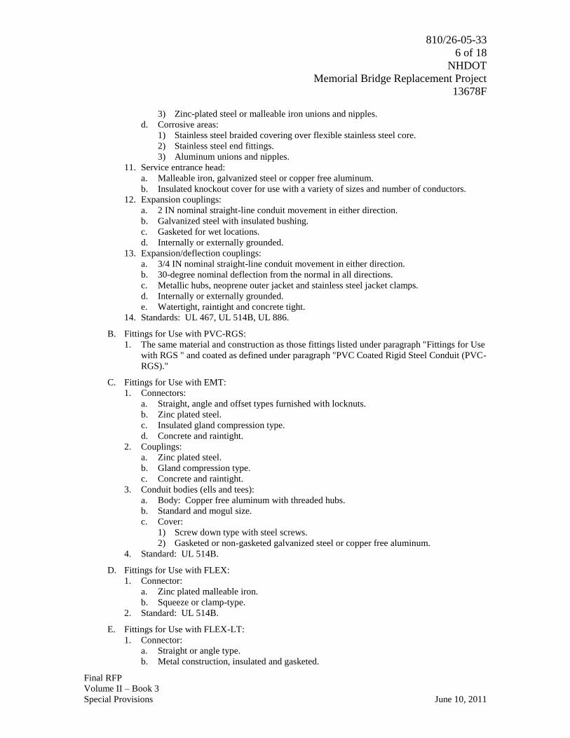
810/26-05-33
6 of 18
NHDOT
Memorial Bridge Replacement Project
13678F
Final RFP
Volume II – Book 3
Special Provisions June 10, 2011
3) Zinc-plated steel or malleable iron unions and nipples.
d. Corrosive areas:
1) Stainless steel braided covering over flexible stainless steel core.
2) Stainless steel end fittings.
3) Aluminum unions and nipples.
11. Service entrance head:
a. Malleable iron, galvanized steel or copper free aluminum.
b. Insulated knockout cover for use with a variety of sizes and number of conductors.
12. Expansion couplings:
a. 2 IN nominal straight-line conduit movement in either direction.
b. Galvanized steel with insulated bushing.
c. Gasketed for wet locations.
d. Internally or externally grounded.
13. Expansion/deflection couplings:
a. 3/4 IN nominal straight-line conduit movement in either direction.
b. 30-degree nominal deflection from the normal in all directions.
c. Metallic hubs, neoprene outer jacket and stainless steel jacket clamps.
d. Internally or externally grounded.
e. Watertight, raintight and concrete tight.
14. Standards: UL 467, UL 514B, UL 886.
B. Fittings for Use with PVC-RGS:
1. The same material and construction as those fittings listed under paragraph "Fittings for Use
with RGS " and coated as defined under paragraph "PVC Coated Rigid Steel Conduit (PVC-
RGS)."
C. Fittings for Use with EMT:
1. Connectors:
a. Straight, angle and offset types furnished with locknuts.
b. Zinc plated steel.
c. Insulated gland compression type.
d. Concrete and raintight.
2. Couplings:
a. Zinc plated steel.
b. Gland compression type.
c. Concrete and raintight.
3. Conduit bodies (ells and tees):
a. Body: Copper free aluminum with threaded hubs.
b. Standard and mogul size.
c. Cover:
1) Screw down type with steel screws.
2) Gasketed or non-gasketed galvanized steel or copper free aluminum.
4. Standard: UL 514B.
D. Fittings for Use with FLEX:
1. Connector:
a. Zinc plated malleable iron.
b. Squeeze or clamp-type.
2. Standard: UL 514B.
E. Fittings for Use with FLEX-LT:
1. Connector:
a. Straight or angle type.
b. Metal construction, insulated and gasketed.

810/26-05-33
7 of 18
NHDOT
Memorial Bridge Replacement Project
13678F
Final RFP
Volume II – Book 3
Special Provisions June 10, 2011
c. Composed of locknut, grounding ferrule and gland compression nut.
d. Liquid tight.
2. Standards: UL 467, UL 514B.
F. Fittings for Use with Rigid Non-Metallic PVC Conduit:
1. Coupling, adapters and conduit bodies:
a. Same material, thickness, and construction as the conduits with which they are used.
b. Homogeneous plastic free from visible cracks, holes or foreign inclusions.
c. Bore smooth and free of blisters, nicks or other imperfections which could damage the
conductor.
2. Solvent cement for welding fittings shall be supplied by the same manufacturer as the
conduit and fittings.
3. Standards: ASTM D2564, NEMA TC 3, UL 651, UL 514B.
G. Weather and Corrosion Protection Tape:
1. PVC based tape, 10 mils thick.
2. Protection against moisture, acids, alkalis, salts and sewage and suitable for direct bury.
3. Used with appropriate pipe primer.
2.7 ALL RACEWAY AND FITTINGS
A. Mark Products:
1. Identify the nominal trade size on the product.
2. Stamp with the name or trademark of the manufacturer.
2.8 OUTLET BOXES
A. Metallic Outlet Boxes:
1. Hot-dip galvanized steel.
2. Conduit knockouts and grounding pigtail.
3. Styles:
a. 2 IN x 3 IN rectangle.
b. 4 IN square.
c. 4 IN octagon.
d. Masonry/tile.
4. Accessories:
a. Flat blank cover plates.
b. Barriers.
c. Extension, plaster or tile rings.
d. Box supporting brackets in stud walls.
e. Adjustable bar hangers.
5. Standards: NEMA/ANSI OS 1, UL 514A.
B. Cast Outlet Boxes:
1. Zinc plated cast iron or die-cast copper free aluminum with manufacturers standard finish.
2. Threaded hubs and grounding screw.
3. Styles:
a. "FS" or "FD".
b. "Bell".
c. Single or multiple gang and tandem.
d. "EDS" or "EFS" for hazardous locations.
4. Accessories: 40 mil PVC exterior coating and 2 mil urethane interior coating.
5. Standards: UL 514A, UL 886.
C. See Specification Section 26 27 26 for wiring devices, wallplates and coverplates.

810/26-05-33
8 of 18
NHDOT
Memorial Bridge Replacement Project
13678F
Final RFP
Volume II – Book 3
Special Provisions June 10, 2011
2.9 PULL AND JUNCTION BOXES
A. NEMA 1 Rated:
1. Body and cover: 14 GA minimum, galvanized steel or 14 GA minimum, steel finished with
rust inhibiting primer and manufacturers standard paint inside and out.
2. With or without concentric knockouts on four (4) sides.
3. Flat cover fastened with screws.
B. NEMA 4 Rated:
1. Body and cover: 14 GA steel finished with rust inhibiting primer and manufacturers
standard paint inside and out.
2. Seams continuously welded and ground smooth.
3. No knockouts.
4. External mounting flanges.
5. Hinged or non-hinged cover held closed with stainless steel screws and clamps.
6. Cover with oil resistant gasket.
C. NEMA 4X Rated (metallic):
1. Body and cover: 14 GA Type 304 or 316 stainless steel.
2. Seams continuously welded and ground smooth.
3. No knockouts.
4. External mounting flanges.
5. Hinged door and stainless steel screws and clamps.
6. Door with oil-resistant gasket.
D. NEMA 4X Rated (non-metallic):
1. Body and cover: Ultraviolet light protected fiberglass-reinforced polyester boxes.
2. No knockouts.
3. External mounting flanges.
4. Hinged door with quick release latches and padlocking hasp.
5. Door with oil resistant gasket.
E. NEMA 7 and NEMA 9 Rated:
1. Cast gray iron alloy or copper-free aluminum with manufacturers standard finish.
2. Drilled and tapped openings or tapered threaded hub.
3. Cover bolted-down with stainless steel bolts or threaded cover with neoprene gasket.
4. External mounting flanges.
5. Grounding lug.
6. Accessories: 40 mil PVC exterior coating and 2 mil urethane interior coating.
F. NEMA 12 Rated:
1. Body and cover:
a. 14 GA steel finished with rust inhibiting primer and manufacturers standard paint inside
and out.
b. Type 5052 H-32 aluminum, unpainted.
2. Seams continuously welded and ground smooth.
3. No knockouts.
4. External mounting flanges.
5. Non-hinged cover held closed with captivated cover screws threaded into sealed wells or
hinged cover held closed with stainless steel screws and clamps.
6. Flat door with oil resistant gasket.
G. Miscellaneous Accessories:
1. Rigid handles for covers larger than 9 SF or heavier than 25 LBS.
2. Split covers when heavier than 25 LBS.

810/26-05-33
9 of 18
NHDOT
Memorial Bridge Replacement Project
13678F
Final RFP
Volume II – Book 3
Special Provisions June 10, 2011
3. Weldnuts for mounting optional panels and terminal kits.
4. Terminal blocks: Screw-post barrier-type, rated 600 volt and 20 ampere minimum.
H. Standards: NEMA 250, UL 50.
2.10 SUPPORT SYSTEMS
A. Multi-conduit Surface or Trapeze Type Support and Pull or Junction Box Supports:
1. Material requirements.
a. Galvanized steel: ASTM A123 or ASTM A153.
b. Stainless steel: AISI Type 316.
c. PVC coat galvanized steel: ASTM A123 or ASTM A153 and 20 mil PVC coating.
B. Single Conduit and Outlet Box Support Fasteners:
1. Material requirements:
a. Zinc plated steel.
b. Stainless steel.
c. Malleable iron.
d. PVC coat malleable iron or steel: 20 mil PVC coating.
e. Steel protected with zinc phosphate and oil finish.
2.11 OPENINGS AND PENETRATONS IN WALLS AND FLOORS
A. Sleeves, smoke and fire stop fitting through walls and floors:
1. See Specification Section 01 73 20.
PART 3 - EXECUTION
3.1 RACEWAY INSTALLATION - GENERAL
A. Shall be in accordance with the requirements of:
1. NFPA 70.
2. Manufacturer instructions.
B. Size of Raceways:
1. Raceway sizes are shown on the Drawings, if not shown on the Drawings, then size in
accordance with NFPA 70.
2. Unless specifically indicated otherwise, the minimum raceway size shall be:
a. Conduit: 3/4 IN.
b. Wireway: 2-1/2 IN x 2-1/2 IN.
C. Field Bending and Cutting of Conduits:
1. Utilize tools and equipment recommended by the manufacturer of the conduit, designed for
the purpose and the conduit material to make all field bends and cuts.
2. Do not reduce the internal diameter of the conduit when making conduit bends.
3. Prepare tools and equipment to prevent damage to the PVC coating.
4. Degrease threads after threading and apply a zinc rich paint.
5. Debur interior and exterior after cutting.
D. Male threads of conduit systems shall be coated with an electrically conductive anti-seize
compound.
E. The protective coating integrity of conduits, fittings, outlet, pull and junction boxes and
accessories shall be maintained.
1. Repair galvanized components utilizing a zinc rich paint.
2. Repair painted components utilizing touch up paint provided by or approved by the
manufacturer.

810/26-05-33
10 of 18
NHDOT
Memorial Bridge Replacement Project
13678F
Final RFP
Volume II – Book 3
Special Provisions June 10, 2011
3. Repair PVC coated components utilizing a patching compound, of the same material as the
coating, provided by the manufacturer of the conduit; or a self-adhesive, highly
conformable, cross-linked silicone composition strip, followed by a protective coating of
vinyl tape.
a. Total nominal thickness: 40 mil.
4. Repair surfaces which will be inaccessible after installation prior to installation.
F. Remove moisture and debris from conduit before wire is pulled into place.
1. Pull mandrel with diameter nominally 1/4 IN smaller than the interior of the conduit, to
remove obstructions.
2. Swab conduit by pulling a clean, tight-fitting rag through the conduit.
3. Tightly plug ends of conduit with tapered wood plugs or plastic inserts until wire is pulled.
G. Only nylon or polyethylene rope shall be used to pull wire and cable in conduit systems.
H. Where portions of a raceway are subject to different temperatures and where condensation is
known to be a problem, as in cold storage areas of buildings or where passing from the interior
to the exterior of a building, the raceway shall be sealed to prevent circulation of warm air to
colder section of the raceway.
I. Fill openings in walls, floors, and ceilings and finish flush with surface.
1. See Specification Section 01 73 20.
3.2 RACEWAY ROUTING
A. Raceways shall be routed in the field unless otherwise indicated.
1. Conduit and fittings shall be installed, as required, for a complete system that has a neat
appearance and is in compliance with all applicable codes.
2. Run in straight lines parallel to or at right angles to building lines.
3. Do not route conduits:
a. Through areas of high ambient temperature or radiant heat.
b. In suspended concrete slabs.
4. Conduit shall not interfere with, or prevent access to, piping, valves, ductwork, or other
equipment for operation, maintenance and repair.
5. Provide pull boxes or conduit bodies as needed so that there is a maximum of 360 degrees
of bends in the conduit run or in long straight runs to limit pulling tensions.
B. All rigid conduits within a structure shall be installed exposed except as follows:
1. As indicated on the Drawings.
2. Concealed above gypsum wall board or acoustical tile suspended ceilings.
3. Concealed within stud frame, poured concrete, concrete block and brick walls of an
architecturally finished area.
C. Maintain minimum spacing between parallel conduit and piping runs in accordance with the
following when the runs are greater than 30 FT:
1. Between instrumentation and telecommunication: 1 IN.
2. Between instrumentation and 125 V, 48 V and 24 Vdc, 2 IN.
3. Between instrumentation and 600 V and less AC power or control: 6 IN.
4. Between instrumentation and greater than 600 Vac power: 12 IN.
5. Between telecommunication and 125 V, 48 V and 24 Vdc, 2 IN.
6. Between telecommunication and 600 V and less AC power or control: 6 IN.
7. Between telecommunication and greater than 600 Vac power: 12 IN.
8. Between 125 V, 48 V and 24 Vdc and 600 V and less AC power or control: 2 IN.
9. Between 125 V, 48 V and 24 Vdc and greater than 600 Vac power: 2 IN.
10. Between 600 V and less AC and greater than 600 Vac: 2 IN.
11. Between process, gas, air and water pipes: 6 IN.

810/26-05-33
11 of 18
NHDOT
Memorial Bridge Replacement Project
13678F
Final RFP
Volume II – Book 3
Special Provisions June 10, 2011
D. Conduits shall be installed to eliminate moisture pockets.
1. Where water cannot drain to openings, provide drain fittings in the low spots of the conduit
run.
E. Conduit shall not be routed on the exterior of structures except as specifically indicated on the
Drawings.
F. Where sufficient room exists within the housing of roof-mounted equipment, the conduit shall
be stubbed up inside the housing.
G. Provide all required openings in walls, floors, and ceilings for conduit penetration.
1. See Specification Section 01 73 20.
3.3 RACEWAY APPLICATIONS
A. Permitted Raceway Types Per Wire or Cable Types:
1. Power wire or cables: All raceway types.
2. Control wire or cables: All raceway types.
3. Instrumentation cables: Metallic raceway except non-metallic may be used underground.
4. Motor leads from a VFD: RGS, RAC or shielded VFD cables in all other raceways.
5. Telecommunication cables: All raceway types.
B. Permitted Raceway Types Per Area Designations:
1. Dry areas:
a. RGS.
b. RAC.
2. Wet areas:
a. RGS.
b. RAC.
3. Corrosive areas:
a. PVC-RGS.
4. Highly corrosive areas:
a. PVC-RGS.
5. NFPA 70 hazardous areas:
a. RGS.
b. RAC when required by other area designations.
C. Permitted Raceway Types Per Routing Locations:
1. In stud framed walls:
a. EMT.
2. In concrete block or brick walls:
a. PVC-40.
3. Above acoustical tile ceilings:
a. EMT.
b. NEMA 1 rated wireway.
4. Embedded in poured concrete walls and floors:
a. PVC-40.
b. PVC-RGS when emerging from concrete into areas designated as wet, corrosive or
highly corrosive.
5. Beneath floor slab-on-grade:
a. PVC-40.
6. Through floor penetrations, see Specification Section 01 73 20:
a. PVC-RGS in areas designated as wet, corrosive or highly corrosive.
7. Direct buried conduits and ductbanks:
a. PVC-80.

810/26-05-33
12 of 18
NHDOT
Memorial Bridge Replacement Project
13678F
Final RFP
Volume II – Book 3
Special Provisions June 10, 2011
b. 90 degree elbows for transitions to above grade:
1) PVC-RGS.
c. Long sweeping bends greater than 15 degrees:
1) PVC-RGS.
8. Concrete encased ductbanks:
a. PVC-40.
b. PVC-EB.
c. 90 degree elbows for transitions to above grade:
1) PVC-RGS.
d. Long sweeping bends greater than 15 degrees:
1) RGS for sizes 2 IN and larger.
D. FLEX conduits shall be installed for connections to light fixtures, HVAC equipment and other
similar devices above the ceilings.
1. The maximum length shall not exceed:
a. 6 FT to light fixtures.
b. 3 FT to all other equipment.
E. FLEX-LT {and FLEX-NM} conduits shall be install as the final conduit connection to light
fixtures, dry type transformers, motors, electrically operated valves, instrumentation primary
elements, and other electrical equipment that is liable to vibrate.
1. The maximum length shall not exceed:
a. 6 FT to light fixtures.
b. 3 FT to motors.
c. 2 FT to all other equipment.
F. HAZ-FLEX coupling shall be installed as the final conduit to motors, electrically operated
valves, instrumentation primary elements and electrical equipment that is liable to vibrate.
1. The maximum length shall not exceed:
a. 3 FT to motors.
b. 2 FT to all other equipment.
G. NEMA 1 Rated Wireway:
1. Surface mounted in electrical rooms.
2. Surface mounted above removable ceilings tiles of an architecturally finished area.
H. NEMA 3R Wiring Trough:
1. Surface mounted in exterior locations.
I. NEMA 4X Rated Wireway:
1. Surface mounted in areas designated as wet and or corrosive.
J. NEMA 12 Rated Wireway:
1. Surface mounted in areas designated as dry in architecturally and non-architecturally
finished areas.
K. Underground Conduit
1. Duct Spacers/Supports:
a. High density polyethylene or high impact polystyrene.
b. Interlocking.
c. Provide 2 IN minimum spacing between conduits.
d. Accessories, as required:
1) Hold down bars.
2) Ductbank strapping.
2. General Installation Requirements:
a. Ductbank types per location:

810/26-05-33
13 of 18
NHDOT
Memorial Bridge Replacement Project
13678F
Final RFP
Volume II – Book 3
Special Provisions June 10, 2011
1) Concrete encased ductbank:
a) Under roads.
b) Conduits containing medium voltage cables.
c) Pad mounted transformer secondaries.
d) As indicated on the plans.
2) Direct-buried conduit(s):
a) Area/Roadway lighting.
b) As indicated on the plans.
b. Do not place concrete or soil until conduits have been observed by the Engineer.
c. Ductbanks shall be sloped a minimum of 4 IN per 100 FT or as detailed on the
Drawings.
1) Low points shall be at manholes or handholes.
d. During construction and after conduit installation is complete, plug the ends of all
conduits.
e. Provide conduit supports and spacers.
1) Place supports and spacers for rigid nonmetallic conduit on maximum centers as
indicated for the following trade sizes:
a) 1 IN and less: 3 FT.
b) 1-1/4 to 3 IN: 5 FT.
c) 3-1/2 to 6 IN: 7 FT.
2) Place supports and spacers for rigid steel conduit on maximum centers as indicated
for the following trade sizes:
a) 1 IN and less: 10 FT.
b) 1-1/4 to 2-1/2 IN: 14 FT.
c) 3 IN and larger: 20 FT.
3) Securely anchor conduits to supports and spacers to prevent movement during
placement of concrete or soil.
f. Stagger conduit joints at intervals of 6 IN vertically.
g. Make conduit joints watertight and in accordance with manufacturer's
recommendations.
h. Accomplish changes in direction of runs exceeding a total of 15 degrees by long sweep
bends having a minimum radius of 25 FT.
1) Sweep bends may be made up of one or more curved or straight sections or
combinations thereof.
i. Furnish manufactured bends at end of runs.
1) Minimum radius of 18 IN for conduits less than 3 IN trade size and 36 IN for
conduits 3 IN trade size and larger.
j. Field cuts requiring tapers shall be made with the proper tools and shall match factory
tapers.
k. After the conduit run has been completed:
1) Prove joint integrity and test for out-of-round duct by pulling a test mandrel
through each conduit.
a) Test mandrel:
(1) Length: Not less than 12 IN
(2) Diameter: Approximately 1/4 IN less than the inside diameter of the
conduit.
2) Clean the conduit by pulling a heavy duty wire brush mandrel followed by a rubber
duct swab through each conduit.
l. Pneumatic rodding may be used to draw in lead wire.
1) Install a heavy nylon cord free of kinks and splices in all unused new ducts.
2) Extend cord 3 FT beyond ends of conduit.

810/26-05-33
14 of 18
NHDOT
Memorial Bridge Replacement Project
13678F
Final RFP
Volume II – Book 3
Special Provisions June 10, 2011
m. Transition from rigid non-metallic conduit to rigid metallic conduit, per Specification
Section 26 05 33, prior to entering a structure or going above ground.
1) Except rigid non-metallic conduit may be extended directly to manholes,
handholes, pad mounted transformer boxes and other exterior pad mounted
electrical equipment where the conduit is concealed within the enclosure.
2) Terminate rigid PVC conduits with end bells.
3) Terminate steel conduits with insulated bushings.
n. Place warning tape in trench directly over ductbanks, direct-buried conduit, and direct-
buried wire and cable in accordance with Specification Section 10 14 00.
o. Placement of conduits stubbing into handholes and manholes shall be located to allow
for proper bending radiuses of the cables.
3. Concrete Encased Ductbank:
a. Ductbank system consists of conduits completely encased in minimum 2 IN of concrete
and with separations between different cabling types as required in Specification
Section 26 05 33 or as detailed on the Drawings.
b. Install so that top of concrete encased duct, at any point:
1) Is not less than 24 IN below grade.
2) Is below pavement sub-grading.
c. Where identified and for a distance 10 FT either side of the area, the concrete shall be
reinforced.
1) The reinforcement shall consist of #4 bars and #4 ties placed 12 IN on center, in
accordance with New Hampshire Department of Transportation Division 500
Specification Sections or as detailed on the Drawings.
d. Conduit supports shall provide a uniform minimum clearance of 2 IN between the
bottom of the trench and the bottom row of conduit.
e. Conduit separators shall provide a uniform minimum clearance of 2 IN between
conduits or as required in Specification Section 26 05 33 for different cabling types.
4. Direct-Buried Conduit(s):
a. Install so that the top of the uppermost conduit, at any point:
1) Is not less than 30 IN below grade.
2) Is below pavement sub-grading.
b. Provide a uniform minimum clearance of 2 IN between conduits or as required in
Specification Section 26 05 33 for different cabling types.
1) Maintain the separation of multiple planes of conduits by one of the following
methods:
a) Install multilevel conduits with the use of conduit supports and separators to
maintain the required separations, and backfill with flowable fill (100 PSI) or
concrete per New Hampshire Department of Transportation Specification
Section 209.
b) Install the multilevel conduits one level at a time.
(1) Each level is backfilled with the appropriate amount of soil and
compaction, per New Hampshire Department of Transportation
Specification Section 209, to maintain the required separations.
3.4 CONDUIT FITTINGS AND ACCESSORIES
A. Conduit Seals:
1. Installed in conduit systems located in hazardous areas as required by the NFPA 70.
B. Rigid non-metallic conduit and fittings shall be joined utilizing solvent cement.
1. Immediately after installation of conduit and fitting, the fitting or conduit shall be rotated
1/4 turn to provide uniform contact.
C. Install Expansion Fittings:

810/26-05-33
15 of 18
NHDOT
Memorial Bridge Replacement Project
13678F
Final RFP
Volume II – Book 3
Special Provisions June 10, 2011
1. Where conduits are exposed to the sun and conduit run is greater than 200 FT.
2. Elsewhere as identified on the Drawings.
D. Install Expansion/Deflection Fittings:
1. Where conduits enter a structure.
a. Except electrical manholes and handholes.
b. Except where the ductbank is tied to the structure with rebar.
2. Where conduits span structural expansions joints.
3. Elsewhere as identified on the Drawings.
E. Threaded connections shall be made wrench-tight.
F. Conduit joints shall be watertight:
1. Where subjected to possible submersion.
2. In areas classified as wet.
3. Underground.
G. Terminate Conduits:
1. In metallic outlet boxes:
a. RGS {and IMC and RAC}:
1) Conduit hub and locknut.
2) Insulated bushing and two (2) locknuts.
3) Use grounding type locknut or bushing when required by NFPA 70.
b. EMT: Compression type connector and locknut.
2. In NEMA 1 rated enclosures:
a. RGS {and IMC and RAC}:
1) Conduit hub and locknut.
2) Insulated bushing and two (2) locknuts.
3) Use grounding type locknut or bushing when required by NFPA 70.
b. EMT: Compression type connector and locknut.
3. In NEMA 12 rated enclosures:
a. Watertight, insulated and gasketed hub and locknut.
b. Use grounding type locknut or bushing when required by NFPA 70.
4. In NEMA 4 and NEMA 4X rated enclosures:
a. Watertight, insulated and gasketed hub and locknut.
5. In NEMA 7 and NEMA 9 rated enclosures:
a. Into an integral threaded hub.
6. When stubbed up through the floor into floor mount equipment:
a. With an insulated grounding bushing on metallic conduits.
b. With end bells on non-metallic conduits.
H. Threadless couplings shall only be used to join new conduit to existing conduit when the
existing conduit end is not threaded and it is not practical or possible to cut threads on the
existing conduit with a pipe threader.
3.5 CONDUIT SUPPORT
A. Permitted multi-conduit surface or trapeze type support system per area designations and conduit
types:
1. Dry or wet and/or hazardous areas:
a. Galvanized system consisting of: Galvanized steel channels and fittings, nuts and
hardware and conduit clamps.
b. Aluminum system consisting of: Aluminum channels, fittings and condit clamps with
stainless steel nuts and hardware.
2. Corrosive areas:

810/26-05-33
16 of 18
NHDOT
Memorial Bridge Replacement Project
13678F
Final RFP
Volume II – Book 3
Special Provisions June 10, 2011
a. Aluminum system consisting of: Aluminum channels, fittings and conduit clamps with
stainless steel nuts and hardware.
b. PVC coated steel system consisting of: PVC coated galvanized steel channels and
fittings and conduit clamps with stainless steel nuts and hardware.
3. Highly corrosive areas:
a. PVC coated steel system consisting of: PVC coated galvanized steel channels and
fittings and conduit clamps with stainless steel nuts and hardware.
4. Conduit type shall be compatible with the support system material.
a. Galvanized steel system may be used with RGS.
b. Stainless steel system may be used with RGS.
c. PVC coated galvanized steel system may be used with PVC-RGS and Fiberglass.
B. Permitted single conduit support fasteners per area designations and conduit types:
1. Architecturally finished areas:
a. Material: Zinc plated steel, or steel protected with zinc phosphate and oil finish.
b. Types of fasteners: Spring type hangers and clips, straps, hangers with bolts, clamps
with bolts and bolt on beam clamps.
c. Provide anti-rattle conduit supports when conduits are routed through metal studs.
2. Dry or wet and/or hazardous areas:
a. Material: Zinc plated steel, stainless steel and malleable iron.
b. Types of fasteners: Straps, hangers with bolts, clamps with bolts and bolt on beam
clamps.
3. Corrosive areas:
a. Material: Stainless steel and PVC coat malleable iron or steel.
b. Types of fasteners: Straps, hangers with bolts, clamps with bolts and bolt on beam
clamps.
4. Highly corrosive areas:
a. Material: PVC coat malleable iron or steel.
b. Types of fasteners: Straps, hangers with bolts, clamps with bolts and bolt on beam
clamps.
5. Conduit type shall be compatible with the support fastener material.
a. Zinc plated steel, steel protected with zinc phosphate and oil finish and malleable iron
fasteners may be used with RGS.
b. Stainless steel system may be used with RGS.
c. PVC coated fasteners may be used with PVC-RGS.
C. Conduit Support General Requirements:
1. Maximum spacing between conduit supports per NFPA 70.
2. Support conduit from the building structure.
3. Do not support conduit from process, gas, air or water piping; or from other conduits.
4. Provide hangers and brackets to limit the maximum uniform load on a single support to
25 LBS or to the maximum uniform load recommended by the manufacturer if the support
is rated less than 25 LBS.
a. Do not exceed maximum concentrated load recommended by the manufacturer on any
support.
b. Conduit hangers:
1) Continuous threaded rods combined with struts or conduit clamps: Do not use
perforated strap hangers and iron bailing wire.
c. Do not use suspended ceiling support systems to support raceways.
d. Hangers in metal roof decks:
1) Utilize fender washers.
2) Not extend above top of ribs.
3) Not interfere with vapor barrier, insulation, or roofing.

810/26-05-33
17 of 18
NHDOT
Memorial Bridge Replacement Project
13678F
Final RFP
Volume II – Book 3
Special Provisions June 10, 2011
5. Conduit support system fasteners:
a. Use sleeve-type expansion anchors as fasteners in masonry wall construction.
b. Do not use concrete nails and powder-driven fasteners.
3.6 OUTLET, PULL AND JUNCTION BOX INSTALLATION
A. General:
1. Install products in accordance with manufacturer's instructions.
2. See Specification Section 26 05 00 and the Drawings for area classifications.
3. Fill unused punched-out, tapped, or threaded hub openings with insert plugs.
4. Size boxes to accommodate quantity of conductors enclosed and quantity of conduits
connected to the box.
B. Outlet Boxes:
1. Permitted uses of metallic outlet boxes:
a. Housing of wiring devices:
1) Recessed in all stud framed walls and ceilings.
2) Recessed in poured concrete, concrete block and brick walls of architecturally
finished areas and exterior building walls.
b. Pull or junction box:
1) Above gypsum wall board or acoustical tile ceilings.
2) Above 10 FT in an architecturally finished area where there is no ceiling.
2. Permitted uses of cast outlet boxes:
a. Housing of wiring devices surface mounted in non-architecturally finished dry, wet,
corrosive, highly corrosive and hazardous areas.
b. Pull and junction box surface mounted in non-architecturally finished dry, wet,
corrosive and highly corrosive areas.
3. Mount device outlet boxes where indicated on the Drawings and at heights as scheduled in
Specification Section 26 05 00.
4. Set device outlet boxes plumb and vertical to the floor.
5. Outlet boxes recessed in walls:
a. Install with appropriate stud wall support brackets or adjustable bar hangers so that they
are flush with the face of the wall.
b. Locate in ungrouted cell of concrete block with bottom edge of box flush with bottom
edge of block and flush with the face of the block.
6. Place barriers between switches in boxes with 277 V switches on opposite phases.
7. Back-to-back are not permitted.
8. When an outlet box is connected to a PVC coated conduit, the box shall also be PVC coated.
C. Pull and Junction Boxes:
1. Install pull or junction boxes in conduit runs where indicated or required to facilitate pulling
of wires or making connections.
a. Make covers of boxes accessible.
2. Permitted uses of NEMA 1 enclosure:
a. Pull or junction box surface mounted above removable ceiling tiles of an architecturally
finished area.
3. Permitted uses of NEMA 4 enclosure:
a. Pull or junction box surface mounted in areas designated as wet.
4. Permitted uses of NEMA 4X metallic enclosure:
a. Pull or junction box surface mounted in areas designated as wet and/or corrosive.
5. Permitted uses of NEMA 7 enclosure:
a. Pull or junction box surface mounted in areas designated as Class I hazardous.
1) Provide PVC coating in corrosive and highly corrosive areas when PVC coated
conduit is used.
810/26-05-33
18 of 18
NHDOT
Memorial Bridge Replacement Project
13678F
Final RFP
Volume II – Book 3
Special Provisions June 10, 2011
6. Permitted uses of NEMA 12 enclosure:
a. Pull or junction box surface mounted in areas designated as dry.
END OF SECTION

810/26-05-45
1 of 7
NHDOT
Memorial Bridge Replacement Project
13678F
Final RFP
Volume II – Book 3
Special Provisions June 10, 2011
SECTION 26 05 45
DROOP CABLE SYSTEM
PART 1 - GENERAL
1.1 SUMMARY
A. Section Includes:
1. Basic requirements for droop cable system.
B. Related Specification Sections include but are not necessarily limited to:
1. New Hampshire Department of Transportation Section 105 - Control of the Work.
1.2 QUALITY ASSURANCE
A. Referenced Standards:
1. Aluminum Association (AA).
2. American Iron and Steel Institute (AISI).
3. ASTM International (ASTM):
a. A123, Standard Specification for Zinc (Hot-Dip Galvanized) Coatings on Iron and Steel
Products.
b. A153, Standard Specification for Zinc Coating (Hot-Dip) on Iron and Steel Hardware.
4. ETL Testing Laboratories (ETL).
5. Institute of Electrical and Electronics Engineers, Inc. (IEEE):
a. C2, National Electrical Safety Code (NESC).
6. National Electrical Manufacturers Association (NEMA):
a. 250, Enclosures for Electrical Equipment (1000 Volts Maximum).
7. National Fire Protection Association (NFPA):
a. 70, National Electrical Code (NEC).
8. Underwriters Laboratories, Inc. (UL).
1.3 SUBMITTALS
A. Shop Drawings:
1. See New Hampshire Department of Transportation Specification Section 105 for
requirements for the mechanics and administration of submittal process.
2. General requirements:
a. Provide manufacturer's technical information on products to be used, including product
descriptive bulletin.
b. Include data sheets that include manufacturer's name and product model number.
1) Clearly identify all optional accessories.
c. Acknowledgement that products are UL or ETL listed or are constructed utilizing UL
or ETL recognized components.
d. Manufacturer's delivery, storage, handling and installation instructions.
e. Product installation details.
B. Operation and Maintenance Manuals:
1. See Specification Section 26 05 00 for requirements for the mechanics and administration of
submittal process.
2. The Design-Builder shall furnish complete instructions containing the technical information
required for proper installation, operation and maintenance of each assembly of equipment
supplied. See Specification Section 8.4.

810/26-05-45
2 of 7
NHDOT
Memorial Bridge Replacement Project
13678F
Final RFP
Volume II – Book 3
Special Provisions June 10, 2011
C. Factory Test Data - Information to be submitted:
1. Material undergoing test
2. Description of test performed
3. Results (measured or observed)
4. Value and limits required by ICEA/NEMA Standard for acceptance
D. Insulation Data:
1. Typical published test data of proposed cable insulating compound
a. Physical characteristics
b. Electrical characteristics
2. Must be submitted for approval before accepting shipment from manufacturer
E. Certificate of Compliance:
1. Statement certifying that cable delivered passed the required factory inspections and tests
and complies with all requirements of the contract
PART 2 - PRODUCTS
2.1 MANUFACTURER
A. Manufacturer of the droop cable must be experienced in producing flexible droop cable.
B. Approved Manufacturer for Bronze Insulated Grounding Bushings, Watertight Cable Strain
Relief Fittings, Conduit Expansion Fittings
1. O.Z./Gedney
C. Approved Manufacturer for Breather Fitting
1. Appleton Electric
D. Submit request for substitution in accordance with Specification Section 01 25 13.
2.2 MATERIALS
A. Droop Cables
1. True length of each cable between the droop cable terminal cabinets and junction boxes on
the movable span must be determined before cable orders are placed with any manufacturer.
a. No splices or joining of conductors will be permitted.
b. Length of cables must provide sufficient excess length to accommodate pulling eyes,
adequate slack for full range of travel, cable clamping, connections and test samples.
2. Minimum of 20% of the specified conductors shall be provided as spare conductors.
3. Cables shall be designed and manufactured in accordance with:
a. ICEA S-73-532, NEMA WC-57 (22-26 AWG)
b. ICEA S-95-658, NEMA WC-70 (14 AWG and larger)
4. Configuration
a. Multiple conductor extra flexible copper conductors
1) Conductors shall be annealed copper and stranded in accordance with ASTM B-
174 for 10 AWG and smaller, and ASTM B-172 for 9 AWG and larger. Stranding
shall be per Section 2 of ICEA S-95-658, NEMA WC-70, as applicable.
b. Ethylene propylene rubber (EPR) insulation
1) Shall be in accordance with ICEA S-73-532, NEMA WC-57, Table 3-2 (22-16
AWG) for 600V and ICEA S-95-658, NEMA WC-70, Table 3-1 (14 AWG and
larger) for 600V.
c. Cabled with fillers as necessary
d. Binder tape
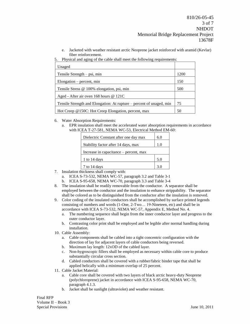
810/26-05-45
3 of 7
NHDOT
Memorial Bridge Replacement Project
13678F
Final RFP
Volume II – Book 3
Special Provisions June 10, 2011
e. Jacketed with weather resistant arctic Neoprene jacket reinforced with aramid (Kevlar)
fiber reinforcement.
5. Physical and aging of the cable shall meet the following requirements:
Unaged
Tensile Strength – psi, min 1200
Elongation – percent, min 150
Tensile Stress @ 100% elongation, psi, min 500
Aged - After air oven 168 hours @ 121C
Tensile Strength and Elongation: At rupture – percent of unaged, min 75
Hot Creep @150C: Hot Creep Elongation, percent, max 50
6. Water Absorption Requirements:
a. EPR insulation shall meet the accelerated water absorption requirements in accordance
with ICEA T-27-581, NEMA WC-53, Electrical Method EM-60:
Dielectric Constant after one day max 6.0
Stability factor after 14 days, max 1.0
Increase in capacitance – percent, max
1 to 14 days 5.0
7 to 14 days 3.0
7. Insulation thickness shall comply with:
a. ICEA S-73-532, NEMA WC-57, paragraph 3.2 and Table 3-1
b. ICEA S-95-658, NEMA WC-70, paragraph 3.3 and Table 3-4
8. The insulation shall be readily removable from the conductor. A separator shall be
employed between the conductor and the insulation to enhance strippability. The separator
shall be colored as to be distinguished from the conductor after the insulation is removed.
9. Color coding of the insulated conductors shall be accomplished by surface printed legends
consisting of numbers and words (1-One, 2-Two… 19-Nineteen, etc) and shall be in
accordance with ICEA S-73-532, NEMA WC-57, Appendix E, Method No. 4.
a. The numbering sequence shall begin from the inner conductor layer and progress to the
outer conductor layer.
b. Contrasting color print shall be employed and be legible after normal handling during
installation.
10. Cable Assembly:
a. Cable components shall be cabled into a tight concentric configuration with the
direction of lay for adjacent layers of cable conductors being reversed.
b. Maximum lay length: 12xOD of the cabled layer.
c. Non-hygroscopic fillers shall be employed as necessary within cable core to produce
substantially circular cross section.
d. Cabled conductors shall be covered with a rubber/fabric binder tape that shall be
applied helically with a minimum overlap of 25 percent.
11. Cable Jacket Material:
a. Cable core shall be covered with two layers of black arctic heavy-duty Neoprene
(polychloroprene) jacket in accordance with ICEA S-95-658, NEMA WC-70,
paragraph 4.1.3.
b. Jacket shall be sunlight (ultraviolet) and weather resistant.

810/26-05-45
4 of 7
NHDOT
Memorial Bridge Replacement Project
13678F
Final RFP
Volume II – Book 3
Special Provisions June 10, 2011
c. Jacket shall meet the following physical and thermal aging requirements:
Unaged
Tensile Strength – psi, min 1800
Elongation – percent, min 300
Tensile Stress @ 200% elongation, psi, min 500
Aged
After air oven 168 hours @ 100C Tensile Strength and Elongation: At
rupture – percent of unaged, min
85/65
After oil immersion 18 hours @ 121C Tensile Strength and
Elongation: At rupture – percent of unaged, min
60
d. The two-layer cable jacket thickness shall be as follows:
Calculated Diameter of Cable Under Jacket (inches) Jacket Average Thickness (mils)
Less than 0.325 60
0.326-0.430 80
0.431-0.540 95
0.541-0.640 110
0.641-0.740 125
0.741-0.850 140
0.851-1.000 155
1.001-1.320 170
1.321-1.550 190
1.551-1.820 205
1.821-2.050 220
2.051-2.300 235
2.301-2.550 250
2.551-2.800 265
2.801-3.100 280
3.101-3.500 295
3.501-3.950 310
3.951-4.450 330
4.451-5.000 345
12. Communication Conductors:
a. Fiber optic
1) If required.
2) Individual fiber cables shall be composed of 62.5/125/250 micrometer multimode
fiber, encased in gel-filled loose tubes, cabled, a central strength member, water
swellable tape, aramid fiber strength member, and a polypropylene jacket.
b. Allow provision for communication conductors as per manufacturer instructions.
13. Packaging of the finished cable shall be on reels capable of supporting the weight during
transportation and normal handling. Cable ends shall be suitably sealed to prevent moisture
from entering the conductor core area during shipping. The reel designated to be spare shall
be encased with wooden slats affixed to the entire perimeter of the reel to protect the cable
while in storage.
B. Droop Cable Terminal Cabinets and Junction Boxes
1. Droop Cable Terminal Cabinet:
a. Shall be furnished and installed to provide termination for the droop cables.

810/26-05-45
5 of 7
NHDOT
Memorial Bridge Replacement Project
13678F
Final RFP
Volume II – Book 3
Special Provisions June 10, 2011
b. Shall be sized to accommodate mounting of all terminal blocks and to provide ample
space between blocks for routing the wires.
c. Terminal blocks shall be provided for connections of all conductors in the droop cables.
a) Sufficient terminals shall be provided for termination of all spare conductors
and other conductors to be terminated inside the cabinet.
b) Shall be one-piece blocks suitable for use in highly corrosive atmospheres
d. Two doors
1) Shall be constructed of No. 10 gauge steel sheet, suitably reinforced
2) Shall be provided with a three-point, vault-type latch
3) Shall have rubber gaskets
e. Floor mounted
f. NEMA 4X type enclosure
g. 12 inch floor stands
h. Fabricated from No. 10 gauge steel sheet
2. Ends of Conduits:
a. Ends of all conduits projecting into terminal cabinets and junction boxes shall be
provided with bronze insulated grounding bushings. The insulated portion shall be of
molded phenolic compound, and each fitting shall have a screw type combination lug
for bonding.
b. All bushings in any box or enclosure shall be bonded together with No. 8 AWG bare
copper wire.
3. Watertight Cable Strain Relief Fitting:
a. Shall be used to complete each droop cable termination at all terminal cabinets and
junction boxes.
4. Junction Boxes:
a. Aluminum NEMA 4X
b. Shall have a continuous hinge on one side and screw type clasps on the remaining three
sides.
c. Shall be provided with a stainless steel NEMA 4X breather fitting to minimize
condensation
C. Cable Supports:
1. On either end of the traveling section of cable, all droop cables shall be supported with
heavy-duty, double-eye, split mesh, stainless steel cable grips.
2. Each cable shall be supported by two mesh grips
a. one attached to support structure on fixed tower
b. one attached to support structure on movable span
3. All vertical and horizontal installations of droop cable shall be attached to support plates by
stainless steel U-bolts and double nuts.
a. U-bolts shall be fabricated with stainless steel saddles welded in place
b. Shall be sized to match droop cable diameter
4. Framing channel will not be an acceptable support system.
D. Conduit:
1. All conduit shall be rigid aluminum conduit.
2. Shall be manufactured in conformance to UL and ANSI standards
3. Bends and offsets shall be made by cold bending using approved methods and equipment if
required.
4. Shall be securely clamped and supported using stainless steel U-bolts
a. U-bolts shall be provided with medium-series lock washers and hexagonal nuts.
b. Bolts, nuts, and washers shall be of stainless steel in conformance with the Standard
Specifications for Stainless and Heat-Resisting Steel Bars and Shapes, ASTM
Designation A276.

810/26-05-45
6 of 7
NHDOT
Memorial Bridge Replacement Project
13678F
Final RFP
Volume II – Book 3
Special Provisions June 10, 2011
5. Conduit expansion fittings shall be bronze/neoprene deflection/expansion fittings and shall
be provided with flexible bonding jumpers to maintain electrical continuity across the joints.
6. Ends of all conduits projecting into boxes and equipment enclosures shall be provided with
bronze insulated grounding bushings. The insulated portion shall be of molded phenolic
compound, and each fitting shall have a screw type combination lug for bonding.
a. All bushings in any box or enclosure shall be bonded together with No. 8 AWG bare
copper wire.
7. All conduits shall be cleaned before and after installation. Upon completion of conduit and
box installation, the Design-Builder shall clear each conduit by snaking with a steel band to
which shall be attached an approved tube cleaner equipped with a mandrel of a diameter not
less than 85 percent of the nominal inside diameter of the conduit and with a wire brush of
the same diameter as the conduit. The cable shall then be drawn into the conduit.
PART 3 - EXECUTION
3.1 TESTING
A. Shop Testing
1. Individual insulated conductors to be incorporated in cable shall be tested for quality of
production prior to assembly and fabrication of droop cables
2. Tests to be performed after cable is completely assembled:
a. High voltage testing
b. Insulation resistance testing
c. Conductor resistance testing
3. Tests to be performed on section of cable sample taken from each reel in accordance with
ICEA/NEMA standards:
a. Individual conductors shall be tested in accordance with ICEA S-95-658, NEMA WC-
70, Table 3-4
b. Finished cable shall withstand between each conductor and all other conductors an AC
(rms) voltage in accordance with:
1) ICEA S-73-532, NEMA WC-57, table 3-3, paragraphs 3.4 and 6.17.1 (22-16
AWG)
2) ICEA S-95-658, NEMA WC-70, table 3-4, paragraphs 3.6.2 and 6.10.1.1 (14
AWG and larger)
3) ICEA T-27-581, NEMA WC-53, paragraph 2.2.2
c. Insulation resistance shall be measured after completed AC voltage test in accordance
with:
1) ICEA S-73-532, NEMA WC-57, paragraphs 3.5 and 6.18
2) ICEA S-95-658, NEMA WC-70, paragraphs 3.6.3 and 6.10.2 (14 AWG and larger)
3) ICEA T-27-581, NEMA WC-53, paragraph 2.3
4) Insulation resistance constant (IRK) for EPR insulation shall be 10,000 in
accordance with ICEA S-95-658, NEMA WC-70, paragraph 3.6.3, and table 3-7
for insulation Class E-2
d. The DC resistance of each conductor in the completed cable shall be measured and
comply with:
1) ICEA S-73-532, NEMA WC-57, paragraph 2.3.4
2) ICEA S-95-658, NEMA WC-70, paragraph 2.3 (14 AWG and larger)
3) ICEA T-27-581, NEMA WC-53, paragraph 2.1
B. Field Testing
1. Test methods for measuring insulation resistance of cables installed in the field shall be in
accordance with the specified NEMA Publications.

810/26-05-45
7 of 7
NHDOT
Memorial Bridge Replacement Project
13678F
Final RFP
Volume II – Book 3
Special Provisions June 10, 2011
2. Test equipment shall include a megohm meter capable of generating a constant 1000V DC
source, calibrated in a range legible from 0 to 1000 megohms and up to infinity, with heavy-
duty, rubber-insulated, alligator-clip leads, and a guard-circuit terminal available if used.
3. Polarity for connecting the megohm meter to cable under test and the duration of time for
electrifying the cable before taking the resistance reading shall be in accordance with the
NEMA Publication.
4. Measured values of insulation resistance of each conductor shall be recorded for comparison
with the factory test values. the failure of any conductor in an installed droop cable to
demonstrate satisfactory insulation resistance will be cause for the rejection of the droop
cable. Should this occur, the rejected cable shall be promptly removed and replaced with a
new cable subject to all aforementioned tests and acceptances.
5. Records of the measured insulation resistance for each cable, the cable length installed,
cable and reel identifications, date of test, and ambient temperature shall be taken. the test
results and data shall be submitted to the Engineer for approval in addition to submission of
a certificate identifying the test equipment used stating its accuracy within the limits rated
by the manufacturer.
3.2 INSTALLATION
A. Equipment and installation shall conform to AASHTO Standard Specifications for Movable
Highway Bridges.
B. Materials and construction shall conform to NFPA 70/NEC latest revision and any applicable
local rules and ordinances.
1. All required permits and approvals must be obtained.
C. All work shall be in conformance with the requirements of the United States Coast Guard.
END OF SECTION

810/26-05-48
1 of 4
NHDOT
Memorial Bridge Replacement Project
13678F
Final RFP
Volume II – Book 3
Special Provisions June 10, 2011
SECTION 26 05 48
SEISMIC BRACING SYSTEMS
PART 1 - GENERAL
1.1 SUMMARY
A. Section Includes:
1. The design and installation of seismic bracing and anchorage required for electrical
equipment, conduit, cable tray, and bus ducts.
B. Related Sections include but are not necessarily limited to:
1. New Hampshire Department of Transportation Section 105 - Control of the Work.
2. Section 01 25 13 - Product Substitution.
1.2 QUALITY ASSURANCE
A. Referenced Standards:
1. ASTM International (ASTM):
a. A36, Standard Specification for Carbon Structural Steel.
b. A307, Standard Specification Carbon Steel Bolts and Studs, 60,000 psi Tensile
Strength.
c. F1554, Standard Specification for Anchor Bolts, Steel, 36, 55, and 105-ksi Yield
Strength.
2. Building code:
a. International Building Code (IBC).
b. International Conference of Building Officials (ICBO).
1.3 SYSTEM DESCRIPTION
A. Design-Builder is responsible for design and installation of seismic bracing and anchorage
systems.
B. Description of Systems:
1. Transverse and longitudinal bracing for seismic forces on suspended electrical systems
including conduit, cable tray, bus duct, and equipment.
2. Anchorage of floor and roof mounted electrical equipment.
C. Seismic Design Requirements:
1. Seismic design criteria: Provide bracing and anchoring for equipment, conduit, cable tray,
bust duct, designed, constructed, and installed to resist stresses produced by lateral forces.
D. Design and install seismic anchorage and bracing for all floor or roof mounted equipment
weighing 400 LBS or more and all suspended or wall mounted equipment weighing 20 LBS or
more.
E. The following components are exempt from the requirements of this Specification Section:
1. Electrical components in structures assigned to Seismic Design Category C provided that
the importance factor (Ip) is equal to 1.0.
2. Electrical components in Seismic Design Categories D, E, and F where Ip = 1.0 and flexible
connections between the components and associated ductwork, piping, and conduit are
provided and that are mounted at 4 FT (1.22 m) or less above a floor level and weigh
400 LBS (1780 N)or less.

810/26-05-48
2 of 4
NHDOT
Memorial Bridge Replacement Project
13678F
Final RFP
Volume II – Book 3
Special Provisions June 10, 2011
3. Electrical components in Seismic Design Categories D, E, and F weighing 20 LBS (95 N) or
less where Ip = 1.0 and flexible connections between the components and conduit are
provided, or for distribution systems, weighing 5 LBS/FT (7 N/m) or less.
F. Seismic forces shall be presumed to act through the center of mass of the equipment in a
direction that will produce the largest single anchor force.
1.4 SUBMITTALS
A. Shop Drawings:
1. See New Hampshire Department of Transportation Specification Section 105 for
requirements for the mechanics and administration of submittal process.
2. Product technical data:
a. Seismic control devices.
3. Fabrication and/or layout drawings:
a. Layout and mounting detail drawings showing system and proposed brace locations for
all systems including pre-engineered systems.
b. The specific detail for each type of brace or anchor must be referenced on a plan that
identifies the required location.
1) Supplying a book of details without referencing the proper detail to a specific
location on a plan is not acceptable.
c. Structural calculations for required lateral force level for each component.
d. All submittals, including pre-approved systems, shall be signed and sealed by a licensed
engineer, licensed in the state in which the project is located.
PART 2 - PRODUCTS
2.1 ACCEPTABLE MANUFACTURERS
A. Subject to compliance with the Contract Documents, the following manufacturers are
acceptable:
1. Pre-engineered suspended bracing systems:
a. International Seismic Application Technology (ISAT) “Engineered Seismic Bracing of
Suspended Utilities”.
b. Unistrut.
c. Tolco.
d. B-Line.
2. Custom engineered systems designed using specified criteria and common building
materials.
B. Submit request for substitution in accordance with Specification Section 01 25 13.
2.2 EQUIPMENT ANCHORS AND SUPPORTS
A. Drilled-in-place concrete anchors shall have an approved ICBO Evaluation Services Report.
B. Cast-in-place anchors shall comply with ASTM A36, ASTM A307, or ASTM F1554, 36 ksi.
C. Anchors permanently exposed to weather or corrosive environments shall be stainless steel or
hot-dipped galvanized.
D. Structural steel for supports: ASTM A36.
E. Cold formed metal and connection material: Unistrut.
F. Any details provided are based on assumed equipment and arrangement.

810/26-05-48
3 of 4
NHDOT
Memorial Bridge Replacement Project
13678F
Final RFP
Volume II – Book 3
Special Provisions June 10, 2011
1. Design-Builder shall be responsible for design and acquiring approval for support and
anchorage of equipment and arrangement which varies from equipment and arrangement
assumed in detail provided.
PART 3 - EXECUTION
3.1 GENERAL REQUIREMENTS
A. Every run which requires bracing shall have a minimum of two (2) transverse braces and one (1)
longitudinal brace.
1. A “run” is defined as suspended pipe, conduit, cable tray, bus ductor trapeze rack having a
minimum 5 FT straight run length.
B. Brace spacing shall not exceed the maximum allowable brace spacing as engineered by the
manufacturer or custom bracing designer.
C. Bracing may be omitted from conduit, cable tray and bus duct runs less than 5 FT in length.
D. Bracing may be omitted from conduit, cable tray and bus duct runs where rod hung supports of
less than 12 IN. (305mm) in length are required.
1. All unbraced suspended utility systems having 2 IN conduit and larger or systems weighing
more then 5 LBS/FT shall be installed with a minimum 6 IN clearance to suspended ceiling
vertical hanger wires.
2. The conduit, cable tray, or bus duct shall be installed such that the lateral motion of the
members will not cause damaging impact with other systems or structural members or loss
of vertical support.
E. A longitudinal brace at a 90 degree change in direction may act as a transverse brace if it is
located within 2 FT of the change in direction.
F. A transverse brace may act as a longitudinal brace if it is located within 2 FT of a change in
direction and if the brace arm and anchorage have been sized to meet or exceed the requirements
of the longitudinal brace.
G. When bracing equipment or a utility system that is suspended from an overhead deck, brace back
to the overhead deck or to the supporting structure supporting the deck.
1. Do not brace to another element of the structure which may respond differently during a
seismic event.
H. Obtain approval from the Structural Engineer prior to attaching any brace elements to structural
steel or wood framing.
I. When utilizing cable bracing, tension the cable to remove slack without inducing uplift of the
suspended element.
1. Tension seismic bracing system prior to system start-up and adjust if necessary after
equipment start-up.
J. As a general rule, do not mix rigid bracing with cable bracing in the same run.
1. However, once bracing has transitioned a 90 degree change in run direction, the bracing
may switch from rigid to cable or vice versa if required due to a significant change in
overhead deck elevation or to provide an implementable bracing scheme in a congested
area.
K. Install brace members at an angle of 45 degrees from horizontal within a tolerance of plus 2
1/2 degrees or minus 45 degrees provided the brace length is accounted for in design.
1. Brace angle may be increased to 60 degrees provided the brace spacing is reduced to 1/2
that required for a 45 degree brace.

810/26-05-48
4 of 4
NHDOT
Memorial Bridge Replacement Project
13678F
Final RFP
Volume II – Book 3
Special Provisions June 10, 2011
L. Seismic bracing may not pass through a building separation joint.
1. Utility systems that pass through a separation joint must be seismically restrained no greater
than 5 FT from the point of connection.
2. Any hardware designed to accommodate seismic movement across the span of the
separation joint shall be installed per manufacturer's installation and listing instructions.
M. With approval of the Structural Engineer, utility systems that are suspended from the overhead
deck may be braced to load bearing concrete or CMU (concrete masonry) walls provided that the
walls and the overhead decks will respond similarly during a seismic event.
N. Each layer of a multiple layer trapeze rack shall be braced individually based on the weight of
the individual layer.
O. Conduit, cable tray, or bus duct constructed of non ductile material (plastic or fiberglass), shall
have brace spacing reduced to 1/2 of the spacing allowed for ductile materials.
P. Where brace elements are through-bolted, the mounting hole in the element is to be no more
than 1/16 IN in diameter larger then the bolt or threaded rod.
Q. Seismic braces shall directly brace the system and not the hanger.
3.2 SUSPENDED ELECTRICAL SYSTEMS
A. Install seismic bracing for all conduit 2-1/2 IN trade size or greater.
B. All trapeze assemblies supporting conduits, cable trays or bus ducts shall be braced considering
the total weight of the elements on the trapeze.
1. For the purposes of calculating weight, all conduits are to be treated as full.
C. Brace all trapeze racks which support conduit 2-1/2 IN trade size or larger.
1. Brace all other conduit rack, cable tray or bus duct trapezes having a minimum weight in
excess of 10 LBS/LF.
2. Include a minimum 10 percent additional capacity for future additions.
D. Seismic bracing may be omitted from cable trays, conduit and bus ducts suspended by rod hung
supports 12 IN or less in length form the top of the element to the bottom of the structural
attachment of the hanger provided lateral motion will not cause damaging impacts to other
systems or loss of system vertical support.
E. All vertical risers involving conduit 2-1/2 IN in diameter or larger shall include lateral restraint
at maximum 30 FT intervals and at the top and bottom of the riser.
3.3 FLOOR OR ROOF MOUNTED EQUIMENT
A. Provide one (1) anchor on each leg or corner.
1. Support with a minimum of three (3) 3/8 IN DIA anchors.
B. Friction shall be neglected when designing anchors for shear.
C. Vertical seismic forces, when required, shall be presumed to act concurrently with horizontal
seismic forces.
END OF SECTION

810/26-08-13
1 of 7
NHDOT
Memorial Bridge Replacement Project
13678F
Final RFP
Volume II – Book 3
Special Provisions June 10, 2011
SECTION 26 08 13
ACCEPTANCE TESTING
PART 1 - GENERAL
1.1 SUMMARY
A. Section Includes:
1. Basic requirements for acceptance testing.
B. Related Specification Sections include but are not necessarily limited to:
1. New Hampshire Department of Transportation Section 105 - Control of the Work.
2. Section 40 05 05 - Equipment: Basic Requirements.
3. Division 26 - Electrical.
4. Section 26 32 14 - Engine Generator - Diesel.
1.2 QUALITY ASSURANCE
A. Referenced Standards:
1. Institute of Electrical and Electronics Engineers, Inc. (IEEE):
a. 400, Guide for Field Testing and Evaluation of the Insulation of Shielded Power Cable
Systems.
b. 400.3, Guide for Partial Discharge Testing of Power Cable Systems in a Field
Environment.
2. InterNational Electrical Testing Association (NETA):
a. ATS, Standard for Acceptance Testing Specifications for Electric Power Equipment
and Systems.
3. Nationally Recognized Testing Laboratory (NRTL).
4. Telecommunications Industry Association/Electronic Industries Alliance/American National
Standards Institute (TIA/EIA/ANSI):
a. 455-78-B, Optical Fibres - PART 1-40: Measurement Methods and Test Procedures -
Attenuation.
B. Qualifications:
1. Testing firm qualifications: See Specification Section 40 05 05.
2. Field personnel:
a. See Specification Section 40 05 05.
b. As an alternative, supervising technician may be certified by the equipment
manufacturer.
3. Analysis personnel:
a. See Specification Section 40 05 05.
As an alternative, supervising technician may be certified by the equipment
manufacturer.
C. Phasing Diagram:
1. Coordinate with Utility Company for phase rotations and Phase A, B and C markings.
a. Create a phasing diagram showing the coordinated phase rotations with generators and
motors through the transformers.
1.3 SUBMITTALS
A. Shop Drawings:
1. See New Hampshire Department of Transportation Specification Section 105 for
requirements for the mechanics and administration of submittal process.

810/26-08-13
2 of 7
NHDOT
Memorial Bridge Replacement Project
13678F
Final RFP
Volume II – Book 3
Special Provisions June 10, 2011
2. See Specification Section 40 05 05 for electrical equipment and connection testing plan
submittal requirements.
B. Miscellaneous Submittals:
1. See New Hampshire Department of Transportation Specification Section 105 for
requirements for the mechanics and administration of submittal process.
2. Prior to energizing equipment:
a. Coordinated phasing diagram.
b. Photocopies of continuity tests.
3. Within two (2) weeks after successful completion of Demonstration Period (Commissioning
Period):
a. Single report containing information including:
1) Summary of Project.
2) Information from pre-energization testing.
3) See testing and monitoring reporting requirements in Specification Section 40 05
05.
PART 2 - PRODUCTS
2.1 FACTORY QUALITY CONTROL
A. Provide Division 26 equipment with all routing factory tests required by the applicable industry
standards or NRTL.
B. Factory testing will not be accepted in lieu of field acceptance testing requirements specified in
this Specification Section and Specification Section 40 05 05.
PART 3 - EXECUTION
3.1 FIELD QUALITY CONTROL
A. General:
1. See Specification Section 40 05 05.
2. Complete electrical testing in three (3) phases:
a. Pre-energization testing phase.
b. Equipment energized with no load.
c. Equipment energized under load.
3. Perform testing in accordance with this Specification Section and NETA ATS.
4. Provide field setting and programming of all adjustable protective devices and meters to
settings as determined by the approved coordination study.
B. Equipment Monitoring and Testing Plan: See Specification Section 40 05 05.
C. Instruments Used in Equipment and Connections Quality Control Testing: See Specification
Section 40 05 05.
D. Testing and Monitoring Program Documentation: See Specification Section 40 05 05.
E. Electrical Equipment and Connections Testing Program:
1. See Specification Section 40 05 05.
2. See individual Division 26 Specification Sections for equipment specific testing
requirements.
3. Test all electrical equipment.
a. Perform all required NETA testing.
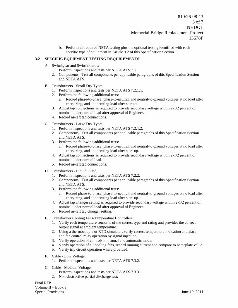
810/26-08-13
3 of 7
NHDOT
Memorial Bridge Replacement Project
13678F
Final RFP
Volume II – Book 3
Special Provisions June 10, 2011
b. Perform all required NETA testing plus the optional testing identified with each
specific type of equipment in Article 3.2 of this Specification Section.
3.2 SPECIFIC EQUIPMENT TESTING REQUIREMENTS
A. Switchgear and Switchboards:
1. Perform inspections and tests per NETA ATS 7.1.
2. Components: Test all components per applicable paragraphs of this Specification Section
and NETA ATS.
B. Transformers - Small Dry Type:
1. Perform inspections and tests per NETA ATS 7.2.1.1.
2. Perform the following additional tests:
a. Record phase-to-phase, phase-to-neutral, and neutral-to-ground voltages at no load after
energizing, and at operating load after startup.
3. Adjust tap connections as required to provide secondary voltage within 2-1/2 percent of
nominal under normal load after approval of Engineer.
4. Record as-left tap connections.
C. Transformers - Large Dry Type:
1. Perform inspections and tests per NETA ATS 7.2.1.2.
2. Components: Test all components per applicable paragraphs of this Specification Section
and NETA ATS.
3. Perform the following additional tests:
a. Record phase-to-phase, phase-to-neutral, and neutral-to-ground voltages at no load after
energizing, and at operating load after start-up.
4. Adjust tap connections as required to provide secondary voltage within 2-1/2 percent of
nominal under normal load.
5. Record as-left tap connections.
D. Transformers - Liquid Filled:
1. Perform inspections and tests per NETA ATS 7.2.2.
2. Components: Test all components per applicable paragraphs of this Specification Section
and NETA ATS.
3. Perform the following additional tests:
a. Record phase-to-phase, phase-to-neutral, and neutral-to-ground voltages at no load after
energizing, and at operating load after start-up.
4. Adjust tap changer setting as required to provide secondary voltage within 2-1/2 percent of
nominal under normal load after approval of Engineer.
5. Record as-left tap changer setting.
E. Transformer Cooling Fans/Temperature Controllers:
1. Verify each temperature sensor is of the correct type and rating and provides the correct
output signal at ambient temperature.
2. Using a thermocouple or RTD simulator, verify correct temperature indication and alarm
and fan control relay operation by signal injection.
3. Verify operation of controls in manual and automatic mode.
4. Verify operation of all cooling fans, record running current and compare to nameplate value.
5. Verify trip circuit operation where provided.
F. Cable - Low Voltage:
1. Perform inspections and tests per NETA ATS 7.3.2.
G. Cable - Medium Voltage:
1. Perform inspections and tests per NETA ATS 7.3.3.
2. Non-destructive partial discharge test:

810/26-08-13
4 of 7
NHDOT
Memorial Bridge Replacement Project
13678F
Final RFP
Volume II – Book 3
Special Provisions June 10, 2011
a. After energization, perform a partial discharge test for baseline data for future partial
discharge maintenance testing.
b. Perform the work while the medium voltage circuits and equipment are energized.
1) The cables shall not be disconnected or de-energized and the testing shall not
expose the cables to voltages that exceed normal operating voltage.
c. Use a frequency domain detection process incorporating a spectrum analyzer with radio
frequency current transformer (RF CT) sensors.
1) The detection system, including spectrum analyzer, RF CT's and interconnecting
cable, shall have a partial discharge detection range that at least covers the
frequency range of 10 kHz to 300 MHz.
2) Testing shall be performed in a manner that complies with the requirements of
IEEE 400 and IEEE 400.3.
H. Cable - Optical Fiber:
1. Perform inspections on tests per TIA/EIA/ANSI 455-78-B, including:
a. Optional time domain reflectometer test.
b. Power attenuation test.
c. Gain margin test.
I. Busway and Busduct:
1. Perform inspections and tests per NETA ATS 7.4.
2. Components: Test all components per applicable paragraphs of this Specification Section
and NETA ATS.
J. Air Interrupter Switches:
1. Perform inspections and tests per NETA ATS 7.5 and NETA ATS 7.6.
2. Components: Test all components per applicable paragraphs of this Specification Section
and NETA ATS.
3. Perform the following optional tests per NETA ATS on all medium voltage switches:
a. Insulation resistance phase-to-phase, phase-to-ground in open and closed positions and
across each open pole.
K. Medium Voltage Source Transfer System;
1. Perform applicable inspections and test per:
a. NETA ATS for Air Interrupter Switches.
b. Manufacturer's instructions.
L. SF6 Insulated Switches:
1. Perform applicable inspections and tests per NETA ATS 7.6.
2. Components: Test all components per applicable paragraphs of this Specification Section
and NETA ATS.
3. Perform the following optional tests per NETA ATS:
a. Insulation resistance phase-to-phase, phase-to-ground in open and closed positions and
across each open pole.
4. Test {low pressure}{low density} alarm circuit.
M. Medium Voltage Circuit Breakers:
1. Perform inspections and tests per NETA ATS 7.6.2.
2. Components: Test all components per applicable paragraphs of this Specification Section
and NETA ATS.
3. Perform the following optional tests per NETA ATS:
a. Control wiring insulation resistance.
b. Minimum trip and close voltage.
c. Overpotential.
4. Perform the following additional tests:

810/26-08-13
5 of 7
NHDOT
Memorial Bridge Replacement Project
13678F
Final RFP
Volume II – Book 3
Special Provisions June 10, 2011
a. High-potential vacuum integrity test per manufacturer’s recommendations.
N. Low Voltage Power Circuit Breakers:
1. Perform inspections and tests per NETA ATS 7.6.1.2.
a. Tests shall include primary current injection testing of all breakers at final settings.
b. Where short-time or instantaneous settings on large frame breakers are beyond the
current capability of field testing, primary injection tests at reduced currents shall be
permitted if combined with secondary injection calibration test of trip unit at final
settings.
2. Components: Test all components per applicable paragraphs of this Specification Section
and NETA ATS.
3. Perform the following additional tests:
a. Shunt trip devices minimum tripping voltage.
4. Record as-left settings.
O. Low Voltage Molded Case Circuit Breakers:
1. Perform inspections and tests per NETA ATS 7.6.1.1.
2. Components:
a. Test all components per applicable paragraphs of this Specification Section and NETA
ATS.
b. Thermal magnetic breakers: Visual and mechanical inspection per NETA ATS only.
c. Solid state trip type: Visual and mechanical inspection and electrical tests per NETA
ATS.
3. Record as-left settings.
P. Network Protectors:
1. Perform inspections and tests per NETA ATS 7.8.
2. Components: Test all components per applicable paragraphs of this Specification Section
and NETA ATS.
3. Perform all tests identified as optional per NETA ATS:
4. Perform the following additional tests:
a. Verify reverse current sensitivity by opening transformer primary switch with feeder
energized and no load on transformer and observing that network protector opens on
magnetizing current alone.
Q. Protective Relays:
1. Perform inspections and tests per NETA ATS 7.9.
a. Tests to be performed using secondary injection of 3 PH current and potential at final
settings.
b. Test at manufacturer’s recommended test points and critical timing points identified on
relay setting sheet.
2. Perform all tests identified as optional per NETA ATS.
3. Perform the following additional tests:
a. Verification of direct trip of associated lockout relay or circuit breaker(s) by using relay
test function or shorting trip contact at relay case.
b. Microprocessor-based relays:
1) Complete commissioning procedure per manufacturer’s instructions, followed by
tests of each relay element at final settings.
2) Verification of all internally-programmed logic.
c. Verification of all auxiliary input and output signals.
d. Verification of power supply/self-diagnostic alarm contact and remote annunciation.
4. Record as-left settings.
R. Instrument Transformers:

810/26-08-13
6 of 7
NHDOT
Memorial Bridge Replacement Project
13678F
Final RFP
Volume II – Book 3
Special Provisions June 10, 2011
1. Perform inspections and tests per NETA ATS 7.10.
2. Components: Test all components per applicable paragraphs of this Specification Section
and NETA ATS.
3. Perform the following optional tests per NETA ATS:
a. Dielectric withstand test on potential transformers.
S. Metering:
1. Perform inspections and tests per NETA ATS 7.11.
2. Components: Test all components per applicable paragraphs of this Specification Section
and NETA ATS.
T. Grounding:
1. Perform inspections and tests per NETA ATS 7.13.
2. Components: Test all components per applicable paragraphs of this Specification Section
and NETA ATS.
U. Ground Fault Protection:
1. Perform inspections and tests per NETA ATS 7.14.
2. Components: Test all components per applicable paragraphs of this Specification Section
and NETA ATS.
3. Perform the following optional tests per NETA ATS:
a. Control wiring insulation resistance.
4. Perform the following additional tests for four-wire systems:
a. Primary current injection into switchgear bus with test set configured to simulate
transformer source and high current jumper used to simulate unbalanced load and
ground fault conditions.
b. Verify no tripping for unbalanced load on each feeder and each main breaker.
c. Verify no tripping for unbalanced load across tie breaker for dual-source schemes.
d. Verify tripping for ground fault on load side of feeder each feeder and on each main
bus.
e. Verify tripping for ground fault on a single feeder and on each main bus through tie
breaker(s) for multiple-source schemes.
V. Motors:
1. Perform inspections and tests per NETA ATS 7.15.
2. See Specification Section 40 05 05.
W. Motor Controllers:
1. Perform inspections and tests per NETA ATS 7.16.
2. Components: Test all components per applicable paragraphs of this Specification Section
and NETA ATS.
X. Generators:
1. Perform inspections and tests per NETA ATS 7.15.2.
2. Components: Test all components per applicable paragraphs of this Specification Section
and NETA ATS.
3. Perform the following additional tests:
a. Load and cycle crank test per Specification Section 26 32 14.
Y. DC Power Systems:
1. Perform inspections and tests per NETA ATS 7.18.
2. Components: Test all components per applicable paragraphs of this Specification Section
and NETA ATS.
3. Perform the following optional tests per NETA ATS:
a. Cell impedance test.
810/26-08-13
7 of 7
NHDOT
Memorial Bridge Replacement Project
13678F
Final RFP
Volume II – Book 3
Special Provisions June 10, 2011
Z. Control System Functional Test:
1. Perform test upon completion of equipment acceptance tests.
2. The test is to prove the correct interaction of all sensing, processing and action devices.
3. Develop a test plan and parameters for the purpose of evaluating the performance of the
system.
4. Perform the following tests:
a. Verify the correct operation of all interlock safety devices for fail-safe functions in
addition to design function.
b. Verify the correct operation of all sensing devices, alarms and indicating devices.
5. Systems to be tested:
END OF SECTION

810/26-09-13
1 of 5
NHDOT
Memorial Bridge Replacement Project
13678F
Final RFP
Volume II – Book 3
Special Provisions June 10, 2011
SECTION 26 09 13
ELECTRICAL METERING DEVICES
PART 1 - GENERAL
1.1 SUMMARY
A. Section Includes:
1. Digital metering equipment.
2. Analog metering equipment.
B. Related Specification Sections include but are not necessarily limited to:
1. New Hampshire Department of Transportation Section 105 - Control of the Work.
2. Section 01 25 13 - Product Substitution.
3. Section 26 05 00 - Electrical: Basic Requirements.
4. Section 26 08 13 - Acceptance Testing.
1.2 QUALITY ASSURANCE
A. Referenced Standards:
1. National Electrical Manufacturers Association (NEMA):
a. 250, Enclosures for Electrical Equipment (1000 Volts Maximum).
2. National Electrical Manufacturers Association/American National Standards Institute
(NEMA/ANSI):
a. C12.20, For Electricity Meter - 0.2 and 0.5 Accuracy Classes.
3. National Fire Protection Association (NFPA):
a. 262, Standard Method of Test for Flame Travel and Smoke of Wires and Cables for
Use in Air-Handling Spaces.
4. Underwriters Laboratories, Inc. (UL):
a. 508, Standard for Safety Industrial Control Equipment.
1.3 SUBMITTALS
A. Shop Drawings:
1. See New Hampshire Department of Transportation Specification Section 105 for
requirements for the mechanics and administration of submittal process.
2. Product technical data including:
a. Provide submittal data for all products specified in PART 2 of this Specification:
b. See Specification Section 26 05 00 for additional requirements.
B. Operation and Maintenance Manuals:
1. See Specification Section 26 05 00 for requirements for:
a. The mechanics and administration of the submittal process.
b. The content of Operation and Maintenance Manuals.
PART 2 - PRODUCTS
2.1 ACCEPTABLE MANUFACTURERS
A. Subject to compliance with the Contract Documents, the following manufacturers are
acceptable:
1. Cutler Hammer.
2. Electro Industries.
3. General Electric Company.

810/26-09-13
2 of 5
NHDOT
Memorial Bridge Replacement Project
13678F
Final RFP
Volume II – Book 3
Special Provisions June 10, 2011
4. Power Measurement.
5. Square D Company.
6. Siemens.
B. Submit request for substitution in accordance with Specification Section 01 25 13.
2.2 DIGITAL METERING DEVICES
A. General:
1. Direct reading metered or calculated values.
2. Microprocessor based.
3. Integral LED or LCD display.
4. Current and potential transformers as required.
5. Integral fusing.
6. Operating temperature: 0 DegF to 150 DegF.
7. Standards:
a. NEMA/ANSI C12.20.
b. UL 508.
B. Type 'A' Low Range Meter:
1. Display the following minimum electrical parameters (accuracy):
a. RMS current per phase (+0.3 percent full scale).
b. RMS voltage line-to-line and line-to-neutral (+0.3 percent full scale).
2. Communication ports and protocols: As specified herein and/or as required for a
functioning system.
3. Supply voltage: 120 Vac.
C. Type 'B' Midrange Meter:
1. Display the following minimum electrical parameters (accuracy):
a. RMS current per phase (+0.3 percent full scale).
b. RMS voltage line-to-line and line-to-neutral (+0.3 percent full scale).
c. Real power (W): 3 PH total (+0.6 percent full scale).
d. Apparent power (VA): 3 PH total (+0.6 percent full scale).
e. Reactive power (VAR): 3 PH total (+0.6 percent full scale).
f. Power factor (+1.0 percent).
g. Frequency (+0.17 percent).
h. Percent current total harmonic distortion (31st).
i. Percent voltage total harmonic distortion (31st).
2. Communication ports and protocols: As specified herein and/or as required for a
functioning system.
3. Supply voltage: 120 Vac.
D. Type 'C' High Range Meter:
1. Display the following minimum electrical parameters (accuracy):
a. RMS current per phase (+0.2 percent full scale).
b. RMS voltage line-to-line and line-to-neutral (+0.2 percent full scale).
c. Real power (W): 3 PH total (+0.4 percent full scale).
d. Apparent power (VA): 3 PH total (+0.4 percent full scale).
e. Reactive power (VAR): 3 PH total (+0.4 percent full scale).
f. Power factor (+1.0 percent).
g. Frequency (+0.04 percent).
h. Percent current individual harmonic and total harmonic distortion (50th).
i. Percent voltage individual harmonic and total harmonic distortion (50th).
j. Watt-hours (0.5 percent).
k. VAR-hours (1.0 percent).

810/26-09-13
3 of 5
NHDOT
Memorial Bridge Replacement Project
13678F
Final RFP
Volume II – Book 3
Special Provisions June 10, 2011
l. VA-hours (0.5 percent).
m. Ampere demand (+0.2 percent full scale).
n. Watt demand (+0.4 percent full scale).
o. VAR demand (+0.4 percent full scale).
p. VA demand (+0.4 percent full scale).
q. Phaser diagram.
2. NEMA/ANSI C12.20, Class 0.2 revenue accuracy.
3. Communication ports and protocols: As specified herein and/or as required for a
functioning system.
4. Supply voltage: 120 Vac.
2.3 ACCESSORIES
A. Personal Computer (PCs) as Operator Interfaces:
1. PCs with the most current hardware and following features:
a. Pentium 4 or Celeron processor.
b. 256 MB RAM.
c. USB, serial and parallel communication ports.
d. 80 GB hard drive.
e. 3 1/2 IN, 1.44 MB diskette drive.
f. CD-ROM drive.
g. Zip backup drive.
h. Video graphics card.
i. Keyboard.
j. Mouse.
k. Monitor:
1) Minimum refresh rate: 75 HZ.
2) Minimum size (nominal/actual viewing): 17 IN/15.6 IN.
3) Automatic and manual degaussing.
4) Resolution: 1280 X 1024 or higher.
5) No glare, flat screen.
6) Adjustable tilt.
7) Maximum dot pitch: 0.28 mm.
8) 256 user selectable colors for displays.
9) Adjustable brightness and contrast.
l. Software: MSWindows operating system.
B. Ink Jet Printers:
1. Rated color print speed: Minimum two (2) pages per minute.
2. Color graphics resolution: At least 720 x 720 dpi.
3. Minimum input tray capacity: 100 sheets.
4. Minimum output tray capacity: 30 sheets.
5. Capable of printing:
a. Letter size paper.
b. Legal size paper.
C. Communication Cable:
1. As recommended by manufacturer.
2. Standard: NFPA 262.
D. Software:
1. Power management and control software.
E. Retrofit Application Enclosure:
1. NEMA 12 rated for indoor locations.

810/26-09-13
4 of 5
NHDOT
Memorial Bridge Replacement Project
13678F
Final RFP
Volume II – Book 3
Special Provisions June 10, 2011
2. NEMA 3R rated for outdoor locations.
3. Hinged front opening door with padlockable latch.
4. Input/output terminal blocks and wiring.
5. Separate control voltage source disconnect switch and wiring.
6. 600 Volt rated power voltage terminal blocks and wiring.
7. Current transformer shorting terminal blocks and wiring.
PART 3 - EXECUTION
3.1 INSTALLATION
A. Install as indicated and in accordance with manufacturer's recommendations and instructions.
1. Provide all equipment as necessary to provide a compete and functioning system.
2. Coordinate with the Owner on final computer screen layouts, trending requirements and
printouts.
B. Meter Types:
1. Type A meters: Not used.
2. Type B meters: .Connected to 480V feeder breakers, unless otherwise indicated on the
Drawings.
3. Type C meters: Connected to 13.8kV breakers and 480V main breakers, unless otherwise
indicated on the Drawings
C. Communication Configuration:
1. Feeder breaker meters shall communicate with its associated main breaker meter.
2. The main breaker meter shall be connected to the nearest plant control system Ethernet
switch.
3. Configure one (1) of the computers provided by the control system with the power
management and control software.
a. Provide technical assistance to the system integrator as necessary to provide a
functioning system.
D. Computer Screen Configuration:
1. Each Type A, B and C meter shall have a data screen with the following minimum data as
applicable for the capabilities of that type of meter:
a. Voltage line-to-line for each phase and an average.
b. Voltage line-to-neutral for each phase and an average.
c. Current for each phase, neutral and average and peak demands.
d. Kilowatts (kW)for each phase, total, demand and peak demand.
e. Kilovolt-amperes (kVA) for each phase, total, demand and peak demand.
f. Kilovolt-amperes reactive (kVAR) for each phase, total, demand and peak demand.
g. Power factor for each phase and total.
h. Frequency.
i. Voltage total harmonic distortion for each phase.
j. Current total harmonic distortion for each phase.
k. Energy (kWhr) for each phase and total.
l. A seven (7) day kW, kVA and kVAR trend average.
m. Peak demands shall be resetable by the operator.
2. Meter Types shall have the following 15 minute trending graphs.
a. Duration: Adjustable, with a seven (7) day default.
b. Phase A current: Minimum, maximum and average.
c. Phase B current: Minimum, maximum and average.
d. Phase C current: Minimum, maximum and average.
e. Neutral current: Minimum, maximum and average.

810/26-09-13
5 of 5
NHDOT
Memorial Bridge Replacement Project
13678F
Final RFP
Volume II – Book 3
Special Provisions June 10, 2011
f. Phase A Watts: Minimum, maximum and average.
g. Phase B Watts: Minimum, maximum and average.
h. Phase C Watts: Minimum, maximum and average.
i. Watts total.
j. Phase A Voltamps: Minimum, maximum and average.
k. Phase B Voltamps: Minimum, maximum and average.
l. Phase C Voltamps: Minimum, maximum and average.
m. Voltamps total.
n. Phase A power factor: Minimum, maximum and average.
o. Phase B power factor: Minimum, maximum and average.
p. Phase C power factor: Minimum, maximum and average.
q. Power factor total.
3.2 FIELD QUALITY CONTROL
A. Acceptance Testing: See Specification Section 26 08 13.
3.3 TRAINING
A. A qualified factory-trained manufacturer's representative shall provide the Owner with 8 HRS of
on-site training in the operation and maintenance of the metering system and its components.
END OF SECTION
810/26-09-16
1 of 9
NHDOT
Memorial Bridge Replacement Project
13678F
Final RFP
Volume II – Book 3
Special Provisions June 10, 2011
SECTION 26 09 16
CONTROL EQUIPMENT ACCESSORIES
PART 1 - GENERAL
1.1 SUMMARY
A. Section Includes:
1. Operator control devices (selector switches, pushbuttons, indicator lights, etc.).
2. Control devices (timers, relays, contactors, etc.).
3. Control panels and operator stations.
B. Related Specification Sections include but are not necessarily limited to:
1. New Hampshire Department of Transportation Section 105 - Control of the Work.
2. Section 01 25 13 - Product Substitution.
3. Section 26 05 00 - Electrical: Basic Requirements.
1.2 QUALITY ASSURANCE
A. Referenced Standards:
1. National Electrical Manufacturers Association (NEMA):
a. 250, Enclosures for Electrical Equipment (1000 Volts Maximum).
b. ICS 2, Industrial Control and System Controllers, Contactors and Overload Relays
Rated 600 Volts.
2. Underwriters Laboratories, Inc. (UL):
a. 508, Standard for Safety Industrial Control Equipment.
b. 508A, Standard for Safety Industrial Control Panels.
B. Miscellaneous:
1. Supplier of Industrial Control Panels shall build control panel under the provisions of
UL 508A.
a. Entire assembly shall be affixed with a UL 508A label "Listed Enclosed Industrial
Control Panel" prior to shipment to the jobsite.
1.3 SUBMITTALS
A. Shop Drawings:
1. See New Hampshire Department of Transportation Specification Section 105 for
requirements for the mechanics and administration of submittal process.
2. Product technical data:
a. Provide submittal data for all products specified in PART 2 of this Specification:
b. Control panel bill of material.
c. See Specification Section 26 05 00 for additional requirements.
3. Fabrication and/or layout drawings.
a. Control panel interior and exterior layout.
b. Control panel wiring diagrams.
B. Operation and Maintenance Manuals:
1. See Specification Section 26 05 00 for requirements for:
a. The mechanics and administration of submittal process.
b. The content of Operation and Maintenance Manuals.

810/26-09-16
2 of 9
NHDOT
Memorial Bridge Replacement Project
13678F
Final RFP
Volume II – Book 3
Special Provisions June 10, 2011
PART 2 - PRODUCTS
2.1 ACCEPTABLE MANUFACTURERS
A. Subject to compliance with the Contract Documents, the following manufacturers are
acceptable:
1. Pilot devices and relays:
a. Idec.
b. Potter & Brumsfield.
c. Time Mark.
d. ATC Diversified Electronics.
2. Contactors:
a. Automatic Switch Company (ASCO).
b. Cutler-Hammer.
c. General Electric Company.
d. Square D Company.
e. Siemens.
f. Allen Bradley.
3. Photocells and time clocks:
a. Grasslin.
b. Tork.
c. Intermatic.
d. Paragon.
4. Alarm devices:
a. Edwards Signaling.
b. Federal Signal Corp.
5. Terminal blocks:
a. Phoenix Contact.
b. Allen-Bradley.
6. Enclosures:
a. Hoffman Engineering Co.
b. Wiegmann.
c. B-Line Circle AW.
d. Adalet.
B. Submit request for substitution in accordance with Specification Section 01 25 13.
2.2 PILOT DEVICES
A. General Requirements:
1. Standards: NEMA ICS 2, UL 508.
2. Heavy-duty NEMA 4/13 watertight/oiltight.
3. Heavy-duty NEMA 4/4X corrosion resistant.
4. Heavy-duty factory sealed, explosion-proof and dust ignition-proof (Class I and II).
5. Mounting hole: 30.5 mm.
6. Contact blocks: 10 amp, NEMA A600 rated, number as required to fulfill functions shown
or specified.
7. Legend plate marked as indicated on Drawings or specified.
B. Selector Switches:
1. Two, three- or four-position rotary switch as required to fulfill functions shown or specified.
2. Maintained contact type.
3. Knob or lever type operators.
C. Pushbuttons:

810/26-09-16
3 of 9
NHDOT
Memorial Bridge Replacement Project
13678F
Final RFP
Volume II – Book 3
Special Provisions June 10, 2011
1. Non-illuminated type:
a. Protective boot.
b. Momentary contact.
c. Standard flush and mushroom operators.
d. Emergency stop pushbuttons: Mushroom head operator and maintained contact.
2. Illuminating type:
a. Protective boot.
b. Momentary contact.
c. Standard flush operator.
d. Serves as both pushbutton control and indicating light.
e. Resistor-type full voltage light unit with lens and panel gasket.
D. Indicating Lights:
1. Allowing replacement of bulb without removal from control panel.
2. Lamp: LED, 120 V or 24 V as required.
3. Full voltage type.
4. Push-to-test indicating lights.
5. Glass lens.
6. Color code lights as follows:
a. Green: OFF or stopped.
b. Amber: Standby; auto mode; ready.
c. Red: ON or running.
2.3 RELAYS
A. General Requirements:
1. Standards: NEMA ICS 2, UL 508.
B. Control Relays:
1. General purpose (ice cube) type:
a. Plug-in housing.
b. Clear polycarbonate dust cover with clip fastener.
c. Coil voltage: 120 Vac or as required.
d. Contacts:
1) 10 amp continuous.
2) Silver cadmium oxide.
3) Minimum of 3 SPDT contacts.
e. Sockets: DIN rail mounted.
f. Internal neon or LED indicator is lit when coil is energized.
g. Manual operator switch.
2. Industrial type:
a. Coil voltage: 120 Vac or as required.
b. Contacts:
1) 10 amp, NEMA A600 rated.
2) Double break, silver alloy.
3) Convertible from normally open to normally closed or vice versa, without
removing any wiring.
4) Expandable from 2 poles to 12 poles.
c. Provide contacts for all required control plus two spares.
C. Time Delay Relays:
1. General purpose type:
a. Timing modes: On and Off delay, interval, one shot and repeat cycle.
b. Plug-in housing.

810/26-09-16
4 of 9
NHDOT
Memorial Bridge Replacement Project
13678F
Final RFP
Volume II – Book 3
Special Provisions June 10, 2011
c. Polycarbonate dust cover with clip fastener.
d. Coil voltage: 120 Vac or as required.
e. Contacts:
1) 10 amp continuous.
2) Silver cadmium oxide.
3) Two normally open and two normally closed DPDT contacts.
f. Sockets: DIN rail mounted.
g. External timing adjustment knob.
h. Timing ranges: 0.05 seconds to 16.65 HRS.
i. Repeat accuracy: +1 percent.
2. Solid State industrial type:
a. Timing modes: On and Off delay and repeat cycle.
b. Industrial housing.
c. Coil voltage: 120 Vac or as required.
d. Contacts:
1) 5 amp, NEMA B150 rated.
2) Silver alloy.
3) Convertible On Delay and Off Delay contacts.
4) One normally open and one normally closed timed contacts.
5) One normally open and one normally closed instantaneous contacts.
e. Furnish with "on" and "timing out" indicators.
f. External timing adjustment knob.
g. Timing ranges: 0.05 seconds to 10 HRS.
h. Repeat accuracy: +1 percent.
3. Mechanical industrial type:
a. Timing modes: On and Off delay.
b. Coil voltage: 120 Vac or as required.
c. Contacts:
1) 10 amp, NEMA A600 rated.
2) Double break, silver alloy.
3) Convertible On Delay and Off Delay contacts.
4) Convertible normally open and normally closed timed contacts.
5) Convertible normally open instantaneous contacts.
d. External timing adjustment knob.
e. Timing ranges: 0.2 - 60 sec or 5 - 180 sec.
f. Repeat accuracy: Greater than +10 percent.
2.4 CONTACTORS
A. General Requirements:
1. Standards: NEMA ICS 2, UL 508.
B. Lighting and Remote Control Switches:
1. Electrically operated, electrically held.{Electrically operated, mechanically held.}
2. Coil voltage: 120 Vac or as required.
3. Contacts: Totally enclosed, double-break silver-cadmium-oxide.
4. Rated for ballasted lighting, tungsten and general use loads.
5. Number of poles, continuous ampere rating and voltage, as indicated on Drawings or as
specified.
6. Auxiliary control relays, as indicated on Drawings or as specified.
7. Auxiliary contacts, as indicated on Drawings or as specified.
C. Definite Purpose:
1. Coil voltage: 120 Vac or as required.

810/26-09-16
5 of 9
NHDOT
Memorial Bridge Replacement Project
13678F
Final RFP
Volume II – Book 3
Special Provisions June 10, 2011
2. Contacts: Totally enclosed, double-break silver-cadmium-oxide.
3. Resistive load and horsepower rated.
4. Number of poles, continuous ampere rating and voltage, as indicated on Drawings or as
specified.
5. Auxiliary contacts, as indicated on Drawings or as specified.
2.5 PHOTOCELLS AND TIME CLOCKS
A. Photocells:
1. Weatherproof enclosure.
2. Adjustable turn-on range, initially set at 1.0 footcandles.
a. Turn-off level approximately three times turn-on.
3. Provide time delay device to eliminate nuisance switching.
4. Voltage, amperage and/or wattage ratings as required for the application.
B. General Requirements for Time Clocks:
1. Separate manual on-off operation without disturbing automatic settings.
2. Enclosure:
a. NEMA 1 for indoor locations.
b. Stand alone or DIN rail for mounting in control panel.
c. NEMA 3R or 4 for exterior locations.
3. Voltage, amperage and/or wattage ratings as required for the application.
C. Electromechanical:
1. 24 HR dial powered by a self-starting synchronous motor.
2. Minimum of 16 HR carryover power utilizing a spring-driven reserve with automatic
rewind or rechargeable battery.
3. Minimum of 12 pairs of on-off trippers and a skip-a-day device.
D. Electromechanical:
1. Seven (7) day dial powered by a self-starting synchronous motor.
2. Minimum of 24 HR carryover power utilizing a spring-driven reserve with automatic
rewind or rechargeable battery.
3. Minimum of one (1) pair of on-off trippers per day.
E. Electronic:
1. 24 HR and seven (7) day programmable using solid state technology.
2. Minimum of 72 HR carryover power utilizing rechargeable battery or capacitor.
3. Minimum of seven (7) on and seven (7) off set points.
F. Electronic:
1. 365 day programmable using solid state technology with block programming.
2. Minimum of 72 HR carryover power utilizing rechargeable battery or capacitor.
3. Minimum of 48 events per week, 16 individual holiday overrides, daylight savings or
standard time selectable, automatic leap year correction.
G. Astronomical Clocks:
1. Adjustable for the installed latitude.
a. Settings for astro on/astro off, astro on/time off or time on/astro off.
2. 365 day programmable using solid state technology with block programming.
3. Minimum of 72 HR carryover power utilizing rechargeable battery or capacitor.
4. Minimum of 48 events per week, 16 individual holiday overrides daylight savings or
standard time selectable, automatic leap year correction.
2.6 ALARM DEVICES
A. Alarm Horns:

810/26-09-16
6 of 9
NHDOT
Memorial Bridge Replacement Project
13678F
Final RFP
Volume II – Book 3
Special Provisions June 10, 2011
1. Vibrating horn type.
2. PLC compatible as required.
3. Heavy-duty die cast housing with corrosion resistant finish.
4. Adjustable volume: 78 to 103 dB at 10 FT.
5. Voltage: 120 Vac or as required.
6. Enclosures/mountings:
a. Flush wall or panel mounting in dry areas.
b. NEMA 4X panel mounting in wet areas.
c. Surface mounting in dry areas.
d. NEMA 4X surface mounting in wet areas.
e. NEMA 4X, hazardous location surface mounting in wet and hazardous areas.
1) Fixed volume: 97 dB at 10 FT.
B. Alarm Lights:
1. Panel mounted:
a. Strobe type.
b. Shatter resistant polycarbonate lens and base.
c. Lens color as indicated on Drawings.
d. NEMA 4X enclosure.
e. PLC compatible.
f. Voltage: 120 Vac.
2. Wall mounted:
a. Heavy-duty strobe type.
b. Weatherproof shatter resistant polycarbonate lens and cast base.
c. Optically designed fresnel lens with color as indicated on Drawings.
d. Immune to shock and vibration, no moving parts.
e. Xenon flash tube providing a minimum of 65 single flashes per minute.
f. Mounting: Wall or corner wall brackets.
3. Hazardous and corrosive locations:
a. Heavy-duty strobe type.
b. Weatherproof and rated for the indicated hazardous location.
c. Body: Zinc plated cast iron or cast copper free aluminum and/or coated with 20 mils of
PVC.
d. High impact glass dome with guard.
e. Shatter resistant polycarbonate lens with color as indicated on Drawings.
f. Immune to shock and vibration, no moving parts.
g. Xenon flash tube providing a minimum of 65 single flashes per minute.
h. Mounting: Wall bracket or pendant.
2.7 MISCELLANEOUS DEVICES
A. Run Time Meters:
1. Six-digit wheels including a 1/10 digit.
2. Non-reset type.
3. Time range in hours.
4. Automatic recycle at zero.
5. Accuracy: 1 percent.
6. Sealed against dirt and moisture.
7. Tamperproof.
2.8 TERMINATION EQUIPMENT
A. General Requirements:
1. Modular type with screw compression clamp.

810/26-09-16
7 of 9
NHDOT
Memorial Bridge Replacement Project
13678F
Final RFP
Volume II – Book 3
Special Provisions June 10, 2011
2. Screws: Stainless steel.
3. Current bar: Nickel-plated copper alloy.
4. Thermoplastic insulation rated for -40 to +90 DegC.
5. Wire insertion area: Funnel-shaped to guide all conductor strands into terminal.
6. End sections and end stops at each end of terminal strip.
7. Machine-printed terminal markers on both sides of block.
8. Spacing: 6 mm.
9. Wire size: 22-12 AWG.
10. Rated voltage: 600 V.
11. DIN rail mounting.
B. Standard-type block:
1. Rated current: 30 A.
2. Color: Gray body.
C. Bladed-type disconnect block:
1. Terminal block with knife blade disconnect which connects or isolated the two sides of the
block.
2. Rated current: 10 A.
3. Color:
a. Panel control voltage leaves enclosure - normal: Gray body, orange switch.
b. Foreign voltage entering enclosure: Orange body, orange switch.
D. Grounded-type block:
1. Electrically grounded to mounting rail.
2. Terminal ground wires and analog cable shields.
3. Color: Green and yellow body.
E. Fuse Holders:
1. Blocks can be ganged for multi-pole operation.
2. Spacing: 9.1 mm.
3. Wire size: 30-12 AWG.
4. Rated voltage: 300 V.
5. Rated current: 12 A.
6. Fuse size: 1/4 x 1-1/4.
7. Blown fuse indication.
8. DIN rail mounting.
2.9 ENCLOSURES
A. Control Panels:
1. NEMA 4 rated:
a. Seams continuously welded and ground smooth.
b. No knockouts.
c. External mounting flanges.
d. Hinged or non-hinged cover held closed with stainless steel screws and clamps.
e. Cover with oil resistant gasket.
2. NEMA 4X rated:
a. Body and cover: 14 GA Type 304 or 316 stainless steel.
b. Seams continuously welded and ground smooth.
c. No knockouts.
d. External mounting flanges.
e. Hinged door and stainless steel screws and clamps.
f. Door with oil-resistant gasket.
3. NEMA 7 and 9 rated:
810/26-09-16
8 of 9
NHDOT
Memorial Bridge Replacement Project
13678F
Final RFP
Volume II – Book 3
Special Provisions June 10, 2011
a. Cast gray iron alloy or copper-free aluminum.
b. Drilled and tapped openings or tapered threaded hub.
c. Cover bolted-down with stainless steel bolts or threaded cover with neoprene gasket.
d. External mounting flanges.
e. Grounding lug.
f. Accessories: 40 mil PVC exterior coating and 2 mil urethane interior coating.
4. NEMA 12 enclosure:
a. Body and cover: 14 GA steel finished with rust inhibiting primer and manufacturers
standard paint inside and out.
b. No knockouts.
c. External mounting flanges.
d. Non-hinged stainless steel cover held closed with captivated cover screws threaded into
sealed wells or hinged cover held closed with stainless steel screws and clamps.
e. Flat door with oil resistant gasket.
5. Control panel miscellaneous accessories:
a. Back plane mounting panels: Steel with white enamel finish or Type 304 stainless
steel.
b. Interiors shall be white or light gray in color.
c. Wire management duct:
1) Bodies: PVC with side holes.
2) Cover: PVC snap-on.
3) Size as required.
d. Rigid handles for covers larger than 9 SF or heavier than 25 LBS.
e. Split covers when heavier than 25 LBS.
f. Floor stand kits made of same material as the enclosure.
g. Weldnuts for mounting optional panels and terminal kits.
h. Ground bonding jumper from door, across hinge, to enclosure body.
6. Standards: NEMA 250, UL 508.
B. Operator Control Stations:
1. NEMA 4/13 rated:
a. Die cast aluminum body with manufacturers standard finish.
b. Gasketed die cast aluminum cover with manufacturers standard finish.
c. Number of device mounting holes as required.
2. NEMA 4X rated:
a. Type 304 or 316 stainless steel body.
b. Gasketed Type 304 or 316 stainless steel cover.
c. Number of device mounting holes as required.
3. NEMA 7 and 9 rated:
a. Zinc plated cast iron or die-cast copper free aluminum, with threaded hubs, grounding
screw and with manufacturers standard finish.
b. "EDS" or "EFS" style.
c. Single or multiple gang or tandem.
d. Accessories: 40 mil PVC exterior coating and two (2) mil urethane interior coating.
2.10 MAINTENANCE MATERIALS
A. Provide 100 percent replacement lamps for indicating lights.
B. Provide 10 percent replacement caps for indicating lights.
810/26-09-16
9 of 9
NHDOT
Memorial Bridge Replacement Project
13678F
Final RFP
Volume II – Book 3
Special Provisions June 10, 2011
PART 3 - EXECUTION
3.1 INSTALLATION
A. Install as indicated and in accordance with manufacturer's recommendations and instructions.
B. Control Panels:
1. Size as required to mount the equipment.
2. Permitted uses of NEMA 4 enclosure:
a. Surface mounted in areas designated as wet.
3. Permitted uses of NEMA 4X enclosure:
a. Surface mounted in areas designated as wet and/or corrosive or highly corrosive.
4. Permitted uses of NEMA 7 enclosure:
a. Surface mounted in areas designated as Class I hazardous.
5. Permitted uses of NEMA 12 enclosure:
a. Surface mounted in areas designated as dry and/or dusty architecturally or non-
architecturally finished areas.
C. Operator Control Stations:
1. Permitted uses of NEMA 4/13 enclosure:
a. Surface mounted in areas designated as dry and/or dusty architecturally or non-
architecturally finished areas and wet.
2. Permitted uses of NEMA 4X enclosure:
a. Surface mounted in areas designated as wet and/or corrosive or highly corrosive.
3. Permitted uses of NEMA 7 enclosure:
a. Surface mounted in areas designated as Class I hazardous with PVC coating in
corrosive and highly corrosive areas when PVC coated conduit is used.
3.2 FIELD QUALITY CONTROL
A. See Specification Section 26 05 00.
END OF SECTION

810/26-12-19
1 of 4
NHDOT
Memorial Bridge Replacement Project
13678F
Final RFP
Volume II – Book 3
Special Provisions June 10, 2011
SECTION 26 12 19
DISTRIBUTION TRANSFORMERS
PART 1 - GENERAL
1.1 SUMMARY
A. Section Includes:
1. Distribution pad-mounted transformers.
B. Related Specification Sections include but are not necessarily limited to:
1. New Hampshire Department of Transportation Section 105 - Control of the Work.
2. Section 01 25 13 - Product Substitution.
3. Section 26 05 00 - Electrical: Basic Requirements.
4. Section 26 08 13 - Acceptance Testing.
1.2 QUALITY ASSURANCE
A. Referenced Standards:
1. American National Standards Institute (ANSI).
2. Institute of Electronic and Electronics Engineers, Inc. (IEEE):
a. 386, Standard for Separable Insulated Connector Systems for Power Distribution
Systems Above 600 V.
b. C57.12.00, Standard General Requirements for Liquid-Immersed Distribution, Power,
and Regulating Transformers.
c. C57.12.34, Standard Requirements for Pad-Mounted, Compartmental-Type, Self-
Cooled, Three-Phase Distribution Transformers (2500 kVa and Smaller) - High-
Voltage: 34 500 GrdY/19 920 Volts and Below; Low-Voltage: 480 Volts and Below.
d. C57.12.70, Standard Terminal Markings and Connections for Distribution and Power
Transformers.
e. C57.12.80, Standard Terminology for Power and Distribution Transformers.
f. C57.12.90, Standard Test Code for Liquid-Immersed Distribution, Power, and
Regulating Transformers.
g. C62.11, Standard for Metal-Oxide Surge Arresters for Alternating Current Power
Circuits (>1 kV).
3. National Electrical Manufacturers Association (NEMA).
1.3 SUBMITTALS
A. Shop Drawings:
1. See New Hampshire Department of Transportation Specification Section 105 for
requirements for the mechanics and administration of submittal process.
2. Product technical data:
a. Provide submittal data for all products specified in PART 2 of this Specification
Section.
b. See Specification Section 26 05 00 for additional requirements.
3. Fabrication and/or layout drawings.
a. Nameplate drawing.
4. Test reports:
a. Factory tests.
B. Operation and Maintenance Manuals:
1. See Specification Section 26 05 00 for requirements for:
a. The mechanics and administration of the submittal process.

810/26-12-19
2 of 4
NHDOT
Memorial Bridge Replacement Project
13678F
Final RFP
Volume II – Book 3
Special Provisions June 10, 2011
b. The content of Operation and Maintenance Manuals.
PART 2 - PRODUCTS
2.1 ACCEPTABLE MANUFACTURERS
A. Subject to compliance with the Contract Documents, the following manufacturers are
acceptable:
1. ABB.
2. Cooper Power Systems.
3. General Electric Company.
4. Square D Company.
5. Cutler Hammer.
B. Submit request for substitution in accordance with Specification Section 01 25 13.
2.2 THREE-PHASE TRANSFORMER
A. General:
1. Transformer to be designed and constructed in accordance with:
a. IEEE C57.12.00, IEEE C57.12.34, IEEE C57.12.70, IEEE C57.12.80.
B. Ratings:
1. Type: Outdoor, pad-mounted, liquid-immersed, self-cooled, compartmental type.
2. Operation and application: Step-down operation.
3. Configuration:
a. Dead-front, loop-feed primary.
4. Voltage and kVA Ratings: As specified on the Drawings.
5. Number of phases: Three (3).
6. Frequency: 60 Hz.
7. Polarity: ANSI standard.
8. Percent impedance: ANSI standard.
9. Basic impulse level (BIL): As indicated on the plans.
10. Temperature rise: 65 DegC.
11. Connections:
a. Delta or Wye: As indicated on the Drawings.
b. Primary: {200 ampere bushing wells and insert for loadbreak elbows.}{600 ampere
one-piece bushing/well for deadbreak elbows.}
c. Secondary:
1) Less than 750 kVA: Six-hole, spade-type minimum or as required.
2) 750 kVA and greater: 12-hole, spade-type minimum or as required.
12. Tap-changer: De-energized type on H-winding, five (5) total with:
a. Two (2)2.5 percent above and two (2) 2.5 percent below nominal tap.
13. Sectionalizing oil immersed load break primary switch:
a. Two (2) position, with the switch positions labeled:
1) "XFMR OPEN" when the coil is de-energized.
2) "XFMR CLOSED" when the coil is energized.
b. Four (4) position, 'V' blade, with the switch positions labeled:
1) "SOURCE A" (Loop is open and the coil is energized by Source A).
2) "SOURCE B" (Loop is open and the coil is energized by Source B).
3) "SOURCE A & B" (Loop is closed and the coil is energized by both sources).
4) "LOOP & XFMR OPEN" (Loop is open and the coil is de-energized).
c. Four (4) position, 'T' blade, with the switch positions labeled:
1) "SOURCE A" (Loop is open and the coil is energized by Source A).

810/26-12-19
3 of 4
NHDOT
Memorial Bridge Replacement Project
13678F
Final RFP
Volume II – Book 3
Special Provisions June 10, 2011
2) "SOURCE B" (Loop is open and the coil is energized by Source B).
3) "SOURCE A & B" (Loop is closed and the coil is energized by both sources).
4) "LOOP CLOSED & XFMR OPEN" (Loop is closed and the coil is de-energized).
C. Components:
1. Windings: Aluminum or copper.
2. Tank:
a. Sealed-tank construction with welded main cover and bolted tamper-resistant handhole.
b. Steel divider between high-voltage and low-voltage compartments.
c. No exposed screws, bolts, or other fastening devices that are externally removable.
d. No openings through which foreign objects such as sticks, rods, or wires may contact
live parts.
e. 24 IN deep cabinet (minimum)
f. 1 IN upper fill plug.
g. 1 IN drain valve with sampling device.
h. Automatic pressure relief device.
i. Stainless steel NEMA 2-hole ground pads.
3. Door:
a. Each compartment will have removable, three-point latching hinged doors equipped for
latching in the open position.
b. The high-voltage compartment door will have a fastening device that is accessible only
through the low-voltage compartment.
c. The hinge assemblies made of corrosion-resistant material.
1) Provide stainless-steel hinge pins of 3/8 IN minimum diameter.
d. Both compartment doors capable of securing with a single padlock having a maximum
1/2 IN DIA shackle.
4. Unit protection:
a. Provide unit protection with a partial-range current limiting fuse on each primary phase
(under oil, factory replaceable only).
b. Provide an expulsion-type, bayonet fuse (under oil, user serviceable) in series with the
current limiting fuse.
5. Finish:
a. Manufacturer's standard corrosion protection system.
b. Dark "padmount" green.
6. Insulating oil:
a. Less Flammable liquid.
b. Permanently affix nameplate to outside of tank stamped "Non PCB".
7. Accessories:
a. Liquid level indication.
b. Dial-type thermometer.
c. Provisions for pressure vacuum gage.
d. Stainless steel or laser-scribed anodized aluminum nameplate, with date of
manufacturer.
2.3 SURGE ARRESTORS
A. Standards: IEEE 386 and IEEE C62.11.
B. MOV gapless elbow type.
C. Elbow Connector:
1. One-piece design, comprised of an insulation layer and outer shield constructed of EPDM
rubber.
2. 200A, dead front, load break type with hot stick pulling eye and grounding tab.

810/26-12-19
4 of 4
NHDOT
Memorial Bridge Replacement Project
13678F
Final RFP
Volume II – Book 3
Special Provisions June 10, 2011
D. Voltage Class: As indicated on the Drawings.
E. Arrestor MCOV Rating: As indicated on the Drawings.
2.4 SOURCE QUALITY CONTROL
A. Factory Tests: Test transformers in accordance with IEEE C57.12.90.
2.5 MAINTENANCE MATERIALS
A. Touch-up paint, two (2) separate one (1) quart containers.
PART 3 - EXECUTION
3.1 INSTALLATION
A. Install on pad as detailed on the Drawings and in accordance with manufacture's instructions.
B. Transformer locations as shown on the Drawings are intended to be used as a guide.
1. Field conditions may affect actual transformer location.
2. Coordinate final location with Owner.
C. Install three-phase transformers on concrete pad per detail on the Drawings.
3.2 FIELD QUALITY CONTROL
A. Acceptance Testing: See Specification Section 26 08 13.
END OF SECTION

810/26-22-13
1 of 3
NHDOT
Memorial Bridge Replacement Project
13678F
Final RFP
Volume II – Book 3
Special Provisions June 10, 2011
SECTION 26 22 13
DRY-TYPE TRANSFORMERS
PART 1 - GENERAL
1.1 SUMMARY
A. Section Includes:
1. Dry-type transformers, 1000 kVA and less.
B. Related Specification Sections include but are not necessarily limited to:
1. New Hampshire Department of Transportation Section 105 - Control of the Work.
2. Section 01 25 13 - Product Substitution.
3. Section 26 05 00 - Electrical: Basic Requirements.
4. Section 26 05 26 - Grounding.
1.2 QUALITY ASSURANCE
A. Referenced Standards:
1. Institute of Electrical and Electronics Engineers, Inc. (IEEE):
a. C57.96, Guide for Loading Dry-Type Distribution and Power Transformers.
2. National Electrical Manufacturers Association (NEMA):
a. 250, Enclosures for Electrical Equipment (1000 Volts Maximum).
b. ST 20, Dry-Type Transformers for General Applications.
c. TP 1, Guide for Determining Energy Efficiency for Distribution Transformers.
3. Underwriters Laboratories, Inc. (UL):
a. 506, Standard for Safety Specialty Transformers.
b. 1561, Standard for Safety Dry-Type General Purpose and Power Transformers.
1.3 SUBMITTALS
A. Shop Drawings:
1. See New Hampshire Department of Transportation Specification Section 105 for
requirements for the mechanics and administration of submittal process.
2. Product technical data:
a. Provide submittal data for all products specified in PART 2 of this Specification:
b. See Specification Section 26 05 00 for additional requirements.
3. Fabrication and/or layout drawings.
a. Nameplate drawing.
4. Certifications:
a. Sound level certifications.
B. Operation and Maintenance Manuals:
1. See Specification Section 26 05 00 for:
a. The mechanics and administration of the submittal process.
b. The content of Operation and Maintenance Manuals.
PART 2 - PRODUCTS
2.1 ACCEPTABLE MANUFACTURERS
A. Subject to compliance with the Contract Documents, the following manufacturers are
acceptable:

810/26-22-13
2 of 3
NHDOT
Memorial Bridge Replacement Project
13678F
Final RFP
Volume II – Book 3
Special Provisions June 10, 2011
1. Cutler-Hammer.
2. General Electric Company.
3. Square D Company.
4. Siemens.
5. Sola/Hevi-Duty.
B. Submit request for substitution in accordance with Specification Section 01 25 13.
2.2 GENERAL PURPOSE DRY-TYPE TRANSFORMERS
A. Ventilated or non-ventilated, air cooled, two (2) winding type.
B. Cores:
1. High grade, non-aging silicon steel with high magnetic permeability, and low hysteresis and
eddy current losses.
2. Magnetic flux densities are to be kept well below the saturation point.
C. Coils: Continuous wound with electrical grade aluminum.
D. Ventilated Units:
1. Core and coils assembly impregnated with non-hygroscopic, thermosetting varnish and
cured to reduce hot spots and seal out moisture and completely isolated from the enclosure
by means of vibration dampening pads.
2. Dripproof, NEMA 1, steel enclosure finished with a weather-resistant enamel and
ventilation openings protected from falling dirt.
E. Furnish Taps for Transformers as follows:
1. 1 PH, 2 kVA and below: None.
2. 1 PH, 3 to 25 kVA: Two (2) 5 percent FCBN.
3. 1 PH, 25 kVA and above: Two (2) 2.5 percent FCAN and four (4) 2.5 percent FCBN.
4. 3 PH, 3 to 15 kVA: Two (2) 5 percent FCBN.
5. 3 PH, 15 kVA and above: Two (2) 2.5 percent FCAN and four (4) 2.5 percent FCBN.
F. Sound Levels:
1. Manufacturer shall guarantee not to exceed the following:
a. Up to 9 kVA: 40 dB.
b. 10 to 50 kVA: 45 dB.
c. 51 to 150 kVA: 50 dB.
d. 151 to 300 kVA: 55 dB.
G. Efficiency:
1. Ventilated, 15 kVA and larger: Energy efficient meeting NEMA TP 1 requirements.
H. Insulating Material (600 V and below):
1. 3 to 15 kVA units: 185 DegC insulation system with a 115 DegC rise.
2. 15 kVA and above units: 220 DegC insulation system with a 150 DegC rise.
I. Ratings: 60 Hz, voltage, KVA and phase, as indicated on the Drawings.
J. Finish: Rust inhibited primer and manufacturers standard paint inside and out.
K. Standards: IEEE C57.96, NEMA ST 20, NEMA TP 1, UL 506, UL 1561.
PART 3 - EXECUTION
3.1 INSTALLATION
A. Install products in accordance with manufacturer's instructions.

810/26-22-13
3 of 3
NHDOT
Memorial Bridge Replacement Project
13678F
Final RFP
Volume II – Book 3
Special Provisions June 10, 2011
B. Indoor Locations:
1. Provide ventilated type for 15 kVA units and above.
2. Provide non-ventilated type for 9 kVA units and below and were indicated on the Drawings.
3. Mount 9 kVA units and below on wall.
4. Mount 15 kVA units and above on chamfered 4 IN high concrete housekeeping pad or from
wall and/or ceiling, at 7 FT above finished floor, using equipment support brackets per
Specification Section 26 05 00.
5. Provide rubber vibrations isolation pads.
C. Enclosures: Painted steel in all areas except stainless steel in highly corrosive areas.
D. Ground in accordance with Specification Section 26 05 26.
END OF SECTION

810/26-24-16
1 of 3
NHDOT
Memorial Bridge Replacement Project
13678F
Final RFP
Volume II – Book 3
Special Provisions June 10, 2011
SECTION 26 24 16
PANELBOARDS
PART 1 - GENERAL
1.1 SUMMARY
A. Section Includes:
1. Lighting and appliance panelboards.
2. Power distribution panelboards.
3. Panelboards mounted in Motor Control Centers.
B. Related Specification Sections include but are not necessarily limited to:
1. New Hampshire Department of Transportation Section 105 - Control of the Work.
2. Section 01 25 13 - Product Substitution.
3. Section 26 05 00 - Electrical: Basic Requirements.
4. Section 26 28 00 - Overcurrent and Short Circuit Protective Devices.
1.2 QUALITY ASSURANCE
A. Referenced Standards:
1. National Electrical Manufacturers Association (NEMA):
a. 250, Enclosures for Electrical Equipment (1000 Volts Maximum).
b. PB 1, Panelboards.
2. National Fire Protection Association (NFPA):
a. 70, National Electrical Code (NEC).
3. Underwriters Laboratories, Inc. (UL):
a. 50, Enclosures for Electrical Equipment, Non-Environmental Considerations.
b. 67, Standard for Panelboards.
1.3 SUBMITTALS
A. Shop Drawings:
1. See New Hampshire Department of Transportation Specification Section 105 for
requirements for the mechanics and administration of submittal process.
2. Product technical data.
a. Provide submittal data for all products specified in PART 2 of this Specification
Section.
b. See Specification Section 26 05 00 for additional requirements.
3. Fabrication and/or layout drawings:
a. Panelboard layout with alphanumeric designation, branch circuit breakers size and type,
as indicated in the panelboard schedules.
B. Operation and Maintenance Manuals:
1. See Specification Section 26 05 00 for requirements for:
a. The mechanics and administration of the submittal process.
b. The content of Operations and Maintenance Manuals.
2. Panelboard schedules with as-built conditions.

810/26-24-16
2 of 3
NHDOT
Memorial Bridge Replacement Project
13678F
Final RFP
Volume II – Book 3
Special Provisions June 10, 2011
PART 2 - PRODUCTS
2.1 ACCEPTABLE MANUFACTURERS
A. Subject to compliance with the Contract Documents, the following manufacturers are
acceptable:
1. Cutler-Hammer.
2. General Electric Company.
3. Square D Company.
4. Siemens.
B. Submit request for substitution in accordance with Specification Section 01 25 13.
2.2 MANUFACTURED UNITS
A. Standards: NEMA PB 1, NFPA 70, UL 50, UL 67.
B. Ratings:
1. Current, voltage, number of phases, number of wires as indicated on the Drawings.
2. Panelboards rated 240 Vac or less: 10,000 amp minimum short circuit rating or as indicated
in the schedule.
3. Panelboards rated 480 Vac: 14,000 amp minimum short circuit rating or as indicated in the
schedule.
4. Service Entrance Equipment rated when indicated on the Drawings.
C. Construction:
1. Interiors factory assembled and designed such that switching and protective devices can be
replaced without disturbing adjacent units and without removing the main bus connectors.
2. Multi-section panelboards: Feed-through or sub-feed lugs.
3. Main lugs: Solderless type approved for copper and aluminum wire.
D. Bus Bars:
1. Main bus bars:
a. Plated aluminum or copper sized to limit temperature rise to a maximum of 65 DegC
above an ambient of 40 DegC.
b. Drilled and tapped and arranged for sequence phasing of the branch circuit devices.
2. Ground bus and isolated ground bus, when indicated on the Drawings: Solderless
mechanical type connectors.
3. Neutral bus bars: Insulated 100 percent rated or 200 percent rated, when indicated on the
Drawings and with solderless mechanical type connectors.
E. Enclosure:
1. Boxes: Code gage galvanized steel, furnish without knockouts.
2. Trim assembly: Code gage steel finished with rust inhibited primer and manufacturers
standard paint inside and out.
3. Lighting and appliance panelboard:
a. Trims supplied with hinged door over all circuit breaker handles.
b. Trims for surface mounted panelboards, same size as box.
c. Trims for flush mounted panelboards, overlap the box by 3/4 IN on all sides.
d. Doors lockable with corrosion resistant chrome-plated combination lock and catch, all
locks keyed alike.
e. Nominal 20 IN wide and 5-3/4 IN deep with gutter space in accordance with NFPA 70.
f. Clear plastic cover for directory card mounted on the inside of each door.
g. NEMA 3R or NEMA 12 rated: Door gasketed.
4. Power distribution panelboard:
a. Trims cover all live parts with switching device handles accessible.
810/26-24-16
3 of 3
NHDOT
Memorial Bridge Replacement Project
13678F
Final RFP
Volume II – Book 3
Special Provisions June 10, 2011
b. Less than or equal to 12 IN deep with gutter space in accordance with NFPA 70.
c. Clear plastic cover for directory card mounted front of enclosure.
d. NEMA 3R or NEMA 12 rated: Doors gasketed and lockable with corrosion resistant
chrome-plated combination lock and catch, all locks keyed alike.
F. Overcurrent and Short Circuit Protective Devices:
1. Main overcurrent protective device:
a. Molded case circuit breaker.
2. Branch overcurrent protective devices:
a. Mounted molded case circuit breaker.
3. See Specification Section 26 28 00 for overcurrent and short circuit protective device
requirements.
4. Factory installed.
PART 3 - EXECUTION
3.1 INSTALLATION
A. Install as indicated on the Drawings, in accordance with the NFPA 70, and in accordance with
manufacturer's instructions.
B. Support panelboard enclosures from wall studs or modular channels support structure, per
Specification Section 26 05 00.
C. Provide NEMA 1, NEMA 3R or NEMA 12 rated enclosure as indicated on the Drawings.
D. Provide each panelboard with a typed directory:
1. Identify all circuit locations in each panelboard with the load type and location served.
2. Mechanical equipment shall be identified by Owner-furnished designation if different than
designation indicated on the Drawings.
3. Room names and numbers shall be final building room names and numbers as identified by
the Owner if different than designation indicated on the Drawings.
END OF SECTION

810/26-24-19
1 of 8
NHDOT
Memorial Bridge Replacement Project
13678F
Final RFP
Volume II – Book 3
Special Provisions June 10, 2011
SECTION 26 24 19
MOTOR CONTROL EQUIPMENT
PART 1 - GENERAL
1.1 SUMMARY
A. Section Includes:
1. Motor control centers.
2. Separately mounted motor starters (including those supplied with equipment).
3. Manual motor starters.
B. Related Specification Sections include but are not necessarily limited to:
1. New Hampshire Department of Transportation Section 105 - Control of the Work.
2. Section 01 25 13 - Product Substitution.
3. Section 26 05 00 - Electrical: Basic Requirements.
4. {Section 26 08 13 - Acceptance Testing.}
5. Section 26 29 23 - Variable Frequency Drives - Low Voltage.
6. Section 26 28 00 - Overcurrent and Short Circuit Protective Devices.
7. Section 26 43 13 - Low Voltage Surge Protective Devices (SPD).
8. Section 26 09 13 - Electrical Metering Devices.
9. Section 26 09 16 - Control Equipment Accessories.
1.2 QUALITY ASSURANCE
A. Referenced Standards:
1. International Electrotechnical Commission (IEC).
2. National Electrical Manufacturers Association (NEMA):
a. 250, Enclosures for Electrical Equipment (1000 Volt Maximum).
b. ICS 2, Controllers, Contactors and Overload Relays Rated 600 V.
c. ICS 3, Medium-Voltage Controllers Rated 2001 to 7200 V AC.
3. Underwriters Laboratories, Inc. (UL):
a. 508, Standard for Industrial Control Equipment.
b. 845, Motor Control Centers.
B. Miscellaneous:
1. Verify motor horsepower loads, other equipment loads, and controls from approved shop
drawings and notify Engineer of any discrepancies.
2. Verify the required instrumentation and control wiring for a complete system and notify
Engineer of any discrepancies.
1.3 SUBMITTALS
A. Shop Drawings:
1. See New Hampshire Department of Transportation Specification Section 105 for
requirements for the mechanics and administration of submittal process.
2. Product technical data:
a. Provide submittal data for all products specified in PART 2 of this Specification
Section.
b. See Specification Section 26 05 00 for additional requirements.
3. Fabrication and/or layout drawings:
a. Motor control center:

810/26-24-19
2 of 8
NHDOT
Memorial Bridge Replacement Project
13678F
Final RFP
Volume II – Book 3
Special Provisions June 10, 2011
1) Elevation drawing with overall dimensions.
2) Starter and component schedule.
3) Identification of units and their location in the MCC.
4) Location of incoming line terminals.
5) Mounting dimensions.
6) Available conduit entrance areas.
7) Nameplate schedule.
8) Assembly ratings (amps, volts, short circuit, etc.).
9) Unit ladder logic wiring for each unit depicting electrical interlocking and wiring
between units (NEMA ICS 3 Class II) and identification of terminals where field
devices or remote control signals are to be terminated (NEMA ICS 3 Class II-S) as
indicated on the Drawings and/or loop descriptions.
b. Separately mounted combination starters:
1) Unit ladder logic wiring for each unit depicting electrical wiring and identification
of terminals where field devices or remote control signals are to be terminated as
indicated on the Drawings and/or loop descriptions.
B. Operation and Maintenance Manuals:
1. See Specification Section 26 05 00 for requirements for:
a. The mechanics and administration of the submittal process.
b. The content of Operation and Maintenance Manuals.
c. Fabrication and/or layout drawings updated with as-built conditions.
PART 2 - PRODUCTS
2.1 ACCEPTABLE MANUFACTURERS
A. Subject to compliance with the Contract Documents, the following manufacturers are
acceptable:
1. Allen-Bradley.
2. Cutler Hammer.
3. General Electric Company.
4. Square D Company.
5. Siemens.
B. Submit request for substitution in accordance with Specification Section 01 25 13.
2.2 MOTOR CONTROL CENTERS
A. Ratings:
1. 600 V class, 3 PH, 60 Hz with operating voltage and number of wires as indicated on the
Drawings.
2. Assembly short circuit current and interrupting device rating as indicated on the Drawings.
3. Service Entrance Equipment rated when indicated on the Drawings.
B. Construction:
1. Standards: UL 845.
2. Totally enclosed, dead front, free standing assemblies, bolted together to form a single
assembly.
3. Fabricate of not less than 14 GA steel with 16 GA steel doors in standardized units.
4. Nominal size per section: 20 IN wide, 20 or 21 IN deep, and 90 IN high.
5. Enclosure:
a. NEMA 1 gasketed.

810/26-24-19
3 of 8
NHDOT
Memorial Bridge Replacement Project
13678F
Final RFP
Volume II – Book 3
Special Provisions June 10, 2011
b. NEMA 12:
1) Dust-tight and drip-proof.
2) Gasketed material round all doors, door cutouts, cover plates, side, top and back
sheets.
3) Gasketed bottom plate.
c. NEMA 3R non-walk-in:
1) Rainproof and sleet resistant.
2) NEMA 1 gasketed enclosure with an outdoor house erected around it.
6. Horizontal wireways:
a. At the top, isolated from the main bus
b. At the bottom.
c. Easily accessible.
d. Full length of the MCC.
7. Vertical wireway:
a. Located in each MCC section that accepts plug-in units.
b. Connect to top and bottom wireways.
c. Isolated from the unit interiors.
d. Accessible through a separate hinged door.
e. Cable tie supports to hold wiring in place.
8. Unit doors:
a. Formed round corners and rolled edges.
b. Minimum of two (2) heavy-duty hinges or continuous piano hinge.
c. Held closed by means of captive fasteners.
d. Fabricate to be a part of the structure and not part of the starter.
9. Unit cubicles:
a. Draw-out type for motor starters through NEMA Size 5.
b. Guide rails for supporting and aligning starters.
c. Operating handle:
1) With the unit stabs engaged and door closed the handle mechanism allows
complete ON/OFF control of the unit disconnect and clear indication of the
disconnect status.
2) Circuit breaker and MCP operators includes a separate TRIPPED position.
3) Mechanical interlock to prevent the opening of the door when the disconnect is in
the ON position with a defeater mechanism.
4) Mechanical interlock to prevent the placement of the disconnect in the ON position
with the door open with a defeater mechanism.
5) Non-defeatable interlock to prevent the installation or removal of a unit unless the
disconnect is in the OFF position.
6) Padlockable in the OFF position.
d. Control panel:
1) Provide control devices (selector switch, indicating devices, etc.) as indicated on
the Drawings per Specification Section 26 09 16.
e. Control power:
1) Control power transformer:
a) 120 V secondary.
b) Fused on primary and secondary side.
c) Sized for 140 percent of required load.
f. Minimum of one (1) full size space unit (12 IN) for any combination magnetic motor
starter or starter without overload relay.
g. One-half full size space unit (6 IN) for circuit breakers 100 A and less.
h. Effectively baffled to isolate any ionized gases which may occur within unit starter.
10. Externally mounted overload relay pushbutton.

810/26-24-19
4 of 8
NHDOT
Memorial Bridge Replacement Project
13678F
Final RFP
Volume II – Book 3
Special Provisions June 10, 2011
11. Assemblies effectively ventilated to allow relocation of starters and other components:
a. Within the assembly and with the same load.
b. Without having to compensate for changes in location.
12. Finish: Rust inhibited primer and manufacturer's standard paint inside and out.
13. Provide ample unrestricted space for conduit entry from the bottom.
14. Wiring: NEMA ICS 3 Class II, Type B-D.
C. Buses:
1. Material: Tin-plated copper.
2. Main horizontal bus:
a. 600 A unless otherwise indicated on the Drawings.
b. Extend the full-length of the MCC with provisions for splicing additional sections to
either end.
3. Vertical buses:
a. 300 A minimum.
b. Securely bolted to the horizontal main bus with joint easily accessible for maintenance.
c. Completely isolated and insulated by means of a barrier.
d. Extended full length of vertical section to distribute incoming power to each circuit
breaker and starter in structure.
1) Starters NEMA Size 5 and larger and certain other components may be cable
connected to the main bus with the approval of the Engineer.
e. Extend Vertical bus to spaces provided for future equipment.
4. Ground bus:
a. Extend the full-length of the MCC with provisions for splicing additional sections to
either end.
b. 300 A tin-plated copper.
c. Solidly grounded to each structure.
d. Locate near bottom of structure.
e. Provide for lug connection of equipment ground wires.
D. Overcurrent and Short Circuit Protective Devices:
1. Main device:
a. Molded case circuit breaker.
b. Fusible switch.
2. Feeder devices:
a. Molded case circuit breaker.
b. Fusible switch.
3. Motor protection with full voltage starters:
a. Motor circuit protector.
b. Molded case circuit breaker.
c. Class RK-1 fuse.
4. Motor protection with reduced voltage starters:
a. Molded case circuit breaker.
b. Motor circuit protector.
c. Class RK-1 fuse.
5. See Specification Section 26 28 00 for overcurrent and short circuit protective device
requirements.
6. Factory installed.
E. Motor Starters: See requirements within this Specification Section.
F. Surge Protective Device: Integrally mounted, see Specification Section 26 43 13.
G. Power Monitor Metering:

810/26-24-19
5 of 8
NHDOT
Memorial Bridge Replacement Project
13678F
Final RFP
Volume II – Book 3
Special Provisions June 10, 2011
1. Separate compartment.
2. See Specification Section 26 09 13 for meter requirements.
H. Miscellaneous:
1. See Drawings for items provided by other but factory installed (e.g., submersible motor
temperature/leak controller, control system gateways or switches).
2.3 SEPARATELY MOUNTED COMBINATION STARTERS
A. Standards:
1. NEMA 250, NEMA ICS 2.
2. UL 508.
B. Enclosure:
1. NEMA 4 rated:
a. Body and cover: Sheet steel finished with rust inhibiting primer and manufacturer's
standard paint inside and out.
b. No knockouts, external mounting flanges, hinged and gasketed door.
2. NEMA 4X rated:
a. Body and cover: Type 304 or 316 stainless steel.
b. No knockouts, external mounting flanges, hinged and gasketed door.
3. NEMA 7 and NEMA 9 rated:
a. Cast gray iron alloy or copper-free aluminum with manufacturer's standard finish.
b. Drilled and tapped openings or tapered threaded hub.
c. Gasketed cover bolted-down with stainless steel bolts.
d. External mounting flanges.
e. Front operating handle padlockable in the OFF position.
f. Accessories: 40 mil PVC exterior coating.
4. NEMA 12 rated:
a. Body and cover: Sheet steel finished with rust inhibiting primer and manufacturer's
standard paint inside and out.
b. No knockouts, external mounting flanges, hinged and gasketed door.
C. Operating Handle:
1. With the door closed the handle mechanism allows complete ON/OFF control of the unit
disconnect and clear indication of the disconnect status.
2. Circuit breaker and MCP operators includes a separate TRIPPED position.
3. Mechanical interlock to prevent to prevent the opening of the door when the disconnect is in
the ON position with a defeater mechanism for use by authorized personnel.
4. Mechanical interlock to prevent the placement of the disconnect in the ON position with the
door open with a defeater mechanism for use by authorized personnel.
5. Padlockable in the OFF position.
6. Exceptions: NEMA 7 and NEMA 9 enclosures.
D. External mounted overload relay pushbutton.
E. Control Devices:
1. Provide control devices as indicated on the Drawings per Specification Section 26 09 16.
2. Devices will be accessible with the door closed.
F. Control Power Transformer:
1. 120V secondary.
2. Fused on primary and secondary side.
3. Sized for 140 percent of required load.
G. Fault Current Withstand Rating: Equal to the rating of the electrical gear from which it is fed.

810/26-24-19
6 of 8
NHDOT
Memorial Bridge Replacement Project
13678F
Final RFP
Volume II – Book 3
Special Provisions June 10, 2011
H. Motor Starters: See requirements within this Specification Section.
I. Disconnect Switch, Overcurrent and Short Circuit Protective Devices:
1. Motor circuit protector.
2. See Specification Section 26 28 00 for overcurrent and short circuit protective device
requirements.
3. Factory installed.
2.4 MOTOR STARTERS
A. Standards:
1. NEMA ICS 2.
2. UL 508.
B. Full Voltage Non-Reversing (FVNR) Magnetic Starters:
1. NEMA full size rated contactor.
a. NEMA half sizes and IEC contactors are not permitted.
2. Double-break silver alloy contacts.
3. Overload relays:
a. Ambient compensated, bimetallic type with interchangeable heaters, 24 percent
adjustability, single phase sensitivity, an isolated arm contact and manual reset.
4. Interlock and auxiliary contacts, wired to terminal blocks:
a. Holding circuit contact, normally open.
b. Overload alarm contact, normally open.
c. Normally open auxiliary contact, for remote run status.
d. Additional field replaceable auxiliary contacts as required per the Sequence of
Operation.
e. Two (2) additional normally open spare field replaceable auxiliary contacts.
C. Full Voltage Reversing (FVR) Magnetic Starters:
1. Two (2) FVNR starters with one (1) overload relay assembled together.
2. Mechanically and electrically interlocked to prevent line shorts and the energizing of both
contactors simultaneously.
3. See FVNR paragraph for additional requirements.
D. Full Voltage Two-Speed (FV2S) Magnetic Starters:
1. Two (2) FVNR starters with two (2) overload relays assembled together.
2. Configured for two (2) winding or one (1) winding consequent pole motors.
3. See FVNR paragraph for additional requirements.
E. Reduced Voltage Autotransformer (RVAT) Starter:
1. Closed transition design using three (3) contactors and two (2) or three (3) autotransformers.
2. Transformer taps: 50, 65 and 80 percent, factory set at 65 percent.
3. NEMA full size rated contactor.
a. NEMA half sizes and IEC contactors are not permitted.
4. Double-break silver alloy contacts.
5. Overload relays:
a. Ambient compensated, bimetallic type with interchangeable heaters, 24 percent
adjustability, single phase sensitivity, an isolated arm contact and manual reset.
b. Ambient insensitive, adjustable solid state type with phase loss protection, phase
imbalance protection and manual reset.
6. Interlock and auxiliary contacts, wired to terminal blocks:
a. Holding circuit contact, normally open.
b. Overload alarm contact, normally open.
c. Normally open auxiliary contact, for remote run status.
810/26-24-19
7 of 8
NHDOT
Memorial Bridge Replacement Project
13678F
Final RFP
Volume II – Book 3
Special Provisions June 10, 2011
d. Additional field replaceable auxiliary contacts as required per the Sequence of
Operation.
e. Two (2) additional normally open spare field replaceable auxiliary contacts.
F. Variable Frequency Drives: See Specification Section 26 29 23.
2.5 MANUAL MOTOR STARTERS
A. Standards:
1. NEMA 250, NEMA ICS 2.
2. UL 508.
B. Quick-make, quick-break toggle mechanism that is lockable in the OFF position.
C. Types:
1. Horsepower rated, for ON/OFF control.
2. Horsepower rated, for ON/OFF control and thermal overload protection.
a. Switch to clearly indicate ON, OFF, and TRIPPED position.
D. Voltage and current ratings and number of poles as required for the connected motor.
E. Enclosures:
1. NEMA 1 rated:
a. Galvanized steel or steel finished with rust inhibiting primer and manufacturer's
standard paint inside and out.
b. With or without concentric knockouts.
2. NEMA 4 rated:
a. Sheet steel finished with rust inhibiting primer and manufacturer's standard paint inside
and out or cast gray iron alloy or copper-free aluminum with manufacturer's standard
finish.
b. No knockouts, external mounting flanges.
3. NEMA 4X rated:
a. Type 304 or 316 stainless steel.
b. No knockouts, external mounting flanges.
4. NEMA 7 and NEMA 9 rated:
a. Cast gray iron alloy or copper-free aluminum with manufacturer's standard finish.
b. Drilled and tapped openings or tapered threaded hub, external mounting flanges.
c. Accessories: 40 mil PVC exterior coating.
5. NEMA 12 rated:
a. Body and cover: Sheet steel finished with rust inhibiting primer and manufacturer's
standard paint inside and out.
b. No knockouts, external mounting flanges.
PART 3 - EXECUTION
3.1 INSTALLATION
A. Install as indicated on the Drawings and in accordance with manufacturer's recommendations
and instructions.
B. Mounting height for surface mounted equipment: See Specification Section 26 05 00.
C. Mount MCC on 4 IN high concrete pad:
1. Install two (2) 4 IN wide channel sills flush in pads to support and maintain alignment of the
MCC.

810/26-24-19
8 of 8
NHDOT
Memorial Bridge Replacement Project
13678F
Final RFP
Volume II – Book 3
Special Provisions June 10, 2011
2. Align front of MCC with top edge of pad chamfer.
D. Overload Heaters:
1. Size for actual motor full load current of the connected motor.
2. For motors with power factor correction capacitors, size to compensate for the capacitors
effect on load current.
E. Combination and Manual Starter Enclosures:
1. Permitted uses of NEMA 1 enclosure:
a. Surface or flush mounted in architecturally finished areas.
b. Surface mounted above 10 FT in areas designated as dry in architecturally and non-
architecturally finished areas.
2. Permitted uses of NEMA 4 enclosure:
a. Surface mounted in areas designated as wet.
3. Permitted uses of NEMA 4X enclosure:
a. Surface mounted in areas designated as wet and/or corrosive.
4. Permitted uses of NEMA 7 enclosure:
a. Surface mounted in areas designated as Class I hazardous.
b. Provide PVC coating in corrosive and highly corrosive areas when PVC coated conduit
is used.
5. Permitted uses of NEMA 9 enclosure:
a. Surface mounted in areas designated as Class II hazardous.
b. Provide PVC coating in corrosive and highly corrosive areas when PVC coated conduit
is used.
6. Permitted uses of NEMA 12 enclosure:
a. Surface mounted in areas designated as dry.
3.2 FIELD QUALITY CONTROL
A. {Acceptance Testing: See Specification Section 26 08 13.}{Test the ground fault protection
system as indicated in Specification Section 26 28 00.}
END OF SECTION

810/26-27-26
1 of 6
NHDOT
Memorial Bridge Replacement Project
13678F
Final RFP
Volume II – Book 3
Special Provisions June 10, 2011
SECTION 26 27 26
WIRING DEVICES
PART 1 - GENERAL
1.1 SUMMARY
A. Section Includes:
1. Material and installation requirements for:
a. Light switches.
b. Receptacles.
c. Device wallplates and coverplates.
B. Related Specification Sections include but are not necessarily limited to:
1. New Hampshire Department of Transportation Section 105 - Control of the Work.
2. Section 01 25 13 - Product Substitution.
3. Section 26 05 00 - Electrical: Basic Requirements.
4. Section 26 05 33 - Raceways and Boxes.
5. Section 26 24 19 - Motor Control Equipment.
1.2 QUALITY ASSURANCE
A. Referenced Standards:
1. National Electrical Manufacturers Association (NEMA):
a. 250, Enclosures for Electrical Equipment (1000 Volts Maximum).
b. WD 1, General Color Requirements for Wiring Devices.
c. WD 6, Wiring Devices - Dimensional Requirements.
2. Underwriters Laboratories, Inc. (UL):
a. 20, General-Use Snap Switches.
b. 498, Standard for Attachment Plugs and Receptacles.
c. 514A, Metallic Outlet Boxes.
d. 894, Standard for Switches for Use in Hazardous (Classified) Locations.
e. 943, Ground-Fault Circuit-Interrupters.
f. 1010, Standard for Receptacle-Plug Combinations for Use in Hazardous (Classified)
Locations.
1.3 SUBMITTALS
A. Shop Drawings:
1. See New Hampshire Department of Transportation Specification Section 105 for
requirements for the mechanics and administration of submittal process.
2. Product technical data:
a. Provide submittal data for all products specified in PART 2 of this Specification
Section.
b. See Specification Section 26 05 00 for additional requirements.
PART 2 - PRODUCTS
2.1 ACCEPTABLE MANUFACTURERS
A. Subject to compliance with the Contract Documents, the following manufacturers are
acceptable:
1. Light switches and receptacles:
810/26-27-26
2 of 6
NHDOT
Memorial Bridge Replacement Project
13678F
Final RFP
Volume II – Book 3
Special Provisions June 10, 2011
a. Bryant.
b. Cooper Wiring Devices.
c. Hubbell.
d. Leviton.
e. Pass & Seymour.
f. Crouse-Hinds.
g. Appleton Electric Co.
h. Killark.
B. Submit request for substitution in accordance with Specification Section 01 25 13.
2.2 LIGHT SWITCHES
A. General requirements unless modified in specific requirements paragraph of switches per
designated areas or types:
1. Toggle type, quiet action, Industrial Specification Grade.
2. Self grounding with grounding terminal.
3. Back and side wired.
4. Solid silver cadmium oxide contacts.
5. Rugged urea housing and one-piece switch arm.
6. Current and voltage rated as required.
7. Switch handle color: As indicated on the plans.
8. Types as indicated on the Drawings:
a. Single-pole.
b. Double-pole.
c. 3-way.
d. 4-way.
9. Standards: UL 20, UL 514A, NEMA WD 6.
B. Architecturally Finished Areas:
1. Wallplate:
a. High impact thermoplastic or nylon.
b. Single or multiple gang as required.
C. Dry Non-architecturally Finished Areas:
1. Coverplate:
a. Zinc plated malleable iron or galvanized steel.
b. Single or multiple gang as required.
D. Wet Non-architecturally Finished Areas:
1. Coverplate:
a. Gasketed zinc plated malleable iron or aluminum with stainless steel screws utilizing
rocker, front mounted toggle or pull type switch.
b. Single or multiple gang as required.
E. Corrosive Areas:
1. Corrosion resistant nickel plated metal parts.
2. Coverplate:
a. Gasketed zinc plated malleable iron or copper free aluminum with stainless steel screws
utilizing rocker, front mounted toggle or pull type switch.
b. Single or multiple gang as required.
F. Highly Corrosive Areas:
1. Corrosion resistant nickel plated metal parts.
2. Coverplate:
a. PVC-RGS conduit system:

810/26-27-26
3 of 6
NHDOT
Memorial Bridge Replacement Project
13678F
Final RFP
Volume II – Book 3
Special Provisions June 10, 2011
1) PVC coated zinc plated malleable iron or copper free aluminum with stainless steel
screws utilizing rocker, front mounted toggle or pull type switch.
2) Single or multiple gang as required.
b. PVC conduit system:
1) Gray colored high impact thermoplastic.
2) Single or multiple gang as required.
G. Hazardous Areas:
1. Rated for Class I, Division 1 and 2, Groups B, C, and D; and Class II, Division 1 and 2
areas, Groups E, F, and G.
2. Switch enclosed in separate sealing chamber.
a. Sealing chamber has prewired factory sealed pigtail leads.
3. Coverplate:
a. Zinc plated malleable iron or copper free aluminum with stainless steel screws utilizing
rocker or front mounted toggle type switch.
b. Single or multiple gang as required.
4. Standards: UL 894.
2.3 RECEPTACLES
A. General requirements unless modified in specific requirements paragraph of receptacles per
designated areas:
1. Straight blade, Industrial Specification Grade.
2. Brass triple wipe line contacts.
3. One-piece grounding system with double wipe brass grounding contacts and self grounding
strap.
4. Back and side wired.
5. Current and voltage rated as required.
6. High impact nylon body.
7. Receptacle body color:
a. Normal power: As indicated on the plans.
b. Generator or UPS power: Red.
8. Types as indicated on the Drawings:
a. Normal: Self grounding with grounding terminal.
b. Ground fault circuit interrupter: Feed-through type with test and reset buttons.
9. Duplex or simplex as indicated on the Drawings.
10. Configuration: NEMA 5-20R.
11. Standards: UL 498, UL 514A, UL 943, NEMA WD 1, NEMA WD 6.
B. Architecturally Finished Areas:
1. Wallplate: high impact thermoplastic or nylon.
C. Dry Non-architecturally Finished Areas:
1. Coverplate:
a. Zinc plated malleable iron or galvanized steel.
b. Single or multiple gang as required.
D. Wet Non-architecturally Finished Areas:
1. Coverplate: Weatherproof (NEMA 3R) while in use, gasketed, copper-free aluminum, 2.5
IN minimum cover depth.
E. Exterior Locations:
1. Coverplate: Weatherproof (NEMA 3R) while in use, gasketed, copper-free aluminum, 2.5
IN minimum cover depth.
F. Corrosive Areas:

810/26-27-26
4 of 6
NHDOT
Memorial Bridge Replacement Project
13678F
Final RFP
Volume II – Book 3
Special Provisions June 10, 2011
1. Corrosion resistant nickel plated metal parts.
2. Receptacle body color: Yellow.
3. Coverplate:
a. Zinc plated malleable iron or galvanized steel.
b. Single or multiple gang as required.
G. Highly Corrosive Areas:
1. Corrosion resistant nickel plated metal parts.
2. Receptacle body color: Yellow.
3. Coverplate:
a. PVC-RGS conduit system:
1) PVC coated zinc plated malleable iron or copper free aluminum.
2) Single or multiple gang as required.
b. PVC conduit system:
1) Gray colored high impact thermoplastic.
2) Single or multiple gang as required.
H. Hazardous Areas:
1. Rated for Class I, Division 1 and 2, Groups B, C, and D; and Class II, Division 1 and 2
areas, Groups F and G.
2. Factory-sealed receptacle/switch/coverplate.
a. Zinc plated malleable iron or copper free aluminum with stainless steel screws and
gasketed spring-loaded cover.
3. "Dead-front" construction requiring plug to be inserted and rotated to activate receptacle.
a. Ordinary non-hazardous plug shall not activate the receptacle.
4. Standard: UL 1010.
I. Special Purpose Receptacles:
1. NEMA configuration as indicated on the Drawings.
2. Coverplate: See requirements per area designations herein.
2.4 MISCELLANEOUS WIRING DEVICES
A. Manual Motor Starters: Horsepower rated with or without thermal overloads, see Specification
Section 26 24 19.
2.5 OCCUPANCY SENSORS
A. Low Voltage Passive Infrared Ceiling Sensor per the Drawings:
1. Detection of changes in the infrared energy: Sensor to respond only to those signals caused
by human motion.
2. Analog and digital processing to provide immunity to RFI and EMI.
3. Temperature compensated, dual element sensor and a multi-element lens with a minimum
field of view of 110 degrees.
4. Daylight filter or compensation for short wavelength infrared wave from the sun.
5. Cover up to 300 SF at normal mounting heights.
6. System voltage: 24 Vdc through power pack.
7. Load ON-OFF control through power pack.
8. Adjustable time delay set at 30 minutes
9. Adjustable sensitivity set at maximum.
10. Adjustments and mounting hardware under a removable cover.
11. Parallel wiring of multiple sensors to allow coverage of large areas.
B. Passive Infrared Wall Switch:
1. Self contained control system that replaces a standard toggle switch.

810/26-27-26
5 of 6
NHDOT
Memorial Bridge Replacement Project
13678F
Final RFP
Volume II – Book 3
Special Provisions June 10, 2011
a. Latching air gap relay switching mechanism, compatible with electronic ballasts,
compact fluorescent and inductive loads.
2. Detection of changes in the infrared energy: Sensor to respond only to those signals caused
by human motion.
3. Analog and digital processing to provide immunity to RFI and EMI.
4. Temperature compensated, dual element sensor and a multi-element Fresnel lens.
5. Cover up to 300 SF for walking motion, with a field of view of 180 degrees.
6. System voltage: 120 Vac or 277 Vac.
7. No minimum load.
a. 0 to 500 watts incandescent, 0 to 800 watts fluorescent or 1/6 HP at 120 Vac, 60 Hz.
b. 0 to 1200 watts fluorescent or 1/3 HP at 277 Vac, 60 Hz.
8. DIP switch to control the following functions:
a. Built-in light level feature adjustable from 8 to 180 foot candles.
b. AUTOMATIC-ON or MANUAL-ON operation.
c. Time delay adjustable from 30 seconds to 30 minutes.
d. High/low sensitivity adjustments.
9. Adjustments and mounting hardware under a removable, tamper resistant cover.
10. Normal operation: OFF and AUTO.
C. Ultrasonic Ceiling Sensor:
1. Detection of Doppler shifts in transmitted ultrasound.
2. Ultrasonic sensing is volumetric in coverage with a frequency of 32 kHz and automatically
adjust the detection threshold dynamically to compensate for constantly changing levels of
activity and air flow throughout controlled areas.
3. Temperature and humidity resistant, 32 kHz tuned ultrasonic receivers.
a. Receivers have less than a 6 dB shift in the humidity range of 10 percent to 90 percent
and less than a 10 dB shift in the temperature range of -20 to 60 DegC.
4. DIP switch to control the following functions:
a. Override-ON function for use in the event of failure.
b. Time delay adjustable from 15 seconds to 30 minutes.
c. High/low sensitivity adjustments.
5. Cover 360 degrees and hallway and corridor sensors shall cover up to 90 linear feet.
6. Additional single-pole, double-throw isolated relay with normally open, normally closed,
and common outputs with current and voltage rated as required.
a. The isolated relay is for use with HVAC control, data logging and other control options.
D. Power Pack:
1. Self contained transformer and relay module.
2. Dry contacts capable of switching:
a. 20 amp ballast load, 13 amp incandescent, 1 HP at 120 Vac, 60 Hz.
b. 20 amp ballast at 277 Vac, 60 Hz.
3. 24 Vdc, 100 mA output.
4. Capable of parallel wiring without regard to AC phases on primary.
5. Used as a stand alone, low voltage switch or wired to sensor for auto control.
6. Low voltage Teflon coated leads, rated for 300 V, suitable for use in plenum applications.
PART 3 - EXECUTION
3.1 INSTALLATION
A. Install products in accordance with manufacturer's instructions.
B. Mount devices where indicated on the Drawings and as scheduled in Specification Section 26 05
00.
810/26-27-26
6 of 6
NHDOT
Memorial Bridge Replacement Project
13678F
Final RFP
Volume II – Book 3
Special Provisions June 10, 2011
C. See Specification Section 26 05 33 for device outlet box requirements.
D. Where more than one (1) receptacle is installed in a room, they shall be symmetrically arranged.
E. Provide blank plates for empty outlets.
END OF SECTION

810/26-28-00
1 of 5
NHDOT
Memorial Bridge Replacement Project
13678F
Final RFP
Volume II – Book 3
Special Provisions June 10, 2011
SECTION 26 28 00
OVERCURRENT AND SHORT CIRCUIT PROTECTIVE DEVICES
PART 1 - GENERAL
1.1 SUMMARY
A. Section Includes:
1. Low voltage circuit breakers.
B. Related Specification Sections include but are not necessarily limited to:
1. New Hampshire Department of Transportation Section 105 - Control of the Work.
2. Section 01 25 13 - Product Substitution.
3. Section 26 05 00 - Electrical: Basic Requirements.
4. Section 26 08 13 - Acceptance Testing.
1.2 QUALITY ASSURANCE
A. Referenced Standards:
1. Institute of Electrical and Electronics Engineers, Inc. (IEEE):
a. C37.13, Standard for Low-Voltage AC Power Circuit Breakers Used in Enclosures.
b. C37.16, Low-Voltage Power Circuit Breakers and AC Power Circuit Protectors -
Preferred Ratings, Related Requirements, and Application Recommendations.
c. C37.17, Trip Devices for AC and General Purpose DC Low Voltage Power Circuit
Breakers.
2. National Electrical Manufacturers Association (NEMA):
a. AB 1, Molded-Case Circuit Breakers, Molded Case Switches, and Circuit-Breaker
Enclosures. (Equivalent to UL 489)
3. National Fire Protection Association (NFPA):
a. 70, National Electrical Code (NEC).
4. Underwriters Laboratories, Inc. (UL):
a. 489, Standard for Safety Molded-Case Circuit Breakers, Molded-Case Switches, and
Circuit-Breaker Enclosures.
b. 943, Standard for Safety for Ground-Fault Circuit-Interrupters.
c. 1066, Standard for Low-Voltage AC and DC Power Circuit Breakers Used in
Enclosures.
1.3 SUBMITTALS
A. Shop Drawings:
1. See New Hampshire Department of Transportation Specification Section 105 for
requirements for the mechanics and administration of submittal process.
2. Product technical data including:
a. Provide submittal data for all products specified in PART 2 of this Specification
Section.
b. See Specification Section 26 05 00 for additional requirements.
B. Operation and Maintenance Manual:
1. See Specification Section 26 05 00 for requirements for:
a. The mechanics and administration of the submittal process.
b. The content of Operation and Maintenance Manuals.
C. Miscellaneous Submittals:
810/26-28-00
2 of 5
NHDOT
Memorial Bridge Replacement Project
13678F
Final RFP
Volume II – Book 3
Special Provisions June 10, 2011
1. See Specification Section 26 05 00 for requirements for the mechanics and administration of
the submittal process.
2. Reports:
a. As-left condition of all circuit breakers that have adjustable settings.
PART 2 - PRODUCTS
2.1 ACCEPTABLE MANUFACTURERS
A. Subject to compliance with the Contract Documents, the following manufacturers are
acceptable:
1. Circuit breakers:
a. Cutler-Hammer.
b. General Electric Company.
c. Square D Company.
d. Siemens.
B. Submit request for substitution in accordance with Specification Section 01 25 13.
2.2 CIRCUIT BREAKERS
A. Molded Case Type:
1. General:
a. Standards: NEMA AB 1, UL 489.
b. Unit construction.
c. Over-center, toggle handle operated.
d. Quick-make, quick-break, independent of toggle handle operation.
e. Manual and automatic operation.
f. All poles open and close simultaneously.
g. Three (3) position handle: On, off and tripped.
h. Molded-in ON and OFF markings on breaker cover.
i. One-, two- or three-pole as indicated on the Drawings.
j. Current and interrupting ratings as indicated on the Drawings.
k. Bolt on type.
2. Thermal magnetic type:
a. Inverse time overload and instantaneous short circuit protection by means of a thermal
magnetic element.
b. Frame size 150 amp and below:
1) Non-interchangeable, non-adjustable thermal magnetic trip units.
c. Frame sizes 225 to 400 amp (trip settings less than 400A):
1) Interchangeable and adjustable instantaneous thermal magnetic trip units.
d. Ground Fault Circuit Interrupter (GFCI) Listed:
1) Standard: UL 943.
2) One- or two-pole as indicated on the Drawings.
3) Class A ground fault circuit.
4) Trip on 5 mA ground fault (4-6 mA range).
3. Solid state trip type:
a. Inverse time overload, instantaneous short circuit and ground fault protection by means
of a solid state trip element, associated current monitors and flux shunt trip mechanism.
b. Frame size 400 amp to 1200 amp (trip settings between 400 and 1200A):
1) Standard rating.
2) Interchangeable current sensor or rating plug.
3) Adjustable long time pick-up setting.
a) Adjustable from 50 to 100 percent of the current sensor or rating plug.

810/26-28-00
3 of 5
NHDOT
Memorial Bridge Replacement Project
13678F
Final RFP
Volume II – Book 3
Special Provisions June 10, 2011
4) Adjustable short time pick-up setting.
5) Adjustable instantaneous pick-up.
6) Fixed ground fault pick-up, when indicated on the Drawings.
c. Frame size 1600 amp and above:
1) 100 percent rated.
2) Interchangeable current sensor or rating plug.
3) Adjustable long time pick-up setting.
a) Adjustable from 50 to 100 percent of the current sensor or rating plug.
4) Adjustable long time delay setting.
5) Adjustable short time pick-up setting.
6) Adjustable instantaneous pick-up setting.
7) Adjustable ground fault pick-up setting, when indicated on the Drawings.
8) Adjustable ground fault delay setting, when indicated on the Drawings.
4. Motor circuit protector:
a. Adjustable instantaneous short circuit protection by means of a magnetic or solid state
trip element.
b. Sized for the connected motor.
B. Insulated Case Type:
1. Inverse time overload, instantaneous short circuit and ground fault protection by means of a
solid state trip element, associated current monitors and two-step stored energy trip
mechanism.
2. Standards: NEMA AB 1, UL 489.
3. 100 percent rated.
4. Manually operated (MO) unless electrically operated (EO) is indicated on the Drawings.
5. Electrically operated breakers:
a. 120 Vac operators.
b. Close/open pushbuttons and Control switch.
c. Red and green indicators to indicated breaker position.
d. AC source: Control power transformer.
6. Motor driven operator for charging mechanism with open, close and charge push button.
7. Draw out construction:
a. Roll out type operated by removable crank handle and interlocked with the door.
b. Four (4) positions: Connected, test, disconnected and removed.
c. Cell switches to short out ground fault relay when main or tie breaker is drawn out.
8. Current and interrupting ratings as indicated on the Drawings.
9. Selective override circuit on breakers with short time settings and without instantaneous
settings that allow selectivity up to the breakers RMS symmetrical short time rating.
a. The selective override circuit shall allow the breaker to ride through a fully offset
(asymmetrical) fault equal to its RMS symmetrical short time rating in a system having
an X/R ration of 6.6 with a maximum single phase peak current of 2.3 times the RMS
symmetrical short time range.
10. Frame size 400 amp and above:
a. Interchangeable current sensor or rating plug:
b. Adjustable long time pick-up setting.
1) Adjustable from 50 to 100 percent of the current sensor or rating plug.
c. Adjustable long time delay setting.
d. Adjustable short time pick-up setting.
e. Adjustable instantaneous pick-up setting.
f. Adjustable ground fault pick-up setting, when indicated on the Drawings.
g. Adjustable ground fault delay setting, when indicated on the Drawings.
C. Low Voltage Power Type:

810/26-28-00
4 of 5
NHDOT
Memorial Bridge Replacement Project
13678F
Final RFP
Volume II – Book 3
Special Provisions June 10, 2011
1. Inverse time overload, instantaneous short circuit and ground fault protection by means of a
solid state trip element, associated current monitors and two-step stored energy trip
mechanism.
2. Standards: IEEE C37.13, IEEE C37.16, IEEE C37.17, UL 1066.
3. 100 percent rated.
4. Electrically operated (EO) or manually operated (MO) as indicated on the Drawings.
5. Manually operated breakers:
a. Close/Open pushbuttons.
b. Red and green indicators to indicate breaker position.
c. Trip unit power: Internal CPT of the electrical gear.
6. Motor driven operator for charging mechanism with open, close and charge push button.
7. Stored energy mechanism position indicator.
8. Contact position indicator: Reversible 52a/52b contacts, quantity as indicated on the
Drawings.
9. Truck operated cell switch (52TOC) when indicated on the Drawings.
10. Bell alarm with manual reset when indicated on the Drawings.
11. Draw out construction:
a. Roll out type operated by removable crank handle and interlocked with the door.
b. Four (4) positions: Connected, test, disconnected and removed.
c. Cell switches to short out ground fault relay when main or tie breaker is drawn out.
12. Current and interrupting ratings as indicated on the Drawings and a 30-cycle short-time
withstand ratings equal to their symmetrical interrupting ratings, regardless of whether
equipped with instantaneous trip protection or not.
13. Current limiters:
a. Integrally mounted on 2000 amp frames and less and separate draw-out limiter on 3200
amp and larger.
b. Coordinated with the trip unit to avoid unnecessary blowing of the current limiters.
c. Anti-single-phasing device to trip breaker in the event of a blown limiter, indicator to
indicate which limiter is blown and prevent breaker from being re-closed on a single-
phase condition.
d. Current limiting fuses: 200,000 amp RMS symmetrical interrupting capacity.
14. Frame size 800 amp and above:
a. Interchangeable current sensor or rating plug:
b. Adjustable long time pick-up setting.
1) Adjustable from 50 to 100 percent of the current sensor or rating plug.
c. Adjustable long time delay setting.
d. Adjustable short time pick-up setting.
e. Adjustable instantaneous pick-up setting.
f. Adjustable ground fault pick-up setting.
g. Adjustable ground fault delay setting.
h. Unit status indicator.
i. Cause of trip indicator.
j. Current display.
PART 3 - EXECUTION
3.1 INSTALLATION
A. Current and interrupting ratings as indicated on the Drawings.
B. Series rated systems not acceptable.
C. Devices shall be ambient temperature compensated.
810/26-28-00
5 of 5
NHDOT
Memorial Bridge Replacement Project
13678F
Final RFP
Volume II – Book 3
Special Provisions June 10, 2011
D. Circuit Breakers:
1. Molded case circuit breakers shall incorporate the following, unless indicated otherwise on
the Drawings:
a. Frame sizes 400 amp and less with trip setting less than 400A shall be thermal magnetic
type.
b. Frame sizes 400 amp and larger shall be solid state trip type.
c. Frame sizes 1000 amp and above shall include integral ground fault protection, when
indicated on the Drawings.
d. Motor circuit protectors sized for the connected motor.
2. Insulated case circuit breakers shall incorporate the following, unless indicated otherwise on
the Drawings:
a. Set current sensor or rating plugs long time pick-up setting so that the indicated trip
level is near the 75 percent trip point.
b. Frame sizes 1000 amp and above shall include integral ground fault protection, when
indicated on the Drawings.
3.2 FIELD QUALITY CONTROL
A. Adjustable Circuit Breakers:
1. Set all circuit breaker adjustable taps as defined on the Drawings, except adjust motor
circuit protectors per the motor nameplate and NFPA 70 requirements.
B. Ground Fault Protection System:
1. Single source system:
a. Main breaker using the residual sensing method system {coordinated with individual
feeder breakers using the residual sensing method}.
b. Main and feeder breakers: Utilize four (4) individual current sensors; the phase sensors
are integral to the circuit breaker and the neutral sensor is external to the circuit breaker.
C. Testing:
1. Acceptance testing: See Specification Section 26 08 13.
END OF SECTION

810/26-28-16
1 of 4
NHDOT
Memorial Bridge Replacement Project
13678F
Final RFP
Volume II – Book 3
Special Provisions June 10, 2011
SECTION 26 28 16
SAFETY SWITCHES
PART 1 - GENERAL
1.1 SUMMARY
A. Section Includes:
1. Safety switches.
B. Related Specification Sections include but are not necessarily limited to:
1. New Hampshire Department of Transportation Section 105 - Control of the Work.
2. Section 01 25 13 - Product Substitution.
3. Section 26 05 00 - Electrical: Basic Requirements.
4. Section 26 28 00 - Overcurrent and Short Circuit Protective Devices.
1.2 QUALITY ASSURANCE
A. Referenced Standards:
1. National Electrical Manufacturers Association (NEMA):
a. 250, Enclosures for Electrical Equipment (1000 Volts Maximum).
b. KS 1, Enclosed and Miscellaneous Distribution Equipment Switches (600 Volts
Maximum).
2. Underwriters Laboratories, Inc. (UL):
a. 98, Enclosed and Dead-Front Switches.
1.3 SUBMITTALS
A. Shop Drawings:
1. See New Hampshire Department of Transportation Specification Section 105 for
requirements for the mechanics and administration of submittal process.
2. Product technical data:
a. Provide submittal data for all products specified in PART 2 of this Specification
Section.
b. Provide a table that associates safety switch model number with connected equipment
tag number.
c. See Specification Section 26 05 00 for additional requirements.
B. Operation and Maintenance Manuals:
1. See Specification Section 26 05 00 for requirements for:
a. The mechanics and administration of the submittal process.
b. The content of Operation and Maintenance Manuals.
PART 2 - PRODUCTS
2.1 ACCEPTABLE MANUFACTURERS
A. Subject to compliance with the Contract Documents, the following safety switch manufacturers
are acceptable:
1. Cutler-Hammer.
2. General Electric Company.
3. Square D Company.
4. Siemens.
5. Appleton Electric Company.

810/26-28-16
2 of 4
NHDOT
Memorial Bridge Replacement Project
13678F
Final RFP
Volume II – Book 3
Special Provisions June 10, 2011
6. Crouse-Hinds.
7. Killark.
B. Submit request for substitution in accordance with Specification Section 01 25 13.
2.2 SAFETY SWITCHES
A. General:
1. Non-fusible or fusible as indicated on the Drawings.
2. Suitable for service entrance when required.
3. NEMA Type HD heavy-duty construction.
4. Switch blades will be fully visible in the OFF position with the enclosure door open.
5. Quick-make/quick-break operating mechanism.
6. Deionizating arc chutes.
7. Manufacture double-break rotary action shaft and switchblade as one (1) common
component.
8. Clear line shields to prevent accidental contact with line terminals.
9. Operating handle (except NEMA 7 and NEMA 9 rated enclosures):
a. Red and easily recognizable.
b. Padlockable in the OFF position
c. Interlocked to prevent door from opening when the switch is in the ON position with a
defeater mechanism.
B. Ratings:
1. Horsepower rated of connected motor.
2. Voltage and amperage: As indicated on the Drawings.
3. Short circuit withstand:
a. Non-fused: 10,000A.
b. Fused: 200,000A.
C. Accessories, when indicated in PART 3 of this Specification Section or on the Drawings:
1. Neutral kits.
2. Ground lug kits.
3. Auxiliary contact kits with 1 N.O. and 1 N.C. contact.
D. Enclosures:
1. NEMA 1 rated:
a. Body and cover: Sheet steel finished with rust inhibiting primer and manufacturers
standard paint inside and out.
b. With or without knockouts, hinged and lockable door.
2. NEMA 3R rated:
a. Body and cover: Sheet steel finished with rust inhibiting primer and manufacturers
standard paint inside and out.
b. With or without knockouts, hinged and lockable door.
3. NEMA 4 rated:
a. Body and cover: Sheet steel finished with rust inhibiting primer and manufacturers
standard paint inside and out.
b. No knockouts, external mounting flanges, hinged, gasketed and lockable door.
4. NEMA 4X rated (metallic):
a. Body and cover: Type 304 or 316 stainless steel.
b. No knockouts, external mounting flanges, hinged and gasketed door.
5. NEMA 4X rated (non-metallic):
a. Body and cover: Ultraviolet light protected fiberglass-reinforced polyester boxes.
b. No knockouts, external mounting flanges, hinged, gasketed and lockable door.
6. NEMA 7 and NEMA 9 rated:

810/26-28-16
3 of 4
NHDOT
Memorial Bridge Replacement Project
13678F
Final RFP
Volume II – Book 3
Special Provisions June 10, 2011
a. Cast gray iron alloy or copper-free aluminum with manufacturers standard finish.
b. Drilled and tapped openings or tapered threaded hub.
c. Gasketed cover bolted-down with stainless steel bolts.
d. External mounting flanges.
e. Operating handle padlockable in the OFF position.
7. NEMA 12 rated:
a. Body and cover: Sheet steel finished with rust inhibiting primer and manufacturers
standard paint inside and out.
b. No knockouts, external mounting flanges, hinged and gasketed door.
E. Overcurrent and short circuit protective devices:
1. Fuses.
2. See Specification Section 26 28 00 for overcurrent and short circuit protective device
requirements.
F. Standards: NEMA KS 1, UL 98.
PART 3 - EXECUTION
3.1 INSTALLATION
A. Install as indicated and in accordance with manufacturer's instructions and recommendations.
B. Install switches adjacent to the equipment they are intended to serve unless otherwise indicated
on the Drawings.
C. Provide auxiliary contact kit on local safety switches for motors being controlled by a variable
frequency drive.
1. The VFD is to be disabled with the switch is in the open position.
D. Permitted uses of NEMA 1 enclosure:
1. Surface or flush mounted in areas designated dry in architecturally finished areas.
E. Permitted uses of NEMA 3R enclosure:
1. Surface mounted in exterior location for HVAC equipment only.
F. Permitted uses of NEMA 4 enclosure:
1. Surface mounted in areas designated as wet.
G. Permitted uses of NEMA 4X metallic enclosure:
1. Surface mounted in areas designated as wet and/or corrosive.
H. Permitted uses of NEMA 4X non-metallic enclosure:
1. Surface mounted in areas designated as corrosive.
2. Surface mounted in areas designated as highly corrosive.
I. Permitted uses of NEMA 7 enclosure:
1. Surface mounted in areas designated as Class I hazardous.
2. Provide PVC coating in corrosive and highly corrosive areas when PVC coated conduit is
used.
J. Permitted uses of NEMA 9 enclosure:
1. Surface mounted in areas designated as Class II hazardous.
2. Provide PVC coating in corrosive and highly corrosive areas when PVC coated conduit is
used.
K. Permitted uses of NEMA 12 enclosure:
1. Surface mounted in areas designated as dry in non-architecturally finished areas.

810/26-28-16
4 of 4
NHDOT
Memorial Bridge Replacement Project
13678F
Final RFP
Volume II – Book 3
Special Provisions June 10, 2011
END OF SECTION

810/26-29-23
1 of 14
NHDOT
Memorial Bridge Replacement Project
13678F
Final RFP
Volume II – Book 3
Special Provisions June 10, 2011
SECTION 26 29 23
VARIABLE FREQUENCY DRIVES: LOW VOLTAGE
PART 1 - GENERAL
1.1 SUMMARY
A. Section Includes:
1. Variable frequency drives (VFDs) for operation of inverter duty motors.
B. Related Specification Sections include but are not necessarily limited to:
1. New Hampshire Department of Transportation Section 105 - Control of the Work.
2. Section 01 25 13 - Product Substitution.
3. Section 10 14 00 - Identification Devices.
4. Section 26 05 00 - Electrical: Basic Requirements.
5. Section 40 05 05 - Equipment: Basic Requirements.
1.2 QUALITY ASSURANCE
A. Referenced Standards:
1. American National Standards Institute (ANSI).
2. ETL Testing Laboratories (ETL).
3. Institute of Electrical and Electronics Engineers, Inc. (IEEE):
a. 399, Recommended Practice for Industrial and Commercial Power Systems Analysis.
b. 519, Recommended Practices and Requirements for Harmonic Control in Electrical
Power Systems.
c. C62.41, Recommended Practice for Surge Voltages in Low-Voltage AC Power
Circuits.
4. National Electrical Manufacturer's Association (NEMA):
a. 250, Enclosures for Electrical Equipment (1000 Volts Maximum).
b. MG 1, Motors and Generators.
5. National Fire Protection Association (NFPA):
a. 70, National Electrical Code (NEC):
1) Article 430, Motors Motor Circuits, and Controllers..
6. Occupational Safety and Health Administration (OSHA).
7. Underwriters Laboratory, Inc. (UL):
a. 508, Standard for Industrial Control Equipment.
b. 508A, Standard for Industrial Control Panels.
B. Qualifications:
1. Provide drives that are listed and labeled by UL, ETL, or other Nationally Recognized
Testing Laboratory (NRTL) as defined by OSHA regulations, or that have been inspected
and subsequent field-labeled by such NRTL.
2. Where listed drives and other components are installed in a common enclosure, the
assembly shall be listed and labeled per UL 508 and UL 508A or equivalent NRTL
standard.
a. Entire assembly shall be affixed with a UL 508A label "Listed Enclosed Industrial
Control Panel" or equivalent NRTL label prior to shipment to the jobsite.
3. VFD Supplier shall maintain an authorized service organization within 100 miles of the
Project Site.
C. Coordination:

810/26-29-23
2 of 14
NHDOT
Memorial Bridge Replacement Project
13678F
Final RFP
Volume II – Book 3
Special Provisions June 10, 2011
1. The intent of this Specification Section is to allow the VFD manufacturer to provide the best
solution for the harmonic and motor protection outlined herein.
a. This solution shall include, but not be limited to, all aspects of the distribution system
including standby generation, motor feeder cable type and available floor space.
2. Motor and VFD coordination: See Specification Section 40 05 05 and Specification Section
26 05 09
3. VFD shall be supplied complete with all required control components.
a. Provide control as indicated:
1) On the electrical drawings.
2) As specified in this Specification Section.
3) As specified in the process control system loop descriptions.
a) The control loop descriptions provide the functional requirements of the
control loops represented in the Contract Documents.
(1) Descriptions are provided as follows:
(a) Control system overview and general description.
(b) Major equipment to be controlled.
(c) Major field mounted instruments (does not include local gages).
(d) Manual control functions.
(e) Automatic control functions/interlocks.
(f) Major indications provided at local control panels and motor
starters/VFD's.
(g) Remote indications and alarms.
b) The control loop descriptions are not intended to be an inclusive listing of all
elements and appurtenances required to execute loop functions, but are rather
intended to supplement and complement the Drawings and other Specification
Sections.
(1) The control loop descriptions shall not be considered equal to a bill of
materials.
c) Provide instrumentation hardware and software as necessary to perform
control functions specified herein and shown on Drawings.
b. VFD manufacturer shall review the application and provide, at no additional cost to the
Owner, the hardware and software necessary to allow the VFD to control the driven
equipment motor over its required operating range.
1) These may include, but are not limited to, analog and digital interface modules,
communication interface modules, switches, lights and other devices.
c. Coordinate control devices with devices furnished with driven equipment such as
vibration switches, thermal sensors, leak detectors, etc.
4. Verify plan dimensions with equipment space requirements as indicated on the Drawings.
a. Equipment which exceeds the allotted maximum dimensions may not be acceptable.
b. Equipment which reduces clear work space below the minimums established by the
NFPA 70 will not be acceptable.
1.3 DEFINITIONS
A. Variable Torque (VT):
1. Defines a load characteristic in which the torque delivered from the motor to the load is
reduced as speed is reduced below full rated.
2. This type of load permits the VFD and the motor to operate at reduced output current at
reduced speed.
B. Constant Torque (CT):
1. Defines a load characteristic in which the torque delivered from the motor to the load
remains constant as speed is varied.

810/26-29-23
3 of 14
NHDOT
Memorial Bridge Replacement Project
13678F
Final RFP
Volume II – Book 3
Special Provisions June 10, 2011
2. This type of load requires the VFD to be able to continuously deliver rated output current
over the entire speed range.
C. Constant Horsepower:
1. Defines a load characteristic in which the torque delivered from the motor to the load is
reduced as the speed is increased.
2. This characteristic is required for operation of the VFD and motor above rated frequency to
maintain output current within the rated value.
D. Inverter Duty Motor: An AC induction motor complying with all requirements of NEMA MG 1
Part 31 for definite-purpose inverter-fed motors.
E. Standard Motor: An AC induction motor that fails to comply with one (1) or more requirements
of NEMA MG 1 Part 31.
F. Low Voltage: 600 Vac or less.
1.4 SUBMITTALS
A. Shop Drawings:
1. See New Hampshire Department of Transportation Specification Section 105 for
requirements for the mechanics and administration of submittal process.
2. Provide a schedule for each VFD including the following information:
a. Equipment Tag Number.
b. VFD Complete Catalog Number.
c. VFD Amp Frame Size.
d. Variable or Constant Torque Rating Basis.
e. 7Rated Input Current.
f. Rated Continuous Output Current.
g. Rated Short Circuit Current.
h. VFD cable type specified (shielded or non-shielded).
i. VFD Maximum Motor Lead Length for the type of cable used.
j. Motor Manufacturer.
k. Motor Frame Size.
l. Motor Full Load Amps.
m. Motor Service Factor.
n. As installed motor Lead Length.
o. VFD options provided to meet harmonic or motor protection specifications.
3. Submit VFD Shop Drawings concurrently with driven equipment and motor Shop
Drawings.
4. Product technical data:
a. Complete electrical ratings and performance specifications confirming compliance with
specified ratings and performance.
b. Maximum rate of heat rejection from VFD and all related components and associated
cooling requirements.
c. Manufacturer’s installation instructions.
d. Manufacturer’s programming and operating instructions.
e. See Specification Section 26 05 00 for additional requirements.
5. Fabrication and/or layout drawings:
a. Top, front and side exterior views, with details showing maximum overall dimensions
of enclosure, mounting provisions and conduit/cable entry provisions.
b. Identify minimum clearances from other VFDs or electrical equipment required for
proper cooling at top, bottom, side and back of enclosure.
c. Three-line diagrams showing AC schematic of VFD, input, output and bypass devices
including device ratings.

810/26-29-23
4 of 14
NHDOT
Memorial Bridge Replacement Project
13678F
Final RFP
Volume II – Book 3
Special Provisions June 10, 2011
d. Interior layout drawings showing location of all components within enclosure, field
wiring terminal boards, and power and grounding connections.
e. Field wiring diagrams showing locations and sizes of all electrical connections, ground
terminations, and requirements for shielded wire usage or any other special installation
considerations.
6. Certifications:
a. Submit with Shop Drawings:
1) Identification and location of closest authorized service organization.
2) Harmonic analysis at each PCC per Harmonic Protection Requirements Article.
b. Submit prior to shipment:
1) Certified factory test reports confirming compliance with specified requirements.
c. Submit after installation:
1) Certified field service reports showing:
a) Each VFD is operational.
b) Each VFD and its driven equipment motor are compatible.
c) Each VFD responds correctly to the input control signals.
d) Critical frequencies of the drive system and that the VFD has been set to
lockout these frequencies.
e) Measured harmonic levels per Harmonic Protection Requirements Article.
f) Measured motor terminal peak voltages per Motor Protection Requirements
Article.
B. Operations and Maintenance Manuals:
1. See Specification Section 26 05 00 for requirements for:
a. The mechanics and administration of the submittal process.
b. The content of Operation and Maintenance Manuals.
2. Approved copy of VFD schedule per Submittals Article.
3. Manufacturer’s instruction manuals.
4. Troubleshooting procedures with a cross-reference between symptoms and corrective
recommendations.
5. Connection data to permit removal and installation of recommended smallest field-
replaceable parts.
6. Recommended spare parts list.
7. Commissioning sheets showing “as-left” values of all user-programmable or adjustable
drive parameters.
PART 2 - PRODUCTS
2.1 ACCEPTABLE MANUFACTURERS
A. Subject to compliance with the Contract Documents, the following manufacturers are
acceptable:
1. Allen Bradley.
2. ASEA Brown Bovari (ABB).
3. Square D Company.
B. Submit request for substitution in accordance with Specification Section 01 25 13.
2.2 GENERAL
A. VFDs shall consist of a rectifier-DC bus-inverter combination producing a sine-coded pulse-
width-modulated (PWM) output voltage waveform.

810/26-29-23
5 of 14
NHDOT
Memorial Bridge Replacement Project
13678F
Final RFP
Volume II – Book 3
Special Provisions June 10, 2011
B. VFDs, whether installed in motor control center (MCC) construction or separately-mounted,
shall constitute a complete combination motor controller per NFPA 70, Article 430 and shall
provide the following per the requirements of that article without the addition of any external
components or devices.
1. Motor control.
2. Motor overload protection.
3. Motor and motor branch circuit short circuit and ground fault protection.
4. Motor and controller disconnecting means.
C. It is the intent of this Specification that VFDs shall be an “engineered” or “configured” drive
package in which the VFD chassis, all input, output and bypass power devices, VFD accessories,
ancillary switches, contactors, relays, and related control devices are selected, furnished, factory-
assembled and -tested by the VFD manufacturer in a single enclosure requiring only connection
of the power supply circuit, motor branch circuit, and external control wiring in the field.
2.3 PERFORMANCE AND DESIGN REQUIREMENTS
A. Application:
1. VFD(s) shall be sized to handle the maximum required torque to operate the movable span.
2. VFD(s) shall be of sufficient capacity and shall provide a quality of output waveform for
stepless motor control from 10 to 100 percent of base speed of the driven equipment.
3. VFDs shall be compatible with:
a. Inverter duty induction motors.
4. VFDs shall be suitable for Constant Torque (CT) or Variable Torque (VT) applications.
a. VFD manufacturer shall coordinate with the manufacturer of the driven equipment to
identify CT and VT applications.
5. VFDs shall be designed to operate successfully under the following site conditions:
a. Ambient:
1) Temperature: 0-50 DegC.
2) 95 percent non-condensing relative humidity.
b. Elevation: Less than 3,300 FT above MSL.
c. Power supply characteristics:
1) 480Vac, 3 PH, 60 Hz, 3 wire, (+/- 10 percent).
2) Effectively grounded.
B. Ratings and Performance Specifications:
1. Voltage rating:
a. As required.
b. Range for continuous full load operation: +/-10 percent of nominal.
c. Voltage imbalance tolerance for full load operation: 3 percent minimum.
2. Current ratings:
a. Continuous:
1) Equal to or greater than the motor nameplate full load.
b. Short-term overload:
1) VT: 110 percent for 1 minute.
2) CT: 150 percent for 1 minute.
3) Permissible for 1 minute every 10 minutes continuously.
c. Short circuit:
1) As indicated on the Drawings.
2) Where a short circuit rating is not indicated or specified for individual VFDs, each
VFD shall have a rating not less than indicated on the Drawings for the MCC,
switchboard or panelboard the VFD is supplied from.

810/26-29-23
6 of 14
NHDOT
Memorial Bridge Replacement Project
13678F
Final RFP
Volume II – Book 3
Special Provisions June 10, 2011
3) Where specified short circuit rating indicates additional input impedance is
required to protect semiconductors, provide input AC line reactors, whether
required to meet harmonic performance specifications or not.
3. Efficiency:
a. 97 percent, minimum, at full speed and full load.
b. 93 percent, minimum at 1/2 speed and full load.
4. Displacement power factor:
a. 95 percent, minimum from 50 percent to 100 percent speed and load.
5. Efficiency and power factor criteria apply from the input terminals to the output terminals of
the VFD alone, excluding losses of input and output power circuit accessories.
6. Frequency drift:
a. +0.5 percent of set frequency.
7. Speed regulation (motor dependent): 3 percent.
8. Speed range: 10:1.
9. Control type:
a. Volts/Hertz ratio; constant over the entire operating range of the VFD except:
1) When operating under voltage boost.
2) At frequencies over 60 Hz.
b. Closed Loop with feed back.
C. Operational Features:
1. Insensitive to input phase sequence.
2. Continued operation with momentary voltage dips of 25 percent of rated voltage, or single
phase condition: 4 second, minimum.
3. Controls power loss ride-through: 500 msec, minimum.
4. Electronic reversing.
5. DC injection braking.
6. Anti-windmilling: Synchronization of VFD starting frequency with spinning or coasting
load, forward or reverse.
7. Critical frequency band lockout:
a. Minimum of three (3) settings.
b. Adjustable bandwidth, 1 - 5 Hz.
8. Capable of operating without the motor connected for start-up and troubleshooting.
D. The VFD shall be provided with the following minimum user-programmable parameters:
1. Carrier frequency.
2. Independent maximum and minimum speeds for forward and reverse operation.
3. Start frequency and hold time.
4. Independent linear acceleration and deceleration time.
5. Preset “jog” speed.
6. Three (3) critical frequency bands.
7. One (1) preset speed selectable by logic input.
8. Volts/Hertz ratio.
9. Voltage boost, magnitude and frequency range.
10. Process controller gain, offset and bias.
11. Current limit.
12. Overcurrent pickup.
13. Overcurrent delay.
14. Ground fault pickup.
15. DC injection level and time.
E. The VFD shall be designed such that the power circuit components are fully protected from line
side disturbances and load side faults:

810/26-29-23
7 of 14
NHDOT
Memorial Bridge Replacement Project
13678F
Final RFP
Volume II – Book 3
Special Provisions June 10, 2011
1. General:
a. Shutdown conditions associated with supply circuit conditions which can be corrected
external to the VFD-motor system shall be provided with automatic reset, with
shutdown cause logged in memory:
1) Input under voltage.
2) Input over voltage.
3) Input under frequency.
4) Input over frequency.
5) Input Phase loss.
6) DC Bus under voltage.
b. Shutdown conditions which indicate overload or fault within the VFD, the output
circuit, or the motor shall require local manual reset at the VFD, requiring operator
intervention.
1) Over temperature.
2) Blown fuse.
3) Component failure.
4) Overload.
5) Short circuit.
6) Ground fault.
7) DC Bus over voltage.
8) External safety input (e.g., motor thermal protection).
9) Logic fault.
c. When automatic shutdown occurs, VFD shall restart only when remote run signal is
removed and reapplied.
d. VFD shall hold cause of trip data for a minimum of four (4) shutdowns in memory.
1) Data to be accessible through the keypad, local communication link and remotely.
2. Input protection:
a. Input circuit breaker or current-limiting fuses with externally operable disconnect.
1) Fault current interrupting rating equal to or greater than the specified withstand
rating of the VFD.
2) Handle padlockable in the OFF position.
b. Provide full protection for semiconductors integral to the VFD; units requiring current-
limiting fuses or circuit breakers in the supply circuit are not acceptable.
c. Incoming line transient suppression.
1) 6000V peak per IEEE C62.41.
2) Phase-to-phase and phase-to-ground protection.
d. Sustained over voltage trip.
3. Internal protection:
a. Surge suppression and power device snubbers.
b. Power devices rated at 2.5 times line voltage.
c. Instantaneous over current trip.
d. DC bus over voltage trip.
e. Power device over temperature trip.
f. Control logic circuit malfunction trip.
4. Output protection:
a. Inverse-time overload trip:
1) UL Class 10 characteristic.
b. Over voltage trip.
c. Over frequency trip.
d. Short circuit trip.
1) Line to line and line to ground.
e. Ground fault trip.

810/26-29-23
8 of 14
NHDOT
Memorial Bridge Replacement Project
13678F
Final RFP
Volume II – Book 3
Special Provisions June 10, 2011
2.4 OPERATOR AND REMOTE CONTROL INTERFACE
A. Drive controls shall be microprocessor-based with on-board human machine interface and both
local and remote digital communications capability.
1. All monitoring and control functions, other than those shutdowns specified to be manual
reset only, shall be available both locally and remotely.
B. Control circuits shall be 120 Vac or 24 Vac or 24 Vdc.
1. 120 Vac supplied by CPT in the VFD.
a. CPT shall have minimum additional capacity of 60 VA greater than that required by
control devices.
b. CPT shall have two (2) fuses on the primary side and one (1) fuse on the secondary
side.
c. CPT shall have surge protection on the primary side independent of any other surge
protection in the VFD.
2. 24 Vac or 24 Vdc supplied by Class 2 power supply in the VFD.
a. Power supply shall have minimum additional capacity of 33 percent greater than that
required by control devices.
b. Provide two (2) current-limiting fuses on the AC supply to the power supply.
c. Power supply shall have surge protection on the primary side independent of any other
surge protection in the VFD.
C. Operator Interface:
1. Door mounted sealed keypad, membrane type with LED or LCD display.
a. Messages shall be in English and engineering units.
b. Drive operating parameters shall be programmable.
c. Menu driven.
d. Password security.
e. Display fault and diagnostic data.
f. Operating parameters, fault and diagnostic data maintained in non-volatile memory
with historic log of fault and diagnostic data.
g. Gold plated plug-in contacts.
2. Provide indication and control interface, integral in the keypad, as required in the sequence
of operation and Drawings.
a. Minimum indications:
1) Run.
2) Stop.
3) Ready.
4) Alarm.
5) Fault.
6) Local control.
7) Remote control.
8) Control source local.
9) Control source remote.
10) Speed indication.
b. Minimum control functions:
1) Local/Remote switch.
2) Stop button.
3) Start button.
4) Reset button.
5) Speed control buttons.
3. Diagnostic indicators located externally on the face of the drive shall show the type of fault
responsible for drive warning, shutdown or failure.

810/26-29-23
9 of 14
NHDOT
Memorial Bridge Replacement Project
13678F
Final RFP
Volume II – Book 3
Special Provisions June 10, 2011
a. On occurrence of more than one (1) condition, each shall be recorded or indicated by
the diagnostics.
D. Remote Control Interface:
1. Local portable computer interface via RS232/RS242 serial communications port:
a. Capability to:
1) Start-Stop VFD.
2) Control VFD Speed.
3) Access fault and diagnostic data.
2. Analog and discrete inputs:
a. Speed reference (setpoint) signal 4-20 mA.
b. Isolated process PID controller with user-programmable setpoint, gain, rate, reset and
span for accepting a remote 4-20 mA process variable signal.
3. Analog and discrete outputs:
a. {4-20 mA} {0-10 V} DC output for remote speed indication, as a function of
frequency, calibrated 0 to 100 percent.
b. Drive FAULT contacts.
c. Drive RUNNING contacts.
d. Drive selector switch in REMOTE status contacts.
4. Contacts:
a. Contacts shall be rated as required.
b. All contacts shall be wired to field wiring terminal boards.
5. Drive shutdown on external fault input:
a. Provide isolated input for dry contact from external motor or system safety devices to
cause immediate shutdown of VFD.
b. Safety shutdown to be operable in all operating modes of drive, including local
operation from keypad.
c. Local safety switch, to driven equipment, auxiliary contact to lock-out VFD from
running when safety switch is open.
6. Network communications capability:
a. Provide VFD with communication card, protocol and required programming for digital
communication of all VFD program and operational parameters to plant control system
via:
1) As recommended by the drive manufacturer and approved by the Engineer.
2.5 HARMONIC PROTECTION REQUIREMENTS
A. All VFDs shall be capable of satisfactory operation from a source having voltage distortion and
notch characteristics identified as acceptable for a “dedicated system” in IEEE 519 Table 10.2.
B. With all VFDs operating under worst-case harmonic current conditions, and the facility supplied
from either or both the utility and generator sources, the VFDs shall not produce harmonic
effects in excess of the following limits at any point of common coupling (PCC).
1. Voltage distortion and notch characteristics: IEEE 519 Table 10.2 for General System.
2. Current distortion: IEEE 519 Table 10.3.
C. PCC shall be considered:
1. Building service entrance switchgear, switchboard or MCC.
2. Each MCC, switchboard, switchgear, or panelboard supplying a VFD branch circuit.
D. The Design-Builder shall perform preliminary calculations based on typical VFD data and
indicate the minimum mitigation measures required to meet the specified harmonic criteria.

810/26-29-23
10 of 14
NHDOT
Memorial Bridge Replacement Project
13678F
Final RFP
Volume II – Book 3
Special Provisions June 10, 2011
E. VFD manufacturer shall determine, for their proposed equipment, uncorrected harmonic
distortion levels and mitigation techniques required to meet the specified limits and shall furnish
the VFD types and all accessory items and equipment necessary to do so, whether specified
herein or not.
F. VFD manufacturer shall provide a harmonic analysis of the distribution system based on their
proposed specific equipment characteristics and mitigation techniques confirming that the
specified levels are not exceeded.
1. Analysis shall be based on the methodology of IEEE 519 and IEEE 399.
2. Power system data for analysis shall be taken from the electrical drawings and approved
equipment submittals.
a. VFDs provided in a package with equipment specified elsewhere, shall be included in
the analysis.
G. Following start-up, with facility at full load operation, provide measurement of harmonic
voltage, current and notch characteristics at each PCC according to the requirements of
IEEE 519 Section 9.
1. Values in excess of specified limits require correction by Design-Builder and re-
measurement.
2. Provide certification of compliant measurements as part of Field Service Engineer’s final
report.
2.6 MOTOR PROTECTION REQUIREMENTS
A. The VFD shall produce a quality of output waveform adequate to allow the motor to produce
rated torque at rated RPM continuously without exceeding the temperature rise given in
NEMA MG 1 Table 31-2.
B. Provide motor overload, short circuit and ground fault protection integral to drive electronics.
C. The VFD shall not produce voltage spikes in excess of the following values at the motor
terminals when operated with the feeder types shown on the Drawings and the actual installed
feeder lengths.
1. If unmitigated voltage peaks exceed the specified limits, provide output line reactors, filters,
or other devices as required to meet the specified limits:
a. Inverter duty motors: rated as required.
b. Rise time shall be greater than or equal to 0.1 microsecond.
c. Motor lead length and data shall be determined by the Design-Builder based on the
actual routing of the conductors.
D. Following start-up, provide measurement of peak voltage at the terminals of each motor, unless
the lead lengths are 10 percent shorter than the manufacturers published literature for maximum
lead length for the type of cable installed.
1. Values in excess of specified limits require correction by Design-Builder and re-
measurement.
2. Provide certification of compliant measurements as part of Field Service Engineer’s final
report.
2.7 EQUIPMENT CONSTRUCTION
A. Fabrication and Assembly:
1. Each VFD system shall be factory-assembled in an enclosure for remote mounting, and
shall utilize interchangeable plug-in printed circuit boards and power conversion
components wherever possible.

810/26-29-23
11 of 14
NHDOT
Memorial Bridge Replacement Project
13678F
Final RFP
Volume II – Book 3
Special Provisions June 10, 2011
a. Factory assembly shall be performed by the VFD manufacturer or authorized agent.
b. Systems fabricated or assembled in whole or in part by parties other than the VFD
manufacturer or authorized agent will not be acceptable.
2. Reactors and/or filters, where required, shall be mounted within or in an ancillary enclosure
adjacent to the drive enclosure, or with the Engineer's permission may be mounted in a
separate enclosure.
3. Cooling fans, as required, shall be provided to run when drive is running.
4. Enclosures for separately mounted VFD's:
a. NEMA Type 1 for installation in Electrical Rooms.
b. NEMA Type 12 for installation in other unclassified areas.
B. Wiring:
1. The wiring in the VFD shall be neatly installed in wire ways or with wire ties where wire
ways are not practical.
a. Where wire ties are used, the wire bundles are to be held at the back panel with a
screw-mounted wire tie mounting base.
b. Bases with a self-sticking back will not be allowed.
2. All plug-in contacts shall be gold-plated.
3. Provide terminal boards for all field wiring and inter-unit connections, including analog
signals.
a. Provide terminals for shield continuity where required.
4. Terminal blocks shall be complete with marking strip, covers and pressure connectors.
a. Non-brittle, interlocking, track-mounted type.
b. Screw terminals will not be allowed.
c. A terminal for each conductor of external circuits plus one (1) ground for each shielded
cable.
d. For free-standing panels, 8 IN of clearance shall be provided between terminals and the
panel base for conduit and wiring space.
e. Not less than 25 percent spare terminals shall be provided.
f. Terminals shall be labeled to agree with identification indicated on the suppliers
submittal drawings.
g. Individually fuse each control loop or system and all fuses or circuit breakers shall be
clearly labeled and located for easy maintenance.
5. All grounding wires shall be attached to the enclosure sheet metal with a ring tongue
terminal.
a. The surface of the sheet metal shall be prepared to assure good conductivity and
corrosion protection.
6. Wiring shall not be kinked or spliced and shall have markings on both ends or be color
coded.
a. Markings or color code shall match the manufacturer's drawings.
7. With the exception of electronic circuits, all interconnecting wiring and wiring to terminals
for external connection shall be stranded copper, type MTW or SIS, insulated for not less
than 600 V, with a moisture-resistant and flame-retardant covering rated for not less than
90 DegC.
C. Nameplates:
1. All devices mounted on the face of the drive shall be provided with a suitable nameplate as
specified in Specification Section 10 14 00.
2. Push buttons, selector switches, and pilot lights shall have the device manufacturer's
standard legend plate.
3. Relays, terminals and special devices inside the control enclosure shall have permanent
markings to match identification used on manufacturer's wiring diagrams.

810/26-29-23
12 of 14
NHDOT
Memorial Bridge Replacement Project
13678F
Final RFP
Volume II – Book 3
Special Provisions June 10, 2011
D. Painting: Enclosure, after being phosphate washed, shall be thoroughly cleaned and given at
least one (1) coat of rust-inhibiting primer on all inner surfaces prior to fabrication.
2.8 COMPONENTS AND ACCESSORIES
A. Reactors:
1. Impedance: As required.
2. Continuous current: Not less than drive rating.
3. Current overload: 150 percent for 1 minute.
4. Insulation temperature rating: 180 DegC.
5. Copper windings.
6. Saturation current rating: 3.5 to 5 times rated current.
7. Hi-potential rating: 2500 Vac line to ground and line to line, for 1 minute.
8. Noise reduction features:
a. Epoxy over cast coil.
b. Extra dips and bakes of varnish over continuous wound coil.
2.9 SOURCE QUALITY CONTROL
A. Factory Tests:
1. Conduct all standard tests in accordance with NEMA and ANSI standards to ensure
conformance to Specification requirements.
2. Prior to final assembly:
a. Inspect incoming components.
b. Test and inspect power devices.
c. Circuit cards:
1) Component and functional tests:
2) Burn-in chamber or temperature cycling test.
3) System test after burn-in or temperature cycling.
3. After final assembly:
a. Continuity and insulation test of 480 power control circuits.
b. Drive tests:
1) Burn-in complete drive at full load for 24 HRS.
2) Verify all auxiliary circuits operation.
3) Monitor output variables.
c. Systems test:
1) Provide inputs to field connections and simulate on-site operation.
2) Test all auxiliary equipment.
2.10 MAINTENANCE MATERIALS
A. Provide manufacturer's recommended renewable spare parts (e.g., power and control fuses).
B. Spare parts utilized during pre-start-up or start-up and demonstration testing shall be
immediately restocked, at no cost to the Owner.
PART 3 - EXECUTION
3.1 INSTALLATION
A. Install products in accordance with manufacturer's instructions and as indicated on the Drawings.
B. Verify the installed motor nameplate electrical requirements do not exceed the VFD capacity.
C. Provide services of manufacturer's representative to perform start-up services.

810/26-29-23
13 of 14
NHDOT
Memorial Bridge Replacement Project
13678F
Final RFP
Volume II – Book 3
Special Provisions June 10, 2011
D. The selection of input and output harmonic and voltage spike protection shall also be made on
the available physical space.
1. The space available on the Drawings shall not be exceeded.
3.2 START UP
A. Pre-start-up Services:
1. Shall be completed a minimum of 30 days prior to the start-up and demonstration period
described in Specification Section 26 05 00.
2. Shall consist of:
a. Physical and electrical installation check.
b. Final adjustments and calibration of drive parameters.
c. VFD operation from simulated input signals.
3. Shall be complete when VFD(s) are fully operational.
B. Field Quality Control:
1. Perform field measurement of harmonics at each PCC per Harmonic Protection
Requirements Article.
a. For each individual VFD.
b. For the maximum number of VFDs that will be operational at the same time.
c. When all loads are at 75 percent load minimum.
d. Duration: 1 HR minimum.
2. Perform field measurement of the maximum voltage peak at the terminals of each motor fed
from a VFD per Motor Protection Requirements Article.
a. Use a high speed oscilloscope to produce a plot of Voltage (Y axis) versus Time (X
axis).
1) Time shall be measured in microseconds.
b. Tests shall be performed at full:
1) Full voltage and speed.
2) Loaded to 75 percent minimum.
3) Duration: 1 HR minimum.
3. Record all data necessary for the preparation of required test reports.
C. Start-up and Demonstration Services:
1. Supervise start-up of all units including recheck of settings made during the pre-start-up
tests.
a. Perform all work in the presence of the Owner's designated representatives.
2. Setup all VFDs with carrier frequency at minimum value consistent with proper operation;
inform Engineer of carrier frequencies set in excess of 5 kHz and reason for setting.
3. Simulate operation of the VFD and its associated control and instrumentation system in both
the manual and automatic modes.
a. Ensure compatibility of VFD with associated control and instrumentation signals.
4. Simulate VFD failures and demonstrate troubleshooting aids.
D. Instruct Owner's designated personnel:
1. Minimum of 8 HRS at the jobsite.
2. Include both field and classroom instruction.
3. Instructions shall include proper operation and maintenance procedures including, but not
limited to:
a. Lubrication.
b. Troubleshooting.
c. Repair and replacement.
d. Parts inventory.
e. Maintenance records.

810/26-29-23
14 of 14
NHDOT
Memorial Bridge Replacement Project
13678F
Final RFP
Volume II – Book 3
Special Provisions June 10, 2011
3.3 SCHEDULES
A. Several motors may have full load amps (FLA) greater than that listed in NFPA 70.
1. The Design-Builder shall provide a schedule of all the motors, as shown below, for review
and approval by the Engineer:
EQUIPMENT TAG HP RPM ESTIMATED FLA
END OF SECTION

810/26-32-14
1 of 9
NHDOT
Memorial Bridge Replacement Project
13678F
Final RFP
Volume II – Book 3
Special Provisions June 10, 2011
SECTION 26 32 14
ENGINE GENERATOR: DIESEL
PART 1 - GENERAL
1.1 SUMMARY
A. Section Includes:
1. Engine generator set and accessories.
B. Related Specification Sections include but are not necessarily limited to:
1. New Hampshire Department of Transportation Section 105 - Control of the Work.
2. Section 01 25 13 - Product Substitution.
3. Section 26 05 00 - Electrical: Basic Requirements.
4. Section 26 05 48 - Seismic Bracing Systems.
1.2 QUALITY ASSURANCE
A. Referenced Standards:
1. Environmental Protection Agency (EPA):
a. 40 CFR Part 60, Subpart IIII, Protection of Environment, Standards of Performance for
New Stationary Sources, Standards for Performance for Stationary Compression
Ignition Internal Combustion Engines.
2. National Electrical Manufacturers Association (NEMA):
a. 250, Enclosures for Electrical Equipment (1000 Volts Maximum).
b. MG 1, Motors and Generators.
3. National Fire Protection association (NFPA):
a. 70, National Electrical Code (NEC):
1) Article 700, Emergency Systems.
2) Article 701, Legally Required Standby Systems.
3) Article 702, Optional Standby Systems.
4. Underwriters Laboratories, Inc. (UL):
a. 2200, Standard for Stationary Engine Generator Assemblies.
B. The engine generator set manufacturer or authorized supplier is designated to have single source
responsibility for the supply of all components and installation of the unit.
1.3 SYSTEM DESCRIPTION
A. The engine generators will be used and rated for:
1. Emergency power during a power outage, NFPA 70, Article 700.
2. Legally required standby power during a utility power outage, NFPA 70, Article 701.
3. Optional standby power during a utility power outage, NFPA 70, Article 702.
1.4 SUBMITTALS
A. Shop Drawings:
1. See New Hampshire Department of Transportation Specification Section 105 for
requirements for the mechanics and administration of submittal process.
2. Product technical data:
a. Provide submittal data for all products specified in PART 2 of this Specification
Section.
b. See Specification Section 26 05 00 for additional requirements.
c. Engine/generator performance curves.
3. Fabrication and/or layout drawings.

810/26-32-14
2 of 9
NHDOT
Memorial Bridge Replacement Project
13678F
Final RFP
Volume II – Book 3
Special Provisions June 10, 2011
a. Dimensional plan and elevation drawings.
b. Wire interconnection drawings.
4. Test reports:
a. Factory test reports.
B. Operations and Maintenance Manuals:
1. See Specification Section 26 05 00 or requirements for:
a. The mechanics and administration of the submittal process.
b. The content of Operation and Maintenance Manuals.
C. Miscellaneous Submittals:
1. Unit installation, startup and operational statement.
2. Field Quality Control test reports.
PART 2 - PRODUCTS
2.1 ACCEPTABLE MANUFACTURERS
A. Subject to compliance with the Contract Documents, the following manufacturers are
acceptable:
1. Engine generator unit:
a. Cummins Onan.
b. Caterpillar.
c. Kohler.
2. Silencers:
a. Maxim.
b. GT Exhaust Systems.
c. Nelson.
3. Battery charger:
a. Manufacturer's standard.
4. Governor:
a. Manufacturer's standard.
5. Radiator:
a. Manufacturer's standard.
6. Vibration isolators:
a. Caldyne.
b. Mason Inds.
c. Ace.
7. Day tank:
a. Pryco.
b. Simplex Access Controls.
c. Tramont.
B. Submit request for substitution in accordance with Specification Section 01 25 13.
2.2 EQUIPMENT
A. Emissions Requirements:
1. A single units emissions shall meet all Federal, State and Local government requirements,
including but not limited too:
a. Environmental Protection Agencies (EPA) New Source Performance Standards
(NSPS), 40 CFR Part 60, Subpart IIII.
2.3 COMPONENTS
A. Engine Generator Unit General:

810/26-32-14
3 of 9
NHDOT
Memorial Bridge Replacement Project
13678F
Final RFP
Volume II – Book 3
Special Provisions June 10, 2011
1. Diesel engine direct-connected to alternating current generator mounted on suitable rigid
steel skid supports.
2. Mount unit on skid suitable for installation on concrete foundation.
3. Base rating on operation at rated RPM when equipped with all operating accessories.
4. Standards: UL 2200.
B. Engine:
1. Four-cycle, full compression ignition, single acting, solid-injection unit, either vertical or V-
type pistons turbo charged with inner and after cooling.
2. Fuel supply: No. 2 Diesel.
3. Removable full wet-type cylinder liners of close grained alloy iron, heat treated for proper
hardness to obtain maximum life.
4. Capable of operating at idle or light loads for extended periods of time.
C. Injection Pumps and Valves:
1. Type not requiring adjustment in service, which may be individually removed and replaced.
2. Individual injection pump and valve for each cylinder.
3. Fuel injection pumps: Positive action, constant-stroke, actuated by cam driven by gears
from engine crankshaft.
4. Fuel lines between injection pumps and valves: Heavy seamless steel tubing.
5. Flexible fuel line connectors for supply and return connections at pump.
D. Oil Pump:
1. Gear-type lubricating oil pump to supply oil under pressure to main bearings, crank pin
bearings, pistons, timing gears, camshaft bearings and valve rocker mechanism.
2. Spray cool and lubricate pistons.
3. Oil filters so located that lubricating oil is continuously filtered, except during periods when
oil is automatically by-passed to protect vital parts when filters are clogged.
4. Filter elements accessible and easily removable.
5. Filter elements: Effective full flow, replaceable resin-impregnated cellulose type.
6. Equip filter system with spring-loaded by-pass valve.
7. Oil cooler: Water-cooled, engine-mounted.
E. Fuel System:
1. Fuel pump: Built-in gear-type, engine-driven fuel transfer pump.
2. Equip fuel system with replaceable fuel filter elements arranged for easy removal without
breaking any fuel line connections or disturbing fuel pumps or any other part of engine.
3. Locate all fuel filters in an accessible housing, ahead of injection pumps to thoroughly filter
fuel before it reaches the pump.
4. Use no screens or filters requiring cleaning or replacement of injection pumps or valve
assemblies.
F. Governor: Fully enclosed electronic type governor with actuator capable of providing accurate
speed control within 1 percent of rated speed, complete with panel-mounted electronic assembly
with ramp generator and speed-sensing modules.
G. Air Cleaners: Engine-mounted, dry type air cleaners of sufficient capacity.
H. Electric Starting System:
1. Sufficient capacity to crank at speed which will start engine under normal operating
conditions.
2. Controls to provide automatic cranking of engine when generator is called to start.
3. Prevent excessive cranking which could damage cranking motor.
4. Automatic stop controls.
5. Starter motors with positive-engagement feature.

810/26-32-14
4 of 9
NHDOT
Memorial Bridge Replacement Project
13678F
Final RFP
Volume II – Book 3
Special Provisions June 10, 2011
I. Cooling System:
1. Capacity for cooling engine at the specified operating conditions.
2. Engine driven, centrifugal type water circulating pump and thermostatic valve to maintain
the engine at recommended temperature level.
3. Unit mounted radiator.
a. Core guard flexible duct adapter.
b. Site glass at top of unit.
c. Engine driven blower fan.
d. Low water level cutoff switch.
4. Provide fan guards.
J. Heater:
1. Thermostatically controlled jacket water heater(s) to maintain cooling jacket at the
manufacturer's recommended temperature at the specified low ambient temperature.
2. Rated as required.
K. Silencer:
1. Suitable type for residential silencing.
2. Seamless, stainless steel, flexible, exhaust adapter for exhaust outlet to silencer.
L. Engine Instruments and Controls:
1. Engine-mounted instruments:
a. Oil pressure gage.
b. Water temperature gage.
c. Run time meter.
d. Battery voltage meter.
2. Automatic cycle cranking and over-crank protection.
3. Safety controls: Equip engine with automatic safety controls to shut down engine in event
of low lubricating oil pressure, high jacket water temperature, overspeed or overcrank.
4. Auxiliary control devices: Either integral with specified engine instruments, control, and
safety devices or as separate devices as required to operate various signal circuits specified
for remote annunciator panel.
5. Three (3) NO auxiliary contacts for interface with louvers, fans or other miscellaneous
equipment.
a. Contacts shall close when generator is started.
M. Fuel Day Tank:
1. Double wall sub-base day tank mounted underneath engine generator unit.
2. Steel construction, top and bottom baffles, steel channel side supports, weatherproof
secondary containment, rust preventive interior coating, rust proofed and finish painted
exterior.
3. Tank connections: Fuel level gauge, fuel lines to generator, fill, vent, drain and pressure
relief.
4. Manual overfill protection.
5. Low level warning with contacts for remote alarm.
a. Set to alarm at 50 percent of capacity.
6. Critical low level shutoff with contacts for remote alarm.
7. Leak detection alarm with contacts for remote alarm.
8. Capacity: As indicated on the plans..
N. Batteries:
1. Nickel cadmium type.
2. Furnish electrolyte separately for use when installation is complete and unit is ready for
testing.

810/26-32-14
5 of 9
NHDOT
Memorial Bridge Replacement Project
13678F
Final RFP
Volume II – Book 3
Special Provisions June 10, 2011
O. Battery Charger:
1. Output current rating of at least 1/20th of ampere hour capacity of battery and capable of
automatically switching between low rate (float) mode and high rate (equalize) mode.
2. Solid state rectifiers, DC voltmeter and ammeter, fuse input and output, and 115 Vac input.
3. Malfunction alarm contacts (minimum): low and high battery voltage, weak battery and
charger failure.
P. Generator:
1. Brushless, 6-pole drip-proof revolving field type with permanent magnet, 2/3 pitch stator,
direct-coupled rotor, Class H insulation.
2. Minimum continuous standby ratings:
a. As indicated on the Drawings substantiated by manufacturer's standard published
curves and conform to NEMA MG 1 specification.
b. Special ratings or maximum ratings are not acceptable.
3. Rated to serve up to 50 percent non-linear load without exceeding rated temperature rise.
4. Minimum efficiency: 92 percent at 50 to 110 percent of nominal standby rating, less than
30 percent instantaneous voltage dip at full load and rated power factor and suitable for
simultaneous operation with other future units connected in parallel.
5. Stator and rotor: 125 DegC temperature rise with minimum Class F insulated with 100
percent epoxy impregnation and overcoat of resilient insulating material to reduce possible
fungus and/or abrasive deterioration.
6. Directly connect stator to engine flywheel housing.
7. Drive rotor through semiflexible driving flange to ensure permanent alignment.
8. Self ventilating with suitable blower, air inlet and outlet openings.
9. Provide terminal box of adequate size for entrance of conduit and termination of conductors.
10. Generator drive free from critical torsional vibration within operating range.
11. Provide generator mounted main circuit breaker:
a. Solid state molded case type.
b. Ratings as indicated.
Q. Voltage Regulator:
1. SCR type, to maintain 2 percent voltage regulation from 0 to full load with steady state
modulation not exceeding plus 1/2 percent including cross-current compensation to provide
maximum of 5 percent unbalance in kVA load sharing between this unit and possible future
generators.
2. Automatic protection against short circuits on system.
3. Permit unit to operate at no load below rated frequency for engine start up and shut down
procedures.
4. Provide voltage level and gain controls for normal operating adjustments.
5. Provide voltage level control with minimum range of plus or minus 5 percent from rated
voltage.
6. Mount regulator, volts per hertz type, in generator housing on suitable vibration isolators.
R. Generator Instruments and Controls:
1. Generator mounted NEMA 1 type, illuminated vibration isolated instrument and control
panel(s).
2. AC voltmeter and phase selector switch.
3. AC ammeter and phase selector switch.
4. Frequency meter.
5. Run-off-auto engine, start-stop control switch.
6. Emergency stop.
7. Run time meter.
8. Governor control rheostat.

810/26-32-14
6 of 9
NHDOT
Memorial Bridge Replacement Project
13678F
Final RFP
Volume II – Book 3
Special Provisions June 10, 2011
9. Voltage level adjustment rheostat.
10. Cool down time delay 0-15 minute adjustable.
11. Cycle cranking control.
12. Minimum red shut down indicating lights as follows:
a. Overcrank.
b. Overspeed.
c. Low lubricating oil pressure.
d. High engine water temperature.
13. Minimum amber alarm indicator lights as follows:
a. Control switch not in auto position.
b. Low engine water temperature (less than 70 DegF).
c. Low fuel in day tank.
d. Day tank leak.
e. Battery charger malfunctioning.
f. Low battery voltage.
14. Minimum amber prealarm indicator lights as follows:
a. High engine water temperature.
b. Low lubricating oil pressure.
15. Common dry contact and audible alarm to indicate when one (1) or more alarm or prealarm
conditions exist.
S. Vibration Isolators: Vibration system shall consist of engine and generator mount isolators with
or without additional mechanical spring isolators rubber pads to control both high and low
frequency vibrations between major components, sub-base and structural foundation and to
provide required vibration isolation for the seismic zone of the Project.
2.4 ACCESSORIES
A. Provide interposing relays (24 Vdc to 120 Vac) as required for interfacing with customer's 120
Vac monitoring system.
B. Generator remote annunciator panel:
1. Surface mounted NEMA 1 enclosure. {Flush mounted enclosure with flush plate} {Flush
mounted with flush plate on ATS enclosure.}
2. Circuits:
a. 24 Vdc powered from starting batteries.
b. Verify circuit voltage to match battery voltage.
3. Provide red and green signal lamps, buzzer, silencing switch, lamp test switch, relays, solid-
state components, and engraved function identifications.
4. Annunciator functions:
a. Green light "ON" to indicate generator is operating to supply power to load.
b. Separate red light for each shutdown or alarm condition and amber light for each
prealarm condition and common buzzer with silence/ acknowledge switch.
c. Shut down indicating lights as follows:
1) Overcrank.
2) Overspeed.
3) Low lubricating oil pressure.
4) High engine water temperature.
d. Alarm indicator lights as follows:
1) Control switch not in auto position.
2) Low engine water temperature (less than 70 DegF).
3) Low fuel in day tank.
4) Fuel in day tank rupture basin.
5) Battery charger malfunctioning.

810/26-32-14
7 of 9
NHDOT
Memorial Bridge Replacement Project
13678F
Final RFP
Volume II – Book 3
Special Provisions June 10, 2011
6) Low battery voltage.
e. Prealarm indicator lights as follows:
1) High engine water temperature.
2) Low lubricating oil pressure.
C. Generator set non-walk-in weather protective enclosure:
1. Sheet steel with side servicing panels, air intake louvers and rear control panel access door.
2. Side servicing panels shall have two (2) locking points; all panels and doors are key
lockable.
3. Pitched roof with silencing exhaust muffler mounted {inside} {or} {outside} the enclosure.
4. Completely install enclosure on generator set mounting base.
2.5 SOURCE QUALITY CONTROL
A. Individually test each prime mover.
1. Apply derating factors for the proposed site to test data.
2. Continuously test for a period no less than 2 HRS.
3. Test procedure shall be as follows:
a. Start prime mover and upon reaching rated RPM, pick up 100 percent of nameplate
KW rating at rated power factor in one (1) step.
b. Observe and record the cranking time(s) required to start and run for each prime mover.
c. Observe and record the time required to come up to operating speed for each prime
mover.
d. Record voltage and frequency overshoot for each prime mover.
e. Record voltage, frequency and amperes.
f. Record oil pressure, water temperature where applicable and battery charge rate at first
load acceptance and at 15 minute intervals thereafter for each prime mover.
2.6 MAINTENANCE MATERIALS
A. Spare Parts:
1. Provide manufacturer's recommended spare parts.
PART 3 - EXECUTION
3.1 INSTALLATION
A. Install all components as indicated and in accordance with manufacturer's recommendations and
instructions {and Specification Section 26 05 48}.
B. Fill cooling system with solution of 50-50 water and ethylene glycol anti-freeze to prevent
freezing at temperatures as low as minus 30 DegF.
C. Provide fuel for a full day tank.
D. Install all wiring to engine in conduit.
1. Control wiring on engine may be factory installed in high temperature loom.
E. Provide control wiring in conduit between generator control panel {, remote annunciator
panel(s)} and remote devices as described under generator instrument and controls paragraph
and remote annunciator paragraph of this Specification.
F. Mount on concrete pad utilizing vibration/seismic isolators, see structural drawings for pad
detail.
3.2 FIELD QUALITY CONTROL
A. Employ and pay for services of equipment manufacturer's field service representative(s) to:

810/26-32-14
8 of 9
NHDOT
Memorial Bridge Replacement Project
13678F
Final RFP
Volume II – Book 3
Special Provisions June 10, 2011
1. Inspect equipment covered by this Specification Section.
2. Supervise pre-startup adjustments and installation checks.
3. Conduct initial startup of equipment and perform operational checks.
4. Provide Owner written statement that manufacturer's equipment has been installed properly,
started up, tested, and is ready for operation by Owner's personnel.
5. Provide 4 HRS of the manufacturer's technical representative's time for on-site training of
Owner's personnel.
B. Provide two (2) load tests and one (1) cycle crank test.
1. Tests one (1) and two (2) shall be for continuous period of no less than 2 HRS each.
2. Engineer and Owner shall be notified seven (7) days prior to testing.
3. Test number one:
a. With prime mover(s) in a "cold start" condition and emergency load at normal
operating level, initiate a normal power failure by opening all switches or breakers
supplying normal power to facility.
b. Observe and record the time delay on engine start.
c. Observe and record the cranking time(s) required to start and run for each prime mover.
d. Observe and record the time required to come up to operating speed for each prime
mover.
e. Record voltage and frequency overshoot for each prime mover.
f. Observe and record time required to achieve steady-state condition with all switches
transferred to emergency position.
g. Record voltage, frequency and amperes.
h. Record oil pressure, water temperature where applicable and battery charge rate at 5-
minute intervals for the first 15 minutes and at 15 minute intervals thereafter for each
prime mover.
i. Return normal power to facility, record time delay on retransfer to normal for each
switch and cooldown time delay for each prime mover.
4. Test number two:
a. Immediately after completion of test number one, start prime mover and upon reaching
rated RPM, pick up 100 percent of nameplate KW rating in one (1) step.
1) Unity power factor is acceptable for on-site testing
b. Observe and record the cranking time(s) required to start and run for each prime mover.
c. Observe and record the time required to come up to operating speed for each prime
mover.
d. Record voltage and frequency overshoot for each prime mover.
e. Observe and record time required to achieve steady-state condition.
f. Record voltage, frequency and amperes.
g. Record oil pressure, water temperature where applicable and battery charge rate at first
load acceptance and at 15 minute intervals thereafter for each prime mover.
5. Cycle crank test:
a. Perform test for each prime mover.
1) Utilize any method recommended by manufacturer to prevent prime mover(s) from
running.
2) Put control switch into "run" position to cause prime mover to crank.
b. A complete cranking cycle shall consist of an automatic crank period of approximately
15 seconds duration followed by a rest period of approximately 15 seconds duration.
1) Upon starting and running of the prime mover, further cranking shall cease.
2) Two (2) means of cranking termination shall be utilized so that one (1) will act as a
backup to the other to prevent inadvertent starter engagement.
3) Cranking limiter time shall be 75 seconds for cycle crank.
6. Furnish load banks of required ratings necessary for tests.

810/26-32-14
9 of 9
NHDOT
Memorial Bridge Replacement Project
13678F
Final RFP
Volume II – Book 3
Special Provisions June 10, 2011
7. Record engine fuel consumption by means of test equipment.
8. Test all safeties specified for generator instruments and controls {and generator remote
annunciator panel} as recommended by manufacturer and as required to verify proper
operation.
9. Design-Builder shall be responsible for fuel and all consumables use during the test.
END OF SECTION

810/26-36-00
1 of 4
NHDOT
Memorial Bridge Replacement Project
13678F
Final RFP
Volume II – Book 3
Special Provisions June 10, 2011
SECTION 26 36 00
TRANSFER SWITCHES
PART 1 - GENERAL
1.1 GENERAL
A. Section Includes:
1. Manual transfer switches.
2. Automatic transfer switches.
B. Related Specification Sections include but are not necessarily limited to:
1. New Hampshire Department of Transportation Section 105 - Control of the Work.
2. Section 01 25 13 - Product Substitution.
3. Section 26 05 00 - Electrical: Basic Requirements.
1.2 QUALITY ASSURANCE
A. Referenced Standards:
1. National Electrical Manufacturers Association (NEMA):
a. 250, Enclosures for Electrical Equipment (1000 Volts Maximum).
b. KS 1, Enclosed and Miscellaneous Distribution Equipment Switches (600 Volts
Maximum).
2. Underwriters Laboratories, Inc. (UL):
a. 98, Standard for Safety Enclosed and Dead-Front Switches.
b. 1008, Standard for Safety Switch Equipment.
1.3 SUBMITTALS
A. Shop Drawings:
1. See New Hampshire Department of Transportation Specification Section 105 for
requirements for the mechanics and administration of submittal process.
2. Product technical data:
a. Provide submittal data for all products specified in PART 2 of this Specification:
b. See Specification Section 26 05 00 for additional requirements.
B. Operation and Maintenance Manuals:
1. See Specification Section 26 05 00 for requirements for:
a. The mechanics and administration of the submittal process.
b. The content of Operation and Maintenance Manuals.
1.4 DELIVERY, STORAGE, AND HANDLING
A. See Specification Section 26 05 00.
PART 2 - PRODUCTS
2.1 ACCEPTABLE MANUFACTURERS
A. Subject to compliance with the Contract Documents, the listed manufacturers are acceptable:
1. Automatic transfer switches:
a. Automatic Switch Company.
b. Kohler.
c. Onan.
d. Russelectric.
810/26-36-00
2 of 4
NHDOT
Memorial Bridge Replacement Project
13678F
Final RFP
Volume II – Book 3
Special Provisions June 10, 2011
e. Zenith Products.
2. Manual transfer switches:
a. Automatic Switch Company.
b. Cutler-Hammer.
c. General Electric Company.
d. Russelectric.
e. Square D Company.
f. Siemens.
g. Zenith Products.
B. Submit request for substitution in accordance with Specification Section 01 25 13.
2.2 MANUAL TRANSFER SWITCH
A. Double throw load break rated with:
1. Quick-make/quick-break operating mechanism.
2. Deionizating arc chutes.
3. Double-break rotary action shaft and switchblade shall be manufactured as one (1) common
component.
4. Clear line shields to prevent accidental contact with line terminals.
B. Operating handle: Easily recognizable and padlockable in both positions.
C. Wiring configuration to allow single load to be supplied by a normal or alternate source.
D. Ratings:
1. Voltage and amperage: As indicated on Drawings.
2. Short circuit withstand: Equal to or greater than the upstream equipment.
E. Multiple switches shal be interlocked both mechanically and electrically.
F. Enclosure:
1. NEMA 4X rated:
a. Body and cover: Type 304 or 316 stainless steel.
b. No knockouts, external mounting flanges, hinged, gasketed and lockable door.
G. Standards: NEMA KS 1, UL 98.
2.3 AUTOMATIC TRANSFER SWITCH
A. Construction:
1. Electrically operated mechanically held, double throw, air-break type.
2. Silver-surface main contacts and protect by arcing contacts.
3. Switch shall have provisions for visual inspection of switch blades and contacts.
4. Mechanical design will positively open all ungrounded conductors from normal source
before connection is made to alternate source and will positively open alternate source
before connection is made to normal source.
5. Mechanical interlock to ensure the switch cannot be readily disabled, disconnected,
improperly adjusted, removed or otherwise made inoperative.
6. Make all contacts and coils readily accessible for replacement from front of panel without
major disassembly.
7. Ratings:
a. Continuous duty in both normal and emergency.
b. Three-phase, four-pole, four-wire.
c. Voltage and current ratings as indicated on the Drawings.
d. Short circuit withstand rating equal to or greater than the normal source electrical gear.
8. Standards: UL 1008.

810/26-36-00
3 of 4
NHDOT
Memorial Bridge Replacement Project
13678F
Final RFP
Volume II – Book 3
Special Provisions June 10, 2011
B. Operation:
1. Microprocessor based control module.
2. Closed transition.
3. Red and green indicating lights with fuses, identification nameplates, and test switch on
front to simulate normal power failure at switch.
4. Engine starting contacts and all other auxiliary contacts and accessory devices for functions
to be performed.
5. Supervisory voltage relays on each phase of normal source and single phase supervisory
voltage and frequency relay for emergency source.
a. Normal source voltage sensing.
1) Adjustable pickup from 85-100 percent of rated voltage, factory set 90 percent.
2) Adjustable dropout from 75-98 percent of pickup setting, factory set 85 percent.
b. Emergency source voltage and frequency sensing:
1) Adjustable pickup from 85-100 percent of rated voltage, factory set 90 percent.
2) Fixed voltage dropout at 85 percent of pickup setting.
3) Adjustable pickup from 90-100 percent of rated frequency, factory set 95 percent.
4) Fixed frequency dropout at 88 percent of pickup setting.
6. Time delays:
a. Engine start, adjustable from 0 to 10 seconds, factory set at 4 seconds, to avoid
unnecessary starting caused by short time outages.
b. Transfer to generator, adjustable from 0 to 120 seconds, factory set at 10 seconds.
c. Retransfer to normal, adjustable from 2 to 30 minutes, factory set at 15 minutes to
avoid erratic operation caused by short time reestablishment of normal source.
1) Automatically bypassed when emergency source fails and normal source is
available.
d. Generator cool down, adjustable from 0 to 60 minutes, factory set at 10 minutes.
7. Exerciser timer:
a. Enable and disable function.
b. Selectable to exercise with or without transferring load.
c. Adjustable exercise duration from 1 minute to 24 HRS, factory set at 15 minutes.
d. Adjustable day of the week exercise setting, factory set for Monday.
8. Inphase monitor:
a. Compare the phase relationship and frequency difference between the normal and
emergency sources and permit transfer the first time the sources are within 15 electrical
degrees and only if transfer can be accomplished within 60 electrical degrees as
determined by monitoring the frequency differences.
b. Inphase transfer accomplished if both sources are within 2 Hz of rated frequency and 70
percent or more of rated voltage.
9. Multiple transfer switches shall be interlocked both mechanically and electrically.
C. Enclosure:
1. NEMA 4X rated:
a. Body and cover: Type 304 or 316 stainless steel.
b. No knockouts, external mounting flanges, hinged, gasketed and lockable door.
PART 3 - EXECUTION
3.1 INSTALLATION
A. Install as indicated and in accordance with manufacturer's recommendations and instructions.
B. Connect as indicated in one-line diagram.
C. Mounting of manual transfer switches: Wall-mounted.

810/26-36-00
4 of 4
NHDOT
Memorial Bridge Replacement Project
13678F
Final RFP
Volume II – Book 3
Special Provisions June 10, 2011
D. Mounting of automatic transfer switches:
1. Wall-mounted or floor mounted on 4 IN high concrete pad.
E. Manual Transfer Switch Enclosure:
1. Permitted uses of NEMA 1 rated enclosure:
a. Surface mounted in areas designated as dry.
2. Permitted uses of NEMA 4X rated enclosure:
a. Surface mounted in areas designated as wet and/or corrosive.
3.2 FIELD QUALITY CONTROL
A. Automatic Transfer Switch Testing:
1. Simulate power outage by opening normal source overcurrent device.
a. Verify engine generator starts and switch transfers in the specified time.
2. Close normal source overcurrent device to simulate the return of normal power.
a. Verify the switch retransfers and engine generator shuts down in the specified time.
3. Perform a manual transfer and retransfer.
4. Verify the indicator lights function properly.
5. Verify all safety interlocks.
END OF SECTION

810/26-40-10
1 of 10
NHDOT
Memorial Bridge Replacement Project
13678F
Final RFP
Volume II – Book 3
Special Provisions June 10, 2011
SECTION 26 40 10
BRIDGE CONTROL SYSTEM
PART 1 - GENERAL
1.1 SUMMARY
A. Section Includes:
1. Motor Control Center (MCC).
2. Control apparatus.
3. Control cabinets.
4. Control desk.
B. Related Specification Sections include but are not necessarily limited to:
1. New Hampshire Department of Transportation Section 105 - Control of the Work.
1.2 QUALITY ASSURANCE
A. Referenced Standards:
1. American National Standards Institute (ANSI):
a. B40.100, Pressure Gauges and Gauge Attachments.
2. National Electrical Code (NEC).
1.3 SUBMITTALS
A. Shop Drawings:
1. See New Hampshire Department of Transportation Specification Section 105 for
requirements for the mechanics and administration of submittal process.
2. Product technical data:
a. Provide submittal data for all products specified in PART 2 of this Specification:
b. See Specification Section 26 05 00 for additional requirements.
3. Fabrication and/or layout drawings.
a. Nameplate drawing.
B. Operation and Maintenance Manuals:
1. See Specification Section 26 05 00 for:
a. The mechanics and administration of the submittal process.
b. The content of Operation and Maintenance Manuals.
PART 2 - PRODUCTS
2.1 GENERAL
A. All equipment, materials and associated components shall be new.
B. Furnish and install equipment, materials, and associated components as shown on Plans.
C. Wiring and cable requirements: See Specification Section 26 05 19.
D. Grounding requirements: See Specification Section 26 05 26.
E. Raceways and boxes requirements: See Specification Section 26 05 33.
F. Other basic electrical requirements: See Specification Section 26 05 00.
810/26-40-10
2 of 10
NHDOT
Memorial Bridge Replacement Project
13678F
Final RFP
Volume II – Book 3
Special Provisions June 10, 2011
2.2 CONTROL SYSTEM VENDOR
A. All apparatus and equipment comprising the bridge control system shall be manufactured or
furnished and assembled by a single qualified and approved control system vendor. Equipment
includes but is not limited to:
1. Limit switches
2. Motor controls
3. Control cabinets
4. Control panels
5. Control desk
B. Vendor shall assemble control cabinets and control desk at an Underwriter's Laboratory (UL)
approved facility in accordance with UL 508.
C. Vendor shall have experience in providing electrical control systems for movable bridges of
various types.
2.3 SPAN MOTOR CONTROL SYSTEM
A. Control system shall regulate the speed of operation of the motors.
B. Power controlling elements shall be magnetic contactors operated by master switch position.
C. Primary power circuit for each motor shall consist of:
1. Circuit breaker
2. Reversing starter
3. Service disconnect switch
D. Bridge control logic functions shall be performed by PLC system which shall provide for
operation of the bridge and its auxiliaries in accordance with the system functionality specified
herein and the control logic shown on the Plans.
E. A complete spare set of contactors for use with the motor control system shall be provided for
each set of motors.
F. Span motors shall be operated from a single control switch located on the control desk.
2.4 SKEW CONTROL
A. Control system shall include provisions for automatic and manual re-leveling.
2.5 LIMIT SWITCHES
A. Rotary Cam-Operated Limit Switches
1. Enclosure shall be NEMA 4X stainless steel.
2. Shall be driven by gearing-furnished with the operating machinery, which shall rotate the
input shaft.
3. Shall allow for a + or - 1/4 degree contact operation repeatability.
4. Each contact of the limit switch shall be SPDT precision-type, snap-action switches.
5. Contacts shall have a minimum AC inductive continuous current carrying rating of 15A and
a minimum DC resistive continuous current carrying rating of 15A.
6. Switches
a. Span Motor Control Switch
1) Shall have 8 circuits individually micro-adjustable and provisions for internal
vernier adjustments.
2) One shall be furnished and installed in the machinery enclosures and designated as
position limit switch
b. Ultimate Skew Limit Switches

810/26-40-10
3 of 10
NHDOT
Memorial Bridge Replacement Project
13678F
Final RFP
Volume II – Book 3
Special Provisions June 10, 2011
1) Shall have 6 circuits individually micro-adjustable and provisions for internal
vernier adjustments.
2) Two shall be furnished and installed in the machinery enclosures .
B. Lever Type Limit Switches
1. Shall be heavy-duty, lever-operated, spring-return, two-circuit, snap-action .
2. Bronze, watertight, NEMA 4X enclosure
3. Shall be provided with regular straight type brass levers and appropriately sized rollers.
4. Shall be shipped to the operating machinery supplier for shop mounting.
5. Switches
a. Brake Limit Switches
1) Three shall be mounted on each brake to indicate status (fully released, fully set or
hand released) of each brake.
b. Over Travel Limit Switches
1) Two shall be furnished and installed for over travel indication and interlocking purposes.
C. Plunger Limit Switches
1. Heavy-duty, plunger operated, two-circuit, snap action
2. Enclosure
a. Weather-sealed
b. Cover shall be designed to positively retain a gasket.
c. Drain plugs and a breather shall allow condensation to evaporate or drain from housing.
d. All materials shall be non-corrosive, such as aluminum, bronze, stainless steel or non-
metallic.
e. Finish shall be painted safety orange.
3. Plunger extension shall permit at least 0.75 inch (19 mm) field adjustment and shall have a
rounded end.
4. Design shall also allow for simple field swapping of service cover hand.
5. Plunger shaft shall be stainless steel.
6. Pre-travel shall be approximately 1.5 inch (38 mm) with a minimum over-travel of 2 inch
(51 mm).
7. Trip plate shall be spring loaded with an over-center mechanism to provide simultaneous,
positive, accurate, and repeatable snap-action activation of all switches.
8. Trip point shall be field adjustable by simple adjustment of plunger extension.
9. Switches
a. Fully Closed Limit Switches
1) Two shall be furnished and installed for fully closed indication and interlocking purposes.
2.6 CONTROL APPARATUS
A. Shall conform to the applicable requirements of NEMA Publication No. ICS (Industrial Control
and Systems).
B. Circuit Breakers
1. Shall be equipped with adjustable instantaneous magnetic trip units.
2. Trip ratings as shown on Plans.
3. Shall have quick-make and quick-break contacts.
4. Mechanism shall be trip-free and trip indicating.
C. Motor Starters and Magnetic Contactors
1. Continuous current rating of contactors and starters shall be adequate for connected loads.
2. Starters
a. Minimum size: NEMA size 1.
b. Full voltage type
c. Rated as required

810/26-40-10
4 of 10
NHDOT
Memorial Bridge Replacement Project
13678F
Final RFP
Volume II – Book 3
Special Provisions June 10, 2011
d. Operating coils rated as required
3. Magnetic Contactors
a. All contact poles shall be provided with arc chutes.
b. Contactors rated 150A and above shall be equipped with magnetic blowouts.
4. Overload protection shall be provided to protect each motor.
5. Reversing contactors shall be electrically and magnetically interlocked.
D. Selector Switches and Pushbuttons
1. Shall be heavy-duty, oil-tight, and operated by selector knobs and push operators.
2. Selector switches shall have gloved or pistol-grip handles.
3. Selector switches and buttons shall be minimum size 1 inch (22.5 mm).
E. Bypass Switches
1. Shall be held in their open position by hinged plates at least 2 inches long.
a. Must be unlocked and turned over backwards to release the switch handles for
bypassing
2. Underside of the plates shall be painted bright red.
3. Provisions to lock each bypass switch in the “Off” position by means of a lockable brass
cover plate shall be included.
F. Indicating Lights
1. Voltage source as supplied
2. Mounted on the control desk and cabinets
3. Shall be LED type, heavy-duty, and oil-tight.
4. Illuminated lamps must be easily distinguished in sunlight from non-illuminated lamps.
5. Indicating lights on the control cabinets shall be push-to-test type.
6. Lenses shall be scratch-resistant with color and marking as shown on Plans.
G. Terminal Blocks
1. Shall be one-piece blocks of phenolic material recognized under the UL Component
Recognition Program for conductors sized as required.
2. Barriers shall not be less than 1/2 inch high and 1/8 inch thick and shall be spaced 5/8 inch
center-to-center.
3. Straps and screws shall be of brass, nickel-plated for use in highly corrosive atmospheres,
and shall be rated for 60A minimum.
4. Shall provide nickel-plated brass screws suitable for use with ring tongue wire connectors.
5. Corrosion-resistant marking strips shall be provided for conductor identification.
6. Minimum 10% spare terminals shall be provided.
H. Power Distribution Blocks
1. Shall be constructed from a single piece of hard-drawn copper, machined, and electro-tinned
for all conductors larger than No. 8 AWG.
2. Shall be mounted on heavy-duty phenolic material and furnished with safety cover kits.
3. Number and size of primary and secondary wire openings will be selected by the
Contractor/Vendor.
I. Nameplates
1. Shall be provided for all aforementioned devices.
2. Shall be made of laminated phenolic plastic with white front and back and black core.
3. Shall be not less than 2.3mm thick.
4. Shall be securely fastened to the equipment/cabinet back panel with stainless steel screws.
5. Lettering
a. Shall be etched through the front layer to show black engraved letters on a white
background.
b. Shall be not less than 6mm high.

810/26-40-10
5 of 10
NHDOT
Memorial Bridge Replacement Project
13678F
Final RFP
Volume II – Book 3
Special Provisions June 10, 2011
J. Drum Control Switches
1. Shall be positive detect cam actuated with overlapping contacts to make before break.
2. Shall be provided with a three inch lever handle and lock in the off position. The handle
must be depressed to move from the “Off” position.
K. Motor Disconnect Switches
1. Shall be tag out lockable, non-fusible, heavy-duty, safety switches.
2. Shall be within waterproof NEMA 4X enclosure.
3. Shall be installed within the range of view of each span motor, brake thruster.
L. Main Service Disconnect Switch
1. Shall be fusible and supplied with fuses appropriately sized for the required main service as
per NEC.
2. Fuse type shall be as per manufacturer instructions.
2.7 BRIDGE CONTROL CABINETS
A. Shall be NEMA Type 4X enclosure constructed of Stainless Steel.
B. Shall be reinforced with steel angles or channels to provide a rigid, free-standing structure.
C. Doors
1. Each cabinet shall be provided with hinged doors on front of each panel section.
2. Door panels shall be gasketed.
3. Door panels shall be provided with three-point, vault-type latches.
D. All hardware shall be corrosion resistant.
E. Thermostatically controlled heaters shall be provided in each cabinet for anti-condensation.
F. Each panel shall be provided with suitable interior light fixtures and one duplex receptacle.
G. All cabinet wire shall be flame-retardant, ethylene-propylene insulated, switchboard wire, Type
SIS. Conductors shall be stranded copper not smaller than No. 10 American Wire Gauge.
H. The troughs inside the panels shall be fabricated from heavy duty Noryl plastic shaped into a
channel cross-section. The troughs shall be of sufficient cross section for both factory and field
wiring.
I. Control panels enclosed in freestanding cabinets shall be furnished and installed in the control
house with the arrangement and line-up of the individual control cabinets as shown on the Plans.
1. All circuit breakers, switches, contactors, relays, regulating equipment, and other apparatus
for control of the span and its auxiliaries shall be mounted on these enclosed panels.
2. All equipment in each control cabinet shall be mounted on stainless steel bases.
3. Each device shall be front-connected, front-wired, and removable from the front.
4. Equipment in all cabinets shall be arranged for ease of access and for safety and
convenience of operation.
5. A systematic and neat arrangement of the equipment shall be obtained.
6. Nameplate
a. Each device shall be suitably named and plainly marked by a laminated nameplate
mounted near the device on the panel.
b. Each nameplate shall show an approved descriptive title for the apparatus, together with
the device designation appearing on the schematic wiring diagrams.
7. All panel wiring shall be arranged systematically so that circuits can be readily traced. The
wiring shall be installed in a network of troughs consisting of horizontal and vertical
sections securely bolted to the panels. After installation of the wiring, an insulated, flanged
cover shall be snapped over the open side of each trough section.

810/26-40-10
6 of 10
NHDOT
Memorial Bridge Replacement Project
13678F
Final RFP
Volume II – Book 3
Special Provisions June 10, 2011
2.8 CONTROL DESK AND STATIONS
A. The desk shall be fabricated from No. 10 gauge stainless-steel, properly formed and suitably
reinforced to provide adequate strength.
1. The desk top shall be constructed of 12 gauge Stainless Steel with a non-glare, satin finish
and shall be reinforced to provide adequate support using Stainless Steel angles or channels.
2. The desk shall be neatly fitted up with close joints, and all rough edges or corners shall be
ground off smoothly, and all projecting edges rounded off.
3. All metal hardware shall be of substantial construction and shall have a satin-chrome plate
finish. All equipment mounting screws and bolts shall be stainless steel.
B. Removable doors shall be provided in the front and side panels of the desk, pivoted on 90 degree
hinges, and secured with flush type, three-point latches.
C. Sockets for testing lamps used in meters and in the position indicator shall be installed inside the
control desk. The desk interior shall be suitably lighted and controlled by a switch mounted near
the front doors. One duplex receptacle shall be mounted in the desk.
D. The wiring within the control console shall be insulated switchboard wire conforming to the
requirements herein for wiring on the control panels. The wiring shall be arranged systematically
so that all circuits can be readily traced. All conductors shall be terminated on easily accessible
terminal blocks mounted inside the desk at the rear, with ring lug connectors. Wiring shall be
identified at equipment terminals by marking the adjacent area with brightly painted numbers to
correspond to conductor designations appearing on the Contractor's wiring diagrams.
E. Spare terminals totaling at least 10 percent of those actually used shall be provided. Shorting
terminal blocks shall be provided for all CT leads.
F. On the console shall be mounted all devices for controlling operation of the lift span and its
auxiliaries.
1. Meters
a. Shall have uniformly spaced graduations in black on a white background.
b. Shall be dust-proof and splash proof switchboard type meters.
c. Shall be approximately 4.5 inch square, with circular scales about 7 inch long.
d. Shall be mounted semi-flush.
e. Shall be ANSI specified C39.1.
f. Shall be magnetically shielded to prevent interaction, and have accuracy of plus or minus
1.5% (maximum).
g. Shall also be provided with a 3-1/2 digit LED display to complement the analog scale
and pointer.
2. Indicating lights shall be mounted on the control console to show that the various steps in
the sequence of operation have taken place so that the operator may proceed to subsequent
steps at the proper time. The functions to be indicated and the color of the lenses shall be as
shown on the Plans.
3. The indicator assemblies and all meters and meter interlock bypass switches shall be
mounted on the control desk.
4. The inclined panel shall be hinged where it meets the bridge main control desk top, so it can
be lifted (singly) for easy access to the components mounted through the inclined panel.
Handles shall be provided on the inclined panel and control desk top for ease in opening
them. The inclined panel door shall be held open with appropriate hardware for the load.
5. All contact blocks for control switches, pushbuttons, and other control devices shall be
mounted within the body of the control desk. The operators for these devices shall protrude
through the control desk top. The indicating lights for each operation shall be mounted
adjacent to the control device governing that operation.
810/26-40-10
7 of 10
NHDOT
Memorial Bridge Replacement Project
13678F
Final RFP
Volume II – Book 3
Special Provisions June 10, 2011
2.9 HEIGHT AND SKEW INDICATORS
A. Height Indicator
1. Shall be mounted on the control desk and show the position of the span during operation.
2. Shall have a black pointer driven by a controller which receives an input signal from a high
accuracy encoder geared to the operating machinery.
3. Indicator dial shall be approximately 9 inches (229 mm) in diameter and shall be internally
illuminated.
4. Scale
a. Shall be graduated in meters and feet of lift.
b. Interval from the fully open height to the maximum opening shall be marked in red,
while the balance of the dial shall be marked in black.
5. Verify the actual rotation at the encoder input shafts corresponding to the full-span opening
and modify the height indicators' design as necessary.
B. Skew Indicator
1. Shall be mounted on the control console and show the skew of the span during operation.
2. Shall have a black pointer driven by a controller which receives an input signal from a high
accuracy encoder geared to the operating machinery.
3. Shall function as a primary skew cutout
a. If the system reaches a skew of 20 inches (508 mm), the controller shall send a control
output signal to the PLC which shall cut the control power.
4. Indicator dial shall be approximately 9 inches (229 mm) in diameter and shall be internally
illuminated.
5. Scale
a. Shall be graduated in inches and mm of skew from 0 to 20 inches with figures for every
6 inches and with all graduations above the horizontal centerline.
b. Interval between 14 and 20 inches shall be marked in red, while the balance of the dial
shall be marked in black.
2.10 MOTOR CONTROL CENTER (MCC)
A. Shall be constructed to meet or exceed the requirements within NEMA ICS3-322, NEC, and
UL845 for motor control centers.
B. Shall be designed, manufactured, and tested in facilities registered to ISO 9001 quality standards.
C. Enclosure shall be NEMA/EEMAC Type 3R.
D. Gasketing shall be closed cell neoprene material. Open cell gasketing shall not be acceptable.
E. Shall be rated for a 208-Volt, 3-Phase, 3-Wire, 60 Hertz with a solid Neutral lug assembly system.
F. Starter/contactor coils shall be rated 120 VAC.
G. All mounting hardware and all wire and cable terminals shall be vibration proof.
H. Shall be provided with factory installed, guarded anti-condensation heaters.
I. Shall be of the back to back through the back splice type.
J. Each vertical section shall be a rigid, freestanding structure. Vertical sections shall have internal
base mounting angles at the bottom and external lifting angles at the top running continuous
within each shipping block. Each vertical section shall have side sheets extending the full height
and depth of the section.
K. Incoming line breaker compartment shall be top entry.

810/26-40-10
8 of 10
NHDOT
Memorial Bridge Replacement Project
13678F
Final RFP
Volume II – Book 3
Special Provisions June 10, 2011
L. Horizontal wireways of standard sections, both top and bottom, shall be not less than 6 inch
high. The wireway opening between sections shall have rounded corners and the edges shall be
rolled back.
M. A full height vertical wireway and hinged door shall be provided in each standard vertical
section, and shall be isolated from the horizontal and vertical bus.
N. The power bus system shall be copper, supported, braced, and isolated by a bus support molded
of a high strength, non-tracking glass polyester material.
O. The horizontal bus shall be continuously braced within each section. It shall be copper with
silver plating. Splicing horizontal buses shall be accomplished using a splice kit of at least the
same ampere rating as the horizontal bus bar. These horizontal bus splices shall have at least two
(2) bolts, and each bolted connections, and shall be independently capable of handling the load.
P. The horizontal ground bus bar shall be tin-plated copper and located in the top horizontal
wireway. A mechanical screw-type ground lug shall be mounted on the ground bus in the
incoming line section.
Q. The vertical bus shall be continuously braced and sandwiched in a glass-filled polyester
molding. The bus shall be isolated from the other phases. The vertical bus shall be copper with
the same plating as the horizontal bus.
R. The vertical ground bus bar shall be tin-plated copper and supplied in each standard section. The
vertical ground bus bar shall be connected to the horizontal ground bus bar and shall form a
continuous internal grounding system.
S. A grounding stab shall be provided on each plug-in unit, such that the stab engages onto a tin-
plated copper vertical ground bus before the power stabs are engaged. It shall be maintained as
the unit is withdrawn until after power stabs are disengaged.
T. A grounding point shall be provided at each starter unit for purposes of landing the ground wire
coming from the motor. A vertical tin-plated copper unit load ground bus shall be provided and
connected to the horizontal ground bus bar. The vertical load ground bus with the unit load
ground connector shall provide a termination point for the load ground cable at the unit.
U. Shutters shall automatically open when a unit is inserted and automatically close when a unit is
removed.
V. All units shall be plug-in type. Plug-in units shall consist of a unit assembly, unit support pan
and unit door assembly. After insertion, each plug-in unit shall be held in place by a latch that is
located at the front of the unit.
W. Plug-in power stab assemblies shall be tin-plated copper and designed to tighten during heavy
current surges. The stabs shall be backed by stainless steel spring clips to provide a high-
pressure connection to the vertical bus. Wiring from the unit disconnecting means to the plug-in
stabs shall be routed into this molding such that the wiring is not exposed at the rear of the unit.
Stab assemblies shall be sized to match the rating of the units. Automatic shutters shall be made
available for isolation of unused stab openings.
X. The unit door shall be fastened to the stationary structure (not the unit itself), so that the door can
be closed when the unit has been removed. The door shall be hinged on the left-hand side so that
it opens away from the vertical wireway.
Y. The operator handle of all units shall be interlocked with the MCC frame, so that a unit insert
can not be withdrawn or inserted when the operator handle is in the ON position. An auxiliary
contact shall be provided on the disconnect for purposes of isolating the external source of
control voltage. One control circuit fuse shall be provided.

810/26-40-10
9 of 10
NHDOT
Memorial Bridge Replacement Project
13678F
Final RFP
Volume II – Book 3
Special Provisions June 10, 2011
Z. Terminal blocks shall be mounted within the unit and located near the front for accessibility.
They shall not be located at the rear of the vertical wireway. Power terminal blocks shall be
provided. Control terminal blocks shall be pull-apart style. CT terminal blocks shall be shorting
type.
AA. Wiring within the MCC shall be stranded copper with Type SIS insulation, 194° F rated
minimum. Control conductor wiring shall be No. 10 AWG minimum. All wires and terminal
blocks within the MCC shall be tagged by the vendor.
BB. Wiring diagrams shall be provided at a centralized location in the MCC. Each modular unit shall
also be supplied with wiring diagrams and product data. The diagrams shall show the exact
devices inside the unit.
2.11 SPARE PARTS
A. Shall be supplied in accordance with AASHTO LRFD-2008 Article 8.14 Spare Parts.
B. Spare parts supplied shall include, but not be limited to the following:
1. One (1) limit switch of each type specified. In addition, a full set of contacts and contact fingers for
each type of limit switch. For rotary limit switches, furnish twelve (12) contact assemblies
2. Three (3) heater elements for overload protection apparatus of each size installed
3. For the motor and machinery brakes:
a. Two (2) limit switches for hand-release mechanism.
b. Two (2) limit switches - brake released.
4. For the control desk
a. Twelve (12) LED indicating lamps per each color
b. Four (4) indication lamp sockets / fixtures
c. Two (2) lens caps of each color installed
d. Two (2) of each type of switch / pushbutton switch units
e. One (1) Control Switch contact unit of each type installed
C. Furnished and packed in suitable cartons for storage at the bridge
1. Arrange the spare parts in uniform size cartons of substantial construction
2. Typed and clearly varnished labels to indicate their contents
PART 3 - EXECUTION
3.1 CONTROL SYSTEM VENDOR
A. Shall assume complete system responsibility for the integrated functioning of all components to
provide a satisfactory assembled system operating in accordance with specified requirements.
B. Shall be responsible for the detailed schematics and fabrication of the total control system to
ensure compatibility of equipment and suitability for the intended system functioning.
C. Shall provide supervisory assistance in the installation of equipment to ensure maximum
reliability and ease of maintenance.
D. Shall provide a field service staff having the capability of providing services for field
coordination of construction and final adjustments to the drive system.
3.2 CONTROL AND OPERATION
A. Span operation shall be instituted from operation of pushbuttons, and selector switches on the
control desk.
B. The heating systems shall be de-energized when the bridge control is turned on.

810/26-40-10
10 of 10
NHDOT
Memorial Bridge Replacement Project
13678F
Final RFP
Volume II – Book 3
Special Provisions June 10, 2011
C. Both pedestrian gates must be closed and latched to permit the span drive to operate.
D. The span cannot be operated electrically if any two service brakes or two drag brakes in any
tower has been released by hand.
E. Should a motor fault occur, the motor starter shall drop out and the span shall come to an
emergency stop.
F. Upon initiation of span movement, the span drives shall uniformly accelerate and decelerate.
G. Sealable tumbler switches for bypassing the sequence interlocks in an emergency shall be
provided and installed on the control desk.
3.3 FIELD QUALITY CONTROL
A. Acceptance Testing: See Specification Section 26 08 13.
END OF SECTION

810/26-40-20
1 of 15
NHDOT
Memorial Bridge Replacement Project
13678F
Final RFP
Volume II – Book 3
Special Provisions June 10, 2011
SECTION 26 40 20
BRIDGE ELECTRICAL EQUIPMENT
PART 1 - GENERAL
1.1 SUMMARY
A. Section Includes:
1. Electrical equipment for permanent operation of the lift span and its auxillaries.
a. Motors.
b. Service and navigation lighting.
c. Electric service.
d. Power distribution equipment.
e. Conduit and wiring system.
B. Related Specification Sections include but are not necessarily limited to:
1. New Hampshire Department of Transportation Section 105 - Control of the Work.
2. Division 26 - Electrical Specifications.
1.2 QUALITY ASSURANCE
A. Referenced Standards:
1. American National Standards Institute (ANSI):
a. B40.100, Pressure Gauges and Gauge Attachments.
2. Building code:
a. International Code Council (ICC):
1) International Building Code and associated standards, {2003}{2006}{2009}
Edition including all amendments, referred to herein as Building Code.
3. National Fire Protection Association (NFPA):
a. 70, National Electrical Code.
4. National Electrical Manufacturers Association (NEMA).
5. Underwriter’s Laboratory (UL).
1.3 SUBMITTALS
A. Shop Drawings:
1. See New Hampshire Department of Transportation Specification Section 105 for
requirements for the mechanics and administration of submittal process.
2. Product technical data:
a. Provide submittal data for all products specified in PART 2 of this Specification:
b. See Specification Section 26 05 00 for additional requirements.
3. Fabrication and/or layout drawings.
B. Operation and Maintenance Manuals:
1. See Specification Section 26 05 00 for:
a. The mechanics and administration of the submittal process.
b. The content of Operation and Maintenance Manuals.

810/26-40-20
2 of 15
NHDOT
Memorial Bridge Replacement Project
13678F
Final RFP
Volume II – Book 3
Special Provisions June 10, 2011
PART 2 - PRODUCTS
2.1 GENERAL
A. Each piece of electrical equipment and apparatus shall have a corrosion-resisting metal
nameplate on which is stamped the name of the manufacturer and the rating or capacity of the
equipment or apparatus.
B. All metal parts of the installation, except structural steel, shall be of corrosion-resisting material,
such as aluminum, bronze, or stainless steel. Cast-iron, malleable iron or steel with a hot-dip
galvanized finish shall be used where specified herein.
C. All mounting hardware and all wire and cable terminals shall be vibration proof.
D. Furnish complete instructions covering the operation of each assembly of equipment supplied
including but not limited to the ATS, MCC, and limit switches.
2.2 ELECRICAL MACHINERY
A. Motor Brakes
1. Shall be all new brakes and associated components.
a. Furnish and install according to Plans.
b. Brake details and mechanical requirements: See Mechanical Specifications.
2. Wiring and cable requirements: See Specification Section 26 05 19.
3. Grounding requirements: See Specification Section 26 05 26.
4. Raceways and boxes requirements: See Specification Section 26 05 33.
5. Other basic electrical requirements: See Specification Section 26 05 00.
B. Machinery Brakes
1. Shall be all new brakes and associated components.
a. Furnish and install according to Plans.
b. Brake details and mechanical requirements: See Mechanical Specifications.
2. Wiring and cable requirements: See Specification Section 26 05 19.
3. Grounding requirements: See Specification Section 26 05 26.
4. Raceways and boxes requirements: See Specification Section 26 05 33.
5. Other basic electrical requirements: See Specification Section 26 05 00.
2.3 NAVIGATION LIGHTS AND AIDS
A. Movable Span Light Fixtures
1. Shall be all new lights and associated components.
a. Furnish and install according to Plans.
b. See Specification Section 26 50 00.
2. Wiring and cable requirements: See Specification Section 26 05 19.
3. Raceways and boxes requirements: See Specification Section 26 05 33.
4. Other basic electrical requirements: See Specification Section 26 05 00.
B. Center Channel Light Fixtures
1. Shall be all new lights and associated components.
a. Furnish and install according to Plans.
b. See Specification Section 26 50 00.
2. Wiring and cable requirements: See Specification Section 26 05 19.
3. Raceways and boxes requirements: See Specification Section 26 05 33.
4. Other basic electrical requirements: See Specification Section 26 05 00.
C. Pier Navigation Light Fixtures

810/26-40-20
3 of 15
NHDOT
Memorial Bridge Replacement Project
13678F
Final RFP
Volume II – Book 3
Special Provisions June 10, 2011
1. Shall be all new lights and associated components.
a. Furnish and install according to Plans.
b. See Specification Section 26 50 00.
2. Wiring and cable requirements: See Specification Section 26 05 19.
3. Raceways and boxes requirements: See Specification Section 26 05 33.
4. Other basic electrical requirements: See Specification Section 26 05 00.
D. Axis Navigation Light Fixtures
1. Shall be all new lights and associated components.
a. Furnish and install according to Plans.
b. See Specification Section 26 50 00.
2. Wiring and cable requirements: See Specification Section 26 05 19.
3. Raceways and boxes requirements: See Specification Section 26 05 33.
4. Other basic electrical requirements: See Specification Section 26 05 00.
E. Aviation Obstruction Light Fixtures
1. Shall be all new lights and associated components.
a. Furnish and install according to Plans.
b. See Specification Section 26 50 00.
2. Wiring and cable requirements: See Specification Section 26 05 19.
3. Raceways and boxes requirements: See Specification Section 26 05 33.
4. Other basic electrical requirements: See Specification Section 26 05 00.
2.4 COMMUNICATION
A. Fire Alarm System
1. Shall consist of all new components.
a. Furnish and install according to Plans.
b. See Specification Section 28 31 00.
2. Wiring and cable requirements: See Specification Section 26 05 19.
3. Grounding requirements: See Specification Section 26 05 26.
4. Raceways and boxes requirements: See Specification Section 26 05 33.
5. Other basic electrical requirements: See Specification Section 26 05 00.
2.5 CONDUITS, RACEWAYS, WIRE, BUSWAYS, AND SUPPORTS
A. General
1. Shall be all new components.
2. Conduit layouts and schematics on the Plans show number of wires and sizes of conductors
in conduits and cables at the minimum number and size permissible.
a. Plans shall not be used as a conduit and wiring physical layout.
b. Sufficient number and size of conductors shall be provided.
1) Spares shall be numbered and tagged and shall be shown on all shop and record
drawings.
c. Schematic conduit diagrams do not purport to show all pull boxes, terminal boxes,
fittings, hardware and supports required for installation.
d. Circuits required but not shown on the Plans include, at minimum:
1) Service lighting
2) Electric heating
3) Machinery house and control house auxiliary equipment (exhaust fans, etc.)
4) Generator auxiliary equipment
5) Fire alarm system

810/26-40-20
4 of 15
NHDOT
Memorial Bridge Replacement Project
13678F
Final RFP
Volume II – Book 3
Special Provisions June 10, 2011
e. Conductors for encoders or solid-state devices shall be twisted shielded pairs or as
recommended by manufacturer and shall be run in separate conduits from regular
power and control circuits.
B. Wiring, Cables, and Busways
1. Wire and Cable General Requirements
a. See Specification Section 26 05 19.
b. Shall conform to NEMA WC-70 and UL Standard 44.
c. Shall submit typical published test data for approval before any wire and cable order is
placed with any manufacturer.
2. Single Conductors
a. Shall not be smaller than No. 10AWG for power and control applications except as
approved for control cabinet wiring, desk wiring, or light fixtures.
b. Shall have Class B concentric stranding per UL Standard 44 except for conductors in
flexible cables.
c. Shall be insulated with a crosslinked polyethylene jacket complying with UL Standard
44.
d. Minimum thickness shall not be less than 90% of specified average thickness as
specified in UL Standard 44.
e. Ground conductors: See Specification Section 26 05 26.
f. Insulation shall be rated for 150 degrees C or higher.
g. Shall be identified by surface marking indicating manufacturer’s identification,
conductor size and metal, voltage rating, UL Symbol, and type designation. Color
coding shall be per NEC.
3. Flexible Multi-conductor Cables
a. Shall be insulated with a heavy duty neoprene jacket complying with NEMA WC-70.
b. Individual wires within each cable shall be cabled to a full circular section using non-
hygroscopic fillers as necessary.
4. Armored Cables
a. Shall be flexible.
b. Shall be designed, manufactured, and tested in accordance with NEMA WC-70 and
NEMA WC-53.
c. Conductors shall be in accordance with ASTM B-174 (10 AWG and smaller) and
ASTM B-172 (9 AWG and larger).
d. Insulation shall be ethylene propylene rubber (EPR) meeting requirements for Type II
insulation per ICEA.
e. Color coding of the insulated conductors shall be accomplished by surface printed
legends consisting of numbers and words (1-One, 2-Two… 19-Nineteen, etc).
f. Cable components shall be cabled into a tight concentric configuration with the
direction of lay for adjacent layers of cable conductors being reversed.
g. Maximum lay length: 12xOD of the cabled layer.
h. Cable core shall be covered with two layers of black arctic heavy-duty Neoprene
(polychloroprene) jacket in accordance with ICEA S-95-658, NEMA WC-70,
paragraph 4.1.3.
i. Jacket shall be sunlight (ultraviolet) and weather resistant.
j. The overall cable jacket shall be protected with stainless steel braided sheathing to
protect the cable during installation. After installation, the sheathing shall be painted to
match the color of the supporting structure.
5. Conduits
a. See Specification Section 26 05 33.
b. Shall be RGS hot-dipped galvanized inside and out conforming to ANSI Standard
C80.1.
c. Couplings and fittings: Malleable iron or steel, hot-dipped galvanized.

810/26-40-20
5 of 15
NHDOT
Memorial Bridge Replacement Project
13678F
Final RFP
Volume II – Book 3
Special Provisions June 10, 2011
d. Outdoor conduits shall be PVC coated RGS.
1) PVC coating shall have been investigated by UL as providing the primary
corrosion protection for RGS.
2) Urethane coating shall be uniformly and consistently applied to the interior of all
conduits and fittings.
a) Minimum thickness: 2 mils.
b) Fittings include couplings, unions, elbows, expansion and deflection fittings,
etc.
3) Shall be provided with factory applied coating:
a) The exterior of galvanized rigid steel conduit or fittings shall be coated with an
epoxy acrylic, heat polymer adhesive not to exceed .005”. A PVC plastic
coating, 0.035” to 0.050” thick shall be bonded o the outside metal surface the
full length of the pipe, except the threads. The plastic coating shall have a 75+
Shore A Durometer rating and conform to the following:
(1) NEMA RN1-Polyvinyl Chloride (PVC) Externally Coated Galvanized
Rigid Steel Conduit and Intermediate Metal Conduit (IMC) - 2005
(2) ASTM D1790-02 Standard Test method for Brittleness temperature of
Plastic Film by Impact.
(3) ASTM D2240-04 Standard Test Method for Rubber Property – Durometer
b) Shall be applied by same manufacturer who produces the RGS conduit.
4) Coatings shall allow sufficient flexibility to permit field bending without cracking
or flaking at temperatures above 30 degrees F.
5) Hollow conduits and fittings serving as part of a raceway shall be coated with PVC
and urethane in the same way specified above.
6) Unions to connect sections that cannot be joined to each other or to boxes in a
regular manner shall be malleable iron or steel, hot-dipped galvanized, PVC
coated.
7) All male and female threads on conduits, elbows, nipples, fittings, and conduit
couplings shall be protected by application of a urethane coating.
8) A PVC sleeve extending one pipe diameter or 2 inches, whichever is less, shall be
formed at every female fitting opening except unions. The inside sleeve diameter
shall be matched to the outside diameter of the conduit.
9) The PVC coating on the outside of conduit couplings shall have a series of
longitudinal ribs 40 mils in thickness to protect the coating from tool damage
during installation. Independent certified test results shall be made available to
confirm coating adhesion under the following conditions:
a) Conduit immersed in boiling water with a minimum mean time to adhesion
failure of 200 hours. (ASTM D870)
b) Conduit exposure to 150°F and 95% relative humidity with a minimum mean
time to failure of 30 days. (ASTM D1151)
c) The interior coating bond shall be confirmed using the Standard Method of
Adhesion by Tape Test (ASTM D3359).
d) No trace of the internal coating shall be visible on a white cloth following six
wipes over the coating, which has been wetted with acetone (ASTM D1308).
e) The exterior coating bond shall be confirmed using the methods described in
Section 3.8, NEMA RN1. After these tests the physical properties of the exterior
coating shall exceed the minimum requirements specified in Table 3.1, NEMA
RN1.
f) Acceptable conduit PVC bonds shall pass the bond test with a minimum
average of 200 hours in an accelerated boil test. (ASTM D870)

810/26-40-20
6 of 15
NHDOT
Memorial Bridge Replacement Project
13678F
Final RFP
Volume II – Book 3
Special Provisions June 10, 2011
g) Acceptable conduit and fitting PVC bonds shall be confirmed with a
minimum average of 30 days in a heat and humidity test (ASTM D1151 and
D2247) with the temperature at 150°F and 95% relative humidity.
h) Acceptable seal performance shall be confirmed at 15 psig positive and 25 in
of mercury (vacuum) for 72 hours.
6. Conduit Supports and Miscellaneous Hardware
a. General
1) See Specification Section 26 05 33.
2) Supports for conduits, cables, boxes, cabinets, disconnect switches, small limit
switches, and other separately mounted items of electrical equipment shall be
fabricated from structural steel not less than 9.5mm (3/8 inch) thick.
3) Mounting bolts, nuts, washers, and other detail parts used for fastening boxes,
disconnect switches, small limit switches, conduit clamps, cable supports, brackets,
and other electrical equipment shall be of stainless steel conforming to the
requirements of ASTM Designation A276, Type 316 SS. Bolt heads and nuts shall
be hexagonal and shall be provided with medium-series lock washers.
b. U-Bolts
1) Conduit supports, in general, shall consist of PVC coated or stainless steel U-bolts,
properly sized for PVC coated conduit, attached to structural steel supports (clip
angles or bent plates) clamped to the structural members
a) Minimum thickness of the structural supports shall be 3/8 inch.
2) All U-bolts for non-coated conduits shall be stainless steel, provided with medium-
series lock washers and hexagonal nuts. The bolts, nuts and washers shall be of
stainless steel conforming to the requirements of the Standard Specification for
Stainless and Heat-Resisting Steel Bars and Shapes, ASTM Designation A276,
Type 316.
c. Bent Steel Plate Supports
1) The stock size for the bent steel plate supports shall be 1/4 inch thick by 2 inches
wide.
2) Back plates shall be of 3/8 inch thick steel.
3) Supports and spacers shall be hot-dip galvanized.
4) Bolts shall be not less than 1/2 inch in diameter and shall be of stainless steel
conforming to the requirements specified for U-bolts.
d. Flexible Conduits shall be PVC coated, flexible, metallic, liquid tight conduit (LFMC).
e. Expansion Fittings
1) Shall be hot-dip galvanized malleable iron expansion fittings and shall be provided
with flexible bonding jumpers to maintain the electrical continuity across the
joints.
2) Shall permit a total conduit movement of 203mm.
3) Shall be PVC coated as specified for outdoor and weather exposed locations.
f. Expansion and Deflection Fittings
1) Shall permit a movement beyond 19mm from the normal in any direction.
2) Shall be PVC coated as specified for outdoor and weather exposed locations.
g. Insulated Grounding Bushings
1) Insulated portion shall be of molded phenolic compound.
2) Each fitting shall have a screw type combination lug for bonding.
7. Boxes
a. General Requirements: See Specification Section 26 05 33.
b. Surface Mounted Boxes
1) Shall be cast-iron, hot-dipped galvanized inside and out.
2) Shall be provided with gasketed, recessed covers held with stainless steel screws to
provide NEMA-4X watertight construction.

810/26-40-20
7 of 15
NHDOT
Memorial Bridge Replacement Project
13678F
Final RFP
Volume II – Book 3
Special Provisions June 10, 2011
c. Flush Mounted Boxes
1) Shall be cast-iron, hot-dipped galvanized inside and out.
2) Shall be provided with gasketed flat covers to provide NEMA-4X watertight
construction.
d. Stainless Steel Boxes
1) Shall be NEMA 4X, 12-gauge stainless steel enclosures with hinged, 12-gauge,
stainless steel doors supported by a continuous stainless steel hinge with removable
pin.
2) Seams shall be continuously welded and ground smooth.
3) Shall be provided with an oil-resistant gasket and stainless steel door clamps at
regular intervals shall secure the door closed to insure a watertight seal.
4) Provide stainless steel drain fittings.
8. Wireway
a. See Specification Section 26 05 33.
b. Shall be NEMA 4X, constructed of No. 12 gauge type 316 stainless steel, suitably
reinforced with stainless steel angles, and welded continuously at all seams and joints.
c. Shall have a removable, gasketed (oil-resistant) cover on the front side to provide
access to the interior.
d. Covers shall be secured by stainless steel screw clamps spaced no more than 8 inches
apart.
e. Diaphragms
1) Intermediate diaphragms of molded phenolic compound, not less than ½ inch thick,
shall be provided in the Wireway
2) Shall be spaced no less than 36 inch apart throughout the Wireway
3) Shall be bolted to interior, structural steel mounting angles
4) Shall be painted inside and out with one coat of primer followed by one coat of gray
enamel on the inside surfaces and two coats of gray enamel on the outside. The
finish coat shall be ANSI 61 Light Gray.
9. Other Hardware and Supports for Electrical Equipment.
a. Expansion Anchors
1) Shall be double wedge type anchor bolts that shall be locked in place by an
expansion wedge as the nut is tightened or adhesive anchors for fastening
equipment or brackets to concrete surfaces.
2) All parts shall be of ASTM Type 316 stainless steel.
3) Holes for the anchors shall be drilled to the size and depth recommended by the
manufacturer using carbide tipped masonry drills.
b. Mounting Bolts, Nuts, Washers, and Other Parts for Fastening Boxes, Disconnect
Switches, Small Limit Switches, Conduit Clamps, Cable Supports, Brackets, and Other
Electrical Equipment
1) Shall be of stainless steel conforming to the requirements of ASTM Designation
A276, Type 316.
2) Bolt heads and nuts shall be hexagonal and shall be provided with medium-series
lock washers.
3) Bolts smaller than 1/2 inch in diameter shall not be used, except as may be
necessary to fit the mounting holes in small limit switches, boxes, and similar
standard devices.
2.6 ELECTRICAL DISTRIBUTION
A. Electric Service
1. Shall be supplied from the utility company on the New Hampshire side of the bridge.
810/26-40-20
8 of 15
NHDOT
Memorial Bridge Replacement Project
13678F
Final RFP
Volume II – Book 3
Special Provisions June 10, 2011
2. All new equipment, all new materials, and work in connection with the electric service shall
be in strict accordance with the utility’s regulations and construction standards and shall
meet with their approval and the requirements of the NEC.
3. Interface with service equipment: Manual Transfer Switch (MTS-2).
B. Generators
1. General
a. Furnish and install according to Plans.
b. Shall be all new generators and associated components.
c. Diesel generator requirements: See Specification Section 26 32 14.
d. Wiring and cable requirements: See Specification Section 26 05 19.
e. Raceways and boxes requirements: See Specification Section 26 05 33.
f. Other basic electrical requirements: See Specification Section 26 05 00.
2. Generator-1
a. Sized as required
3. Generator-2
a. Sized as required
C. Grounding
1. See Specification Section 26 05 26.
2. Shall be all new components.
3. Equipment ground conductors shall be seven-strand, soft-drawn, bare, tinned copper wire
conforming to ASTM B33 and not smaller than No. 8 AWG.
D. Bridge Power System Distribution
1. General
a. Furnish and install according to Plans.
b. Shall be all new transfer switches and associated components.
c. Transfer switch requirements: See Specification Section 26 36 00.
d. Wiring and cable requirements: See Specification Section 26 05 19.
e. Raceways and boxes requirements: See Specification Section 26 05 33.
f. Other basic electrical requirements: See Specification Section 26 05 00.
2. Automatic Transfer Switch (ATS-1).
a. Shall be all new automatic transfer switch and associated components
b. Shall power auxiliary components on the bridge (lighting, etc) automatically during a
disruption in the electric service.
c. Sized as required
3. Manual Transfer Switch (MTS-2).
a. Shall be all new manual transfer switch and associated components
b. Shall allow Generator-2 to be switched on in the event that the bridge must be operated
during a disruption in the electric service.
c. Sized as required
2.7 CONTROL AND MACHINERY HOUSES
A. Heating System
1. Furnish and install remote-controlled switch to de-energize the electrical unit heater
panelboard while the bridge is operating.
a. Shall be an electrically operated, mechanically held, three-pole switch with single
operating coil, and be provided with an auxiliary relay for two-wire control.
b. Main switch contacts shall be silver-surfaced, double-break contacts protected by
arcing contacts.
c. Positive locking shall be obtained without the use of hooks, latches, or semi-permanent
magnets.

810/26-40-20
9 of 15
NHDOT
Memorial Bridge Replacement Project
13678F
Final RFP
Volume II – Book 3
Special Provisions June 10, 2011
d. Shall be provided with a NEMA Type 3R enclosure and a three-position selector switch
(on/off/auto) mounted on the power cabinet in the control house.
e. Shall be sized as required.
f. Switch shall be listed under UL 508 for ballast lighting, tungsten, general use and
resistive loads.
g. Shall meet the current rating requirements of UL 67 for panelboard applications.
h. Shall be all new switch and associated components.
i. Wiring and cable requirements: See Specification Section 26 05 19.
j. Raceways and boxes requirements: See Specification Section 26 05 33.
k. Other basic electrical requirements: See Specification Section 26 05 00.
2. Furnish and install heaters.
a. See HVAC Specifications for requirements.
b. Wiring and cable requirements: See Specification Section 26 05 19.
c. Grounding requirements: See Specification Section 26 05 26.
d. Raceways and boxes requirements: See Specification Section 26 05 33.
e. Other basic electrical requirements: See Specification Section 26 05 00.
B. Cooling System and Ventilation
1. See HVAC Specifications for requirements.
2. Shall be all new units and associated components.
3. Wiring and cable requirements: See Specification Section 26 05 19.
4. Grounding requirements: See Specification Section 26 05 26.
5. Raceways and boxes requirements: See Specification Section 26 05 33.
6. Other basic electrical requirements: See Specification Section 26 05 00.
C. Interior Lighting
1. Furnish and install according to Plans.
2. Shall be all new light fixtures and associated components.
3. See Specification Section 26 50 00.
D. Power Distribution and Miscellaneous Utilization Equipment
1. General
a. Wiring and cable requirements: See Specification Section 26 05 19.
b. Grounding requirements: See Specification Section 26 05 26.
c. Raceways and boxes requirements: See Specification Section 26 05 33.
d. Other basic electrical requirements: See Specification Section 26 05 00.
2. Panelboards
a. See Specification Section 26 24 16.
b. Shall be all new panelboards and associated components.
c. Shall be dead-front type.
d. Shall be provided with quick-make, quick-break, thermal-trip, E-frame, branch circuit
breakers.
1) Each breaker shall trip free of the operating handle, and the handle shall indicate the
position of the breaker.
2) Shall meet the requirements of UL Standard 489.
e. Each panelboard shall be provided with a circuit breaker in the mains and with a full-sized
neutral bar.
f. All branch circuits shall be numbered, and a typewritten directory shall be provided on the inside
of each door.
g. Enclosures shall be code gauge galvanized steel with ANSI 61 light gray enamel finish.
3. Receptacles and Light Switches
a. See Specification Section 26 27 26.
b. Shall be all new receptacles, light switches, and associated components.
810/26-40-20
10 of 15
NHDOT
Memorial Bridge Replacement Project
13678F
Final RFP
Volume II – Book 3
Special Provisions June 10, 2011
c. Receptacles
1) Shall be 20-ampere, 125-volt, three-wire, grounding type, polarized, duplex
convenience outlets.
2) Shall be a heat-resistant melamine body, flush or surface mounted in an outlet box.
3) Shall be provided with a waterproof cover plate when mounted outdoors.
d. Light Switches
1) All interior bridge lights shall be controlled from tumbler switches.
2) Shall be specification grade, 20-ampere, 125-volt switches.
3) Shall be mounted in waterproof, cast-brass, surface mounted boxes when mounted
outdoors.
4) Shall be mounted 4 feet above the adjacent floor or platform.
4. Emergency Lights
a. Shall be all new emergency light units and associated components.
b. Each emergency light shall consist of two 12-watt, H-lamp, halogen lamps with a solid-state
dropout circuit for instantaneous load transfer on A-C failure.
c. Emergency power source shall consist of two sealed, long-life, 10-year minimum, lead-acid
batteries which shall be kept at full charge by a solid-state, pulse type battery charger.
1) Battery shall have sufficient capacity to operate the specified lamps for a period of not less
than 5 hours.
d. All components shall be furnished in a sheet-steel housing suitable for wall mounting and
provided with a permanent conduit connection.
e. Units shall be rated NEMA 4 (minimum).
E. Air Horn
1. Wiring and cable requirements: See Specification Section 26 05 19.
2. Grounding requirements: See Specification Section 26 05 26.
3. Raceways and boxes requirements: See Specification Section 26 05 33.
4. Other basic electrical requirements: See Specification Section 26 05 00.
5. Projectors
a. Two projectors shall be provided pointing up channel and down channel, parallel to the
navigable channel
b. Shall be manufactured of stainless steel, approximately 16” in overall length each, and
shall feature a diaphragm designed for high pressure operation and low air
consumption.
c. Shall be capable of producing a tone between 260 and 300 Hz with a decibel rating of
120db at 3 meters (10 feet).
1) Tone and volume shall be field adjustable.
6. Motors
a. Compressor motor shall be sized as required and equipped with pre-lubricated and sealed ball
bearings.
b. Shall operate efficiently over a wide temperature range.
c. Compressor shall be piston type, direct-drive and oil-less.
d. Unit shall use a pressurized reservoir to ensure rapid and consistent response.
7. Assembly
a. Shall be designed for horizontal mounting, remote from the compressor unit.
b. Shall be manufactured of corrosion resistant stainless steel suitable for outdoor mounting.
c. Compressor unit shall be mounted inside the control house on a suitable shelf inside the wall
from the projector location.
8. Connection
a. Shall provide clamps and one length of 3/8 ID soft drawn copper tubing, minimum 200 pound
rating with mechanical connectors, to connect from the port at the compressor unit to the port
at the solenoid valve on the remote projector assembly.

810/26-40-20
11 of 15
NHDOT
Memorial Bridge Replacement Project
13678F
Final RFP
Volume II – Book 3
Special Provisions June 10, 2011
b. Tubing shall be trimmed to fit with no excess length or loops, except as necessary for stress
control at the compressor discharge.
2.8 SPARE PARTS
A. Shall be supplied in accordance with AASHTO Article 2.10.58 requirements.
B. Spare parts supplied shall include, but not be limited to the following:
1. One (1) of each size and type of service lighting fixture installed
2. Six (6) globes and guards for tower lighting
3. Three pier fixture LED lamps
4. Three (3) spare lamps of each type required
C. Furnished and packed in suitable cartons for storage at the bridge
1. Arrange the spare parts in uniform size cartons of substantial construction
2. Typed and clearly varnished labels to indicate their contents
PART 3 - EXECUTION
3.1 FIELD QUALITY CONTROL
A. Acceptance Testing: See Specification Section 40 05 05.
3.2 INSTALLATION
A. Install products in accordance with manufacturer's instructions.
B. Wiring, Cables, and Busway
1. Wiring shall not be installed in any conduit before all joints are made up tightly and the
conduits rigidly secured in place. The drawing of cables into conduits shall be done without
injury to the wires or their insulation or covering.
2. Sufficient slack shall be left in all cables to permit proper connections in boxes, cabinets,
and enclosures.
3. Conductors inside terminal boxes, the control console, and control panels shall be neatly
formed into cables and laced with approved cable ties, with the individual conductors
leaving the cable at their respective terminal points.
a. These conductors shall be looped to allow not less than 3 inch of free conductor when
disconnected.
b. The formed cables shall be held securely away from the terminals and from contact
with the enclosure by means of approved insulating supports.
4. Terminals shall be of screw type suitable for use with solderless, ring tongue, wire
connectors.
5. Connectors, which extend beyond the ends of terminal block barriers, shall be furnished
with an insulating sleeve covering the metal part of the connector. Taping of extended
terminals will not be permitted.
6. Each terminal of all terminal blocks shall be permanently marked to show the same number
or designation as appears on the wire connected thereto.
7. Splicing of wires will not be permitted, except for wiring to service lighting fixtures and
receptacles. Wherever it becomes necessary to joint or branch conductors, terminal blocks
shall be used, and wires shall be clearly tagged.
8. Provide wiring and cables of sufficient size and number as may be required for the
installation in accordance with the wiring diagrams on approved Plans.
810/26-40-20
12 of 15
NHDOT
Memorial Bridge Replacement Project
13678F
Final RFP
Volume II – Book 3
Special Provisions June 10, 2011
9. Armored, multi conductor cables supported on the steel work shall be secured thereto by
bent plate cable clamps spaced not more than 60 inch on centers. The cable clamps shall be
fabricated from stainless steel plates bent to suit the cables' outside diameters. In general,
the clamps shall be fastened to structural brackets bolted to the steel work.
10. Where multi conductor cables enter the control console or any cabinets or boxes, they shall
be provided with watertight cable terminators. Each cable terminator shall provide a
watertight seal by compressing a tapered neoprene-sealing ring around the outer jacket of
the cable.
C. Conduits
1. PVC conduit handling and installation shall be performed in strict compliance with the
manufacturer's specifications.
a. Minor scratches which do not penetrate down to the actual bare metal are permitted to
be field repaired immediately without delay with manufacturer recommended
compounds only, and in accordance with the PVC coated conduit manufacturer's
procedures.
b. Other conduit damage that include coating abrasions to the bare metal, deformed and
bent PVC coated conduit and fittings, peeled coatings, etc. shall be repaired by
replacement of the damaged conduit section or fittings with new in kind at no additional
expense.
c. PVC coated conduit shall be installed in accordance with the manufacturer's installation
manual.
2. Except for armored multi conductor, jacketed cables or armored cables, all wiring shall be
installed in conduit.
3. Conduit bends and offsets shall be made by cold bending using approved methods and
equipment. All bends shall be long sweep, free from kinks, and of such easy curvatures as to
permit the drawing of conductors without injury.
4. Conduit which has been crushed or in any way deformed shall be discarded.
5. Conduit runs shall be made with as few couplings as standard lengths will permit, and the
total angle of all bends between any two boxes or cabinets shall not exceed 180 degrees,
unless otherwise approved.
6. Pull boxes shall be used whenever necessary to facilitate the installation of the wire.
7. All conduits in the control house shall, wherever practicable, be concealed in the walls,
ceilings, or floors. Where conduits pass through the floors or walls of the houses, they shall
be provided with galvanized pipe sleeves for free passage of the conduits.
8. Conduits shall be securely clamped and supported at intervals not exceeding five feet.
Conduit runs exposed on the steel structure shall be securely clamped to the steel work. The
clamps, in general, shall consist of U-bolts attached to structural steel supports bolted to the
members. The minimum thickness of the structural supports shall be 3/8 inch. Supports shall
be arranged so that conduits rest on top of the support and U-bolts rest on top of the
conduits.
9. All conduit embedded in concrete, insofar as possible, shall be completely encased by
concrete of not less than 3 inch, measured in any direction, and shall be securely held in
place during pouring and construction operations. A group of conduits terminating together
shall be held in place by a template.
10. All conduit and fittings shall be carefully examined before being installed, and all pieces
having defects shall be set aside and removed from the site. All bends shall be made with
standard size conduit elbows. Conduit shall be assembled hand and tight and then using
strap wrenches tightened two more turns. Minor wrench marks or chuck marks shall be
touched up with the appropriate touch-up compound. All cuttings and threading shall be
performed as recommended by the conduit manufacturer.

810/26-40-20
13 of 15
NHDOT
Memorial Bridge Replacement Project
13678F
Final RFP
Volume II – Book 3
Special Provisions June 10, 2011
11. All conduit, enclosures, and fittings shall be mechanically joined together to form a
continuous electrical conductor to provide effective electrical continuity.
12. Ends of abandoned conduits, spare conduits, and empty conduits and stubs shall be capped
during and after construction, and care shall be taken to ensure that no moisture or other
matter is in or enters the conduits.
13. All conduits shall be carefully cleaned both before and after installation. Upon completion
of the conduit and box installation, the Contractor shall clear each conduit by snaking with a
steel band, to which shall be attached an approved tube cleaner equipped with a mandrel of
a diameter not less than 85% of the nominal inside diameter of the conduit and with a wire
brush of the same diameter as the conduit, and shall then draw in the cables.
14. Conduits shall not be less than 3/4inch in diameter. The interior surfaces shall have a
smooth finish and be free of burrs or projections, which might cause injury to the cables. All
conduits shall be free from blisters, cracks, or injurious defects and shall be reamed at each
end after being threaded. Sections shall be connected to each other with screw couplings
made up so that the ends of both conduits will butt squarely against each other inside of the
coupling. Conduits shall be installed so as to be continuous and watertight between boxes or
equipment. Conduits shall be protected at all times from the entrance of water or other
foreign matter by being well-plugged overnight or when the work is temporarily suspended.
15. Flexible conduits for the connections between the rigid conduit system, all motors, and limit
switches shall be made with sections of PVC coated, flexible, metallic, liquidtight conduit.
Each section shall not exceed 18 inch without prior approval of the Engineer.
16. All conduits shall be pitched not less than 1 inch in 12 feet (except by special permission).
Where conduits cannot be drained to pull boxes, a drain "T" with drain fitting shall be
installed at the low point and drained to a 1 cubic foot dry well of broken stone. Drain
fittings shall be of stainless steel and shall be capable of passing 1.5 cubic inch of water per
minute.
D. Conduit Supports and Miscellaneous Hardware
1. All U-bolts shall be provided with medium-series lock washers and hexagonal nuts. The
bolts, nuts, and washers shall be of stainless steel conforming to the requirements of the
Standard Specification for Stainless and Heat-Resisting Steel Bars and Shapes, ASTM
Designation A276, Type 316.
2. Where conduits are to be mounted exposed on non-steel surfaces, they shall be securely
clamped to the surface using bent plate pipe supports with back spacers held by not less than
two bolts. The stock size for the bent steel plate supports shall be ¼ inch thick by 2 inch
wide. Back plates shall be of 3/8 inch thick steel. Supports and spacers shall be hot-dip
galvanized. Bolts shall be not less than ½ inch in diameter and shall be of stainless steel
conforming to the requirements specified for U-bolts.
3. At any point where a conduit crosses an expansion joint longitudinally or where movement
between adjacent sections of conduit can be expected, conduit expansion fittings shall be
installed. The fittings shall be provided with flexible bonding jumpers to maintain the
electrical continuity across the joints.
4. At any point where a conduit crosses a joint laterally or where an offsetting type movement
between adjacent sections of conduit can be expected, expansion and deflection fittings shall
be installed. The fittings shall permit a movement of ¾ inch from the normal in any
direction except for locations where the bridge structure can move longitudinally. Where
the structure can move longitudinally such as at rocker bearings, expansion joints shall also
be installed.

810/26-40-20
14 of 15
NHDOT
Memorial Bridge Replacement Project
13678F
Final RFP
Volume II – Book 3
Special Provisions June 10, 2011
5. The ends of all conduits projecting into boxes and equipment enclosures shall be provided
with bronze insulated grounding bushings. The insulated portion shall be of molded
phenolic compound, and each fitting shall have a screw type combination lug for bonding.
All bushings in any box or enclosure shall be bonded together with No. 8 AWG bare copper
wire.
6. Both ends of each conduit run shall be provided with a brass tag having the same number
stamped thereon in accordance with the conduit diagrams, and these tags shall be securely
fastened to the conduit ends with No. 20 AWG brass wire.
E. Grounding
1. See Specification Section 26 05 26.
2. The resistance to ground shall be no higher than 5 ohms.
3. Pedestrian gates, grounding conductors in submarine cable, navigation lighting units, all
metal framing, cases, and enclosures of the electrical equipment, such as motors, control
desk, control cabinets, conduits and all other metal parts in the proximity of current carrying
conductors or equipment shall be bonded together and solidly connected to a ground bus.
4. Grounding system terminals shall be solderless lugs and shall be secured by means of
hexagonal-head, copper plated, steel or stainless steel machine bolts with lock washers or
lock nuts. Ground system conductors shall be continuous unspliced connections between
terminal lugs. Paint, rust, and scale shall be removed over the contact area. All connections
shall be made up using the torque requirements specified by the manufacturer, and any bare
metal or paint undercoat remaining exposed shall be spot painted to restore the surface with
the same coating and number of coats as applied to the adjacent metal
F. Bridge Power System Distribution
1. The feeders from the utility power source shall be connected to the manual transfer switch.
2. The MCC shall distribute power to all motors and controls for operation of the bridge,
auxiliaries, climate control systems, and lighting systems.
G. Control and Machinery Houses
1. HVAC System: Install branch circuits according to the manufacturers' recommendation.
2. Lighting: Install branch and switched circuits according to the manufacturers'
recommendation.
H. Miscellaneous
1. Lighting distribution panelboards shall be furnished and installed for distribution of the
service lighting circuits.
2. Battery-operated emergency lighting units shall be furnished and installed. The lights shall be
arranged to turn on automatically and instantaneously upon failure of the AC power supply,
and shall remain on until power is restored.
I. Shop Testing of Wires and Cable
1. Single conductor wiring and flexible multi-conductor cables. including the insulating
material, shall be tested to demonstrate that it meets specified requirements. The testing
shall be done as stipulated in NEMA Publication No. WC70, Part 6, and detailed under
Table 6-1. For single conductors of multiple-conductor cables, the Contractor shall conduct
tests prior to assembly as multi-conductor cable, and after the overall jacket is applied in
conformance to WC70, Sections 6.10.Conductors shall demonstrate flame retardant -
characteristics in accordance with NEMA Publication No. WC70, Section 6.8.2 Vertical
Flame Test (Type A).
2. Wiring and cables shall not be shipped from the plant of the manufacturer until certified test
reports on the cable properties have been approved.
J. Field Startup Service

810/26-40-20
15 of 15
NHDOT
Memorial Bridge Replacement Project
13678F
Final RFP
Volume II – Book 3
Special Provisions June 10, 2011
1. Included with the furnishing of the major items of electrical equipment by the manufacturer
shall be the furnishing of all necessary field supervisory start-up time by the manufacturer's
Service Engineering Department to facilitate proper adjustment of the equipment so as to
achieve satisfactory functioning of the equipment.
2. The manufacturer's field service engineering personnel shall be experienced in the
adjustment and functioning of the particular equipment furnished by the manufacturer. The
personnel shall be capable of locating and correcting faults or defects and of obtaining from
the manufacturer, without delay, new parts or replacements for apparatus that, in the opinion
of the Engineer, does not perform satisfactorily.
K. Temporary Power
1. Provide temporary power to maintain operation of navigation light fixtures and channel
marker light fixtures at all times.
END OF SECTION

810/26-41-13
1 of 3
NHDOT
Memorial Bridge Replacement Project
13678F
Final RFP
Volume II – Book 3
Special Provisions June 10, 2011
SECTION 26 41 13
LIGHTNING PROTECTION SYSTEM
PART 1 - GENERAL
1.1 SUMMARY
A. Section Includes:
1. Material, design and installation requirements for:
a. Lightning protection system.
B. Related Specification Sections include but are not necessarily limited to:
1. New Hampshire Department of Transportation Section 105 - Control of the Work.
2. Section 01 25 13 - Product Substitution.
3. Section 26 05 26 - Grounding.
4. Section 26 05 33 - Raceways and Boxes.
1.2 QUALITY ASSURANCE
A. Referenced Standards:
1. Lightning Protection Institute (LPI):
a. 175, Standard of Practice for the Design - Installation - Inspection of Lightning
Protection Systems.
2. National Fire Protection Association (NFPA):
a. 780, Standard for the Installation of Lightning Protection Systems.
3. Underwriters Laboratories, Inc. (UL):
a. 96A, Standard for Installation Requirements for Lightning Protection Systems.
1.3 DEFINITIONS
A. Classification of Buildings per NFPA 780:
1. Class I: Any commercial, industrial, or residential building less than 75 FT in height.
2. Class II: Any commercial, industrial, or residential building 75 FT or taller.
3. Heavy-duty stacks: Any smoke or vent stack with a flue cross-section area greater than 500
SQ IN and a stack height greater than 75 FT.
1.4 SYSTEM DESCRIPTION
A. Provide a complete lightning protection system on the following:
1. Towers.
2. As required to render a complete code compliant lightning protection system.
1.5 SUBMITTALS
A. Shop Drawings:
1. See New Hampshire Department of Transportation Specification Section 105 for
requirements for the mechanics and administration of submittal process.
2. Product technical data:
a. Provide submittal data for all products specified in PART 2 of this Specification
Section.
b. Provide manufacturer's technical information on products to be used, including product
descriptive bulletin.

810/26-41-13
2 of 3
NHDOT
Memorial Bridge Replacement Project
13678F
Final RFP
Volume II – Book 3
Special Provisions June 10, 2011
c. Include data sheets that include manufacturer’s name and product model number.
Clearly identify all optional accessories.
d. Acknowledgement that products submitted are in compliance with LPI or UL.
e. Manufacturer’s delivery, storage, handling and installation instructions.
f. Equipment installation details.
3. Fabrication and/or layout drawings:
a. Plan drawing showing type, size, and locations of all lightning protection hardware.
Roof penetration details.
c. Verification that the installation shall comply with the requirements of, and shall
qualify for the UL Master Label Certificate.
B. Operation and Maintenance Manuals:
1. See Specification Section 26 05 00 for requirements for:
a. The mechanics and administration of submittal process.
b. The content of Operation and Maintenance Manuals.
2. Product data and as-built layout drawings.
3. Requirements for, and frequency of, periodic inspections.
C. Miscellaneous Submittals:
1. UL Master Label Certificate.
PART 2 - PRODUCTS
2.1 ACCEPTABLE MANUFACTURERS
A. Subject to compliance with the Contract Documents, the following manufacturers are
acceptable:
1. A-C Lightning Security, Inc.
2. Harger Lightning Protection.
3. Heary Brothers.
4. National Lightning Protection (NLP).
5. Robbins Lightning Protection Company.
6. Thompson Lightning Protection, Inc.
B. Submit request for substitution in accordance with Specification Section 01 25 13.
2.2 MATERIALS
A. Standards: NFPA 780, UL 96A.
B. Material for air terminals, main conductors and bonding conductors: Copper or aluminum.
C. Size of air terminals, main conductors and bonding conductors: In accordance with Tables 3-
1.1(a) and 3-1.1(b) of NFPA 780.
D. Ground rods: In accordance with Specification Section 26 05 26.
E. Material for conductor fasteners, connector fittings, bonding fittings, conductor splicers and
thru-wall or thru-roof assemblies: Cast bronze, brass or copper with bolt pressure connectors.
F. Material for bolts, nuts, and screws: Stainless steel.
G. Raceways: In accordance with Specification Section 26 05 33.

810/26-41-13
3 of 3
NHDOT
Memorial Bridge Replacement Project
13678F
Final RFP
Volume II – Book 3
Special Provisions June 10, 2011
PART 3 - EXECUTION
3.1 INSTALLATION
A. General:
1. Design and installation standards: LPI 175, NFPA 780, UL 96A.
2. Lightning protection material selected shall be compatible with the material of construction
for the structure being protected.
B. Structures and/or Buildings:
1. The protection system shall utilize Class I or Class II materials as defined by NFPA 780.
2. The system shall include:
a. Roof mounted air terminals.
b. Interconnecting conductors.
c. Downleads:
1) Conductors encased in rigid non-metallic conduit concealed within the exterior
wall.
d. Ground terminations.
e. Bonding of other grounded structure/building systems.
3. Connect down leads to individual ground rods.
4. Connection to grounding electrode system shall be made in accordance with Specification
Section 26 05 26.
3.2 FIELD QUALITY CONTROL
A. Installation shall be performed in accordance with UL and NFPA.
B. The completed installation shall qualify for and receive the UL Master Label Certificate.
C. Provide a nameplate, attached to the structure, which includes the name and address of the
Design-Builder responsible for the installation of the lightning protection system.
END OF SECTION

810/26-43-13
1 of 10
NHDOT
Memorial Bridge Replacement Project
13678F
Final RFP
Volume II – Book 3
Special Provisions June 10, 2011
SECTION 26 43 13
LOW VOLTAGE SURGE PROTECTION DEVICES (SPD)
PART 1 - GENERAL
1.1 SUMMARY
A. Section Includes:
1. Type 1 SPD - High exposure locations (switchgear, switchboard, panelboard or motor
control center), integrally mounted.
2. Type 2 SPD - High exposure locations (switchgear, switchboard, panelboard or motor
control center), externally mounted.
3. Type 3 SPD - Medium exposure locations (switchboard, panelboard and motor control
center), integrally mounted.
4. Type 4 SPD - Medium exposure location (switchboard, panelboard and motor control
center), externally mounted.
5. Type 5 SPD - Medium or low exposure locations at individual equipment locations,
external, parallel connection.
B. Related Specification Sections include but are not necessarily limited to:
1. New Hampshire Department of Transportation Section 105 - Control of the Work.
2. Section 26 05 00 - Electrical: Basic Requirements.
1.2 QUALITY ASSURANCE
A. Referenced Standards:
1. Institute of Electrical and Electronics Engineers, Inc. (IEEE):
a. C62.41, Recommended Practice for Surge Voltages in Low-Voltage AC Power
Circuits.
b. C62.41.1, Guide on the Surge Environment in Low-Voltage (1000V and Less) AC
Power Circuits.
c. C62.41.2, Recommended Practice on Characterization of Surges in Low-Voltage (1000
V and Less) AC Power Circuits.
d. C62.45, Recommended Practice on Surge Testing For Equipment Connected to Low-
Voltage (1000V and Less) AC Power Circuits.
2. Military Standard:
a. MIL-STD-220B, Method of Insertion-Loss Measurement.
3. National Electrical Manufacturers Association (NEMA):
a. 250, Enclosures for Electrical Equipment (1000 Volts Maximum).
b. LS 1, Low Voltage Surge Protective Devices.
4. National Fire Protection Association (NFPA):
a. 70, National Electrical Code (NEC).
5. Underwriters Laboratories, Inc. (UL):
a. 1283, Standard for Electromagnetic Interference Filters.
b. 1449, Standard for Safety Transient Voltage Surge Suppressors.
B. Qualifications:
1. Provide devices from a manufacturer who has been regularly engaged in the development,
design, testing, listing and manufacturing of SPDs of the types and ratings required for a
period of 10 years or more and whose products have been in satisfactory use in similar
service.
a. Upon request, suppliers or manufacturers shall provide a list of not less than three (3)
customer references showing satisfactory operation.

810/26-43-13
2 of 10
NHDOT
Memorial Bridge Replacement Project
13678F
Final RFP
Volume II – Book 3
Special Provisions June 10, 2011
1.3 DEFINITIONS
A. Clamping Voltage:
1. The applied surge shall be induced at the 90 degree phase angle of the applied system
frequency voltage.
2. The voltage measured at the end of the 6 IN output leads of the SPD and from the zero
voltage reference to the peak of the surge.
B. Let-Through Voltage:
1. The applied surge shall be induced at the 90 degree phase angle of the applied system
frequency voltage.
2. The voltage measured at the end of the 6 IN output leads of the SPD and from the system
peak voltage to the peak of the surge.
C. Maximum Continuous Operating Voltage (MCOV): The maximum steady state voltage at
which the SPD device can operate and meet its specification within its rated temperature.
D. Maximum Surge Current:
1. The maximum 8 x 20 microsecond surge current pulse the SPD device is capable of
surviving on a single-impulse basis without suffering either performance degradation or
more than 10 percent deviation of clamping voltage at a specified surge current.
2. Listed by mode, since number and type of components in any SPD may very by mode.
E. MCC: Motor Control Center.
F. Protection Modes: This parameter identifies the modes for which the SPD has directly
connected protection elements, i.e., line-to-neutral (L-N), line-to-line (L-L), line-to-ground (L-
G), neutral-to-ground (N-G).
G. Surge Current per Phase:
1. The per phase rating is the total surge current capacity connected to a given phase
conductor.
a. For example, a wye system surge current per phase would equal L-N plus L-G; a delta
system surge current per phase would equal L-L plus L-G.
b. The N-G mode is not included in the per phase calculation.
H. System Peak Voltage: The electrical equipment supply voltage sine wave peak (i.e., for a
480/277 V system the L-L peak voltage is 679V and the L-N peak voltage is 392 V).
1.4 SUBMITTALS
A. Shop Drawings:
1. See New Hampshire Department of Transportation Specification Section 105 for
requirements for the mechanics and administration of submittal process.
2. Product technical data including:
a. Manufacturer's qualifications.
b. Standard catalog cut sheet.
c. Electrical and mechanical drawing showing unit dimensions, weights, mounting
provisions, connection details and layout diagram of the unit.
d. Testing procedures and testing equipment data.
e. Create a Product Data Sheet for each different model number of SPD provided (i.e.,
Model XYZ with disconnect and Model XYZ without disconnect, each require a
Product Data Sheet).
1) Data in the Product Data Sheet heading:
a) SPD Type Number per PART 2 of the Specification.
b) Manufacturer’s Name.
c) Product model number.

810/26-43-13
3 of 10
NHDOT
Memorial Bridge Replacement Project
13678F
Final RFP
Volume II – Book 3
Special Provisions June 10, 2011
2) Data in the Product Data Sheet body:
a) Column one: Specified value/feature of every paragraph of PART 2 of the
Specification.
b) Column two: Manufacturer’s certified value confirming the product meets the
specified value/feature.
c) Name of the nationally recognized testing laboratory that preformed the tests.
d) Warranty information.
3) Data in the Product Data Sheet closing:
a) Signature of the manufacturer’s official (printed and signed).
b) Title of the official.
4) Date of signature.
B. Operation and Maintenance Manual:
1. See Specification Section 26 05 00 for requirements for:
a. The mechanics and administration of submittal process.
b. The content of the Operation and Maintenance Manuals.
2. Warranty.
1.5 WARRANTY
A. Minimum of a five (5) year Warranty from date of shipment against failure when installed in
compliance with applicable national/local electrical codes and the manufacturer's installation,
operation and maintenance instructions.
PART 2 - PRODUCTS
2.1 GENERAL
A. Standards: IEEE C62.41.1, IEEE C62.41.2, IEEE C62.45, NEMA LS 1, MIL-STD 220B,
UL 1283, UL 1449.
2.2 TYPE 1 SPD
A. Product:
1. SPD tag number or electrical equipment tag number SPD is connected to.
2. Integrally mounted in switchgear, switchboards or MCCs.
3. Hybrid solid-state high performance suppression system.
a. Do not use a suppression system with gas tubes, spark gaps or other components which
might short or crowbar the line resulting in interruption of normal power flow to
connected loads.
4. Do not connect multiple SPD modules in series to achieve the specified performance.
5. Designed for parallel connection.
6. Field connection: Use mechanical or compression lugs for each phase, neutral and ground
that will accept bus bar or conductors sized as required.
7. Device monitor:
a. Long-life, solid state, externally visible indicators and Form C dry contact(s) that
monitors the on-line status of each mode of the units suppression filter system and
power loss in any of the phases.
b. A fuse status only monitor system is not acceptable.
B. Operating Voltage: The nominal unit operating voltage and configuration as indicated on
Drawings.
C. Modes of Protection: All modes.
1. Three phase (delta): L-L, L-G.
2. Three phase (wye): L-N, L-L, L-G and N-G.

810/26-43-13
4 of 10
NHDOT
Memorial Bridge Replacement Project
13678F
Final RFP
Volume II – Book 3
Special Provisions June 10, 2011
3. Single phase (2 pole): L-L, L-N, L-G and N-G.
4. Single phase: L-N, L-G and N-G.
D. Maximum Continuous Operating Voltage: Less than 130 percent of system peak voltage.
E. Operating Frequency: 45 to 65 Hz.
F. Short Circuit Rating: Equal to or greater than rating of equipment SPD is connected to.
G. Maximum Surge Current: 240,000 A per phase, 120,000 A per mode minimum.
H. Minimum Repetitive Surge Current Capacity: 4000 IEEE C High waveform impulses with no
degradation greater than 10 percent deviation of the clamping voltage.
I. SPD Protection:
1. Integral unit level and/or component level overcurrent fuses and sustained overvoltage
thermal cutout device.
2. An IEEE C High waveforms shall not cause the fuse to open and render the SPD inoperable.
J. Maximum Clamping Voltages: Dynamic test at the 90 degree phase angle including 6 IN lead
length and measured from the zero voltage reference:
System Voltage
Test
Mode
IEEE C62.41
UL 1449
C High V & I
Wave
B Combination
Wave
L-L < 250 V
L-N < 150 V
L-L 1470 V 1000 V 800 V
L-N 850 V 600 V 500 V
L-G 1150 V 800 V 600 V
N-G 1150 V 800 V 600 V
L-L > 250 V
L-N > 150 V
L-L 2700 V 2000 V 1800 V
L-N 1500 V 1150 V 1000 V
L-G 2000 V 1550 V 1200 V
N-G 2000 V 1550 V 1200 V
K. EMI-RFI Noise Rejection: Attenuation greater than 30 dB for frequencies between 100 kHz and
100 MHz.
2.3 TYPE 2 SPD
A. Product:
1. SPD tag number or electrical equipment tag number SPD is connected to.
2. Externally mounted next to switchgear, switchboards or MCCs.
3. Hybrid solid-state high performance suppression system.
a. Do not use suppression system with gas tubes, spark gaps or other components which
might short or crowbar the line resulting in interruption of normal power flow to
connected loads.
4. Do not connect multiple SPD modules in series to achieve the specified performance.
5. Designed for parallel connection.
6. Enclosure:
a. Metallic NEMA 4 or 12 for interior locations.
b. Metallic NEMA 4 or 4X for exterior locations.
7. Field connection:
a. Mechanical or compression lugs for each phase, neutral and ground that will accept #10
through #1/0 conductors.
8. Device monitor:

810/26-43-13
5 of 10
NHDOT
Memorial Bridge Replacement Project
13678F
Final RFP
Volume II – Book 3
Special Provisions June 10, 2011
a. Long-life, solid state, externally visible indicators and Form C dry contact(s) that
monitor the on-line status of each mode of the units suppression filter system or power
loss in any of the phase.
b. A fuse status only monitor system is not acceptable.
9. Accessories (when specifically specified): Unit mounted disconnect switch.
B. Operating Voltage: Nominal unit operating voltage and configuration as indicated on the
Drawings.
C. Modes of Protection: All modes.
1. Three phase (delta): L-L, L-G.
2. Three phase (wye): L-N, L-L, L-G and N-G.
3. Single phase (2 pole): L-L, L-N, L-G and N-G.
4. Single phase: L-N, L-G and N-G.
D. Maximum Continuous Operating Voltage: Less than 130 percent of system peak voltage.
E. Operating Frequency: 45 to 65 Hz.
F. Short Circuit Rating: Equal to or greater than rating of equipment SPD is connected to.
G. Maximum Surge Current: 240,000 A per phase, 120,000 A per mode minimum.
H. Minimum Repetitive Surge Current Capacity: 4000 IEEE C High waveform impulses with no
degradation of more than 10 percent deviation of the clamping voltage.
I. SPD Protection:
1. Integral unit level and/or component level overcurrent fuses and sustained overvoltage
thermal cutout device.
2. An IEEE C High waveforms shall not cause the fuse to open and render the SPD inoperable.
J. Maximum Clamping Voltages: Dynamic test at the 90 degree phase angle including 6 IN lead
length and measured from the zero voltage reference:
System Voltage
Test
Mode
IEEE C62.41
UL 1449
C High V & I
Wave
B Combination
Wave
L-L < 250 V
L-N < 150 V
L-L 1470 V 1000 V 800 V
L-N 850 V 600 V 500 V
L-G 1150 V 800 V 600 V
N-G 1150 V 800 V 600 V
L-L > 250 V
L-N > 150 V
L-L 2700 V 2000 V 1800 V
L-N 1500 V 1150 V 1000 V
L-G 2000 V 1550 V 1200 V
N-G 2000 V 1550 V 1200 V
K. EMI-RFI Noise Rejection: Attenuation greater than 30 dB for frequencies between 100 kHz and
100 MHz.
2.4 TYPE 3 SPD
A. Product:
1. SPD tag number or electrical equipment tag number SPD is connected to.
2. Integrally mounted in a switchboard, panelboards or motor control centers.
3. Hybrid solid state high performance suppression system.

810/26-43-13
6 of 10
NHDOT
Memorial Bridge Replacement Project
13678F
Final RFP
Volume II – Book 3
Special Provisions June 10, 2011
a. Do not use gas tubes, spark gaps or other components in suppression system which
might short or crowbar the line resulting in interruption of normal power flow to
connected loads.
4. Do not connect multiple SPD modules in series to achieve the specified performance.
5. Designed for parallel connection.
6. Field connection: Use mechanical or compression lugs for each phase, neutral and ground
that will accept bus bar or #10 through #1/0 conductors.
7. Device monitor:
a. Long-life, solid state, externally visible indicators and Form C contact(s) that monitor
the on-line status of each mode of the units suppression filter system or power loss in
any of the phases.
b. A fuse status only monitor system is not acceptable.
B. Operating Voltage: The nominal unit operating voltage and configuration as indicated on the
Drawings.
C. Modes of Protection: All modes.
1. Three phase (delta): L-L, L-G.
2. Three phase (wye): L-N, L-L, L-G and N-G.
3. Single phase (2 pole): L-L, L-N, L-G and N-G.
4. Single phase: L-N, L-G and N-G.
D. Maximum Continuous Operating Voltage: Less than 130 percent of system peak voltage.
E. Operating Frequency: 45 to 65 Hz.
F. Short Circuit Rating: Equal to or greater than rating of equipment SPD is connected to.
G. Maximum Surge Current: 160,000 A per phase, 80,000 A per mode minimum.
H. Minimum Repetitive Surge Current Capacity: 4000 IEEE C High or B combination waveform
impulses with no degradation of more than 10 percent deviation of the clamping voltage.
I. SPD Protection:
1. Integral unit level and/or component level overcurrent fuses and sustained overvoltage
thermal cutout device.
2. An IEEE B combination wave shall not cause the fuse to open and render the SPD
inoperable.
J. Maximum Clamping Voltages: Dynamic test at the 90 degree phase angle including 6 IN lead
length and measured from the zero voltage reference:
System Voltage
Test
Mode
IEEE C62.41
UL 1449 B Comb. Wave B3 Ring Wave
L-L < 250 V
L-N < 150 V
L-L 1000 V 700 V 800 V
L-N 600 V 400 V 500 V
L-G 800 V 550 V 600 V
N-G 800 V 550 V 600 V
L-L > 250 V
L-N > 150 V
L-L 2000 V 1400 V 1800 V
L-N 1150 V 800 V 1000 V
L-G 1550 V 1000 V 1200 V
N-G 1550 V 1000 V 1200 V
K. EMI-RFI Noise Rejection: Attenuation greater than 30 dB for frequencies between 100 kHz and
100 MHz.

810/26-43-13
7 of 10
NHDOT
Memorial Bridge Replacement Project
13678F
Final RFP
Volume II – Book 3
Special Provisions June 10, 2011
2.5 TYPE 4 SPD
A. Product:
1. SPD tag number or electrical equipment tag number SPD is connected to.
2. Externally mounted next to Switchgear, Switchboards or Motor Control Centers.
3. Hybrid solid state high performance suppression system.
a. Do not use gas tubes, spark gaps or other suppression system components which might
short or crowbar the line resulting in interruption of normal power flow to connected
loads.
4. Do not connect multiple SPD modules in series to achieve the specified performance.
5. Designed for parallel connection.
6. Enclosure:
a. Metallic NEMA 4 or 12 for interior locations.
b. Metallic NEMA 4 or 4X for exterior locations.
7. Field connection:
a. Mechanical or compression lugs for each phase, neutral and ground that will accept
conductors sized as required.
8. Device monitor:
a. Long-life, solid state, externally visible indicators and Form C dry contact(s) that
monitor the on-line status of each mode of the units suppression filter system or power
loss in any of the phase.
b. A fuse status only monitor system is not acceptable.
9. Accessories (when specifically specified): Unit mounted disconnect switch.
B. Operating Voltage: Nominal unit operating voltage and configuration as indicated on the
Drawings.
C. Modes of Protection: All modes.
1. Three phase (delta): L-L, L-G.
2. Three phase (wye): L-N, L-L, L-G and N-G.
3. Single phase (2 pole): L-L, L-N, L-G and N-G.
4. Single phase: L-N, L-G and N-G.
D. Maximum Continuous Operating Voltage: Less than 130 percent of system peak voltage.
E. Operating Frequency: 45 to 65 Hz.
F. Maximum Surge Current: 160,000 A per phase, 80,000 A per mode minimum.
G. Minimum Repetitive Surge Current Capacity: 4000 IEEE C High or B combination waveform
impulses with no degradation of more than 10 percent deviation of the clamping voltage.
H. SPD Protection:
1. Integral unit level and/or component level overcurrent fuses and sustained overvoltage
thermal cutout device.
2. An IEEE B combination wave shall not cause the fuse to open and render the SPD
inoperable.
I. Maximum Clamping Voltages: Dynamic test at the 90 degree phase angle including 6 IN lead
length and measured from the zero voltage reference:
System Voltage
Test
Mode
IEEE C62.41
UL 1449 B Comb. Wave B Ring Wave
L-L < 250 V
L-N < 150 V
L-L 1000 V 700 V 800 V
L-N 600 V 400 V 500 V
L-G 800 V 550 V 600 V

810/26-43-13
8 of 10
NHDOT
Memorial Bridge Replacement Project
13678F
Final RFP
Volume II – Book 3
Special Provisions June 10, 2011
N-G 800 V 550 V 600 V
L-L > 250 V
L-N > 150 V
L-L 2000 V 1400 V 1800 V
L-N 1150 V 800 V 1000 V
L-G 1550 V 1000 V 1200 V
N-G 1550 V 1000 V 1200 V
J. EMI-RFI Noise Rejection: Attenuation greater than 30 dB for frequencies between 100 kHz and
100 MHz.
2.6 TYPE 5 SPD
A. Product:
1. SPD tag number or electrical equipment tag number SPD is connected to.
2. Externally mounted next to equipment or internally to control panel for point-of-use loads.
3. Hybrid solid state high performance suppression system.
a. Do not use gas tubes, spark gaps or other suppression system components which might
short or crowbar the line resulting in interruption of normal power flow to connected
loads.
4. Designed for parallel connection.
5. Enclosure:
a. Metallic NEMA 4 or 12 for interior locations.
b. Metallic NEMA 4 or 4X for exterior locations.
6. Field connection:
a. Mechanical or compression lugs for each phase, neutral and ground that will accept #10
through #1/0 conductors.
7. Device monitor:
a. Long-life, solid state, externally visible indicators and Form C dry contact(s) that
monitor the on-line status of each mode of the units suppression filter system or power
loss in any of the phase.
b. A fuse status only monitor system is not acceptable.
8. Accessories (when specifically specified): Unit mounted disconnect switch.
B. Operating Voltage: Nominal unit operating voltage and configuration as indicated on the
Drawings.
C. Modes of Protection: All modes.
1. Three phase (delta): L-L, L-G.
2. Three phase (wye): L-N, L-L, L-G and N-G.
3. Single phase (2 pole): L-L, L-N, L-G and N-G.
4. Single phase: L-N, L-G and N-G.
D. Maximum Continuous Operating Voltage: Less than 130 percent of system peak voltage.
E. Operating Frequency: 45 to 65 Hz.
F. Short Circuit Rating: Equal to or greater than rating of equipment SPD is connected to.
G. Maximum Surge Current: 120,000 A per phase, 60,000 A per mode minimum.
H. Minimum Repetitive Surge Current Capacity: 4000 IEEE C High or B combination waveform
impulses with no degradation of more than 10 percent deviation of the clamping voltage.
I. SPD Protection:
1. Integral unit level and/or component level overcurrent fuses and sustained overvoltage
thermal cutout device.

810/26-43-13
9 of 10
NHDOT
Memorial Bridge Replacement Project
13678F
Final RFP
Volume II – Book 3
Special Provisions June 10, 2011
2. An IEEE B combination wave shall not cause the fuse to open and render the SPD
inoperable.
J. Maximum Clamping Voltages: Dynamic test at the 90 degree phase angle including 6 IN lead
length and measured from the zero voltage reference:
System Voltage Test Mode
IEEE C62.41
UL 1449 B Comb. Wave B Ring Wave
L-L < 250 V
L-N < 150 V
L-L 1000 V 700 V 800 V
L-N 600 V 400 V 500 V
L-G 800 V 550 V 600 V
N-G 800 V 550 V 600 V
L-L > 250 V
L-N > 150 V
L-L 2000 V 1400 V 1800 V
L-N 1150 V 8000 V 1000 V
L-G 1550 V 1000 V 1200 V
N-G 1550 V 1000 V 1200 V
K. EMI-RFI Noise Rejection: Attenuation greater than 30 dB for frequencies between 100 kHz and
100 MHz.
2.7 SOURCE QUALITY CONTROL
A. SPD approvals and ratings shall be obtained by manufacturers from nationally recognized testing
laboratories.
B. The SPD are to be tested as a complete SPD system including:
1. Integral unit level and/or component level fusing.
2. Neutral and ground shall not be bonded during testing.
3. 6 IN lead lengths.
4. Integral disconnect switch when provided.
C. The “as installed” SPD system including the manufacturers recommended circuit breaker, the
SPD is connected to, will not open when tested with a IEEE C3 combination waveform.
D. Tests to be performed in accordance with IEEE C62.45:
1. Clamping voltage performance testing using IEEE C62.41 Category waveforms.
2. Single pulse surge current capacity test.
3. Repetitive surge current capacity testing.
4. Spectrum analysis for EMI-RFI noise rejection.
PART 3 - EXECUTION
3.1 INSTALLATION
A. Install products in accordance with manufacturer's instructions.
B. Type 1 and 3 SPD:
1. Connected in parallel to the equipment.
2. Install in dedicated electrical equipment compartment, bucket or panelboard box at the
factory before shipment.
3. Provide leads that are as short and straight as possible.
4. Maximum lead length: 12 IN.
5. Minimum lead size: #2 stranded AWG or bus bar.
6. Connect leads to the equipment to be protected by one (1) of the following means:
a. Through a circuit breaker or molded case switch mounted in the equipment.

810/26-43-13
10 of 10
NHDOT
Memorial Bridge Replacement Project
13678F
Final RFP
Volume II – Book 3
Special Provisions June 10, 2011
b. Use manufacturer recommended circuit breaker size.
c. Circuit breaker or switch to be operable from the equipment exterior or from behind a
hinged door.
C. Type 2, 4 and 5 SPD:
1. Mounting options:
a. On wall or support structure adjacent to the equipment to be protected with leads routed
through conduit.
2. Install leads as short and straight as possible.
3. Maximum lead length: 5 FT.
4. Minimum lead size:
a. Type 2 and 4 SPD: #2 stranded AWG.
b. Type 5: #10 stranded AWG.
5. When conduit connection is used, provide a minimum of four (4) twists per foot in the lead
conductors and install in NFPA 70 sized conduit.
6. Connect leads to the equipment to be protected by one (1) of the following means:
a. Through a circuit breaker or molded case switch mounted in the equipment.
1) Use manufacturer recommended circuit breaker size.
b. Directly to the protected equipment bus, when SPD has integral disconnect switch.
c. To the load side of field mounted equipment’s local disconnect switch.
1) Provide taps or lugs as required to provide a UL and NFPA 70 compliant
connection.
Equipment to be Protected
SPD
Type
Integral
Disconnect
(Yes/No) Voltage
Short
Circuit
Rating
1
2
3
4
END OF SECTION

810/26-50-00
1 of 8
NHDOT
Memorial Bridge Replacement Project
13678F
Final RFP
Volume II – Book 3
Special Provisions June 10, 2011
SECTION 26 50 00
INTERIOR AND EXTERIOR LIGHTING
PART 1 - GENERAL
1.1 SUMMARY
A. Section Includes:
1. Material and installation requirements for:
a. Interior building lighting fixtures.
b. Exterior building and site lighting fixtures.
c. Lamps.
d. Ballasts.
e. Light poles.
f. Lighting control.
B. Related Specification Sections include but are not necessarily limited to:
1. New Hampshire Department of Transportation Section 105 - Control of the Work.
2. New Hampshire Department of Transportation Division 500 - Structures.
3. Section 01 25 13 - Product Substitution.
4. Section 26 05 00 - Electrical: Basic Requirements.
5. Section 26 05 19 - Wire and Cable - 600 Volt and Below.
6. Section 26 09 16 - Control Equipment Accessories.
1.2 QUALITY ASSURANCE
A. Referenced Standards:
1. American National Standards Institute (ANSI).
2. Certified Ballast Manufacturers (CBM).
3. Federal Communications Commission (FCC):
a. Code of Federal Regulations (CFR), 47 CFR 18, Industrial, Scientific and Medical
Equipment.
4. Institute of Electrical and Electronics Engineers, Inc. (IEEE):
a. C62.41, Recommended Practice on Surge Voltages in Low-Voltage AC Power Circuits.
5. National Electrical Manufacturers Association (NEMA):
a. 250, Enclosures for Electrical Equipment (1000Volts Maximum).
b. LE 4, Recessed Luminaires, Ceiling Compatibility.
6. National Electrical Manufacturers Association/American National Standards Institute
(NEMA/ANSI):
a. C82.1, Lamp Ballasts - Line Frequency Fluorescent Lamp Ballast.
b. C82.4, Ballasts for High-Intensity Discharge and Low-Pressure Sodium (LPS) Lamps
(Multiple-Supply Type).
c. C82.11, High-Frequency Fluorescent Lamp Ballasts - Supplements.
7. National Fire Protection Association (NFPA):
a. 70, National Electrical Code (NEC).
b. 101, Life Safety Code.
8. Underwriters Laboratories, Inc. (UL):
a. 248-4, Low-Voltage Fuses - Part 4: Class CC Fuses.
b. 924, Standard for Emergency Lighting and Power Equipment.
c. 935, Standard for Fluorescent-Lamp Ballasts.
d. 1029, Standard for High-Intensity-Discharge Lamp Ballasts.
e. 1598, Luminaires.
810/26-50-00
2 of 8
NHDOT
Memorial Bridge Replacement Project
13678F
Final RFP
Volume II – Book 3
Special Provisions June 10, 2011
9. United States Department of Energy (USDOE):
a. EPAct, the National Energy Policy Act.
1.3 SUBMITTALS
A. Shop Drawings:
1. See New Hampshire Department of Transportation Specification Section 105 for
requirements for the mechanics and administration of submittal process.
2. Product technical data:
a. Provide submittal data for all products specified in PART 2 of this Specification
Section.
b. Identify fixtures by Fixture Schedule number.
c. Fixture data sheet including:
1) Photometric performance data including candlepower distribution and coefficient
of utilization (CU) table.
2) Fixture effective projected areas for pole mounted fixtures.
d. Pole data shall include:
1) Pole wind loading.
2) Anchor bolt template.
e. UL nameplate data for fixtures used in Class 1 Division 1 and 2 areas.
f. See Specification Section 26 05 00 for additional requirements.
PART 2 - PRODUCTS
2.1 ACCEPTABLE MANUFACTURERS
A. Subject to compliance with the Contract Documents, the following manufacturers are
acceptable:
1. Lighting fixtures: See Fixture Schedule.
2. Lamps:
a. Osram/Sylvania.
b. General Electric.
c. Philips.
d. Venture.
3. Ballasts: Fixture manufacturer's standard.
4. Emergency ballasts: Bodine.
5. Emergency transfer devices: Bodine.
6. Poles: Fixture manufacturer's standard.
B. Submit request for substitution in accordance with Specification Section 01 25 13.
2.2 GENERAL REQUIREMENTS
A. All lighting fixtures and electrical components:
1. UL labeled.
2. Fixtures complete with lamps and ballasts.
3. Rated for area classification as indicated on the Drawings.
a. In Class I, Division 1 and 2 areas, the temperature rating of the luminaires and lamp
combination shall not exceed the auto-ignition temperature of the atmosphere in which
the fixture is used.
B. Provide all recessed fixtures with gaskets of rubber, fiberglass, or equivalent material to prevent
light leaks around flush trim.
1. Provide recessed fixtures with trim gaskets cemented in proper position.

810/26-50-00
3 of 8
NHDOT
Memorial Bridge Replacement Project
13678F
Final RFP
Volume II – Book 3
Special Provisions June 10, 2011
C. Provide standard plaster frame for all recessed lighting fixtures installed in plaster walls or
ceilings.
1. Design, finish and fabricate material to preclude possibility of rust stain in plaster.
D. No live parts normally exposed to contact.
E. When intended for use in wet areas: Mark fixtures "Suitable for wet locations."
F. When intended for use in damp areas: Mark fixtures "Suitable for damp locations" or "Suitable
for wet locations."
2.3 LIGHT FIXTURES
A. Incandescent:
1. UL 1598.
2. Lamp base.
a. Less than or equal to 300W: Medium base.
b. Greater than 300W: Mogul base.
3. Visibly marked to indicate maximum lamp wattage that can be used with the fixture.
B. Fluorescent:
1. UL 1598.
2. NEMA LE 4 for recessed locations.
3. Lenses: As indicated in Fixture Schedule, with the following minimums:
a. Troffer: 100 percent virgin acrylic, conical shaped, female 0.1875 IN, square based
prisms, aligned 45 degrees to the length and width, 0.125 IN nominal thickness.
4. Finish:
a. Manufacturer's standard polyester, acrylic enamel or epoxy powder coating applied
after fabrication.
b. Manufacturer's standard color or special color specified in Fixture Schedule.
5. Prewired and provided with lamps that are properly mated to the ballast operating
characteristics.
C. High Intensity Discharge:
1. UL 1598.
2. Finish:
a. Manufacturer's standard polyester, acrylic enamel or epoxy powder coating applied
after fabrication.
b. Manufacturer's standard color or special color specified in Fixture Schedule.
3. Prewired and provided with lamps that are properly mated to the ballast operating
characteristics.
4. Provided with safety chain.
D. Exit Signs and Emergency Lighting Units:
1. UL 924, NFPA 101.
2.4 LAMPS
A. Incandescent:
1. Type as indicated in fixture schedule.
2. Meet the current Federal Energy Standards (EPAct 1992).
B. Fluorescent:
1. T12 (430 mA) instant or rapid-start medium bipin lamps.
a. Correlated color temperature of 3500 degrees Kelvin.
b. Minimum color rendering index (CRI) of 70.
c. Minimum initial lumen ratings for each lamp type shall be:
810/26-50-00
4 of 8
NHDOT
Memorial Bridge Replacement Project
13678F
Final RFP
Volume II – Book 3
Special Provisions June 10, 2011
1) 2025 lumens for 36 IN, 25 or 30 watt F30T12 lamp.
2) 2750 lumens for 48 IN, 34 watt F40T12 lamp.
3) 2730 lumens for 22.5 IN, 34 or 40 watt F40T12/U/6 lamp (U-shaped 6 IN leg
spacing).
2. T8 (265 mA) instant or rapid-start medium bipin lamps.
a. Correlated color temperature of 3500 degrees Kelvin.
b. Minimum color rendering index (CRI) of 70.
c. Minimum initial lumen ratings for each lamp type shall be:
1) 1300 lumens for 24 IN, 17 watt F17T8 lamp.
2) 2025 lumens for 36 IN, 25 watt F25T8 lamp.
3) 2800 lumens for 48 IN, 32 watt F32T8 lamp.
4) 5700 lumens for 96 IN, 59 watt F96T8 lamp.
5) 2725 lumens for 22.5 IN, 32 watt F32T8/U/6 lamp (U-shaped 6 IN leg spacing).
3. T5 instant or rapid-start 4 pin (2G11 base) compact fluorescent lamps.
a. Correlated color temperature of 3500 degrees Kelvin.
b. Minimum color rendering index (CRI) of 80.
c. Minimum initial lumen ratings for each lamp type shall be:
1) 1250 lumens for 10.5 IN, 18 watt F18BX lamp.
2) 1800 lumens for 12.8 IN, 24 or 27 watt F27BX lamp.
3) 2850 lumens for 16.5 IN, 36 or 39 watt F39BX lamp.
4) 3150 lumens for 22.5 IN, 39 watt F39BX lamp.
4. T4 twin-tube, quad-tube, and/or triple twin-tube compact fluorescent lamps.
a. Correlated color temperature of 3500 degrees Kelvin.
b. Minimum color rendering index (CRI) of 80.
c. Minimum initial lumen ratings for preheat 2-pin twin-tube lamps with a G23 or GX23
base shall be:
1) 580 lumens for 6.5 IN, 9 watt CF9TT lamp.
2) 800 lumens for 7.1 IN, 13 watt CF13TT lamp.
d. Minimum initial lumen ratings for rapid-start 4-pin quad-tube lamps with a G24q-1,
G24q-2 or G24q-3 base shall be:
1) 900 lumens for 5.2 IN, 13 watt CF13QT lamp.
2) 1160 lumens for 5.8 IN, 18 watt CF18QT lamp.
3) 1700 lumens for 6.5 IN, 26 watt CF26QT lamp.
e. Minimum initial lumen ratings for rapid-start 4-pin triple twin-tube lamps with a
GX24q-2 or GX24q-3 base shall be:
1) 1120 lumens for 4.6 IN, 18 watt CF18TTT lamp.
2) 1610 lumens for 5.2 IN, 26 watt CF26TTT lamp.
3) 2200 lumens for 5.8 IN, 32 watt CF32TTT lamp.
4) 3200 lumens for 6.3 IN, 42 watt CF42TTT lamp.
C. High Intensity Discharge (HID) Lamps:
1. Metal halide lamps:
a. Metal halide lamps shall be pulse-start type.
1) If used in an open luminaire, the lamp shall be rated for use in an open fixture and
incorporate a protective arc tube shroud design.
b. Clear lamps:
1) Correlated color temperature of 4000 degrees Kelvin.
2) Minimum color rendering index (CRI) of 65.
c. Minimum initial lumen ratings for metal halide lamps with a medium base in a vertical
position shall be:
1) 3200 lumens for 50 watt, ED-17 (ANSI M110) clear lamp.
2) 5600 lumens for 70 watt, ED-17 (ANSI M98) clear lamp.

810/26-50-00
5 of 8
NHDOT
Memorial Bridge Replacement Project
13678F
Final RFP
Volume II – Book 3
Special Provisions June 10, 2011
3) 8500 lumens for 100 watt, ED-17 (ANSI M90) clear lamp.
4) 14250 lumens for 150 watt, ED-17 (ANSI M102) clear lamp.
5) 17500 lumens for 175 watt, ED-17 (ANSI M137) clear lamp.
d. Minimum initial lumen ratings for metal halide lamps with a mogul base in a vertical
position shall be:
1) 14250 lumens for 150 watt, ED-28 (ANSI M102) clear lamp.
2) 17500 lumens for 175 watt, ED-28 (ANSI M137) clear lamp.
3) 20000 lumens for 200 watt, ED-28 (ANSI M136) clear lamp.
4) 25000 lumens for 250 watt, ED-28 (ANSI M138) clear lamp.
5) 32300 lumens for 320 watt, ED-28 or ED-37 (ANSI M132) clear lamp.
6) 36000 lumens for 350 watt, ED-28 or ED-37 (ANSI M131) clear lamp.
7) 42000 lumens for 400 watt, ED-28 or ED-37 (ANSI M135) clear lamp.
8) 47500 lumens for 450 watt, ED-37 (ANSI M144) clear lamp.
2. High pressure sodium lamps:
a. Correlated color temperature of 2100 degrees Kelvin.
b. Minimum color rendering index (CRI) of 21.
c. High pressure sodium lamps are designated on the lighting Fixture Schedule by the
prefix HPS.
3. Uncoated (clear) unless identified as coated in the fixture schedule.
4. The specified fixture in the fixture schedule shall dictate the required lamp operating
position and base type.
5. Provide lamps that have the correct bulb shape for the fixture specified.
2.5 BALLASTS
A. Fluorescent Electromagnetic Ballasts:
1. UL 935.
2. High-efficiency energy saving electromagnetic core and coil design.
3. CBM certification for full light output.
4. Operate lamps at a frequency of 60 Hz.
5. Power factor: Greater than 90 percent.
6. Input current with Total Harmonic Distortion (THD) of less than 32 percent.
7. Lamp current crest factor: Less than 1.7, in accordance with lamp manufacturer's
recommendations and NEMA/ANSI C82.1.
8. Ballast factor: Greater than the following per NEMA/ANSI C82.1:
a. 0.925 for rapid start 265 mA (T8) and 430 mA (T12) ballasts.
9. Audible noise rating: Greater than or equal to the following:
a. Class A for rapid start 265 mA (T8) and 430 mA (T12) ballasts.
10. Coil temperature not to exceed 65 DegC (150 DegF) temperature rise over 40 DegC (105
DegF) ambient.
a. Maximum case temperature not to exceed 90 DegC (195 DegF).
11. Meet the requirements of the FCC 47 CFR 18, for non-consumer equipment for EMI and
RFI.
12. Meet all applicable ANSI and IEEE standards regarding harmonic distortion and transient
protection such as IEEE C62.41, Cat. A, for transient protection.
13. UL listed, Class P.
14. Fully encapsulated (potted) to ensure maximum thermal and structural integrity.
15. Contain no polychlorinated biphenyls (PCB's).
B. Fluorescent High Frequency Electronic Ballasts:
1. UL 935.
2. "High Frequency" electronic operating lamps at a frequency of 20 KHz or higher without
visible flicker.

810/26-50-00
6 of 8
NHDOT
Memorial Bridge Replacement Project
13678F
Final RFP
Volume II – Book 3
Special Provisions June 10, 2011
3. Power factor: Greater than 90 percent.
4. Input current total harmonic distortion (THD) of less than 20 percent.
5. Lamp current crest factor: Less than 1.7, in accordance with lamp manufacturer's
recommendations and NEMA/ANSI C82.11.
6. Instant start with lamps wired in parallel.
7. Support a sustained short to ground or open circuit of any output leads without damage to
the ballast.
8. Ballast Factor: Greater than 0.85 per NEMA/ANSI C82.11.
9. Audible noise rating: Class A or better.
10. Operation in ambient temperatures up to 40 DegC (105 DegF) without damage.
11. Light output to remain constant for a line voltage fluctuation of +5 percent.
12. Meet the requirements of the FCC 47 CFR 18, for non-consumer equipment for EMI and
RFI.
13. Meet NEMA/ANSI C82.11 standards regarding harmonic distortion.
14. Meet IEEE C62.41 Cat. A for transient protection.
15. Comply with all applicable state and federal efficiency standards.
16. UL listed, Class P.
17. Contain no Polychlorinated Biphenyls (PCB's).
C. Fluorescent Emergency Ballasts:
1. UL 924, NFPA 101.
2. High temperature, 24 Watt-hour, maintenance-free nickel cadmium battery with charger.
3. Charging indicator light (LED) to monitor the charger and battery.
4. Double-pole test switch.
5. Light one (1) lamp for 90 minutes in 1, 2 and 3-lamp fixtures.
a. Light two (2) lamps for 90 minutes in 4-lamp fixtures.
6. Dual input voltage (120/277V), 4 Watts input.
7. Compatible with the install lamp type.
8. Initial lumen output: 975 to 1400.
9. Contain no Polychlorinated Biphenyls (PCB's).
D. High Intensity Discharge Ballasts:
1. NEMA/ANSI C82.4, UL 1029.
2. Metal halide:
a. Input voltage variation: +10 percent.
b. Maximum lamp regulation spread: 20 percent.
c. Minimum power factor: 90 percent.
d. Starting current: Not greater than operating current.
e. Maximum input voltage dip: 40 percent.
f. Crest factor: 1.5 to 1.8.
g. Types:
1) Lead-type regulators: Constant wattage autotransformer (CWA) and pulse start.
2) Lag-type regulators: Magnetic regulator and pulse start.
h. Contain no Polychlorinated Biphenyls (PCB's).
3. High pressure sodium:
a. Input voltage variation: +10 percent.
b. Maximum lamp regulation spread: 30 percent.
c. Minimum power factor: 90 percent.
d. Starting current: Not greater than operating current.
e. Maximum input voltage dip: 20 percent.
f. Crest factor: 1.6 to 1.8.
g. The Volts-Watts trace shall be within the lamp manufacturer's trapezoid.
h. Types:

810/26-50-00
7 of 8
NHDOT
Memorial Bridge Replacement Project
13678F
Final RFP
Volume II – Book 3
Special Provisions June 10, 2011
1) Lead-type regulators: Constant wattage autotransformer (CWA).
2) Lag-type regulators: Magnetic regulator and regulated lag.
i. Ballast shall not contain Polychlorinated Biphenyls (PCB's).
4. Ballasts for interior use:
a. Encased and potted type.
b. Audible noise rating of B or better.
c. Built-in automatic resetting thermal protection switch.
5. Ballasts for exterior use:
a. Starting temperature: -20 DegF.
2.6 POLES
A. As scheduled or noted on the Drawings.
2.7 MAINTENANCE MATERIALS
A. Furnish a minimum of 2 or 10 percent of total of each type and wattage of lamps, whichever is
greater.
B. Furnish a minimum of 10 percent of total of each type and amperage of fuses for fixtures
indicated to be fused.
C. Spare parts are to be stored in a box clearly labeled as to its contents.
PART 3 - EXECUTION
3.1 INSTALLATION
A. Coordinate fixture types with ceiling construction.
1. Provide mounting hardware for the ceiling system in which the fixture is to be installed.
B. Fasten lighting fixtures supported by suspended ceiling systems to ceiling framing system with
hold down clips.
C. Provide mounting brackets and/or structural mounting support for wall-mounted fixtures.
1. Do not support fixture from conduit system.
2. When fixtures are supported from outlet boxes, install per NFPA 70.
3. Supports for fixtures mounted on exterior walls shall not be attached to exterior face of the
wall.
D. Provide pendant incandescent, compact fluorescent, and/or HID fixtures with swivel hangers
which will allow fixture to swing in any direction but will not permit stem to rotate.
1. Provide hangers with enclosure rating (NEMA 1, 4, or 7) equal to enclosure requirements of
area in which they are installed.
2. Swivel hangers for fixtures in mechanical equipment areas: Shock absorbing type.
3. Secure HID fixtures with safety chain.
E. Pendant mounted, open, industrial fluorescent fixtures:
1. Not in continuous rows, shall be supported by conduit or by approved chains:
a. Hardwired to ceiling mounted junction box.
2. In continuous rows, shall be rigidly supported with conduit and fasten fixtures to each other
or mount on continuous metal channel per Specification Section 26 05 00.
a. Hardwired to ceiling mounted junction box.
b. Provide reflector alignment clips.
F. Locate fixtures in accordance with reflected ceiling plans.
G. Locate in exact center of tile when indicated.

810/26-50-00
8 of 8
NHDOT
Memorial Bridge Replacement Project
13678F
Final RFP
Volume II – Book 3
Special Provisions June 10, 2011
1. Relocate misplaced fixtures and replace damaged ceiling materials.
H. Mount lighting fixtures at heights indicated in Specification Section 26 05 00 or per fixture
schedule or as indicted on the Drawings.
I. Install exterior fixtures so that water can not enter or accumulate in the wiring compartment.
J. Where indicated provide two-level control of three (3) and/or four (4) lamp fluorescent fixtures.
1. Provide two (2) ballasts per fixture and control inside lamp(s) in each fixture by one (1)
switch or set of switches and the outside two (2) lamps by a second switch or group of
switches.
K. Ground fixtures and ballasts.
3.2 POLE INSTALLATION
A. Drawings indicate the intended location of light pole.
1. Field conditions may affect actual location.
2. Coordinate location with all existing or new utilities and pavement.
B. Steel and Aluminum Poles:
1. Mounted on cast-in-place foundations, as detailed on the Drawings.
a. Concrete and reinforcing steel, in accordance with Division 500 Specification Sections.
2. Protect pole finish during installation.
a. Repair damage to pole finish with manufacturer approved repair kit.
C. Ground poles as indicated on the Drawings.
D. Conductors:
1. See Specification Section 26 05 19 for required underground conductors.
2. Use interior building wire, as specified in Specification Section 26 05 19, from pole base to
fixture, #12 AWG minimum.
E. Overcurrent and Short Circuit Protection:
1. Protect each phase with a UL Class CC fuse:
a. Size: Three (3) times load current.
b. Standard: UL 248-4.
2. Fuseholder:
a. Watertight, in-line and break-a-way style.
b. Accept up to a 30 A, 600 V fuse.
c. Neutral conductor shall utilize a fuseholder with a solid copper rod.
d. Conductor terminal: Adequate size for the installed conductors.
3.3 LIGHTING CONTROL
A. See Specification Section 26 09 16 for lighting control equipment.
B. Exterior wall mounted and pole mounted fixtures controlled as detailed on the Drawings.
3.4 ADJUST AND CLEAN
A. See Specification Section 26 05 00.
B. Replace all inoperable lamps with new lamps prior to final acceptance.
C. Aim all emergency lighting units, so that, the path of egress is illuminated.
END OF SECTION
810/27-05-00
1 of 6
NHDOT
Memorial Bridge Replacement Project
13678F
Final RFP
Volume II – Book 3
Special Provisions June 10, 2011
SECTION 27 05 00
PASSIVE TELECOMMUNICATION SYSTEM
PART 1 - GENERAL
1.1 SUMMARY
A. Section Includes:
1. Requirements for data and telephone signal distribution.
B. Related Specification Sections include but are not necessarily limited to:
1. New Hampshire Department of Transportation Section 105 - Control of the Work.
2. Section 26 05 00 - Electrical: Basic Requirements.
1.2 QUALITY ASSURANCE
A. Referenced Standards:
1. Building Industry Consulting Service International (BICSI).
2. National Electrical Manufacturers Association (NEMA):
a. 250, Enclosures for Electrical Equipment (1000 Volts Maximum).
3. National Fire Protection Association (NFPA):
a. 70, National Electrical Code (NEC).
4. Telecommunications Industry Association/Electronic Industries Alliance/American National
Standards Institute (TIA/EIA/ANSI):
a. 568B-1, Commercial Building Telecommunications Cabling Standard, Part 1: General
Requirements.
b. 568B-2, Commercial Building Telecommunications Cabling Standard, Part 2:
Balanced Twisted-Pair Cabling Components.
c. 568B-3, Optical Fiber Cabling Components Standard.
d. 569A, Commercial Building Standard for Telecommunications Pathways and Spaces.
e. 606, Administration Standard for the Telecommunications Infrastructure of
Commercial Buildings.
f. J-STD-607, Commercial Building Grounding (Earthing) and Bonding Requirements for
Telecommunications.
B. Qualifications:
1. Design-Builder shall have a Registered Communications Distribution Designer (RCDD) on
staff and a BICSI Certified Technician supervising each work crew on site.
a. Bidding Contractors are pre-selected prior to bid based on Telecommunications
Infrastructure installation experience.
b. The Design-Builder shall include three (3) references of similar scope jobs completed
in the last two (2) years.
2. Manufacturer: Company specializing in manufacturing products specified in this
Specification Section with minimum 10 years documented experience.
1.3 SYSTEM DESCRIPTION
A. The telecommunications passive infrastructure shall consist of the all passive components and
ancillary equipment and devices, as required to complete the intended function of the voice and
data system.
1. All components required for the above shall be provided for a fully tested operational
system per the latest TIA/EIA/ANSI Standards.

810/27-05-00
2 of 6
NHDOT
Memorial Bridge Replacement Project
13678F
Final RFP
Volume II – Book 3
Special Provisions June 10, 2011
B. The Design-Builder shall provide and install all passive components per this Specification for
the Passive Telecommunication System.
C. Active equipment including switched hubs, routers, data switch(es) for fiber/copper shall be
provided by others under a separate contract.
1. Patch cords connected to active equipment shall be installed by others.
1.4 SUBMITTALS
A. Shop Drawings:
1. See New Hampshire Department of Transportation Specification Section 105 for
requirements for the mechanics and administration of submittal process.
2. Product technical data including:
a. Provide submittal data for all products specified in PART 2 of this Specification.
b. See Specification Section 26 05 00 for additional requirements.
3. Fabrication and/or layout drawings.
a. Rack layouts.
4. Test reports:
a. Test procedures.
b. Cable test results.
B. Miscellaneous:
1. See Specification Section 26 05 00 for requirements for the mechanics and administration
for the submittal process.
2. Contractor and manufacturer qualifications.
3. Labeling scheme.
PART 2 - PRODUCTS
2.1 MATERIALS AND EQUIPMENT
A. Materials and equipment shall be the standard products of a manufacturer regularly engaged in
the manufacture of the products and shall be the manufacturer's latest standard design that has
been in satisfactory use for at least one (1) year prior to installation.
1. Materials and equipment shall conform to the respective publications and other
requirements specified below and to the applicable requirements of NFPA 70.
2.2 UNSHIELDED TWISTED PAIR CABLE SYSTEM
A. Horizontal Voice and Data Cable:
1. Category as required by the manufacturer.
2. Cable shall be label-verified.
3. Cable jacket shall be factory marked at regular intervals indicating verifying organization
and performance level.
4. Conductors shall be solid untinned copper 24 AWG.
5. Cable shall be rated CMP per NFPA 70.
B. Outside Plane Cable:
1. Same as horizontal cable except gel filled with UV resistant jacketed suitable for installation
underground.
C. Connecting Hardware.
1. Connecting and cross-connecting hardware shall be the same category as the cable it serves.
2. Telecommunications outlets.
a. General wall and desk outlet plates shall come equipped with two (2) modular jacks,
with the top jack labeled "voice" and the bottom jack labeled "data".
810/27-05-00
3 of 6
NHDOT
Memorial Bridge Replacement Project
13678F
Final RFP
Volume II – Book 3
Special Provisions June 10, 2011
b. Wall and pay telephone outlet plates shall come equipped with one (1) modular jack
type.
c. Modular jacks shall be the same category as the cable they terminate.
d. Modular jack pin/pair configuration shall be T568B.
e. Modular jacks shall be unkeyed.
f. Wallplates:
1) High impact thermoplastic or nylon.
2) Color: as shown on the plans.
3. Patch panels:
a. 48-port modular jack (2U maximum), with rear mounted type 110 insulation
displacement connectors.
b. Mounted in a 19 IN rack.
c. Jack pin/pair configuration shall be T568B.
d. Jacks shall be unkeyed.
e. Panels shall be labeled with alphanumeric x-y coordinates.
4. Patch cords:
a. Assemblies consisting of flexible, twisted pair stranded wire with eight-position plugs
at each end.
b. Cable shall be label-verified.
c. Cable jacket shall be factory marked at regular intervals indicating verifying
organization and performance level.
d. Patch cords shall be wired straight through; pin numbers shall be identical at each end
and shall be paired to match T568B patch panel jack wiring.
e. Patch cords shall be unkeyed.
f. Patch cords shall be factory assembled.
5. Terminal blocks:
a. Wall mounted or rack mounted wire termination units consisting of insulation
displacement connectors mounted in plastic blocks, frames or housings.
1) Blocks shall be type 110 or 66 which meet the requirements for Category 6 or as
shown.
b. Blocks shall be mounted on standoffs and shall include cable management hardware.
c. Insulation displacement connectors shall terminate 22 or 24 GA solid copper wire as a
minimum, and shall be connected in pairs so that horizontal cable and connected
jumper wires are on separate connected terminals.
6. Standards: TIA/EIA/ANSI 568B Series.
2.3 FIBER OPTIC CABLE SYSTEM
2.4 EQUIPMENT RACKS
A. Floor mounted equipment racks shall be welded steel or aluminum relay racks with uprights to
mount equipment 19 IN.
1. Uprights shall be 3 IN deep channel, 1-1/4 IN wide, drilled and tapped 12-24 in a 1/2 IN
pattern.
2. Racks shall be provided with a standard top crossmember, and predrilled base plate to allow
floor fastening.
3. Open frame equipment racks shall be 7 FT in height and clear coated.
B. Cable Guides.
1. Cable guides shall be specifically manufactured for the purpose of routing cables, wires and
patch cords horizontally and vertically 19 IN equipment racks.
2. Cable guides shall consist of ring or bracket-like devices mounted on rack panels for
horizontal use or individually mounted for vertical use.
3. Cable guides shall mount to racks by screws and/or nuts and lockwashers.

810/27-05-00
4 of 6
NHDOT
Memorial Bridge Replacement Project
13678F
Final RFP
Volume II – Book 3
Special Provisions June 10, 2011
2.5 LABELING AND COLOR CODING
A. Labels shall be developed by the Design-Builder and approved by the Owner.
1. Labels shall be machine printed on opaque or clear tape, stenciled onto adhesive labels.
B. Cable and Jacks:
1. Voice: White.
2. Data: Blue.
2.6 TELEPHONE TERMINAL CABINETS
A. Factory painted or galvanized steel NEMA 1 enclosure with hinged door.
1. Used to house building entrance protector and terminal blocks.
2.7 EQUIPMENT MOUNTING BACKBOARD
A. Plywood backboards shall be provided, sized as shown, painted with white or light colored paint.
2.8 TELECOMMUNICATIONS OUTLET BOXES
A. Electrical boxes for telecommunication outlets shall be 4-11/16 IN square by 2-1/8 IN deep with
minimum 3/8 IN deep single or two gang plaster ring as required.
1. Provide a minimum 1 IN conduit.
PART 3 - EXECUTION
3.1 INSTALLATION
A. System components and appurtenances shall be installed in accordance with NFPA 70,
manufacturer's instructions and as shown.
B. Necessary interconnections, services, and adjustments required for a complete and operable
signal distribution system shall be coordinated with the local telephone company.
C. Components shall be labeled in accordance with TIA/EIA/ANSI 606.
D. Penetrations in fire-rated construction shall be firestopped.
E. Wiring shall be installed in accordance with TIA/EIA/ANSI Standards.
1. Wiring, and terminal blocks and outlets shall be marked in accordance with
TIA/EIA/ANSI 606.
F. Cables shall not be installed in the same cable tray, utility pole compartment, or floor trench
compartment with ac power cables.
1. Cables not installed in conduit or wireways shall be properly secured and neat in appearance
and, if installed in plenums or other spaces used for environmental air, shall comply with
NFPA 70 requirements for this type of installation.
G. Horizontal Distribution Cable:
1. The rated cable pulling tension shall not be exceeded.
2. Cable shall not be stressed such that twisting, stretching or kinking occurs.
3. Cable shall not be spliced.
4. Copper cable not in a wireway shall be suspended a minimum of 8 IN above ceilings by
cable supports no greater than 60 IN apart.
5. Cable shall not be run through structural members or in contact with pipes, ducts, or other
potentially damaging items.
6. Placement of cable parallel to power conductors shall be avoided, if possible; a minimum
separation of 12 IN shall be maintained when such placement cannot be avoided.
7. Cables shall be terminated; no cable shall contain unterminated elements.

810/27-05-00
5 of 6
NHDOT
Memorial Bridge Replacement Project
13678F
Final RFP
Volume II – Book 3
Special Provisions June 10, 2011
8. Minimum bending radius shall not be exceeded during installation or once installed.
9. Cable ties shall not be excessively tightened such that the transmission characteristics of the
cable are altered.
H. Telecommunications Outlets:
1. Faceplates: As a minimum each jack shall be labeled as to its function and a unique number
to identify cable link.
2. Cables:
a. Unshielded twisted pair cables shall have a minimum of 6 IN of slack cable loosely
coiled into the telecommunications outlet boxes.
b. Minimum manufacturers bend radius for each type of cable shall not be exceeded.
I. Terminal Blocks:
1. Terminal blocks shall be mounted in orderly rows and columns.
2. Adequate vertical and horizontal wire routing areas shall be provided between groups of
blocks.
3. Industry standard wire routing guides shall be utilized.
J. Unshielded Twisted Pair Patch Panels:
1. Patch panels shall be mounted in equipment racks with sufficient modular jacks to
accommodate the installed cable plant plus 10 percent spares.
2. Cable guides shall be provided above, below and between each panel.
K. Equipment Racks:
1. Open frame equipment racks shall be bolted to the floor.
2. Cable guides shall be bolted or screwed to racks.
3. Racks shall be installed level.
4. Ganged racks shall be bolted together.
5. Wall mounted racks shall be secured to the mounting surface to prevent fully loaded racks
from separating from the mounting surface.
L. Rack Mounted Equipment: Equipment to be rack mounted shall be securely fastened to racks by
means of the manufacturer's recommended fasteners.
3.2 TERMINATION
A. Cables and conductors shall sweep into termination areas; cables and conductors shall not bend
at right angles.
1. Manufacturer's minimum bending radius shall not be exceeded.
2. When there are multiple system type drops to individual workstations, relative position for
each system shall be maintained on each system termination block or patch panel.
3. Unshielded Twisted Pair Cable:
a. Each pair shall be terminated on appropriate outlets, terminal blocks or patch panels.
b. No cable shall be unterminated or contain unterminated elements.
c. Pairs shall remain twisted together to within the proper distance from the termination as
specified in the TIA/EIA/ANSI 568B Series.
d. Conductors shall not be damaged when removing insulation.
e. Wire insulation shall not be damaged when removing outer jacket.
3.3 GROUNDING
A. Signal distribution system ground shall be installed in the telecommunications entrance facility
and in each telecommunications closet in accordance with TIA/EIA/ANSI J-STD-607.
1. Equipment racks shall be connected to the electrical safety ground.

810/27-05-00
6 of 6
NHDOT
Memorial Bridge Replacement Project
13678F
Final RFP
Volume II – Book 3
Special Provisions June 10, 2011
3.4 LABELING
A. All cables will be labeled using color labels on both ends per TIA/EIA/ANSI 606.
B. All workstation and patch panel connections will be labeled using color coded labels per
TIA/EIA/ANSI 606.
3.5 TESTING
A. Testing shall conform to the TIA/EIA/ANSI Standards.
1. All test data sheets shall be downloaded from the tester, printed out and provided to the
Owner.
2. A CD ROM shall be provided to the Owner with all test results.
3. Tester shall be capable of testing parameters for the warranted system.
END OF SECTION

810/28-23-00
1 of 4
NHDOT
Memorial Bridge Replacement Project
13678F
Final RFP
Volume II – Book 3
Special Provisions June 10, 2011
SECTION 28 23 00
VIDEO SURVEILLANCE SYSTEM
PART 1 - GENERAL
1.1 SUMMARY
A. Section Includes:
1. Video surveillance equipment.
B. Related Specification Sections include but are not necessarily limited to:
1. New Hampshire Department of Transportation Section 105 - Control of the Work.
1.2 QUALITY ASSURANCE
A. Referenced Standards:
1. American National Standards Institute (ANSI):
a. B40.100, Pressure Gauges and Gauge Attachments.
2. Building code:
a. International Code Council (ICC):
1) International Building Code and associated standards, {2003}{2006}{2009}
Edition including all amendments, referred to herein as Building Code.
1.3 SUBMITTALS
A. Shop Drawings:
1. See Specification Section 26 05 00 for requirements for the mechanics and administration of
the submittal process.
2. Video surveillance system:
a. Wiring diagrams and riser diagram.
b. Equipment design considerations for future expansion, when indicated.
c. Description of system operation.
B. Product data:
1. Technical data on each component.
2. Materials list and backbox schedule (including unique backboxes).
C. Project information:
1. Name and address of video surveillance system local service organization who also stocks
spare parts.
D. Contract closeout information:
1. Operating and maintenance data.
2. Owner instruction report.
3. Complete servicing data.
PART 2 - PRODUCTS
2.1 VIDEO SURVEILLANCE SYSTEM OPERATION
A. Provide remote viewing of a given scene.
B. Transmit visual information to a remote location as it is occurring.
C. Record visual information for later review

810/28-23-00
2 of 4
NHDOT
Memorial Bridge Replacement Project
13678F
Final RFP
Volume II – Book 3
Special Provisions June 10, 2011
2.2 MATERIALS
A. Acceptable manufacturers:
1. Video surveillance system components:
a. Base:
1) Pelco.
2) Panasonic.
2. All basic electronic equipment by same manufacturer.
3. Manufacturer must have established reputation and experience in production of similar
apparatus for at least five years, with similar installations rendering satisfactory service.
4. Manufacturer must have local service organization.
B. Provide video cables in conduit between all system components.
C. Provide 24 V power cable in conduit separate from system video cables.
D. Provide enclosures suitable for camera, and accessories, and environment as required.
E. Provide mounting equipment as indicated on contract drawings.
2.3 VIDEO SURVEILLANCE
A. Cameras for exterior use
1. Image sensor: 1/4 IN EXview HAD.
2. Horizontal resolution: 540 TV lines minimum.
3. Signal format: NTSC.
4. Zoom: 35X optical, 12X digital.
5. On screen camera identification. Numbers switch selectable for each camera.
6. Enclosure to be as specified herein.
7. Mount as indicated.
8. Coaxitron receiver capable.
2.4 LENS
1. Lens Type: Motorized zoom lens for 1/4” camera with auto iris and filter.
2. Aperture: f/1.4 to f/22.
2.5 CAMERA MOTION CONTROL DRIVE UNITS
A. The camera motion control drive units shall be fully compatible with the controllers specified in
other sections of these specifications.
2.6 ELECTRONIC CAMERA CONTROL SYSTEM
A. All cameras with accessories that require remote control shall be controlled by an electronic
control system through digital signals over the coaxial video cable. The system shall consist of
control transmitters with function modules specified, receivers with matching function modules,
interconnecting cables and cable extensions from receiver to camera and camera motion
controller.
B. Transmitters shall be multiple camera control type for the control of cameras indicated on the
drawings. Transmitters shall be for use on nominal 120 V AC system. Output signals shall be
compatible with receiver and functions specified. Transmitter shall be provided with internal
fused protection. Transmitters shall be desktop mounted and shall provide not less than the
following functions:
1. Transmitter On-Off.
2. Power on illuminated signal.
3. Pan and tilt control pushbuttons; "UP", "DOWN", "LEFT", "RIGHT".
4. Zoom lens control; "TELE" and "WIDE".

810/28-23-00
3 of 4
NHDOT
Memorial Bridge Replacement Project
13678F
Final RFP
Volume II – Book 3
Special Provisions June 10, 2011
5. Camera focus control; "NEAR" and "FAR".
6. Iris control; "OPEN" and "CLOSE".
7. Window wiper pushbutton.
8. Heater pushbutton.
9. Blower pushbutton.
10. Defroster pushbutton.
11. Camera "ON" pushbutton.
12. Receivers shall be provided inherent in each camera.
2.7 CAMERA HOUSINGS
A. Camera housings shall be compatible with camera to be installed within housing. Cable
entrances shall be provided for video, power and control cables. Camera housings shall be
compatible for mounting on brackets and motion controllers specified.
B. Weatherproof-tamperproof housing shall be constructed of aluminum and finished with a
weatherproof, heat reflecting paint. Housing shall be internally insulated. Hinged cover shall be
secured in place by tamperproof bolts. Housing shall be provided with the following features:
1. Bottom air intake and filter.
2. Automatically operated defroster / heater
2.8 MOUNTING BRACKETS
Camera mounting apparatus shall secure the camera and associated components to prevent
damage from weather, vandals, vibrations and other detrimental forces.
2.9 VIDEO MONITORS
A. Video monitors shall be solid state type with exception of picture tube, mounted as indicated on
the Drawings and as specified herein. Monitor controls shall be on-off, brightness, contrast,
vertical hold and horizontal hold. Controls shall be mounted behind spring held cover on front of
unit. Monitors shall contain differential input amplifier, voltage regulation and shall be rated for
continuous duty. All monitors shall be UL listed.
B. 19 IN monitors shall be mounted on the dock attendant desk top and shall conform to not less
than the following:
1. Number of Pixels: 1280(H) x 1024 (V).
2. Input impedance: Switchable.
3. Video input: 0.5 to 2.5 V composite P/P.
4. Sweep linearity: Less than 5 percent.
5. Sweep geometry: Less than 2 percent.
6. Video response: Minimum 10 MHz.
7. Maximum video gain: 39 Db.
8. Operating temperature: 32 degF to 113 degF.
2.10 VIDEO WIRING SYSTEMS
A. Video signal cables shall be coaxial cable, RG11U with PVC outer jacket cable installed below
grade. Cables shall be installed in concealed conduit system within buildings. Cable shall
conform to the following:
1. Temperature range: Minus 30 degC to plus 75 degC.
2. Outside diameter: 0.346 IN.
3. Nominal impedance: 75 Ohms.
4. Nominal capacitance: 16.2 picofarads per FT.
5. Maximum attenuation: 3.3 db/100 FT at 400 MHz.
2.11 DIGITAL VIDEO RECORDER

810/28-23-00
4 of 4
NHDOT
Memorial Bridge Replacement Project
13678F
Final RFP
Volume II – Book 3
Special Provisions June 10, 2011
A. Digital video recorder shall be PELCO DX4104 Series and shall conform to the following:
1. Electrical: 120VAC.
2. Signal system: NTSC/PAL, switchable.
3. Storage capacity: 500GB.
4. Operating Temperature: 32 degF to 95 degF.
PART 3 - EXECUTION
3.1 EQUIPMENT
A. All camera housings and support brackets shall be securely attached to mounting surfaces. Use
lead shields on solid masonry, wood screws on wood, and machine bolts on structural steel. All
anchoring devices shall be rated to support not less than five times the total equipment weight.
3.2 WIRING
A. All system wiring shall be installed as in conduit. Use separate raceways for video and control
circuit.
3.3 TESTING
A. Provide representative of manufacturer to supervise installation and final testing of system.
System subject to approval and acceptance of Engineer. On completion of acceptance tests,
instruct Owner or designated representative in operation and testing of system.
END OF SECTION

810/28-31-00
1 of 11
NHDOT
Memorial Bridge Replacement Project
13678F
Final RFP
Volume II – Book 3
Special Provisions June 10, 2011
SECTION 28 31 00
FIRE ALARM SYSTEM
PART 1 - GENERAL
1.1 SUMMARY
A. Section Includes:
1. Material and installation requirements for:
a. Fire Alarm Control Panel.
b. Signal Initiating Devices.
c. Notification Appliances.
d. Miscellaneous Devices.
B. Related Specification Sections include but are not necessarily limited to:
1. New Hampshire Department of Transportation Section 105 - Control of the Work.
2. Division 21 - Fire Suppression.
3. Section 23 09 00 - Instrumentation and Control for HVAC Systems.
4. Section 26 05 33 - Raceways and Boxes.
5. Section 40 05 05 - Equipment: Basic Requirements.
1.2 QUALITY ASSURANCE
A. Referenced Standards:
1. Americans with Disabilities Act (ADA):
a. Accessibility Guidelines for Buildings and Facilities (ADAAG).
2. FM Global (FM):
a. All applicable standards.
b. All components FM approved.
3. National Electrical Manufacturers Association (NEMA).
4. National Fire Protection Association (NFPA):
a. 70, National Electrical Code (NEC):
1) Article 760, Fire Alarm Systems.
b. 72, National Fire Alarm Code.
5. National Institute for Certification in Engineering Technologies (NICET).
6. Underwriters Laboratories, Inc. (UL):
a. 38, Standard for Manual Signaling Boxes for Fire Alarm Systems.
b. 268, Smoke Detectors for Fire Alarm Systems.
c. 268A, Standard for Smoke Detectors for Duct Applications.
d. 464, Standard for Audible Signaling Appliances.
e. 497B, Standard for Protectors for Data Communication and Fire Alarm Circuits.
f. 521, Standard for Heat Detectors for Fire Protective Signaling Systems.
g. 864, Standard for Control Units and Accessories for Fire Alarm Systems.
h. 1971, Standard for Signaling Devices for the Hearing Impaired.
7. Building code:
a. International Code Council (ICC):
1) International Building Code and associated standards, {2003}{2006}{2009}
Edition including all amendments, referred to herein as Building Code.
B. Design Criteria:

810/28-31-00
2 of 11
NHDOT
Memorial Bridge Replacement Project
13678F
Final RFP
Volume II – Book 3
Special Provisions June 10, 2011
1. Provide a complete fire alarm system as described in the Contract Documents and according
to criteria of the Authority(ies) Having Jurisdiction (AHJ), NFPA and ADAAG.
a. Where system requirements described in the Contract Documents exceed those of the
AHJ and/or NFPA, meet the requirements of both.
2. The Contract Drawings indicate a preliminary layout of the type, location and quantity of
devices based on NFPA.
a. At a minimum, make the following adjustments to the Contract Drawing as required by
the AHJ and/or NFPA and/or ADAAG and the manufacturer:
1) Location and spacing of notification appliances.
a) Candela of strobes associated with the spacing.
2) Location and spacing of initiating devices.
3. Complete fire detection and alarm system design wiring diagrams, interface wiring
diagrams, and operational details by system manufacturer or authorized technical
representative.
4. Submit documents after design has been approved by Authority Having Jurisdiction (AHJ).
C. Design Criteria:
1. The fire alarm system shall be designed by a NICET Level 3 or 4 fire alarm technician.
a. If required by state regulations, a professional engineer shall seal drawings submitted to
the AHJ.
b. The designer is responsible for understanding the construction of the building to take in
consideration ceiling heights, ceiling construction (flat or not flat), and other features of
the building that will effect the layout of devices.
2. Provide a complete fire alarm system according to criteria of the Authority(ies) Having
Jurisdiction (AHJ), NFPA, ADAAG and Building Code.
3. Complete fire detection and alarm system design wiring diagrams, interface wiring
diagrams, and operational details by system manufacturer or authorized technical
representative.
4. Submit documents after design has been approved by Authority Having Jurisdiction (AHJ).
D. Service Organization Qualifications:
1. Offer an annual maintenance contract including complete service and equipment costs for
maintenance of complete system.
2. Ten (10) years experience minimum serving fire alarm systems.
3. Provide for 24 HR emergency service.
1.3 DEFINITIONS
A. For the purposes of providing materials and installing electrical work the following definitions
shall be used.
1. Outdoor Area: Exterior locations where the equipment is normally exposed to the weather
and including below grade structures, such as vaults, manholes, handholes and in-ground
pump stations.
2. Architecturally Finished Area: Offices, laboratories, conference rooms, restrooms, corridors
and other similar occupied spaces.
3. Non-architecturally Finished Area: Pump, chemical, mechanical, electrical rooms and other
similar process type rooms.
4. Hazardous areas: Class I, II or III areas as defined in NFPA 70.
5. Shop Fabricated: Manufactured or assembled equipment for which a UL test procedure has
not been established.

810/28-31-00
3 of 11
NHDOT
Memorial Bridge Replacement Project
13678F
Final RFP
Volume II – Book 3
Special Provisions June 10, 2011
1.4 SYSTEM DESCRIPTION
A. Automatic and manual, analog addressable, general alarm and non-coded evacuation alarm,
supervised, closed-circuit, 24 Vdc microprocessor based fire detection and alarm system.
B. Provide components including but not limited to following:
1. Main fire alarm control panel (FACP).
2. Remote fire alarm annunciator (FAA).
3. Analog addressable heat sensors.
4. Analog addressable smoke sensors.
5. Analog addressable duct smoke sensors.
6. Sprinkler system waterflow sensor circuits.
7. Sprinkler system pressure sensor circuits.
8. Main, post indicator valve and OS&Y sprinkler valve tamper switch circuits.
9. Fan control relays associated with the HVAC control system.
10. Combination fire alarm horns with strobe.
11. General alarm strobes.
12. Addressable manual pull station.
13. Fire alarm system wire, with all wiring in conduit.
C. Basic Performance:
1. Each SLC shall be limited to only 80 percent of its total capacity at the time of initial
installation.
1.5 SUBMITTALS
A. Shop Drawings:
1. See New Hampshire Department of Transportation Specification Section 105 for
requirements for the mechanics and administration of submittal process.
2. See Specification Section 40 05 05.
3. Product technical data:
a. Provide Submittal data for all products specified in PART 2 of this Specification
Section.
b. Battery calculations.
c. Voltage drop calculations.
d. Description of system operation.
e. Name of local service organization.
f. Entire system approved by AHJ.
4. Fabrication and/or layout drawings:
a. Plan drawing(s) showing type and locations of all fire alarm devices.
1) Indicate salient features of each device (e.g., weatherproof, strobe candela rating).
b. Wiring diagrams and riser diagrams.
B. Operation and Maintenance Manuals:
1. See Specification Section 26 05 00 for requirements for:
a. The mechanics and administration of submittal process.
b. The content of Operation and Maintenance Manuals.
C. Miscellaneous Submittals:
1. Field test reports.
1.6 AREA DESIGNATIONS
A. Designation of an area will determine the NEMA rating of the electrical equipment enclosures,
types of conduits and installation methods to be used in that area.
1. Outdoor areas:

810/28-31-00
4 of 11
NHDOT
Memorial Bridge Replacement Project
13678F
Final RFP
Volume II – Book 3
Special Provisions June 10, 2011
a. Wet.
b. Also, corrosive and/or hazardous when specifically designated on the Drawings or in
the Specification Sections.
2. Indoor areas:
a. Dry.
b. Also, wet, corrosive and/or hazardous when specifically designated on the Drawings or
in the Specification Sections.
PART 2 - PRODUCTS
2.1 ACCEPTABLE MANUFACTURERS
A. Subject to compliance with the Contract Documents, the following manufacturers are
acceptable.
1. Fire alarm system:
a. Edwards Systems Technology.
b. Gamewell.
c. Notifier.
d. Pyrotronics.
e. Siemens Cerberus Division.
f. Silent Knight.
g. SimplexGrinnell.
h. Wheelock.
2. Manufacturer must have local service organization.
B. Submit request for substitution in accordance with Specification Section 01 25 13.
C. All Equipment:
1. UL listed as a product of a single manufacturer under appropriate category.
2. Equipment shall not be modified or installed to alter or void UL label or listing.
3. FM approved.
4. Approved by Fire Marshal, when required by state or local codes.
2.2 FIRE ALARM CONTROL PANEL (FACP)
A. FACP shall perform operations as described in Fire Alarm System Operation:
B. The FA system shall have 100 point minimum initiating device capacity with the capability to
add additional 100 point minimum initiating device control modules.
C. Construction shall be modular with solid-state, microprocessor-based electronics.
1. An 80-character LCD display shall indicate alarms, supervisory service conditions and any
troubles.
D. Keyboards or keypads shall not be required to operate system during fire alarm conditions.
E. Provide necessary switches, relays, indicator lamps, wiring terminals, etc., to provide complete
operation supervising, control, and testing facilities for entire system.
F. FACP shall allow for loading or editing special instructions and operating sequences as required.
1. System shall be capable of on-site programming to accommodate and facilitate expansion,
building parameter changes or changes as required by local codes.
2. All software operations shall be stored in a non-volatile programmable memory within
FACP.

810/28-31-00
5 of 11
NHDOT
Memorial Bridge Replacement Project
13678F
Final RFP
Volume II – Book 3
Special Provisions June 10, 2011
G. System shall have provisions for disabling and enabling all circuits individually for maintenance
and testing purposes.
H. System shall be capable of logging and storing 300 events in an alarm log and 300 events in a
trouble log.
1. These events shall be stored in a battery protected random access memory.
2. Each recorded event shall include time and date of that event's occurrence.
3. System shall have capability of recalling alarms, trouble conditions, acknowledgments,
silencing and reset activities in chronological order for purpose of recreating an event
history.
I. FACP shall be listed under UL 864.
J. FACP shall be in an enclosed metal cabinet with glass door specifically designed for public
areas.
1. Mounting: Surface.
2. Finish: Beige baked enamel.
K. Each addressable device shall be represented individually in FACP.
1. Indicate TROUBLE by a discreet LCD readout for each supervised circuit.
2. Indicate ALARM by a discreet LCD readout for each alarm initiating addressable device.
3. Include individual supervisory and alarm relays in each circuit arranged so that ground or
open condition in any circuit or group of circuits, will not affect proper operation of any
other device.
L. FACP shall include the capability to report alarm and trouble conditions via a telephone line to a
third party alarm reporting services.
M. FACP shall include a system testing capability to help ensure that zoning and supervision have
been maintained throughout system.
1. Actuation of the enable walk test program at FACP shall activate "Walk-Test" mode of
system which shall cause the following to occur:
a. City connection circuit shall be disconnected.
b. Control relay functions shall be bypassed.
c. FACP shall indicate a trouble condition.
d. Alarm activation of any initiation device shall cause audible signals to activate for 2
seconds.
e. FACP shall automatically reset itself after code is complete.
f. Any momentary opening of alarm initiating or alarm indicating circuit wiring shall
cause audible signals to sound continuously for 4 seconds to indicate trouble condition.
g. System shall have 7 distinctive walk test groups such that only a portion of system need
be disabled during testing and an alarm in any other area will be processed normally.
N. General Alarm Circuits: Positive non-interfering type so that a second device can be
annunciated simultaneously, or closely following first zone.
O. Power Supply:
1. 120 Vac dedicated circuit from panelboard to integral 24 Vdc regulated power supply in
FACP and battery charger.
a. The power supply shall provide all panel and peripheral device power needs.
2. If the FACP cannot provide power for the required number of notification appliances a
power extender shall be used.
a. An additional 120 Vac dedicated circuit from a panelboard shall be used to power the
power extenders power supply and battery charger.
P. Battery:

810/28-31-00
6 of 11
NHDOT
Memorial Bridge Replacement Project
13678F
Final RFP
Volume II – Book 3
Special Provisions June 10, 2011
1. Low maintenance sealed type, for fire alarm use with automatic battery charger.
2. Batteries shall be capable of operating maximum normal load of system for 24 HRS and
then capable of operating system for 5 minutes in alarm condition.
3. Size batteries for the total maximum number of devices that can be connected to the FACP
not the install number of devices.
4. The notification appliance power extender shall have the same battery requirements as the
FACP.
Q. Location of devices shall be as shown in the drawings.
2.3 FIRE ALARM ANNUNCIATOR PANEL (FAA)
A. Located inside the control house.
B. Annunciator provides remote annunciation using a two-line 40 character, back-lit, alphanumeric,
LCD readout.
1. The readout shall display, in descriptive English language; system status, alarm type,
supervisory conditions, troubles, and location.
C. LED's and a tone-alert audible indication is provided for alarm, supervisory on trouble
conditions.
1. Each condition has an acknowledge push-button switch that silences the tone-alert but
leaves the LED on until all conditions are returned to normal.
D. FAA shall be an enclosed metal cabinet designed for public areas:
1. Mounting: Flush.
2. Finish: Beige baked enamel.
2.4 SIGNAL INITIATING DEVICES
A. Addressable Manual Pull Stations:
1. Pull-type with handle which shall lock in a protruding manner to facilitate quick visual
identification of activated station.
a. Key reset after operation.
b. Non-coded.
c. Single action.
2. High impact red Lexan with operating directions in white letters.
a. Semi-flush mounted in architecturally finished areas.
b. Surface mounted in non-architecturally finished areas.
c. Surface mounted with clear Lexan weatherproof protective shield in areas designated as
wet or in areas indicated in the schedules herein.
d. Explosion proof enclosure or intrinsically safe circuit in hazardous rated areas.
3. Stations shall be keyed alike with FACP.
4. Standards: UL 38.
B. Addressable Sensor Base:
1. Plug-in arrangement:
a. Sensor and associated encapsulated electronic components are mounted in a module
that connects to a fixed base with a twist-locking plug connection.
b. The plug connection requires no springs for secure mounting and contact maintenance.
c. Terminals in the fixed base accept building wiring.
d. Sensor construction shall have a mounting base with a twist-lock detecting head that is
lockable.
e. The locking feature must be field removable when not required.
f. Removal of the sensor head shall interrupt the supervisory circuit of the fire alarm
detection loop and cause a trouble signal at the Control Unit.

810/28-31-00
7 of 11
NHDOT
Memorial Bridge Replacement Project
13678F
Final RFP
Volume II – Book 3
Special Provisions June 10, 2011
2. LED that will flash each time it is scanned by the Control Unit.
a. When the Control Unit determines that a sensor is in an alarm or a trouble condition,
the Control Unit shall command the LED on that sensor's base to turn on steady
indicating that abnormal condition exists.
b. Sensors which do not provide a visible indication of an abnormal condition at the
sensor location shall not be acceptable.
3. Magnetically actuated test switch to provide for easy alarm testing at the sensor location.
4. Each sensor shall be scanned by the Control Unit for its type identification to prevent
inadvertent substitution of another sensor type.
a. The Control Unit shall operate with the installed device but shall initiate a "Wrong
Device" trouble condition until the proper type is installed or the programmed sensor
type is changed.
5. Addressability: Sensors include a communication transmitter and receiver in the mounting
base having a unique identification and capability for status reporting to the FACP.
6. Provide auxiliary relays in base to provide local control of equipment as described under
system operation.
a. Provide separate 24 volt supply to sensors with auxiliary relays to guarantee that
sufficient power will be available to operate relays.
C. Analog Addressable Heat Sensors:
1. Fixed temperature type or combination rate-of-rise and fixed temperature type.
2. Rated at 135 DegF for ordinary areas where normal ceiling temperatures do not exceed 100
DegF, or rated 190 DegF for up to 150 DegF ceiling temperatures.
3. Self-restoring: Sensors do not require resetting or readjustment after actuation to restore
them to normal operation.
4. The sensor's electronics shall be immune from false alarms caused by EMI and RFI.
5. Quantity and spacing:
a. Smooth ceilings: In accordance with UL rating.
b. Non-smooth ceilings: In accordance with State Fire marshal's requirements.
c. High hazard areas: As indicated.
6. Layout is based on 30 FT spacing for fixed-type and 50 FT spacing for combination type for
smooth ceiling.
7. Standards: UL 521.
D. Analog Addressable Smoke Sensors:
1. Photoelectric type, dual chamber products of combustion sensors.
2. An infrared sensor light with matching silicon cell receiver and actuated by the presence of
visible products of combustion.
3. Self-restoring: Sensors do not require resetting or readjustment after actuation to restore
them to normal operation.
4. The sensor's electronics shall be immune from false alarms caused by EMI and RFI.
5. Standards: UL 268.
E. Air Duct Smoke Sensor:
1. Duct smoke sensors shall utilize analog addressable photoelectric type sensor as specified
herein.
2. Duct housing mounted directly to outside of duct with a sampling tube extended across duct
to sample air movement.
3. Duct housing couplings slotted to insure proper alignment of sampling and exhaust tubes.
a. Tube lengths as required per duct width.
4. Sensor housing shall have an alarm LED visible through front cover.
5. Remote red LED alarm indicator on ceiling adjacent to sensors above ceilings.
6. Standards: UL 268A.

810/28-31-00
8 of 11
NHDOT
Memorial Bridge Replacement Project
13678F
Final RFP
Volume II – Book 3
Special Provisions June 10, 2011
F. Addressable Monitor Modules:
1. Provides addressability and supervision to a conventional initiating device (e.g., tamper
switches, pressure switches, flow switches).
a. The conventional initiating device shall be wired Class B, Style B.
2. Integral or remote LED shall be provide that will flash each time it is scanned by the
Control Unit.
a. When the Control Unit determines that a monitor module is in an alarm or a trouble
condition, the Control Unit shall command the LED on that sensor's base to turn on
steady indicating that abnormal condition exists.
3. Explosion proof enclosure or intrinsically safe circuit in hazardous rated areas.
G. Sprinkler System Sensors:
1. Provide monitor module as specified herein for waterflow sensor(s).
a. Waterflow sensor(s) provided by Division 21.
2. Provide monitor module as specified herein for pressure sensor(s).
a. Pressure sensor(s) provided by Division 21.
3. Provide monitor module as specified herein, for tamper switches associated with main water
valve, post indicator valve (PIV) or OS&Y valves.
a. Tamper switches provided by Division 21.
2.5 AUTOMATIC CONTROL DEVICES
A. Addressable Relay/Control Modules:
1. Allows FACP to control a remotely located Form "C" contact (e.g., HVAC fans, dampers,
fire shutters, elevator capture).
2.6 NOTIFICATION APPLIANCES
A. Alarm Horns:
1. Electric-vibrating polarized type, operating on 24 Vdc, with provision for housing the
operating mechanism behind a grille.
2. Horns produce a sound pressure level of 85 dB, measured at 10 FT.
3. Housing: Red with white "FIRE" lettering.
a. Semi-flush or flush mounted in architecturally finished areas.
b. Surface-mounted in non-architecturally finished areas.
4. Horns shall be weatherproof in areas designated as wet.
5. Horns shall be explosion proof in areas designated as hazardous.
B. Alarm Strobes:
1. White tamper resistant lexan lens with 24 Vdc xenon strobe.
2. Provide Candela rating as required per ADAAG and synchronize of multiple strobes when
required.
3. Housing: Red with white "FIRE" lettering.
a. Semi-flush or flush mounted in architecturally finished areas.
b. Surface-mounted in non-architecturally finished areas.
4. Strobes shall be weatherproof in areas designated as wet or in areas indicated in the
schedules herein.
5. Strobes shall be explosion proof in areas designated as hazardous.
C. Combination Audio/Visual Devices:
1. Shall be mounted in an integral unit and shall have the same features as the individual units
specified herein.
D. Alarm Bells:
1. Heavy-duty vibrating type, operating on 24 Vdc.

810/28-31-00
9 of 11
NHDOT
Memorial Bridge Replacement Project
13678F
Final RFP
Volume II – Book 3
Special Provisions June 10, 2011
2. Gong: 6 IN producing a sound pressure level of 85 dB, measured at 10 FT.
3. Housing:
a. Red.
b. Semi-flush or flush mounted in architecturally finished areas.
c. Surface mounted in non-architecturally finished areas.
d. Weatherproof in areas designated as wet.
E. Standards: UL 464, UL 1971.
2.7 MISCELLANEOUS DEVICES
A. Isolated Loop Circuit Protector (Transient Suppression):
1. Hybrid solid state high performance suppression system.
a. Do not use gas tubes, spark gaps or other suppression system components which might
short or crowbar the line resulting in interruption of normal power flow to connected
loads.
2. Line-to-line response time of less than one (1) nanosecond capable of accepting a 2000
amps (8 x 20 usec pulse) at 28 V.
3. Line-to-ground response time of less than 1 nanosecond capable of accepting a 2000 amps
(8 x 20 usec pulse) to earth.
4. Shield-to-ground shall be capable of accepting a 5000 amps (10 x 50 usec pulse) to earth.
5. Standard: UL 497B.
2.8 WIRING
A. Conduit:
1. 1/2 IN minimum.
2. See Specification Section 26 05 33.
B. Conductors:
1. Insulation type per NFPA 70, Article 760.
2. 120 Vac and power supply connections: 12 GA, minimum.
3. Low-voltage general alarm circuits: 14 GA, minimum.
4. Low-voltage signal initiating circuits: 18 GA, minimum.
5. Annunciator and data communication circuits: As required by manufacturer, UL listed.
6. Use larger wire sizes when recommended by equipment manufacturer and per voltage drop
calculations.
C. Outlet Boxes: See Specification Section 26 05 33.
2.9 SYSTEM OPERATION
A. Activation of any signal initiating device, except tamper switches, shall cause the following:
1. General audible horns and/or bells to sound, visual strobes to strobe and automatic control
devices to operate.
2. Alarm information shall be displayed at the FACP LCD displays.
B. All fire alarm signals are automatically locked in at FACP and remote LCD displayed
annunciators until originating device is returned to normal and FACP is manually reset.
1. Audible alarm signals shall be silence-able from FACP allowing for re-initiation following a
subsequent alarm.
a. Silencing of alarm signals shall not impair ability of system to continue to perform as
specified.
C. Air Handling Equipment Fan Control:

810/28-31-00
10 of 11
NHDOT
Memorial Bridge Replacement Project
13678F
Final RFP
Volume II – Book 3
Special Provisions June 10, 2011
1. De-energize indicated air-handling equipment and interlocked exhaust fans, upon operation
of any alarm initiating device via relay/control module {and all smoke dampers shall close}.
2. See Specification Section 23 09 00 for mechanical equipment sequence of operation and
coordinate all fan controls.
3. Fans shall not restart until FACP is manually reset.
D. Activation of any system trouble shall initiate the following:
1. Common audible trouble signal shall sound and common trouble light shall illuminate at
FACP and any remote annunciators.
2. FACP shall indicate specific device.
E. Audible trouble signal shall be silenceable by FACP.
1. Visual trouble indication remains until trouble condition is corrected.
a. A subsequent trouble condition received after manually silencing shall cause audible
trouble signal to resound.
b. Restoration of system to normal causes audible trouble signal until silencing switch is
returned to normal position.
2. Trouble signal will be initiated under following conditions:
a. Open on an initiation or alarm indicating circuit.
b. Open in wiring to remote LCD annunciator(s).
c. Ground fault condition.
d. Auxiliary manual control switch out of normal position.
e. Loss of 120 volt operating power to FACP, transponders, or remote LCD annunciators.
f. Low or no battery voltage condition.
g. Main sprinkler valve is closed.
h. Post indicator valve is closed.
i. Any sprinkler or standpipe OS&Y valve is closed.
F. Install isolated loop circuit protectors on all fire alarm data communication circuits, SLC and
NAC wiring, including shields, which extends beyond the a building by either aerial or
underground methods.
1. The isolated loop circuit protector shall be located as close as practicable to the point at
which the circuits leave or enter a building.
PART 3 - EXECUTION
3.1 INSTALLATION
A. Install all fire alarm equipment and wiring in accordance with local and national codes and
NFPA 72.
B. Install all wiring in raceways:
1. Install raceways and boxes in accordance with Specification Section 26 05 33.
2. The inside of all boxes are to be painted red.
C. Install all components as indicated and in accordance with manufacturer's wiring diagrams,
instructions and recommendations.
D. Make all fire alarm wiring continuous from terminal to terminal or from terminal to device
pigtail lead.
1. Circuit splices not permitted.
2. Wiring joints, only when required at device pigtail leads shall utilize Scotchlok insulate
conical spring connector.
E. Color code all wiring by type of device.

810/28-31-00
11 of 11
NHDOT
Memorial Bridge Replacement Project
13678F
Final RFP
Volume II – Book 3
Special Provisions June 10, 2011
1. Coordinate colors with Owner.
F. Installation of equipment and devices that pertain to other work in contract shall be closely
coordinated with appropriate subcontractors.
1. Coordinate 8 IN minimum square access door with rubber gasket in duct approximately
2 FT upstream from smoke sensor for testing and servicing with Division 21.
G. Cover all smoke detectors with plastic bags immediately after installation to maintain
cleanliness.
H. Device Mounting Schedule:
1. Dimensions are to center of item unless otherwise indicated.
2. Mounting heights as indicated below unless otherwise indicated on the Drawings.
a. Manual pull stations: 48 IN.
b. Notification appliances: 80 IN.
c. Control panels and remote annunciators: 72 IN to top.
3.2 TESTING
A. Obtain services of a factory trained representative of system manufacturer to supervise
installation and its progress, supervise final connections to equipment and provide testing to
assure that system is in proper operating condition, and is in compliance with all applicable
regulations.
B. Test system to satisfaction of Engineer and state and local fire authorities in accordance with
NFPA 72, state and local codes and manufacturer's requirements.
3.3 INSTRUCTION
A. Manufacturer shall provide an authorized representative to instruct and train Fire Department
personnel and Owner's personnel in operation of system.
3.4 SCHEDULES
END OF SECTION

810/34-41-16
1 of 12
NHDOT
Memorial Bridge Replacement Project
13678F
Final RFP
Volume II – Book 3
Special Provisions June 10, 2011
SECTION 34 41 16
TRAFFIC CONTROL EQUIPMENT
PART 1 - GENERAL
1.1 SUMMARY
A. Section Includes:
1. Basic requirements for warning gates.
2. Basic requirements for barrier gates.
B. Related Specification Sections include but are not necessarily limited to:
1. New Hampshire Department of Transportation Section 105 - Control of the Work.
1.2 QUALITY ASSURANCE
A. Referenced Standards:
1. American National Standards Institute (ANSI):
a. B40.100, Pressure Gauges and Gauge Attachments.
2. American Association of State Highway and Transportation Officials (AASHTO):
a. Standard Specifications for Movable Highway Bridges.
3. American Society for Testing and Materials (ASTM).
4. Building code:
a. International Code Council (ICC):
1) International Building Code and associated standards, latest revision. Including all
amendments, referred to herein as Building Code.
1.3 SUBMITTALS
A. Shop Drawings:
1. See New Hampshire Department of Transportation Specification Section 105 for
requirements for the mechanics and administration of submittal process.
2. Product technical data including:
a. Technical data including assembly and component ratings.
b. Nameplate drawing.
c. Mounting and loading information.
d. Installation instructions and procedures.
e. See Specification Section 26 05 00 for additional requirements.
3. Fabrication and/or layout drawings:
a. General arrangement.
b. Elevation.
c. Wiring diagrams for all accessories.
4. Test reports:
a. Factory tests.
B. Operation and Maintenance Manuals:
1. See Specification Section 26 05 00 for requirements for the mechanics and administration of
submittal process.
2. The Design-Builder shall furnish complete instructions containing the technical information
required for proper installation, operation and maintenance of each assembly of equipment
supplied.
1.4 DELIVERY, STORAGE AND HANDLING
A. See Specification Section 26 05 00.

810/34-41-16
2 of 12
NHDOT
Memorial Bridge Replacement Project
13678F
Final RFP
Volume II – Book 3
Special Provisions June 10, 2011
PART 2 - PRODUCTS
2.1 ACCEPTABLE MANUFACTURERS
A. Subject to compliance with the Contract Documents, the following manufacturers are
acceptable:
1. Warning Gates
a. B&B Electromatic.
b. Roadway Manufacturing.
c. Federal Signal Corporation.
2. Warning Gate Flasher Light
a. B&B Roadway.
3. Warning Gate Motor and Brake Disconnect Switch
a. Pass & Seymour.
b. O-Z/Gedney.
c. Crouse Hinds.
4. Gong
a. B&B Roadway.
b. Federal Signal Corporation.
c. Western-Cullen.
5. Barrier Gates
a. B&B Roadway.
b. Federal Signal Corporation.
6. Barrier Gate Motor and Brake
a. Pass & Seymour.
b. O-Z/Gedney.
c. Crouse Hinds.
B. Submit request for substitution in accordance with Specification Section 01 25 13.
2.2 GENERAL MATERIALS
A. Metal
1. All metal parts of the installation, except structural steel, shall be of corrosion-resisting
material such as aluminum, bronze, or stainless steel.
2. Cast-iron, malleable iron, or steel with a hot-dip galvanized finish shall be used where
specified herein or permitted by the Engineer.
B. Welding
1. Shall meet the requirements of the American Welding Society’s Structural Welding Code –
Aluminum D1.2.
C. Paint
1. Warning and barrier gate housings and arm supports and the cable anchorages shall be
painted. See New Hampshire Department of Transportation Specification Section 708.
D. Nameplate
1. Each piece of electrical equipment and apparatus shall have a corrosion-resisting metal
nameplate, on which is stamped the name of the manufacturer and the rating or capacity of
the equipment or apparatus.
2.3 WARNING GATE ARM
A. General:
1. Designed, constructed and tested in accordance with applicable ANSI, NEMA and IEEE
Standards.

810/34-41-16
3 of 12
NHDOT
Memorial Bridge Replacement Project
13678F
Final RFP
Volume II – Book 3
Special Provisions June 10, 2011
2. Shall be adequately braced transverse to its motion to resist wind loads, designed to
withstand 161 kilometer-per-hour wind load, and to reduce whipping and shall be guyed to
prevent sagging.
a. Guy wires shall be configured in such a way that they do not project beyond the
warning gate housing into the sidewalk when the warning gate is in the vertical
position.
3. Bumper rod with compression spring shall be provided near the end of each warning gate
arm to stop the travel at the closed position without undue shock.
4. Operation:
a. Shall open through an angle of 90 degrees from the horizontal to the vertical.
b. The warning gate arm shall begin with zero velocity and accelerate smoothly reaching
maximum velocity at mid stroke (45 degrees). The arm shall then decelerate smoothly
to zero velocity at full stroke (0 and 90 degrees) preventing bounce or whip of the arm.
c. Operating time to open or close the gate: 13 seconds.
d. Location
1) Shall be able to be operated from multiple locations: control desk or auxiliary
location
2) Control desk shall have provisions which enable the operator to select the location
of operation, either the control desk or an auxiliary location
3) Individual controls at all the locations which enable the gate to be raised or
lowered while the corresponding pushbutton is depressed. The raise and lower
circuitry shall be a momentary action. In addition, the group of two barrier gates,
east and west, shall be provided with a group raise momentary control on the main
desk such that all gates shall travel to their fully raised limits. The group shall stop
immediately upon momentary contact of the group stop.
B. Material:
1. Warning gate arm
a. Pair of high strength 6061- T6 aluminum tubes, spaced 279 mm apart in a vertical plane
b. Length of arm: Shown on the Plans
c. Warning gate arm shall be striped with alternate red and white reflectorized stripes 406
mm wide measured parallel to the edge of the warning gate arm. The stripes shall slope
downward at an angle of 45 degrees away from the gate housing.
2. Fastenings used in warning gate arm assembly and for connection to warning gate stand
a. Corrosion-resisting metal or hot-dip galvanized
3. Warning arm channels and supports
a. Galvanized or painted in accordance with requirements for painting structural steel.
See New Hampshire Department of Transportation Specification Section 708.
2.4 WARNING GATE HOUSING
A. Warning Gate Stand
1. Welded steel, hot-dip galvanized after fabrication
2. Watertight
3. Bolted to concrete or steel base as indicated on the Plans
4. Encloses:
a. Motor
b. Disconnect switch
c. Gear train
d. Limit switch
e. Fuses for warning lights
5. Equipped with:
a. Thermostatically controlled heater
810/34-41-16
4 of 12
NHDOT
Memorial Bridge Replacement Project
13678F
Final RFP
Volume II – Book 3
Special Provisions June 10, 2011
b. Switched service light
c. Duplex, Specification Grade GFI receptacle sized as required
B. Gear Reducers for Driving the Warning Gate Arms
1. Totally enclosed in oil-tight steel housings
2. Automatically lubricated
3. Oil sight gages shall be provided
C. Doors
1. Watertight
2. Removable
3. Provide access to operating equipment
4. Shall be large enough for convenient removal of the largest component of the operating
mechanism
5. Equipped with:
a. Neoprene gaskets
b. Two safety interlock switches
c. Silicon bronze hinges with stainless steel pins
d. Stainless steel catches and bolts
e. Hockey puck type padlocks with common keys to the barrier gate locks
D. Internal Wiring
1. Brought to numbered terminal block inside housing for connection of external circuits
E. Circuit Breaker
1. Rating: As shown on the plans.
2. Shall protect equipment within warning gate housing
3. Shall be mounted in warning gate housing
F. All drive equipment and limit switches shall be mounted on a common base independent from
the gate housing.
G. Painting
1. New Hampshire Department of Transportation Specification Section 708.
2.5 WARNING GATE HAND CRANK
A. Operation
1. Provides for manual operation of each warning gate
2. Insertion of the crank or operation of a manual operation button shall release the brake and
make the electrical controls inoperative
B. Stored inside the warning gate housing
C. Limit Switch
1. Contacts
a. 1 NO and 1 NC
b. Prevent electrical operation of warning gates while hand cranking
2.6 WARNING GATE ARM LIGHTS
A. Number of lights - Shown on wiring diagrams
B. Unit
1. Weatherproof
2. Two-way
3. Cast-aluminum
4. Red Fresnel lenses, front and back

810/34-41-16
5 of 12
NHDOT
Memorial Bridge Replacement Project
13678F
Final RFP
Volume II – Book 3
Special Provisions June 10, 2011
C. Connection
1. Lights shall be interconnected and grounded with four-conductor portable cord
2. Watertight connectors at the fixtures
3. Adjacent units will flash alternately
D. Lamp to be installed in each fixture
1. Voltage: as required
2. Wattage: as required
3. Red
4. LED
E. Fuses
1. Installed in molded rubber connection kits
F. Flasher
1. Solid state
2. Two alternately flashing circuits and one steady burn circuit
a. Flash rate for the two alternately flashing circuits shall be 0.50 seconds on, 0.50
seconds off
b. An additional steady burn circuit shall be provided for the lamp farthest from the gate
stand
3. Designed for heavy duty applications
4. Assembly
a. Industrial quality Components
1) Mounting hardware as required
2) Solid-state flasher circuitry
3) Terminal block
a) Clearly marked for field connections
4) Silicon heat sink compound
5) Transformer
b. Wiring
1) Fully wired at the factory
5. Base plate compound
a. Anodized for corrosion protection
2.7 WARNING GATE TRANSMISSION
A. Unit
1. Fully enclosed
2. All gear
3. Direct drive
4. Running in an oil bath
B. Drive train
1. Shall not use belts or chains
2. Shall be connected to the arm shaft with an adjustable connecting rod having self-aligning
ball ends
C. Connecting rod material
1. ASTM A311Class B high strength, fatigue resistant steel
2.8 WARNING GATE LIMIT SWITCH
A. 8-circuit rotary cam-type switch
1. Cams shall be secured with set screws
B. Provided in each warning gate

810/34-41-16
6 of 12
NHDOT
Memorial Bridge Replacement Project
13678F
Final RFP
Volume II – Book 3
Special Provisions June 10, 2011
C. Operated by the warning gate mechanism
D. Gear driven from the transmission
E. Contacts
1. Quick-break
2. Silvery alloy buttons
F. Limit switch shaft
1. Stainless steel
2.9 WARNING GATE MOTOR AND BRAKE
A. Motor and gear train shall be capable of opening and closing the warning gate in about 13
seconds
B. Motor
1. Shall be furnished as part of the warning gate by the warning gate manufacturer
2. Totally-enclosed
3. Voltage: as requied
4. Phase: as required
5. Cycles: 60
6. Ball-bearing induction motor
7. Not less than 560 watts (3/4 HP)
8. Capable of withstanding instant reversal when running at full speed
9. Controlled by a magnetic reversing contactor mounted in the motor control center
10. Electrically and mechanically interlocked (shall be mounted in the motor control center)
11. Protected by a three-element, thermal overload relay, with automatic reset mounted in the
motor control center
C. Brake
1. Motor-mounted
2. Spring-set
3. Rated as required
4. Solenoid-release
5. Disc brake
6. Provided for stopping and holding the mechanism
D. Drive mechanism and motor brake shall be capable of holding the gate vertical against a wind
load of 146 kilograms-per-meter
E. Disconnect switch
1. Watertight
2. Permit disconnecting the motor and brake from the incoming power
2.10 WARNING GONG
A. One mounted on the top of each warning gate housing
B. Mounted in a heavy-duty, cast-aluminum housing with hinged back door
C. Weatherproof
D. Motor-operated
E. Mounted with hardware in such a way to prevent theft
F. Cast-bronze, fire alarm metal
G. Shall be painted. See New Hampshire Department of Transportation Specification Section 708.

810/34-41-16
7 of 12
NHDOT
Memorial Bridge Replacement Project
13678F
Final RFP
Volume II – Book 3
Special Provisions June 10, 2011
2.11 BARRIER GATE ARM
A. General:
1. Designed, constructed and tested in accordance with applicable ANSI, NEMA and IEEE
Standards.
2. Barrier gate arm
a. Barrier gate delineators
1) Shall be mounted on brackets on the barrier gate arms
2) Two delineator signs shall have a pedestrian arm attached as shown on the Contract
Plans
a) Pedestrian arm shall be adequately braced transverse to its motion to resist
wind loads and designed to withstand 161 kilometer-per-hour wind load.
b. Cable net
1) Equipped with a system of three cables, laced together into a net-like structure
2) Cable shall run inside each tube and the third cable shall along the center of the
arm
3) If a vehicle collides with a gate, the aluminum arm structure shall break away, and
the cable net shall contain the vehicle
4) Energy absorption cables shall be anchored at both ends of the barrier in the closed
to traffic position
5) Cable anchorage system shall be used at the housing or base end of the arm to
absorb loads during impact
6) Dnergy absorption cables shall be anchored at the tip end of the arm in the closed
to traffic position
7) Shall typically be capable of absorbing the energy of a 2268 kilogram vehicle
traveling up to 80 kph
a) Design-Builder shall submit calculations for the design of the energy
absorption cables using this criteria
c. Passive end latch
1) Mounted on the arm tip
2) Engage a rigidly mounted and anchored socket on or in a wall or sidewalk for the
independent barriers
a) This stainless steel arm socket shall be capable of supporting the barrier gate
under maximum load
b) Shall be installed as shown on the Contract Plans
c) Shall be manufactured by the barrier gate supplier
3. Counterweight:
a. Sectional
b. Balanced at factory
4. Operation:
a. Shall open through an angle of 90 degrees from the horizontal to the vertical.
b. The warning gate arm shall begin with zero velocity and accelerate smoothly reaching
maximum velocity at mid stroke (45 degrees). The arm shall then decelerate smoothly
to zero velocity at full stroke (0 and 90 degrees) preventing bounce or whip of the arm.
c. Operating time to open or close the gate: 16 seconds.
d. Location
1) Shall be able to be operated from multiple locations: control desk or auxiliary
location
2) Control desk shall have provisions which enable the operator to select the location
of operation, either the control desk or an auxiliary location

810/34-41-16
8 of 12
NHDOT
Memorial Bridge Replacement Project
13678F
Final RFP
Volume II – Book 3
Special Provisions June 10, 2011
3) Individual controls at all the locations which enable the gate to be raised or
lowered while the corresponding pushbutton is depressed. The raise and lower
circuitry shall be a momentary action. In addition, the group of two barrier gates,
east and west, shall be provided with a group raise momentary control on the main
desk such that all gates shall travel to their fully raised limits. The group shall stop
immediately upon momentary contact of the group stop.
B. Material:
1. Barrier gate arm
a. Pair of high strength 6061- T6 aluminum tubes, spaced 355 mm (14 in) apart in a
vertical plane.
b. Length of arm - Shown on the Plans.
c. Barrier gate arm shall be striped with alternate red and white reflectorized stripes 406
mm wide measured parallel to the edge of the warning gate arm. The stripes shall slope
downward at an angle of 45 degrees away from the gate housing.
d. Cable net
1) Three (3) annealed stainless steel cables
2. Pedestrian arm
a. Constructed of a similar material as gate arm
b. Manufactured by the barrier gate supplier
3. Counterweights
a. Hot-dipped galvanized
2.12 BARRIER GATE HOUSING
A. Warning Gate Stand
1. Welded steel, hot-dip galvanized inside and out after fabrication
a. Minimum plate thickness: 9.5 mm
2. Equipped with:
a. Thermostatically controlled heater
b. Switched service light
c. Duplex, Specification Grade GFI receptacle rated as required
B. Doors
1. Watertight
2. Removable
3. Provide access to operating equipment
4. Shall be large enough for convenient removal of the largest component of the operating
mechanism
5. Stop shall be mounted inside the door to secure the door from being raised off the hinges in
the closed position
6. Equipped with:
a. Neoprene gaskets
b. Two safety interlock switches
1) Installed and set at the factory to break the control circuit when either access door
is opened
2) Shall have a pull-to-override feature for test operation and shall automatically reset
when doors are closed
c. Silicon bronze slip-off hinges with stainless steel pins
d. Stainless steel catches and bolts
e. Hockey puck type padlocks with common keys to the warning gate locks
C. Circuit Breaker
1. Rating: as shown on the plans
810/34-41-16
9 of 12
NHDOT
Memorial Bridge Replacement Project
13678F
Final RFP
Volume II – Book 3
Special Provisions June 10, 2011
2. Shall protect equipment within warning gate housing
3. Shall be mounted in warning gate housing
D. All drive equipment and limit switches shall be mounted on a common base independent from
the gate housing.
2.13 BARRIER GATE HAND CRANK
A. Operation
1. Provides for manual operation of each warning gate
2. Insertion of the crank or operation of a manual operation button shall release the brake and
make the electrical controls inoperative
B. Stored inside the warning gate housing
C. Limit Switch
1. Contacts
a. 1 NO and 1 NC
b. Prevent electrical operation of warning gates while hand cranking
2.14 BARRIER GATE ARM LIGHTS
A. Shall be same type as specified for warning gates
B. Unit
1. Two-way
2. Cast-aluminum
3. Red Fresnel lenses, front and back
C. Connection
1. Lights shall be interconnected and grounded with four-conductor flexible cables
2. Watertight connectors at the fixtures
3. Adjacent units will flash alternately
D. Lamp to be installed in each fixture
1. 120-volt
2. 8-watt
3. Red
4. LED
2.15 BARRIER GATE TRANSMISSION
A. Speed Reducer
1. Fully enclosed
2. Double-reduction
3. Worm gear
4. Totally enclosed in oil-tight steel housing
5. Shall be automatically lubricated
a. Oil sight gages or inspection plugs shall be provided
B. Barrier gate arm shall pivot in the vertical plane via a mechanical 4-bar linkage
1. Linkage driven by speed reducer
C. All driving components shall be proportioned so that the maximum stress in any part does not
exceed 50 percent of the yield point of the material at the stalled torque of the motor
D. Drive train
1. Shall not use belts or chains
810/34-41-16
10 of 12
NHDOT
Memorial Bridge Replacement Project
13678F
Final RFP
Volume II – Book 3
Special Provisions June 10, 2011
2. Shall be connected to the arm shaft with an adjustable connecting rod having self-aligning
ball ends
E. Unit
1. Fully enclosed
2. All gear
3. Direct drive
4. Running in an oil bath
F. Connecting rod material
1. ASTM A311Class B high strength, fatigue resistant steel
2.16 BARRIER GATE LIMIT SWITCH
A. 8-circuit rotary cam-type switch
1. Adjustable cams
2. Cams shall be secured thereto with set screws
B. Driven by gear train
C. A magnetic proximity switch
1. Attached to each arm tip where shown on the Plans to detect locking of the barrier gates
2. Flexible cable shall be run between the proximity switch and the terminal blocks in the
barrier gate housing
D. Shall be provided for control of the barrier gate and for interlocking
E. Conductors shall be brought to numbered terminal blocks for connection of incoming wiring
F. Adjusted so that each arm is stopped within 54 mm (2 in) of the fully open or fully closed
position
1. When the barrier gates are electrically operable, they shall be operated as in normal use
2.17 BARRIER GATE MOTOR AND BRAKE
A. Motor
1. Shall be furnished as part of the barrier gate by the barrier gate manufacturer
2. Totally-enclosed
3. Voltage: as required
4. Phases: 3
5. Cycles: 60
6. Ball-bearing induction motor
7. Not less than 1.5 KW (2 HP)
8. Capable of withstanding instant reversal when running at full speed
9. Controlled by a magnetic reversing contactor mounted in the motor control center
10. Electrically and mechanically interlocked (shall be mounted in the motor control center)
11. Protected by a three-element, thermal overload relay, with automatic reset mounted in the
motor control center
B. Motor and gear train shall be capable of opening and closing the warning gate in about 16
seconds
C. Brake
1. Motor-mounted
2. Spring-set
3. Rated as required
4. Solenoid-release
5. Disc brake

810/34-41-16
11 of 12
NHDOT
Memorial Bridge Replacement Project
13678F
Final RFP
Volume II – Book 3
Special Provisions June 10, 2011
6. Provided for stopping and holding the mechanism
D. Drive mechanism and motor brake shall be capable of holding the gate vertical against a wind
load of 146 kilograms-per-meter
E. Disconnect switch
1. Watertight
2. Permit disconnecting the motor and brake from the incoming power
2.18 SPARE PARTS
A. Shall be supplied in accordance with AASHTO Article 2.10.58 requirements and the Contract
Plans.
B. Furnished and packed in suitable cartons for storage at the bridge
1. Arrange the spare parts in uniform size cartons of substantial construction
2. Typed and clearly varnished labels to indicate their contents
C. Include, but are not limited to:
1. For warning gates:
a. One (1) motor, compete with motor pinion
b. One (1) rotary cam limit switch with operating mechanism
c. One (1) access door limit switch
d. Six (6) warning light fixtures complete with lamps
e. Six (6) lamps for warning lights
f. Two (2) gate arms (one of each specified length)
g. One (1) flasher unit
2. For barrier gates:
a. One (1) motor, compete with motor pinion
b. One (1) rotary cam limit switch with operating mechanism
c. One (1) access door limit switch
d. Six (6) warning light fixtures complete with lamps
e. Six (6) lamps for warning lights
f. Two (2) gate arms complete with cables, guys, and end toggles (one of each specified
length)
g. One (1) flasher unit
3. For traffic lights:
a. Two (2) of each color traffic light lens installed
b. Six (6) lens and door gaskets
c. Twelve (12) traffic signal lamps
4. For drawbridge warning lights:
a. Two (2) drawbridge warning light lens installed
b. Two (2) lens and door gaskets
c. Four (4) drawbridge warning lamps
PART 3 - EXECUTION
3.1 INSTALLATION
A. Install in accordance with manufacturer's instructions.
B. Arrange as shown on the Drawings.
C. Warning Gates
1. The double rail aluminum arms shall be carefully attached to the supporting members so as
to make a rigid connection.

810/34-41-16
12 of 12
NHDOT
Memorial Bridge Replacement Project
13678F
Final RFP
Volume II – Book 3
Special Provisions June 10, 2011
2. Arms shall be counterbalanced and the limit switches and crank arms adjusted so that the
arms are stopped in a truly vertical or horizontal position within 1 degree.
3.2 FIELD QUALITY CONTROL
A. Employ and pay for services of equipment manufacturer's field service representative(s) to:
1. Inspect equipment covered by these Specifications.
2. Supervise adjustments and installation checks.
3. Provide test equipment, tools, and instruments necessary to accomplish equipment testing.
4. Conduct start-up of equipment and perform operational checks.
5. Provide Owner with a written statement that manufacturer's equipment has been installed
properly, has been started up, and is ready for operation by Owner's personnel.
3.3 CLEANING
A. See Specification Section 26 05 00.
3.4 DEMONSTRATION
A. See Specification Section 26 05 00.
END OF SECTION
810/40-41-13
1 of 3
NHDOT
Memorial Bridge Replacement Project
13678F
Final RFP
Volume II – Book 3
Special Provisions June 10, 2011
SECTION 40 41 13
HEAT TRACING CABLE
PART 1 - GENERAL
1.1 SUMMARY
A. Section Includes:
1. Heat tracing cable as required for heat tracing of pipes as indicated on the Drawings.
B. Related Specification Sections include but are not necessarily limited to:
1. New Hampshire Department of Transportation Specification Section 105 - Control of the
Work.
2. Section 26 05 00 - Electrical: Basic Requirements.
1.2 QUALITY ASSURANCE
A. Referenced Standards:
1. National Electrical Manufacturers Association (NEMA):
a. 250, Enclosures for Electrical Equipment (1000 Volts Maximum).
1.3 SUBMITTALS
A. Shop Drawings:
1. See New Hampshire Department of Transportation Specification Section 105 for
requirements for the mechanics and administration of the submittal process.
2. Product technical data:
a. Power requirements for each circuit based upon actual length of heat trace and
maintained temperature.
b. Circuit breaker rating based upon inrush current at minimum expected start-up
temperature.
c. Length of heat tape for each pipe size and run.
d. Coordinate and verify length and Watts/FT of heat tape required based upon pipe size
and insulation thickness.
1) Include the calculations to support the heat tape output.
e. See Specification Section 26 05 00 for additional requirements.
3. Fabrication and/or layout drawings:
a. Wiring diagrams showing physical locations of thermostats and heat trace power
supply.
B. Operation and Maintenance Manual:
1. See Specification Section 26 05 00 for requirements for:
a. The mechanics and administration of the submittal process.
b. The content of Operation and Maintenance Manuals.
C. Miscellaneous:
1. See New Hampshire Department of Transportation Specification Section 105 for
requirements for the mechanics and administration of the submittal process.
2. Test reports: Megger test results.
1.4 DELIVERY, STORAGE, AND HANDLING
A. Shall be stored such that they are not exposed to sunlight or other UV rays.

810/40-41-13
2 of 3
NHDOT
Memorial Bridge Replacement Project
13678F
Final RFP
Volume II – Book 3
Special Provisions June 10, 2011
PART 2 - PRODUCTS
2.1 ACCEPTABLE MANUFACTURERS
A. Subject to compliance with the Contract Documents, the following Manufacturers are
acceptable:
1. Thermon.
2. Chemelex Division; Raychem Corp.
3. Chromalox.
B. Submit request for substitution in accordance with Specification Section 01 25 13.
2.2 HEAT TRACING
A. Design Parameters:
1. Pipe diameter, length and material: See Drawings and Division 40 Specifications.
2. Flange, valve, pipe support size: See Drawings and Division 40 Specifications.
3. Pipe insulation type and thickness: See Drawings and Division 40 Specifications.
4. Safety factor: 10 percent.
B. Self-regulating or power-limiting parallel circuit construction consisting of an inner core of
conductive material between parallel copper bus wires, with inverse temperature - conductivity
characteristics with metal overbraid.
C. Thermostats adjustable between 35 and 200 DegF minimum with maximum differential range of
9 DegF, furnished complete with NEMA 4 enclosures in all areas, stainless steel temperature
bulb and capillary.
D. All necessary or required components and accessories, such as power connection boxes, end
seals, straps, tape and fitting brackets.
E. In non-corrosive and non-hazardous locations, insulation shall be Polyolefin.
F. In corrosive, hazardous and hydrocarbon locations insulation shall be Fluoropolymer (Teflon).
PART 3 - EXECUTION
3.1 PREPARATION
A. Install materials after piping has been tested and approved.
3.2 INSTALLATION
A. Insulate and heat trace wet pipe systems as indicated on Drawings.
B. Install materials in accordance with manufacturer's instructions.
1. Each circuit shall not exceed the manufacturer's recommended maximum length.
C. For metallic piping:
1. Heat tracing shall be installed completely wired.
2. Cut heat trace to lengths as required and secure to pipe with glass or polyester fiber tape.
D. For non-metallic piping:
1. Allow for extra heat trace output because non-metallic pipe has a lower heat transfer.
a. Heat tracing shall be installed completely wired.
2. Cut heat trace to lengths as required and secure to pipe with aluminum tape through out the
length of the trace.
E. Protection and Control Requirements:
1. Protection by a GFEPCI circuit breaker.
810/40-41-13
3 of 3
NHDOT
Memorial Bridge Replacement Project
13678F
Final RFP
Volume II – Book 3
Special Provisions June 10, 2011
a. Breaker amperage rating shall be coordinated with Design-Builder when different than
the Contract Drawings.
2. {Provide two (2) line sensing thermostats, one (1) for power and one (1) for alarm.}
{Provide an ambient sensing thermostat for power and line sensing thermostat for alarm.}
3. The alarm thermostat shall be placed on the opposite end of the circuit from the power
thermostat or power connection to allow for annunciation of partial failure of a circuit or the
loss of power from a tripped GFEPCI circuit breaker.
4. Provide a monitoring module that monitors the voltage (circuit breaker status) to each
circuit.
5. The alarm from the alarm thermostat and monitor module shall be annunciated on the
indicated control system.
3.3 TESTING
A. Megger the cables at the manufacturers recommended voltage level three (3) times.
1. Before installation.
2. After attachment to pipe but before insulation is installed.
3. After pipe insulation is installed but before energization.
END OF SECTION

810/40-94-43
1 of 11
NHDOT
Memorial Bridge Replacement Project
13678F
Final RFP
Volume II – Book 3
Special Provisions June 10, 2011
SECTION 40 94 43
PROGRAMMABLE LOGIC CONTROLLER (PLC) CONTROL SYSTEM
PART 1 - GENERAL
1.1 SUMMARY
A. Section Includes:
1. Programmable logic controller (PLC) control system(s), including software, programming,
and training.
B. Related Specification Sections include but are not necessarily limited to:
1. New Hampshire Department of Transportation Specification Section 105 - Control of the
Work.
2. Section 10 14 00 - Identification Devices.
3. Section 26 05 19 - Wire and Cable - 600 Volt and Below.
1.2 QUALITY ASSURANCE
A. Referenced Standards:
1. Institute of Electrical and Electronics Engineers, Inc. (IEEE):
a. C37.90.2, Trial-Use Standard Withstand Capability of Relay Systems to Radiated
Electromagnetic Interference from Transceivers.
b. C62.41, Recommended Practice on Surge Voltages in Low-Voltage AC Power Circuits.
2. National Electrical Manufacturers Association (NEMA):
a. ICS 1, General Standards for Industrial Control and Systems.
B. Qualifications:
1. Installation supervisor shall have had experience in overseeing installation and startup of at
least three (3) similar installations.
2. Programmer(s) shall have had experience in programming PLCs for at least two (2) projects
of similar size and complexity.
1.3 SUBMITTALS
A. Shop Drawings:
1. See New Hampshire Department of Transportation Specification Section 105 for
requirements for the mechanics and administration of submittal process.
2. Submittals shall be original printed material or clear unblemished photocopies of original
printed material. Facsimile information is not acceptable.
3. Product technical data including:
a. Annotated hard copies of PLC software programs.
1) Submit program for logic in ladder diagram format as used for the specific PLC
system.
2) Annotate program listing to include the following:
a) Written description of each rung's function.
b) Reference to control loop number for each rung where applicable.
c) Reference to instrumentation tag number of I/O devices for each rung where
applicable.
3) Provide written descriptions completely defining all function blocks used in
program.

810/40-94-43
2 of 11
NHDOT
Memorial Bridge Replacement Project
13678F
Final RFP
Volume II – Book 3
Special Provisions June 10, 2011
4) Provide list of all addresses referenced in logic diagram with description of data
associated with each address.
b. Results of factory testing procedures.
c. Drawings containing the following information to be submitted:
1) Arrangement drawings for PLC system components.
2) Panel and enclosure plans, sections and details.
3) Access opening locations and required clearances for each panel and enclosure.
4) Enclosure internal wiring and terminal blocks.
d. Catalog cut sheets containing information on PLC components to be submitted as part
of this Specification Section submittals.
e. Equipment catalog cut sheets.
f. Instrument data sheets:
1) ISA S20 or approved equal.
2) Separate data sheet for each instrument.
g. Materials of construction.
h. Minimum and maximum flow ranges.
i. Pressure loss curves.
j. Physical limits of components including temperature and pressure limits.
k. Size and weight.
l. Electrical power requirements and wiring diagrams.
m. NEMA rating of housings.
n. Submittals shall be marked with arrows to show exact features to be provided.
4. Certifications:
a. Qualifications of installation supervisor.
b. Qualifications of programmer(s).
c. Documentation verifying that calibration equipment is certified with NIST traceability.
d. Approvals from independent testing laboratories or approval agencies, such as UL, FM
or CSA.
1) Certification documentation is required for all equipment for which the
specifications require independent agency approval.
5. Wiring diagrams shall consist of the following:
a. Panel power distribution diagrams.
b. Control and instrumentation wiring diagrams.
c. PLC/RTU I/O information:
1) Model number of I/O module.
2) Description of I/O module type and function.
3) Rack and slot number.
4) Terminal number on module.
5) Point or channel number.
6) Programmed point addresses.
7) Signal function and type.
d. Wiring diagrams shall identify each wire as it is to be labeled.
6. Panel exterior layout drawings to scale and shall indicate the following:
a. Panel materials of construction, dimensions, and total assembled weight.
b. Panel access openings.
c. Conduit access locations.
d. Front panel device layout.
e. Nameplate schedule:
1) Nameplate location.
2) Legend which indicates text, letter height and color, and background color.
f. Alarm annunciator window engraving schedule.
g. Layouts of graphic panels or mosaic displays.

810/40-94-43
3 of 11
NHDOT
Memorial Bridge Replacement Project
13678F
Final RFP
Volume II – Book 3
Special Provisions June 10, 2011
7. Panel interior layout drawings shall be drawn to scale and shall indicate the following:
a. Sub-panel or mounting pan dimensions.
b. Interior device layouts.
c. PLC/RTU general arrangement layouts.
d. Wire-way locations, purpose, and dimensions.
e. Terminal strip designations.
f. Location of external wiring and/or piping connections.
g. Location of lighting fixtures, switches and receptacles.
8. PLC/DCS equipment drawings.
9. HMI graphics.
10. Nameplate layout drawings.
11. Drawings, systems, and other elements are represented schematically in accordance with
ISA S5.1 and ISA S5.3.
a. The nomenclature, tag numbers, equipment numbers, panel numbers, and related series
identification contained in the Contract Documents shall be employed exclusively
throughout submittals.
12. All Shop Drawings shall be modified with as-built information/corrections.
13. All panel and wiring drawings shall be provided in both hardcopy and softcopy.
a. Furnish electronic files on CD-ROM or DVD-ROM media.
b. Drawings in MicroStation format.
14. Provide a parameter setting summary sheet for each field configurable device.
15. Certifications:
a. Documentation verifying that calibration equipment is certified with NIST traceability.
b. Approvals from independent testing laboratories or approval agencies, such as UL, FM
or CSA.
1) Certification documentation is required for all equipment for which the
specifications require independent agency approval.
16. Testing reports: Source quality control reports.
B. Operation and Maintenance Manuals:
1. See Specification Section 26 05 00 for requirements for:
a. The mechanics and administration of the submittal process.
b. The content of Operation and Maintenance Manuals.
2. Submit maintenance procedures available to Owner.
a. Include the location and phone numbers of service centers (including 24 HR "hot
lines").
b. Provide specific information including operation and maintenance requirements,
programming assistance, troubleshooting guide, parts ordering, field service personnel
requests, and service contracts.
PART 2 - PRODUCTS
2.1 ACCEPTABLE MANUFACTURERS
A. Subject to compliance with the Contract Documents, the following manufacturers are
acceptable:
1. Rockwell Automation, Allen-Bradley.
2. Group Schneider: Modicon.
3. General Electric Company.
B. Submit request for substitution in accordance with Specification Section 01 25 13.
810/40-94-43
4 of 11
NHDOT
Memorial Bridge Replacement Project
13678F
Final RFP
Volume II – Book 3
Special Provisions June 10, 2011
2.2 PERFORMANCE AND DESIGN REQUIREMENTS
A. System Operating Criteria:
1. Stability: After controls have taken corrective action, as result of a change in the controlled
variable or a change in setpoint, oscillation of final control element shall not exceed two (2)
cycles per minute or a magnitude of movement of 0.5 percent full travel.
2. Response: Any change in setpoint or change in controlled variable shall produce a
corresponding corrective change in position of final control element and become stabilized
within 30 seconds.
3. Agreement: Setpoint indication of controlled variable and measured indication of controlled
variable shall agree within 3 percent of full scale over a 6:1 operating range.
4. Repeatability: For any repeated magnitude of control signal, from either an increasing or
decreasing direction, the final control element shall take a repeated position within 0.5
percent of full travel regardless of force required to position final element.
5. Sensitivity: Controls shall respond to setpoint deviations and measured variable deviations
within 1.0 percent of full scale.
6. Performance: All instruments and control devices shall perform in accordance with
manufacturer's specifications.
B. The PLC system shall accomplish the control requirements of the loop descriptions, Drawings,
and Specifications.
C. PLC programming shall be documented and factory tested.
D. The PLC system shall operate in ambient conditions of 32 to 140 DegF temperature and 5 to 95
percent relative humidity without the need for purging or air conditioning.
E. Environmental Controls:
1. Furnish circulation fans in solid state control system enclosures.
2. Over-temperature switches shall be utilized to provide special cooling if required to
maintain operating temperatures within the manufacturer's specified range.
3. Air conditioning applications shall include means of preventing moisture condensation.
F. Where the PLC is utilized to control multiple trains of equipment and where the equipment in
each train operates as a unit relatively independent of other equipment trains (e.g., facility with
multiple boiler units or filter trains), the PLC components (I/O modules, power supplies, etc.)
shall be assigned so that the failure of any one (1) component does not affect equipment on all
trains.
1. I/O modules shall be segregated on a train basis unless required otherwise for safety
reasons.
2. Where several equipment units operate in parallel, but are not considered assigned to a
particular equipment train (e.g., multiple raw water pumps or chemical feed pumps all
discharging into a common system), the PLC I/O modules associated with each equipment
unit shall be assigned so that the failure of any one (1) I/O module does not affect all of the
parallel operating equipment units.
G. All PLC control system components shall be capable of meeting or exceeding electromagnetic
interference tests per IEEE C37.90.2.
H. Incorporate the following minimum safety measures:
1. Watchdog function to monitor:
a. Internal processor clock failure.
b. Processor memory failure.
c. Loss of communication between processor and I/O modules.
d. Processor ceases to execute logic program.

810/40-94-43
5 of 11
NHDOT
Memorial Bridge Replacement Project
13678F
Final RFP
Volume II – Book 3
Special Provisions June 10, 2011
2. Safety function wiring: Emergency shutdown switches shall not be wired into the
controller.
3. Safe wiring:
a. Unless otherwise specified, activation of alarms and stopping of equipment shall result
from the de-energization of control circuits, rather than the energization of control
circuits.
b. Low voltage control signal wires:
1) Place in conduit segregated for that purpose only.
2) Twisted shielded wire pair.
3) Not located in the same conduit or bundle with power wiring.
4. Initial safety conditions:
a. Utilize program module to dictate output states in a known and safe manner prior to
running of control program.
b. Utilize program each time PLC is re-initiated and the control program activated.
5. Monitoring of internal faults and display:
a. Internal PLC system status and faults shall be monitored and displayed.
1) Monitored items shall include:
a) Memory ok/loss of memory.
b) Processor ok/processor fault.
c) Scan time overrun.
6. Control of programs: Protect access to PLC program loading with password protection or
with locked, key operated selector switches.
7. Design PLC system with high noise immunity to prevent occurrence of false logic signals
resulting from switching transients, relay and circuit breaker noise or conducted and
radiated radio frequency interference.
8. Operator intervention:
a. Logic system failure shall not preclude proper operator intervention.
b. Safety shutdown of equipment or a system shall require manual operator intervention
before the equipment or system operation may be reestablished.
2.3 COMPONENTS
A. PLC System Central Processor Unit (CPU):
1. CPU shall provide communications with other control systems and man-machine interfaces
as specified.
2. Memory:
a. Battery-backed RAM.
b. EEPROM program back-up:
1) Automatically download to RAM in the event RAM is corrupted.
3. Memory battery backup shall be capable of 60 days memory retention with fresh battery.
a. Provide visual indication of battery status and alarm low battery voltage.
b. Memory battery backup shall be capable of 14 days memory retention after the "Battery
Low" indicating LED is on.
4. Plug-in card design to allow quick field replacement of faulty devices.
a. Provide unit designed for field replacement and expansion of memory without requiring
rewiring or use of special tools.
5. 20 percent minimum spare useable memory capacity after all required programming is in
place and operating.
6. Capable of executing all control functions required by the Specifications and Drawings.
7. Built-in three-mode (proportional-integral-derivative) control capabilities.
a. As directly selectable algorithms requiring no user knowledge of programming
languages.
8. On-line reconfigurable.

810/40-94-43
6 of 11
NHDOT
Memorial Bridge Replacement Project
13678F
Final RFP
Volume II – Book 3
Special Provisions June 10, 2011
9. Lighted status indicators for "RUN" and "FAILURE."
10. Capable of manual or automatic control mode transfer from the operating console stations or
from within the control strategy.
a. Transfer shall be bumpless and balanceless.
B. Input/output (I/O) Modules:
1. Provide plug-in modular-type I/O racks with cables to connect to all other required PLC
system components.
2. Provide I/O system with:
a. I/O solid state boards with status lights indicating I/O status.
b. Electric isolation between logic and field device.
c. Capability of withstanding low energy common mode transient to 1000 V without
failure.
d. Incorporate noise suppression design.
e. Capable of meeting or exceeding electrical noise tests, NEMA ICS 1-109.60-109.66.
f. Capable of being removed and inserted into the I/O rack under power, without affecting
any other I/O modules in the rack.
g. Install 20 percent spare I/O modules.
3. Input/output connection requirements:
a. Make connections to I/O subsystem by terminating all field wiring on terminal blocks
within the I/O enclosure.
b. Prewire I/O modules to terminal blocks.
c. Provide terminal blocks with continuous marking strip.
d. Size terminals to accommodate all active data base points and spares.
e. Provide terminals for individual termination of each signal shield.
f. Field wiring shall not be disturbed when removing or replacing an I/O module.
4. Discrete I/O modules:
a. Interface to ON/OFF devices.
b. I/O status indicator on module front.
c. Voltage rating to match circuit voltage.
d. Output module current rating:
1) Match maximum circuit current draw.
2) Minimum 1.0 continuous A/point for 120 Vac applications.
e. Isolated modules for applications where one (1) module interfaces with devices
utilizing different sources of power.
5. Discrete outputs shall be fused:
a. Provide one (1) fuse per common or per isolated output.
b. Provide blown fuse indication.
c. External fusing shall be provided if output module does not possess internal fusing.
d. Fuses provided external to output model shall:
1) Be in accordance with module manufacturer's specifications.
2) Be installed at terminal block.
6. Analog I/O modules:
a. Input modules to accept signals indicated on Drawings or Specifications.
b. Minimum 12 bit resolution.
c. I/O chassis supplied power for powering connected field devices.
d. Differential inputs and outputs.
e. User configurable for desired fault-response state.
f. Provide output signals as indicated on Drawings and Specifications.
g. Individual D/A converter for each output module.
h. Individual A/D converter for each input module.
C. Power Supply Units:

810/40-94-43
7 of 11
NHDOT
Memorial Bridge Replacement Project
13678F
Final RFP
Volume II – Book 3
Special Provisions June 10, 2011
1. Provide regulated power units:
a. Designed to operate with PLC system and shall provide power to:
1) All components of PLC system.
2) All two-wire field instruments.
3) Other devices as indicated on Drawings or Specifications.
b. Capable of supplying PLC system when all of the specified spare capacity is utilized.
c. Each power supply shall be sized such that it will carry no more than 75 percent of
capacity under normal loads.
2. Electrical service to PLC system is 105 to 125 V, 60 Hz, +1 percent, 1 PH power.
3. Separate AC circuit breakers shall be provided for each power supply.
4. If the PLC system is field expandable beyond the specified spare capacity, and if such
expansion requires power supply modification, note such requirements in the submittals and
allow room for power supply modification in the PLC system enclosure.
5. Capable of meeting or exceeding electrical noise tests, NEMA ICS 1-109.60-109.66.
6. Power distribution:
a. Immune to transients and surges resultant from noisy environment.
b. Shall provide constant voltage level DC distribution to all devices.
7. Provide uninterruptible power supply (UPS) to sustain full power to UPS powered loads
listed below for a minimum of 60 minutes following loss of primary power and to ensure
that the transient power surges and dips do not affect the operation of the PLC system.
a. UPS powered loads:
1) All rack mounted PLC components.
2) Local operator consoles.
3) All power supplies furnished with the PLC and associated loads.
b. Input:
1) 120 Vac +10 percent.
2) 60 Hz.
3) Line fuse protection.
c. Output:
1) 120 Vac (5 percent.
2) 60 Hz.
3) Short circuit protected.
4) Instantaneous transfer time.
d. IEEE C62.41 Class A voltage surges of 6000 V attenuated to less than 50 V on the
output.
e. Battery: Maintenance free lead acid.
D. PLC System Enclosure:
1. Provide panel(s) with the required enclosure rating per NEMA 250 to meet classifications
identified in the Contract Documents.
2. Devices installed in panel openings shall have a NEMA enclosure rating at least equal to the
panel enclosure rating.
a. Devices that cannot be obtained with an adequate NEMA rating shall be installed
behind a transparent viewing window.
b. The window shall maintain the required NEMA rating of the enclosure.
3. Free-Standing Panels:
a. Welded construction.
b. Completely enclosed, self-supporting, and gasketed dusttight.
c. Rolled lip around all sides of enclosure door opening.
d. Seams and corners welded and ground smooth to touch and smooth in visual
appearance.
e. Full height, fully gasketed flush pan doors.
f. Full length piano hinges rated for 1.5 times door plus instrument weight.

810/40-94-43
8 of 11
NHDOT
Memorial Bridge Replacement Project
13678F
Final RFP
Volume II – Book 3
Special Provisions June 10, 2011
g. Doors with keyed alike locking handles and three-point catch.
h. Appropriate conduit, wiring, and instrument openings shall be provided.
i. Lifting eyebolts to allow simple, safe rigging and lifting of panel during installation.
4. Wall Mounted Panels:
a. Seams continuously welded and ground smooth.
b. Rolled lip around all sides of enclosure door opening.
c. Gasketed dust tight.
d. Three-point latching mechanism operated by oil tight key-locking handle.
e. Key doors alike.
f. Continuous heavy GA hinge pin on doors.
1) Hinges rated for 1.5 times door plus instrument weight.
g. Front full opening door.
h. Brackets for wall mounting.
5. Component placement:
a. Mount all controller components vertically within the enclosure to allow maximum
convection cooling.
b. Either install power supplies above all other equipment with at least 10 IN of clearance
between the power supply and the enclosure top, or adjacent to other components, but
with sufficient spacing for circulation of cooling air.
c. Do not place I/O racks directly above the CPU or power supply.
d. Locate incoming line devices (isolation or constant voltage transformers, local power
disconnects, surge suppressors, etc.) so as to keep power wire runs within an enclosure
as short as possible.
e. If items such as magnetic starters, contactors, relays, and other electromagnetic devices
must be located within the same enclosure as the PLC system components, place a
barrier with at least 6 IN of separation between the magnetic area and the control area.
f. Place circulating fans close to major heat generating devices.
g. Segregate input/output modules into groups of identical type.
6. Internal Panel Wiring:
a. Panel wire duct shall be installed between each row of components, and adjacent to
each terminal strip.
1) Route wiring within the panel in wire-duct neatly tied and bundled with tie wraps.
2) Follow wire-duct manufacturer's recommended fill limits.
3) Wire-duct shall have removable snap-on covers and perforated walls for easy wire
entrance.
4) Wire-duct shall be constructed of nonmetallic materials with rating in excess of the
maximum voltage carried therein.
b. Wiring shall be installed such that if wires are removed from one (1) device, source of
power will not be disrupted to other devices.
c. Splicing and tapping of wires permitted only at terminal blocks.
d. Wire bunches to doors shall be secured at each end so that bending or twisting will be
around longitudinal axis of wire.
1) Protect bend area with sleeve.
e. Arrange wiring neatly, cut to proper length, with surplus wire removed.
1) Arrange wiring with sufficient clearance.
2) Provide abrasion protection for wire bundles that pass through openings or across
edges of sheet metal.
f. AC circuits shall be routed separate from analog signal cables and digital signal cables.
1) Separate by at least 6 IN, except at unavoidable crossover points and at device
terminations.
g. Provide at least 6 IN of separation between intrinsically safe devices and circuits and
non-intrinsically safe devices and circuits.

810/40-94-43
9 of 11
NHDOT
Memorial Bridge Replacement Project
13678F
Final RFP
Volume II – Book 3
Special Provisions June 10, 2011
h. Wiring to pilot devices or rotary switches shall be individually bundled and installed
with a "flexible loop" of sufficient length to permit the component to be removed from
panel for maintenance without removing terminations.
i. Conductors for AC and DC circuits shall be type MTW stranded copper listed for
operation with 600 V at 90 DegC.
1) Conductor size shall be as required for load and 16 AWG minimum.
2) Internal panel wiring color code:
a) AC circuits:
(1) Power wiring: Black.
(2) Control interconnections: Yellow.
(3) Neutral: White.
(4) Ground: Green.
b) Low voltage DC circuits:
(1) Power wiring: Blue.
(2) Control interconnections: Violet.
c) Foreign voltage circuits: Pink.
d) Annunciator circuits: Red.
e) Intrinsically safe circuits: Orange.
j. Analog signal cables shall be of 600 V insulation, stranded copper, twisted-shielded
pairs.
1) Conductor size: 18 AWG minimum.
2) Terminate shield drain conductors to ground only at one (1) end of the cable.
k. High precision 250 ohm resistors with 0.25 percent accuracy shall be used where 4-20
mA DC analog signals are converted to 1-5 Vdc signals.
1) Resistors located at terminal strips.
2) Resistors terminated using individual terminal blocks and with no other
conductors.
3) Resistor leads shall be un-insulated and of sufficient length to allow test or
calibration equipment (e.g., HART communicator, loop calibrator) to be properly
attached to the circuit with clamped test leads.
l. Analog signals for devices in separate enclosures shall not be wired in series.
1) Loop isolators shall be used where analog signals are transmitted between control
enclosures.
m. Wire and cable identification:
1) Wire and cables numbered and tagged at each termination.
2) Wire tags:
a) Slip-on, PVC wire sleeves with legible, machine-printed markings.
b) Adhesive, snap-on, or adhesive type labels are not acceptable.
3) Markings as identified in the Shop Drawings.
7. Grounding Requirements:
a. Equipment grounding conductors shall be separated from incoming power conductors
at the point of entry.
b. Minimize grounding conductor length within the enclosure by locating the ground
reference point as close as practical to the incoming power point of entry.
c. Bond electrical racks, chassis and machine elements to a central ground bus.
1) Nonconductive materials, such as paint, shall be removed from the area where the
equipment contacts the enclosure.
d. Bond the enclosure to the ground bus.
1) It is imperative that good electrical connections are made at the point of contact
between the ground bus and enclosure.
e. Panel-mounted devices shall be bonded to the panel enclosure or the panel grounding
system by means of locknuts or pressure mounting methods.

810/40-94-43
10 of 11
NHDOT
Memorial Bridge Replacement Project
13678F
Final RFP
Volume II – Book 3
Special Provisions June 10, 2011
f. Sub-panels and doors shall be bonded to ground.
8. Termination requirements:
a. Wiring to circuits external to the panel connected to interposing terminal blocks.
b. Terminal blocks rigidly mounted on DIN rail mounting channels.
c. Terminal strips located to provide adequate space for entrance and termination of the
field conductors.
d. One (1) side of each strip of terminal blocks reserved exclusively for the termination of
field conductors.
e. Terminal block markings:
1) Marking shall be the same as associated wire marking.
2) Legible, machine-printed markings.
3) Markings as identified in the shop drawings.
f. Terminal block mechanical characteristics, and electrical characteristics shall be in
accordance with NEMA ICS 4.
g. Terminal blocks with continuous marking strips.
1) Each terminal block shall be identified with machine printed labels.
h. Terminals shall facilitate wire sizes as follows:
1) 120 Vac applications: Conductor size 12 AWG minimum.
2) Other: Conductor size 14 AWG minimum..
i. Analog signal cable shield drain conductors shall be individually terminated.
j. Install minimum of 20 percent spare terminals.
k. Bladed, knife switch, isolating type terminal blocks where control voltages enter or
leave the panel.
l. Fused terminal blocks shall be used in the following circuits:
1) Control voltage is used to energize a solenoid valve.
2) DC power is connected to 2-wire, loop-powered instruments.
m. Fused terminal blocks shall be provided with blown fuse indicators.
n. When control circuits require more than one (1) field conductor connected to a single
wiring point, a sufficient number of terminal points shall be connected internally to
allow termination of only one (1) field conductor per terminal block.
o. DIN rail mounting channels shall be installed along full length of the terminal strip
areas to facilitate future expansion.
p. Connections to devices with screw type terminals shall be made using spade-tongue,
insulated, compression terminators.
q. Make connections to I/O subsystem by terminating all field wiring on terminal blocks
within the enclosure.
r. Prewire I/O modules to terminal blocks.
s. Size terminals to accommodate all active database points and spares.
t. Provide terminals for individual termination of each signal shield.
u. Field wiring shall not be disturbed when removing or replacing an I/O module.
E. PLC System Software and Programming:
1. Provide all hardware and programming required to provide communication between the
PLC and the man-machine interface.
2. Provide programming to accomplish all control and monitoring requirements of the
Drawings and Specifications.
3. Provide two (2) copies of control logic program on 3-1/2 IN disks or on CD.
4. IBM compatible software.
5. Full documentation capability.
a. Provide description for each rung.
6. On/off line programming.
7. Offline simulation prior to download.
8. Two-step commands requiring operator verification prior to deletion of any programming.

810/40-94-43
11 of 11
NHDOT
Memorial Bridge Replacement Project
13678F
Final RFP
Volume II – Book 3
Special Provisions June 10, 2011
2.4 ACCESSORIES
A. Provide all accessories required to furnish a complete PLC control system to accomplish the
requirements of the Drawings and Specifications.
2.5 SOURCE QUALITY CONTROL
A. Provide a performance test after factory completion and prior to shipment.
1. Conduct a test where the system is operated continuously and checked for correct operation
including loop controls, displays, printing, keyboard functions, alarm responses, and on/off
sequencing control.
2. Conduct testing with dummy I/Os to verify each control loop operation.
3. Allow for Owner and Engineer representatives to witness testing program.
a. Provide minimum of 15 days notice prior to testing.
4. Do not ship prior to successful completion of this testing program.
2.6 MAINTENANCE MATERIALS
A. Furnish Owner with the following extra materials:
1. One (1) spare I/O card of each card type for every 10 cards or fraction thereof installed.
PART 3 - EXECUTION
3.1 INSTALLATION
A. Install PLC control system in accordance with manufacturer's written instructions.
3.2 FIELD QUALITY CONTROL
A. Employ and pay for services of equipment manufacturer's field service representative(s) to:
1. Inspect equipment covered by these Specifications.
2. Supervise adjustments and installation checks.
3. Maintain and submit an accurate daily or weekly log of all commissioning functions.
a. All commissioning functions may be witnessed by the Engineer.
b. All reports shall be cosigned by the Design-Builder and the Engineer if witnessed.
4. Conduct startup of equipment and perform operational checks.
5. Provide Owner with a written statement that manufacturer's equipment has been installed
properly, started up, and is ready for operation by Owner's personnel.
3.3 DEMONSTRATION
A. Demonstrate system in accordance with Specification Section 26 05 00.
B. On-Site Training:
1. Provide employee of the manufacturer or certified representative to provide one (1) week of
operating and maintenance training at the Project site after the system has successfully
undergone all field testing and acceptance procedures.
a. As a minimum, training shall cover:
1) Hardware overview.
2) Software overview.
3) Maintenance.
4) Trouble shooting.
5) Operation, e.g., changing set points, passwords, etc.
END OF SECTION