1 of 14 1/15 synthesis-driven derivation of process graphs from functional blocks for time-triggered...
TRANSCRIPT
1 of 141/15
Synthesis-driven Derivation ofProcess Graphs from Functional Blocksfor Time-Triggered Embedded Systems
Master thesisStudent: Ghennadii Sivatki
Supervisor and examiner: Paul Pop
2 of 142/15
Outline
Embedded systems Automotive electronics Embedded systems design flow
Functional analysis: EAST-ADL Platform selection, Mapping, Scheduling
Case study in Generic modeling environment (GME)
Preliminaries System architecture
Time-triggered embedded systems Software architecture
Application model Functional blocks Process graphs

3 of 143/15
Outline, cont.
Functional blocks to process graphs Problem formulation
Motivation Cost function: schedulable? Schedule length.
Related Work Translation strategies
Straightforward translations Tabu-search based optimization Translation heuristic
Integration with EAST-ADL/GME
Experimental results Comparison of translation strategies Case study

4 of 144/15
1%
99%
Embedded Systems
General purpose systems Embedded systems
Microprocessor market shares in 1999

5 of 145/15
Embedded Systems Characteristics
Dedicated functionality (not general purpose computers) Embedded into a host system Complex architectures
Embedded systems design constraints Correct functionality Performance, timing constraints: real-time systems Development cost, unit cost, size, power, flexibility, time-
to-prototype, time-to-market, maintainability, correctness, safety, etc.
Difficult to design, analyze and implement System-level design Reuse and flexibility
6 of 146/15
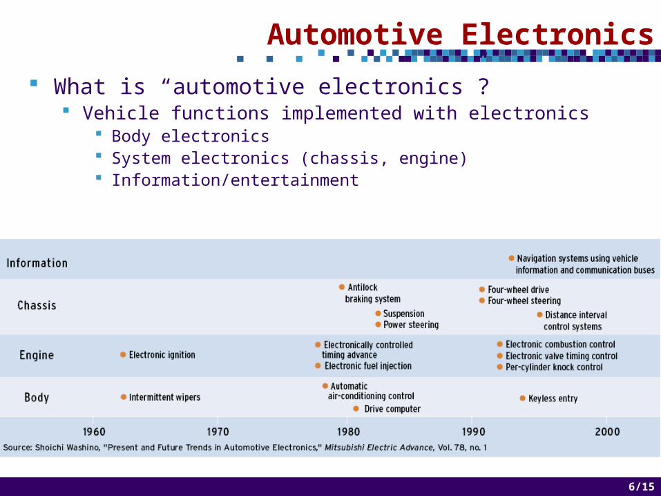
Automotive Electronics
What is “automotive electronics”? Vehicle functions implemented with electronics
Body electronics System electronics (chassis, engine) Information/entertainment
7 of 147/15
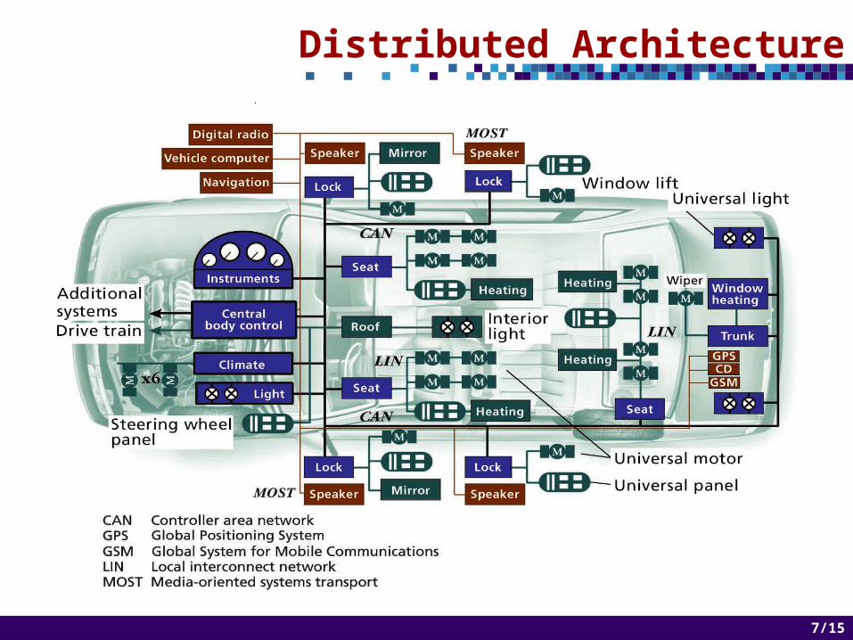
Distributed Architecture

8 of 148/15
Wiring: Point-to-Point vs. Network
Weight 5 Kg
1948 1994
30 Kg
Length of insulated wire 50 m 1500 m
Number of connectors 35 300
Number of terminals 75 2000
Number of individual wires
55 1500
1994: Wiring same price as the engine! Solution
Replace point-to-point wiring with a multiplexing network
Protocols LIN: Local Interconnect Network (body electronics) CAN: Controller Area Network (system electronics) TTP: Time Triggered Protocol (system electronics) MOST: Media Oriented Systems Transport (infotainment)
9 of 149/15
...
...
...
I/O Interface
Comm. controller
CPU
RAM
ROM
ASIC
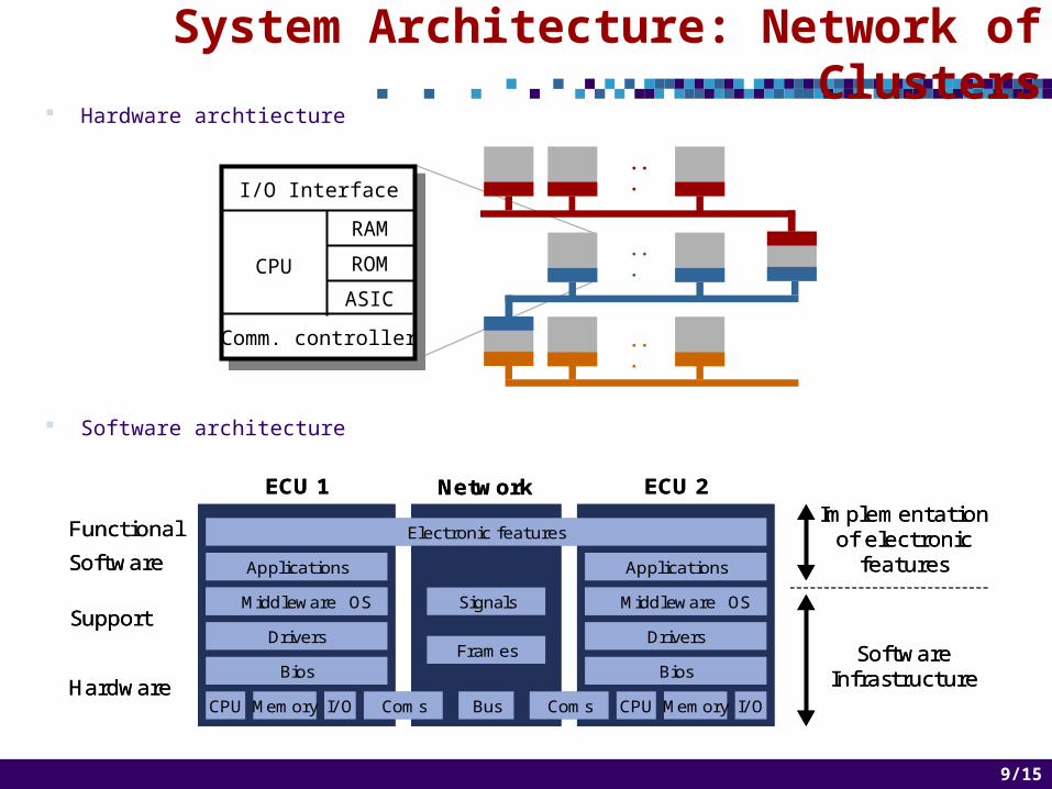
System Architecture: Network of Clusters
Hardware archtiecture
Software architecture
Applications
Middleware OS
Drivers
CPU Memory I/ O Coms CPU Memory I/ OComs
Signals
Frames
Bus
Electronic features
ECU 1 Network ECU 2
Functional
Software
Hardware
Support
Bios
Applications
Drivers
Bios
Middleware OS
Implementationof electronic
features
SoftwareInfrastructure
Applications
Middleware OSMiddleware OS
Drivers
CPU Memory I/ O Coms CPU Memory I/ OComs
Signals
Frames
Bus
Electronic features
ECU 1 Network ECU 2
Functional
Software
Hardware
Support
Bios
Applications
Drivers
Bios
Middleware OSMiddleware OS
Implementationof electronic
features
SoftwareInfrastructure

10 of 1410/15
Typical Application: Controller
Driver
Instruments DiscreteSwitches
Actuators ContinuousSensors
Reference
Modes
Controller
Physical environment(vehicle)

11 of 1411/15
LCD Display
Km
C
Engine pulses
Wheel pulses
Water Temp.(V)
Fuel level(V)
microprocessor(two options)
A/D 2
A/D 3
LogoDriver
LogoDriver
LCDDriver
LogoDriver
Car speedKm/h
Engine speedRPM
Fuel Level
A/D 1
Body Electronics: Dashboard Controller
Constraints Wheel signal: 0-1,000
Hz Engine speed: 0-400
Hz
Architectures Motorola 68HC05
Needs external drivers
Motorola 68HC11 On-chip drivers
Microcontrollers
12 of 1412/15
Body Electronics
Constrains Very low cost 100-200 ms (reaction of the human operator)
Characteristics Node
Single-chip 8 bit micro-controller > 100 bytes of RAM > 1K of ROM I/O points to connect sensors and actuators Simple network interface
Network Low bandwidth, ten to twenty nodes (LIN)
13 of 1413/15
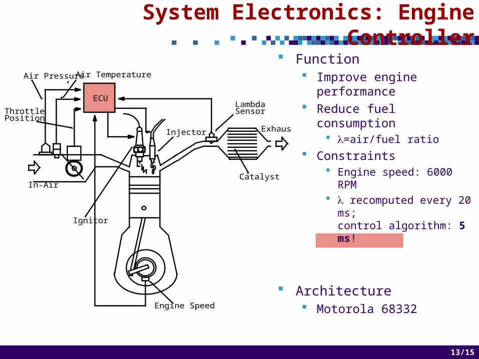
System Electronics: Engine Controller
ECULambdaSensor
Catalyst
Exhaust
Ignitor
In-Air
ThrottlePosition
Air Pressure
Injector
Engine Speed
Air Temperature
Function Improve engine
performance Reduce fuel consumption
=air/fuel ratio Constraints
Engine speed: 6000 RPM recomputed every 20
ms;control algorithm: 5 ms!
Architecture Motorola 68332
14 of 1414/15
System Electronics
Constraints Low cost Typical control loop periods range from 1 ms to 20 ms
Characteristics Node
Architecture influenced by its real-time constraints: 8, 16, 32 bit microprocessors, up to 16K of RAM and 256K of
ROM Memory grows more than 25% / year Complex network interface I/O points to connect sensors and actuators
Network High bandwidth, CAN or TTP

15 of 1415/15
Embedded Systems Design
TODO: Insert here slides about
Embedded systems design flow Functional analysis: EAST-ADL Platform selection, Mapping, Scheduling Case study in Generic modeling environment (GME)

16 of 1416/15
Event-Driven vs. Time-Driven Systems
Event-driven systems Activation of processes is done at the occurrence of
significant events Scheduling event-triggered activities
Fixed-priority preemptive scheduling Response time analysis:
calculate worst-case response times for each process Schedulability test: response times smaller than the deadlines
Time-driven systems Activation of processes is done at predefined points in time Scheduling time-triggered activities
Static cyclic non-preemptive scheduling Building a schedule table:
static cyclic scheduling (e.g., list scheduling)

17 of 1417/15
I/O Interface
TTP Controller
CPU
RAM
ROM
ASIC
Node
Time-Triggered Embedded Systems
Hard real-time distributed systems. Nodes interconnected by a broadcast communication channel. Nodes consisting of: TTP controller, CPU, RAM, ROM, I/O
interface. Communication between nodes is based on
the time-triggered protocol.

18 of 1418/15
Time Triggered Protocol
H. Kopetz, Technical University of Vienna.
Intended for distributed real-time control applications that require high degree of dependability and predictability.
Recommended by the X-by-Wire Consortiumfor use in safety critical applications invehicles.
Integrates all the services required in the design of fault-tolerant distributed real-time
systems.
S0 S1 S2 S3 S0 S1 S2 S3
TDMA RoundCycle of two rounds
Slot
Bus access scheme: time-division multiple-access (TDMA).
Schedule table located in each TTP controller: message descriptor list (MEDL).
I/O Interface
TTP Controller
CPU
RAM
ROM
ASIC
Node

19 of 1419/15
Software Architecture
P1 P2
RT-Kernel
MBI
CPU
TTP Controller
P3
RT-Kernel
MBI
CPU
TTP Controller
S2 S1 S2
tm 2
m1m1
m2m2
m2 m2
N1 N2
Round 2
P1
m1 m2
P2 P3
a) Application
b) Message Passing Example

20 of 1420/15
Application Modeling: Functional Blocks
Assumptions (the functional blocks are pre-processed) One single period Loops are removed Links represent synchronous communication Worst-case execution time (WCET) is given for each elementary
function
f1
f3
f2 f4
f5
21 of 1421/15
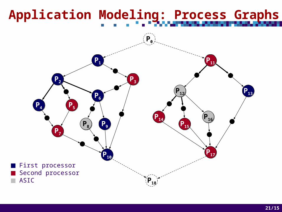
P4P4 P5P5
P7P7
P13P13
P15P15
First processor Second processor ASIC
P0
P18
P1P1
P2P2 P3P3
P6P6
P8P8 P9P9
P10P10
P11P11
P12P12
P14P14 P16P16
P17P17
Application Modeling: Process Graphs

22 of 1422/15
Problem Formulation
Input System architecture Application modeled as functional blocks A synthesis algorithm (mapping and scheduling)
S1 S0
P1 P4
P2
m1 m2m3 m4
P3
N1
N2
Bus
P1
P4P2
P3
N1 N2MappingWhere to
place a process?
SchedulingHow to
execute processes?

23 of 1423/15
Problem Formulation, cont.
Output A process graph such that the implementation
(obtained using the given synthesis algorithm) is schedulable
The synthesis algorithm produces Mapping Schedule tables
24 of 1424/15
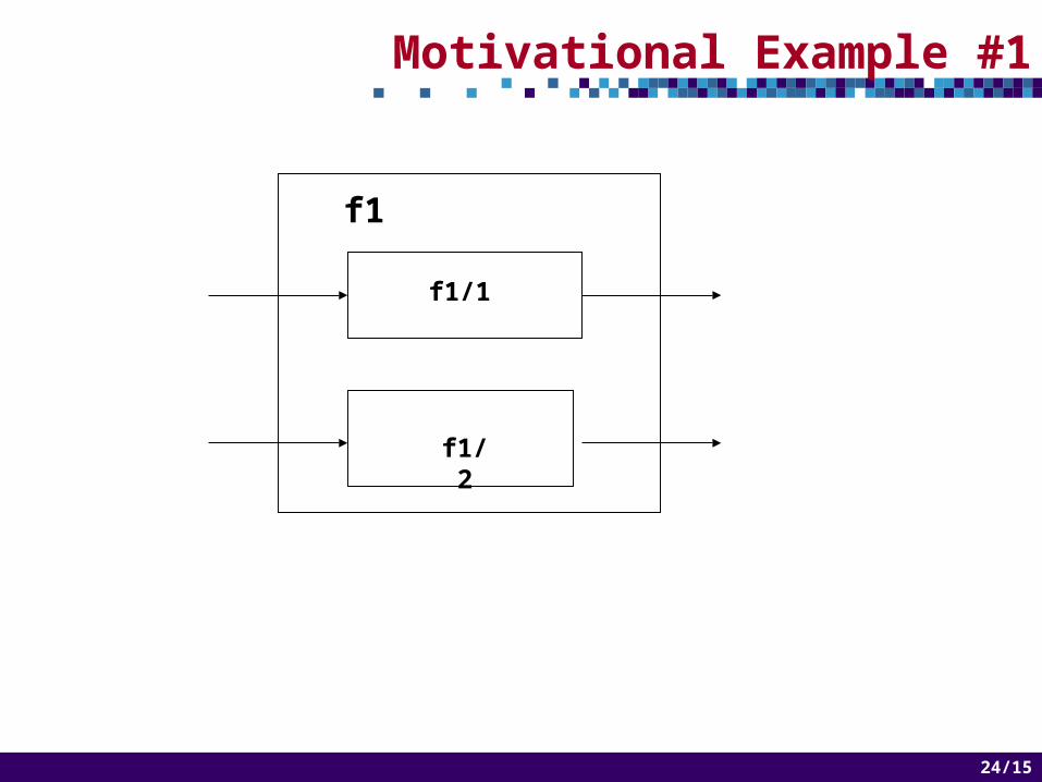
Motivational Example #1
f1
f1/2
f1/1

25 of 1425/15
Motivational Example #1, cont.
N2a)
P1N1
N2b)
P1/1N1
P1/2

26 of 1426/15
Motivational Example #2
f1
f2
f4
f3 f5
f6f4/1 f4/2

27 of 1427/15
Motivational Example #2
Deadlinefor P6: D6
P4
P5
P3N2
N3
P6 Meta)P2
P1P2P3P4
N1 N2
X XX5070
40
XX
P5 X 40
Deadlinefor P5: D5
P3
P6P5
P4
P2P1P1N1
P4/2
P5
P3N2
N3
P6 Metb)P2
P1N1
P4/1
N2 N3N1
TTP
N3
P6
70X
XX
XX 40 XMissed
Met
28 of 1428/15
Optimization Strategy

29 of 1429/15
Experimental Results
30 of 1430/15
Experimental Results, Cont.
Case study in GME Vehicle cruise controller