1 .o introduction figure 1 provides one definition of .o introduction the purpce.e of this document...
TRANSCRIPT

1 .O INTRODUCTION
The purpce.e of this document is tc provide a basic introduction to the topic of developnental' avionics flight teot. The target reader is the novice, juet being intrcduced to the subject, auch as a #tudont at one of the temt pilot mchools, or a pareon ju.t beginning in the field. The paradigm uaed in constructing tha bock was the curriculum at the test pilot achools, particularly, the United Statee Naval Test Pilot School, which has an avionics flight test specialization. There are many aimilarities between the flight test techniques that follow and those taught at the achoole.
Figure 1 provides one definition of the categories of aystems included in the fi&l of avionicl. Unfortunatoly, mpace constraints do net allcw dimcummion of a11 of these catsgorie9 in one AGARD publication and thua three are aingled outr radar, electro-optical and navigation. Aa at the test pilot Schools, the teaching technique chosen here is demonstration. The intent is that if the atudent can be made to understand the development of the sample test techniquea shcwn in this bock, ha or she cari thon extrapclate tc different systems and platforms. A thorough understanding of the test development proceee ha8 an added benefit. 1t la plausible that the tester may clcme day
igure 1: Categories of Avionics
2
be presented with a completely new class of system, for which thera are no previous techniques developed. If the logic of tho developnent of the existing techniques desctibed here is understood, then the tester will be able to invent the new ones as required.
The three classes of systems were chosen for several reasons. First, these are the same systems emphasized at the schools, providing a hietory of ~"ccessf"l test pilot training. Next, it in possible to develop a totally unclassified discuosionwithin thethree chose" areas that is releasable in open 1iterature. Electronic Warfare WaS net considered due to security iaeuee. Computer* and software were Ilot discuased bacauee even a basic primer on this subject would require a chapter latger than this document. Aircraft monitoring and control systems teating cannot be fully diecussed without considering their effects in terms of airframe handling qua1itiea and performance. Theee topics were beyond the scope of this document. In the final ana1ysis, length precluded a discussion of even some of the remaining nine subjecte and the three emphaeized at the schools were selected for treatment. A fourth, Stores Management Set Testing, was added at the suggestion that the addition of a single electro- mechanical-alectronic system would add depth to the document.
since this book Will only provide an introduction to the avionics test subject, it ’ envisioned that eventually, morel~dvanced volumes Will be written for each of the avionice categories. AGARD documents are included as referencee or are in work which provide partial documentation of radar, navigation and Electronic Warfare (EW) testing as well as an exhaustive series on airborne instrumentation. It is highly recommended that AGARD, or alternative organizations, champion the crafting of documents neceesary to treat the balance of radar, navigation and electronic warfate testing, as well as the other areae not started. These documents would then serve as teferences for the active practitioner of avionics flight test.
This book emphasizes the most rudimentary form of the testa under discuseion. This was done primarily to
highlight the basic concepts on which the teets were designed. Typically, this implies that 1itt1e or no instrumentation, test ranges or outside test assets are uaed in the tests which are developed. In many practical app1icatione. more *ccuracy, documentation and numerical rigor are required. The reader muet then refet to the more advanced flight test documents or in their absence, to experienced teeters. It is noteworthy that in most cases, the baaic concepts of the test do not change when more test aseets are used and thus the utility of uaing the most rudimentary form of the tests for thia introductory book.'
In addition to the teaching benefite, the very simple, rudimentary methods often bave practical utility and should be documented. Often, these techniques are sufficient for the task at hand, when less accuracy and documentation are adequate. Money and time cari thus be saved. Next, complete inetrumentation a100 implies "ery complex, time consuming and expensive data reduction. There 1s often ?ZeZL1 pressure to conetrict the time limite that test assets are availeble for a particular test. The rudimentary data collection cari be taken concurrent with the more rigorous and the les* accurate information used to adjust the next test event while data reduction occurs concurrently. The less accurate ""mbete ca11 also be used to highlight problem areas and areas where requirements are easily met. This allows data reduction assets to be used where they are moet needed.
Another important topic which was net documented in this book is the statistical implications of the tests, including the methods of *ample eize prediction, data convergence, etc. A few conunents are made to highlight tests which bave particulerly troublesorne statistical issues; however, the reader is cautionad to review any number of texts on statistics and experimental design pria to performing any rigorous teeting. References 43 and 72 provide an introduction to the subject.
In order to facilitate the unclasaified demonstration of the development and application of the *ample test procedures, fictitious systems were chosen and placed within equally

3
section is included in the first part of each section. Knowing the theoretical limits allows a more efficient test to be develoDed. This lxocess is demonstrated later in the case study of section 7.
fictitious platforms. The specific procedures and data cards, which may include altitudes, airspeeds, target separations etc., are applicable to the sample syetem only and appropriate parameters muet be chosen forthe actual system/airframe combination under test.
In aPPlYing this document, basic knowledge in certain areas is assumed. The test planner ehould bave a baaic knowledge of avionics, although an electronics background is definitely not required. A familiarity with the operetion of tactica1 aircraft la a1so important. Atheory section is provided at the beginning of each of the three major sections with specific, amplifying information included in the general section of each test. The purpose of this information is to ptovide the reader with the knowledge necessary to comprehend the specific example system and test procedures that follow rather than a complete treatise of the entire subject. The intent is to preclude extensive outside reading to underetand the test developnent process. When the time cornes to apply the test development knowledge presented here to a real evaluation, an extensive understanding of the workinge of the system under test is absolutely essential and the cursory treatment here Will undoubtedly be insufficient, aven if the systems are similar to the sample systems.
The 1ayout Of the individual test sections was carefully chosen with several goals in mind. Each test is fairly self-contained, exclusive of the information in the general theory sections. This allows the user of the manu1 to extract epecific sections, reference them easily and quickly and review individual tests on the occasions where they are applicable to the system under test. In addition, the titlee and contents of each section bave parallels to the accepted test plan and technical report structure. Finally, the layout ie similar to that used in the long accepted flying qualities and performance flight test manuals (see reference 47 for an example).
The test development process is manifesteà in the structure of the sections to f0110w. As mentioned above, the procedute is begun by exploring and fully understanding the design of the aystem under test. This understanding provides the insight neceseary to etrese the system and test it to its limita and also allows the calculation of the theoretical limita of the system. General theory applicable to each
The choice of which parameters to test ie best (and only) determined by a thorough knowledge of the workings of the aystem and its intended functionality. The process cari be divided into two steps. First, the evaluator muet define the required functionality of the system. The functional description should be defined in operational, vice engineering, terminology. This step requires a knowledge of the intended mission of the system. Secondly, the evaluator must choose the kernel of parameters which measure the performance of the required functionality defined in the firet etep. This taek requires a thorough system knowledge. These parameters are then used as a guide for the developnent of the individual test procedures. The test procedures are designed to measure at least one of the critical performance parameters. The individual test procedures listed in the next three sections are titled according to the parameter under test.
The firat subsection of each test procedure describes the purpose of the teet, which more precisely defines the parameters under test. In the general section, the basic theory outlined in the beginning of the section is expounded upon as neceesary to fully implement and understand the teet procedure. The instrumentation requirementa neceseary to measure the parametets described in the purpose statement are then listed followed by the data required to document the parameter. Next, the procedure for performing the test is described in datai1 followed by a discussion of the post-test analysis of the measured data requiredto answerthe purpose statement and the recommended format for presenting the test results. The last part of each test procedure is sample data carde used to perfotm the test procedure and for recording the data during actual testing.
In eummary, the test design process cari be described as outlined below. 1t may be necessary to change the order in which the tasks are performed as well as the relative importance of the taeks from test to test, but the list below will provide a guide for the general case.

4
(1)
(2)
(3)
(4)
(5)
(6)
2.0 AIR-TO-AIR AND AIR-TO-
Research and understand the deeig" specifications and operational uee of the system undet test. Uee thia knowledge to define the parameters critical to aeeeeeing the performance of the system and a1so as * means for calculating the theoreticel boundariea of the eyetem'e performance. Precieely define the purpose of the test procedure to include the parametere to be measured during the test. Define the data "eceseary to calculate the parameter under test and aeseee the i"strume"tati0" requiremente "eceseary to measure the data. Outline the detailed procedure "ecessary to perform the data collectio" effort. Definethe analysia "eceeearyto take the meaeured data and calculate the parameter u"d& t%ezd then decide upon the proper presentation format to document the parameter. Ae a lest. effort, generate data cards that provide a" outline of a11 information necessary to perform the data collectio" effort and record the reeulta.'
GROUND RADAR SYSTEMS TESTING
2.1 Introduction to Radar Theory
2.1 .l General
Radar (Radio Detection And Ranging) wae first ueed operationally in 1937. This rudimentary eyetem included a simple puleed echeme to determine target bearing and range. [Ref. 9:p.ll. The first succeseful airborne radar was the Al Mark IV carried on the Bristol Beaufighter 19 in 1940 which used eimple puleed techniques to determine airborne target range [Ref. 56:p.Z). Prom these humble beginnings, radar has developed to the point that it bas become the centerpiece in virtually every modem airborne weapo" system. In the very simple& terme, a radar sende into space
a Radio Frequency (RF) puise of know" characteristics, waite for the waves reflected off the target to return and analyzes the characterietics of the returned wave to derive information about the reflacting targat [Ref. 39:p. 2.11.
2.1.2 Pulsed Radars
The aimplest of radars are the puleed radare. The operating principles Of pulsed radars are based on the fact that RF energy propagates through space et a constant velocity. Thie velocity, strictly speaking, ia applicable only in a perfect vacuuin and le altered slightly by the atmoephere. Propagation ve1ocity 1s a function of transmiseion frequency, and atmoapheric molecular composition, temperature and p+eesure. The speed of propagation increaaes slightly et higher altitudes [Ref. 11:~. 81). Thie effect is small; hcwever, et the ranges and frequencies discuseed in this section. For airborne test purposes, a "radar mile" of 12.36 microseconds ca" be defined, which is the time required for RF energy to travel Out One "autiCe1 mile (nm) and then return [Ref. 27:~. l- 4.21.
The basic components of a pulaed radar include a tranemitter, receiver, two antennes and a display [Ref. 60:~. 41. TWO antennas are included becauee the syetem requirea a transmit antenna and teceive antenna. 1" practice, a Si"gle antenne is time shared for both purpoees. A duplexer is used to switch betwee" the transmit and receive aides of the radar. The transmit side ie connected only when actually firing a puise and the receive aide is connected to lieten for returned pulsee. [Ref. 5.6:~. 41. This scheme prevents the transmit puise from being directed to the receive sida of the radar.
Transmitter antannas are usually designed to concentrate the transmitted pulee in as narrow a beam ae possible. Similarly, receiver antennae are deeigned to receive signale within the same "arrow beam. This phenomeno" of eesentially equal performance of the antenne in both transmit and receive modes ia known as reciprocity and cari be useful in designing tests [Ref. 36:~. 2.132).

The antenna beam width ie usually defined at the 3 decibel (db) power drop off points each eide of the radar antanna boresight and ia usually measured both horizontally and vertica11y [REf. 36:~. 2.135a, I7ef. 27:~. 3-1.1, Ref. 21:~. 661. Beamwidth is critical mince it Le through thie characterietic that the direction to a target is determined. As the antenna is acanning, or moved in a search pattern, the antenna pointing angle with reepect to the aircraft is measured. The rate of antenna movement is insignificant when compared to the RF propagation speed. Thus the relative angle at which the radar antenna ie pointing when the signa1 is sent out, reflected and returned, is the angle to the target. (Ref. 39:pp. 2.8-2.91. The angle to the target is determined both horizontally and vertically. Target angle detetmination etrors cari be incurred due to the beam width of the antenna and to inaccuraciee in the measurement of the antenna pointing angle. It must be noted that some modem radars tan provide azimuth resolution bettee than the antenna beamwidth. With the exception of doppler beam sharpening, to be discussed in the air-to-ground radar section, thaee technologies will not be covered in this document; however, the test techniques are similar.
Antenna beau width also determines the minimum angular resolution of the radar. When two targets are at the eame range from the radar, they must be separated by at leaat the antenna beam width to be diatinguishable as two targete. since the returned radar puises from the two reflecting targets will arrive at the antenna face simultaneously and will thus be unreeolvable without additional information (which will be discussed later). [Ref. 39:pp. 2.9-2.101. Air-to- air radar antennas generally strive for small horizontal and vertical beam widths because this improvee both tha vertical and horizontal angle determination of airborne targets. Air- to-ground radar antennas use ema11 horizontal beam widths and wide vertical beam widths, providing accurate horizontal angle deteemination with ressonable vertical distribution of energy over a wide range for coneistent radar mapping gualities. [Ref. 56:~. 8). A,, even distribution of energy over the ground allows the radar to present a more mep-like display for wide rangea with fewer gaps where the radar ie not illuminating [Ref. 56:p.146].
Up to this point, a very important shortcoming of a11 real antennas has
5
been ignored. The effect is called sidelobing. When the desired main beam pattern is transmitted, additional patterns of similar shape but smaller "n;ude$e ;n;n;M_tte? at intervals
rn a three- dimenaional pattern. Figure 2 shows the effect in two dimensions. Al1 real antennas bave this problem to xnne degree; although, the number of sidalobes and theit intensity relative to the main beam vary with the guality of the antenna. The sidelobe pattern also typically changes when the antenna is installed on the airframe. Modem antennas greatly suppress the sidelobe problem with a decrease of from 20 to 100 db in the sidelobes from the main beam peak magnitude. A return from a aidelobe canot be distinguished from a mainbeam return without special processing, and the azimuth of the eidelobe return appears to be that of the main beam return. (Ref. 56:~. 1381.
A number of antenna scan patterns bave been used for air-+x-air and ait-to- ground radars. Most modem radars use a gyroscopically orinertially stabilized, gimbal mounted antenna that allows the scan pattern to remain lave1 with the horizon as the airplane ie maneuvered [Ref. 56:p.24]. There is usually scnne maximum physical limit for diaplacement relative to the hoet aircraft, both horizontally and vertically. Since the antennas are normally mountad in the ail-plana nose, structura1 interference and RF interference with the airframe necessitates these limita. A limit of 60' left and right hotizontally (azimuth) and 45' up and down vertically (elevation) are typical. A raster type antenna scan pattern is usuelly used. The raster scan moves horizontally left and right between tha selected limits. Usually two or three angular widths are available for selection within tha physical limita described above. Oftan the operator 1s also able to Select the location of the tenter of the scan pattern, again within the physical limita described above. An operator would normally Select a scan pattern 1ess than the maximum limita and directed towards the target when the target bearing cari be estimated. Thia provides more frequent scanning of the target area to reduce detection time. FO?Z air-to-air applications, the horizontal path is usually stepped up and then down by an incremental angular amount. Each horizontal scan ie known as o bar and may be selected in number [Ref. 56:p.5], usually from one to four. Each bar typically overlaps slightly.

6
AS the "umber of bars and the sca" azrmuth width are increased, the eearch volume increases and consequently the time betwee" target illuminations increases. 1ncreaeing antenna SCB" rate ca" be used to counter this problem somewhat; however, if the sca" rate ie increased, the amount of time the target is within the antenna beam width, and thue the number of puises illuminating the target per BCB", is decreaaed. A tradeoff i6 "ecessary to optimize the number of hite per sca" and to minimize the time between scan~ over the target. Uaually the search volume ie limited to that which ca" be eupported by the radar and Will be tactically useful. A multiple bar sca" patter" is "ecessery to caver the search volume because a "arrow vertical beam width is needed to allow altitude of the airborne targets to be datermined. Knowing the vertical angle to tha target (calculated in the same mariner as the horizontal angle to the target) and tha target range, a simple geometric calculation provides the target altitude relative to the host aircraft. This ca" be added to the host aircraft altitude to determine the target altitude.
Air-to-ground radars "ormally operate with a single bar sca" patter", and therefore tha sca" rate and sca" angular width determine the refresh rate of the dieplay. The number of hita per sca" is maximized to maintain a consistent, map-like display and SO the tradsoff is one of providing a quick sco" rate to ehorten the refresh period and a long one to keep the "umber of puises over a given azimuth high enough to provide a consistent, map-like dieplay.
The ideal, pulsed radar sende out the RF energy in discrets packages (pulaea) of
specified duration. The pu1ea duratio" ideally ha8 very rapid riaa and fa11 Urnes. It is asaumed here that the rise and fa11 times are essentially instantaneous since modem radars corne very close to achieving this goal. The pulae width defines boththe theoretical minimum range and the theoretical minimum range resolution. The theoretical minimum range is defined in the following equation [Ref. 39:p. 2.781:

Any target closer than thia range will not be observed mince the duplexer will still be switched to the transmit side of the radar. The theoretical range resolution limit (Q, or minimum range resolution) is equal to the eame value. [Ref. 39:p. 2.8a]. Since the return from the ferther of two targets, that *re closer together than the range resolution limit, will be received at the receiver coincidentwith that of the nearer target and Will thus be unresolvable without additional information (discussed later). From theae consideratione a short pulae width is desirable; however, a long puise width is needed because energy is transmitted only during the duration of the puise and the averege power illuminating the target increases as the puise width is increased. This increases the probability of detection, a11 elae being equal. [Rrnf. 56:pp. 159-160).
The number of 'cimes that the pulsed radar transmit6 its puise per second ie known as the Puise Repetition Frequency (PRF). PRF determines the maximum theoretical "nambiguo"s range. The radar waits between transmissions for return pu1see. If the PRF is too high, and thus the time between pulsee is too short, the return from a previoue puise will return while the radar is waiting for the return from a more recent puise. The time interval between pulses is called the Pulee Repetition Interval (PRI). The radar would be unable to determina which transmitted puise the returns were aseociated with, and some returns would be aseociated with the incorrect time slot. [Ref. 56:pp.157-1581. Conversely, the PRF must be kept as high as possible to increaae the average power out of the radar and thus the probability of detection. There are methode for tesolving ambiguitiee hetweeninterpulse periods. The simple& is merely to vary the tranemitted RF frequency from puise to pu1ae, corre1ating e return puise with its asaociatedtransmitted puise by matching frequencies. For a
[Re;;d;;:p.,2.8]. simple pulsed wrthout
7
specia1 techniques applied, the theoreticalunambiguous maximum range is defined as [Ref. 39:p. 2.8b]:
Frequency cari affect the maximum range of the radar since some frequenciee are impacted by molecules and particles within the atmosphere more than others. The impact is * function of the wavelength of the radar RF frequency relative to the diameter of the various particles and molecules in the atmosphere. The effect cari be dramatic. Wavelength ie related to frequency by the following expression (Ref. 56:~. 125, Ref. 27:pp. 5-1.1-S-1.3]:
Some frequencies propagate through the atmosphere with less absorption than others. At the frequencies most used for air-to-air and air-to-ground radars, oxygen and water molecules are the grestest absorbera of RF enetgy [Ref. 56:~. 125, Ref. 27:~~. 5-1.1-5-1.3). Lower freq"encies cari actually propagate beyond the horizon by bouncing downward in the upper atmosphere, bouncing up from the ground and/or by conforming somewhat to the curvature of the earth [Ref. 36:~. 2.801. Air-M-air and air- to-ground radars are generally well above this frequency since the lower frequencies require large antennas (most antennas are optimized at multiples of 1/2 the RF wavelength). Virtually a11 the radars that fa11 in the categories discussed here radiate at between 6 Gigatiertz (GHZ) and 18 GHZ. A+ tl-lese frequencies moisture content Of the atmosphere has an effect because of the wavelength relative to the water molec"le's size. Also, these frequencies propagate essentially on a straight line path, that is, along the line of sight. [Ref. 36:~. 2.801. Above the 20 GHZ level, the atmosphere absorba virtually a11 the RF energy at short ranges [Ref. 36:~. 1251.
The tools have now been preaented to analyze one of the most crucial features to be evaluated on a new radar. This parameter is the maxFmum detection range of the radar (net the same as the maximum unambiguous range). Thia

characterietic receivee much attention during a test program because it La often the performance featute by which radars are compared and measured. Reference 36 providee a good derivation of the radar range equation which ia presented here without proof [Ref. 39:pp. 2.12-2.151:
P=Tranemi.tted power of the radar.
G=Directive gain Of the antenna, a meaeure of the ability of the antenna to direct the RF along a straight line rather than transmit it evenly around the antenna in a apherical pattern (isotropically).
o=The radar cross section of the target. "The radar cross section Of a target is that area which, when multiplied by the radar signal power density incident upon the target, if tadiated isotropically bythetarget, would result in a return back at the radar equal to that of the actual target" [Ref. 39:p. 2.161. SirnPlY. the radar cross section ie a measure of the ability of the target to reflect radar energy. The radar CJXXB section varies with the specific irequency, and thus wavelength, and changes, sometimes dramaticallv. as the ansle of incidence ;pon the target -changes [Ref. 39:p. 2.17, Ref. 28, Ref. 8, Ref. 44:~~. 89-1271.'
A-The radar antenna capture area.
L-A 108s factor which accounts for non-specific losses within the radar receiver.
(k)(T)(B,)(F.)=All are related to the interference withinthe syatem caueed by thermal noiee. Thermal noise is a function of the absolute temperature of the system and the band width of the system. Most modem radar6 bave coma close to optimizing this set of parameters; and, as such, there is little room for Fmprovement for the designer.
(S/N),=The Signal to Noise ratio ie a measute of the signa1 atrength divided by the noise received. The minimum signal to noise is that S/N that cari just barely be identified ae an actual target. The (S/N), depende on many factors, mont of which cari only be defined poorly. operator experience and the accepted false alarm rate are examplee of theae variablea.[Ref. 14:p. 2.151. Hodern radars cari have an (S/N), well below unity using advanced processing techniques to pull the target'e returned energy out of the noise level. Some will be discuseed later.
Note that the entire expreesion is raised to the 1/4 power. Improving any one factor by 16 will only double the radar range. [Ref. 39:p. 2.15). 0 ie a function of the target and not under the control Of the radar designer. (k)(T)(B,)(F.) are only slightly under the control of the deeigner since some thermal noise must exiat in any real system and most modem systeme handle this problem fairly well. L is very close to unity in many modem systeme ad; therefore, cannot affect the otder of magnitude changes necessary to significantly increaee the radar range. A is limited by the frontal cross sectional area of the airplane noaecone which is where moet radar antennas are housed. (Ref. 56:~. 127). This leavee P,G and (S/N)& for the designer to manipulate and affect maximum range.
Peak power out is usually limited by the physical weight and size of transmitters that have to be carried in airplanes. Lowering peak power reduces airplane weight. [Ref. 56: p.124). A pulsing scheme hae to be worked out to louer paak power while optimizing average power over time [Ref. 56:~. 159-1601. Generally, some modulation scheme of either frequency or PRF is ueed to allow increasing the pulee width or PRF to effect greater average power while at the came time not sacrificing other radar paramatric performance. some of these techniques are described later. Increasing average powar cari cause other problems. As power output is increased, the probability of the signal being received by the enemy and exploited is

increased [Ref. 39:p. 2.12-2.131. Since the Signal path to the enemy receiver is only a one "ay path, the radar range equation dramatically show6 the importance of kmeping the power levela within limite. One techniaue makee uSe of the ambient noise level-to hide the transmitted RF.
Antenna Gain iS improving at a slow but steady rate. Mo& modem radars rely on slotted array plana antannas which are a pattern of Slot shaped antennas aligned in a flat plane. These planar arraye achieve a G of as much as 40 db in current production eystams. The minimum signal to noise ratio ca" be improved by increasing the sensitivity of the receiver while at the same time improving the capability to reject ambient noise. Rejecting noise keepa the falae a1aZlll rate down. Ma"y techniques involve modulating the transmitted signal in a unique fashion "ot duplicated in nature to allow the receivet to differentiate between the retur" signal and noise. The power deneity ca" be spread out to a lower level than the ambient noise and then pulled back out at the receiver. This is poseible becauae a pseudo-random code known only by the transmitting radar is used to modulate the RF. The code must be known to pull the signal out of the noise. The signal is almost impossible to detect without the code eince the peeudo-random modulation makes it look like noise. This technique ie finding application in * large number Of current and developing communication and radar ayetems. [Ref. 36:~~. 2.108-2.1111.
2.1.3. Doppler Radars
The operating principles of doppler radars are baaed upo" the fact that RF reflections from a target that ie closing in range radially along the direction of propagation are shifted up in f requency , and reflections from a target that is opening in range are ehifted down in frequency. Thie phenomenon is demonatrated in the audio spectrum by a train paaeing with the horn sounding. The hor" sounds higher in frequency SS it is approaching and the" 1CMer in frequancy as it io receding. (Ref. 56:~. 9, Ref. 27:~~. 2- 2.1-2-2.51. It must be emphasized that this measurement is limited to radial velocitiee only [Ref. 56:~. 9, Ref. 27:~~. 2-2.1-2-2.5). A target could be moving hypersonically, perpendicular to a non-moving doppler radar, and it will exhibit a zero doppler shift. Anothet point to note in that a dopplet ehift is
9
alao imparted by ownship motion. For example, ground clutter directly along the flight path of the airplane will tend to exhibit a doppler ehift equal to the groundspee; of the airplane [Ref. 13:p.2.36, . 27:~~. 2-2.1-2-2.51. Several techniques are available for eliminating doppler shift dueto ownship motion. The simpleat technique is merely to filter out a11 doppler Shifte around the ownship groundspeed motion induced doppler value along the radar boresight [Ref. 56:p.9]. This technique is often used in air-+x-air radars.
A number of techniques have been devieed for detecting targeta that are moving with respect to ground clutter. These syeteme are known collectively as Moving Target Indicators [Ref. 39:p.2.48) or in the case of airborne radars as Airborne Moving Target Indicators (AMTI) [Ref. 39:p.2.291. One class of AMTI radars uses only the doppler effect to detect moving targets. These radars UBB very long pulses to increase the average powet and consequently ca""& determine range to the target. In this situation, the only reaso" pulsing is used is to allow the same antanna to be employed to transmit and to recaive. Target bearing la found as in pulsed radars. The high average power and sensitivity to cloeure rate make these radars ideal for gaining relatively long range detection on high closure rate targets. The high average power output improves small (I target detection (the increase in P compensatee for a small (I in the radar range equation). The rejaction of ground clutter based upon tha ownship motion doppler shift filtering described above also increases the probability of small target detectio" in the clutter. Al1 these effecte make the doppler mode of operation ideal for the detection of small, 1OW flying cruiee miseiles closing on the radar.
Several doppler radar parameters affect the performance of the system. O"e parameter is the accutacy with which the doppler shift (frequency change between the transmit and receive signal) ca" be measured. This XXuraCy directly relates to the ability of the radar to discern between two targets close together in bearing and also close together in closure speeds. As the difference in doppler shift approaches a ValUe eqUa1 to the doppler shift aCC”raCy, the targets become unresolvable in closure Speed. The uncertainty in doppler frequency ehift is directly convertible to a cloeure rate uncertainty. [Ref. 39:p.3.18].

2.1.4. Puise Doppler Radars Puise doppler radars combine the ranging capabillties of the pure pulsed radar with the cloeure velocity determination capability of the doppler radar. With this technique, doppler shift measurements are applied withi" the pulae width of the transmit and reply signal providing the best of both radars, although not without added complicatio"a. Al1 of the performance limitations of both puleed radars and doppler radars aPPlY; however, the pulslng of the doppler RF adde eeveral new limitations. The first is caused by the effects of fraquency folding or aliaaing. [Ref. 39:p. 2.341.
The pulsed radar is eesentially a data sampling system and. as in any eampling system, "the sampling process createe "ew frequencies, other than the deaired transmit frequency, which raplicatea the desired spectrum in the frequency domain, at intervals equal to the sampling rate" [Ref. 39:p. 2.34). The sampling rate ie equal to the PRF for radar applications [Ref. 39:p. 2.341. The retur" signal replicates itaelf at a 1ower power 1eve1, at multiples of the radar PRF [Ref. 39:p. 2.34131. deacribed, this affect occurs for "1 simple ainuaoidal signal and becomee eve" more complicated if the signal is further modulated as are most radar signala. Since the doppler portion of the puise doppler radar meaaures the frequency change of the transmitted RF, this problem is serious and resulte in ambiguous doppler shifte, and thus ambiguoue radial velocities, at each frequency fold. [Ref. 39:p. 2.351. The solution to the problem is to Select a PRF high enough such that the firet frequency fold occurs at a doppler shift, and thus a cloeure epeed, higher than of interest to the operator. 1" a pulee doppler system this ia contrary to the requirement of having a low PRF to prevent range ambiguitiee. A tradeoff occure in these radars batween low/high PRF and thus range ambiguities/closure rate ambiguities. The beat solution depende "po" the intended use of the radar. [Ref. 39:p. 2.421.
Another problem resulte fromthe effecta of ground clutter returne on various portions of the radar transmiesion pattern. Since a11 real radar antennas bave antenna patterns with sidelobee outside the main radar beam, ground clutter returne are of threa different types. The highest amplitude retur" is caused by the main beam itself and ia
due to the doppler shift from ownehip motion along the radar line of sight. Along with this retur" ia a return which is much wider in its ftequency apectrum and louer in power caueed by clutter in the radar sidelobes. Finally, a "arrow frequency spike occurs at the transmit frequency due to the retur" from the ground immediately below the aircraft. Thie ie called the altitude return. The entire apectrum is illustrated in figure 3 (Ref. 39:pp. 2.35b-2.363.
Without further processing, the target return would bave to be strong enough to break out of the clutter and noise combi"atio". It ie "ery unlikely that a emall target would be aee" within any of the clutter pedestals deecribed. A common method of handling this problem ie simply to fllter out a11 of the main beam, altitude retur" and sidelobe clutter pedestals, requiring the target to only break out of the noise (Ref. 39:p. 2.371. IJ"fortu"ately, this eliminates a wide epectrum of closure rates where the target would not be seen, but leaves few false alarme. Other radars leave the aidelobe clutter pedestal. The effect ia fewer excluded closure rates but a lot of noise in the sidelobe clutter pedestal for the radar a"d/or the operator to sift through. The target return must be strong enough to be see" ineide the pedestal [Ref. 39:p. 2.371 and the falae alarm rate is usually increased. Fortunately, other methods bave been deviaed for dealing with clutter. One Will be discussed here as a" example. Delay Li"e Cancelera (OLCe) allowthe radar to save the return puise from one PR1 to another f;;tehe" to pass the two through a
The two are eseentially eubtractad from each other and the difference ia due to changes over time, that is, motion over the ground clutter.
When uaing the simple method of aubtracting out the clutter pedestals, there are resultant blind speede, around the speed of ownahip, along the radar line Of sight. This problem ie complicated when frequency folding occurs aince thie leavee one blind cloeure rata for each fold. When using DL&, there is a minimum epeed over the ground clutter that the target muat make for the DLC circuitry to be able to discern a minimum resolvable change from puise to puise. Thie meana there is also a minimum reeolvable cloeure rate. DLCs are alao susceptible to frequency folding just as in other pulee doppler systems and thua theee minimum doppler ahift closure rates may be repeated at

FIRST LOWER PRIMARY FIRST UPPER FOLDED BPECTRUM SPECTRUM FOLDED
SPECTRUM 4 p b
dit REGION
ALTITUDE MAINLOBE RETURN CLUTTER
8 SIDELOBE CLUTTER y
F, F. -Fdt Fo+PRF
FREQUENCY
F. =transmitted carrier frequency
PRF=pulse repetition frequency
Fdt=doppler shift due to target radial velocity Laurr 3’ air-borne P”I..% nnnn1ar Return crlPP+?Ylm .____ _. _.-_--_..- - ---- --cr--- _ ._ _ _ _ . . _C_____..,
intervals over the velocity epectrum. (Ref. 56:~~. 425-4261.
delay. The effect is to stack the return puise. The result is to provide better range resolution from the narrow procassed puise width with the benefits of high average power from tha wide transmit puise. Typical compression ratios are around lOO/l. [Ref. 56: pp. 217-2181:
2.1.5. Advanced Techniques
1.1.5.1. Puisa Compression
The first advanced technique to be discussed is puise compression. In puise compression, the transmit pulee ie generated with a spread of frequencies within a defined band. The puise is then passed through a filter, callad a Dispersive Delay Line (DDL). The effect of the DDL ie to arrange the RF within the pulee such that the 10weJC frequencies are transmitted at the beginning of the pulae width, linearly incraasing to the higher frequencies by the end of the pulse width. The return puise ie then passed through the same filter in the opposite direction, which slows the lower frequencies in the lead and by the end of the puise appliea no
2.1.5.2. Doppler Beam Sharpaning
The naxt technique to be discussed is Doppler Beam Sharpening (DM). DBS has found application mostly in air-to- ground radars. As the radar antenna is scanning, the antenna boresight moves from side to side. The grand target doppler qhift is a measure of the component of the host airplane's

velocity along thi8 boresight. Al1 fixed ground targets bave a doppler shift caueed by the geometric component of own aircraft motion along thie boresight. For theee reasone, ae the antenna S~ans, the ground return doppler shift will change by a predictable amount. DBS makes "se of this concept by measuring the doppler shift of the ground returne and comparing themto the doppler returns for adjacent returns in azimuth to determine very precise angle8 off of the eircraft ground track. The result ie a "Rry precise angular determination for target returns, much better than the antenna beam width. Unfortunately, the doppler shifts vary slightly from puise to puise around the theoretical value and the information muet be integrated over time to get the truc value. A lot of radar information must be etored to dieplay the entire search volume and the display often ,W&reS 10 to 15 Seconds to build. The data Le normally stored in small angular and range bina within the radar computer and the display usually appears like small building blocks of varying intensity. A lot of computer memory and processing time is required for this proceas.
SiDCB DES on1y affecta angu1ar reso1ution. Some technique is needed to improve range resolution consietentwith tha angular improvement. This is usually accomplished merely by decreasing the puise width of the transmit signal enough to provide a harmonious balance of angular and range resolution. The reduced pulee width also reduces average power and in turn reducee the maximum DES range to 40 or 50 nm. Another limitation of DBS is caused by the geometry of the technique. The doppler shift change close to the radar ground 'crack is very amall as the radar sweepe, increasing by the cosine of the angle off of the ground 'crack to a maximum aS the perpendicular position is reached. A minimum discernable change is required to be reeolvable, caueing a small notch, usually 7' to 15' wide, over the nose of the airplane, where the DBS picture is blanked. In some radars, this is filled, with limited succsss, with real beam radar video. Moet state of the art DBS radar8 cari provide a map like display with an order of magnitude improvement in tesolution within the constraints discussed above. (Ref. 56:pp. 2.66-3.29).
2.1.5.3. PM Ranging
As diacussed above, the more continuous the transmission pattern, the higher the average power out and the longer the maximum detection range. The drawback of extremely long puise widths is that ranging of the target becomes impossible. Frequency Modulation (FM) ranging provides ranging data even with very long or continuous pulse trains. In FM ranging, the puise train is ramped linearly up in frequency to a peak from Borne baseline frequency and then linearly ramped down to the original baseline. This pattern ia repeated at intervals roughly equivalent to conventionalpulse repetitionintervals. The return pulee is then compared to the transmitted puise to find the peak, providing a time reference from which to determine the time of propagation to the target and back. Instead of measuring the time fromtranemiasion to receipt of a discrete pulse, the time from transmit to receipt of the peak is meaeured, providing range. [Ref. 39:pp. 2.29-2.32). In practice, thie technique is much less accurata (by as much as an order of magnitude) than puise ranging and has poor resolution, but reasonable ranges cari be determined for the long range targets that the wide pulse width radars are designed to detect. The raduced range tesolution and accuracy are resu1t of the inherant inaccu:acies associatedwithdetermining the precise point of the frequency peak. [Ref. 56:~~. 239-2401.
2.1.6. Displays TWO types of display formats bave found application in most modem air-to-air and air-to-ground radars. The most widely used, and moet versatile, is tha Plan Position Indicator (PPI) format. In this format, the sweep emanates from a single point, usually the bottom tenter of the ecope, and describes a slice of a circle with radius equal to the eweep length. The origin of the sweep ia the ownship position and the target's position relativeto ownship is measured as the bearing of the sweep and range from ownship. [Ref. 56:~. 25, Ref. 27:~~. 5-5.3-5-5.6). since a pure bearing/range format from ownship is used, the display closely resembles the real world. That is, if a mapping mode is being used, the radar display will resemble the real world. The bearing and range measurements are made os direct line of sight measurements and as such do involve some slant range errors. These errors account for slight

distortions at short ranges. Another short range distortion is caused by the very ahape of tha display. Since the display comas to a notch "ear ownship, targets "car the notch of the " are very cluttarad, and as such, resolution geneta11y suffers very close into ownship. Both of theee short range dieplay problems ca" affect the minimum usable range of the radar and ca" cause it to be greater than the theoretical value described earlier.
Some applications reguire a quick and accurate repraeantation Of target bearing and range more than the map like picture deecribed above. 0ne application is in fightare, where accurate target angle and range information is required to aet up and execute intercepte. For these purpoees, the B ~CL" format dieplay has found application. B sca" dieplays are set up with range on the y axis and angle to tha target on the x axis [Ref. 56:~. 25, Ref. 27:~~. 5-5.3-5-5.61. Thia format is more a dieplay of information rather than a picture of the real world. Tha effect is to "spread the world out" at short ranges, distorting the picture. The B sca" has limited application in tha air-to-ground arena, although some applications exist. Air-to-ground B sca" applications are ueually limitad to emall area displays offset from ownship (patch map) [Ref. 56:~. 251. DBS often uses a B-ecan format to facilitate conversion from memory storage in the range and azimuth bine to dieplay. Velocity Search (VS) modes are displayed with angle to the target on tha x axie and closure rate on the y axis (Ref. 39:p. 3.261. Figure 4 includes samples of several display formats.
Display raeolution is important in a11 display formats. Often the display has less resolution than does the radar systam. As o raeult, a lot of good radar system deeign work euffers. Cathode Ray Tubes (CRTs) are used in most displays today. Theee displays bave a fairly well defined reeolution based upo" the number of raster lines per inch, or the number of reeolvable points per inch that are displayable. This number ie applicable to both dimensions on the display. Knowing the selected range scala, the thaoretical resolution limit ca" be determined.
For the digitally drive" CRT digital displays in use today, tha presence or
absence of a target is usually eaaily interpreted by the operator. For the old ana1oa disr>lavs still in uee. display g&lity; éystem set up ani operator proficiency ca" greatly affect nearly every radar parameter.
2.1.7. Analog Versus Digital Displays
Almost a11 "ew radar system displays are implemented in a digital format. This means that analog to digital conversion of the radar return takae place and some amant of radar processing is used bafore the information ia dieplayed to tha operator. The benefit ie a cleaner display gleaned from the chaos of the analog world with only the "ecessary information making it to the dieplay. Decreasingthe unusable information from the display tends to reduce operator workload. This is perhaps the major advantage of the digital format. Tha dimplays are clean and target presence is easy to determine. The major disadvantage of the digital format is that in paring out the clutter, the system often deletes usable information. Analog displays leava everything for the operator to interpret himself. For this reason, a skilled operator with time to concentrate on the analog display ca" almost always out perform a digital system. The disadvantage of analog is the time and concentration reguired, which distracts the operator from making tacticaldecisions.[Ref. 27:~~. 5-5.1-5- 5.21
2.1.8. Radar Tracking
TWO types of air-to-air radar tracking modes are comme" to modem radars. Tha first, Si"gle Target Tracking (STT), is implemented by concantrating the radar on a Si"gle, selectable target and ueing the output to determine target parameters. For a ranging mode, this includes the target'e range, bearing, course, groundspeed and altitude. The antenna is typically point-d at the target and a feedback process is used to determine the target parametere. For a VS mode. the target's bearing and closura rate are tracked. [Ref. 39:p. 2.551. The advantage of a" STT mode is that the course and groundspeed ca" be determined for a pulsed mode and aleo the radar La concentrated on a single target, increasing the datection level. STT le typically selected when a targat is chose" for intercept and intercept

PlumedPositionMicator Vclocity Search B Stan
igure 4: Sample Diaplay Formats
calculatione and display formats are umually provided.
The second air-to-air tracking mode. Track While Stan (TWS), allows the radar tc continue tc detect targets within the search volume while determining track parameters (course, speed end altitude) on morne number of tracks within the same search volume. The antenna ContinueS tc scan and the radar savez the detected target parametera frcm each scan, using the information to determine a bearing, range, course, groundspead and altitude on the targets. The advantagea of TWS are increased Situational Awareneam (SA) outaide of the area of the target being intercepted, while still calculating target course, geoundspaed and altitude. The dieadvantage of TWS im that the detection lave1 for individual targete
is reduced from the STT level. [Ref. 39:pp. 2.61-Z.&?]. The number of possible track files varie6 with the individu1 radar.
For air-to-ground radars, geographically stable cur~~crs for deeignation of ground targeta are ccmmcn. The curscra, which may take the form of a-ces-hairs or brackets on the display are placed cver the target by the operator. The position of the curscrs are stabilized geographically by the navigation system of the airplane [Ref. 39:p. 3.27). The curscrs stay etationary relative to the radar video. Unwanted motion in the curscr is a result of navigational drift, causing the curecre tc mcve relative tc the radar video. The curmcrs are used for designating a target position for use by the fire

contro1 computer, for navigation updates, etc.
2.1.9. Missions
A radar is designed for a specific mission and testing procedures bave to be tailored S"d the results analyeed to reflect emphasis on the parameters important to the mission. For milita-y radars, these missions are oiten explained in a general way in the individual aircraft detailed specifications, Test and Evaluation Master Plans (TEMPS), etc. These documents tend to be vague. For this reaeon, when deaigning tests and in analyzing the results, it is eseential that the evaluator bave a" in depth knowledge of the intended use and expected environment. operationa1 experience in a similar platform is not eseential but extremely helpful. If this experience is "ot available on the test team, extensive research is called for. As an example, the choice of targets for air-to-air testing should always reflect the intended threet. A" intercepter designed to defend against large, long range, Strategic bombera would require a different target than a fighter designed to defend a" attack group against other small, agile fighters. The target should reflect the intended uSe and in fact many new detailed specifications are written with this in mind, in that the detection/tracki"g Sections are written in terme of targets that are similar in radar croSs Section and performance to the threat. Meny other examples are possible. The concept is often called "mission relation" and is applied to the test design, data analysis and in the justification of the final results.
Mission relatable tests are particularly important in the test techniques presented here. Since theee techniques are designed to provide a quick/inexpensive assessment vice an in-depth engineering analysis, there ie not much time to completely caver a plethora of data points. The important data points bave to be acquited in a mission relatable scenario and the analysis ha8 to reflect this miseion relation. As a" example, when doing maximum detection range tests, the designing engineer would desire a" in-depth set of detection data over a wide variation of environmental conditions (i.e.: low/high clutter, vieible moisturefclear weather, wide closure speed range, etc.) From a" engineering standpoint, this allows the
engineer to be able to see the effects of extremes of the possible variables; howevat, it may tel1 little about how the radar will perform in its intended environment. This is the goal of the techniques presented here. Honey and time ca" often limit the numbet of data points per test to one or two. A mission relatable target in a scenario that reflects the intended use of the radar is required. The evaluator must understand the mission before designing the test, and must test to the mission.
2.1.10. Radar Systems Human Factors
NO attempt Will be made here to completely caver the topic of human factors; however, the introduction of a few concepts specifically applied to airborne radar is in carder. First, anthropomatric data and the concept of the Design Eye Position (DEP) must be discussed.
In 1964 a study of 1,549 Naval Aviators w*s performed to obtain 96 body measurements [Ref. 66). Items such PS weight, height, height from the Seat to the eyeball position, reach length, etc., were collected for a wide group of aviators and then statistica11y analyzed. The outcome of the study was a definition for each parametar of the average measurement and measurements below which various percentages of the group would fall. noet aircraft specifications are writte" to require the 3 to 98 percentile group (measurements that are at least as great as the lowest 3 percent and lower than the upper 2 percent) to be able to manipulate and use a11 the furnishings, controls and displays in the cockpit [Ref. 47:~~. XV%XV4]. As a" example, most cockpit seats are designed to be adjustable up and down over a certain range. The tenter of this range is almost always optimized to accommodate the average, or 50 percentile individual, described above, and the upper and lower limita are almost always designed to accommodate the 3 and 96 percentile persans.
There is an eye position withi" tha cockpit for which a11 the cockpit controls and displays are optimized. The range of Seat adjustments described above are deeigned tc. allow placing the eye of the 3 to 98 percentile persans at this position. This is called the Design Eye Position (DEP). [Faf. 47:~~. xv4-XVS]. This is the point from which a11 control and display tests should be

performed. Th. DEP.is usually clos. to 2.2. AIR_T()_AIR AND AIR-TO_ tho midway ment position for the 50 p.rc."til. person. Th. correct eeat G R 0 U N D R A D A R T E S T position to place th. evaluator’s .y. at the DEP ca" be approximated by placing TECHNIQUES th. ..at at th. tenter of th. cana. of adjuatment and finding the .valua&~'a anthropometric mitting .y. height and th. 50 percentil. eitting .y. height from the anthropometric data tables. Th. two ca" th." b. subtracted and for th. taller perso" th. q eat ca" b. moved down by th. differenc. to drop th. evaluator'a .y. to th. correct position. For th. mhotter p.r.0" th. eeat is raiaed by th. difforenc.. Whil. wearing a standard flight helmet, the head is placed against th. head reet. The evaluator's reach is defined whil. th. head ia placed at this point.
2.2.1. Tests
Preflight and Built-in-
2.2.1.1. purpoa.
Th. purpose of this teet ie to asses* the auitability of the radar preflight and tur" on procedur. and th. Built-In- Test (BIT) to quickly and easily bring th. radar on li". and insura an operational or "UP" eystem, once airborne.
contro1s and displays should b. evaluated whil. seated at the DEP and wearing normal flight clothing. A complet. set of anthropometric data should b. collected on each evaluator and the measuremente documented in a11 reported test reaults. A deficiency with control raach is meaningless when the cockpit waa designed for a reach rang. that does net includ. tha eva1uator. Th. clothing and persona1 flight equipment wor" ehould a180 be documented.
A good discussion of th. specifics Of huma" factorci standards applied to radar displaye and controls ca" b. found in referencee 13 and 14.
2.2.1.2. G.".ral
As airplanes become more expansive, fewer and fewer will b. availabl. to accomplish each mission, amplifying the loee of individual airplanea to inflight tai1ur.s. Quick, accurata ground preflight test6 are eseential to determine system statua whil. repairs ca" still be performed. A quick responee/alert time is aleo important and 80 thes. checke muet b. expeditioua and must allow th. operator to prapar. for th. mission with a minimum of distractiona. Limited airplan. availability a180 implies the need for quick turn-arounds to send th. sam. aircraft out for successive missione. Thie necessitatee a verv short ureflisht
2.1 -11. The Sample Radar System and turn on procedu;. that- ca" -b. accomulished eafelv and thoroughly
The eample radar uaed to illustrate the development of tha basic radar test techniques is a multimode air-to-air and air-to-ground radar installed on a modem fighterlattack airplane. Th. air-to-ground radar modes includ. raal beam map as WR11 as DBS modes. Geoetabl. curaors with digital diaplays are availabl.. The air-to-air radar modes include puise compresead, VS and FM ranging. Th. radar will operat. in either eearch or TWS air-to-air modes.
beforé a hurried co&at mission. _
2.2.1.3. I"strum.ntation
A stop watch and data carda a+. required for this test. A voice tape recorder is option&.
2.2.1.4. Data Required
Qualitative comments, tim;";o ;;zzlet. th. preflightfturn on to complet. the BIT is required. A record of BIT indications are required.

_
2.2.1.5. Procodure
Perform a normal eystem turn on before each teot flight using the published system check list. Note the timea for radar time out and the total ayetem preflight time up to the ready for operate indications. Perform a preflight BIT, noting the total BIT time and indications. Note any correlation between the BIT indications and the radar'8 operation. Perform a complete aycltem check out of the failure indicationa. Make qualitative comments 1111 appropriate.
2.2.1.6. Data Analynim and Presentation
The 'cime and complexity of the preflight procedures liated in the operator's checkliet and radar turn on/timeout procedure should be related to the expected alert launch time requirements and the overall operator workload during the alert launch. The BIT timea and the amount of operator interface required to perform the BIT ehould be assessed in the oame scenario. Clarity of the BIT indications should be related to the cockpit environment. The BIT indications should be related to actual radar degradation and verified by ground technicians. Erroneoue BIT falaa alarma ehould be noted and related to the probability of unnecessarily miesed Borties.
2.2.1.7. Data Carda
Sample data carda are presentad as carde 1 and 2.

CARD NIMBER -
PREFLIGHT/TURN ON
CLARITY OF CHECRLIST INSTRUCTIONS:
LOGICAL SEQUENCE OF CHECKLIST:
THOROUGHNESS OF CHECKLIST:
SYSTEM STATUS/RADAR TIMEOUT COMPLETE INDICATIONS:
RADAR TIMEOUT TIME
TOTAL PREFLIGHT TIHE INCLUDING TIMEOUT
Gard lr Preflight/Turn On Data '3rd

19
CARD NUYBER
INITIATION PROCEDURES:
BUILT IN TESTS
RUN/PINISH INDICATIONS:
BIT FAILURES AND QUALITATIVE FUNCTIONAL ASSESSMENT OF
RADAWRBSULTS OF GROUND MAINTENANCE CHECKS:
Gard 2: Built In Teste Data Card

20
2.2.2. Controls and Displays
2.2.2.1. PUrpOS.
The purpose of this test is to assess the euitability and utility of the radar controls and displaye for the assigned mission as a" interface between the operator and the radar system.
2.2.2.2. l2eneral'
AS good SS many radars are in determining the parameters Of the target, they have failed if the operator is "ot preeented with a usable diaplay or if the operator is not given adequate controls to operate the system. The conteols and displays must be usable in every conceivable flight regime, ambient lighting condition, weather condition, and by aviators with the range of anthropometric measurements for which the System waS deaigned to opetata. For the modem fighter or attack airplane this ia usually a11 weather, day or night, around +9 to -4 g's, for the 3 tca 98 percentile groups, and in a realistic tactical environment filled with urgent decisions demanding the aviator's attention. FOr this reaso", the controle and display should require a" abeolute minimum of operator input or interpretation and the information imparted and required from the operator Should be a minimum and preciaely what the aviator naeds to execute the current phase of flight.
Controls should be easily manipulated wearingthe proper flight clothing. The range of control (both the physical range of movement of the knob, dial, lever, etc. and the range of effect that the control has on the radar) and sensitivity ahould be compatible with the expected flight regime. contro1s that require manipulation while airborne should be reachable from the DEP, particularly if they must be activated in a combat environment. As a" example, the Air Combat Maneuvering (ACH) Mode co"trols must be reachable while performing high g maneuvers and while maintaining a body position ready for safe ejection. The opetative sense muet be correct. The direction of activation ehould conform to the standards of comme" Sanse (turn the knob to the right to tur" on the system) and to the Standards Set in references 15 and 16
(which for tha most part merely put on paper the Standards of comme" senee,. The operation of the controle should be Cl.3X, requiring a minimum of operator concentration and attention. Thie 1eaVeS the operatot free to make tactical decisions.
The controla should also be placed in logical functional groupe, reducing the area of sca" required to checkthe radar set up. The radar controls should be integrated we11 into the cockpit. Correct integration requires that the radar contro1s should operate harmoniously with the other controls within the cockpit and without hindering the Simultaneoua operation of other airplane systems. Intagration must be evaluated during a mission relatable workload and while eimultaneously operating a11 tha other airplane syeteme, since good radar work ia ueually just a part of the mission.
Lastly, the controls should provide good tactile feedback. For example, detenta Should provide the proper amount of "click" and a11 the knobs shouldn't feel exact1y alike when reaching for a control with eyes on the radar scope. Applying a little common aense and manipulating the controle in a mission eelatable environment usually u"coverS most of the contro1 human factore violations.
Many modem aircraft have a large numbes of the avionics controls included in the Hands-On-Throttle-And-Stick (HOTAS) format, allowing manipulation without releasing the throttle and stick. Theae implementatione have theit own human factors challenges. include
Typical problems the mounting of too many
controls in the available area, appropriate control Sensitivity acros8 broad flight conditions and tactile feedback considerations.
Tha radar diaplays should be clearly visible from the DEP in bright daylight as well as complete darkness. 1" bright daylight, the display muet be usable under a11 conditions of glare, including sunlight directly over the operator'a shoulder onto the diaplay (a particularly serious problem for most diaplays). 1" the dark, the display should not be SO bright that it distracts the operator or affects his night vision. A good range of

brightness contro1 that integrates harmoniously with the rest Of the cockpit is required.
The display resolution muet be matched to the radar resolution. That is, the raster linee per inch versus the range scale relationship preeented in equation 6 must net limit tha theoretical resolution of the radar presented as ;zq-;:"" 1. The diaplay must refreeh
quick enough BO that the SymbCl"PY. alphanumerics and video present a" eve" and continuous dieplay without noticeable flicker. There should be no visible delay betwee" the radar sweep passage and the update of the symbology, alphanumerics and video.
Alphanumerics muet be clear and legible. The messages ahould be short and easily understood without excessive coding or operator interpretation. The information displayed to the operetor including video, symbols and alphanumerice must be sufficient for the current phase of flight while at the same time not overloading the operator with information. This ueually requires tailoring the display to the specific attack modefmiaeionfphase of flight, that Le currently being used. The display should be aseessed for the information load in a mission relatable acenario to determine its utility as a" aid in the combat environment. It ia unlikaly that a dieplay compatible in size, weight, p0wer and cooling requirements with a tactical airplane wlll be built in the "car future that ha8 too large of a usable display face. Thue, the display ehould be evaluated for eize in a relatable mission environment, accounting forthis element of realiem.
The display should be poaitioned in a location suitable for the mission. A8 an examp1e, a display for a radar that includee ACMmodea ehould be hFgh on the front panel, or eve" on the Head Up oiep1ay (ND), to allow tha pilot to glance down or look through the HUD and gather the radar derived information while at the same time minimizing the time ha or she spends with his or her eyee in the cockpit and consequently away from a vieual sca" for the target. As with controle, display human factors probleme typically surface by applying a little comme" sense while using the radar in a mission relatable scenario.
2.2.2.3. Instrumentatio"
A tape measura and data cards are required for this test. A voice recorder is optional.
2.2.2.6. Data Required
Qualitative comments. Evaluator's anthropometric data and a list of pereona1 flight gear wor" muat be recorded. The "umber of display raster lines per inch and range ~Cale limita ehould be obtained from the radar technical manual. The usable diaplay area should be measured. Location of the display from the DEP should be measured if a qualitative problem ie noted. Record the reach length of contiols that are beyond the operatot's reach while seated at the DEP during any mission relatable acenario.
2.2.2.5. Procedure
Find the DEP as outlined previously. Al1 ground and airborne tests should be performed while at thie position and wearing a complete set of flight gear. Perform a system tur" up on the grand outside of the hangar in a range of ambient lighting conditions (bright daylight to darkness which may be simulated ueing a canopy curtai"). Manipulate a11 co"trols noting the factors discussed above. Heasure the display uaable area. Evaluate the display for the factors diecusaed above.
Measure and note the poeition and reach length to a11 controla and displaye that pose a visibility or reach problem from the DEP. During airborne testing, manipulate the contro1s and make qualitative commente during miasion attacks and intercepts. Take particular note during extremes of ambient lighting for dieplaya snd during high g maneuvers for controle. confirm the resulta of the ground tests while airborne. Checkthe extremes of control limita and sensitivity. Repeat for each test flight.
2.2.2.6. Data Analysis and Presentatio"
present a table of the Operator'E anthropometric data and the persona1 flight equipment wor" during the tests. Present the Seat position as the number of inchas from the bottom of the eeat

trave1. Relate tho eensitivity of the controla to the tactical environment in which they are tc be used. For example, a fighter'e brightnees pctenticmeter knob may be toc sensitive tc use under moderate g or turbulence making it unueable during intercepte and ACM.
Relate the acceasibility, placement and grouping of the controle under miwion relatable conditions. A" ACM mode selector muet be readily accessible while ecanning outside the airplane and maneuvering violently. Relate the co"trol clarity, operative eense and tactile feedback tc a multiple threat, combat scenario requiring the operator tc maka quick tactical decisions. If ambient lighting affects the display in any way, relate thie to the limita of the poesible combat environmente. compare the minimum display reeolution givan in equation 6 with the minimum radar reaolution given in equatio" 1. The display reeolution should not limit the radar resolution.
Relate the information load presented the operator to the combat scenario diecussed above and evaluate whether the needad information is preeent and whether toc much information is cluttaring the dieplay. This information ca" include radar video, alphanumerics or eymbols. This concept ie closely related tc the size of the dimplay face usable area. A large sccpe can present more information without cluttering the display and requires less concentration to read and evaluate, especially in tha case of radar video. The rafreeh rate should ba related tc the concentration raquiredto evaluate a flickering display. The display position should be evaluated in the context of the type of information dieplayed, the eye position required for using the display and the display poeition's effect upc" the eca" of other displays, instruments and the outside world.
2.2.2.1. Data Cards
Sampla data cards are presented as cards 3 and 4.

_ _
CARD NUMBER -
CONTROLS
CLARITY OF OPERATION:
ACCESSIBILITY (MEASURS REQUIRED REACH IF A PROELEM):
OPERATIVE SENSE:
ADJUSTMENT SENSITIVITY:
RANGE OF ADJUSTMENT:
TACTILE FEEDEACK:
FUNCTIONAL LOCATION/GROUPING (SKETCH IF A PROBLEM):
INTEGRATION:
Gard 3: Controle Data Card

24
CARD NUMBER -
DISPLAYS
[PERFORM IN BRIGHT DAY TO DARKNESS)
LOCATION QUALITATIVE COMMENTS (MEASURE LOCATION IF A
PROBLEM):
CONTRAST/BRIGHTNESS/GAIN CONTROLS (RANGE OF EFFECTIVENESS):
GLARB (BOTH FROM OUTSIDE AND INSIDE COCKPIT LIGHT SOURCES):
PASTER LINES/INCH
RANGE SCALES _f_f_f-f-
USABLE DISPLAY AREA X --
RESOLUTION QUALITATIVE COMMENTS:
RBFRBSH RATE QUALITATIVE COMKENTS:
LOCATION OF SYMBOLOGY/ALPHANUMBRICS:
INTERPRETATION OF SYMBOLCGY/ALPHANUMERICS:
INTEGRATION:
Cal-d 4, Displays Data Card

2.3. AIR-TO-AIR RADAR TEST TECHNIQUES
2.3.1. Stan Rate
2.3.1.1. Purpos*
The purpose of this test is to determine the average radar sca" rate and ito effect upo" the utility of the radar presentation.
2.3.1.2. Qeneral
As outlined in the radar theory section, most airborne radars operate in a raster sc*n format. The rate at which the antenna moves from side to side determines the sca" rate. Since the antenna must stop at each eide and since a11 moving parts bave some inertia, the actual sca" rate varies through the sca" and as the sca" angle limite change. The crucial characteristic; however, is hou ofte" the sweep passes through the target's bearing and 80 a" average sca" rate over a number of scane is adequate for most purposes. Sea" rate CL" affect severa1 radar performance factors. A quick sca" rate is best to provide frequent updates of the target position, facilitating target tracking and pointing out trends in target bearing drift and range closure rate. Too quick of a sca"; however, reduces the possible number of radar hits per sca" for a give" PRF, reducing pulse to p_llSS integration and thus the possibility of detection.
2.3.1.3. Instrumentation
A stop watch and data carda are required for this test. A voice recorder is optiona1.
2.3.1.4. Data Required
M~asure the time for ten complete radar scans (one side to the other and back) at each sca" angle limit setting. Record qualitative colNnents on the effects Of SCSII rate upon radar detection, tracking and the maintenance of target SA.
2.3.1.5. Procedure
While on the ground, use a stop watch to measure the time for the sweep to move from one side of the display and back for te" full sweeps. Peeform the test at a11 sca" angle limit settings and repeat for one setting while airborne to confirm the ground test results. If a discrepancy occurs between the ground and airborne data, repeat for a11 scan angle limite. While performing mission ralatable intercepts and attacks (preferably at the extremes of target closure rate and target crossing rate) qualitatively evaluate the affects of the average scan rate upo" tracking, detection and the maintenance of SA. Check for a11 mission relatable combinations of scan angle limit and scan rate.
2.3.1.6. Data Analysis and Presentation
The average scan rate ehould be calculated using the following relationship:
Relate problems with the target update rate to the calculated average scan rate. If tracking is not adequate, a" unusua11y quick sca" rate ca" be inferred as a possible cause; however, a definitive association will be beyond the scope Of this test, requiring further instrumentation (tracking computer data extraction, recording and analysis).
2.3.1.7. Data Cards
A sample data tard is presented as tard 5.

CARI3 NDMBER TIME PRIORITY L/M/H -
AIR-TO-AIR SCAN RATE
(RECORD TIRS FOR 10 COMPLETE SCANS.]
[RECORD SCAN RATE QUALITATIVE COMMENTS ON
TRACKING/DETECTION/SA.]
TARGET BEARING/RANGE /
TARGET/TEST AIRPLANE COURSE / --
TARGET/TEST AIRPLANE SPEEDS l --
RADAR MODE
SCAN ANGLE LIMIT
EFFECTS:
Gard 58 Air-to-Air Stan Rate Data Cacd

maximum Stan angle limit andthe smaller limit selections.
2.3.2.5. Procadur.
Place the target airplane at least 15 nm ahead of the test airplane heading in the same direction and spaed SS the test Sirplane. This arrangement iS chosen to sllow the test turn to be completad without significantly affecting the geometry to the target. At least 2000 feet of altitude separation is advieable for safety reasons. truncated at
If the display is the BCL" angle limit
selected, the range muet be inside of the truncated area. Place the target just to the right or left of the nose of the test ail-plane with the sweep centered on the nose. Turn the test airplane slowly toward the ail-plane, marking the
target test airp1aIle
heading SS the nose crosses the target bearing and as the target passee off of the radar display. Repeat to the other side and for a11 Stan angle limit Selections. pualitatively evaluate the effecte of the maximum Stan angle limita on the search volume during mission relatable situations where the thraat sector is wide and with a limitad number of airplanes to caver the sector. Evaluate the utility of the smaller limit Selections for concentrating tha eearch volume. Qualitatively evaluate the Stan angle limita during mission relatable interCeDtS and attacks to ensure that conta& with the target is not broken.
2.3.2. Stan Angle Limits
2.3.2.1. Purpom.
The purpose of this test is to determine the scan angle limite of the radar and their effects upon the utility of the radar search volume.
2.3.2.2. QenSral
As has been discuased in the radar theory section, most airborna radars operate in a raster Stan format and often bave several operator aelectable antenna sc*n angle limit BeleCtiO,,S. The largest aelection ia "Sually bounded by the phyaicsl scan angle limita of the antenna. The bounds are often set by the physical limita of the antenna against the "ose cane faring covering the antenna or by 1ine of sight interfetence between the radar beam and aitplane ett"ct"res. When a lower Stan angle limit selection la made in order to concentrate the Search volume, the operator is often able to Slew around the tenter of the search volume within theae limita. For these reaeons, the maximum SC*" angle limita become critical and should be measured. The maximum limita should then be evaluated while performing a large area target search in a mission relatable situation. The critical parameter for evaluating the reeults becomes the maximum threat axis width and the amount of Search volume needed to be covered by each air-plane. nuring intercepta and attacks, the maximum angle off of the nose to the target expected in miseion relatable tactics must be used to evaluate the scan angle limita during STT and small scan angle limit selections. limite
The smaller ocan angle should be measured and
qualitatively evaluated during mission relatable searches where the search volume tan be partially defined. The range and number of selections must be suitable for the expected mission scenatios.
2.3.2.3. 1nstr"mantation
Data carda are required for this test with an optional voice recorder.
2.3.2.4. Data Requirad
Record the heading of the test airplane with the target over the "ose and just at the edge of the display for each scan angle setting for both the left and right limit. Record qualitative commente concerning the utility of the
2.3.2.6. Data Analysis and Preaentation
Subtract the bearingto the target while over the test airplane nose from the bearing as contact ie loet during the leftjright turne at each scan angle lirait setting to determine the measuted scen angle limita. Where deficiencies are noted during the qualitative evaluation of the scan angle limita, use the measured limita as supporting data. Relate the scan angle limits to their effects "pon search volume during wide area search, to their effects and restrictions upon tactics as the angle to the target exceeda the scan angle limit during intercepta and to the range of selactions and their utility during mission relatable search situations.
2.3.2.1. Data CardS
A sample data tard is provided as tard 6.

CARD NUMBER TIMF, - PRIORITY L/H/H
AIR-TO-AIR SCAN ANGLE LIMITS
[PLACE THE TARGET JUST TO THE LEFT OR RIGHT OF THE NOSE AT 15 NM AND ON THE SAMB
HEADING. MAKE AN EASY TURN TOWARD THE TARGET. RECORD THE TEST AIRCRAFT'S HEADING
AS THE TARGET PASSES THROUGH NOSE AND WHEN LOST FROM THE DISPLAY DURING THE TEST
AIRPLANE'S TURN. RBPEAT TO THE OTHER SIDE AND FOR EACH SCAN ANGLE LIMIT SELECTION.]
II RADAR MODE AZ LIMIT NOSE L/R 1 LOST TARGET
SELECTION
(RECORD SCAN ANGLE LIHIT QUALITATIM COMMENTS UPON THE SBARCH VOLUME AND TRACKING
DURING INTERCEPT MANEWERS.]
SCAN ANGLE LIMIT SELECTION
TARGET RELATIVE BEARING
TYPE OF INTERCEPT
EFFECTS:
Ca-d 61 Air-b-Air Stan Angle Limita Data Card

2.3.3. Elevation Angle Limits
2.3.3.1. PYrpo*e
The purpose of this test is to determine the elevation angle limite of the radar and their affects "po" the utility of the radar search volume.
prevalent when the target is close and the sidelobe returns are strong. A visual estimate of the angle to the targat compared to the alevation angle of the antenna indicated by the radar display will quickly indicate this problem aince the first strong sidelobe is ofte" 30' L-0 40' off of the radar mainlobe.
2.3.3.2. GSnerSl 2.3.3.3. 1nstrurentation
AS with the SES" angle limite, the elevation angle limita of the radar are often established by the limite that the antenna ca" be slewed up or down. Theae limita ca" be physical, caused by space or gimbal constraints within the "ose cane or by interference between the radar beam and the airplana Structure. The latter is less likely for the elevation limite than for the azimuth limita.
Data carda are required for the test with a" optional voice recordar.
Elevation limite are important to radar performance because they are another constraint upo" the minimum detection S"d tracking range. Under most search situatio"s, the elevation limite do "ot corne into play since at medium and long range the angle to the target from horizontal will be small; however, for close targets. above or below the ail-plane, the maximum angle ca" significantly effect both detection and tracking. TWO examples of situations when elevation angle limits are at issue are during ACH and airborne tanking. While maneuvering behind the target, the target must be kept within the upper and lower gimbal limite to prevent the radar from losing contact and whe" tracking, from breaking lock.
2.3.3.4. Data Required
Record the antenna elevatio" indicated by the radar display as tracking is lost for both the upper and louer limit. Note any times the angle to the target obviously exceeds the displayed angle with detection or tracking still preaent. Record qualitative comments concerningthe maximum antenna elevation limita during ACM maneuvers and Simulated or actual tanking.
2.3.3.5. Procedure
Genetally, most modem radars Will maintain detection and tracking on targets to 60' above and below the centerline. The definition of the center1ine varies from airplane to airplane (airplane water1ine. weapons line etc.); however, they are typically a11 within a few degreee. Since the upper and louer limita are critical during ACM and air-M-air refueling, the limite should be quantitatively measured to establish the numerical angu1ar limita and then gualitatively evaluated during ACM maneuvers against a mission relatable target and during actual or simulated approaches to the tanker.
Place the target on the test airplane noSe St If2 "m with the target at the Same heading and spead as the test airplane and 1,000 feet above the test airplane. Establish STT. The test airplane should than increese speed and slowly close on the target, maintaining a constant altitude until tracking and detection is lest. Visually estimate the angle up to the target. Re-establish a 1/2 nm trail and climb the test airplane to 1,000 feet above tha target, repeating the procedure for the lower gimbal limit. The test airplane Will have to roll to either side to visually check the angle to the target. During ACM tests, qualitatively evaluate the utility of the gimbal limits as the target pulls inside of the teet airplana (upper limit) and as the test airplane leads the target (louer limit). As time allows, attempt a simulated approach to the target as the target flics straight and level, simulating a tanker airplane. Use the recommended tanking procedures for the test airplane.
2.3.3.6. Data Analysis and Presentatio"
O"e anomaly of tha radar elevation limita is "oteworthy. Often the radar will track a target beyond the physical antenna limita by locking onto the target while it is in the radar antenna aidelobes. This ia particularly
Use the radar display antenna angle at broken lock as a measure of the antenna elevation limita. Compare the measured antenna angle to the visu1 estimate to check for sideloba detection or tracking. Relate the presence Of

30
sidelobe tracking to the falee antanna pointing angle during AC" and tanking, and the reduced likelihood of visual detection (the operators Will be led to look in the wrong direction for the t.¶rget). Relate any anomalie8 noted during ACM or simulated or actual tanking to the poesibility of broken lock or lest detection during these SCel-tariOs. UBB the meaaurad limite to back up the qualitative commente.
2.3.3.7. Data Carda
A eample data tard is provided ~LB tard 7.

CARD NUHBER TIME - PRIORITY L/M/H
AIR-TO-AIR ELEVATION ANGLE LIHITS
[JOIN ON TARGET 1/2 NM IN TRAIL. PLACE THE TARGET AT THE SAME HEADING AND 1,000
FEET ABOVB THE TEST AIRPLANE. ESTABLISH STT. CLOSE ON THE TARGET UNTIL TRACKING
AND DETECTION IS LOST. NOTE THE ANTENNA ELEVATION ANGLE UPON THE RADAR DISPLAY AND
VISUALLY ESTIMATE ANGLE. RBPEAT WITH THE TARGET 1,000 FEET BELOW.]
II UPPER/LOWBR ANTENNA ANGLE VISUAL ESTIMATE II
[ELEVATION LIMITS QUALITATIVE COMMBNTS DWRING ACM AND
TANKING.]
TYPE OF MANEWBR
EFFECTS:
Gard 71 Air-b-Air Elevation Angle Limite Data Catd

32
2.3.4. Tracking Rate Limits
2.3.4.1. Purpos.
The purpoee of this teet ie to dater-mine the tracking rate limite for radars able to establish a" STT and to determine their effects "pon intercept and attack uti1ity.
2.3.4.2. Qenenl
Whe" a" operator establishes a" STT for the purposea of executing a" intercept and maneuvering to a" attack position it cari be assumed that the target will attempt to maneuver out of the attack envelope quite vigorously. For this reaaon, the ability of the radar to track a target with various maneuver rates is important. The limit ca" be caused by a number of factors, including the angular rate with which the antenna ca" elew, for radars where the antenna beam is centered on the STT by pointing the antenna; the eize of the tracking gate and update rate, which define the theoretical probability of achieving detection and updating tha track parameters during a give" maneuver; and eve" by the general quality of the tracking eystem, since a poor tracker certainly does "ot get better when the target maneuvers.
2.3.4.3. Instrum~ntatio"
Data carde and a stop watch are required for the test with a" optional voice recorder.
2.3.4.4. Data Required
Note the time for the target t" go from 45' at one side of tha test airplane "ose as diaplayed on the radar to 45' on the other side of the test airplane ""se for each g lave1 tested. Note if tracking is lest at any g level. Record qualitative commenta concerning the effects of the tracking rate limite (if any are found) during mission telatable maneuvers while positioning for an attack.
2.3.4.5. Procedure
Place the target at 50' to "ne aide of the nose at 1/2 nm with the target at the aame heading and speed as the test airplane. Establish a" STT. Roll the teat airplane briskly but amoothly to obtain a 2g level turn toward the target, noting the g level, time from the point where the target passes
through 45' on the same side of the "ose to reaching 45' onthe other side of the ""se and note if tracking ie loet during the tut". If the maximum BEA" angle limit is lesa than 50' off of the ""ee, smaller angles will bave to be used. Repeat in 1 or 2 g incremente, building "p to the maximum g limit of the airplane. Next, repeat the test with the test airplane turning at the maximum g limit while the target turne in the opposite direction atarting at 2 g and then at 1 or 2 g level incrementa to the maximum g limita of both airplanes. During miseion relatable attack maneuvers, note ="Y limitationa to tactics caused by the tracking rate limite.
2.3.4.6. Data Analysis and Presentation
The average 'cracking rate at lest tracking ca" be found approximetely by dividing the measured time into the number of degreee the target passee through (90' if the sca" angle limite allOW). The validity of the rate depends upo" how precisely the g ie held eince transiente above the g desired may leave the average tracking rate low while tracking rate transients might be high enough to break the track. Making a brisk roll to the correct angle of bank and baginning the time measurement aftar the g ie captured prevente tha initial build up in g from driving the average tracking rate too low. It is important to keep the upper g excursions es low as possible. When both aircraft are maneuvering, the start of the turne must be carefully coordinated.
If tracking ie lest during the roll iixelf, before a tracking rate is eatablished, the problem is most likely a" antenna stabilization limit in the roll aie. A test for this parameter will be presented later. The tracking rate limit Will be undefined but Will probably be eatisfactory if tracking is achieved within th@ g limite of both airplanes. If tracking is succeesfully broken during the test, the limit should be related to the restriction8 this upper limit places on tactics. For example, the pilot may bave to rely on a visual attack for violently maneuvering targets without the aid of radar derived information. More importantly, without radar illumination of the target, some weapons become unusable.
2.3.4.7. Data Carda
A sample data tard is provided as tard 8.

33
CARD NUMBER _ TIME PRIORITY L/H/H
TRACKING RATE LIMITS
[JOIN THE TARGET 1/2 NM IN TRAIL WITH THE TARGET 50' TO ONE SIDE OF THE NOSE. PLACE
THE TARGET AT THE SAME HEADING AND 1,000 FEET ASO'JE THE TEST AIRPLANE. ESTABLISH
STT. ROLL TO INTERCEPT A 2 0, LEVEL TURN. REPEAT AT AN INCREASING G. NOTE THE G
AND TIME FOR THE TARGET TO GO FROH 45' ON ONE SIDE OF THE NOSE TO THE OTHER. RRPEAT
WITH THE TARGET MAKING A 2 G TIJRN IN THE OPPOSITE DIRECTION, AND AGAIN REPEAT AT
INCREASING 0.1
[TRACKING RATE LIMITS QUALITATIVE COMMENTS DURING ACM.]
TYPE OF MANEWER
EFFECTS:
Gard Sr Tracking Rate Limita Data Card

34
2.3.5. Antenna Stabilization Limits
2.3.5.1. Purpose
The purpose of thia test is to a8sess the ability of the radar antenna to maintain stabilization during maneuvering flight and to datermine its effect upon intercept and attack utiuty.
2.3.5.2. General
AS discuased eatlier, many radar antannas are gyroscopically inertially atebilized in relation to t:: horizon within the scan and elevation limita. Realistically; howevar, there are limita to which the airplane cari be maneuvered before this stabilization is degraded. Ideally, the radar is designed such that these constraints are bayond the maneuvering limits of the host airplane for a11 three maneuvering axes (roll, pitch and yaw). Weasuring Y=J rates in flight without instrumentation is quite difficult, thus step inputs up to the maximum allowable at a miaeion relatable maneuvering apeed will be used inataad of an actual yaw rate meaeuremant. *Ile loes of etabilization ueually manifeste itself as a degradation of detection, tracking and the radar display in general. In a search mode thie usually means target miseee or strobing and false alarma on the display. It is important to evaluate whether the display ie etill usable for detection and tracking of the target airplane during mission relatable maneuvers, Combined roll, pitch and yaw maneuvers cari bave their own effecta upon the display and as such should also be evaluated.
2.3.5.3. Instrumentation
Data carda and a stop watch are required for the test with an optional voice recorder.
2.3.5.4. Data Required
Record the time to go from 40' nose low to 40' nose high at a constant g rate, up to tha g limit of the airplane. Record the time ta roll 360' at increasing stick deflections. Estimate the percent of rudder pedal throw used to achieve increaaing yaw rates. During a11 maneuvers, make qualitative commente on the effects that the maneuvers bave upon the radar display and detection performance. Record the same qualitative comments during rolling push-overs and pull-ups. Record
qualitative commente concerning the effects of the antenna stabilization limita (if any are found) during mission relatable maneuvers and while poeitioning for an attack. Record whether in STT or search mode for a11 tests.
2.3.5.5. Procedure
Position tha target 10 to 15 nm ahead of the test airplane at the same heading and speed and 1,000 faet above the test airplane. Establimh a normal search mode, cingle bar pattern and a medium to narrow eca* angle limit to allow a fraquent update of the scon volume during the maneuvets. Establiah radar contact with the target. naneuver to 50' nose low and establish a 2g pull-up to 50' nose high at a constant 2g rate. Mark the time while passing from 40' nose low to 40' nose high. Note any degradation in detection of the target during the maneuver and any degradation of the display. If the elevation angle limita are less than SO', than a smallar maneuver Will bave to be performed to maintain contact with the target. Repeat the test at increaeing g leva16 until degradation is noted or the g limit of the airplane is reached.
Turn to place the target 20' off of the nose. Roll the'airplane 360' at 114 stick deflection, noting the time to complete the roll and any degradation in detection or the display. Repeat at 1/2, 3/4 and full stick deflection if airplane limita allow. With the target again on the nose, perform a step input of the rudder at 1/4 deflection. Note any degradation of detection or tha display. Repeat at 112, 3/4 and full rudder deflection if the airplana's limits allow.
If no degradation is noted while performing the tests above, perform a series Of rolling push-overs and pull-ups at increasing g rates until the limite of the airplane are reached. Again, look for degradation in detaction or the radar display. Repeat a11 three portions of the test while tracking the targat in STT mode. During mission ralatable intercepte and attack maneuvers, note the effecte "pan tactics of the limits fond above.
2.3.5.6. Data Analysis and Presentation
Divide the time to perform the pitch up maneuvers into tha SO' covered to obtain the pitch rate. Divide the 'cime to roll into 360' to get tha average roll rats.

3.5
If no degradation ie noted within the maneuvering limite of the airplane during the single axis or the multiple axis maneuvera, then the etabilization limita are probably satisfactory. If degradation is noted they should be related to the limite that this degradation imposee upon tactice. The amount of limitation depands upon the axis involved (a pitch axis limit of 2g on an Sg airplana would obviously be more eerious thon a yaw axis limit of 114 rudder deflection) and the level at which the degradation is noted. These limitations should be verified during mission relatable intercepte and attacke.
2.3.5.1. Data Cards
Sample data carda are providad ae tard 9.

36
CARD NUMBER _ TIME PRIORITY L/M/H
AIR-TO-AIR ANTENNA STABILIZATION LIMITS
[JOIN T"E TARGET 10-15 NM IN TRAIL WITH THE TARGET AT THE SAME SPEED AND HEADING AND
1,000 FEET ABOVE. ESTABLISH RADAR CONTACT IN SEARCH, SINGLE BAR AND A MEDIUM SCAN
ANGLE LIMIT. PITCH DOWN TO 50' LOW AND PULL-UP AT 2G TO 50' NOSE HIGH. TIME 40'
LOW TO 40' HIGH. NOTE ANY DEGRADATION. REPEAT AT INCP.EASING G PATES.]
Il MODE TIME TO PITCH G DEGRADATION
[*"RN TO PLACE THE TARGET 20' OFF OF THE NOSE. ROLL AT 1/4 STICK DEFLECTION. NOTE
THE TIME TO ROLL 360' AND ANY DEGRADATION. REPEAT AT 1/2, 3/4, FULL DEFLECTION.]
II MODE TIME TO ROLL G DEGRADATION
Gard 9: Air-to-Air Antenna Stabilization Limita Data Carda

37
AIR-TO-AIR ANTENNA STABILIZATION LIHITS
(TURN TO PLACE THE TARGET ON THE NOSE. PROVIDE A STEP INPUT OF RUDDER AT 1/4
DEPLECTION. NOTE ANY DEGRADATION AND REPEAT AT 1/2, 314 AND FULL DEF=ECTION.,
II NoDE I RKJDDER INPUT DEGRADATION II
[PERFOM EASY ROLLING PUSH-OVBRS AND PULL-UPS NOTING ANY DEGRADATION. RBPEAT AT
INCRBASING G LEVBLS UNTIL DEGRADATION IS NOTED OR THE AIRPLANE LIMITS ARE RBACHED.]
DESCRIBE THE MANEUVER (CONTROL DEFLECTIONS, 0 LEVBLS ETC.):
MODE:
DEGRADATION:
(RBPEAT WHILE TRACKING THE TARGET IN STT.]
(EVALUATE T"E ANTENNA STABILIZATION LIMITS DURING MISSION RBLATABLE INTERCEPTS AND
ATTACK MANEWERS.]
MODE:
TYPE OF MANE"VERS:
DEGRADATION:
Card 9: Air-h-Air Antenna Stabilization Limits Data Carda (Continued)

38
2.3.6. Minimum Range
2.3.6.1. Purpose
The purpose of this test is to determine the minimum radar detection and tracking ranges and to determine the effect of thia range upon ACMtactica and airborne tanking procedures.
2.3.6.2. Oeneral
The theoretical minimum radar range was discuaaed in the radar theory section. The theoretical minimum range is the absolute best the radar ca" achieve. Realistically, there are other factors that often causa this number to grow beyond the theoretical minimum. The display ca" play an important part, particularly in the casa of a PPI display. As the detection video closes into the notbe,,;; the PPI display, videos ca" """sable to the operator since a11 the noise is also compreasad into this small area of the display. For a B sca" format, tha problem is relieved somewhat aince the azimuth is spread "ut at the bottom of the display but display distortion ca" still be a factor.
Minimum tracking range is limitad first by the minimum theoretical detection range and will not be less than this range. A ""mber of other factors also corne into play, including the quality of tha tracker and its ability to handle the rapid changes in target azimuth that ca" occur at close range*. The minimum detection range is almost always better than the minimum tracking range; however, for a non-maneuvering targat, modem trackers are becoming good at close target tracking and the minimum detection and tracking ranges are usually close to each other. Since the tracking range is usually the limiting factor, time cari be saved by checking this limit and if it is adequate, assuming the detection Will also be adequate. Minimum detection and tracking ranges ca" be mission related to the requirement to close on a possible hostile target to gain a Visual Identification ("ID) in poor visibility, the most restrictive minimum weapons release range (usually a gu" limit), and the requirement to close on a tanker aircraft in poor visibility.
2.3.6.3. Instrumentation
Data cards are requirad for this test with a" optional voice recorder.
2.3.6.4. Data Required
Record the radar derived range at which the radar loees tracking on the target and the range at which detection is no longer held on the target. During mission relatable ACM, intercepts and simulated actua1 tanking, qualitatively %raluate the affects of the minimum datection and tracking ranges upo" the utility of the radar.
2.3.6.5. Procedure
Position the target 1/2 nm ahead of the test airplane at the aame heading and speed and 1,000 feet above the test airplane. Establish radar contact and a" STT. Slowly close on the target. Whe" visual contact is achieved, climb to the target's altitude and continue to close on the target "ntil tracking is droppad or a minimum of 300 feet separation. The 300 feet "bubble" may be broken and the test airplane may close to a lesser range if both pilots and airplanes are formation qualifiad, and the pilot in the test airplana is "ot the operator concentrating on the radar. If weather ia such that visual contact cannot be maintained, the test airplane should immediately descend to 1,000 feet below the target airplane. After completing.the test in STT mode, establish the shortest range SCale search mode and reduce airspeed slightly to open the range slowly until detection of the target is achieved. During mission relatabla ACH, intercepts and simulated or actual tankin". note the effects of the limitations-abova upon mission tactics.
2.3.6.6. Data Analysia and Presentatio"
Use the radar derived ranges at broke" STT lock and at initial search mode detection as the minimum tracking and detection ranges. Relata the minimum ranges to their affects upo" Instrument Meteorological Conditions (IWC) intercepta for VID, the minimum range for the shortest range weapo" system that the airplane ca" carry (Will probably be guns), and to IMC tanking procedures.
2.3.6.1. Data Cards
A sample data catd is providad as tard 10.

39
CARD NUMBER - TIME _ PRIORITY L/M/H
AIR-TO-AIR MINIMUM DETECTION AND TRACKING RANGE
[JOIN THE TARGET l/Z NM IN TRAIL WITH THE TARGET AT THE SAMB SPEED AND HEADING AND
1,000 FEET ABOVB. ESTABLISH STT AND SLOWLY CLOSE. CLIWB TO THE TARGET'S ALTITUDE
WITH A "ISUAL. CONTINUE TO CLOSE TO A BROKEN LOCK OR A FEET MINIMUM. ESTABLISH -
A MINIMUM SCALE SEAACH MODE. OPEN UNTIL DETECTION.]
MODE RANGE LOST/GAIN DEGRADATION II
[EVALUATE THE EFFECTS OF THE MIN RANGES ON ACM, INTERCEPT AND TANKING TACTICS.]
MINIMUM WBAPONS RANGE
EFFECTS:
ACM EFFECTSr
TANKING EFFECTS:
Card 10: Air-b-Air Minimum Detection And Tracking Range Data Card

40
2.3.7. Range and Bearing Accuracy
2.3.7.1. Purposa
The purpose of this test is to determine how accurately the radar ca" determine the target's range and bearing and to qualitatively evaluate the effects thia accuracy has upo" mission relatable intercepta and attacks.
2.3.7.2. Qanaral
An accurate meaeurement of radar range and bearing accuracy requiree an outeide source of spece positioning information for both the target and the test airplane. Additionally, a preciae determination of range and bearing accuracy ca" be important for two reasone. Fitat, the radar derived range ie used in several of the other test techniques. Any errors in radar range ca" thua contribute to errors in other test data. Second, when used for poor weather join-ups for VID and for tanking, the pilot needs to know radar ranges accurately in order to execute a safe intercept. For these reaeons, strong coneideration should be given to the UBB of accurate epace positioning truth data in this test.
A rough check of range and bearing accuracy without space poeitioning data ie available in cases where the more accurate test is not required. As with a11 the other tests, the critical factor is the utility of the parameters in a mission relatable scenario. If the range and bearing accuracy qualitatively evaluatedto be sufficieit in this environment, the rough numbers that this procedure Will obtain are sometimes sufficient. If it fails, a more expensive test Will be required; however, this test ca" still be uaed to gain some insight to support the qualitative assessment. Al1 that ie required for the test is that both the test and target aircraft be Tactical Air Navigation (TACAN) equipped. However, if the target is equipped with a radar of known good range and bearing accuracy it ca" be ueed to refine the measurements. Gare should be taken such that the test and target aircraft radars are sufficiently eeparated in frequency to prevent casual interference with the test eyetem.
since we are concerned with the range and bearing information evailable to the operator, the format and quality of the radar display ca" have a significant influence upo" the accuracies. Duting
STT the radar ofte" provides a digital display of the range and bearing which eliminates the errera aseociated with reading the radar display'e graphical acales. Ofte" the range and bearing to a cursor is available in the search mode. If a curaor is available in the search mode it should be ueed for the test since it will increase the range and bearing diaplay accuracy over a" estimate using the display scale.
The accuracy should be tested in both the search and STT modee. The reeulta are often different. The smallest range scale that still dieplays the target should be ueed when reading bearing and ranges feom the scales without the aid of digital readouta since the smaller Ecale Will a11ow for more accurate reading. The range and bearing accuraciea ahould be qualitatively evaluated during mission relatable intercepta and attacks to assess the utility of the information supplied to the operator for the accomplishment of the mission.
2.3.7.3. Instrumentation
Data carda with a" optional voice recorder Will be required for this test. If a target with a previously teeted radar is available, it should be used.
2.3.7.4 Data Required
Record the TACAN position of both the target and test airplane and the radar derived range and bearing to the target. If the target is radar equipped, record the target and test airplane derived bearing and ranges to each other. During mission relatable intercepte and attacks, record qualitative commente concerning the affecte of the accuracy of the range and bearing information supplied to the operator.
2.3.7.5. Procedura
For a target airplane without a radar, place the target and test airplanes on the saine radial from a prebriefed TACAN station at 30 to 40 nm separation. Fly the target and test airplanes on headings necessary to maintain the same radial from the TACAN station with the target 1,000 feet above the test airplane. The airplanes should be heading towards each other. Eetablish radar contact with the target in search mode. On a mark given by the test airplane, the teat airplane should record the radar derived bearing and range to the target and the TACAN bearing and range. Simultaneously, the

target ohould record its TACAN bearing and range. Establish an STT and repeat the procedure. If the target has a radar, bave the target establish an STT on the te& aitplane and a180 record the range and bearing to the test airplane at the eeme time that the TACAN position is recorded.
2.3.7.6. Deta Anelysis l nd Presentation
Since both airplanee are on the came TACAN radial, the bearing to the target is the radial or its reciprocal. Thia bearing should be compared to the radar derived bearing. The TACAN derived radial within the two aircraft is deeigned to bave an accuracy of 3' to 4' and 80 the truth data will bave the seme accuracy given that both pilote fly the same indicated radial. [RRf. 3Srp. 2.741.
The TACAN derived Distance Measuring Equipnent (Dm] mileages cari be eubtracted to gain the range to the target and than compared to the radar derived range. The TACAN derived range truth data will bave approximately 0.5 nm of accuracy [Ref. 38:~. 2.741. If a radar equipped target is ueed that has had full radar range and bearing accuracytests performed, the reciprocal bearing and the radar derived range cari be used ils the truth data with an accuracy equal to the tested accuracy of the target airplane'e radar.
During mission relatable intercepte and attacks, the radar darived range and bearing information ehould be evaluated for their utility in affecting the intercept and for the effects that the largast meaeurad errer will bave upon weapons acquisition and accuracy. The effects upon tactics should then be related.
2.3.7.6. Data Cards
A sample data tard is provided as tard 11.

42
CARD NUMBER TIME - PRIORITY L/M/H
AIR-TO-AIR RANGE AND BEARING ACCURACY
[POSITION THE TARGET AND THE TEST AIRPLANE ON THE _RADIAL OF THE _CHANNBL TACAN
HEADING TOWARDS EACH OTHER. VARY THE HEADINGS SLIGHTLY TO "AINTAIN THE RADIAL WITH
THE TARGET 1,000 FEET ABOVE THE TEST AIRPLANE. ESTABLISH RADAR CONTACT IN SEARCH
MODE IN THE TEST AIRPLANE AND WITH STT IN THE TARGET AIRPLANE. ON THE TEST
AIRPLANE'S CALL, BOTH AIRCRAFT RECORD TACAN BEARING/RANGE AND RADAR DERIVED
BEARING/RANGE TO EACH OTHER. RBPEAT WITH THE TEST AIRPLANE IN STT.]
TARGET TACAN TEST TACAN TARGET RADAR TEST RADAR
BEARING/RANGE SEARINGIRANGE BEARING/RANGE BEARINGfRANGE
(EVALUATE RADAR BEARING AND RANGE QUALITATIVBLY D"RING MISSION RBLATABLE INTBRCEPTS
AND ATTACKS.]
TACTIC:
EFFECTS:
Gard 11: Air-to-Air Range And Bearing Accuracy Data Card

2.3.8. Rangeand Bearing Resolution 2.3.8.1. Purpose
The purpose of this test is to determine hou well the radar ca" resolve two targeta closely spaced in azimuth and range, and to determine the effect theee reaolution limita bave upon mission relatable intercepte and attacks.
2.3.8.2. Gansral
Theoretical range and azimuth reaolution are diacuseed in the radar section.
theory The radar display ca" have a
pronounced affect upon resolution. Resolution is important for a" air-to- air radar because it alloue the operator to determine the number of aircraft flying in formation or in the case of a doppler VS mode, cloeely spaced in azimuth alone. Thie function is known as "raid Count". The raid Count in turn affects the tactics used during a" intercept and the number of fighters committed to each "cell" of incoming aircraft.
Range and bearing reeolution meaeurements require axternal space positioning data. Space poeitioning data 1s required because preciee time histories are needed for the location of three different aircraft simultaneously, allowing accurate determination of the difference in azimuth and range of two different radar targete. The dependency of the test procedure upo" extensive space positioning data violatea the basic assumptions for the development of these test procedures; however, the test ie described here for completeneas.
Most radars inherently have better range resolutionthan arimuth resolution. For this reaso", during the azimuth tesolution test, target placement is crucial. If either target gets closer in range than the other, it is possible for the targets to break out in range. The appearance is that the target broke out in azimuth when it, in fact, broke out in range. This makes the azimuth resolution appear to be better than it actua11y is. space positioning ranges typically allow for close control of the test airctaft and targets. close control ca" be used to case the correct placement of the targets for the test.
2.3.8.3. Instrumentation
Data carde and a" optional voice recorder are required for this test. Instrumentation ia required to precisely
43
track the test and two target airplanas and to record time correlated apace positioning data on a11 three. Typically, the ground based tracker requiree a" electronic beacon to be installed on the test airplane and targets.
2.3.8.4. Data Rsquired
The ground based tracker is required to provide a recording of the preciee, time tagged, geographic location of the test airplane and both targete. Typically, the positions are recorded at greater than several times per second to a" accuracy of less than 20 feet. The evaluator, within the test airplane, must record the precise time when the targets are broken out in azimuth and range for each radar mode tested.
2.3.8.5. Procedure
Immediately prior to tha test, have the ground tracking station perform a precise time synchronisation of the time source within the ground station and within the test airplane. Place the target airplanes 10 to 30 nm ahead of the test airplane on the eame or a reciprocal heading and 1,000 feet above the test airplane. Have the targets join in a 50 feet trail or the minimum allowed considering the qualifications of the airplanes and crew for formation flying and the visibility/cloud layers. Eetablish radar contact in search mode, narrowing the search scan angle limits after initial detection and use a single bar *ca" pattern. 0" the test airplane's call, the trail target should reduce apeed slightly to slowly ope" on the lead target, eneuring the lead target ia still directly on the "ose to maintain azimuth alignment between the test airplane and the targete. The evaluator must record the precise time when two distinct radar targets are first noticed. If visual contact is lost between the targets, the trail should climb 1,000 feet (without gaining airspeed) and the test discontinued. Repeat the test for a11 radar modes that affect the radar puise width.
When breakout occurs and the data is taken, the test airplanes should maneuver to a side by side (abeam) position with approximately 500 feet of separation. The targets and test airplane should be heading towards each other for this portion of the test. The targets should be at the eame altitude as long as visual contact is maintained. If visual contact is lost between the targets, one target Hiould climb 1,000

44
feet and the test diecontinued. The beginning range for the test should be at least as great as the range required to enw~re breakout will "ot occur ueing the theoretical resolutio" limit discussed in the radar theory section. The following relationship applies:
The targete should continue inbound until the second target is broke" out on the test radar display. The preciee time at which two distinct radartargets are "oticed should be recorded by the eva1uator.
2.3.8.6. Data Analysis and Pressntation
The space positioning data is typically provided in the form of precise latitude and longitude. The range to each target and the angle between tha two targets ca" be derived from a knowledge of the test airplane and target airplane latitude and longitude at any given time ueing eguation (9). The Calcul&ions must be performed for each target at the times of range and azimuth breakout. The difference between the target rangee at breakout during the range reaolutio" test8 ia the" the measured range resolution andthe differenca in azimuth between the two targete at breakout during the azimuth resolution tests is then the acimuth resolution.
Relate the range and azimuth reeolutio" to the axpected tactics of the threat and from this assess the radar'8 ability to perform a raid Count. pua1itative1y assees the effect of the expected raid Count capability upo" intercept and attack tactics, particularly on the assignmant of fighters to inbound cells and the optimization of attack tactica.
2.3.8.1. Data Cards
A eampla data tard is provided as tard 12.

CARD NUMBER TIMB - PRIORITY L/H/H
AIR-TO-AIR RANGE AND BEARING RBSOLUTION
(SYNCHRONIZE TIRE TO THE GROUND STATION TIMB SOURCE. POSITION THE TARGETS ON THE
NOSE AT 10 TO 30 NM HEADING TOWARDS OR AWAY AND 1,000 FEET ABOW THE TEST AIRPLANE.
PLACE THE TEST RADAR IN SEARCH RODE, NARROWBST SCAN ANGLE PATTERN AND SINGLB BAR
SCAN. THE TRAIL OPENS SLOWLY UNTIL THE TEST RADAR BREAKS OUT TWO TARGETS. RECORD
DATA. REPEAT FOR ALL MODES AFFECTING PULSE WIDTH.]
[PLACE THE TARGETS IN A 500 FEET LINE ABRBAST WHILB HEADING TO CLOSE. USE A NH
SEPARATION TO START. CONTINUE INBOUND UNTIL BRBAKOUT OCCURS. RECORD TIMB.]
TIRE AT BRBAKOUT
Gard 12: Air-ix-Air Range And Bearing Reeolution Data Card

4.5
2.3.9. Maximum Detection Range
2.3.9.1. Purpo**
The putpose of thie test is to determine the maximum detectio" range for a target with a radar cross section similar to a mission relatable target and to evaluate the impact of this detectio" range upo" intercept tactica.
2.3.9.2. Genaral
Maximum detection range is a major yardstick of radar performance eince one of the uses of air-to-air radar ie to extend the surveillance envelope of the airplane beyond the visible range. As outlined in the radar theory section, the maximum radar detection range is influenced by a large number of factors, including the radar cross section of the target. Since exhaustive tests of a number of targats is beyond the scope of thirr test technique, it ie “WY important to choose a target similar in radar cross section to the threat aircraft. This allows us to make a qualitative assessment of the maximum detection range in a mission ralatable environment and the" to support that aa8eseme"t with mission relatable empirical data.
For the purposee of this test, the maximum detection point Will be defined as the range at which the radar declares a hit on the target (or the operator ca" resolve a target hit in the case of a" analog syatem display) for 50% of the antenna scans. The 50%, 0.5 "blip/scan" or Probability of Detection (PD) 0.5 requirement eliminatee the poaeibility of the maximum datection range being defined at a point where a few spurious hits at long range are achieved. These spurious hits ca" occur for a number of reasons including test day atmoepherics (ducting) and multi-path reinforcements of the long range return signal. Maximum detection range is often different for targets above than below the test airplana altitude due to the effecte of c1utter. In most cases both situations are important and mission relatable and should be meaeured. In addition, more than one long range mode is sometimes available on the same radar such as when a long range, pulsed TWS mode is available with a long range, VS doppler mode. Both modes should be teated.
2.3.9.3. 1nstrumantation
Data carde and a" optional voice recorder are required for thie test.
2.3.9.4. Data Required
Record the meteorological condition6 for the test (including the altitude of a11 visible moieture layers). Record the target type and external configuration. Record the radar mode and the range at which a blip/scan ratio of 0.5 is eetimated. During misaion relatable intercepts, record the effecte that the maximum detection range bave intercept tactics.
upon
2.3.9.5. Proceduie
Place the target airplane on the "ose at a range beyond the maximum dieplayable range of tha radar (it is often possible to use 1 ehorter range in cases where tha radar bas bec" flou" before and rough maximum range data ie available). The target should be on a reciprocal heading and 1,000 feet above the test airplane. Use a search mode, a medium to "arrow azimuth sca" limit and a single bar pattern. Perform the test with the TACAN in the air-to-air mode to determine target range. Compare the radar display with the TACAN range to the target, estimating when the blip/scan ratio is approximately 0.5. Record the range when the blipfscan ratio reaches 0.5. Repeat for any other long range search modes (usually includee a puise or puise doppler and a pure doppler VS mode). Descend the target to a low altitude, usually 500 feet Above Ground Level (AGL) ia low enough while not compromising safety and reput the test to determine the effects of c1utter. For puise doppler modes, choose the target and test airplane airspeeds to stay well cleat of cloeure rates that place the target in radar blind apaeds. Blind speed are discussed in detail in section 2.3.15. c1oaure rates ca" be converted to indicated airapeeds ueing the set of equationa in section 2.3.13. During mission relatable intercepte, note the effects that the detection ranges bave upo" intercept tactics.

2.3.9.6. Data Analy8is and Presantation
IJeing the test radar frquency, target configuration and aspect (essantially noae-on with this technique) derive the radar EZOBB section Of the target. crase section VerBuB aspect plots for varioue freguency banda exiet for virtually every military target. If the target cross section in not the eame as the value to which the radar is being tested, adjust the maximum detection range using eguation 10. In moet CLLBBB thi6 ie not neceesary since the radar performance spocifications are often written to match the genaral cross section of the thraat as well as the availeble targat fleet.
“W
C!*I9 ehould be taken in aPPlYing equation (10) to situations where the cross sections differ by much greater than an order of magnitude. 16 should also be noted that tha maximum detection range ca* aometimes vary greatly from one data point to the next. lJsual1y. a statistically significant set of data points are reguirad. Sample aize selection dependa rnainly UpXl the varlance of the measuremante from one test to the next and Le discussed in datai.1 in raferances 43 and 72.
Relate the maximum detection ranges to tha amount of tima and ai?XpZ?X available to maneuvarto optimize attack tactics and comp*re the maximum detaction range to the maximum range of the weapons csrried. Finally, compare the maximum detection range to the capabilitiee of the threat and the expected advantages in tactics for the aircraft with the longest radar detection range. Compare the rangea of the different modes in both the heavy clutter and non-clutter environment to ensure the modes dasigned for each environment are compatible with the mission of the airplane (VS will usually do much better in clutter than a puise or even puise doppler mode).
3.3.9.7. Data Carda
A sample data cerd is provided as tard 13.

48
CARD NUMBER TINE - PRIORITY L/N/H
AIR-TO-AIR MAXIMUM DETECTION RANGE
[POSITION THE TARGET ON THE NOSE AT _ NM HEADING INBOUND AND 1,000 FEET ABOVE THE
TEST AIRPLANE. SET UP IN SEARCH MODE, A MEDIUM OR NAF'XOW SCAN ANGLE LIHIT, RANGE
SCALE ADEQUATE TO COVER THE TARGET RANGE AND SINGLE BAR. SET UP THE AIR-TO-AIR
TACAN. NOTE THE RANGE AT PDr0.5. PJIPEAT IN THE VS MODE. RBPEAT WITH THE TARGET
AT _ FEET AGL.]
TARGET TYPE AND CONFIGURATION
VISIBLE MOISTURE LAYERS, ALTITUDE AND TYPE
MODE TARGET ALT RANGE PD=O.S TACAN RANGE
[EVALUATE THE EFFECTS OF THE HAXIMUN DETECTION RANGES DURING MISSION PELATABLE
INTERCEPTS.]
EFFECTS:
Gard 13: Air-to-Air Maximum Detection Range Data Card

2.3.10. Range 2.3.10.1.
Maximum Unambiguous
Purpose
The purpose of this test is to determine ~_ ..~ the maximum unamoiguoue range OI ="a radar and its effects "po" intercept tactice.
2.3.10.2. General
The radar theory section outlines the relationship between range ambiguities and radar PRF. Although the PRF in eaeily checked on the ground, it ia worthwhile to perform a quick check for range ambiguitiea within the maximum detection envelope of the airplane while airborne, particu1ar1y for airplanes with multiple or staggered PRFs. Si”Ce range ambiguitien tend to corne into play at longer ranges, the test ehould be performed using the long range modes. Check the puise, puise doppler. and FM ranging modes only since the VS mode does not determine range. If no irregularitiea are found in the longer range modee, thon the validity of the ground PRF checks for the other modes ca" be asaumed.
Sînce the target muet be acquired to check the range validity, a 1itt1e creativity may be required to confirm contact with the correct radar target if range ambiguities actually exiet. If a" STT ca" be eatablished, the tatget bearing and altitude ca" be uaed to identify the target. Heading and speed may be incorrect depending upo" the method ueed for tracking. Altitude will a180 be affected since a simple geometrical relationshipbetwee" antenna pointing angle and range is usually used to determine altitude) however, the altitude errer ahould be emall if the difference between the target and te& altitudes ir, emall. A quick cal1 to the agency controlling the test area ca" be ueed to confirm that no other aircraft are along the same line of bearing and if they are, their altitude.
2.3.10.3. I"strume"tatio"
Data carda and a" optional VOitX recotder are tequired for thie test.
2.3.10.4. Data Required
If a discrepancy of greater than 3 nm between radar range and air-to-air TACAN range is noted, record the radar and air-to-air TACAN derived target ranges every 2 nm of closure until tha target
and test airplane pasa or "fly through". Record qualitative comments of the effects of ambiguous ranges (if any are found) during misaion relatable intercepte.
2.3.10.4. Procedure
Following a maximum detectîon range data point, obtain a" STT. If * range ambiguity ia prasent, uee the target bearing and altitude, as well as aid from the test area controlling agency to confirm the correct target La acquired. If a range difference of greater tha" 3 nm betwee" the air-to-air TACAN and the radar ia "oted, begi" eecording the radar and TACAN derived ranges every 2 "m of closure. Continue taking data until fly through. Ilepeat for a11 long range, tanging modes.
2.3.10.6. Data AnalySis l nd Presentatio"
Plot the radar derived range versus the air-to-air TACAN derived target range. If an ambiguity is present, a sawtooth pattern Will be evident. The pattern will be repetitive and symmetrical if the PRF is constant. The approximate PRF ca" be derived from the plot ueing the following relationship:
If the PRF is staggered or random, a symmetrical, repeatabla pattern may net be evident but the sawtooth shape should etill be see". If a" ambiguity is found, relatethe poor range information to its effect upo" Lntercept and attack tactics. If target heading, speed or altitude are affected, relate the quality of thie data to the same miesion relatable intercept tactics.
2.3.10.7. Data Cards
A eample data tard is provided as tard 14.

CARD NUMBER TIME PRIORITY L/M/H -
MAXIMUM UNAMBIGUOUS RANGE
[FOLLOWING THE MAX DETECTION RANGE TEST, ESTABLISH STT. USE THE TARGBT'S BBARING,
ALTITUDE AND ADVISORY CALLS TO CONFIRH THE CORRECT TARGET IS ACQUIRBD. IF T"E TACAN
AND RADAR RANGES ARE DIFFERENT BY GRBATER THAN 3 NM, TAKB BOTH RANGES EVBRY 2 NM.
NOTE THE QUALITY OF THE RADAR DERIVBD COURSES, SPEEDS AND ALTITUDES.]
~I_Y~_~(UD_TACAN (_AI (ITAcAN (_u 1
[IF AMBIGUITIES ARE FO"ND, QUALITATIVELY EVALUATE THE EFFECTS OF ERRONEOUS RADAR
RANGES AND TARGET DERIVED COURSE, SPEED AND ALTITUDE ON'TACTICS DURING MISSION
RELATABLE INTERCEPTS.)
EFFECTS:
Card 14: Maximum Unambiguous Range Data Card

2.3.11. Maximum Acquisition Range
2.3.11.1. PUlpo**
The purpose of this test is to determine the maximum range at which the radar, if equipped with a" STT mode, ca" acquire a track and to as,ess the affect that this parameter bas upo" intercept tactics.
2.3.11.2. Qe"*ral
Radar tracking is diecussed in the radar theory section. Eve" with a TWS mode, once a target is chose" for intetcept, it is ofte" appropriate to establish a" STT to increase the detection level and qua1ity of the course, speed and altitude calculations. In addition, many radars will optimize the PRF and range scalea automatically once a" STT is acquired and tracking begins. 1t is deairable to be able to establish an STT immediately upo" detection to allow the greateet intercept flexibility.
2.3.11.3. Instrumentation
Data carde and a" optional voice recorder are required for this test.
2.3.11.4. Data Required
Following a maximum detection range data point, record the radar and air-ix-air TACAN detived ranges at which a" STT ca" be established. During mission relatable intercepte, record qualitative Comme"ts concerning the effects that the maximum acquisition range has "PCl" intercept tactics.
2.3.11.5. Procedure
Perform a maximum detection range test. After the PD=0.5 point, attempt to designate the ttack for STT. If u"successfu1, allow the detection level and antenna sca" pattein to stabilize for a couple of scans and then attempt agai". continue until a* STT is acquired. Record the acquisition range as displayed on the radar and the air- ta-air TACAN.
2.3.11.6. Data Analysis and Presentation
Adjust the maximum acquisition range for the target radar cross section as per the maximum detection range section 2.3.9. It should be noted that the maximum acquisition range ca" sometimes vary greatly from one data point to the "ext. usua11y. a etatistically signifiant set Of data points are
required. Sample size selection depends mainly upon the variante Of the measurementa from one test to the next and ie discussed in detail in references 43 and 72.
For a “O”+h% radar, relate the availability of a" STT at long range to the requirement for course and speed information to optimize intercept geometry and aven to evaluate the level of threat that the target poses (a high speed inhound target usually is more urgent tha" "ne heading away). For TWS radars, relate the accuracy of the tracking parameters and the probability of continuous detectio" a11 the way to intercept, to the optimization of intercept tactics. If the detectio" and acquisition ranges are "car equal, the STT range is optimized.
2.3.11.7. Data Cards
15sample data tard is provided as tard

CARD NUMBER _ TIRB PRIORITY L/M/H
MAXIMUM ACQUISITION RANGE
[PERFORH A MAXIMUM DETECTION RANGE TEST. AFTER T"E PD=0.5 POINT IS TAKBN, ATTEMPT
STT. RBPEAT UNTIL THE STT IS ESTABLISHED. RECORD THE RADAR AND AIR-TO-AIR TACAN
RANGES.]
RADAR STT RANGE TACAN STT RANGE
[EVALUATE THE EFFECTS OF THE MAXIMUM ACQUISITION RANGE DURING MISSION RBLATABLE
INTERCEPTS.]
EFFECTS:
Gard 15: Maximum Acquisition Range Data Card

2.3.12. Blind Ranges
2.3.12.1. PUrpoS~
The purpose of thi6 test ie to find any blind ranges within the detection envelope of the radar and then to evaluate the effect that these blind rangea bave upon intercept tactics.
2.3.12.2. Qenersl
In morne pulsed radars, the PRF ia incraaeed beyond the limit where the maximum unambiguous range ie laes than tha maximum detection range. Thie ia done to increaee the aversge power of the radar. The ambiguity cari be resolved in a number of ways, as diecussed in the radar theory section. A aide affect of these techniques ie the generation of range blocks where detection is loet. These blind range blocks are usually small and sometimes unnoticeable. It is still worthwhile to check for them. The problem is compounded for VS modes since the transmit pulees, and thua blind range blocks, tend to be very long. The effect is minimized through techniques like staggering the PRF on a puise to puise basis to move the blind range in a correapondingly staggered faehion and prevent long, multiple ecan drop-outs. If the blind ranges sre wide, they cari CLLUBB the pilot to commit on an intetcept and then to lose contact at critics ranges, allowing the target to optimize bis own intercept while the test radar ie without detection or "in the blind".
2.3.12.3. Instrumentation
Data carde and an options1 voice recorder are required for thia teet.
2.3.12.4. Data Required
Following the maximum detection range data point, note whenever the target is lest and then reacquired.
2.3.12.5. Procedure
Perform a maximum detection range teet. After the initial PD-0.5 data point, maintain a search mode with a medium to narrow scan pattern, single bar and tha minimum range sale able to maintain radar contact. Ensure that the antanna elevation ie centered on the target altitude at the target range. Monitor the detection from acan to scan and note, "Bing the radar and air-to-air TACAN, the ranges where detection is
loat and then, the range where it in regained. Repeat this teet aa many times as possible during the course of the flight. During miasion relatable intercc;;;; note sny detection drop-outs and effecte "pan intercept tactics.
2.3.12.6. Data Analysis and Presentation
Detection drop-outs are net uncommon and Will probably never be completely eliminated. For this reaeon, more than one run will be required to eatablish s pattern of blind ranges. TWO problema should be looked for. Qualitatively, the detection level should be adequate to provide good SA to the oparator throughout the intercept. Relate the width and number of drop-outs to their effects upon intercept tactics. Staggered PRFa andfot PWe will cause the drop-oute to O~C"T randomly and cari only be assessad quantitatively with extensive instrumentation. An enalyeie of the manufacturer's technicalmaterial will tel1 whether a etaggered PRF and/or PU scheme is used. When the radar parametere are constant, the blind rangee will be fairly repeatable and aven with other random drop-oute, Will be seen by plotting the detection dropouts on a detection versus range plot. consistent misses will OECUI at the same beginning and end points with the random dropouts scattered over the rest of the detection volume. The random drop-outs Will be more prevalent at the longer rangea, where detection is more difficult. Relate the width and ranges of the blind ranges to their effects upon intercept tactics. Try to relate them to specific critical weapon ranges such as maximum launch and optimum launch ranges and also to the weapons parameters of the threat.
2.3.12.7. Dats Cards
A sample data tard ia provided ss tard 16.

CARD NUHBER TIME - _ PRIORITY L/H/H
BLIND RANGES
[PERFORM A MAXIMUM DETECTION RANGE TEST. USE A SEARCH MODE, MEDIUM TO NARROW SCAN
PATTERN, SINGLE BAR, AND T"E LOWBST RANGE SCALE TO COVER T"E TARGET. AFTER THE
PD-0.5 POINT IS TAREN, CONTINUE INBOUND TO FLY-THROUGH. NOTE RADAR AND AIR-TO-AIR
TACAN RANGES WHEN THE RADAR DETECTION IS LOST AND THEN WHEN RBGAINED.]
RADAR MODE LOST/REGAINED RADAR RANGE (L/R) TACAN RANGE
(L/R) (L/R)
(EVALUATE THE BFFBCTS OF DETECTION DROP-OUTS DURING MISSION RELATABLE INTERCEPTS.]
EFFECTS:
Gard 16: Blind Rangea Data Card

2.3.13. GroundspeedlCoursel Altitude Accuracy 2.3.13.1. PUrpoSe
The purpose of this test ia to determina the accuracy with which the radar cari determine the target,s groundspeed, course and altitude in radar modes that provide these parameters and to assess the effect these accuracies bave upon intercept tactics.
2.3.13.2. l3eneral
For radars with STT or TWS modes, the radar cari ueua11y provide target velocity over the ground (groundspeed), course over the geound (Will be referred to *s COll?Xe) and altitude. The altitude is usually measured relative to ownship and then added to ownship altitude to get target altitude. The target's barometric altitude should be approximately the same (exactlythe ssme given standard conditions) a.8 the radar derived altitude as long as both the target and the test airplane have the ssme numbers in the Kohlsman window of their altimetera. For VS modes, only radial closure rate, is provided. This is due to the nature of the doppler rate measurement used to determine the rate. No altitude, groundspeed or course is available because range is not available to calculate the course and groundspeed or to salve the third side of the altitude triangle.
Host six-planes with modem radars are also equipped with Inertial Navigation Systems (1NSe)that provide a direct display of course and groundspeed. when the target airplane and/or the test airplane are INS equipped, the INS derived course and groundspeed Will be used. The barometric altitude of the target and test airplane Will still hsve to be used. These altitudes Will bave to be corrected for the instrument errer (a laboratory calibration) and position errer (derived from flight test). The aveilability of this data will be assumed for both the test and target airplanes. For a test airplane or target without an INS installed, the observed airspeed, altitude, outside air temperature and externally derived winds aloft will be used to get groundspeed and course over the ground. The instrument and position errer corrections for the test and target sirplanes Will also be required. Approximate winds aloft cari be obtained from the local weather office or from
Pllot Reports (PIREPs) and will probably be the greatest source of errer.
2.3.13.3. Instrumentstion
Data carde and sn optional voice tecorder Will be required for this test.
2.3.13.4. Data Required
For the VS mode, closure rate accuracy portion of the test; heading, observed pressure altitude (h&# observed airspeed (V,), observed outside air temperature (OATJ and winds aloft are required for both the target and test airplanes. If an INS derived course and groundspeed are available in either airplane, substitute INS derived course and speed for heading, V., OAT. and winds aloft. Record radar mode. bearing to the target and closure rate. For an STT or TWS mode, record heading, V,, OAT,, h, and winds aloft for the target airplane. Record the radar mode and radar derived course, groundspeed and altitude of the target. If an INS is available in the target airplane, substitute INS derived course and groundspeed for heading, V,, OAT. and winds aloft.
2.3.13.6. Procedure
Following a maximum detecticn and maximum acquisition range test, record the target, test airplane and radar derived parameters listed above. The only radar derived parameters available during VS mode testing Will be closure rate and bearing to the target. The test airplane parsmetere Will not be needed during TWS or STT mode testing. Record the same parameters during mission relatabla intercepts performed during the mission utility and integration tests (to be described). Record the data at both the low airspeeds flown in the maximum range tests (used to conserve fuel as per the flight planning section, 6.0.) and the high airspeeds flown during mission relatable intercepts. In addition, record the target altitude data during the low altitude (clutter environment) portion of the maximum detection range tests. Perform the test in the TWS, STT and VS modes.
2.3.13.7. osta Reduction and Presentation
Given the observed values for pressure altitude, airspeed and temperature; h,, V. and OAT., obtain the same parsmeters corrected for instrument errors, Ah+, AVk and AOAT, from empirically derived charts such as figure 5.

56
h,,-h,,+Ah,,, nn Compare the closure rates, groundepeeds, couree and altitudes derived above to the radar derived values. The difference between the values will be
",'",'"Y* "W the radar derived courre, speed and altitude errer. Relate the magnitude of the errer to the utility of the radar as
aid for determining intercept
0.4T,-O.,T,+A0.W, "4, Parameters and tactice.
2.3.13.0. Data Cards
Obtain tha aircraft poaFtion errer Sample data cards are provided as tard corrections, Ah_. and AV,, from flight 17. test data charta auch aa figure 6.
h/h,,+Ah,,, “9
Use b and V, to obtain M,, the truc mach number, from figure 7 and combine with OAT, to obtain the truc outside air temperature, t,.
Use t. to calculate, the local epeed of eound, and combine with M, to get the true airepeed, V,.
Vectorially add the wind and headingjv, vector to obtain the groundtrack for both airplanes. Vectorially reaolve the test airplane groundtrack apeed component along the bearing to the target and the target's groundtrack speed along the reciprocal bearing. Add the two to get the actual cloeure rate.
If INS values are available for either target, "se the groundspeed and course a~ above to vectorially salve for the cloaure rate.
For TWS or STT modes, use the same procedures above to a01ve for the target's ground track. "se the h, for the target to compare to the radar derived data.

INSTRUMENTCORRECI1ONPU)T
'1
/
ainpecd (KOAS)
igure 5: sample AV, Instrument Correction Plot

POSITION ERROR PLOT --
-1 -
-2 -
-3 -
+
+ +
-4 +
t
/-
-5 -
d-
-7 -
OI-----
\ +
t +
\
+
‘\ \,
ainpccd (KIAS)
L~UI-. 6r sample AVs Position Errer Plot

_
TRUE MACH NUMBER
L F:

CARD NUMBER _ TIME PRIORITY L/M/H
GROUNDSPEED/COURSE/ALTITUDE ACCUP.ACY
[POLLOWING A MAXIMUM ACQUISITION RANGE DATA POINT, RECORD THE DATA BELOW FOR BOTH
THE TEST AND TARGET AIRCRAFT. REPEAT FOR LOW AND HIGH ALTITUDE MAXIMUM RANGE
TESTING. RBPEAT DURING MISSION RBLATABLE INTERCEPTS AND MISSION RELATABLE
AIRSPEEDS. RBPEAT FOR TWS, STT AND VS MODES.]
RUN #
MODE
HEADING
OAT.
TEST 1 TARGET 1 TEST 2 TARGBT 2
,
WINDS ALOFT
Gard 17: Groundspeed/Course/Altitude Data Carda

_
61
GROUNDSPEED/COURSE/ALTITUDE ACCURACY
RADAR GROUNDSPEEDI
CLOSURB RATE
[DURING MISSION RELATABLE INTBRCEPTS, NOTE THE EFFECTS OF THE TARGET'S COURSE,
GROUNDSPEED AND ALTITUDE ACCURACY UPON INTERCEPT TACTICS.)
EFFECTS:
Gard 17: Groundspeed/Coutse/Alt~tude Data Carde (Contimed)

62
2.3.14. Velocity Resolution
2.3.14.1. PUrpose
The purpoae of this test is to determine the minimum resolvable velocity diffetence between two targets in the VS radar mode and to essesa the affects that this tesolution bas "po" tactics.
2.3.14.2. oenera1
The VS modes determine target bearing and cloeure rate, therafora, to resolve two targeta, the radar muet be able to detect the difference betwee" the tarqete azimuths or tha targets, 01oeure rates. Tha azimuth resolution was determinad during the range and azimuth resolution tests. In a VS mode, while the targets are closer in azimuth than the azimuth resolution limit, they will only become distinct as two targets if they diffe;i;;tspeed by thEiyhlocity rasol"tio" A8 the previously discussed resolution tests, velocity resolution is important as a tool for raid counting and assigning the correct number Of assets to the wf;B'i"te groups Of tergets or
".
2.3.14.3. Inatxwmentatio"
Data carde and a" optional voice recotder are required for this test.
2.3.14.4. Date Required
Record both targeta' heading, h+ V,, OAT. and winds aloft as well ae the radar bearing to the terget whe" the two targete just become resolvable as two separate targets on the VS display.
2.3.14.5. Procedure
Perform the out of clutter (highfmedium altitude) maximum detection range test ueing the VS mode with both targets alignad along the same bearing from the test airplane and in a 300 feet trail formation at the same airspaed. Aftet solid detectio", cal1 for the trail airplane to dacalerate at approximately 1 knot per second while the lead airplane maintains a constant airspeed and both airplanes remain aligned along the bearing to the test airplane. The alignment ca" be set up and aasily maintainad by flying the same TACAN radial. If the trail target loses visual contact with the lead, bave him climh 1,000 feet above the lead for safety purpoaes. When the test airplane is able to break the trail airplane out
on the display, theteat airplane ahould cal1 a mark on the radio and the data aither passed to the test airplana or recorded interna1 to the target airplane. If radio calle are uead, record tha trail airplane's data first since hie or her airspeed may not be completaly etabilized and may change before it ca" be recorded. The winda aloft ca" ba obtained by the methode outlined in the grou"dspeed/course/ altitude accuracy tests.
2.3.14.6. Data Analysis sud Presentatio"
"se the procedure outlined in the grou"dspeed/course/altit"de eCCureCy teets to determine the groundspeed components along tha line of bearing between the targets and test airplane for both the targets at the time they are teeolvad. Tha difference between the two groundapeeds is the minimum resolvable ClOsUZe rate difference. Relate this resolution to the effect it will bave upon raid Count and the optimum assignment of fighters to inbound cells.
2.3.14.7. Data Cards
A sample data tard is presanted as tard 18.

63
CARD NIMBER - TIME _ PRIORITY L/M/H
VELOCITY RESOLUTION
[PERFORM A MAXIMUM DETECTION RANGE TEST IN THE VS MODE WITH THE TARGBTS LINED UP ON
THE SAMB TACAN RADIAL THAT THE TEST AIRPLANE IS FLYING. AFTER OBTAINING SOLID
DETECTION, HAVE THE TRAIL AIRPLANE SLOW AT 1 KNOT PER SECOND. IF VISUAL CONTACT IS
LOST BETWEEN TBE TARGETS HAVE THE TRAIL TARGET CLIMB 1,000 FEET. CALL A-AT THE
TARGBT BREAK 0"T AND RECORD DATA CALLS FIRST FROM THE TRAIL, THEN THE LEAD
AIRPLANES.]
BEARING TO THE TARGET:
[EVALUATE THE EFFECTS OF THE VBLOCITY RESOLUTION UPON TACTICS D"RING MISSION
RBLATABLE INTERCEPTS.]
BFFECTS:
Gard 16: Velocity Resolution Data Card

64
2.3.15. Blind Speeds 2.3.15.1. PUrpo8.
The purpose of thie test is to determina at which closure rates that the radar is blind and to aeeeas tha effecte that these blind closure rates bave upo" intercept tactics.
2.3.15.2. Qeneral
As deecribed in the radar theory BeCtiC" the radar muet be pulsed, eve" in the VS mode, to allo" the aame antenna to be used for both transmit and receive. A aide effect of the pulsing proceaa ia that the velocity epactrum repeate itself (Lt intervals related to the PRF and 80 the doppler ehift becomee ambigUOUP et some regular interval. The radial velocity at which the radar ie blinded by clutter is repeated at eome regular interval. Sevaral techniques, auch es PRF stagger and chooeing tha correct PRF ca" eaee the problem coneiderably, however a check should be made to eee if the blind closure rates encountered are tactically eignificant. The technique is very similar to tha blind range test described earlier.
2.3.15.3. Inetrumentatio"
Data cards and a" optional voice recorder are required for thie test.
2.3.15.4. Date Required
Record the test airplane and the target'e heading, b, V,, OAT, and winds aloft before the test begins. During the tu", record the target headinge and radar derived bearing when detection ia loet or regained.
2.3.15.5. Procedure
Perform il maximum detection range test ueing the VS mode. After oolid detection ie obtained, record the peremeterB listed above and the" cal1 for the target to begi" a leva1 constant speed turn. The turn ahould bagin before the target closes to ineide 40 nm as show" on the air-to-air TACAN. The tur" should be et 15' angle of bank. For radars that display pure closure rate, aa the turn continues, the VS closure rate ahould reduce to 0, take mieeas as the closure rate change6 to a" opening rate, and the" regain detection ee the cloeure rate returne on the other side of the turn. The angle to the target "il1 vary through the target turn radius. For radars that dieplay cloeure
rate with the test airplane's component of closure rate eubtracted, the target will dieappear as the target pasaes tha heeding perpendicular to the teat airplane's flight path and then ehould regain detectio" after another 180' of turn.
During the turn, the target ehould cal1 headings passed every 10' (5' if poesible) over the radio. The teet airplane should monitor the VS dieplay for target misses, recording the callad headings and radar derived bearinge at "hich detectio" is lost and then regained, particularly in times of detection holee of eeveral Thase areae
eweepe. ehould be qualitativaly
evaluated for their duration and aevarity. If problems are noted during thia test, a second ru" should be performed to confirm the resulte and to eneure that the holes were not cauaed by transient detectio" losses. During mission relatable intercepta in the VS mode, the blind cloeure rates should be qualitatively aseessed forthelr effects upo" tactice.
Repeat the test in each PD eearch mode. The target may be loat at any time in the tur" during the PD test. If blind speeda are noted, repeated to ensure to blind apeeds detection drape.
2.3.15.6. Data Presentatios
the test should be the drop-outs are due and net to other
Anelysis and
The procedure used in the targat groundepeed accuracy test should be used to determina the test airplane and target'e groundspaed before the turne began. At the headings where detection waa lest or gained, the closure rate should be calculated ~LB outlined in the groundspeed accuracy test. If problems were noted on the first test and the teet wae repeated, the resulte ehould be compared by plotting detection presence (1 or 0) versue the cloaure ratee for the diffarent rune. A consistent overlap indicates a truc blind closure rate vice spurioue miesee. If e poor detection level occure at a repeatable closure rate band or if the detection leve1 is generally poor during the maneuvers compared tO the constant closure rate inbound ru", this should be "oted. Relate the number and size of the empty and poor detection bande that 81‘8 repeatable over more tha" one ru" to the poeeibility of a target using these blind cloeure ratas to perform ita ow" intercept upo" the test airplane "hile being undetected. Relate the presence

of generally poor detection levels for a target passing through a nimber of closure rates to the poor detection level that wi.11 occur as atarget closes on the defended point while the test airplane is off the direct threat axis.
2.3.15.7. Data Cards
Sample data cards are provided as tard 19.

66
CARD NIMBER TIME PRIORITY -
L/M/H
BLIND SPEEDS
[PERFORM A MAXIMUM DETECTION RANGE TEST.
RECORD THE WINGS LEVEL DATA.]
RADAR MODE
a. “* OAT, WINDS BEARING
ALOFT
TEST
TARGET
(BEFORB 40 NM SEPARATION ON THE AIR-TO-AIR TACAN, HAVE THE TARGET BEGIN A 15' ANGLE
OF BANK, CONSTANT SPEED TURN. HAVE THE TARGET CALL ITS HEADING PASSED EVERY 10'.
RECORD THE CALLED HEADINGS AND RADAR BEARINGS FOR LOSS/REGAIN OF DETECTION OR
BEGINNING/END OF THE POOR DETECTION LEVEL AREAS. IF PROBLEMS ARE NOTED, REPEAT THE
TEST ON ANOTHER CARD. REPEAT T"E ENTIRE TEST FOR EACH VS AND PD SEARCH MODE.]
Card 19: Blind Speede Data Cards

BLIND SPEEDS
(D"RING MISSION RELATAELE INTERCEPTS, RECORD QUALITATIVE COMMENTS CONCERNING THE
EFFBCTS OF THE BLIND SPEEDS UPON INTERCEPT TACTICS.]
EPFECTS:
Gard 19: Blind Speads Data Carda (Continuad)

68
2.3.16. Air Combat Modes 2.3.16.1. PUrpoS*
The purpoee of thie test is to evaluate the utility of the radar ACM modes as an aid to acquire and 'crack close range maneuvering targeta.
2.3.16.2. Qeneral
The nature of the ACM modes requires that they perform in situatione where both the target and test airplanes are maneuvering at theit abeolute limit and in W?ery conceivable range Of g, crossing rate, extreme clutter etc., aince it will be the goal of the target to uee these limita to prevent an ACM acquisition. These absolute limita are beyond the ecope of our teet aince they require extensive instrumentation to document probleme, telemetry to ensure eafety limite are not exceeded and more fuel and time thsn we cari spare for o"r quick qualitative aseesement. we Will look at a few mission relatable situations and qualitatively assess the resu1te, gathering data to support the aasessment. The target Will flY straight and 1evel end then in a constant, moderate g turn, while the test airplane maintains viaual contact and maneuvers behind the target uaing rolling push-overs and pull-ups to generate moderate crossing rates, g ratee and varying clutter environments to check each ACH mode. Integration is particularly important for ACH modes. A qualitative assessnlent of the interaction of the radar, weapone contro1s, airplane instruments, visu1 SEan etc. that will be ueed in an ACM environment 1s eseentia1.
2.3.16.3. Instrumentation
Data carda, a stop watch and an optional voice recorder are required for this teet.
2.3.16.4. Data Required
Record the ACM mode used, target and test airplane g, type Of maneuver performed, and time from eelection to lock-up of the ACM mode selected. Qualitatively describe the cluttee environment to include whether the radar ie looking into wster, and its aesociated eea state, or into land, with * description of the terrain and cultural features. Record qualitative commenta concerning the utility of the ACM modeo for acquiring meneuvering targets.
2.3.16.5. Procedure
Place the target on the nome of the test airplane, flying in the same direction, straight and level and 1,000 feet above the test airplane until visual contact is established. Choose a speed for the target that allows the test airplane to maneuver moderately behind the target and still maintain sepaeation. The range to the target should ba 1/2 to 5 miles, consistent with the type of ACM mode being teeted. Perform a series of rolling pueh-overs and pull-ups, keeping the target within the radar aearch volume. Attempt a radar acquieition in each of the ACM modes once while looking above the horizon in a non-clutter environment and once while looking down on the target into the clutter environment. Use a stop watch to time how long it takee from the time the ACH mode ie selected until lock up occure and target data is available. Qualitatively asseae the location, display format, the type of tatget information, the accuracy of the information provided and the location and utility of the controls for selecting the ACM mode. Place the target in a level, constant airspeed, 3g turn and repeat the teet. If visua contact is lest at any time during the test, both airplanes should level off and maintain steady flight until visual contact is regained.
2.3.16.6. Data Analysis and Presentation
Relate the overall utility of the ACH modes as an aid for acquiring the target in an ACH scenario and as a source of weapons targeting data. Psy particular attention to the time required to acquire the target and relate the 'cime tc. the ACM environment. Relate the integration of the ACY modes with the rest of the weapons syatem in the context of the intense ACM environment. Confirmthat the eequired information is available in a timely manne= and in a format usable in a combat situation.
2.3.16.7. Data CardE
A sample data tard is provided as tard 20.

69
CARD NUMBER _ TIME _ PRIORITY L/M/H
AIR COMBAT NANEUVERING MODES
[PLACE THE TARGET ON THE NOSE, ON THE SAME HEADING, FLYING STRAIGHT AND LEVSL, 1,000
FEET ABOVE THE TEST AIRPLANE AND AT _ KIAS. PERFORM ROLLING PUSH-OVKRS AND
PULL-UPS, LOCKING THE TARGET UP IN EACH MODE, ONCE LOOKING DONN AND ONCE LCCKING UP.
NOTE THE TINE FROM SELECTION TO DATA DISPLAY.]
ACM MODE RANGE LOOK UP/DONN
(LU/LD)
TIMF,
I [QUALITATIVELY ASSESS THE UTILITY OF THE ACM MODES TO ACQUIRE MANEUVERING TARGETS.]
LOCATION OF DISPLAYS AND CONTROLS:
DISPLAY FORMAT:
TYPE OF TARGET INFORMATION:
ACCURACY OF TARGET INFORMATION:
GENERAL CONTROL UTILITY:
Gard 20: Air Combat Manauveting Modes Data Card

2.3.17. False Alarm Rate
2.3.17.1. PllrpoS-
The purpose of thie test is to qualitatively aesese the falee alarm rate of the radar and to determine the effect theee false alarma bave upon detecting real targets.
2.3.17.2. QS"aral
Eve" Reetricted airspece bas corridors and minimum 1SVSlS where both Interrogator Friend or Foe (IFF) (also called traneponder) and "on-IFF equipped traffic transit. For this reason, the procedure presented here will involve a qualitative Sval"atio" on1y. False alarms are generally of Short duration, often just one hit, and a8 euch a rough Count or level cari be approximated by closely evaluating the coherency of the tracks from Sca" to Sca". If doubt exiete on a particular track, a few tan be resolved by contacting the test area controlling agency and asking them if they hold traffic at the bearing and range in question. This iS net a Perfect check since ATC often ie unable to detect low flying non-traneponder equipped traffic. The test should be performed in and out of the clutter environment (look-up and look-down). The false alarm rate is less in most radars for look-up and if the look-up test ia performed above 18,000 feet than a11 airplanes Will be transponder equipped and ATC Will be able to ;;;;:a any of the falee alarma noted. generally CLUB~S the false alarm rate to be greater in the look-down case than the look-up Situation.
A rFgorous, quantitative evaluation of the false alarm rate requires a large range, where the location of a11 airborne targets ca" be recorded. Additionally, signlficant recotding of the radar output is usually neaded in the form of digital data and dieplay video. Without the availability of the complete instrumentation Suite, video recording of the radar diaplay alone, ca" greatly enhance thie test. since the falee alarme tend to appear and diaappear rapidly, viewing a recorded display repeatedly allows a better acco""ti"g Of the number of fa1se alarma. The value of the airborne, qualitative aSsesSme"t Ca"not be discounted; however, since the evaluation is greatly influenced by the airbotne environment.
The false alarm rate ca" vary greatly over the courSe of a flight and ftom flight to flight. Due to this Statietical nature of the false alarm rate, a rigoroue test not only requires SXtSnSivS i"StrumS"tatio", ae mentioned above, but also repeated teste, to establiah Stetistical significance.
2.3.17.3. Inatrumentatio"
Data carda and a" optional voice recotder are required for this test.
2.3.17.4. Data RSquired
Record the estimated falsa alarm rate (number of falee alarme on any given aca") in both the look-up and look-down (clutter and non-clutter) environment for each radar mode. Record qualitative Comalents concerning the difficulty of detecting a legitimate target airplane in the presence of the false alarme.
2.3.17.5. ProcSdure
During Slack periods between ~U"S at medium altitude, Set up tha radar for a wide *ca" angle limit Setting and long range sca1e. Elevate the antenna firet to look for long range, high flying targets. Qualitatively assess the number of false alarme over a number of S=a"*. If doubt occurs on a"Y particular target, cal1 the controlling agency for the test airspace and request a check of the questionable area for targeta. Lower the elevation angle to a Selection that allowe for detection of medium range low flyere. Gare Should be taken not to tilt the antenna below an angle that would be used for medium range detection. Repeat the qualitative a88SSSmS"t over a number of ScanS. Repeat the series for a11 radar modes.
2.3.17.6. Data Analysis end Presentation
Relate the false alarm rate to the difficulty of picking a real target out of the spurioue radar hits and the probability of beginning an intercept on a false target. The life of the false alarms relative to the coherency of real targets on a Sca" to Sca" basia will affect the @valuation. The evaluation ahould be performed taking into account the Sxpected workload and StrSSS during a mission relatable scenario. The effects upo" target detection should be aasessed during mission relatable intercepta.

71
2.3.17.7. Data Cards
A sample data tard is presentad as tard 21.

72
CARD NUMBER _ TIME PRIORITY L/H/H
FALSE ALARR PATE
[PLACE THE RADAR IN A LONG RANGE SCALE AND WIDE SCAN ANGLE PATTERN. TILT THE
ANTENNA UP SO THAT THE MINIMUM DETECTION HEIGHT IS JUST ABOVE THE CLUTTER ALTITUDE.
ESTIRATE THE FALSE ALAP.MS PRESENT AT ABY GIVEN TIRE. USE ATC TO RESOLVE CONFLICTS.
TILT THE ANTENNA DOWN FOR LOW PLYER MEDIUM RANGE DETECTION AND RBPEAT. ENSURB THE
ANGLE IS NOT TO0 LOW. REPEAT THE TEST FOR ALL MODES.]
RADAR MODE NON-CLUTTER FALÛE CLUTTER FALSE ALARMS
ALARRS
[QUALITATIVELY ASSESS THE EFFECTS THAT THE CLUTTER HAS UPON DETECTION DURING MISSION
RBLATABLE INTERCEPTS.]
EFFECTS :
Gard 21: False Alarm Rate Data Card

2.3.18. Track File Capacity
2.3.18.1. PllX-plX~
The purpose of this teet is to determine the TWS mode track file capacity and to assees the utility of the radar as a" aid for SA in a combat environment.
2.3.18.2. Q~n.l%31
Most TWS radars bave a track file capacity betwee" five and thirty. This "umber ca" be found in the contracter documentation and then should be verified while airborne. The only ttuth data required is to ensure that a" adequate "umber of targete are present within the eearch volume to saturate the track file. Susy airfields and airways ca" usually be used to fulfill this requirement. The presence of the right target load ca" be verified by a radio C?l11 to the test area controlli"g agency. A phone cal1 before the flight ca" aleo be used to tut dow" on radio transmissions and to alleviate confusion as to the desired track density. Ofte" thie data point ca" be obtained while returning t-2 base using the home airfield overhead traffic.
2.3.18.3. Instrumentation
Data cards and an optional voice recorder will be required for thie test.
2.3.18.4. Data Required
While in the TWS mode, record the maximum number of tracks displayed during the flight. Record qualitative commente concetning the effect the maximum number of TWS tracks has upon the utility of the radar as a" aid to SA in a mission relatable multiple target environment.
2.3.18.5. Procadura
Place the radar in a TWS mode. wide sca" angle limlt and long range ecale. T"e" the airplane to look over a large airport or busy airway. Check to sec if the TWS mode establishes the maximum number Of tracks designed to be available. If a lesser number of tracks are established, cal1 tha test area controlling agency and request a Count of airplanes over the field or along the airway within the radar search volume. If enough tracke are net present, request a vector to an area with enough tracks to saturate the TWS. Throughout the flight, qualitetively evaluate the utility of the track file capacity for
73
maintenance of air picture SA within the test area.
2.3.18.6. Data Analysis and Pressatation
Relate the maximum "umber of TWS tracks eee" at one time to the utility of the TWS mode for maintenance of battlefield SA.
2.3.16.7. Data Cards
A sample data tard is presented as tard 22.
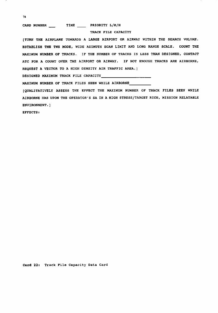
74
CARD NUMBER TIME - PRIORITY L/M/H
TP.ACK FILE CAPACITY
(TURN THE AIRPLANE TOWARDS A LARGE AIRPORT OR AIRWAY WITHIN THE SEARCH VOLUME.
ESTABLISH THE TWS MODE, WIDE AZIMUTH SCAN LIMIT AND LONG RANGE SCALE. COUNT THE
MAXIMUM NUHBER OF TRACKS. IF THE NUMBER OF TRACKS IS LESS THAN DESIGNED, CONTACT
ATC FOR A COUNT OVER THE AIRPORT OR AIRWAY. IF NOT ENOUG" TRACKS ARE AIRBORNE,
RBQUEST A VNCTOR TO A HIGH DENSITY AIR TRAFFIC AREA.]
DESIGNED MAXIMUM TRACK FILE CAPACITY
NAXIHIJH NUMBER OF TRAC%. FILES SEEN WHILE AIRBORNE
[QUALITATIVELY ASSESS THE EFFECT THE MAXIMUM NUMBER OF TRACK FILES SEEN WHILE
AIRBORNE SAS UPON THE OPEPATOR'S SA IN A HIGH STRBSS/TARGET RE”, MISSION RELATABLE
ENVIRONMENT.]
BFFECTS:
Gard 22: Track File Capacity Data Card

2.3.19. Mission Utility and Integration 2.13.9.1. PUrpOse
The purpose Of this test is to qualitatively assess the ovarall utility of the radar for the aesigned mission and the integration and compatibility of the radar performance parameters, co"trols and display within the airplane.
2.3.19.2. General
The mission utility and integration test is the most important test of tha saries. During this test, mission relatable intercepts and attacks are performed to qualitatively assess tha radar. The quantitative and qualitative assessments of the previous tests are used to support and justify the qualitative determinations made during the intercepta and attacka.
Utility refera to the overall usefulness of the radar as it is implemented, as an aid to the mission. The radar parameters muet match the expected operational needs. Integration refers to the way the radar has been blended into the entire airborne system. From the evaluator's standpoint this characteristic is intimately tied into the area of human factore.
The qualitative assessments in miSSiOn relatable scenarios specifically called for in the previous tests are also performed during these intercepta and attacks. Gare should be taken; however, to ensure that the evaluator does not g=t too involved in recording qualitative commente to the detriment of watching the progress of the intercept and evaluating the radar. A conscious effort should be made "ot to get too involved in looking for specifics on at least the first intercept and attack to ensure that an overall qualitative assessment ca" be made. A voica recorder ca" be used to maka comments without diatractinq the evaluator from the display or the outbound ru" ca" be used to record results.
Multiple runs should be performed using different radar modes end mode combinations in as many different types of attacks as possible supareonic ru"*, if appliC.EJudiZ assess the utility of the radar in'high closure rate intercepts). The most likely scenarios should be performed
first and others performed as flight time allows.
2.3.19.3. Instrumentation
Data carda are required for this test. A voice recorder is highly recommended.
2.3.19.4. Data Required
Record qualitative Co""ne"tS Co"Cer"i"g the utility and integratio" of the radar. Record the effecta of the parameters determined in previous tests during the intercepte and attacks as called for at the end of each test procedure.
2.3.19.5. Procadure
Place the target beyond the ranges found during the maximum detection range tests for the mode being used. Place the target 1,000 feet above the test airplane for the first ru". "se the most likely long range intercept mode for the first ru" and the rest in order of priority as time allows. "se a medium to wide scan angle limit and a long range scale with a two to four bar patter" to simulate a search for an inbound threat. Cal1 for the target to turn inbound and turn the test airplane towards the target. Use a mission relatable subsonic intercept speed for the first ru" (usually Mach (I-l) 0.85 to 0.9 for both the target and test airplane is adequate). It ie important to use enough speed, since the closure rate Will affect the evaluation of the detection range and update rats. Perform a normal intercept. optimizing the range scale, sca" angle limits, antenna elevation angle etc. until the target is confirmed and a" STT is acquired. Continue inbound and convert the intercept to a" astern attack of the target as the target continues to fly straight and level. "se the ACM modes during the conversion and eimulate the selection and firing of weapons, paying particular attention to the effects of the radar parameters and human factora upo" the tactice used for each weapo".
On later intercepte, try the other Long range detection modes for the initial detection and other possible combinations of modes while closing. In addition, perform some of the intercepta with the target at as low an altitude as safety permits, to Sssess the effects of the clutter environment. If two targets are available, use them both on at least one intercept and then split them onto two stations, switching from one to the other (three in a barrel) to maximize

76
the number of intercepta during the flight. If time, fuel and airepace permit, perform one supersonic intercept using A VS mode for initial detection, paying particular attention to the effectm of high closure rates. If time permita, allow the target to maneuver up to 30' and 5,000 feet (excluding 1,000 feet above or below the test airplane altitude) Off of the planned 'crack without informing the evaluator of the maneuver beforehand, to eimulate a moderately "jinking" target. Record qualitative commenta concerning the utility of the radar for the assigned mieeion, including the affects of the parameterm detennined during previoue tests andthe oveeall integration of the radar into the airplane.
2.3.19.6. Deta Analyais l nd Presentation
Relate the qualitative deficiencies noted to their effects llpon the performance of the intercepte and astern conver~ione. Note any limitations upon tactics imposed bythe radar parametere, utiuty or integration. As an exemple, the radar may not be able to detect a target at a range that allows the opoeator to set up and fire the weapons csrried et their maximum range. The radar should not be driving tactics. Use the applicable resulte from the pSViOUB tests to support the qualitative resulte.
2.3.19.1. Data Cards
A sample data tard ie peesented as tard 23.

77
CARD NUMBER _ TIME _ PRIORITY L/M/"
MISSION UTILITY AND INTEGRATION
[POSITION THE TARGET ON T"E NOSE AT _ NM AND 1,000 FEET ABOVE THE TEST AIRPLANE.
TURN THE TARGET AND TEST AIRPLANE TOWARDS EAC" OT"ER, ACCELEPATING TO"-_. "SF, THE
MODE, WIDE SCAN ANGLE LIMIT, _ BAR PATTERN, AND NM RANGE SCALE. GAIN
AN STT AND CONTINUE INBOUND. SIMULATE A LONG RANGE MISSILE LAUNC", THEN A MEDIUM
RANGE "EM-ON S"OT. OFFSET THE TARGET AT 10 NM AND PERFOR" AN ASTERN CONVERSION.
USE THE ACM MODES DURING THE CONVERSION. SIHULATE ASTERN MISSILE AND GUN ATTACKS.
MAKB NOTES CONCERNING THE MISSION UTILITY, INTEGRATION AND T"E EFFECTS OF RADAR
PARAMETERS. REPEAT WIT" THE TARGET AT _ FEET AGL. REPEAT THE TEST WIT" THE
TARGET AND TEST AIRPLANE AT H- - AND IN THE VS MODE FOR INITIAL DETECTION.)
NOTES:
Gard 23: Ait-to-Air Misaion Utility And Intagration Data Card

78
2.3.20. Introduction to Advanced Air-toAir Radar Test Techniques As mantioned in Chapter 1, only the most rudimentary form of the air-W-air radar teet techniques are preeented in thie book. Chapter 1 details the reasons for thie format; however, in lEUly applicationa, more rigor, accuracy and documentation of resulta are required. Table 1 outlines additional instrumentation and assets which are typically applied inthese more advanced
teete. The purpoee of this table is merely to emphasize the existence of these advancad techniques. Further, thie list is not exhaustive. Many innovative "eee of aseete and instrumentation exist. It is hoped that the exemples provided leave the reader with a taste of how the test cari be made more rigorous through the judicious "se of instrumentation. In application; the user must refer to the more advanced documents referenced in Chapter 1 or so1lcit help from more experienced testera.
Table 1: Additional Assets or Instrumentation for use in Advanced Air-to-Air r>arlar Tell+. _ .__ __ _ _ _ _ _
Test Additional Aaeet or Purpoee/Benefit Instrumentation 1
Preflight and Digital Recorder. Typically record= data from data bus Built-in- on which radar passes the BIT Tests. results. Alloua precise
documentation of test results. Ueually used in conjunction with fault insertion tests.
Vidao recording of Provides automatic recording of what dieplay. the operator sees as a fault atatus
is displayed.
Controle and Vidao recording of Alloue automatic documentation of Displays. dieplay. display problems as well as post-
flight analysis and evaluation.
Cockpit mock-upe, Typically used for Fn-depth ground reconfigurable tests of human factors and in cockpits and iterative cockpit design. virtual cockpits.
Digital recording Can be used as a means of precisely Of operator recording operator selections to actions. document noted problams and as a
meane of performing operator tasking analysis.
Stan Rate. Digital recording In some eyatems the sweep position of radar data. cari be digitally recoeded as output
of a eca.* converter. In this case the instantaneous as well as the average scan rate cari be calculated as required.
Time stamped video Even in the absence of digital data, recording of the instentaneous and average scan display. rates cari be derived using
appropriately time stamped video.

Table 1: Additional Assetm or Instrumentation for use in Advanced Air-+x-Air Radar Teste (Continued)
Sean Angle Limits.
Digital Recording The test cari be made more accurate by of aircraft heading recording the precise target and test and poeition for aircraft location, precise test both the target and aircraft heading (thase parameters test aircraft, time are either derived and recorded on- stamped video board or using a space positioning recording of range a* appropriate) as well ae
preciee time. The radar display is
Elevation Similar to scan Similar to scan angle limita except Angle Limita. angle limita except the vertical angles to the target are
vertical angles are
onboard or range space positioning heading and turning data) are geometrically reduced to
radar data derive the crossing rate of the including STT target at the time that the radar positions and track data indicates that the radar bas
bilization

Table 1: Additional Asset or Instrumentation for use in Advanced Air-to-Air Radar Teste (Continued)
Digital recording The test and target aircraft of time stamped locations are geometrically reduced radar detections. to provide actual, time stamped Video recording of locations of the target in radar time stamped radar dioplay. Time stamped test and target aircraft the targat recorded on the radar locations. dieplay and digitally recorded radar
detection data. Often, the real 'cime propagation performance is predicted on inatrumented ranges for the
measurement of frequency of the test radar and Caeual interference is recorded on
interference. the aircraft using special instrumentation. Sometimes thia
groundspeed, course and altitude.
target aircraft correlated to the displayed radar groundspeed. Video information at breakout. recording of the time stamped radar display.

Table 1: Additional Asaets or Instrumentation for "se in Advanced Air-to-Air Radar Tests (Continued)
Test Additional Aaeet or Purpose/Benefit Instrumentation
Blind Speeds. Digital recording High accuracy ae well BB high update of precise time and recording rates are necessary to stamped target and get accurate target cloaure ratee teet aircraft during maneuvere. Can be derived heading and onboard or on a space positioning groundspeed. Video range. Time correlated target and recording of the teat aircraft parametere are compared time stamped radar to the geometrically derived closure display. rate. This is compared to drop-outs
in the radar display. Emphaeis ie placed upon the statistical significance and repeatability of the blind speede.
Air Combat Digital recording For complete documentation, this teat Modes. of precise, time requiree preciee documentation of a11
stamped test and target and test aircraft dynamics and target aircraft locations, which are then time poeitione, rates correlated with radar data and the and accelerations; operator displays. digital recording of time etamped radar data, time etamped video recording of the radar and head up dieplay.
Falee Alarm Ground radar Radar detection data, are time Rate. coverage and time correlated with the ground radar
stamped recording detection data to verify or diaprove of the entire radar the existence of actual radar search volume. Time tatgets. stamped video recording of the radar display. Digital recording of time etamped radar detection data.
Track File Video tecording of Sinca the test simply varifies the capacity. the radar display. maximum track file number, the
recording of the radar display provides eome added documentation.
Hîasion Digital recording This test requires the largeet amount Utility and of precise, time of data to completely document the rntegration. stamped test and results. It is during this test that
target aircraft most of the unexpected problems are poeitions, rates found. In anticipation of having to and accelerations; document these daficiencies, maximum digital recording instrumentation and range support are of time stamped sometimes brought to bear in cage radar data; time unforeeen data are required in poet- stamped video flight analysis. recording of radar and head up display.

82
2.4. AIR-TO-GROUND RADAR TEST TECHNIQUES
2.4.1. Stan Rate
2.4.1.1. Purpose
The purpose of this test is to determine the average radar scan rate and its effect upon the utility of the radar presentation.
2.4.1.2. General
Host air-to-ground radars operate in a single bar, raster scan format. The rate at which the antenna moves from aide to side determines the scan rate. since the antenna must stop at each side and since the moving parts bave some inertia, the actual scan rate varies through the scan and as the scan angle limita are changed. The important characteristic for the air-to-ground radar is hou often the target and the map display is updated and 80 an average scan rate over a number of scans in each scan angle limit setting Will be used.'
SCZ,ll rate cari affect SeVeral radar performance factors. A quick scan rate is desired to provide a rapid update of the target position and the radar navigation display. If the update is too slow, the airplane's position on the radar map preeentation Will change between scans requiring mental integration. In addition, during very low level flying, the radar presentation may change drastically between scans. A very rapid display update alleviates these problems. The update rate must also be rapid enough to provide quick and accurate position updates of the target during the final seconds of the ettack. This requirement Will vary depending upon the accuracy of thé navigation system used (drift), accuracy requirements of the weapons used, and the accuracy with which the radar cari designate a target at longer ranges. Unfortunately, there are limits to the scan rate that cari be used. The limiting factor is usually the number of radar hits required to build a consistent radar display. Too few hits results in an inconsistant and washed out display. Once the requirement for adequate mapping quality is obtained, the scan rate should be left at the
highest possible rate to update the display as frequently as possible. Mapping quality and consistency tests Will be discussed later.
2.4.1.3. Instrumentation
A stop watch and data cards are required for this test. A voice recorder is optional.
2.4.1.4. Data Rmquired
Me*sure the time for tan complete radar scans (one side to the other and back) at each scan angle limit setting. Record qualitative commenta concerning the effects of the display update rate upon the mapping display utility and the target display during mission relatable attacka.
2.4.1.5. Procedure
While on the ground, use a stop watch to measure the time for the sweep to move from one sida of the display and back for ten full sweeps. Perform the test at a11 scan angle limit settings and repeat for one setting while airborne to confirm the ground test. If a disctepancy occurs between the ground and airborne data, repeat for a11 scarl angle limits. While performing attacks at mission relatable speeds, evaluate the effect the update rate has upon the utility of the display for radar navigation. During the final phases of the attack, note the effect the update rate has upon the operator's ability to accurately maintain the designator or cursors over the target position.
2.4.1.6. Data Analysis and Presentation
The scan rate is calculated using the following relationship:
The mapping quality and consistency test to be discussed later Will evaluate whether the scan rate is slow enough to provide a consistent mapping display. The test discussed in this section is designed to evaluate whether the rate is quick enough to provide an update rate of the display adequate for a11 mission relatable scan angle limit selections and attack profiles. Relate the update rate to the necessity for near real-time

navigation and target positioning data during high spead, lbw lave1 ingress to tha target when tha radar horizon is very short and to tha neceesitv to perform terminal target updates bëfore delivering ordnance.
2.4.1.1. Data Cards
A sample data tard is presented as tard 24.

84
CARD NUHEER TIME PRIORITY L/M/H - -
AIR-TO-GROUND SCAN RATE
[RECORD TIME FOR 10 COMPLETE SCANS.)
[RECORD QUALITATIVE COMMENTS ON THE MAP UPDATE RATE AND TARGET POSITION "PDATE
RATE.]
TEST AIRPLANE SPEED
TEST AIRPLANE ALTITUDE
SCAN ANGLE LIMIT_
RADAR MODE
TYPE ATTACK FLOWN
EFFECTS:
Gard 24: Air-ta-Ground Stan Rate Data Card

2.4.2. Stan Angle Limits 2.4.2.1. Purpos.
The purpose of this test is to determine the sca" angle limita of tha radar and their effects upo" the utility of tha radar search volume.
2.4.2.2. General
Host air-to-ground radars operate in a single bar, raster ~CL" format and oftan have aeveral operator selectable antenna scan angle limita. The largest selection is usually bounded by the physical *ca" angle limita of the antanna. The bounds are often set by the physical limita of the antenna against the "ose cane faring covering the antenna or eve" by lina of sight interference between the radar beam and airplane structures. In addition, when extremely wida limita are used, the tima that the antanna ca" epend at a"Y specific bearing within the search volume is reduced for a given display updata rate. When a lower sca" angle limit selection is made in order to concentrate tha seatch volume, the operator is often able to slew the centar of the eearch volume within these maximum left and right limits. FOT thesa reasons, the maximum sca" angle limits become critical and should ba measured.
The maximum limita should be avaluatad while performing radar navigation to ensure enough area is displayed to allow orientation on a tactical chat and during searches for targets of oppottunity to ensure enough volume is searched such that the radar does "ot limit the airplane in its area of attack. During attacks, the maximum angle Off the "ose to the targat expected in mission ralatable tactics muet be ueed to evaluate tha eca" angle limite while using the smaller angle se1ections. The smaller selactions are used after the initial position of the target is determined to allow concentrating the radar on the target area and the intended flight path. The range and number of selections must be suitabla for the expected scenarios for which the airplane is designed to operate.
2.4.2.3. Instrumentation
Data cards are required for this test with a" optional voice recorder.
2.4.2.4. Data Required
Record the heading of the test airplane with a target of opportunity "ver the "ose and jus+ at the edge of tha dieplay for eech sca" angle setting for both tha left and right limit. Record qualitative comments concarning tha utility of the maximum SE~" angle limit and the smaller angle selectione.
2.4.2.5. Procedura
Cho"se a terget of opportunity at least 15 nm ahead of the test airplane to allow the test turn to be completed without significantly affacting the geometry of the target. If the display is truncated at the sca" angle limit selected, the range must be inside of the truncated area. Place the target just to the right or left of the "ose of the test airplane with the sweep centered on the "ose. Tur" the test airplane slowly toward the target, marking the test airplane heading as the "ose crosses the target bearing and as the target passes off of the radar display. Repeat to the other side and for a11 sca" angle limit selections. Qualitatively evaluate the effect of tha maximum 8can angle limit upon tha utility of the radar map display for orientation on a t,actical map, for the radar's utility in finding targets of opportunity "ver a wida area and for any constraints that the limit may pose upo" attack tactics by restricting the maximum angle off of the "ose during ingress to the target. Assess the utility of the smaller angle limite for concentrating the radar on a narrower area as the target position and tha flight path to it are narrowed.
2.4.2.6. Data Analysis and Présentation
Subteact the test airplane heading while tha target ie over the test airplsne "ose from the heading as contact is loet for the left/right at each scan angle limit setting to determina the measured *ca" angle limita. Use the measured limits deficienci:s
supporting data where are noted in the
qualitative evaluation of the sca" angle limita. Relate problems noted with tha maximum sca" angle limita to tha utility of the map display for area orientation, finding targets of opportunity and to the limitations imposed upo" inbound tactics by the maximum angle off the "ose to the target that ca" be used while still illuminating the target. Relate the number and limits of the smaller angle selections to the

86
desirability of narrowing the ecan volume as the targat position is rafinad.
1.4.2.1. Data Cards
A aample date tard ie presented as tard 25.

87
CARD NUMBER - TIMB _ PRIORITY L/M/H
AIR-TO-GROUND SCAN ANGLE LIMITS
[CHOOSE A TARGET OF OPPORTUNITY JUST TO THE LEFT OR RIGHT OF THE NOSE AT 15 NM.
TURN TOWARDS THE TARGET. RECORD THE TEST A/C HEADING AS THE TARGET PASSES THROUGH
THE NOSE AND WHEN IT IS LOST FROM THE DISPLAY DURING THE TEST AIRPLANE TURN. REPEAT
TO THE OTHER SIDE AND FOR EACH SCAN ANGLE LIMIT SELECTION.]
RADAR MODE AZ LIWIT NOSE LEFT/RIGHT LOST TARGET
SELECTION (L/R)
[RECORD QUALITATIVE COMMENTS CONCERNING THE UTILITY OF THE MAKIMUM SCAN ANGLE FOR
RADARMAPPING AND ORIENTATION, ITS EFFECT UPON TACTICS (MAKIMUMANGLE OFF OF TARGET)
AND FINDING TARGETS OF OPPORTUNITY. RECORD COMMENTS ON THE UTILITY OF THE RANGE AND
NUMBER OF THE SMALLER SELECTIONS.]
SCAN ANGLE LIMIT SELECTION
TARGET RELATIVE BEARING
TYPE OF ATTACK
EFFECTS:
Gard 25: Air-to-Grand Stan Angle Limits Data Card

88
2.4.3. Elevation Angle Limits 2.4.3.1. Purpose
The purpcss of this test is to determine the elevation angle limite of the radar antenna and their effects upo" the utility of the radar saarch volume.
2.4.3.2. General
As with sca" angle limits, the elevation angle limita of the radar are often established by the physical limita that the antenna ca" be slewed up or down. These limita ca" be physical, caused by space or gimbal constraints withi" the "ose cone or by interference between the radar beam and the airplane structure, although the latter is lese likely for the elevatic" limite than for the asimuth limita. Elevation angle limita are important tc air-to-ground radars since they limit the maximum pitch tnaneuvers the test airplane ca" perform and still maintain radar contact with the target. The airplane must be able tc maneuver as much as possible in the terminal attack phase to defeat surface defenses while at tha same time prosecuting the attack. In addition, many weapon deliveries require pitching mansuvers. Finally, the lcwer limit will affect the minimum range that the airplane ca" close on the target without losing radar contact. Mcst modes" radar antennas bave a gimbal limit of approximately 60' above and below the airplane centerline (the exact centerline used varies from airplane to airplane as with the air-to-air platforme). The limita should be measured and then the effacts of these limita shculd be evaluated during mission relatable simulated or actual weapons deliveries, choosing the deliveries with tha largest variations in pitch for the evaluation. Mission relatable evasive maneuvering (jinking) should also be performed inbound to the target.
2.4.3.3. Instrumentation
Data carda are required for this test with an optional voice recorder.
2.4.3.4. Data Required
Record the antenna elevation angle displayed on the radar display as radar video is lest in the vicinity of the oursors designating the center of the radar sca" volume.
2.4.3.5. Prccedure
Begin the test at a medium altitude, 15,000 feet AGL or above is typical, with enough airspeed tc perform a slow pitch "p to the expected theoretical elevation angle limits and to perform a recovery tc leva1 flight. Chccse a target of opportunity on the "ose of the airplane at 1east 7.0 "m away. Designate the target for geostable tracking using the curscr designator, if the radar is capable, narrowing the scan angle limita to a narrcw se1ection. If the radar doas not automatically Select the rangs scale, Select a scale that just includes the target. Perform a slow pitch up until the radar display disappears over the target area or until tracking breaks lock. Record the antenna elevation at the time. Ae-establish target tracking and slow the test airplane. Begin a pitch over, looking for the same indications as above. Discontinue the test if any aircraft limita are reached and insure enough altitude is available for the test aircraft tc perform a safe recovery from the nose-down attitude. Co"sult a11 availabla aircraft performance data before attempting the iYIa"e""er. Record the antenna elevation as above. During mission relatabla attôcks, record the effects the above antenna elevation limite bave "pc" ingress and weapo" delivery tactics.
2.4.3.6. Data Analysis and Prssentation
Use the displayed antenna elevation at the tFme that radar detection is lost on the target of opportu"i.ty as the elevation limits. Relate the elevation limita to the restrictions that they place upo" jinking and "pc" delivery tactics while maintaining target radar detection.
2.4.3.7. Data Cards
A sample data tard is presented as tard 26.

CARD NUHBER _ TIRE _ PRIORITY L/Y/H
AIR-TO-GROUND ELEVATION ANGLE LIMITS
[CLIMB TO FEET AGL, INCPEASE SPEED TO _ KIAS ARD CHOOSE A TARGET OF
OPPORTUNITY ON THE NOSE AT 20 NM. DESIGNATE THE TARGET USING GEOSTABLE CURSORS AND
NARROW THE DISPLAY. SELECT THE SHORTEST POSSIBLE RANGE SCALE WHICH STILL DISPLAYS
THE TARGET. PITCH UP UNTIL THE TARGET IS NOT DETECTED AND RECORD THE ARTENNA ANGLE.
SLOW TO - KIAS AND REPEAT IN A PUSH OVER.]
LOWER LIMIT UPPER LIMIT
(QUALITATIVELY EVALUATE THE EFFECTS OF THE ELEVATION LIHYTS UPON INGRBSS TACTICS AND
KEAPON DELIVERIES.]
TACTIC OR DELIVERY
NANEUVER
EFFECTS:
Gard 26: Air-to-Ground Elavation Angle Limite Data Card

90
2.4.4 Antenna Stabilization Limits 2.4.4.1. Purpwe
The purpose of thie test is to evaluate the ability of the radar antenna to maintain stabiliratio" during msneuvering flight and to determine ite effects upon ingress and weapo" delivery tactics.
2.4.4.2. General
A6 diecuseed in the radar theory section, many radar antennas are gyroscopically or inertially stabilized in relation to the horizon within the boundaries of the ecan and elevation limita; however, there are rate limitations to which the airplane ca" be maneuvered before this stebilization is degraded. The radar should be designed euch that these boundsries are beyond the maneuvering limita of the host airplane for a11 three maneuvering axes (roll, pitch and yaw). Meaauring y*w ratea in flight without instrumentation is quite difficult, step inputs to the maximum allowable at a mission relatable maneuvering epeed Will be used instead of an actual yaw rate measurement. The loes of etabilization usually manifesta itself as a degradation of mapping and detectio", atrobing and other perturbations of the general radar dieplay. The minimum criteria ie whether the display is still adequate for radar navigation and area orientation, 88 well as target detection and accurate terget designation. Combined roll, pitch and yaw maneuvers ca" bave their ow" effects upon the dieplay and as such should also be evaluated.
2.4.4.3. Instrumentation
Data cards and a stop watch are required for the teet with a" optional voice recorder.
2.4.4.4. Data Required
Record the time to go from 40' "ose low to 40' "ose high at a constant g rate up to the g limit of the airplane. Record the rime to roll 360' at increasing etick deflections. Record the percent of rudder throw used to achieve increasing Yaw rates. During a11 maneuvers, make qualitative comment6 on the affects that the maneuvers bave upo" the radar display and detection performance. Record the same qualitative coiNne"ts during rolling push-overs and pull-ups. Record
qualitative comments concerning the effects of the antenna stabilization limita (if any are found) during mission relatable ingress evasive maneuvera and while performing mission relatable weapo" deliveriee.
2.4.4.6. Procedure
Climb (approxim~tely
a medium altitude 15,000 feet AGL ie
typical) and set a" airepeed that allows for aafe, high g maneuvers (usually 300 to 400 KIAS is adequate). Establish a normal search or radar mapping mode. Select a ecan angle limit at ~~t~;;mately 30' to 40' and aet the
elevation to optimize the display around a point 30 to 40 nm ahead of the airplane. Center the display on the "ose. Maneuver to 50' "ose low and emtablish a Zg pull-up to 50' nose high at a constant 2g rate. Mark the time whila passing from 40' "ose low to 40' nose high. Note any degradation in the radar display, including any 10s~ of detection at a"Y ranges that were praeent before maneuvering, atrobing or spoking on the display or any other effects. If the elevation angle limits are lees than 50', the" a smaller maneuver Will bave to be performed to maintai" contact with the target. Repeat the teet at increasing g levele until degradation is noted or the g limit of the airplane is reached.
Center the sca" volume 20' off of the "088. Roll the airplane 360' at 114 stick deflection, noting the time to complete the roll and any degradation in detection or the display. Repeat at 112, 3/4 and full stick deflactio" if the airplane limita allow. With the sca" volume again centered on the "ose, perform a step input of the rudder at 114 deflection. Note any degradation of datection or the display. Repeat at 112. 314 and full rudder deflections if the aircraft limits allow. If no degradation is noted while performing the tests above, perform a series of rolling push-overs and pull-ups at increasing g rates until the limita of the airplane are reached. Again, look for degradation in detection or the radar display. During ingress evasive maneuvers and weapo" delivery maneuvers, note the effecte upo" tactics of the limita found above.
2.4.4.7. Date Analysis and Presentatio"
Divide the time to perform the pitch up maneuvers into the 80' covered to obtain the average pitch rate. Divide the time

91
to roll into 360' to get the average roll rate. If no degradation is noted within the maneuvering limite of the airplane during single axis or the multFp1e axia maneuvera, then the stabilization limita are probably setiefactory. If degradation is noted, it should be related to the limits that this degradation imposes upon tactics. The amount of limitation depends upon the axia involved (a pitch axis limit of 29 on an 8g airplane would be more serioue than a yaw axis limit of 114 rudder deflection) and the level at which the degradation ie noted. These limitations ehould be verified during miseion relatabla attacks.
2.4.4.6. Data Cards
Sample data cards are provided as tard 27.

CARD NUMBER - TIMZ _ PRIORITY L/M/H
AIR-TO-GROUND ANTENNA STASILIZATION LIMITS
[CLIMB TO _ FZZT AGL, SET KIAS AND SELECT A SEARCH OR MAPPINO MODE AND A 30’ -
TO 40' AZIMUTH LIHIT. OPTIMIZE THE ANTENNA ELEVATION FOR A 30 TO 40 NM RANGE MAP
DISPLAY AND SELECT A RANGE SCALE TO COVZR ALL THE RADAR VIDEO PROVIDZD. PITCH DOWN
TO 50’ LOW AND PULL-UP AT ZC TO 50' NOSZ HIGH. TIHZ 40' LOW TO 40' HIGH. NOTE ANY
DEGRADATION. RZPEAT AT INCRZASING 0 RATES.]
[CENTZR THE SCAN VOLUME 20' OFF OF THE NOSZ. ROLL THE AIRCRAFT AT 1/4 STICK
DZFLZCTION. NOTE THE TIME TO ROLL 360' AND DEGRADATION. RZPZAT AT 112, 314, AND
PULL DZFLZCTION.]
TIMF, TO ROLL DEGRADATION
tard 27: Air-to-Ground Antenna Stabllization Limita Data Carda

AIR-TO-GROUND ANTENNA STABILIZATION LIMITS
[CENTER THE SCAN VOLUME ON THE NOSE. PROVIDE A STEP INPUT OF RUDDER AT 1/4
DEFLECTION. NOTE DEGRADATION AND RBPEAT AT 1/2, 3/4 AND FULL DEFLECTION.]
RUDDER INPUT DEGRADATION
(PERFORM EASY ROLLING PUSH-OVERS AND PULL-UPS, NOTING ANY DEGRADATION. REPEAT AT
INCRBASING G LEVBLS UNTIL DEGRADATION IS NOTED OR THE AIRPLANE LIMITS ARB REACHED.]
DESCRIBE THE MANEWER (CONTROL DEFLECTIONS, G LEVBLS ETC.):
DEGRADATION:
[EVALUATE THE ANTENNA STABILIZATION LIHITS DURING MISSION RBLATABLE EVASIVE
MANEUVERS AND WBAPON DELIVBRY MANEUVBRS.]
TYPE OF MANEUVERS
DEGRADATION:
Gard 27: Air-to-Ground Antenna Stabilization Limita Data Cards (Continued)

2.4.5. Minimum Range
2.4.5.1. PUrpclS.
The purpose of this test is to determine the minimum range of the radar and ite effects upo" weapo" delivery tactice.
1.4.5.2. General
The theoretical minimum radar range ia discussed in the radar theory section. Thie is the absolute minimum range possible; however, the minimum range ia usually eomething greater. The display ie a" important factor, ZLB in the air- to-air minimum range. For a PPI display, the mapping video becomes very cluttered and often becomes a block of aolid video close to the "otch of the V from which a target canot be resolved. Minimum range is ctitical in air-to- ground radars eince highly accurate and feequent target position updatee are required to place conventional ordnance on small tactical targets. The final target update is often the difference between a hit and a wide miss.
Note should be take" ae to exactly what range ie being measured while performing the minimum range test in carder to properly interpret the reeults. The radar range ie the line of sight from the radar to the target and ca" be envisioned as the hypotenuse of a triangle. Ona of the remaining sides of the triangle is then the altitude of the test airplane above the target. Thia implies that the minimum range measured ca" "ever be less than the altitude above the target. In addition, the lower antenna elevation angle fixes one of the adjacent angles in the line of sight, height, minimum range triangle 80 that the minimum range that ca" be meaeured becomes aven greater than the test altitude above the target. FOT these reaso", the test should be performed at es low a" altitude a8 possible within the limitations of safety. 200 to 500 feet AGL are usually chose" for test purposes. Gare muet be taken to ensute that the effects of the lowee elevation angle limita discussed earlier are net confused with the effects of the radar minimum range.
2.4.5.3. Instrumentation
Data carda and a" optional voice recorder are tequired for this test.
2.Q.5.4. Data Required
Record the altitude and airspeed of the test airplane, target elevatlon, antenna elevatio" at the time detection is lest on the radar dieplay and the displayed radar range. Record the time between 106s of detection and ovarflight Of the target. Make qualitative commente concerning the effects that the minimum range has upo" the final target position updates.
2.4.5.5. Procedure
Descend to the teet altitude. Choose a target of known altitude and designate it using the radar cursors. use geostable curaors if available. If "ot, adjust the antenna elevation angle to optimize the target display. Proceed inbound to the target at a constant altitude. Continue to observe the radar display of the target as it converges to the bottom of the display. Louer the range sale to the minimum possible to dieplay the target if the radar doae not downscale automatically. Just as radar contact is lest, start the stop watch, record the displayed range to the target, altitude, airspeed and antenna pointing angle. Mark the elapsed time as the target is overflown. During mission relatable attacke, assess the effecte that the minimum range has upo" the ability of the radar to provida accurate, final target updates.
2.4.5.0. Data Analysis and Presentation
Check the antenna pointing angle (Lt the time detectio" was lest to determina if it was at a" angle less than the lower antenna elevation lirait. If it was at the limit then assume that the minimum range ie limited by the lower antenna elevation angle. If it wae not at the limit, use the displayed radar range as the minimum radar range. use the airspeed and time to overflight to confirmthe radar derived range. Relate the minimum range to the likelihood that the target position will change in the case of a moving target, or that the last measured position Will drift due to navigational errors for stationary targets, causing a reduction in weapo" delivery accuracy.
2.4.5.7. Data Cards
A sample data tard is provided as tard 28.

CARD NUMBER TIMB PRIORITY L/M/H - -
AIR-TO-GROUND MINIMUM RANGE
[DESCEND TO _ FEET AGL. SET _ KIAS. DESIGNATE A ENOWN TARGET WITH THE
GEOSTABLE CURSORS AND HEAD TOWARDS IT. WATCH FOR LOST DETECTION. RECORD THE DATA
BELOW.]
TARGET
ALTITUDE OF TARGET (MSL)
ALTITUDE AT LOSS (MSL)
AIRSPEED AT LOSS
RADAR RANGE AT LOSS
ANTENNA ELEVATION
TIME FROM LOSS TO OVBRFLIGHT
(QUALITATIVE COHMENTS CONCERNING THE EFFECTS OF THE MINIMUM RANGE UPON LAST SECOND
TARGET POSITION UPDATES.]
TYPE DELIVERY
EFFECTS:
Gard 28: Air-to-Ground Minimum Range Data Card

2.4.6. Dowler Beam Sharpened Notch Wcith 2.4.6.1. Purpose
The purpose of this test is to determine the angular width of the DBS notch over the "ose of the aieplane and the effect that this notch has upo" ingress and attack tactics.
2.4.6.2. GenerAl
The theory behind the DES mode and the tea~~o" that the notch existe "ver the "ose of the airplane is explained in the radar theory section. The notch is important since it limita the airplane from flying directly to the taeget while using the DBS mode. The effect that this has upon tactics depends on the width of the notch. For radars that fil1 the "otch with real beam video, the break betwee" the two LB usua11y apparent and easily dafined. Ths notch is still important is this case aince the real beam filler doee "ot bava the resolutio" of the DBS picture and still requires maneuvering sway from the direct inbound path to use the DBS mode on the target area. Typically, the notch is narrow enough that the "SS display ca" be centered on the "ose of the airplane and the notch will be completely enclosed within the dieplay with DES video on either side, simplifying the measurement of the notch width.
2.4.6.3. Instnuentation
Data carda, a ruler and an optional voice recorder are required for this test.
2.4.6.4. Data Required
Record the angular width of the B *ca" format used for the test and mark on the edge of the data tard both sides of the DBS display and both eides of the notch. During mission relatable ingresses and attacks, record qualitative commente on the effect that the notch hae upo" ingrese tactics.
2.4.6.5. Procedure
With the airplane flying straight and level at a medium altitude, tenter the DBS display "ver the "ose at approximately 20 to 30 nm and allow the dieplay to build. Hold the data tard up to the display, perpendicular to the DBS notch. Mark on the tard the left and right sida of the display and the left
and right side of the notch. Perform mission relatable ingresses and simulated attacks ueing the DES mode. Record qualitative commenta concerning the effecte upo" tactics of not being sble to fly directly to the target.
2.4.6.6. Data Analysis l nd Presentation
use the ruler to determine the dietance betwee" the two tick marks on the data tord that represent the edges of the DBS display and the distance between the two tick marks that represent the edges of the notch. "se equation 20 to find the DBS notch width.
Relate the width of the notch to the requirement to zigzag to the tatget to kasp it out of the notch and to the raquirement to eventually put the targst in tha notch and rely upo" the target stored position juet before over-flying the target.
2.4.6.1. Data Cards
A sample data tard is provided ae tard 29.

97
CABD NUWBER - TINE _ PRIORITY L/M/H
DES NOTCH WIDTH
[CLIHB TO _ FEET MSL. SELECT DBS AND CENTER THE DBS MAP ON THE NOSE AT 20 TO
30 NM. HOLD THE DATA CABD UP TO THE DBS DISPLAY, PERPENDICULAN TO THE NOTCH, AND
MARK THE EDGES OF THE DISPLAY AND OF THE NOTCH.]
DISPLAY ANGULAB WIDTH SELECTED
[RECORD QUALITATIVE CONMENTS CONCEBNING THE EFFECTS OF THE NOTCH UPON MISSION
BELATABLE INGBBSSES AND ATTACKS.]
EFFECTS:
Gard 29: Doppler Beam Sharpened Notch Width Data Card

2.4.7. Range and Bearing Accuracy airplane altitude and heading. During mission relatable inoreasea and Bimulated weapo" deliverces, note the
2.4.7.1. Pu-pose utility that the read out of target bearing and range provides ** a" *id for
The purpose of this test is to determine flying to tha target and delivering how accurately the radar ca" determine weapons. the bearing and range to * radar target and the effect that thie accuracy hae 2.4.7.6. Dalta Analysie and upon ingresa and ettack tactics. Presentation
2.4.7.2. Qeneral
A preciae range and azimuth accuracy test requires external Bpace positioning d*t*; however, a" approximate check cari be obtained by visually marking on top of a Burveyed point and taking the radar derived range and bearing to another Burveyed target. The pilot's mark on top technique is critical to this test and the test should be flou" et *B low *" altitude *B safety permit*. An approximate rule of thumb for mark on
top *cIXr*cy for an experienced evaluator ie half of the altitude above the mark on top point. Range and bearing accuracy 1s important since it affects the utility of the vectora that the pilot gets from the radar as wall as the target position input to the weapons delivery computer and to tha seekers of stand-off weapons.
For radar* that provide a relative bearing to the target, add a right target bearing to the test airplane heading to get the magnetic bearing to the target. Subtract a left bearing to the target to get the magnetic bearing to the target. "le the difference between the known latitudes and longitudes of the flyover and target points to calculate the north-aouth and east-west range differencee. Use thesa rangea to salve for the hypotenuse of a right triangle. This is the approximate range between the fixes. The interna1 angles ca" then be solved for and added or subtracted from 0', 90'. 180'. 270' or 360' to obtain the approximate truc bearing between the point*. Finally, variation is added to the truc bearing to obtain magnetic bearing.
2.4.7.3. Instrumentation
Data Cards and a" optional voice recorder are required for thie test.
2.4.7.4. Data Rsquired
Record the test airplane altitude, heading and radar derived bearing and range to * surveyed radar target as the test airplane mark8 on top of another surveyed point. Record qualitative comment* concerning the utility of the radar derived bearing and range to the target during mission relatable ingresses and Bimulated target attacks.
Anm=the difference in nautical miles between the surveyed points along the north-south or east-west ai*.
2.4.7.5. Procedure
Before the test flight, Select a visual target in the test area that ha* a surveyed latitude and longitude and * Burveyed radar target at 15 to 20 Nn away from the visual target. The radar target doee not have to be in the test are*. Descend to the test altitude. Fly a heading to the target that places the target within the radar Bearch volume and keep the cursor~ as close to the target as possible. Perform a fly-over of the visual target. At fly-over, mark the bearing and range to the radar target, and then the test
A,,=the difference between the latitude of the surveyed points in minute*. A,=the difference between the longitude of the surveyed points in minutes. Lat=the numerical *Ver*ge of tha latitude of the two surveyed points in degrees. M _=actual magnetic bearing from the fly-over point to the radar target. T,,=actual true bearing from the fly-over point to the radar target. V=magnetic variation.
The difference between the actual and measured bearing and range are the bearing and range errer. Relate the hearing and range errer to the utility of the radar derived target position for

navigating to the target and for input to standoff weapoqs.
1.4.7.7. Data Cards
A sample data csrd is presented as tard 30.

CARD NUHEER TIME PRIORITY L/M/H - -
AIR-TO-GROUND RANGE AND BEARING ACCWACY
[OVBRFLY THE "ISUAL POINT AT _ FEET AGL AND _ KIAS. DESIGNATB THE RADAR TARGBT
BEFORE FLY -0VER.l
"ISUAL FLYOVER POINT
RADAR TARGET
BEARING/RANGE /
HEADING
ALTITUDE
[QUALITATIVELY EVALUATE THE "TILITY OF THE BEARING/RANGE ACCURACY FOR INGRESS
NAVIGATION AND TARGET DESIGNATION FOR STAND-OFF WEAPONS.]
EFFECTS:
tard 30: Air-to-Ground Range And Bearing Accuracy Data Card