1 new ignition systems - publikationen.bibliothek.kit.edu
TRANSCRIPT

1 New Ignition Systems
1.1 Spark-based Advanced Ignition Control for Future Diluted Gasoline Engines
Ming Zheng, Guangyun Chen, Jimi Tjong, Liguang Li, Shui Yu, Xiao Yu, Zhenyi Yang
Abstract To meet the mandatory CO2 emissions regulations in the future, current gasoline en-gines require significant work for efficiency improvement. One critical part of combus-tion optimization is to improve the spark ignition process, especially for the engines that utilize charge dilution concept incorporated with strong cylinder flow. Such high efficiency combustion process requires the ignition systems to effectively ignite the mixture and secure the flame kernel until developing to self-sustainable propagation. In this paper, the extent of spark stretching and the ability to withhold from restrike in high-speed flow are investigated for various sparking strategies. A thick plasma chan-nel that is generated by boosted glow current is less prone to be blown off by the strong flow, consequently, the restrike frequency is lowered. In comparison with a low current long lasting spark generated by the dual-coil continuous discharge strategy, the boosted current strategy can lead to a faster flame kernel growth. Single-cylinder en-gine experiments indicate that the combustion phasing controllability and the stability of lean/diluted engine operation can be improved by using the boosted current ignition strategies with conventional spark plug. Extensive engine test results indicate that the multi-core ignition can better control the gasoline combustion and extend the operable limits of lean/diluted engine combustion, compared with single-pole ignition for low to medium engine loads. Experimental results indicate that the multi-core ignition strat-egy, even with lower current on each pole, have clear advantages over the high current single-pole strategies such as the multi-coil ignition and the boosted current ignition, with respect to the combustion phasing controllability of super lean gasoline combus-tion. Multiple-cylinder production gasoline engine test results show that the multi-core ignition can improve the stability of gasoline engine at high levels of dilution, thereby leading to improvement of indicated specific fuel consumption. 1 Introduction
Presently, internal combustion engines (ICEs) power over 99% automotive vehicles in the world. New generations of ICEs will continuously power the majority automotive vehicles including hybrids for the foreseeable future, despite that renewed emphasis
1

1.1 Spark-based Advanced Ignition Control for Future Diluted Gasoline Engines
on electric and plug-in hybrid vehicles gains ground recently. Worldwide research pro-grams are targeting to raise the ICE brake thermal efficiency (BTE) to 55~60% for heavy-duty engines, and 40~45% for light-duty engines, while to lower the exhaust pollutants by 70~90% from current standards. The BTE will be increased through en-gine technology innovations and combustion control advances, in addition to friction reduction and waste heat recovery etcetera; the emissions will be reduced with ad-vanced combustion control and exhaust after-treatment. As the CO2 emission regulations become mandatory, meeting the standards requires significant work to improve the efficiency of gasoline engines. The current trend is to utilize the vehicle and powertrain downsizing to improve the fuel efficiency and thus reduce CO2 production while applying forced air induction, usually via turbocharging techniques, to compensate the otherwise reduced torque and power performance due to downsized engine displacement. Under the boosted engine conditions, especially in part load operation, the diluted combustion concepts through internal or external ex-haust gas recirculation (EGR) provide further improvements in fuel efficiency and NOx emission reduction[1,2]. Moreover, instead of running conventional stoichiometric combustion, the gasoline lean burn operation also draws increasing attention in the research field. The charge dilution increases the fuel efficiency of gasoline engines primarily due to (1) reduction in pumping loss at partial loads, (2) mitigation in combus-tion knock to allow better combustion phasing, (3) decrease in heat loss because of lower combustion temperature [3-5]. Furthermore, an adequately lean and/or diluted cylinder charge potentially allows the use of a higher compression ratio for additional improvements in thermal efficiency. At the same time, a diluted cylinder charge also presents challenges to combustion stability, because the dilution tends to prolong the ignition delay and slowdown the burn rate; in extreme cases, it can result in engine misfire. In addition, it is desired to attain the combustion phasing within a crank angle window close to the top dead center (TDC) in order to achieve the optimal thermal efficiency. For instance, the crank angle of 50% mass fraction burned (CA50) should be located at 6~8 °CA after the top dead center (aTDC) [6]. However, the slow flame kernel growth and burn rate of a highly diluted cylinder charge make it challenging to achieve the optimal combustion phasing. The degree of dilution is generally limited by late combustion phasing, severe cyclic variation, and declined mixture ignitability. In order to secure ignition and accelerate flame propagation, substantial efforts have been spent in the mixture aspect, such as mixture preparation, intensification of cylin-der flow, and the geometry matching of the combustion chamber especially in the flow field near the spark electrodes. In another aspect, the enhancement of the ignition source can extend the tolerance of worsened mixture ignitability and thus allows higher levels of mixture dilution. The impacts of a more robust ignition source include reducing ignition delay, allowing closer to TDC spark timing, and accommodating variations in charge motion and mixture homogeneity. The enhancement of the conventional single-spot ignition sparkplugs normally seeks a high discharge power [6-10] or a prolonged duration of spark glow [11, 12]. Advanced ignition techniques such as non-equilibrium plasma discharge can produce multiple-spot ignition in the proximity of the igniter. Vol-ume-type ignition is achieved through the discharge of transient plasma [13-15] or ra-dio-frequency corona [16]. Research in microwave ignition [17] and laser ignition [18] also shows promising potential of improving the ignition control of diluted mixtures by distributed and multiple ignition sites. Multiple-spot ignition via these advanced ignition techniques are effective to secure ignition and accelerate combustion for spark ignition
2

1.1 Spark-based Advanced Ignition Control for Future Diluted Gasoline Engines
engines under diluted conditions. However, the hardware complexity and compatibility to common engine designs remain a major concern. In this paper, the authors present an innovative three-core igniter system as a drop-in technology to improve the ignition and combustion for gasoline engines under diluted conditions [19-22]. While having the same dimensions as a regular sparkplug, the new igniter is capable of delivering three spark arches simultaneously in the perimeter of the igniter, resulting in multiple-spot ignition sites and a larger ignition volume. The three-core igniter is tested in optical combustion vessels to visualize its effects on the ignition process, and on a production gasoline engine to examine its impact on engine combustion characteristics. This novel igniter architecture also unfolds multiple possi-bilities to apply advanced control strategies for efficient utilization of the ignition energy, such as sequential arcing among the three HV electrodes and real-time ignition current modulation. This paper primarily focuses on the three-core igniter in lieu of a conven-tional spark plug running with the ignition coil drivers in current production.
2 Experimental Setups
2.1 Advanced Ignition Systems
A range of ignition technologies were developed in the clean combustion engine labor-atory (CCEL) in the past decade. The effective ones are listed in table 1. The ignition improvement is realized either to enhance the transient power or modulate the energy delivery profile after the spark breakdown. One technique is to utilize direct capacitor discharge to enhance the breakdown power or deploy high ignition energy. The high intensity of plasma offers high temperatures that enhance the chemical reactions of the gas mixture in the spark gap. The fast deposition of a large amount of energy is effective to expand the plasma beyond the constraint of electrodes, which can signifi-cantly affect the flame kernel development, especially under moderate flow conditions.
Table 1: Advanced Ignition Technologies Development at CCEL
Technology Principle Impact Multi-core Ignition System [19] Spark spatial distribution Multiple site, large ignition volume Boosted Current Ignition [23] Spark glow-current control Long duration continuous discharge, current
boosting on demand High-power Ignition [24, 25] Direct capacitor discharge Breakdown enhancement High-energy Ignition Direct capacitor discharge High energy plasma Active Control Resonant Igni-tion [26]
RF corona discharge Non-thermal plasma, large ignition volume, continuous discharge
Multi-coil Ignition [22] Increase spark energy High peak glow current Pre-chamber ignition Flame jet Fast burning
3

1.1 Spark-based Advanced Ignition Control for Future Diluted Gasoline Engines
Figure 1: Multi-core ignition technology and prototypes development
The pursuit for multiple ignition sites has moved from the traditional multiple spark plug technique, which employs more than one spark plug per cylinder, to seek multiple ig-nition kernels with a single igniter, due to the tight space on the cylinder head. This technology has been developed and extensively evaluated in CCEL in the past ten years. The technology development pathway is given in figure 1. The three-core igniter prototyping started from in-house made igniters with sintered ceramic core. Two gen-erations of manufacturer prototypes are developed in collaboration with the sparkplug manufacturers. The latest system-level prototype consists of a 3-coil pack, high voltage connector, and a fine-electrode three-core igniter.
Figure 2: Sketch diagram of single-channel boosted current ignition control system
The enhancement of spark glow current is considered an effective way to secure the ignition kernel development in high-speed flow. A sketch diagram of the boosted cur-rent ignition control system developed in the CCEL is illustrated in figure 2. The spark-plug used is a conventional resistor spark plug. A traditional inductive ignition coil is used to energize the spark breakdown, while an auxiliary power control module is used to enhance the glow current after the spark breakdown. The glow current boosting is realized through constant-voltage control. A power electronics module is used to mod-ulate the glow current amplitude and duration. Multi-coil ignition is the other technique used to enhance the spark current. In this paper, three identical ignition coils are con-nected in parallel to supply spark energy to a single spark plug. The spark current profile is still following the traditional triangular delaying shape, while the peak of the spark current is increased significantly.
4

1.1 Spark-based Advanced Ignition Control for Future Diluted Gasoline Engines
2.2 Optical Constant Volume Combustion Vessel System
A schematic diagram of the combustion vessel platform is illustrated in figure 3. The optical chamber has a working volume of about 1.2L with a Ø80mm view port. High-speed shadowgraph imaging tests are conducted to visualize the ignition flame kernel development and flame propagation processes. The high-speed imaging setup in-cludes two identical parabolic mirrors with a diameter of 6 inches and a focal length of 48 inches, a cold white LED light source, a 0.4 mm pinhole, and a knife-edge. Images are recorded by a Phantom v7.3 digital high-speed camera. An Environics 4040 gas divider is employed to provide accurate concentration control on the methane (CH4), Carbon dioxide (CO2) and air. The combustion vessel3s are fitted with dynamic pressure transducers for combustion pressure measurement. The combustion pressure is recorded by a data acquisition system which is externally trig-gered by the spark energizing command signal.
Figure 3: Schematic of optical combustion vessel test platform
For the 3-core ignition power drive, three identical ignition coils are connected in par-allel to energize the three spark gaps of the igniter. Each ignition coil is independently controlled by an individual insulated gate bipolar transistor (IGBT) chip which is driven by a specifically designed gate-drive circuit. The electronics driver circuit is packaged in-house. The ignition command signal for each spark event is generated from a Na-tional Instruments real-time computer and field programmable gate array (FPGA) setup. In order to characterize the spark discharge process, three identical wide-band current probes (Pearson 411) are employed to measure the discharge current. For the spark discharge high voltage measurement, two Tektronix P6015a probes and one Northstar PVM-6 are used. Good measurement fidelity between three high voltage probes is observed during the validation tests. The discharge voltage and current waveforms are recorded in a digital oscilloscope. The recording of the waveforms of the discharge voltage and current are triggered by the rising edge of the spark com-mand signal at the start of the ignition coil charging. The waveforms are recorded by the digital oscilloscope with a sampling rate up to 40 MHz.
2.3 Single-cylinder Research Engine
The ignition systems are evaluated on a single-cylinder engine. The engine is modified to locate a centrally-mounted spark plug. A diagram of the spark plug location, the orientation of the three electrodes is shown in figure 4. The key engine parameters are shown in Table 2. The piston shape and the intake system of the engine are modified
High speed camera
LED Pinhole
Parabolicmirror 2
Parabolicmirror 1
Spark plug
Combustion vessel
Air C3H8
Ignition Coils and Driver
Digital oscilloscope
RT-FPGAVoltage
Current
Pressure
Pneumatic outlet valve
Pneumatic inlet valve
Pressure relief valve
Gas pump Gas
divider
Computer
Communication
Electrical signals
Gas line
High voltage cable
Light path
TTL
CO2
Pneumatic valve
Buffer chamber
High-speed jet
5

1.1 Spark-based Advanced Ignition Control for Future Diluted Gasoline Engines
to operate the spark ignition diluted gasoline combustion mode. The compression ratio was modified to 13:1 and 9.2:1 by removing material to form a shallow bowl across approximately 80% of the piston top surface. The spark plugs installation aligns the spark gap protrusion and the gap orientation comparable in all the engine tests for various ignition strategies.
Figure 4: Single-cylinder engine setup and spark plug adaption
Table 2: Engine specifications
Engine parameter Value Displacement 0.84 LBore 101 mm Stroke 105 mm Compression ratio 13:1, 9.2:1 Fuel #87 gasoline
An intake manifold is fabricated to integrate a low-pressure port fuel injector. The en-gine is coupled with a direct current dynamometer. The in-cylinder pressure is acquired with a pressure transducer at 0.1°CA in synchronization with a crank-mounted optical encoder. The manifold pressure is acquired with a piezo-resistive absolute pressure transducer. Data recording of the pressures at each condition consists of 200 consec-utive engine cycles. The fresh engine air intake is provided by a dry, clean com-pressed-air compressor system and controlled with electronic pressure regulation. A manual ball valve is used to throttle the engine intake. The fresh air flow rate is meas-ured by a mass air flow rate meter (Roots Meter 5M175). No exhaust gas recirculation is used for these tests. The fuel flow rate is measured by a piston-type flow meter (Ono Sokki FP-213). The engine coolant circulation and temperature control is carried out by an external coolant conditioning unit and maintained to 80 °C. The fuel used in the engine test is pump-octane #87 gasoline, with estimated research octane and motoring octane number of 91, and 83, respectively
2.4 Multiple-cylinder Development Engine
A production development engine is instrumented with cylinder pressure acquisition and exhaust gas sampling for the three-core igniter study(figure 5). The engine speci-fications are given in table 3. Each bank of the engine has an overhead camshaft, and
Cylinder head surface
70 ̊
~3.4 mm for pole #1
~ 5.3 mm for pole #2 &3
3-pole igniter
70 ̊
~ 5.3 mm
reference spark plug
Cylinder head surface
Sparkplug installation
6

1.1 Spark-based Advanced Ignition Control for Future Diluted Gasoline Engines
the dual-equal VCT technology controls the cam retard of both intake and exhaust valves simultaneously. By design, a retard of the intake and exhaust valve events re-sults in a greater amount of exhaust gas trapped in the cylinder, thereby increasing the internal EGR dilution.
Figure 5: Multiple-cylinder development engine testing conditions
Table 3: Test engine specifications
Engine Type Naturally Aspirated V8 4-stroke Displacement [L] 6.2 Bore [mm] 102 Stroke [mm] 95 Compression Ratio 9.8:1 Valve-train Single Overhead Cam (SOHC) Ignition system Individual Coil on Plug
A fully open powertrain control module (PCM) is set up to allow flexible control over the engine operating parameters, such as the spark advance and VCT retard. The engine torque and power are measured by an AC dynamometer. The engine cylinder pressure and other operating parameters are recorded through the data acquisition system.
3 RESULTS AND DISCUSSIONS
3.1 Spark glow current boosting to improve plasma stretching in high-speed flow
The effects of gas flow on the spark discharge process are investigated under con-trolled flow conditions with nitrogen as the background gas first. The discharge voltage and current are measured simultaneously with high speed imaging recording of the spark plasma. The current boosting strategy is adopted to study the performance of elevated discharge current under flow conditions. The spark plasma is stretched by the gas flow as illustrated in Figure 6. The background pressure is varied from 1 bar to 23 bar and the selected photos represent the cases with and without boosted current. The flow velocity is approximately 40 m/s. The spark plasma is stretched by the flow, and the maximum stretched length is affected by both discharge current level, and the background pressure. When the discharge current is low, the spark plasma is stretched to a shorter extent, and with a thinner plasma profile. Restrikes are observed under both background pressure conditions with the low current. While when the current level is boosted, the stretched plasma is significantly longer and thicker. Restrikes are only observed when a higher background pressure is applied.
For
d V
8 E
ngin
e 1 2 3 4
5 6 7 8
Test 1
Speed(rpm)
BMEP(bar)
VCT( ̊ CA)
λ Spark timing( ̊ CA BTDC)
Testedcylinder
1500 2.6 1.3 -50.5
1.0 32.3 – 49.4 #2
Test 2
Speed(rpm)
BMEP(bar)
VCT( ̊ CA)
λ Spark timing( ̊ CA BTDC)
Testedcylinder
1500 2.6 1.5 -50.5
1.0 32.3 – 49.4 #4
7

1.1 Spark-based Advanced Ignition Control for Future Diluted Gasoline Engines
Figure 6: Spark stretching behavior under a cross-flow speed of ~40m/s
The discharge duration and restrike numbers are summarized in Figure 7 for the four experiments. The velocity increases from 0 m/s up to 50 m/s. For the baseline spark discharge with a low discharge current level, the spark duration decreases when the flow velocity increases, with a more drastic decrease under the high background pres-sure of 23 bar. Whereas for the boosted current discharge, the discharge duration is maintained in the flow velocity range of 0 to 50 m/s under the low background pressure, although the duration is shortened when the background pressure is increased to 23 bar. In these experiments the spark charging duration and boosted current duration are controlled separately. The commanded boosted current duration is 2 ms which can be increased on demand. This comparison suggests that the boosted current strategy is beneficial for maintaining the discharge duration under flow conditions, especially when the background pressure is comparatively low.
The restrike numbers are plotted in the bottom plot of Figure 7. Corresponding to the shortened spark duration under flow conditions, there are also more frequent restrikes under flow conditions. Under low background pressure of 1 bar, the restrike numbers of the baseline low current discharge is strongly related to the flow velocity, an almost linear trend of increase is observed when the velocity is increasing from 10 m/s to 45 m/s. In contrast, there are no restrikes for boosted current discharge under 1 bar back-ground pressure when the velocity is increasing up to 50 m/s. Under a higher back-ground pressure of 23 bar, restrikes are observed with both the baseline and the boosted current discharge. The restrike number of the boosted current discharge is still lower compared to the baseline, but the difference is not as significant as in the low-pressure cases.
The restrike numbers under 23 bar background pressure is substantially lower than the restrike numbers when the low background pressure of 1 bar is used. To better explain this, the spark plasma lengths under different flow velocity are plotted in Figure 8 to show the history of the stretching and restrike of the plasma under 23 bar back-ground pressure. It can be seen that the main reason for the reduced restrike number is probably due to the shortened discharge duration. Under a higher background pres-sure, a higher voltage is required to form the plasma channel so that the energy con-sumption is faster, and the duration is shorter. Within the shortened discharge duration, the restrike numbers are decreased. Overall the boosted current discharge can be
8

1.1 Spark-based Advanced Ignition Control for Future Diluted Gasoline Engines
stretched longer. In addition, the boosted current discharge can be stretched to a sim-ilar length after restriking, in contrast to the baseline case where initially the plasma can be stretched long, but the similar length cannot be reached after the restrikes.
The two extreme background pressure cases are compared to show the spark dis-charge under flow conditions in a detailed manner. Then two medium background pressure conditions are selected to demonstrate the general trend of flow effects on spark process as shown in Figure 9. The flow velocity is in the similar range of 50-55
Figure 7: Effect of background pressure on discharge duration and restrike number
Figure 8: Effect of flow velocity on plasma length
0
1
2
3
4
5
6
0 10 20 30 40 50
Sp
ark
du
rati
on
(m
s)
Velocity (m/s)
Baseline, 1 bar
Baseline, 23 bar
Boosted current @ 1.5 kV, 1 bar
Boosted current @ 1.8 kV, 23 bar
0
10
20
30
40
50
0 10 20 30 40 50
Re
stri
ke n
um
be
r
Velocity (m/s)
Baseline, 1 bar
Baseline, 23 bar
Boosted current@ 1.5 kV, 1 barBoosted current@ 1.8 kV, 23 bar
0
2
4
6
0 0.2 0.4 0.6 0.8 1 1.2 1.4
Pla
sma
leng
th (
mm
)
Time (ms)
Boosted current @ 1.8 kV Baseline23 bar ~12 m/s
0
2
4
6
0 0.2 0.4 0.6 0.8 1 1.2 1.4
Pla
sma
leng
th (
mm
)
Time (ms)
Boosted current @ 1.8 kV Baseline23 bar ~20 m/s
0
2
4
6
0 0.2 0.4 0.6 0.8 1 1.2 1.4
Pla
sma
leng
th (
mm
)
Time (ms)
Boosted current @ 1.8 kV Baseline23 bar ~36 m/s
9

1.1 Spark-based Advanced Ignition Control for Future Diluted Gasoline Engines
Figure 9: Effect of boosted current on the spark plasma length
m/s with a background pressure of 6 bar and 11 bar respectively. Under both back-ground pressure conditions, the boosted current spark discharge is able to maintain longer stretched spark plasma channels and longer spark durations.
3.2 Improvement of ignition flame kernel development in high-speed flow
3.2.1 High energy plasma vs. long glow on single-pole spark plug
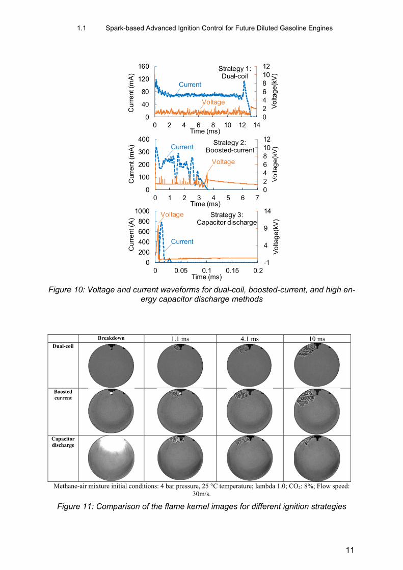
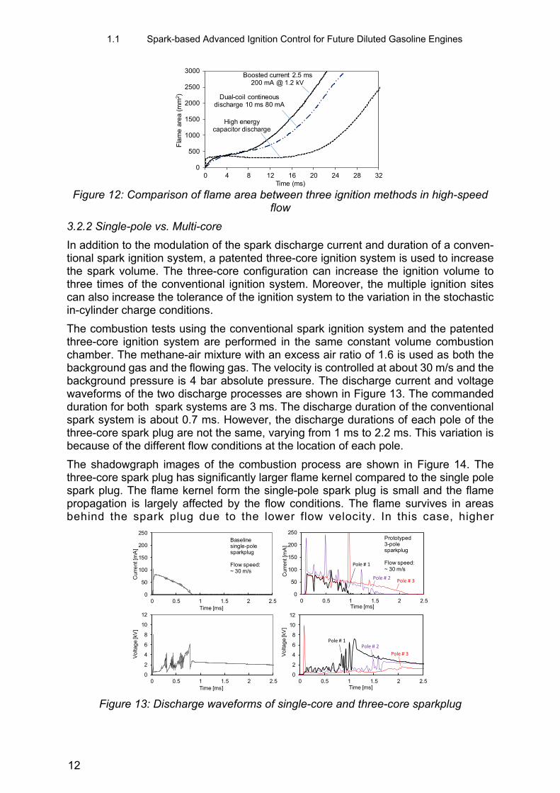
Combustion tests are carried out in the constant volume combustion chamber to in-vestigate the impacts of different spark discharge on the ignition process under flow conditions. Three ignition strategies are used as shown in Figure 10. The three strate-gies include a low current discharge (80 mA) but with a long discharge duration (~13 ms); a boosted current discharge (~200 mA) with a shorter discharge duration (~3 ms); and a capacitor discharge with an extremely high transient current (~800 A) in a very short discharge duration (~15 μs). The background gas in these tests are stoichio-metric methane-air mixture with CO2 dilution of 8% volume ratio. The background pres-sure is 4 bar absolute pressure. The gas flow velocity is controlled at about 30 m/s. The flowing gas is with the same composition as the background gas.
The flame kernel development of the three spark strategies is recorded by the high-speed shadowgraph imaging system and the images are shown in Figure 11. The flame kernel is initiated at the spark gap and keeping attached to the spark plug during the discharge period. The dual coil discharge has the longest discharge duration of about 13 ms, so that an attached flame kernel is observed 10 ms after the break-down. The capacitor discharge is initiated with a very bright spark. The transient high current discharge release high energy in a very short period of time and a “micro explosion” is observed. This high transient energy generates a larger flame kernel compared to the previous two spark discharge strategies, as can be seen from the images recorded at 0.6 ms after breakdown.
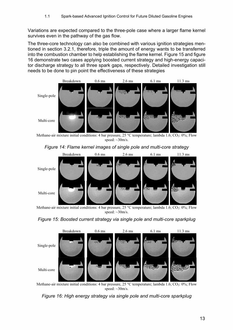
However, due to the very limited duration, this initial advance is not carried to the later phase of flame kernel development. The flame areas of the three tests are shown in Figure 12. The results from these three tests suggest that both the discharge current level and discharge duration are important factors in the flame kernel develop ment under flow conditions. The flame kernel development is impaired when the spark cur-rent is too low or the discharge duration is too short.
0
2
4
6
0 0.2 0.4 0.6 0.8 1 1.2 1.4
Pla
sma
leng
th (
mm
)
Time (ms)
Boosted current @ 1.8 kV Baseline6 bar ~55 m/s
0
2
4
6
0 0.2 0.4 0.6 0.8 1 1.2 1.4
Pla
sma
leng
th (
mm
)
Time (ms)
Boosted current @ 1.8 kV Baseline11 bar ~50 m/s
10
1.1 Spark-based Advanced Ignition Control for Future Diluted Gasoline Engines
Figure 10: Voltage and current waveforms for dual-coil, boosted-current, and high en-ergy capacitor discharge methods
Breakdown 1.1 ms 4.1 ms 10 ms
Dual-coil
Boosted current
Capacitor discharge
Methane-air mixture initial conditions: 4 bar pressure, 25 °C temperature; lambda 1.0; CO2: 8%; Flow speed:
30m/s.
Figure 11: Comparison of the flame kernel images for different ignition strategies
-1
4
9
14
0
200
400
600
800
1000
0 0.05 0.1 0.15 0.2V
olta
ge
(kV
)
Cur
rent
(A
)
Time (ms)
Voltage
Current
Strategy 3:Capacitor discharge
024681012
0
100
200
300
400
0 1 2 3 4 5 6 7
Vo
ltag
e(k
V)
Cur
rent
(m
A)
Time (ms)
Voltage
CurrentStrategy 2:
Boosted-current
024681012
0
40
80
120
160
0 2 4 6 8 10 12 14
Vo
ltag
e(k
V)
Cur
rent
(m
A)
Time (ms)
Voltage
Current
Strategy 1:Dual-coil
11
1.1 Spark-based Advanced Ignition Control for Future Diluted Gasoline Engines
Figure 12: Comparison of flame area between three ignition methods in high-speed
flow
3.2.2 Single-pole vs. Multi-core
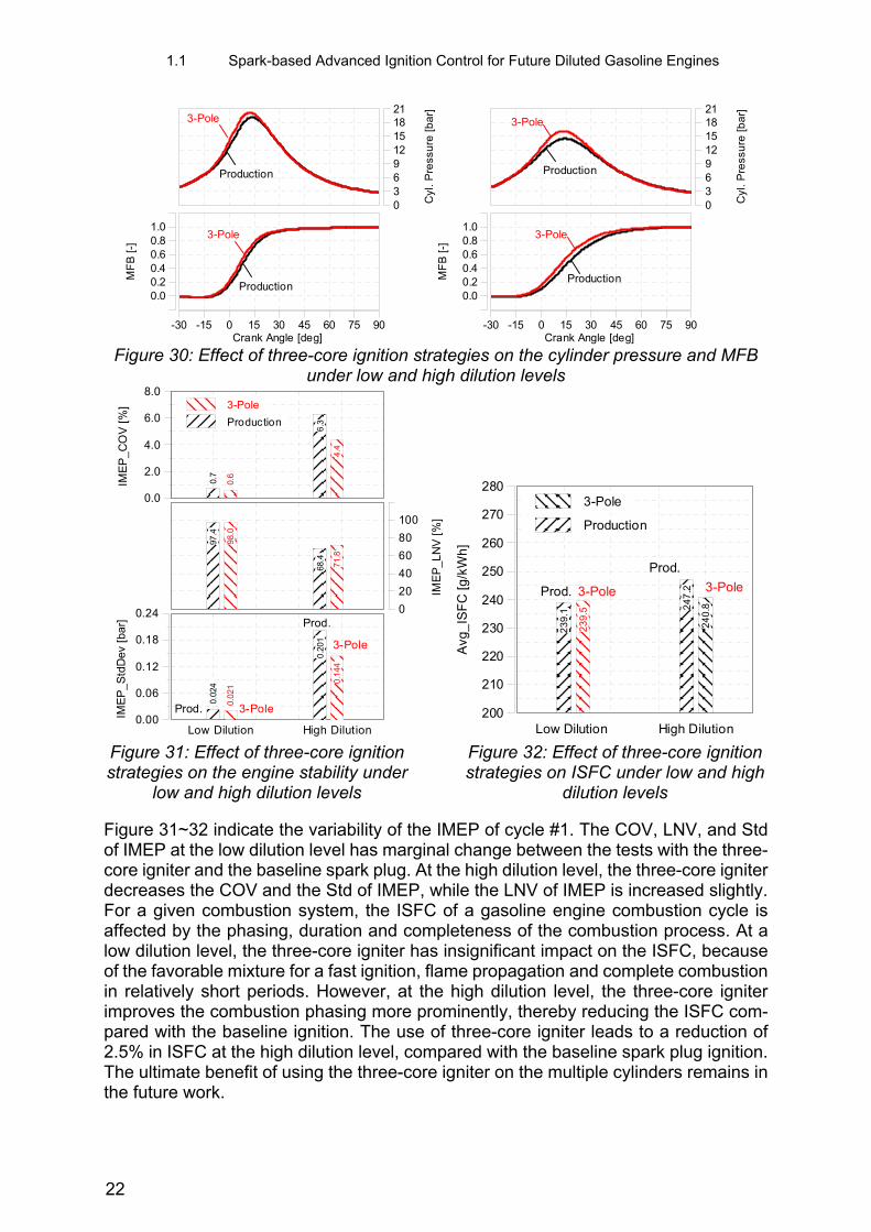
In addition to the modulation of the spark discharge current and duration of a conven-tional spark ignition system, a patented three-core ignition system is used to increase the spark volume. The three-core configuration can increase the ignition volume to three times of the conventional ignition system. Moreover, the multiple ignition sites can also increase the tolerance of the ignition system to the variation in the stochastic in-cylinder charge conditions.
The combustion tests using the conventional spark ignition system and the patented three-core ignition system are performed in the same constant volume combustion chamber. The methane-air mixture with an excess air ratio of 1.6 is used as both the background gas and the flowing gas. The velocity is controlled at about 30 m/s and the background pressure is 4 bar absolute pressure. The discharge current and voltage waveforms of the two discharge processes are shown in Figure 13. The commanded duration for both spark systems are 3 ms. The discharge duration of the conventional spark system is about 0.7 ms. However, the discharge durations of each pole of the three-core spark plug are not the same, varying from 1 ms to 2.2 ms. This variation is because of the different flow conditions at the location of each pole.
The shadowgraph images of the combustion process are shown in Figure 14. The three-core spark plug has significantly larger flame kernel compared to the single pole spark plug. The flame kernel form the single-pole spark plug is small and the flame propagation is largely affected by the flow conditions. The flame survives in areas behind the spark plug due to the lower flow velocity. In this case, higher
Figure 13: Discharge waveforms of single-core and three-core sparkplug
0
500
1000
1500
2000
2500
3000
0 4 8 12 16 20 24 28 32F
lam
e a
rea
(mm
2 )Time (ms)
Boosted current 2.5 ms 200 mA @ 1.2 kV
Dual-coil contineous discharge 10 ms 80 mA
High energycapacitor discharge
0
50
100
150
200
250
0 0.5 1 1.5 2 2.5
Cur
rent
[mA
]
Time [ms]
Baselinesingle-pole sparkplug
Flow speed:~ 30 m/s
0
2
4
6
8
10
12
0 0.5 1 1.5 2 2.5
Vo
ltag
e [k
V]
Time [ms]
0
50
100
150
200
250
0 0.5 1 1.5 2 2.5
Cur
rent
[mA
]
Time [ms]
Prototyped 3-pole sparkplug
Flow speed:~ 30 m/s
Pole # 1
Pole # 2Pole # 3
0
2
4
6
8
10
12
0 0.5 1 1.5 2 2.5
Vo
ltag
e [k
V]
Time [ms]
Pole # 1Pole # 2
Pole # 3
12
1.1 Spark-based Advanced Ignition Control for Future Diluted Gasoline Engines
Variations are expected compared to the three-pole case where a larger flame kernel survives even in the pathway of the gas flow.
The three-core technology can also be combined with various ignition strategies men-tioned in section 3.2.1, therefore, triple the amount of energy wants to be transferred into the combustion chamber to help establishing the flame kernel. Figure 15 and figure 16 demonstrate two cases applying boosted current strategy and high-energy capaci-tor discharge strategy to all three spark gaps, respectively. Detailed investigation still needs to be done to pin point the effectiveness of these strategies
Breakdown 0.6 ms 2.6 ms 6.1 ms 11.3 ms
Single-pole
Multi-core
Methane-air mixture initial conditions: 4 bar pressure, 25 °C temperature; lambda 1.6; CO2: 0%; Flow
speed: ~30m/s.
Figure 14: Flame kernel images of single pole and multi-core strategy
Breakdown 0.6 ms 2.6 ms 6.1 ms 11.3 ms
Single-pole
Multi-core
Methane-air mixture initial conditions: 4 bar pressure, 25 °C temperature; lambda 1.6; CO2: 0%; Flow
speed: ~30m/s.
Figure 15: Boosted current strategy via single pole and multi-core sparkplug
Breakdown 0.6 ms 2.6 ms 6.1 ms 11.3 ms
Single-pole
Multi-core
Methane-air mixture initial conditions: 4 bar pressure, 25 °C temperature; lambda 1.6; CO2: 0%; Flow
speed: ~30m/s.
Figure 16: High energy strategy via single pole and multi-core sparkplug
13

1.1 Spark-based Advanced Ignition Control for Future Diluted Gasoline Engines
under different energy level as well as background conditions (cross flow speed, pres-sure, temperature), but the figures shows a clear advantage when energy delivery amount is tripled. When in-cylinder air movement is intense, the size of the initial flame kernel is essential for flame to propagate. The three flame kernels generated by the three independent spark gaps can merge with each other and form a flame kernel in larger, therefore, shorten the transition period from initial flame kernel to a self-sus-tained flame kernel.
3.3 Effect of advanced ignition strategies on lean/diluted gasoline combustion – evaluation on single-cylinder research engine
3.3.1 Effect of boosted current on lean-burn engine control
The boosted current ignition device can generate a strong spark channel with a current level up to 500 mA and an extended glow duration up to 10 ms. The current boosting command is triggered by the falling edge of the ignition coil charging control signal. The current level is adjusted by the regulation of the voltage applied onto the spark gap after the breakdown. To understand the effect of the current level on the lean burn operation, tests were conducted with different sparking current profiles. The parameter settings of different ignition strategies are given in table 4. The engine was operated at lambda 1.4. Five different ignition strategies were tested. The strategy 1 and strategy 2 utilize conventional ignition energy control methods. The rest ones are boosted cur-rent ignition strategies with the current level changing from 200 mA to 500 mA. The current waveforms of the five different ignition strategies are given in figure 17.
Spark timing sweep tests are conducted for all five ignition strategies under same en-gine operating conditions. The engine IMEP, COV of IMEP, and the misfire rates during the spark timing sweep tests are shown in figure 18. It is observed that the boosted current is able to obtain higher IMEP and lower cycle to cycle variation. The 500 mA boosted current case has stronger ability to stabilize the combustion process consist-ently compared with the 200 mA case. It is obvious that the impacts of boosted current on the combustion phasing is more significant when the spark timing is between 305 °CA ~315 °CA. The ignition delay and the CA50 under different spark timing are shown in figure 19. The boosted current ignition strategy can reduce the ignition delay and improve the controllability over the CA50.
Table 4. Test conditions for baseline and boosted current ignition strategies
Peak current (mA)
Charging duration (ms)
Current boost Spark plug
Strategy 1 30 mA 2 NA Stock Iridium Strategy 2 100 mA 5 NA Stock Iridium Strategy 3 200 mA 2 2 ms @ 200 mA Stock Iridium Strategy 4 500 mA 2 2 ms @ 500 mA Stock Iridium Strategy 5 500 mA 5 2 ms @ 500 mA Stock Iridium
14

1.1 Spark-based Advanced Ignition Control for Future Diluted Gasoline Engines
Figure 17. Current waveforms for various ignition strategies
Figure 18: Effect of boosted current ignition strategies on lean burn stability (CR 9.2, λ= 1.4)
Figure 19: Effect of boosted current ignition strategies on ignition delay and CA50 (CR 9.2, λ= 1.4)
3.3.2 Effect of multi-core on lean-burn control
Previous investigations indicate that the three-core ignition can improve the lean-burn gasoline combustion thus achieve fuel efficiency gain because of the extension of lean limits. The three-core ignition can improve the combustion phasing control for the low load ultra-lean operation. The results were collected at the compression ratio of 13:1. Because of the high compression ratio, the engine load was limited up to 6 bar IMEP because of the severe knocking. The newer results were collected from the single-cylinder engine with a lowered compression ratio of 9.2:1. The engine load was extended to 10 bar IMEP. Test results of the spark timing sweep with lambda 1.5 and 1.66 are given in figure 20. At lambda 1.5, the three-core behaves very similar to the single-pole baseline ignition, while the difference was much bigger at lambda 1.66.
0
100
200
300
400
500
600
700
-0.5 0 0.5 1 1.5 2 2.5C
urre
nt [
mA
]Time [ms]
Strategy 1 30 mAStrategy 2 100 mAStrategy 3 200 mAStrategy 4 500 mAStrategy 5 500 mA
1
1.5
2
2.5
3
3.5
4
30 40 50 60 70
IME
P [
bar]
SOI [°CA BTDC]
Strategy 1 30 mA
Strategy 2 100 mA
Strategy 3 200 mA
Strategy 4 500 mA
Strategy 5 500 mA
0
10
20
30
40
50
60
70
80
90
100
30 40 50 60 70
Cov
IME
P [%
]
SOI [°CA BTDC]
Strategy 1 30 mAStrategy 2 100 mAStrategy 3 200 mAStrategy 4 500 mAStrategy 5 500 mA
0
5
10
15
20
25
30
30 40 50 60 70
Mis
fire
rate
[%]
SOI [°CA BTDC]
Strategy 1 30 mAStrategy 2 100 mAStrategy 3 200 mAStrategy 4 500 mAStrategy 5 500 mA
30
35
40
45
50
30 40 50 60 70
ID [°
CA
]
SOI [°CA BTDC]
Strategy 1 30 mAStrategy 2 100 mAStrategy 3 200 mAStrategy 4 500 mAStrategy 5 500 mA
5
10
15
20
25
30
35
30 40 50 60 70
CA
50
[°C
AA
TD
C]
SOI [°CA BTDC]
Strategy 1 30 mA
Strategy 2 100 mA
Strategy 3 200 mA
Strategy 4 500 mA
Strategy 5 500 mA
15

1.1 Spark-based Advanced Ignition Control for Future Diluted Gasoline Engines
With the spark timing advanced, the baseline single-pole ignition cannot maintian the target IMEP. Severe cyclic variations are also observed. Cylinder pressure and heat release rate curves of example cases at spark timing of -40 °CA ATDC are shown in figure 21. The three-core ignition can noticeably advance the heat release rate thereby leading to higher cylinder pressure, for both lambda 1.5 and 1.66 cases.
Figure 20: Effect of three-core ignition strategies on lean burn engine stability
Figure 21: Effect of three-core ignition strategies on cylinder pressure and heat re-lease rate
The combustion and emissions parameters for lean burn operation are given in figure 22, comparing the effects of three-core ignition and single-pole baseline ignition strat-egies. The three-core ignition exhibits better controllability over the CA50 for both lambda 1.5 and 1.66 cases. The standard deviation of CA50 is also improved by the three-core ignition. When the spark timing is advanced under the lean burn condition,
5
6
7
8
9
10
11
12
-55 -50 -45 -40 -35 -30 -25 -20 -15 -10
IME
P (b
ar)
3 Pole 3 PoleBaseline Baseline
λ 1.66 1-pole
λ 1.66 3-pole
λ 1.5 1-pole
λ 1.5 3-pole
0
4
8
12
16
20
-55 -50 -45 -40 -35 -30 -25 -20 -15 -10
Co
v IM
EP
(%)
λ 1.66 1-pole
λ 1.66 3-pole
λ 1.5 1-pole
λ 1.5 3-pole
Spark timing (°CA ATDC)
Spark timing (°CA ATDC)
-10
20
50
80
110
140
170
200
230
0
10
20
30
40
50
60
-60 -40 -20 0 20 40 60 80
HR
R (J
/°C
A)C
ylin
der
pres
sure
(bar
)
Crank angle (°CA ATDC)
Baseline3 pole
-10
20
50
80
110
140
170
200
230
0
10
20
30
40
50
60
-60 -40 -20 0 20 40 60 80
HR
R (J
/°C
A)Cyl
inde
r pr
essu
re (b
ar)
Crank angle (°CA ATDC)
Baseline3 pole
Target IMEP: 10 bar; λ =1.5; Spark timing: -40 °CA ATDCP_int. : 2.2 bar; 1300 rpm; CR: 9.2 :1
Target IMEP: 10 bar; λ =1.66;Spark timing: -40 °CA ATDCP_int. : 2.2 bar; 1300 rpm; CR: 9.2 :1
16

1.1 Spark-based Advanced Ignition Control for Future Diluted Gasoline Engines
the engine is achieving maximum IMEP without knocking. Therefore, an increasing trend of the indicated thermal efficiency is observed, except for the baseline ignition at lambda 1.66. The three-core ignition leads to a higher level of NOx emissions that means a stronger combustion, compared with the baseline single-pole ignition strat-egy. The HC and CO emissions are reduced by the three-core ignition, which suggests improved combustion efficiency of the lean-burn operation.
Figure 22: Effect of three-core ignition strategies on combustion and emissions of
lean burn
3.3.3 Comparison between multi-core and multi-coil single-pole ignition strategies
The three-core igniter uses three independent ignition coils for ignition energy distribu-tion control. The output of the three ignition coils can also be bundled together to deliver the ignition energy to single spark gap. Bundling the output of the three coils can sig-nificantly enhance the spark current of the single-pole iridium spark plug. Three spark discharge cases are compared in figure 23. Case 1 uses the three-core igniter with each pole energized by one of the three independent ignition coils. The peak spark current in case 1 is about 50 mA. Case 2 uses the reference iridium spark plug con-necting to one of the ignition coils. A peak current of about 110mA is achieved for case 2. Case 3 discharge three coils simultaneously onto the single-pole iridium spark plug, producing a peak spark current of about 280 mA. The charging duration for case 2 and case 3 are kept the same, meaning that the stored energy in the primary winding of the ignition coils for case 3 should be about 3 times of that for case 2. Case 1 uses a charging duration shorter than those for case 2 and case 3.
5
10
15
20
25
30
35
-55 -50 -45 -40 -35 -30 -25 -20 -15 -10
CA
50
( °C
A A
TD
C)
λ 1.66 1-pole
λ 1.66 3-pole
λ 1.5 1-pole
λ 1.5 3-pole
0
4
8
12
-55 -50 -45 -40 -35 -30 -25 -20 -15 -10
ST
D C
A5
0 (°
CA
)
λ 1.66 1-pole
λ 1.66 3-pole
λ 1.5 1-pole
λ 1.5 3-pole
20
25
30
35
40
45
-55 -50 -45 -40 -35 -30 -25 -20 -15 -10
Ind
. Eff
. (%
)
λ 1.66 1-pole
λ 1.66 3-pole
λ 1.5 1-pole
λ 1.5 3-pole
Spark timing (°CA ATDC)
Spark timing (°CA ATDC)
Spark timing (°CA ATDC)
CA50
STDCA50
Efficiency
0
500
1000
1500
2000
-55 -50 -45 -40 -35 -30 -25 -20 -15 -10
NO
X (
pp
m)
λ 1.66 1-pole
λ 1.66 3-pole
λ 1.5 1-pole
λ 1.5 3-pole
0
1000
2000
3000
4000
5000
6000
7000
-55 -50 -45 -40 -35 -30 -25 -20 -15 -10
HC
(p
pm
)λ 1.66 1-pole
λ 1.66 3-pole
λ 1.5 1-pole λ 1.5
3-pole
0
1000
2000
3000
-55 -50 -45 -40 -35 -30 -25 -20 -15 -10
CO
(pp
m)
λ 1.66 1-pole
λ 1.66 3-pole
λ 1.5 1-pole
λ 1.5 3-pole
Spark timing (°CA ATDC)
Spark timing (°CA ATDC)
Spark timing (°CA ATDC)
NOx
HC
CO
17

1.1 Spark-based Advanced Ignition Control for Future Diluted Gasoline Engines
Figure 23: Spark current waveforms for three-core and 3-coil ignition strategies
Figure 24: Effect of three-core strategy on lean burn engine stability
Figure 25: Effect of three-core strategy on cylinder pressure and heat release rate
0
50
100
150
200
250
300
0 1 2 3 4 5 6
Sp
ark
curr
ent
(mA
)Time (ms)
Case 2: 1-coil + single-pole
Case 1: 3-coil + 3-pole
Case 3: 3-coil + single-pole
2.50
2.70
2.90
3.10
3.30
3.50
290 310 330 350
IME
P (B
ar)
Ignition Timing (°CA)
λ=1.0 1 Coil
3 Coil
three pole
2.50
2.70
2.90
3.10
3.30
3.50
290 310 330 350
IME
P (B
ar)
Ignition Timing (°CA)
λ=1.4
1 Coil3 Coilthee pole
2.50
2.70
2.90
3.10
3.30
3.50
290 310 330 350
IME
P (B
ar)
Ignition Timing (°CA)
λ=1.7 1 Coil
3 Coil
Three pole
0
1
2
3
4
5
290 310 330 350C
OV
IME
P (%
)
Ignition Timing (°CA)
λ=1.0
1 Coil3 CoilThree pole
0
2
4
6
8
10
290 310 330 350
CO
V IM
EP
(%)
Ignition Timing (°CA)
λ=1.4 1 Coil3 CoilThree pole
0
5
10
15
20
25
30
290 310 330 350
CO
V IM
EP
(%)
Ignition Timing (°CA)
λ=1.7 1 Coil
3 Coil
Three pole
-5
0
5
10
15
20
25
30
35
40
45
50
-10
-5
0
5
10
15
20
25
30
-60 -40 -20 0 20 40 60 80
HR
R (J
/°C
A)Cyl
inde
r pr
essu
re (
bar)
Crank angle (°CA ATDC)
λ: 1.0 Baseline3-coil3-pole
Spark timing:-17 °CA ATDC
-5
0
5
10
15
20
25
30
35
40
45
50
-10
-5
0
5
10
15
20
25
30
-60 -40 -20 0 20 40 60 80
HR
R (J
/°C
A)Cyl
inde
r pr
essu
re (
bar)
Crank angle (°CA ATDC)
λ: 1.4Baseline3-coil3-pole
Spark timing: -26 °CA ATDC
-5
0
5
10
15
20
25
30
35
40
45
50
-10
-5
0
5
10
15
20
25
30
35
40
-60 -40 -20 0 20 40 60 80
HR
R (J
/°C
A)Cyl
inde
r pr
essu
re (
bar)
Crank angle (°CA ATDC)
λ: 1.7Baseline3-coil3-pole
Spark timing: -58 °CA ATDC
18

1.1 Spark-based Advanced Ignition Control for Future Diluted Gasoline Engines
Experiments are conducted to evaluate the three ignition strategies given in figure 23 for lambda of 1.0, 1.4, and 1.7. The engine IMEP and the COV of IMEP against the spark timing are plotted in figure 24. For engine operations with near stoichiometric and moderate lean mixtures, the ignition behaviors are very similar for different ignition strategies. For the very lean mixture with λ of about 1.7, the three-core ignition energy distribution strategy exhibits lower COV of IMEP, shorter ignition delay and less varying CA50. The cylinder pressure and heat release rate for the three ignition strategies at different lambda are given in figure 25. The enhancement of spark current by bundling the outputs of three coils does improve the ignition for the single-pole sparkplug, whereas the benefits are less prominent than that of using three-core igniter with a lower peak current for each spark.
3.3.4 Comparison between multi-core and boosted current single-pole strategies
Three ignition strategies are compared at 10 bar IMEP with lambda 1.5 and 1.66. The parameter settings of three ignition strategies are given in table 5. The purpose of this test is to compare the effect of the boosted current single-pole strategy with the three-core ignition strategy for lean-burn combustion control. The baseline ignition strategy generates a spark with a peak current of 100 mA. The boosted current strat-egy supplies a 2 ms pulse with 500 mA over the baseline spark. For the three-core ignition strategy, each of the poles has a discharge current level the same as that of the baseline ignition strategy. Spark timing sweep experiments are performed for each ignition strategy at lambda 1.5 and 1.66 respectively. The engine load target is 10 bar IMEP.
The combustion parameters are compared in figure 26 for the different ignition strate-gies. During the spark timing sweep, the three-core performs the best among the three ignition strategies, in terms of the combustion phasing control sensitivity and the en-gine stability. The boosted current strategy can also improve the lean-burn combustion control, but the effect is less prominent compared with the three-core ignition strategy under the selected test conditions. The cylinder pressure and the heat release rate curves are compared in figure 27. The spark timing is set at -40 °CA ATDC for the three cases and the lambda was 1.66. For the same spark timing, the three-core igni-tion generates the earliest heat release and the highest cylinder pressure. On the scat-tering plot of IMEP vs CA50 (figure 28), the three-core ignition exhibits the earliest CA50 and the least scattering of both IMEP and CA50, compared to the boosted-cur-rent and the baseline ignition strategies.
Table 5: Test conditions for baseline, boosted current and three-core comparison
Peak current (mA)
Charging duration (ms)
Current boost Energy to sparkplug (mJ)
Spark plug
Baseline 100 mA 5 NA 150 mJ Stock Iridium Boosted current 500 mA 5 2 ms @ 500 mA ~2 J Stock Iridium three-core 100 mA 5 NA 450 mJ Three-core
19

1.1 Spark-based Advanced Ignition Control for Future Diluted Gasoline Engines
Figure 26: Combustion parameters for the various ignition strategies
Figure 27: Cylinder pressure and HRR for various ignition strategies
Figure 28: IMEP scattering plots for various ignition strategies
0
2
4
6
8
10
-40 -30 -20 -10 0
CO
V_
IME
P (
%)
Spark timing (° CA ATDC)
3 PoleBoosted currentBaseline
0
10
20
30
40
-40 -30 -20 -10 0
CA
50
(°C
A A
TD
C)
Spark timing (° CA ATDC)
3 PoleBoosted currentBaseline
05
10152025303540
-60 -50 -40 -30 -20
CO
V_
IME
P (
%)
Spark timing (° CA ATDC)
3 PoleBoosted currentBaseline
0
10
20
30
40
-60 -50 -40 -30 -20
CA
50
(°C
A A
TD
C)
Spark timing (° CA ATDC)
3 PoleBoosted currentBaseline
Target IMEP: 10 bar; λ =1.5; P_int. : 2.0 bar; 1300 rpm; CR: 9.2 :1
Target IMEP: 10 bar; λ =1.66; P_int. : 2.2 bar; 1300 rpm; CR: 9.2 :1
20
30
40
50
-40 -30 -20 -10 0
Ind
. e
ff. (
%)
Spark timing (° CA ATDC)
3 PoleBoosted currentBaseline
20
30
40
50
-60 -50 -40 -30 -20
Ind
. e
ff. (
%)
Spark timing (° CA ATDC)
3 PoleBoosted currentBaseline
-10
10
30
50
70
90
110
130
150
0
10
20
30
40
50
60
-60 -40 -20 0 20 40 60 80
HR
R (
J/°C
A)
Cyl
ind
er
pre
ssur
e (
ba
r)
Crank Angle (°CA ATDC)
BaselineBoosted Current3 pole
Target IMEP: 10 bar; λ =1.66; Spark timing: -40 °CA ATDCP_int. : 2.2 bar; 1300 rpm; CR: 9.2 :1
4
6
8
10
12
14
4 6 8 10 12 14
IME
P c
ylce
#n
(ba
r)
IMEP cycle #n-1 (bar)
BaselineBoosted Current3 pole
4
6
8
10
12
14
0 5 10 15 20 25 30 35 40
IME
P (
ba
r)
CA 50 (°CA ATDC)
BaselineBoosted Current3 pole
Target IMEP: 10 bar; λ =1.66; Spark timing: -40 °CA ATDCP_int. : 2.2 bar; 1300 rpm; CR: 9.2 :1
20

1.1 Spark-based Advanced Ignition Control for Future Diluted Gasoline Engines
3.4 Evaluation of multi-core ignition on multiple-cylinder production engine under high dilution
Comparison tests have been conducted on a production gasoline engine for the three-core igniter and the original single-pole spark plug. The comparison comprises a base-line test with the production ignition system and a repeat test with a three-core igniter installed in cylinder 1 under the same test conditions. In both tests, the engine runs at 1500 rpm and 2.62 bar BMEP, the Ford World Wide Mapping Point (WWMP); cam timing retard is employed to increase the trapped exhaust gas and thus to achieve higher internal EGR dilution. The retarded cam timing and diluted combustion can im-prove the engine fuel economy at the tested engine speed/load conditions. As the di-lution gradually increases, an overall trend of reduced BSFC is observed with the great-est improvement reaching ~5%. However, the BSFC trended to decrease at the high-est dilution level when the cam retard is set to 50 degrees. The primary cause is the late combustion phasing and incomplete combustion. A large portion of the fuel con-sumption improvement comes from the reduction of pumping loss. At a constant en-gine load of 2.62 bar BMEP, the engine MAP increases; therefore, the reduced vac-uum in the intake manifold ultimately results in less pumping work. Since the engine runs at a better brake efficiency, it requires less air and fuel to achieve 2.62 bar BMEP. As the cam phasing retarded, the ISFC remains nearly unchanged until the cam retard approaches 45 and 50 degrees. Combustion phasing and combustion duration of three-core and the baseline ignition strategies are compared in figure 29. As can be seen, the 3-core ignition can shorten the combustion duration and move forward the combustion phasing, with the same spark timing of the baseline single-pole ignition. In figure 30, comparisons of the cylinder pressure and the mass fraction burnt are made between three-core igniter and the baseline spark plug, for the low and high dilution cases respectively. In both cases, three-core igniter leads to an earlier start of com-bustion and a faster burn rate. The three-core igniter results in a higher peak cylinder pressure compared with the baseline spark plug with the same spark timing. The dif-ference is more noticeable for the high dilution level associated with the large VCT retard angle.
Figure 29: Effect of three-core ignition strategies on burning duration and combustion
phasing
0 5 10 15 20 25 30 35 40 45 50VCT Retard [deg.]
Sp
ark
Ad
van
ce [
de
g.]
30
35
40
45
50
55
CA
50
[d
eg
.atd
c]
0
4
8
12
16
20Bu
rn1
09
0 D
ura
. [d
eg
.]
20
25
30
35
40
45
0 5 10 15 20 25 30 35 40 45 50VCT Retard [deg.]
3-Pole
Production
3-Pole
Production
21
1.1 Spark-based Advanced Ignition Control for Future Diluted Gasoline Engines
Figure 30: Effect of three-core ignition strategies on the cylinder pressure and MFB
under low and high dilution levels
Figure 31: Effect of three-core ignition strategies on the engine stability under
low and high dilution levels
Figure 32: Effect of three-core ignition strategies on ISFC under low and high
dilution levels
Figure 31~32 indicate the variability of the IMEP of cycle #1. The COV, LNV, and Std of IMEP at the low dilution level has marginal change between the tests with the three-core igniter and the baseline spark plug. At the high dilution level, the three-core igniter decreases the COV and the Std of IMEP, while the LNV of IMEP is increased slightly. For a given combustion system, the ISFC of a gasoline engine combustion cycle is affected by the phasing, duration and completeness of the combustion process. At a low dilution level, the three-core igniter has insignificant impact on the ISFC, because of the favorable mixture for a fast ignition, flame propagation and complete combustion in relatively short periods. However, at the high dilution level, the three-core igniter improves the combustion phasing more prominently, thereby reducing the ISFC com-pared with the baseline ignition. The use of three-core igniter leads to a reduction of 2.5% in ISFC at the high dilution level, compared with the baseline spark plug ignition. The ultimate benefit of using the three-core igniter on the multiple cylinders remains in the future work.
-30 -15 0 15 30 45 60 75 90Crank Angle [deg]
MF
B [
-]
0.00.20.40.60.81.0
Cyl
. P
ress
ure
[b
ar]
036912151821
3-Pole
Production
3-Pole
Production
-30 -15 0 15 30 45 60 75 90Crank Angle [deg]
MF
B [
-]
0.00.20.40.60.81.0
Cyl
. P
ress
ure
[b
ar]
036912151821
3-Pole
Production
3-Pole
Production
IME
P_S
tdD
ev [
bar]
0.00
0.06
0.12
0.18
0.24
0.02
4
Low Dilution High Dilution
0.02
1
0.20
1
0.14
4
Prod.
3-Pole
3-PoleProd.
IME
P_L
NV
[%
]
0
20
40
60
80
100
97.4
98.0
68.4
71.8
IME
P_C
OV
[%
]
0.0
2.0
4.0
6.0
8.0
0.7
0.6
6.3Production
4.4
3-Pole
23
9.1
23
9.5 2
47
.2
Production
Avg
_IS
FC
[g
/kW
h]
200
210
220
230
240
250
260
270
280
24
0.8
3-Pole
Low Dilution High Dilution
Prod.
3-PoleProd. 3-Pole
22

1.1 Spark-based Advanced Ignition Control for Future Diluted Gasoline Engines
Conclusions
Ignition technologies with enhanced ignition capability including discharge energy pro-filing as well as multi-core ignition system are introduced in this paper, and their effects on ignition improvements are investigated on both constant volume combustion ves-sels and research engines. Conclusions can be drawn as below. (1) Under flow condition, boosted discharge current can significantly increase the length of the plasma channel, and reduce the frequency of the blow-off event. (2) A longer glow phase, boosted discharge current, and transient high ignition en-ergy can all enhance the ignition ability of the plasma channel; the boosted discharge current strategy appears to be most effective under CO2 diluted conditions through test on the constant volume combustion chamber. (3) Engine test results show that the ignition technologies are most effective when intake charge is at the boundary of lean/dilution limit; single cylinder engine test under 10 bar IMEP shows a indicated thermal efficiency improvement of 6% when engine is running under 1.66 using three-core ignition system; while ISFC is improved by 5% on a Ford multi-cylinder engine at 2.6 bar IMEP, 1500 rpm when using a multi-core ignition system under high EGR dilution condition.
4 Acknowledgements
The research at the Clean Combustion Engine Laboratory is sponsored by the NSERC Industrial Research Chair program, NSERC Collaborative Research and development Program, Ontario Center of Excellency – VIP II program, Ford Motor Company of Can-ada Ltd., and the University of Windsor.
5 References
1. Wei, H., Zhu, T., Shu, G., Tan, L., et al. “Gasoline Engine Exhaust Gas Recirculation– A Review,” Applied Energy. 99:534–44, 2012, doi:10.1016/ j.apenergy. 2012.05.011.
2. Gallon, E., Fontana, G., Palmaccio, R., “Effects of Exhaust Gas Recycle in a Down-sized Gasoline Engine,” Applied Energy. 105:99–107, 2013, doi: 10.1016/j.apen-ergy.2012.12.046.
3. Takahashi, D., Nakata, K., Yoshihara, Y., Ohta, Y. et al., “Combustion Development to Achieve Engine Thermal Efficiency of 40% for Hybrid Vehicles,” SAE Technical Paper 2015-01-1254, 2015, doi: 10.4271/2015-01-1254.
4. Zheng, M., Tan, Y., Mulenga, M., and Wang, M., “Thermal Efficiency Analyses of Diesel Low Temperature Combustion Cycles,” SAE Technical Paper 2007-01-4019, 2007, doi:10.4271/2007-01-4019.
5. Gukelberger, R., Alger, T., Gingrich, J., and Mangold, B., "Impact of Operating Pa-rameters on Ignition System Energy Consumption," SAE Technical Paper 2014-01-1233, 2014, doi:10.4271/2014-01-1233.
6. Hampe, C., Kubach, H., Spicher, U., et al. “Investigations of Ignition Processes Using High Frequency Ignition,” SAE Tech Paper, 2013-01-1633, 2013; doi: 10.4271/2013-01-1633.
7. Shiraishi, T., Urushihara, T., Gundersen, M., “A Trial of Ignition Innovation of Gasoline Engine by Nanosecond Pulsed Low Temperature Plasma Ignition,” Journal of Phys-ics D: Applied Physics, 2009, 42: 135208; doi: 10.1088/00223727/42/13/135208.
8. Sjöberg, M., Zeng, W., Singleton, D., Sanders, J., et al. “Combined Effects of Multi-pulse Transient Plasma Ignition and Intake Heating on Lean Limits of Well-mixed E85
23
1.1 Spark-based Advanced Ignition Control for Future Diluted Gasoline Engines
DISI Engine Operation,” SAE Int J Engines, 2014, 7(4):1781-1801; doi: 10.4271/2014-01-2615.
9. Rohwein, G. J., “An Efficient Power-Enhanced Ignition System,” IEEE Transactions on Plasma Science, 25(2): 306-310, 1997, doi:10.1109/27.602504.
10. Rohwein, G. and Camilli, L., “Automotive Ignition Transfer Efficiency,” SAE Technical Paper 2002-01-2839, 2002, doi:10.4271/2002-01-2839.
11. Yoshida, K., Shoji, H., and Tanaka, H., “Performance of Newly Developed Plasma Jet Igniter,” SAE Technical Paper 1999-01-3327, 1999, doi:10.4271/1999-01-3327.
12. Dale, J.D., Checkel, M.D., Smy, P.R., “Application of High Energy Ignition Systems to Engines,” Progress in Energy and Combustion Science, 23(5-6): 379-398, 1997, doi:10.1016/S0360-1285(97)00011-7.
13. Heise, V., Farah, P., Husted, H., and Wolf, E., “High Frequency Ignition System for Gasoline Direct Injection Engines,” SAE Technical Paper 2011-01-1223, 2011, doi:10.4271/2011-01-1223.
14. Alger, T., Gingrich, J., Mangold, B., and Roberts, C., “A Continuous Discharge Igni-tion System for EGR Limit Extension in SI Engines,” SAE Int. J. Engines 4(1):677-692, 2011, doi:10.4271/2011-01-0661.
15. Hall, M., Matthews, R., and Ezekoye, O., “Railplug Ignition Operating Characteristics and Performance: A Review,” SAE Technical Paper 2007-01-1832, 2007, doi:10.4271/2007-01-1832.
16. Suess, M, Guenthner, M, Schenk, M, et al., “Investigation of the Potential of Corona Ignition to Control Gasoline Homogeneous Charge Compression Ignition Combus-tion,” P I MECH ENG D-J AUT, 2011, 226(2): 275-286, doi: 10.1177/0954407011416905.
17. Stevens, C. A., Pertl, F. A., Hoke, J. L., et al. “Comparative Testing of a Novel Micro-wave Ignition Source, the Quarter Wave Coaxial Cavity Igniter,” J Phys D: Appl Phys, 2011, 225(12): 1633-1640, doi: 10.1177/0954407011411389.
18. Ryu, S. K., Won, S.H., Chung, S. H., “Laser-Induced Multi-point Ignition with Single-Shot Laser Using Conical Cavities and Prechamber with Jet Holes,” Proc Combus-tion Inst, 2009, 32(2): 3189–3196, doi:10.1016/j.proci.2008.05.080.
19. US Patent 9.441.604, “Multi-coil Spark Ignition System”, M Zheng, S Yu, K Xie. 20. Xie, K., Yu, S., Zheng, M., “Investigation of Multi-pole Spark Ignition on Flame Kernel
Development and in Engine Operation,” Proceedings of the ASME 2016 Internal Combustion Fall Technical Conference, Oct 9-12, 2016, Greenville, SC, USA, ICEF2016-9474
21. Yu, S., Xie, K., Tan, Q., Wang, M. et al., "Ignition Improvement of Premixed Methane-Air Mixtures by Distributed Spark Discharge," SAE Technical Paper 2015-01-1889, 2015, doi:10.4271/2015-01-1889.
22. Yu, S., Wang, M., and Zheng, M., "Distributed Electrical Discharge to Improve the Ignition of Premixed Quiescent and Turbulent Mixtures," SAE Technical Paper 2016-01-0706, 2016, doi:10.4271/2016-01-0706.
23. Yu, X., Yang, Z., Yu, S., et al., “Boosted Current Spark Strategy for Lean Burn Spark Ignition Engines,” SAE Technical Paper 2018-01-1133, 2018.
24. US Patent Application 15/162,473, “High Power Breakdown Spark Plug”, Inventors: M Zheng, S Yu, L Li, M Liu.
25. Yu, S., Xie, K., Yu, X., et al. The Effect of High-Power Capacitive Spark Discharge on the Ignition and Flame Propagation in a Lean and Diluted Cylinder Charge," SAE Technical Paper 2016-01-0707, 2016.
26. US Patent 9.484.719, “Active Control Resonant Ignition System”, Inventors: M Zheng, S Yu, M Wang.
24
1.1 Spark-based Advanced Ignition Control for Future Diluted Gasoline Engines
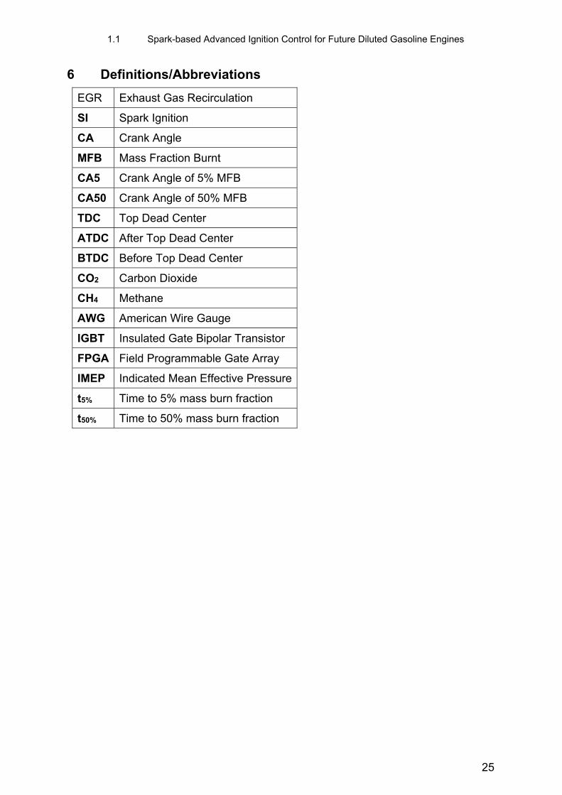
6 Definitions/Abbreviations
EGR Exhaust Gas Recirculation
SI Spark Ignition
CA Crank Angle
MFB Mass Fraction Burnt
CA5 Crank Angle of 5% MFB
CA50 Crank Angle of 50% MFB
TDC Top Dead Center
ATDC After Top Dead Center
BTDC Before Top Dead Center
CO2 Carbon Dioxide
CH4 Methane
AWG American Wire Gauge
IGBT Insulated Gate Bipolar Transistor
FPGA Field Programmable Gate Array
IMEP Indicated Mean Effective Pressure
t5% Time to 5% mass burn fraction
t50% Time to 50% mass burn fraction
25