1 min presentation -...
TRANSCRIPT

1 Min Presentation1. What is your project?
2. What are your main goals?
ENGR 202: INTRO TO ENGINEERING DESIGN 1

Work and Simple MachinesENGR 202: INTRODUCTION TO ENGINEERING DESIGN COURSE
UW COLLEGE OF ENGINEERING
ENGR 202: INTRO TO ENGINEERING DESIGN
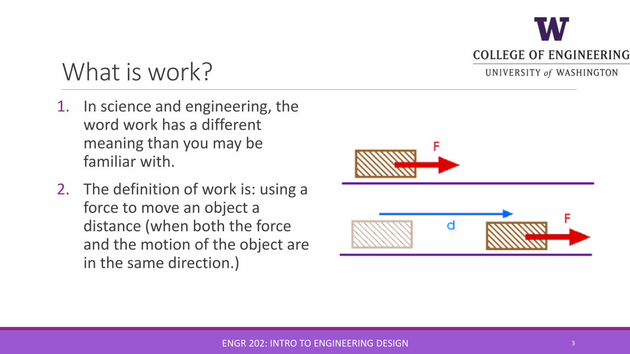
What is work?1. In science and engineering, the
word work has a different meaning than you may be familiar with.
2. The definition of work is: using a force to move an object a distance (when both the force and the motion of the object are in the same direction.)
ENGR 202: INTRO TO ENGINEERING DESIGN 3

What is work and what is not? 1. A mouse pushing a block of cheese
with its nose.
2. Lifting 350 lbs above your head.
3. Carrying a baby from room to room.
4. A teacher applies a force to a wall and becomes exhausted.
5. A book falls off a table and free falls to the ground.
6. A waiter carries a tray full of meals above his head by one arm straight across the room at constant speed.
7. A rocket accelerates through space.
ENGR 202: INTRO TO ENGINEERING DESIGN 4
Y
Y
Y
Y
N
N
N

W = F x DCalculate: If a man pushes a concrete block 10 meters with a force of 20 N, how much work has he done?
ENGR 202: INTRO TO ENGINEERING DESIGN 5
Answer: 200 joules ( W = 20 N x 10m)
Simple Machines
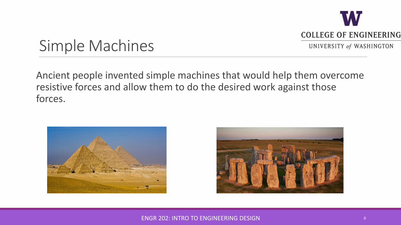
Ancient people invented simple machines that would help them overcome resistive forces and allow them to do the desired work against those forces.
ENGR 202: INTRO TO ENGINEERING DESIGN 6

Simple Machines The six simple machines are:
1. Lever
2. Wheel and Axle (Gears)
3. Pully
4. Inclined Plane
5. Wedge
6. Screw
ENGR 202: INTRO TO ENGINEERING DESIGN 7

Simple Machines A machine is a device that helps make work easier to perform by accomplishing one or more of the following functions:
◦ Transferring a force from one place to another
◦ Changing the direction of a force◦ Increasing the magnitude of a
force◦ Increasing the distance or speed
of a force
ENGR 202: INTRO TO ENGINEERING DESIGN 8

Mechanical Advantage1. It is useful to think about a
machine in terms of the input force (the force you apply) and the output force (force which is applied to the task).
2. When a machine takes a small input force and increases the magnitude of the output force, a mechanical advantage has been produced.
ENGR 202: INTRO TO ENGINEERING DESIGN 9
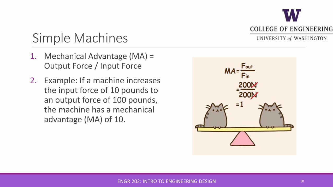
Simple Machines 1. Mechanical Advantage (MA) =
Output Force / Input Force
2. Example: If a machine increases the input force of 10 pounds to an output force of 100 pounds, the machine has a mechanical advantage (MA) of 10.
ENGR 202: INTRO TO ENGINEERING DESIGN 10

Simple Machines
No machine can increase both the magnitudeand the distance of a force at the same time.
ENGR 202: INTRO TO ENGINEERING DESIGN 11

The Lever1. A lever is a rigid bar that rotates
around a fixed point called the fulcrum.
2. The bar may be either straight or curved.
3. In use, a lever has both an effort (or applied) force and a load (resistive force).
ENGR 202: INTRO TO ENGINEERING DESIGN 12

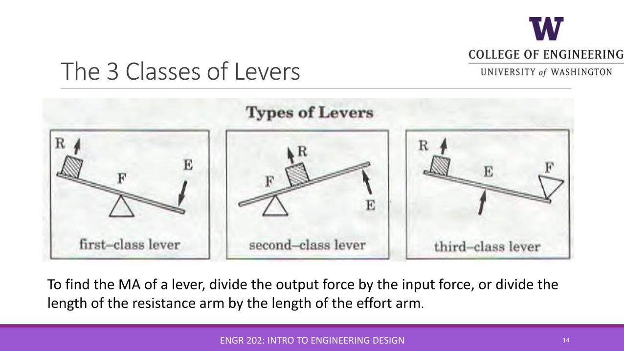
The 3 Classes of Levers
The class of a lever is determined by the location of the effort force and the loadrelative to the fulcrum.
ENGR 202: INTRO TO ENGINEERING DESIGN 13
The 3 Classes of Levers
ENGR 202: INTRO TO ENGINEERING DESIGN 14
To find the MA of a lever, divide the output force by the input force, or divide the length of the resistance arm by the length of the effort arm.

15
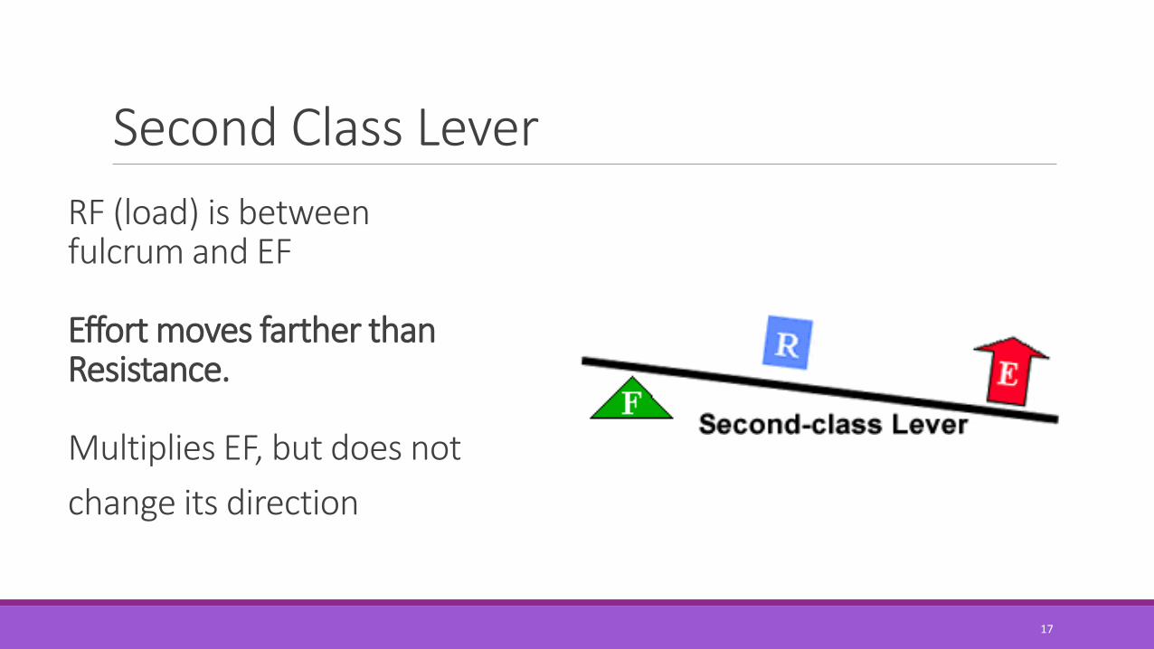
Fulcrum is between EF (effort) and RF (load)
Effort moves farther than Resistance.
Multiplies EF and changes its direction
First Class Lever
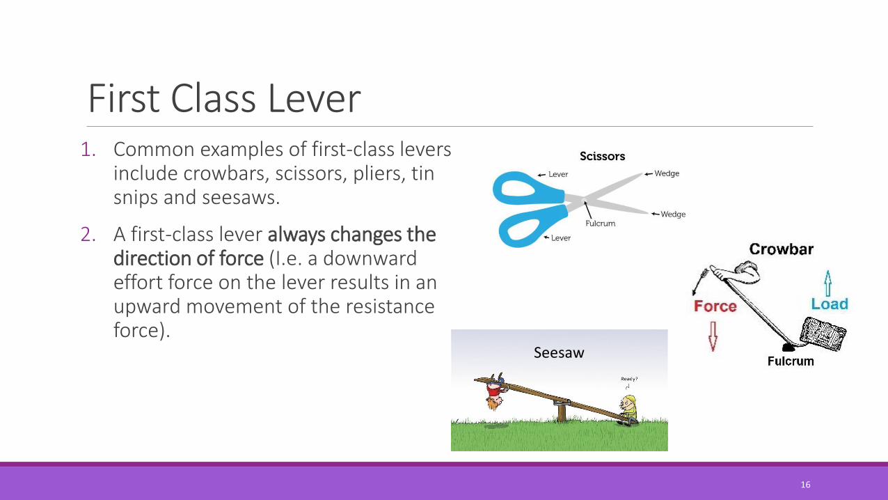
16
First Class Lever1. Common examples of first-class levers
include crowbars, scissors, pliers, tin snips and seesaws.
2. A first-class lever always changes the direction of force (I.e. a downward effort force on the lever results in an upward movement of the resistance force).
Seesaw
17
RF (load) is between fulcrum and EF
Effort moves farther than Resistance.
Multiplies EF, but does not
change its direction
Second Class Lever

18
Second Class Lever1. Common examples of second-
class levers include nut crackers, wheel barrows, doors, and bottle openers.
2. A second-class lever does not change the direction of force. When the fulcrum is located closer to the load than to the effort force, an increase in force (mechanical advantage) results.

19
EF is between fulcrum and RF (load) Does not multiply force
Resistance moves farther than Effort.
Multiplies the distance the effort
force travels
Third Class Lever

20
Third Class Lever1. Examples of third-class levers
include tweezers, hammers, and shovels.
2. A third-class lever does not change the direction of force; third-class levers always produce a gain in speed and distance and a corresponding decrease in force.
21
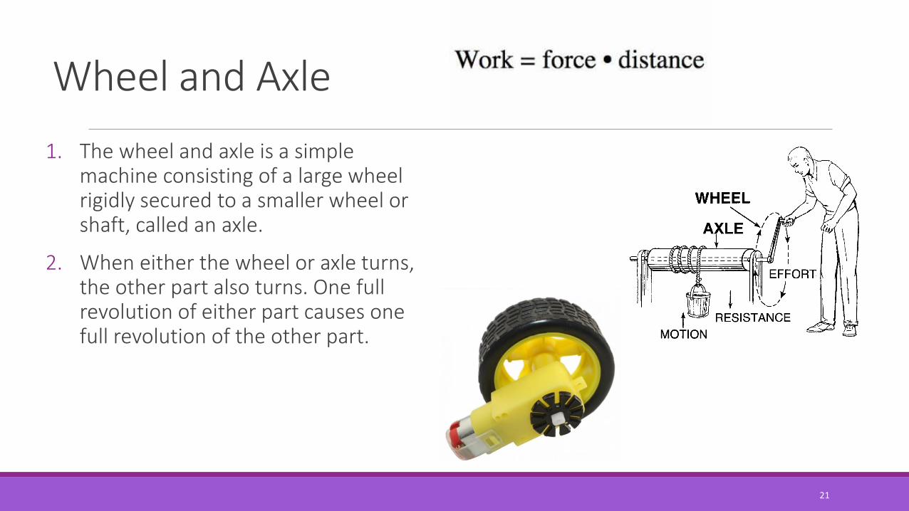
Wheel and Axle
1. The wheel and axle is a simple machine consisting of a large wheel rigidly secured to a smaller wheel or shaft, called an axle.
2. When either the wheel or axle turns, the other part also turns. One full revolution of either part causes one full revolution of the other part.
22
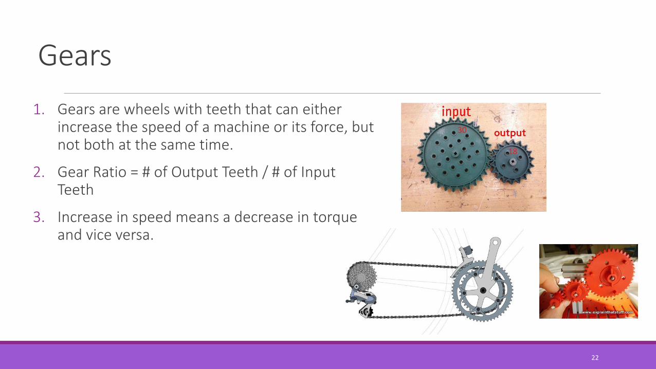
Gears
1. Gears are wheels with teeth that can either increase the speed of a machine or its force, but not both at the same time.
2. Gear Ratio = # of Output Teeth / # of Input Teeth
3. Increase in speed means a decrease in torque and vice versa.
23
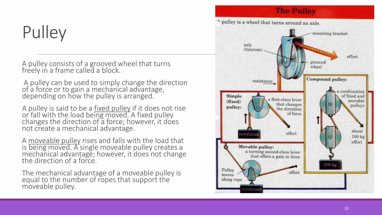
Pulley
A pulley consists of a grooved wheel that turns freely in a frame called a block.
A pulley can be used to simply change the direction of a force or to gain a mechanical advantage, depending on how the pulley is arranged.
A pulley is said to be a fixed pulley if it does not rise or fall with the load being moved. A fixed pulley changes the direction of a force; however, it does not create a mechanical advantage.
A moveable pulley rises and falls with the load that is being moved. A single moveable pulley creates a mechanical advantage; however, it does not change the direction of a force.
The mechanical advantage of a moveable pulley is equal to the number of ropes that support the moveable pulley.
24
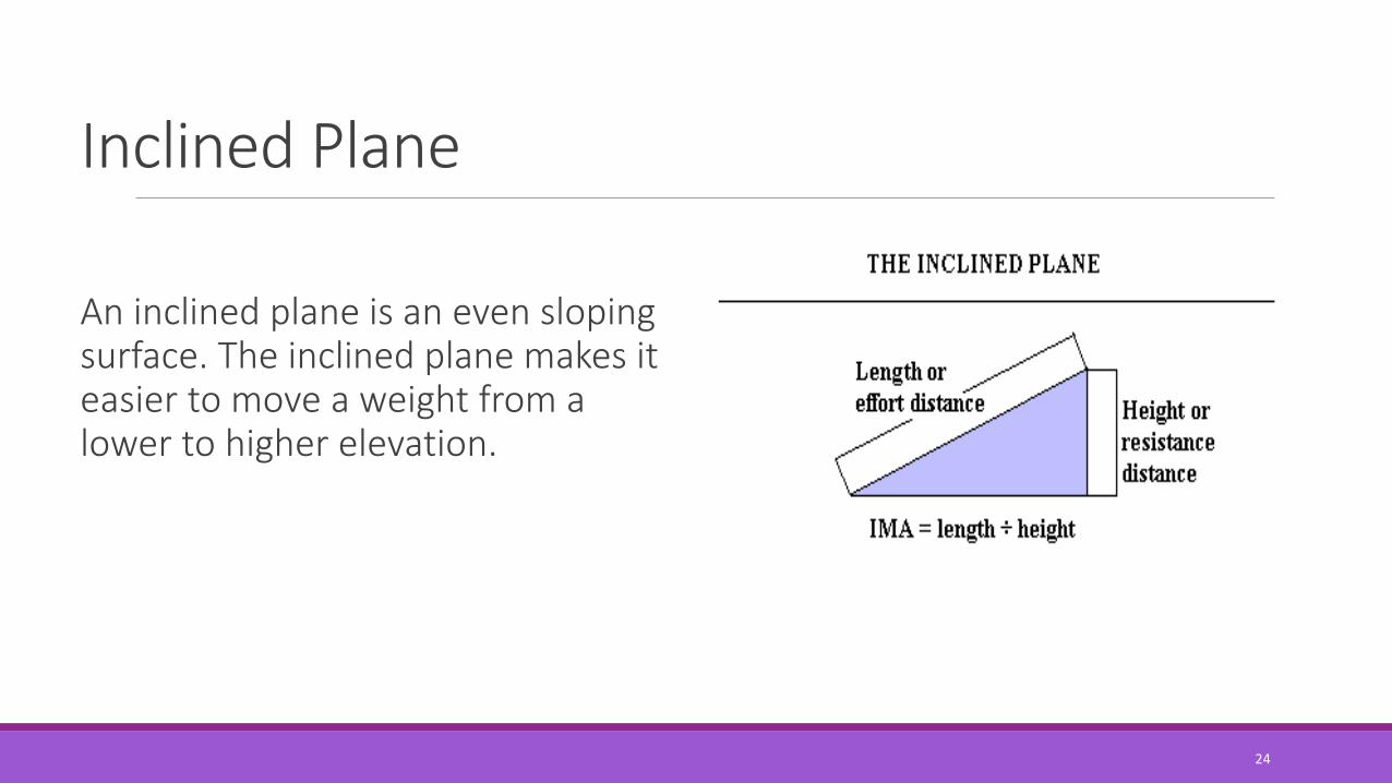
Inclined Plane
An inclined plane is an even sloping surface. The inclined plane makes it easier to move a weight from a lower to higher elevation.

25
Inclined Plane
The mechanical advantage of an inclined plane is equal to the length of the slope divided by the height of the inclined plane.
While the inclined plane produces a mechanical advantage, it does so by increasing the distance through which the force must move.
26
Inclined Plane
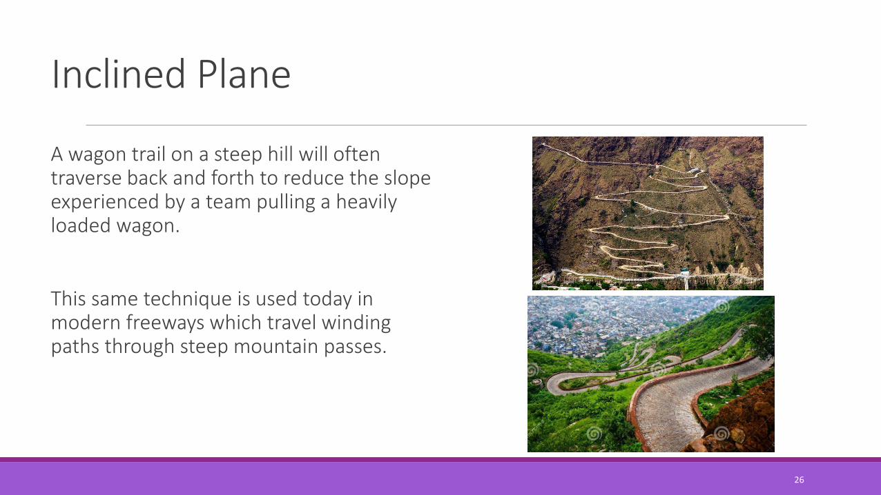
A wagon trail on a steep hill will often traverse back and forth to reduce the slope experienced by a team pulling a heavily loaded wagon.
This same technique is used today in modern freeways which travel winding paths through steep mountain passes.

27
Wedge
The wedge is a modification of the inclined plane. Wedges are used as either separating or holding devices.
A wedge can either be composed of one or two inclined planes. A double wedge can be thought of as two inclined planes joined together with their sloping surfaces outward.

28
Screw
1. The screw is also a modified version of the inclined plane.
2. While this may be somewhat difficult to visualize, it may help to think of the threads of the screw as a type of circular ramp (or inclined plane).
3. MA of an screw can be calculated by dividing the number of turns per inch.

Technical Design
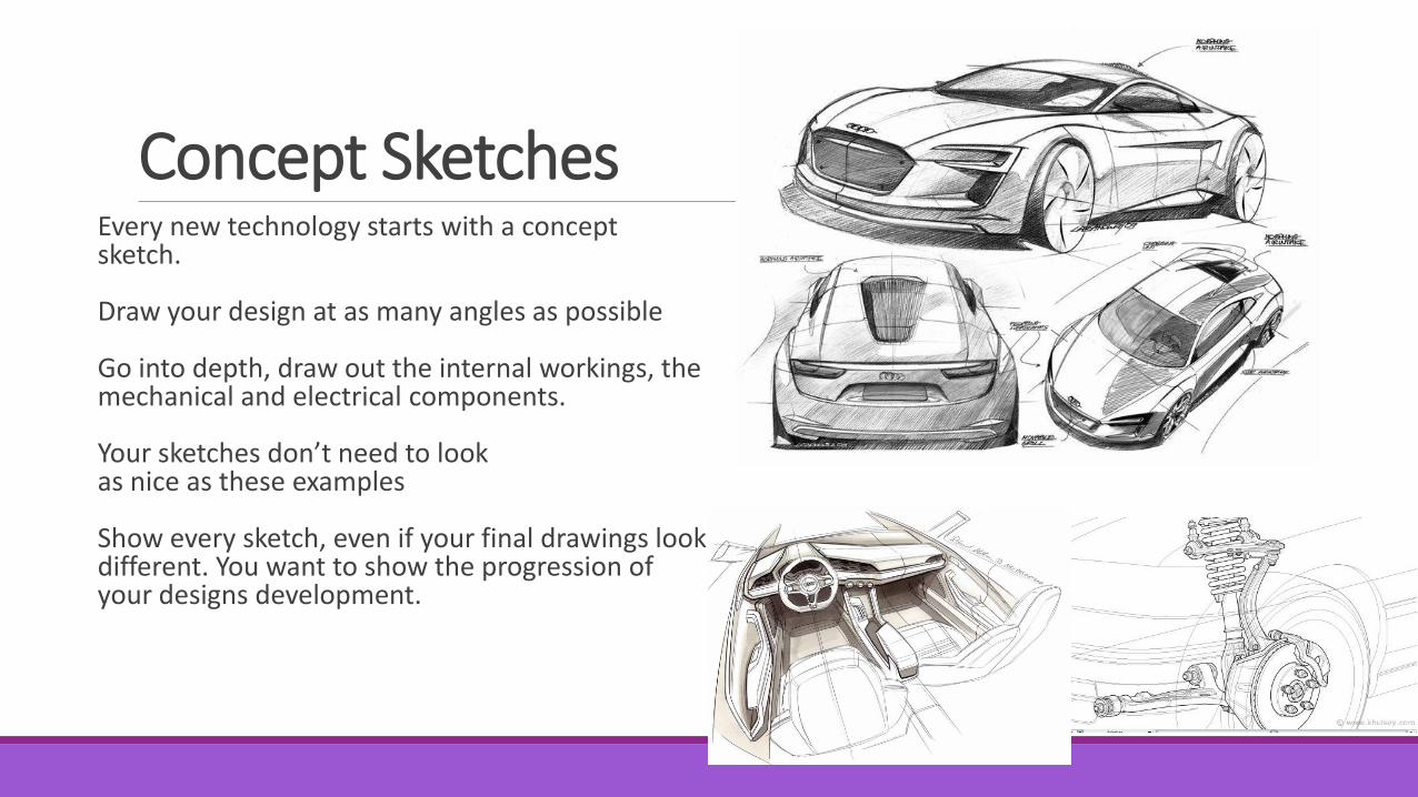
Concept SketchesEvery new technology starts with a concept sketch.
Draw your design at as many angles as possible
Go into depth, draw out the internal workings, the mechanical and electrical components.
Your sketches don’t need to look as nice as these examples
Show every sketch, even if your final drawings look different. You want to show the progression of your designs development.
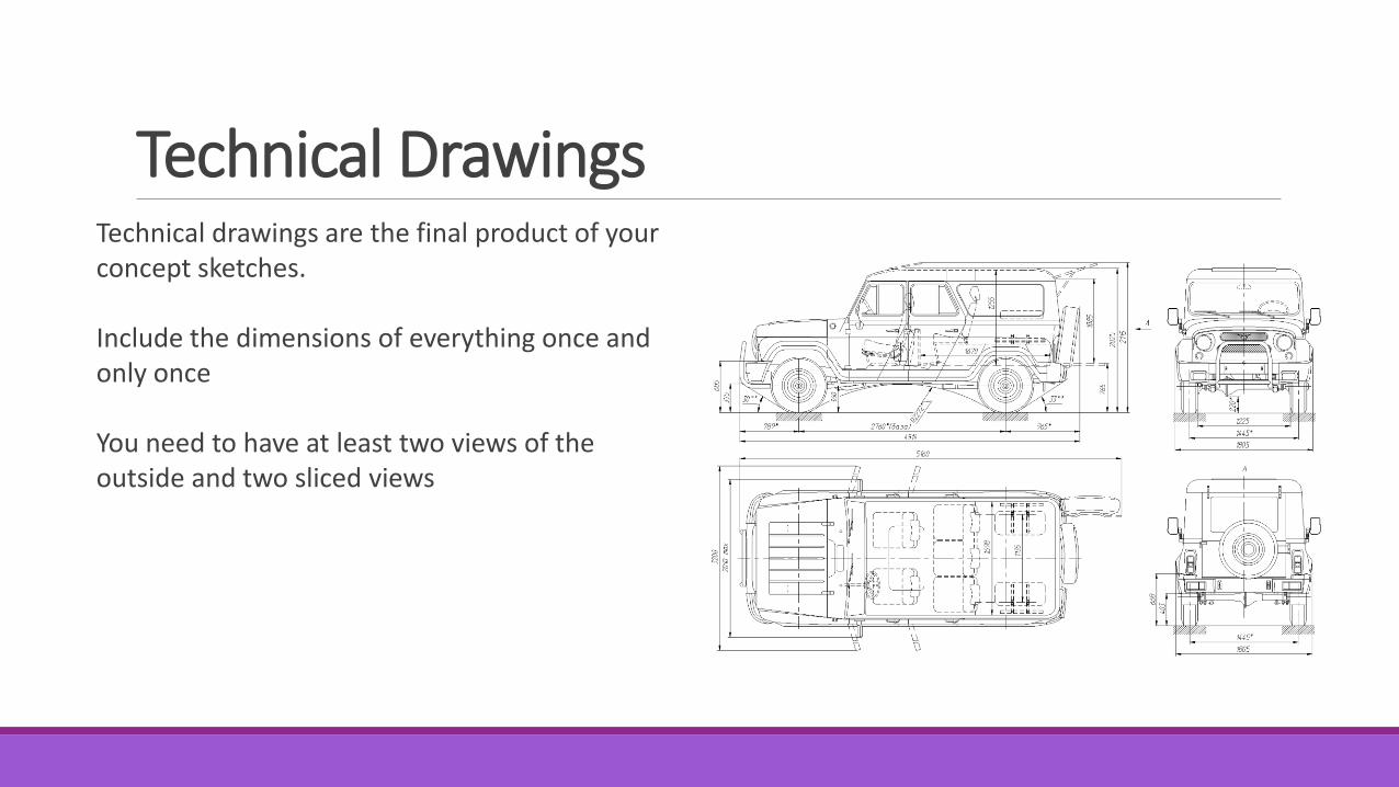
Technical DrawingsTechnical drawings are the final product of your concept sketches.
Include the dimensions of everything once and only once
You need to have at least two views of the outside and two sliced views

3D modellingIn this weeks lab you are going to learn how to 3D model in SolidWorks
Don’t start modelling your parts until you have finished at least a concept sketch and a rough technical drawing.
SolidWorks can be used to make more in depth technical drawings.