1-mbe900-05a.pdf - troubleshooting...table 15-5 ddec-vcu and ddec-ecu fault codes (3 of 7) (rev....
TRANSCRIPT
15 TROUBLESHOOTING
Section Page
15.1 TROUBLESHOOTING THE ELECTRONIC ENGINE CONTROL
SYSTEM .................................................................................................. 15-3
15.2 GENERAL TROUBLESHOOTING ........................................................... 15-11
15.3 FUEL INJECTION TROUBLESHOOTING ............................................... 15-24
15.4 MISFIRING CYLINDER ........................................................................... 15-46
15.5 STARTING DIFFICULTY (ENGINE ROTATES) ....................................... 15-56
15.6 NO START (ENGINE WILL NOT ROTATE) ............................................. 15-71
15.7 EXCESSIVE OIL CONSUMPTION .......................................................... 15-76
15.8 EXCESSIVE CRANKCASE PRESSURE ................................................. 15-83
15.9 EXCESSIVE EXHAUST SMOKE (BLACK OR GRAY) ............................ 15-90
15.10 EXCESSIVE BLUE SMOKE .................................................................... 15-107
15.11 EXCESSIVE WHITE SMOKE .................................................................. 15-112
15.12 ROUGH RUNNING OR STALLING .......................................................... 15-122
15.13 LACK OF POWER ................................................................................... 15-126
15.14 LOW OIL PRESSURE ............................................................................. 15-140
15.15 HIGH ENGINE COOLANT TEMPERATURE ........................................... 15-151
15.16 LOW COOLANT TEMPERATURE ........................................................... 15-162
15.17 POOR FUEL ECONOMY ......................................................................... 15-165

(Rev. 2005) All information subject to change without notice.
15-2 From Bulletin 1–MBE900–05 6SE414 0404 Copyright © 2005 DETROIT DIESEL CORPORATION

MBE900 SERVICE MANUAL
15.1 TROUBLESHOOTING THE ELECTRONIC ENGINE CONTROL SYSTEM
Prior to performing troubleshooting tasks familiarize yourself with Safety Instructions andPrecautions found in the General Information Section.
When the electronic engine control system detects a fault, it broadcasts a message on the datalink.The dash display will show the code "128," indicating there is an engine fault.
Troubleshooting problems and solutions for the MBE 900 engine are listed in Table 15-1 and 15-2.
Problem Recommended Solution
The Engine Will Not Crank Listed in Table 15-10
The Engine Turns Slowly Listed in Table 15-11
The Engine Cranks, But Won't Start Listed in Table 15-12
The Engine Starts Only After Cranking for a Long Time Listed in Table 15-13
The Engine Starts, But Dies Listed in Table 15-14
The Engine Fan Doesn't Work Listed in Table 15-15
The Engine Fan is Constantly On Listed in Table 15-16
Fuel Consumption is Too High Listed in Table 15-17
The Engine Performs Poorly, Does Not Develop FullPower
Listed in Table 15-18
The Engine is in Emergency Running Mode (constantspeed 1300 rpm)
Listed in Table 15-19
The Coolant Temperature is Above Normal Listed in Table 15-20
The Coolant Temperature is Below Normal Listed in Table 15-21
The Cooling System is Losing Coolant Listed in Table 15-22
There is Coolant in the Engine Oil Listed in Table 15-23
There is Foam in the Engine Oil Listed in Table 15-24
The Engine Oil Pressure is Low Listed in Table 15-25
The Engine Exhaust is White Listed in Table 15-26
The Engine Exhaust is Black Listed in Table 15-27
The Engine Exhaust is Blue Listed in Table 15-28
The Engine Brake Performance is Poor Listed in Table 15-29
Cruise Control is Not Working Listed in Table 15-30
The Fuel Pressure is Too High Downstream of the FuelFilter
Listed in Table 15-31
Fuel Flows Out of the Fuel Return Line Listed in Table 15-32
Table 15-1 Engine Troubleshooting Problems and Recommended Solutions(1 of 2)
All information subject to change without notice. (Rev. 2005)
6SE414 0404 Copyright © 2005 DETROIT DIESEL CORPORATION From Bulletin 1–MBE900–05 15-3
15.1 TROUBLESHOOTING THE ELECTRONIC ENGINE CONTROL SYSTEM
Problem Recommended Solution
Fuel Flow Quantity is Too Low at the Overflow Valve andToo High at the Filter
Listed in Table 15-33
Fuel Flow Quantity is Too Low at the Overflow Valve andWithin Range at the Filter
Listed in Table 15-34
The Fuel Inlet Pressure is Too Low Listed in Table 15-35
The Fuel Inlet Pressure is Too High Listed in Table 15-36
The Low Pressure Fuel System is Leaking Listed in Table 15-37
Table 15-2 Engine Troubleshooting Problems and Recommended Solutions(2 of 2)
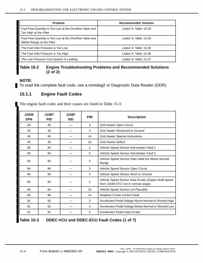
NOTE:To read the complete fault code, use a minidiag2 or Diagnostic Data Reader (DDR).
15.1.1 Engine Fault Codes
The engine fault codes and their causes are listed in Table 15-3:
J1939
SPN
J1587
PID
J1587
SIDFMI Description
45 45 — 3 Grid Heater Open Circuit
45 45 — 4 Grid Heater Shortened to Ground
45 45 — 14 Grid Heater Special Instructions
45 45 — 12 Grid Heater Defect
84 84 — 1 Vehicle Speed Sensor Anti-tamper Fault 1
84 84 — 5 Vehicle Speed Sensor Anti-tamper Fault 2
84 84 — 0Vehicle Speed Sensor Data Valid but Above NormalRange
84 84 — 3 Vehicle Speed Sensor Open Circuit
84 84 — 4 Vehicle Speed Sensor Short to Ground
84 84 — 2Vehicle Speed Sensor Data Erratic (Output shaft speedfrom J1939 ETCI not in normal range)
84 84 — 14 Vehicle Speed Sensor not Plausible
86 86 — 14 Adaptive Cruise Control Fault
91 91 — 3 Accelerator Pedal Voltage Above Normal or Shorted High
91 91 — 4 Accelerator Pedal Voltage Below Normal or Shorted Low
91 91 — 2 Accelerator Pedal Data Erratic
Table 15-3 DDEC-VCU and DDEC-ECU Fault Codes (1 of 7)
(Rev. 2005) All information subject to change without notice.
15-4 From Bulletin 1–MBE900–05 6SE414 0404 Copyright © 2005 DETROIT DIESEL CORPORATION
MBE900 SERVICE MANUAL
J1939
SPN
J1587
PID
J1587
SIDFMI Description
94 94 — 3 Fuel Pressure Sensor Open Circuit
94 94 — 4 Fuel Pressure Sensor Short to Ground
94 94 — 0 Fuel Pressure High
94 94 — 1 Fuel Pressure Low
94 94 — 2 Engine Fuel Pressure Sensor Data Not Correct
94 94 — 14Engine Fuel Pressure Sensor Measured Data NotCorrect
95 95 — 0 Fuel Restriction High
95 95 — 3 Fuel Restriction Circuit Failed High
95 95 — 4 Fuel Restriction Circuit Failed Low
98 98 — 14 Engine Oil Level Data Valid but Very low
98 98 — 0 Engine Oil Level High
98 98 — 1 Engine Oil Level Low
98 98 — 3 Engine Oil Level Sensor Voltage High
98 98 — 4 Engine Oil Level Sensor Voltage Low
98 98 — 5 Engine Oil Level Sensor Open Circuit
98 98 — 2 Engine Oil Level Too High or Too Low
100 100 — 1 Engine Oil Pressure Low
100 100 — 3 Engine Oil Pressure Sensor Open Circuit
100 100 — 2 Engine Oil Pressure Sensor Data Erratic
100 100 — 4 Engine Oil Pressure Sensor Short to Ground
100 100 — 14 Engine Oil Pressure Too Low
102 102 — 0 Boost Pressure High
102 102 — 1 Boost Pressure Low
102 102 — 2 Boost Pressure Sensor Data Erratic
102 102 — 3 Boost Pressure Sensor Open Circuit
102 102 — 4 Boost Pressure Sensor Short to Ground
102 102 — 13 Boost Pressure Out of Range
103 103 — 7 Turbocharger 1 No Rev
103 103 — 14 Turbocharger 2 No Rev
105 105 — 3 Intake Manifold Temperature Sensor Open Circuit
105 105 — 4 Intake Manifold Temperature Sensor Short to Ground
105 105 — 0 Intake Manifold Temperature High
107 107 — 0 Air Filter Restriction High
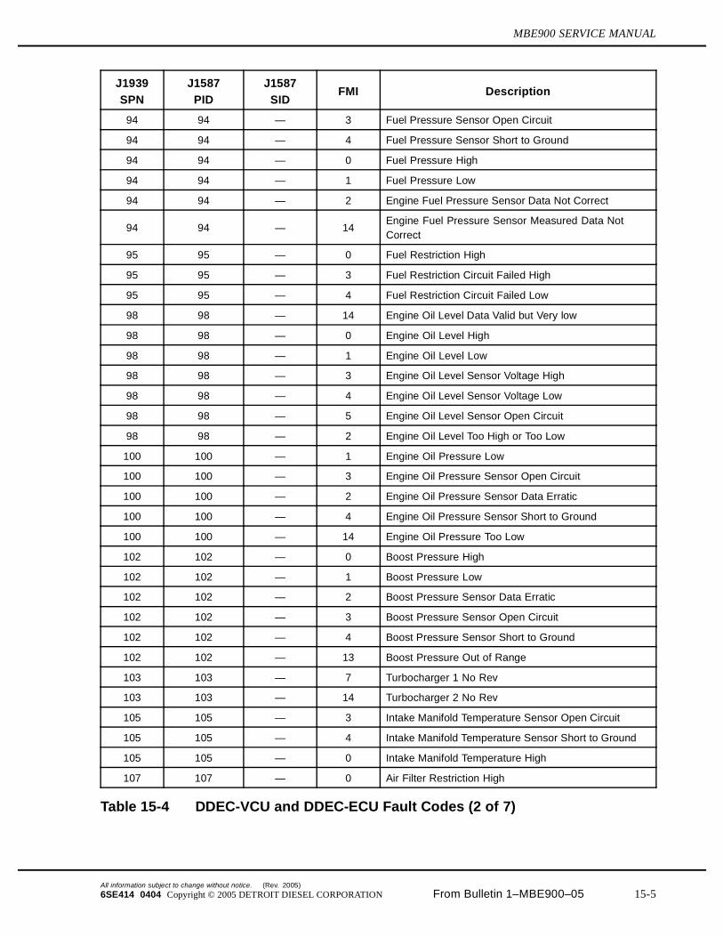
Table 15-4 DDEC-VCU and DDEC-ECU Fault Codes (2 of 7)
All information subject to change without notice. (Rev. 2005)
6SE414 0404 Copyright © 2005 DETROIT DIESEL CORPORATION From Bulletin 1–MBE900–05 15-5
15.1 TROUBLESHOOTING THE ELECTRONIC ENGINE CONTROL SYSTEM
J1939
SPN
J1587
PID
J1587
SIDFMI Description
107 107 — 3 Air Filter Sensor Open Circuit
107 107 — 4 Air Filter Sensor Short to Ground
110 110 — 14 Engine Coolant Temperature Very High
110 110 — 0 Engine Coolant Temperature High
110 110 — 4 Engine Coolant Temperature Sensor Short to Ground
110 110 — 3 Engine Coolant Temperature Sensor Open Circuit
111 111 — 1 Coolant Level Low
111 111 — 3 Coolant Level Sensor Open Circuit
111 111 — 4 Coolant Level Sensor Short to Ground
111 111 — 14 Coolant Level Very Low
— 123 — 7 Optimized Idle (OI) Loop Fault
158 158 — 0 Switched Battery Voltage High
158 158 — 1 Switched Battery Voltage Low
158 158 — 2Switched Battery Voltage Does Not match DDEC-ECUand DDEC-VCU
168 168 — 3 Battery Voltage High
168 168 — 4 Battery Voltage Low
174 174 — 3 Fuel Temperature Sensor Open Circuit
174 174 — 4 Fuel Temperature Sensor Short to Ground
175 175 — 3 Engine Oil Temperature Sensor Open Circuit
175 175 — 4 Engine Oil Temperature Sensor Short to Ground
190 190 — 0 Engine Speed High
216 — 216 14 Other DDEC-ECU Fault (Missing Information)
230 230 — 1 Idle Variation Switch (IVS) Wired Backwards
404 404 — 0 Turbo Compressor Out Temp High
404 404 — 1 Turbo Compressor Out Temp Low
527 — 254 12 Cruise Control – DDEC-VCU Internal Error
558 — 230 5 Idle Validation Switch (IVS) Open Circuit
558 — 230 12
Both Idle Validation Switches ClosedIdle Validation Switch (IVS) not Idle and AcceleratorPedal Signal IdleIdle Validation Switch Idle (IVS) and Accelerator PedalSignal not Idle
599 — 242 12Cruise Control Switch Contact Set + Coast — Both SETand RES Contacts Closed at the Same Time
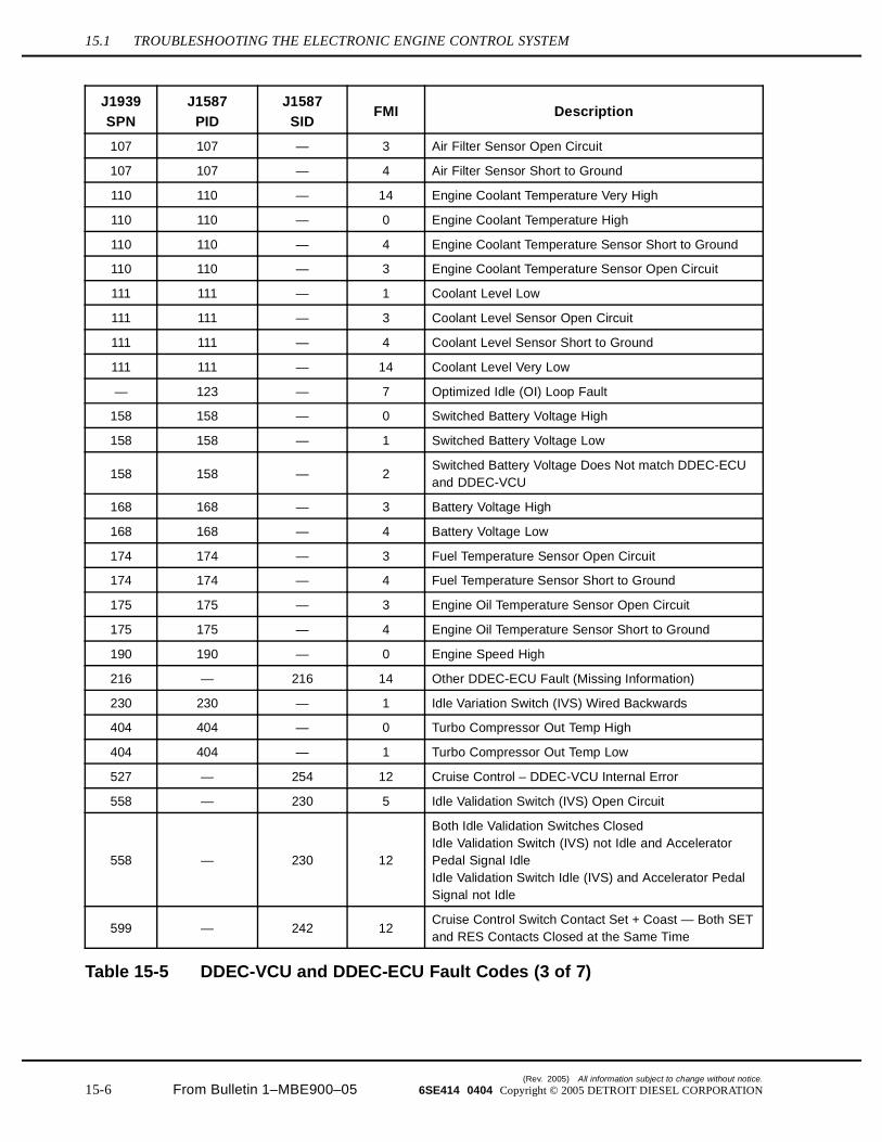
Table 15-5 DDEC-VCU and DDEC-ECU Fault Codes (3 of 7)
(Rev. 2005) All information subject to change without notice.
15-6 From Bulletin 1–MBE900–05 6SE414 0404 Copyright © 2005 DETROIT DIESEL CORPORATION
MBE900 SERVICE MANUAL
J1939
SPN
J1587
PID
J1587
SIDFMI Description
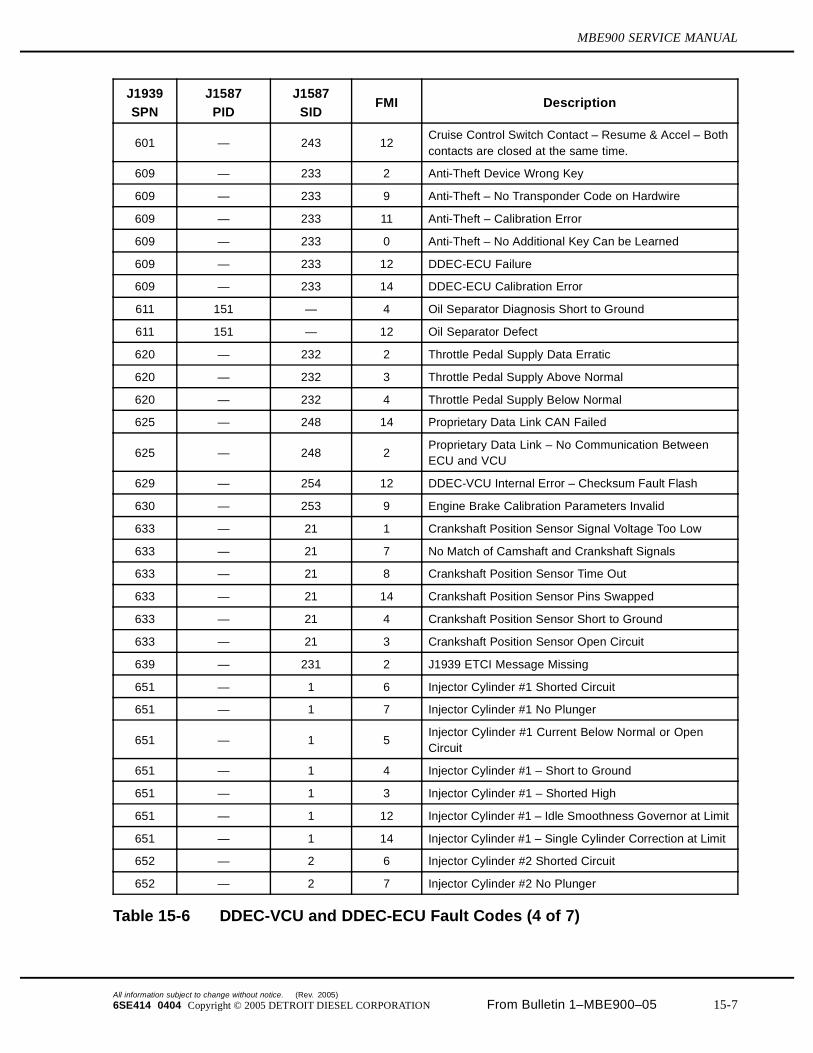
601 — 243 12Cruise Control Switch Contact – Resume & Accel – Bothcontacts are closed at the same time.
609 — 233 2 Anti-Theft Device Wrong Key
609 — 233 9 Anti-Theft – No Transponder Code on Hardwire
609 — 233 11 Anti-Theft – Calibration Error
609 — 233 0 Anti-Theft – No Additional Key Can be Learned
609 — 233 12 DDEC-ECU Failure
609 — 233 14 DDEC-ECU Calibration Error
611 151 — 4 Oil Separator Diagnosis Short to Ground
611 151 — 12 Oil Separator Defect
620 — 232 2 Throttle Pedal Supply Data Erratic
620 — 232 3 Throttle Pedal Supply Above Normal
620 — 232 4 Throttle Pedal Supply Below Normal
625 — 248 14 Proprietary Data Link CAN Failed
625 — 248 2Proprietary Data Link – No Communication BetweenECU and VCU
629 — 254 12 DDEC-VCU Internal Error – Checksum Fault Flash
630 — 253 9 Engine Brake Calibration Parameters Invalid
633 — 21 1 Crankshaft Position Sensor Signal Voltage Too Low
633 — 21 7 No Match of Camshaft and Crankshaft Signals
633 — 21 8 Crankshaft Position Sensor Time Out
633 — 21 14 Crankshaft Position Sensor Pins Swapped
633 — 21 4 Crankshaft Position Sensor Short to Ground
633 — 21 3 Crankshaft Position Sensor Open Circuit
639 — 231 2 J1939 ETCI Message Missing
651 — 1 6 Injector Cylinder #1 Shorted Circuit
651 — 1 7 Injector Cylinder #1 No Plunger
651 — 1 5Injector Cylinder #1 Current Below Normal or OpenCircuit
651 — 1 4 Injector Cylinder #1 – Short to Ground
651 — 1 3 Injector Cylinder #1 – Shorted High
651 — 1 12 Injector Cylinder #1 – Idle Smoothness Governor at Limit
651 — 1 14 Injector Cylinder #1 – Single Cylinder Correction at Limit
652 — 2 6 Injector Cylinder #2 Shorted Circuit
652 — 2 7 Injector Cylinder #2 No Plunger
Table 15-6 DDEC-VCU and DDEC-ECU Fault Codes (4 of 7)
All information subject to change without notice. (Rev. 2005)
6SE414 0404 Copyright © 2005 DETROIT DIESEL CORPORATION From Bulletin 1–MBE900–05 15-7
15.1 TROUBLESHOOTING THE ELECTRONIC ENGINE CONTROL SYSTEM
J1939
SPN
J1587
PID
J1587
SIDFMI Description
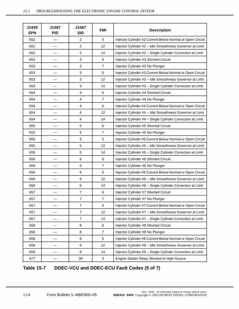
652 — 2 5 Injector Cylinder #2 Current Below Normal or Open Circuit
652 — 2 12 Injector Cylinder #2 – Idle Smoothness Governor at Limit
652 — 2 14 Injector Cylinder #2 – Single Cylinder Correction at Limit
653 — 3 6 Injector Cylinder #3 Shorted Circuit
653 — 3 7 Injector Cylinder #3 No Plunger
653 — 3 5 Injector Cylinder #3 Current Below Normal or Open Circuit
653 — 3 12 Injector Cylinder #3 – Idle Smoothness Governor at Limit
653 — 3 14 Injector Cylinder #3 – Single Cylinder Correction at Limit
654 — 4 6 Injector Cylinder #4 Shorted Circuit
654 — 4 7 Injector Cylinder #4 No Plunger
654 — 4 5 Injector Cylinder #4 Current Below Normal or Open Circuit
654 — 4 12 Injector Cylinder #4 – Idle Smoothness Governor at Limit
654 — 4 14 Injector Cylinder #4 – Single Cylinder Correction at Limit
655 — 5 6 Injector Cylinder #5 Shorted Circuit
655 — 5 7 Injector Cylinder #5 No Plunger
655 — 5 5 Injector Cylinder #5 Current Below Normal or Open Circuit
655 — 5 12 Injector Cylinder #5 – Idle Smoothness Governor at Limit
655 — 5 14 Injector Cylinder #5 – Single Cylinder Correction at Limit
656 — 6 6 Injector Cylinder #6 Shorted Circuit
656 — 6 7 Injector Cylinder #6 No Plunger
656 — 6 5 Injector Cylinder #6 Current Below Normal or Open Circuit
656 — 6 12 Injector Cylinder #6 – Idle Smoothness Governor at Limit
656 — 6 14 Injector Cylinder #6 – Single Cylinder Correction at Limit
657 — 7 6 Injector Cylinder #7 Shorted Circuit
657 — 7 7 Injector Cylinder #7 No Plunger
657 — 7 5 Injector Cylinder #7 Current Below Normal or Open Circuit
657 — 7 12 Injector Cylinder #7 – Idle Smoothness Governor at Limit
657 — 7 14 Injector Cylinder #7 – Single Cylinder Correction at Limit
658 — 8 6 Injector Cylinder #8 Shorted Circuit
658 — 8 7 Injector Cylinder #8 No Plunger
658 — 8 5 Injector Cylinder #8 Current Below Normal or Open Circuit
658 — 8 12 Injector Cylinder #8 – Idle Smoothness Governor at Limit
658 — 8 14 Injector Cylinder #8 – Single Cylinder Correction at Limit
677 — 39 3 Engine Starter Relay Shorted to High Source
Table 15-7 DDEC-VCU and DDEC-ECU Fault Codes (5 of 7)
(Rev. 2005) All information subject to change without notice.
15-8 From Bulletin 1–MBE900–05 6SE414 0404 Copyright © 2005 DETROIT DIESEL CORPORATION
MBE900 SERVICE MANUAL
J1939
SPN
J1587
PID
J1587
SIDFMI Description
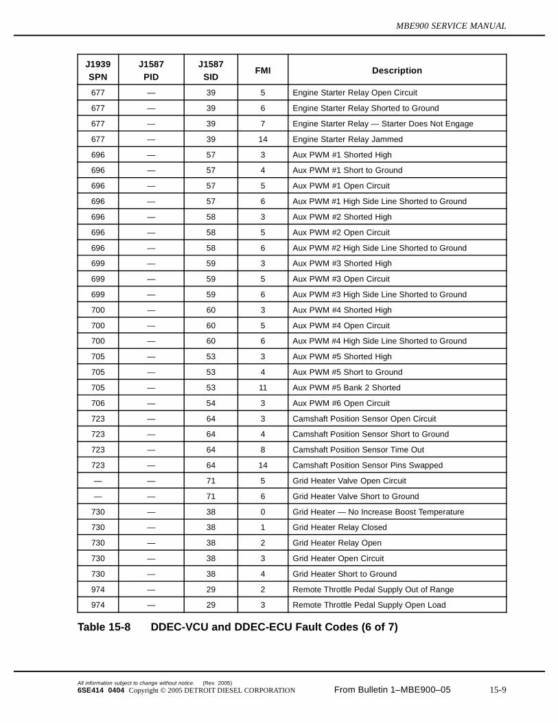
677 — 39 5 Engine Starter Relay Open Circuit
677 — 39 6 Engine Starter Relay Shorted to Ground
677 — 39 7 Engine Starter Relay — Starter Does Not Engage
677 — 39 14 Engine Starter Relay Jammed
696 — 57 3 Aux PWM #1 Shorted High
696 — 57 4 Aux PWM #1 Short to Ground
696 — 57 5 Aux PWM #1 Open Circuit
696 — 57 6 Aux PWM #1 High Side Line Shorted to Ground
696 — 58 3 Aux PWM #2 Shorted High
696 — 58 5 Aux PWM #2 Open Circuit
696 — 58 6 Aux PWM #2 High Side Line Shorted to Ground
699 — 59 3 Aux PWM #3 Shorted High
699 — 59 5 Aux PWM #3 Open Circuit
699 — 59 6 Aux PWM #3 High Side Line Shorted to Ground
700 — 60 3 Aux PWM #4 Shorted High
700 — 60 5 Aux PWM #4 Open Circuit
700 — 60 6 Aux PWM #4 High Side Line Shorted to Ground
705 — 53 3 Aux PWM #5 Shorted High
705 — 53 4 Aux PWM #5 Short to Ground
705 — 53 11 Aux PWM #5 Bank 2 Shorted
706 — 54 3 Aux PWM #6 Open Circuit
723 — 64 3 Camshaft Position Sensor Open Circuit
723 — 64 4 Camshaft Position Sensor Short to Ground
723 — 64 8 Camshaft Position Sensor Time Out
723 — 64 14 Camshaft Position Sensor Pins Swapped
— — 71 5 Grid Heater Valve Open Circuit
— — 71 6 Grid Heater Valve Short to Ground
730 — 38 0 Grid Heater — No Increase Boost Temperature
730 — 38 1 Grid Heater Relay Closed
730 — 38 2 Grid Heater Relay Open
730 — 38 3 Grid Heater Open Circuit
730 — 38 4 Grid Heater Short to Ground
974 — 29 2 Remote Throttle Pedal Supply Out of Range
974 — 29 3 Remote Throttle Pedal Supply Open Load
Table 15-8 DDEC-VCU and DDEC-ECU Fault Codes (6 of 7)
All information subject to change without notice. (Rev. 2005)
6SE414 0404 Copyright © 2005 DETROIT DIESEL CORPORATION From Bulletin 1–MBE900–05 15-9
15.1 TROUBLESHOOTING THE ELECTRONIC ENGINE CONTROL SYSTEM
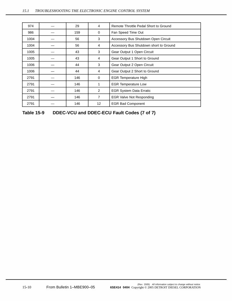
974 — 29 4 Remote Throttle Pedal Short to Ground
986 — 159 0 Fan Speed Time Out
1004 — 56 3 Accessory Bus Shutdown Open Circuit
1004 — 56 4 Accessory Bus Shutdown short to Ground
1005 — 43 3 Gear Output 1 Open Circuit
1005 — 43 4 Gear Output 1 Short to Ground
1006 — 44 3 Gear Output 2 Open Circuit
1006 — 44 4 Gear Output 2 Short to Ground
2791 — 146 0 EGR Temperature High
2791 — 146 1 EGR Temperature Low
2791 — 146 2 EGR System Data Erratic
2791 — 146 7 EGR Valve Not Responding
2791 — 146 12 EGR Bad Component
Table 15-9 DDEC-VCU and DDEC-ECU Fault Codes (7 of 7)
(Rev. 2005) All information subject to change without notice.
15-10 From Bulletin 1–MBE900–05 6SE414 0404 Copyright © 2005 DETROIT DIESEL CORPORATION
MBE900 SERVICE MANUAL
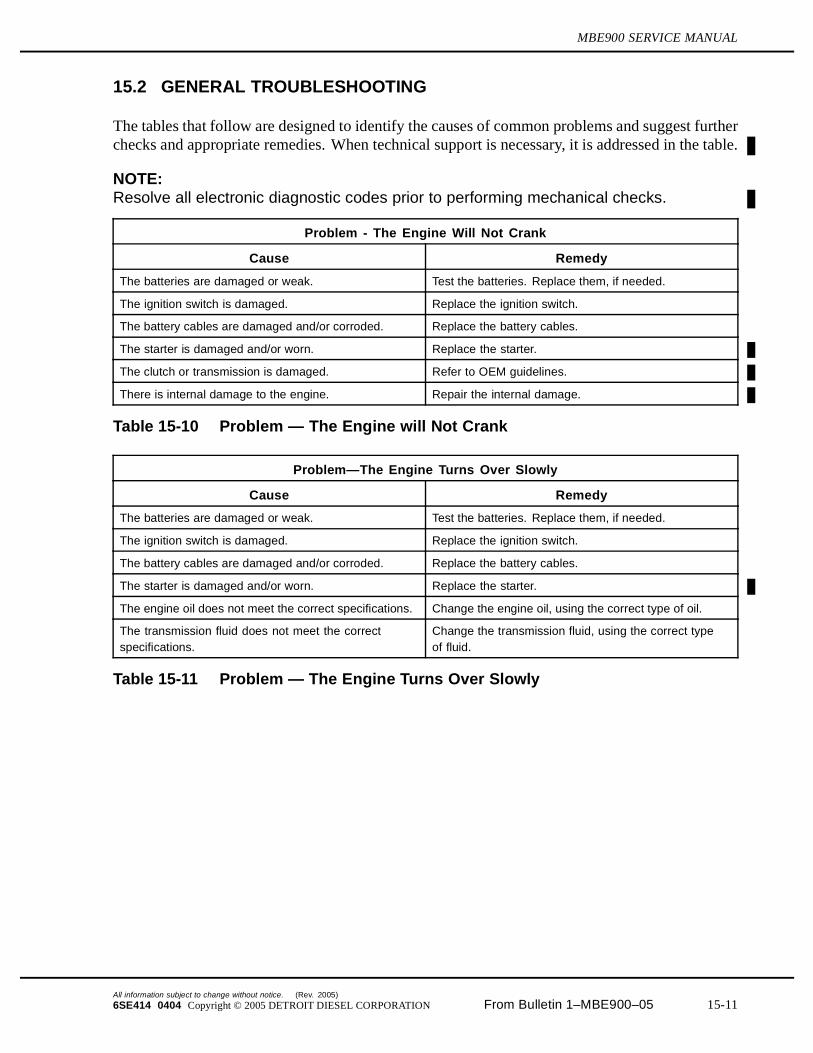
15.2 GENERAL TROUBLESHOOTING
The tables that follow are designed to identify the causes of common problems and suggest furtherchecks and appropriate remedies. When technical support is necessary, it is addressed in the table.
NOTE:Resolve all electronic diagnostic codes prior to performing mechanical checks.
Problem - The Engine Will Not Crank
Cause Remedy
The batteries are damaged or weak. Test the batteries. Replace them, if needed.
The ignition switch is damaged. Replace the ignition switch.
The battery cables are damaged and/or corroded. Replace the battery cables.
The starter is damaged and/or worn. Replace the starter.
The clutch or transmission is damaged. Refer to OEM guidelines.
There is internal damage to the engine. Repair the internal damage.
Table 15-10 Problem — The Engine will Not Crank
Problem—The Engine Turns Over Slowly
Cause Remedy
The batteries are damaged or weak. Test the batteries. Replace them, if needed.
The ignition switch is damaged. Replace the ignition switch.
The battery cables are damaged and/or corroded. Replace the battery cables.
The starter is damaged and/or worn. Replace the starter.
The engine oil does not meet the correct specifications. Change the engine oil, using the correct type of oil.
The transmission fluid does not meet the correctspecifications.
Change the transmission fluid, using the correct typeof fluid.
Table 15-11 Problem — The Engine Turns Over Slowly
All information subject to change without notice. (Rev. 2005)
6SE414 0404 Copyright © 2005 DETROIT DIESEL CORPORATION From Bulletin 1–MBE900–05 15-11
15.2 GENERAL TROUBLESHOOTING
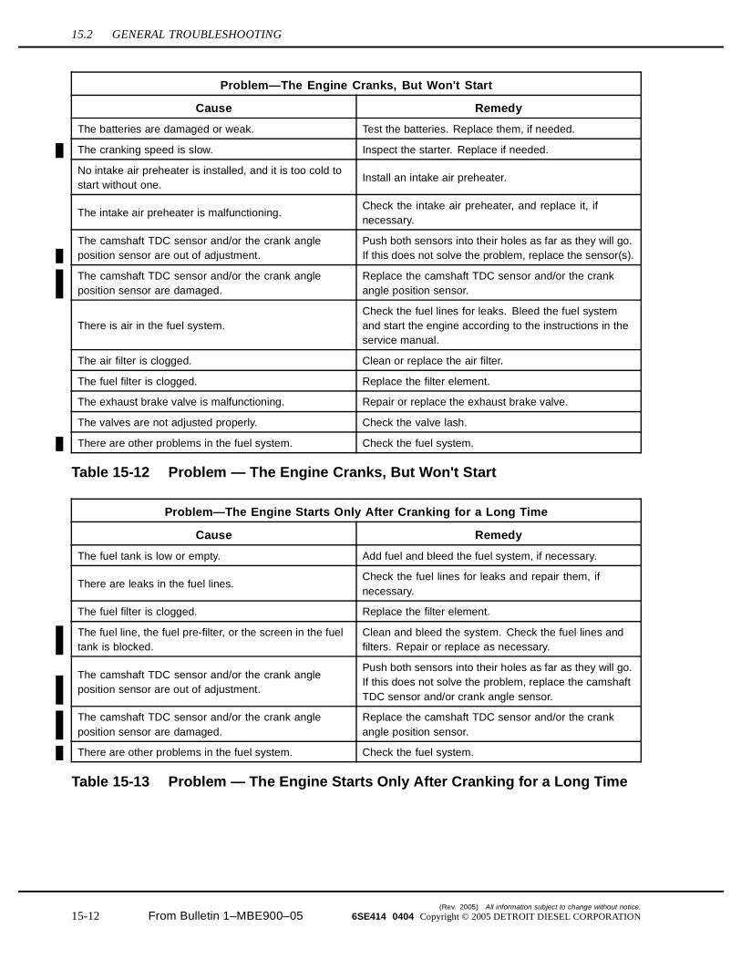
Problem—The Engine Cranks, But Won't Start
Cause Remedy
The batteries are damaged or weak. Test the batteries. Replace them, if needed.
The cranking speed is slow. Inspect the starter. Replace if needed.
No intake air preheater is installed, and it is too cold tostart without one.
Install an intake air preheater.
The intake air preheater is malfunctioning.Check the intake air preheater, and replace it, ifnecessary.
The camshaft TDC sensor and/or the crank angleposition sensor are out of adjustment.
Push both sensors into their holes as far as they will go.If this does not solve the problem, replace the sensor(s).
The camshaft TDC sensor and/or the crank angleposition sensor are damaged.
Replace the camshaft TDC sensor and/or the crankangle position sensor.
There is air in the fuel system.Check the fuel lines for leaks. Bleed the fuel systemand start the engine according to the instructions in theservice manual.
The air filter is clogged. Clean or replace the air filter.
The fuel filter is clogged. Replace the filter element.
The exhaust brake valve is malfunctioning. Repair or replace the exhaust brake valve.
The valves are not adjusted properly. Check the valve lash.
There are other problems in the fuel system. Check the fuel system.
Table 15-12 Problem — The Engine Cranks, But Won't Start
Problem—The Engine Starts Only After Cranking for a Long Time
Cause Remedy
The fuel tank is low or empty. Add fuel and bleed the fuel system, if necessary.
There are leaks in the fuel lines.Check the fuel lines for leaks and repair them, ifnecessary.
The fuel filter is clogged. Replace the filter element.
The fuel line, the fuel pre-filter, or the screen in the fueltank is blocked.
Clean and bleed the system. Check the fuel lines andfilters. Repair or replace as necessary.
The camshaft TDC sensor and/or the crank angleposition sensor are out of adjustment.
Push both sensors into their holes as far as they will go.If this does not solve the problem, replace the camshaftTDC sensor and/or crank angle sensor.
The camshaft TDC sensor and/or the crank angleposition sensor are damaged.
Replace the camshaft TDC sensor and/or the crankangle position sensor.
There are other problems in the fuel system. Check the fuel system.
Table 15-13 Problem — The Engine Starts Only After Cranking for a Long Time
(Rev. 2005) All information subject to change without notice.
15-12 From Bulletin 1–MBE900–05 6SE414 0404 Copyright © 2005 DETROIT DIESEL CORPORATION
MBE900 SERVICE MANUAL
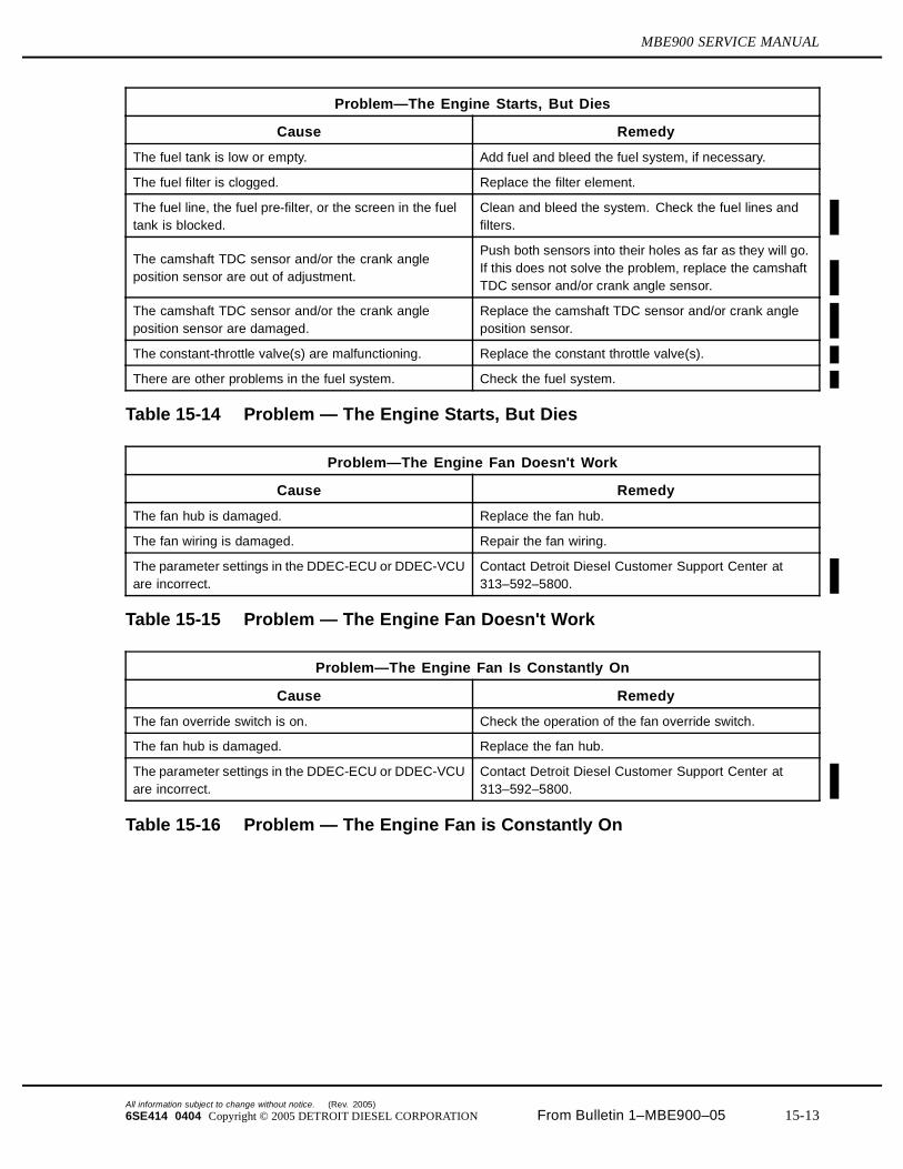
Problem—The Engine Starts, But Dies
Cause Remedy
The fuel tank is low or empty. Add fuel and bleed the fuel system, if necessary.
The fuel filter is clogged. Replace the filter element.
The fuel line, the fuel pre-filter, or the screen in the fueltank is blocked.
Clean and bleed the system. Check the fuel lines andfilters.
The camshaft TDC sensor and/or the crank angleposition sensor are out of adjustment.
Push both sensors into their holes as far as they will go.If this does not solve the problem, replace the camshaftTDC sensor and/or crank angle sensor.
The camshaft TDC sensor and/or the crank angleposition sensor are damaged.
Replace the camshaft TDC sensor and/or crank angleposition sensor.
The constant-throttle valve(s) are malfunctioning. Replace the constant throttle valve(s).
There are other problems in the fuel system. Check the fuel system.
Table 15-14 Problem — The Engine Starts, But Dies
Problem—The Engine Fan Doesn't Work
Cause Remedy
The fan hub is damaged. Replace the fan hub.
The fan wiring is damaged. Repair the fan wiring.
The parameter settings in the DDEC-ECU or DDEC-VCUare incorrect.
Contact Detroit Diesel Customer Support Center at313–592–5800.
Table 15-15 Problem — The Engine Fan Doesn't Work
Problem—The Engine Fan Is Constantly On
Cause Remedy
The fan override switch is on. Check the operation of the fan override switch.
The fan hub is damaged. Replace the fan hub.
The parameter settings in the DDEC-ECU or DDEC-VCUare incorrect.
Contact Detroit Diesel Customer Support Center at313–592–5800.
Table 15-16 Problem — The Engine Fan is Constantly On
All information subject to change without notice. (Rev. 2005)
6SE414 0404 Copyright © 2005 DETROIT DIESEL CORPORATION From Bulletin 1–MBE900–05 15-13
15.2 GENERAL TROUBLESHOOTING
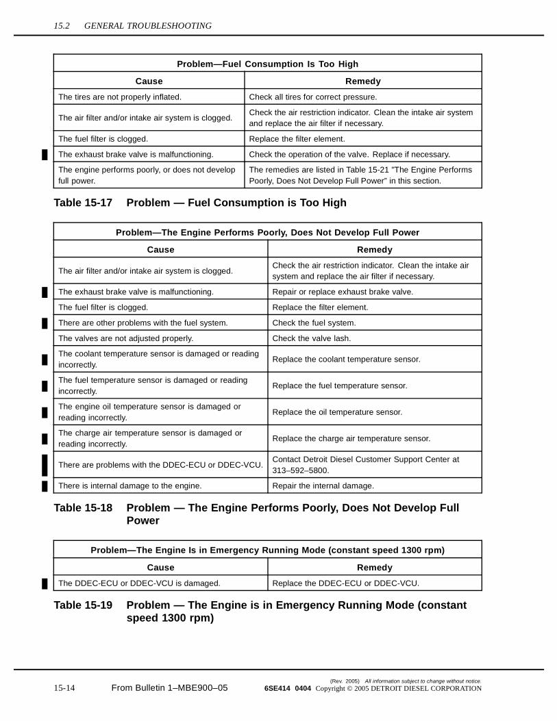
Problem—Fuel Consumption Is Too High
Cause Remedy
The tires are not properly inflated. Check all tires for correct pressure.
The air filter and/or intake air system is clogged.Check the air restriction indicator. Clean the intake air systemand replace the air filter if necessary.
The fuel filter is clogged. Replace the filter element.
The exhaust brake valve is malfunctioning. Check the operation of the valve. Replace if necessary.
The engine performs poorly, or does not developfull power.
The remedies are listed in Table 15-21 "The Engine PerformsPoorly, Does Not Develop Full Power” in this section.
Table 15-17 Problem — Fuel Consumption is Too High
Problem—The Engine Performs Poorly, Does Not Develop Full Power
Cause Remedy
The air filter and/or intake air system is clogged.Check the air restriction indicator. Clean the intake airsystem and replace the air filter if necessary.
The exhaust brake valve is malfunctioning. Repair or replace exhaust brake valve.
The fuel filter is clogged. Replace the filter element.
There are other problems with the fuel system. Check the fuel system.
The valves are not adjusted properly. Check the valve lash.
The coolant temperature sensor is damaged or readingincorrectly.
Replace the coolant temperature sensor.
The fuel temperature sensor is damaged or readingincorrectly.
Replace the fuel temperature sensor.
The engine oil temperature sensor is damaged orreading incorrectly.
Replace the oil temperature sensor.
The charge air temperature sensor is damaged orreading incorrectly.
Replace the charge air temperature sensor.
There are problems with the DDEC-ECU or DDEC-VCU.Contact Detroit Diesel Customer Support Center at313–592–5800.
There is internal damage to the engine. Repair the internal damage.
Table 15-18 Problem — The Engine Performs Poorly, Does Not Develop FullPower
Problem—The Engine Is in Emergency Running Mode (constant speed 1300 rpm)
Cause Remedy
The DDEC-ECU or DDEC-VCU is damaged. Replace the DDEC-ECU or DDEC-VCU.
Table 15-19 Problem — The Engine is in Emergency Running Mode (constantspeed 1300 rpm)
(Rev. 2005) All information subject to change without notice.
15-14 From Bulletin 1–MBE900–05 6SE414 0404 Copyright © 2005 DETROIT DIESEL CORPORATION
MBE900 SERVICE MANUAL
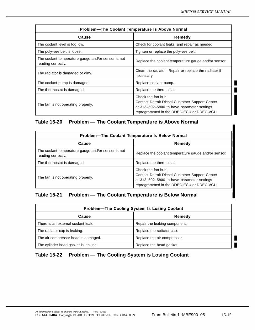
Problem—The Coolant Temperature Is Above Normal
Cause Remedy
The coolant level is too low. Check for coolant leaks, and repair as needed.
The poly-vee belt is loose. Tighten or replace the poly-vee belt.
The coolant temperature gauge and/or sensor is notreading correctly.
Replace the coolant temperature gauge and/or sensor.
The radiator is damaged or dirty.Clean the radiator. Repair or replace the radiator ifnecessary.
The coolant pump is damaged. Replace coolant pump.
The thermostat is damaged. Replace the thermostat.
The fan is not operating properly.
Check the fan hub.Contact Detroit Diesel Customer Support Centerat 313–592–5800 to have parameter settingsreprogrammed in the DDEC-ECU or DDEC-VCU.
Table 15-20 Problem — The Coolant Temperature is Above Normal
Problem—The Coolant Temperature Is Below Normal
Cause Remedy
The coolant temperature gauge and/or sensor is notreading correctly.
Replace the coolant temperature gauge and/or sensor.
The thermostat is damaged. Replace the thermostat.
The fan is not operating properly.
Check the fan hub.Contact Detroit Diesel Customer Support Centerat 313–592–5800 to have parameter settingsreprogrammed in the DDEC-ECU or DDEC-VCU.
Table 15-21 Problem — The Coolant Temperature is Below Normal
Problem—The Cooling System Is Losing Coolant
Cause Remedy
There is an external coolant leak. Repair the leaking component.
The radiator cap is leaking. Replace the radiator cap.
The air compressor head is damaged. Replace the air compressor.
The cylinder head gasket is leaking. Replace the head gasket.
Table 15-22 Problem — The Cooling System is Losing Coolant
All information subject to change without notice. (Rev. 2005)
6SE414 0404 Copyright © 2005 DETROIT DIESEL CORPORATION From Bulletin 1–MBE900–05 15-15
15.2 GENERAL TROUBLESHOOTING
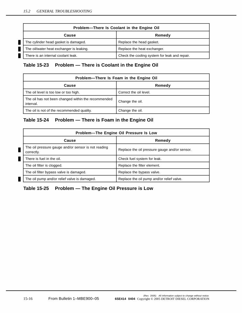
Problem—There Is Coolant in the Engine Oil
Cause Remedy
The cylinder head gasket is damaged. Replace the head gasket.
The oil/water heat exchanger is leaking. Replace the heat exchanger.
There is an internal coolant leak. Check the cooling system for leak and repair.
Table 15-23 Problem — There is Coolant in the Engine Oil
Problem—There Is Foam in the Engine Oil
Cause Remedy
The oil level is too low or too high. Correct the oil level.
The oil has not been changed within the recommendedinterval.
Change the oil.
The oil is not of the recommended quality. Change the oil.
Table 15-24 Problem — There is Foam in the Engine Oil
Problem—The Engine Oil Pressure Is Low
Cause Remedy
The oil pressure gauge and/or sensor is not readingcorrectly.
Replace the oil pressure gauge and/or sensor.
There is fuel in the oil. Check fuel system for leak.
The oil filter is clogged. Replace the filter element.
The oil filter bypass valve is damaged. Replace the bypass valve.
The oil pump and/or relief valve is damaged. Replace the oil pump and/or relief valve.
Table 15-25 Problem — The Engine Oil Pressure is Low
(Rev. 2005) All information subject to change without notice.
15-16 From Bulletin 1–MBE900–05 6SE414 0404 Copyright © 2005 DETROIT DIESEL CORPORATION
MBE900 SERVICE MANUAL
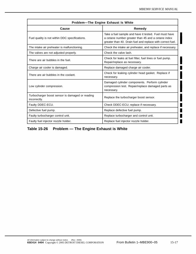
Problem—The Engine Exhaust Is White
Cause Remedy
Fuel quality is not within DDC specifications.Take a fuel sample and have it tested. Fuel must havea cetane number greater than 45 and a cetane indexgreater than 40. Drain fuel and replace with correct fuel.
The intake air preheater is malfunctioning. Check the intake air preheater, and replace if necessary.
The valves are not adjusted properly. Check the valve lash.
There are air bubbles in the fuel.Check for leaks at fuel filter, fuel lines or fuel pump.Repair/replace as necessary.
Charge air cooler is damaged. Replace damaged charge air cooler.
There are air bubbles in the coolant.Check for leaking cylinder head gasket. Replace ifnecessary.
Low cylinder compression.Damaged cylinder components. Perform cylindercompression test. Repair/replace damaged parts asnecessary.
Turbocharger boost sensor is damaged or readingincorrectly.
Replace the turbocharger boost sensor.
Faulty DDEC-ECU. Check DDEC-ECU; replace if necessary.
Defective fuel pump. Replace defective fuel pump.
Faulty turbocharger control unit. Replace turbocharger and control unit.
Faulty fuel injector nozzle holder. Replace fuel injector nozzle holder.
Table 15-26 Problem — The Engine Exhaust is White
All information subject to change without notice. (Rev. 2005)
6SE414 0404 Copyright © 2005 DETROIT DIESEL CORPORATION From Bulletin 1–MBE900–05 15-17
15.2 GENERAL TROUBLESHOOTING
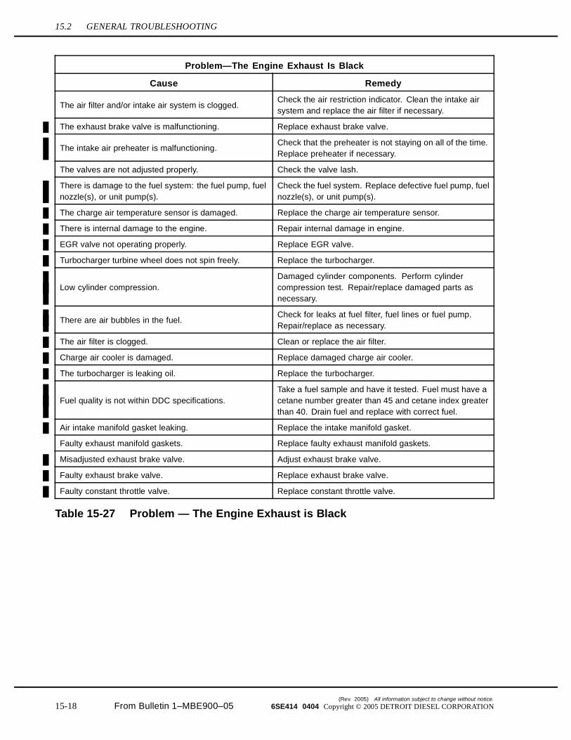
Problem—The Engine Exhaust Is Black
Cause Remedy
The air filter and/or intake air system is clogged.Check the air restriction indicator. Clean the intake airsystem and replace the air filter if necessary.
The exhaust brake valve is malfunctioning. Replace exhaust brake valve.
The intake air preheater is malfunctioning.Check that the preheater is not staying on all of the time.Replace preheater if necessary.
The valves are not adjusted properly. Check the valve lash.
There is damage to the fuel system: the fuel pump, fuelnozzle(s), or unit pump(s).
Check the fuel system. Replace defective fuel pump, fuelnozzle(s), or unit pump(s).
The charge air temperature sensor is damaged. Replace the charge air temperature sensor.
There is internal damage to the engine. Repair internal damage in engine.
EGR valve not operating properly. Replace EGR valve.
Turbocharger turbine wheel does not spin freely. Replace the turbocharger.
Low cylinder compression.Damaged cylinder components. Perform cylindercompression test. Repair/replace damaged parts asnecessary.
There are air bubbles in the fuel.Check for leaks at fuel filter, fuel lines or fuel pump.Repair/replace as necessary.
The air filter is clogged. Clean or replace the air filter.
Charge air cooler is damaged. Replace damaged charge air cooler.
The turbocharger is leaking oil. Replace the turbocharger.
Fuel quality is not within DDC specifications.Take a fuel sample and have it tested. Fuel must have acetane number greater than 45 and cetane index greaterthan 40. Drain fuel and replace with correct fuel.
Air intake manifold gasket leaking. Replace the intake manifold gasket.
Faulty exhaust manifold gaskets. Replace faulty exhaust manifold gaskets.
Misadjusted exhaust brake valve. Adjust exhaust brake valve.
Faulty exhaust brake valve. Replace exhaust brake valve.
Faulty constant throttle valve. Replace constant throttle valve.
Table 15-27 Problem — The Engine Exhaust is Black
(Rev. 2005) All information subject to change without notice.
15-18 From Bulletin 1–MBE900–05 6SE414 0404 Copyright © 2005 DETROIT DIESEL CORPORATION
MBE900 SERVICE MANUAL
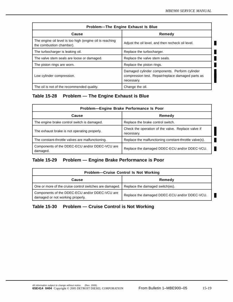
Problem—The Engine Exhaust Is Blue
Cause Remedy
The engine oil level is too high (engine oil is reachingthe combustion chamber).
Adjust the oil level, and then recheck oil level.
The turbocharger is leaking oil. Replace the turbocharger.
The valve stem seals are loose or damaged. Replace the valve stem seals.
The piston rings are worn. Replace the piston rings.
Low cylinder compression.Damaged cylinder components. Perform cylindercompression test. Repair/replace damaged parts asnecessary.
The oil is not of the recommended quality. Change the oil.
Table 15-28 Problem — The Engine Exhaust is Blue
Problem—Engine Brake Performance Is Poor
Cause Remedy
The engine brake control switch is damaged. Replace the brake control switch.
The exhaust brake is not operating properly.Check the operation of the valve. Replace valve ifnecessary.
The constant-throttle valves are malfunctioning. Replace the malfunctioning constant-throttle valve(s).
Components of the DDEC-ECU and/or DDEC-VCU aredamaged.
Replace the damaged DDEC-ECU and/or DDEC-VCU.
Table 15-29 Problem — Engine Brake Performance is Poor
Problem—Cruise Control Is Not Working
Cause Remedy
One or more of the cruise control switches are damaged. Replace the damaged switch(es).
Components of the DDEC-ECU and/or DDEC-VCU aredamaged or not working properly.
Replace the damaged DDEC-ECU and/or DDEC-VCU.
Table 15-30 Problem — Cruise Control is Not Working
All information subject to change without notice. (Rev. 2005)
6SE414 0404 Copyright © 2005 DETROIT DIESEL CORPORATION From Bulletin 1–MBE900–05 15-19
15.2 GENERAL TROUBLESHOOTING
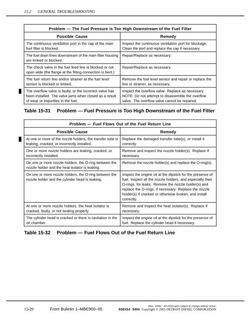
Problem — The Fuel Pressure is Too High Downstream of the Fuel Filter
Possible Cause Remedy
The continuous ventilation port in the cap of the mainfuel filter is blocked.
Inspect the continuous ventilation port for blockage.Clean the port and replace the cap if necessary.
The fuel drain lines downstream of the main filter housingare kinked or blocked.
Repair/Replace as necessary.
The check valve in the fuel feed line is blocked or notopen wide (the flange at the fitting connection is bent.)
Repair/Replace as necessary.
The fuel return line and/or strainer at the fuel levelsensor is blocked or kinked.
Remove the fuel level sensor and repair or replace theline or strainer, as necessary.
The overflow valve is faulty, or the incorrect valve hasbeen installed. The valve jams when closed as a resultof wear or impurities in the fuel.
Inspect the overflow valve. Replace as necessary.NOTE: Do not attempt to disassemble the overflowvalve. The overflow valve cannot be repaired.
Table 15-31 Problem — Fuel Pressure is Too High Downstream of the Fuel Filter
Problem — Fuel Flows Out of the Fuel Return Line
Possible Cause Remedy
At one or more of the nozzle holders, the transfer tube isleaking, cracked, or incorrectly installed.
Replace the damaged transfer tube(s), or install itcorrectly.
One or more nozzle holders are leaking, cracked, orincorrectly installed.
Remove and inspect the nozzle holder(s). Replace ifnecessary.
On one or more nozzle holders, the O-ring between thenozzle holder and the heat isolator is leaking.
Remove the nozzle holder(s) and replace the O-ring(s).
On one or more nozzle holders, the O-ring between thenozzle holder and the cylinder head is leaking.
Inspect the engine oil at the dipstick for the presence offuel. Inspect all the nozzle holders, and especially theirO-rings, for leaks. Remove the nozzle holder(s) andreplace the O-rings, if necessary. Replace the nozzleholder(s) if cracked or otherwise broken, and installcorrectly.
At one or more nozzle holders, the heat isolator iscracked, faulty, or not sealing properly.
Remove and inspect the heat isolator(s). Replace ifnecessary.
The cylinder head is cracked or there is cavitation in theoil chamber.
Inspect the engine oil at the dipstick for the presence offuel. Replace the cylinder head if necessary.
Table 15-32 Problem — Fuel Flows Out of the Fuel Return Line
(Rev. 2005) All information subject to change without notice.
15-20 From Bulletin 1–MBE900–05 6SE414 0404 Copyright © 2005 DETROIT DIESEL CORPORATION
MBE900 SERVICE MANUAL
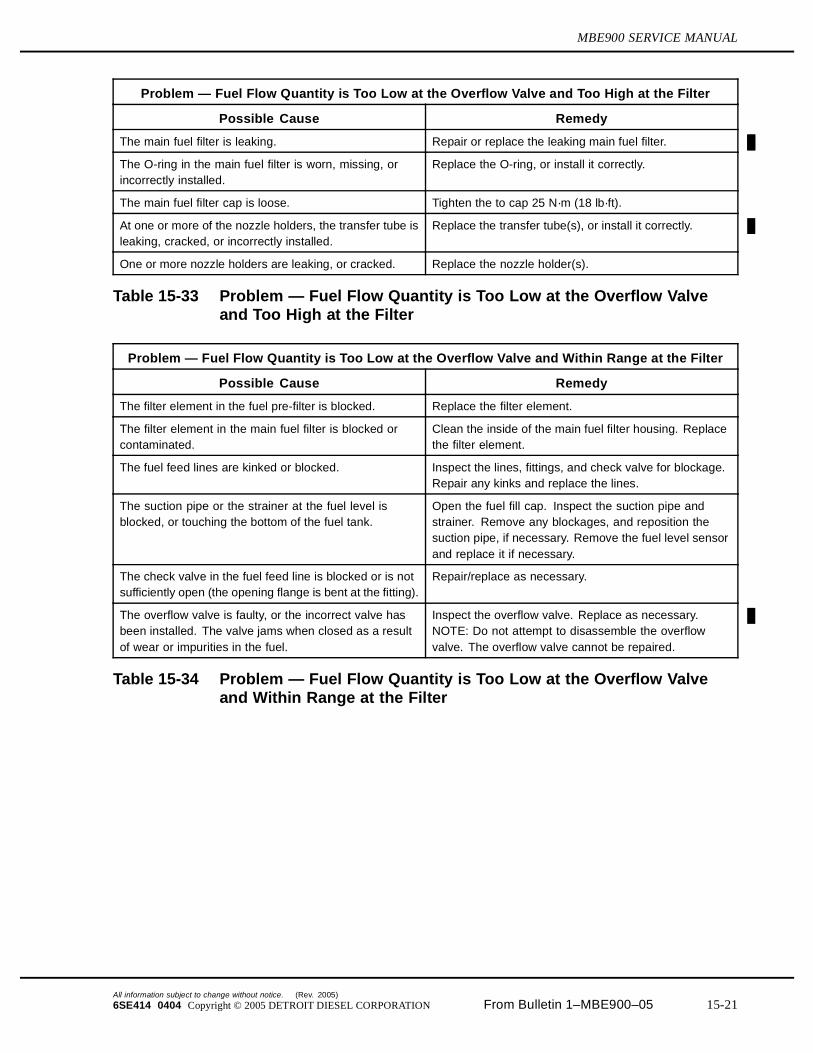
Problem — Fuel Flow Quantity is Too Low at the Overflow Valve and Too High at the Filter
Possible Cause Remedy
The main fuel filter is leaking. Repair or replace the leaking main fuel filter.
The O-ring in the main fuel filter is worn, missing, orincorrectly installed.
Replace the O-ring, or install it correctly.
The main fuel filter cap is loose. Tighten the to cap 25 N·m (18 lb·ft).
At one or more of the nozzle holders, the transfer tube isleaking, cracked, or incorrectly installed.
Replace the transfer tube(s), or install it correctly.
One or more nozzle holders are leaking, or cracked. Replace the nozzle holder(s).
Table 15-33 Problem — Fuel Flow Quantity is Too Low at the Overflow Valveand Too High at the Filter
Problem — Fuel Flow Quantity is Too Low at the Overflow Valve and Within Range at the Filter
Possible Cause Remedy
The filter element in the fuel pre-filter is blocked. Replace the filter element.
The filter element in the main fuel filter is blocked orcontaminated.
Clean the inside of the main fuel filter housing. Replacethe filter element.
The fuel feed lines are kinked or blocked. Inspect the lines, fittings, and check valve for blockage.Repair any kinks and replace the lines.
The suction pipe or the strainer at the fuel level isblocked, or touching the bottom of the fuel tank.
Open the fuel fill cap. Inspect the suction pipe andstrainer. Remove any blockages, and reposition thesuction pipe, if necessary. Remove the fuel level sensorand replace it if necessary.
The check valve in the fuel feed line is blocked or is notsufficiently open (the opening flange is bent at the fitting).
Repair/replace as necessary.
The overflow valve is faulty, or the incorrect valve hasbeen installed. The valve jams when closed as a resultof wear or impurities in the fuel.
Inspect the overflow valve. Replace as necessary.NOTE: Do not attempt to disassemble the overflowvalve. The overflow valve cannot be repaired.
Table 15-34 Problem — Fuel Flow Quantity is Too Low at the Overflow Valveand Within Range at the Filter
All information subject to change without notice. (Rev. 2005)
6SE414 0404 Copyright © 2005 DETROIT DIESEL CORPORATION From Bulletin 1–MBE900–05 15-21
15.2 GENERAL TROUBLESHOOTING
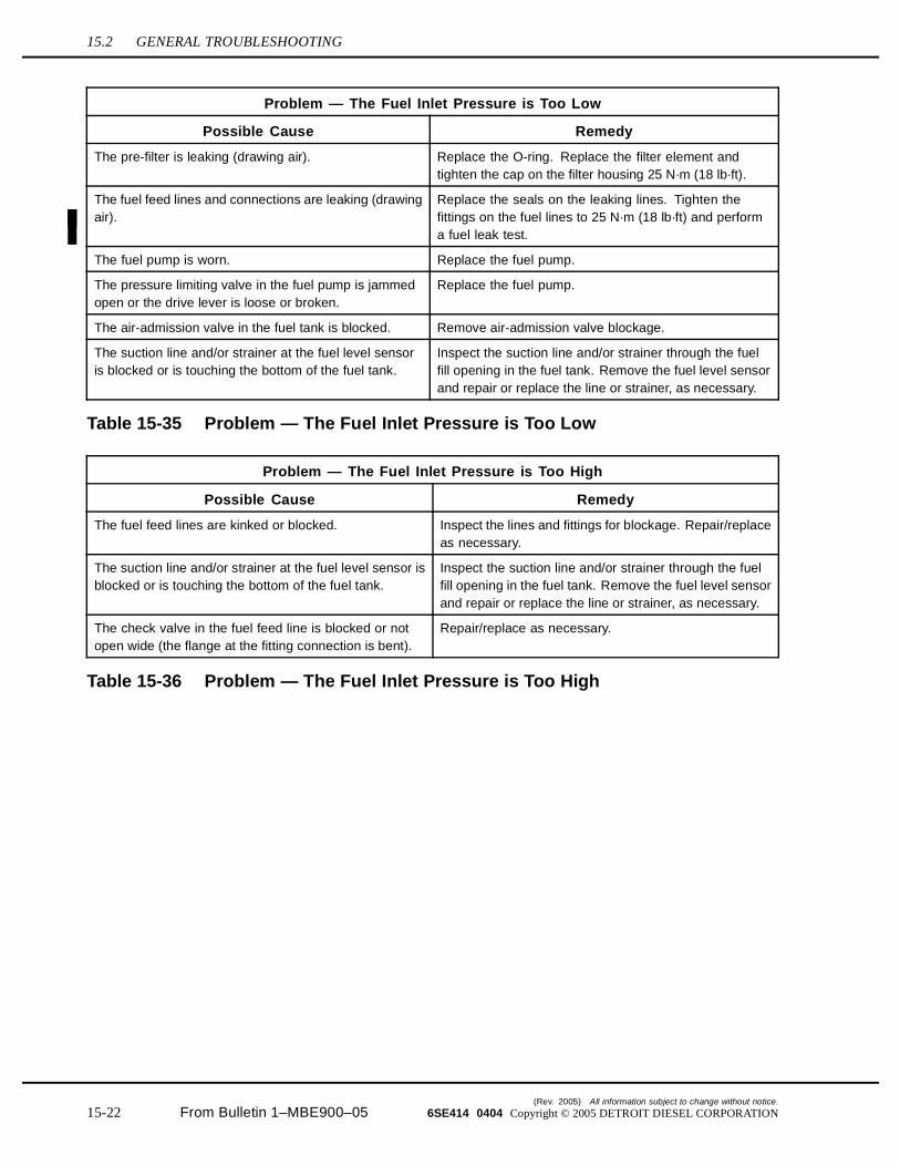
Problem — The Fuel Inlet Pressure is Too Low
Possible Cause Remedy
The pre-filter is leaking (drawing air). Replace the O-ring. Replace the filter element andtighten the cap on the filter housing 25 N·m (18 lb·ft).
The fuel feed lines and connections are leaking (drawingair).
Replace the seals on the leaking lines. Tighten thefittings on the fuel lines to 25 N·m (18 lb·ft) and performa fuel leak test.
The fuel pump is worn. Replace the fuel pump.
The pressure limiting valve in the fuel pump is jammedopen or the drive lever is loose or broken.
Replace the fuel pump.
The air-admission valve in the fuel tank is blocked. Remove air-admission valve blockage.
The suction line and/or strainer at the fuel level sensoris blocked or is touching the bottom of the fuel tank.
Inspect the suction line and/or strainer through the fuelfill opening in the fuel tank. Remove the fuel level sensorand repair or replace the line or strainer, as necessary.
Table 15-35 Problem — The Fuel Inlet Pressure is Too Low
Problem — The Fuel Inlet Pressure is Too High
Possible Cause Remedy
The fuel feed lines are kinked or blocked. Inspect the lines and fittings for blockage. Repair/replaceas necessary.
The suction line and/or strainer at the fuel level sensor isblocked or is touching the bottom of the fuel tank.
Inspect the suction line and/or strainer through the fuelfill opening in the fuel tank. Remove the fuel level sensorand repair or replace the line or strainer, as necessary.
The check valve in the fuel feed line is blocked or notopen wide (the flange at the fitting connection is bent).
Repair/replace as necessary.
Table 15-36 Problem — The Fuel Inlet Pressure is Too High
(Rev. 2005) All information subject to change without notice.
15-22 From Bulletin 1–MBE900–05 6SE414 0404 Copyright © 2005 DETROIT DIESEL CORPORATION
MBE900 SERVICE MANUAL
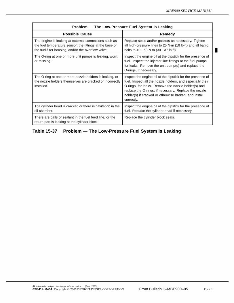
Problem — The Low-Pressure Fuel System is Leaking
Possible Cause Remedy
The engine is leaking at external connections such asthe fuel temperature sensor, the fittings at the base ofthe fuel filter housing, and/or the overflow valve.
Replace seals and/or gaskets as necessary. Tightenall high-pressure lines to 25 N·m (18 lb·ft) and all banjobolts to 40 - 50 N·m (30 - 37 lb·ft).
The O-ring at one or more unit pumps is leaking, worn,or missing.
Inspect the engine oil at the dipstick for the presence offuel. Inspect the injector line fittings at the fuel pumpsfor leaks. Remove the unit pump(s) and replace theO-rings, if necessary.
The O-ring at one or more nozzle holders is leaking, orthe nozzle holders themselves are cracked or incorrectlyinstalled.
Inspect the engine oil at the dipstick for the presence offuel. Inspect all the nozzle holders, and especially theirO-rings, for leaks. Remove the nozzle holder(s) andreplace the O-rings, if necessary. Replace the nozzleholder(s) if cracked or otherwise broken, and installcorrectly.
The cylinder head is cracked or there is cavitation in theoil chamber.
Inspect the engine oil at the dipstick for the presence offuel. Replace the cylinder head if necessary.
There are balls of sealant in the fuel feed line, or thereturn port is leaking at the cylinder block.
Replace the cylinder block seals.
Table 15-37 Problem — The Low-Pressure Fuel System is Leaking
All information subject to change without notice. (Rev. 2005)
6SE414 0404 Copyright © 2005 DETROIT DIESEL CORPORATION From Bulletin 1–MBE900–05 15-23
15.3 FUEL INJECTION TROUBLESHOOTING
15.3 FUEL INJECTION TROUBLESHOOTING
There are five fuel injection system tests which measure fuel delivery performance of the MBE900 engine. Perform the following tests and make corrections or use the troubleshooting tables:
Test #1: Downstream Pressure Test Test #2: Flow Test – At Nozzle Holder Test #3: Flow Test – At Fuel Filter Test #4: Upstream Pressure Test Test #5: Leak Test
15.3.1 General Fuel System Information and Troubleshooting
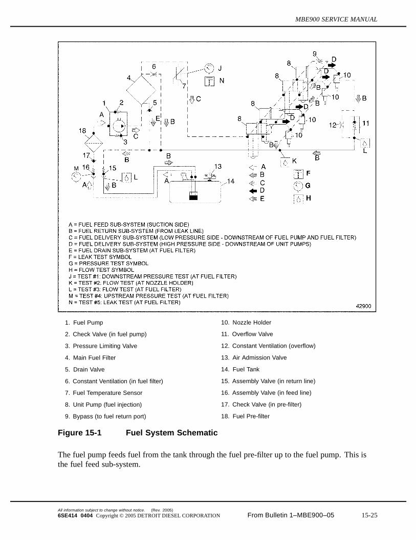
The fuel system contains five sub-systems. See Figure 15-1. The five sub-systems are:
Fuel feed Fuel return Fuel delivery, low pressure side Fuel delivery, high pressure side Fuel drain
(Rev. 2005) All information subject to change without notice.
15-24 From Bulletin 1–MBE900–05 6SE414 0404 Copyright © 2005 DETROIT DIESEL CORPORATION
MBE900 SERVICE MANUAL
1. Fuel Pump 10. Nozzle Holder
2. Check Valve (in fuel pump) 11. Overflow Valve
3. Pressure Limiting Valve 12. Constant Ventilation (overflow)
4. Main Fuel Filter 13. Air Admission Valve
5. Drain Valve 14. Fuel Tank
6. Constant Ventilation (in fuel filter) 15. Assembly Valve (in return line)
7. Fuel Temperature Sensor 16. Assembly Valve (in feed line)
8. Unit Pump (fuel injection) 17. Check Valve (in pre-filter)
9. Bypass (to fuel return port) 18. Fuel Pre-filter
Figure 15-1 Fuel System Schematic
The fuel pump feeds fuel from the tank through the fuel pre-filter up to the fuel pump. This isthe fuel feed sub-system.
All information subject to change without notice. (Rev. 2005)
6SE414 0404 Copyright © 2005 DETROIT DIESEL CORPORATION From Bulletin 1–MBE900–05 15-25
15.3 FUEL INJECTION TROUBLESHOOTING
The fuel pump delivers fuel at low pressure to the main fuel filter, and from there to the unitpumps (individual fuel injection pumps – one for each cylinder). On the way, a fuel temperaturesensor monitors the flow downstream from the filter. This is the low pressure side of the fueldelivery sub-system.
Each unit pump delivers fuel at high pressure to the fuel injectors. This is the high pressureside of the fuel delivery sub-system.
Excess fuel enters the return sub-system through a leak line. The leak line collects unused fueland empties through an overflow valve. The return lines bring the fuel back to the fuel tank.This is the fuel return sub-system.
Fuel caught in the fuel filter drains bank to the return line. This is the fuel drain sub-system.
15.3.1.1 Principles of Operation
The fuel pump controls the delivery of fuel from the fuel tank to the unit pumps. Fuel pressuredownstream of the fuel filter ranges from 400 to 650 kPa (58 to 94 psi). The fuel pump has apressure limiting valve to prevent fuel pressure from getting too high (920 kPa [133 psi]) and acheck valve to prevent pressure from getting too low (20 kPa [3 psi]). See Figure 15-2.
(Rev. 2005) All information subject to change without notice.
15-26 From Bulletin 1–MBE900–05 6SE414 0404 Copyright © 2005 DETROIT DIESEL CORPORATION
MBE900 SERVICE MANUAL
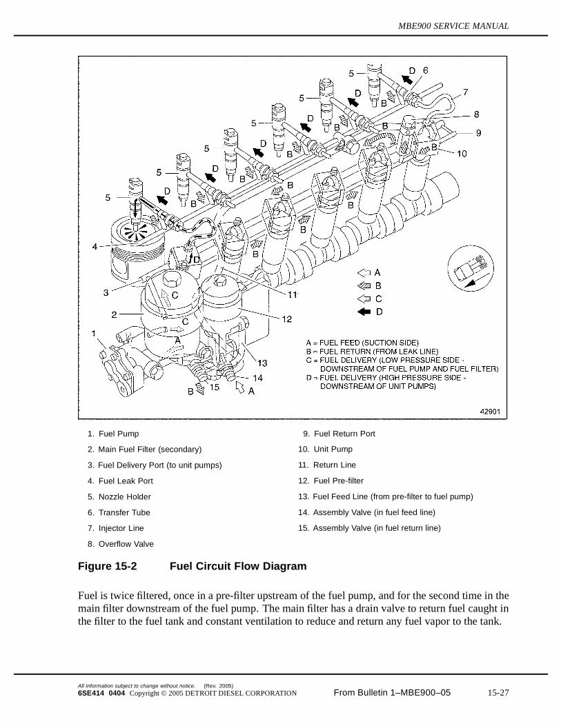
1. Fuel Pump 9. Fuel Return Port
2. Main Fuel Filter (secondary) 10. Unit Pump
3. Fuel Delivery Port (to unit pumps) 11. Return Line
4. Fuel Leak Port 12. Fuel Pre-filter
5. Nozzle Holder 13. Fuel Feed Line (from pre-filter to fuel pump)
6. Transfer Tube 14. Assembly Valve (in fuel feed line)
7. Injector Line 15. Assembly Valve (in fuel return line)
8. Overflow Valve
Figure 15-2 Fuel Circuit Flow Diagram
Fuel is twice filtered, once in a pre-filter upstream of the fuel pump, and for the second time in themain filter downstream of the fuel pump. The main filter has a drain valve to return fuel caught inthe filter to the fuel tank and constant ventilation to reduce and return any fuel vapor to the tank.
All information subject to change without notice. (Rev. 2005)
6SE414 0404 Copyright © 2005 DETROIT DIESEL CORPORATION From Bulletin 1–MBE900–05 15-27
15.3 FUEL INJECTION TROUBLESHOOTING
Unit pumps, one for each cylinder, boost minimum fuel pressure to 24,500 kPa (3,553 psi) forpurposes of injection. The fuel passes through a high-pressure line, a high-pressure connectorinserted into the wall of the cylinder head, and finally into the nozzle holder, where it is injectedinto a specially-designed swirl cup in the head of the piston.
Software maps in the DDEC-ECU regulate the timing and amount of fuel injected. Both fuelconsumption and horsepower can be changed by downloading different software mapping.
Unused fuel is not wasted. It runs off into a leak line which is controlled by a 450 kPa (65 psi)overflow valve and returned to the fuel tank. The overflow valve is also equipped with constantventilation to reduce and return fuel vapor.
15.3.1.2 Troubleshooting Tests
Perform the following troubleshooting tests on the engine:
1. Run the engine for two to three minutes at rated speed, 2500 rpm.
NOTICE:
Correct torque on the high pressure lines is critical. Incorrecttorques could result in leaks or lack of power due to restrictedfuel flow.
2. Perform a visual inspection of all fuel lines, pressure fittings, and components, includingall the fittings that connect the fuel feed and drain hoses to the fuel filter housing. Replaceany components found to be damaged or leaking. If necessary, tighten all high-pressurefittings to 25 N·m (18 lb·ft) and all banjo bolts to 40-50 N·m (30-37 lb·ft).
3. Inspect the filter element in the fuel pre-filter. Replace if necessary.
4. Inspect the filter element in the main fuel filter. Replace if necessary.
5. On engines with speed governors, connect minidiag2 to the vehicle and increase theengine speed to 4000 rpm. Note the governed engine speed given.
6. Continue to run the engine until it reaches the operating temperature of approximately82°C (180°F). When the operating temperature has been reached, shut the engine downand go to the next step.
NOTE:When doing these tests, be sure the temperature of the fuel in the fuel tank is no higherthan 40°C (104°F). Collect any fuel which flows out during the test. The fuel should flowthrough free of bubbles.
7. Perform the fuel system troubleshooting tests and correct any problems. As indicated bythe test results, perform any follow-up tests or check troubleshooting tables, as required.Make the necessary repairs and/or replacements. For troubleshooting tests and tablessee the following subjects:
[a] Test #1: Downstream Pressure Test. Refer to section 15.3.2.
(Rev. 2005) All information subject to change without notice.
15-28 From Bulletin 1–MBE900–05 6SE414 0404 Copyright © 2005 DETROIT DIESEL CORPORATION
MBE900 SERVICE MANUAL
[b] Test #2: Flow Test – At Nozzle Holder. Refer to section 15.3.3.
[c] Test #3: Flow Test – At Fuel Filter. Refer to section 15.3.4.
[d] Test #4: Upstream Pressure Test. Refer to section 15.3.5.
[e] Test #5: Leak Test. Refer to section 15.3.6.
[f] Troubleshooting tables.
8. When all the tests are completed, the test equipment removed, and all repairs/replacementshave been made, prime the fuel system.
[a] If equipped with a hand pump on the fuel/water separator, work the hand pumpuntil resistance is felt.
PERSONAL INJURY
To avoid injury before starting and running the engine,ensure the vehicle is parked on a level surface, parkingbrake is set, and the wheels are blocked.
[b] Crank the engine for 30 seconds at a time, but no longer. Before cranking the engineagain, wait at least two minutes. The engine should start within four 30-secondattempts. The fuel system is bled automatically.
9. If the problem has still not been resolved, test vehicle performance on a chassisdynamometer. If there is no improvement in fuel consumption or performance, connect afuel consumption measuring system.
15.3.2 Test #1: Downstream Pressure Test
Perform the following test set-up and test to determine the downstream pressure.
All information subject to change without notice. (Rev. 2005)
6SE414 0404 Copyright © 2005 DETROIT DIESEL CORPORATION From Bulletin 1–MBE900–05 15-29

15.3 FUEL INJECTION TROUBLESHOOTING
15.3.2.1 Test Set-Up
1. Remove the engine trim panel. See Figure 15-3.
1. Engine Trim Panel 3. Fuel Temperature Sensor
2. Engine Wiring Harness
Figure 15-3 Test Setup #1: Downstream Pressure Test
(Rev. 2005) All information subject to change without notice.
15-30 From Bulletin 1–MBE900–05 6SE414 0404 Copyright © 2005 DETROIT DIESEL CORPORATION
MBE900 SERVICE MANUAL
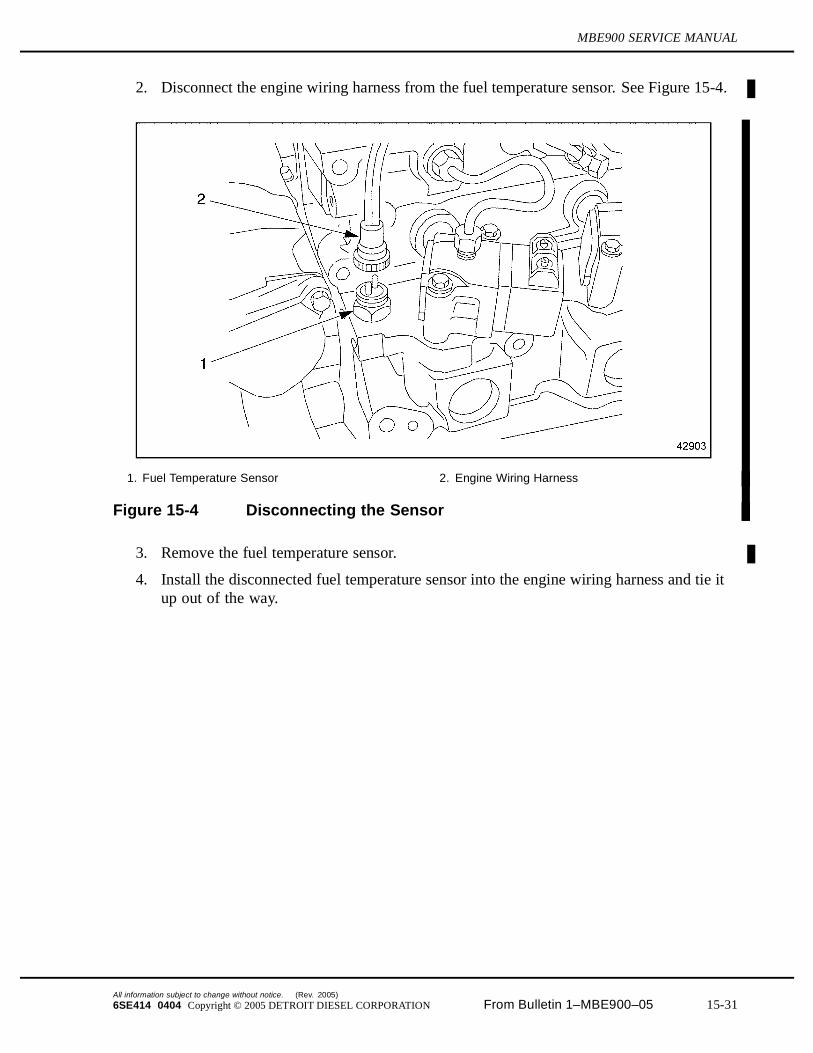
2. Disconnect the engine wiring harness from the fuel temperature sensor. See Figure 15-4.
1. Fuel Temperature Sensor 2. Engine Wiring Harness
Figure 15-4 Disconnecting the Sensor
3. Remove the fuel temperature sensor.
4. Install the disconnected fuel temperature sensor into the engine wiring harness and tie itup out of the way.
All information subject to change without notice. (Rev. 2005)
6SE414 0404 Copyright © 2005 DETROIT DIESEL CORPORATION From Bulletin 1–MBE900–05 15-31
15.3 FUEL INJECTION TROUBLESHOOTING
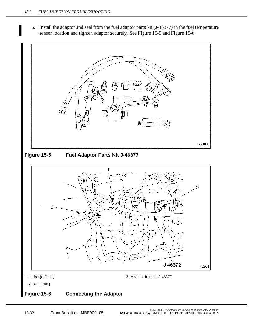
5. Install the adaptor and seal from the fuel adaptor parts kit (J-46377) in the fuel temperaturesensor location and tighten adaptor securely. See Figure 15-5 and Figure 15-6.
Figure 15-5 Fuel Adaptor Parts Kit J-46377
1. Banjo Fitting 3. Adaptor from kit J-46377
2. Unit Pump
Figure 15-6 Connecting the Adaptor
(Rev. 2005) All information subject to change without notice.
15-32 From Bulletin 1–MBE900–05 6SE414 0404 Copyright © 2005 DETROIT DIESEL CORPORATION
MBE900 SERVICE MANUAL
6. Attach the banjo fitting and banjo bolt union from the fuel adaptor kit (J-46377) to theadaptor.
7. Connect the high-pressure fuel line (J-46372) and gauge (J-46378) to the adaptor.
15.3.2.2 Test #1
1. Open the fuel fill cap to release pressure in the fuel tank.
PERSONAL INJURY
To avoid injury before starting and running the engine,ensure the vehicle is parked on a level surface, parkingbrake is set, and the wheels are blocked.
2. Start the engine and run it at a slow idle, 600 to 650 rpm.
3. Read off the fuel pressure on the high-pressure gauge. The gauge should read at least430 kPa (62 psi). If the fuel pressure is too low, perform test #3: Flow Test—At FuelFilter, and correct the problem. Refer to section 15.3.4.
4. Increase the engine speed to 2500 rpm.
5. Read off the fuel pressure on the high-pressure gauge. The gauge should read from 400 to650 kPa (58 to 94 psi).
[a] If the fuel pressure is within limits, perform test #2: Flow Test—At Nozzle Holder,and correct the problem. Refer to section 15.3.3.
[b] If the fuel pressure is too low, perform test #3: Flow Test—At Fuel Filter, and correctthe problem. Refer to section 15.3.4.
[c] If the fuel pressure is too high, see the causes listed in Table 15-31, “Problem — TheFuel Pressure is Too High Downstream of the Fuel Filter,” and correct the problem.Make any necessary repairs and/or replacements.
6. Remove all test equipment. Reconnect the fuel temperature sensor.
7. Make sure the fuel fill cap is tightly closed and the vehicle has been restored to operatingcondition.
15.3.3 Test #2: Flow Test — At Nozzle Holder
Perform the following test set-up and test to determine the flow at the nozzle holder:
All information subject to change without notice. (Rev. 2005)
6SE414 0404 Copyright © 2005 DETROIT DIESEL CORPORATION From Bulletin 1–MBE900–05 15-33
15.3 FUEL INJECTION TROUBLESHOOTING
15.3.3.1 Test Set-Up
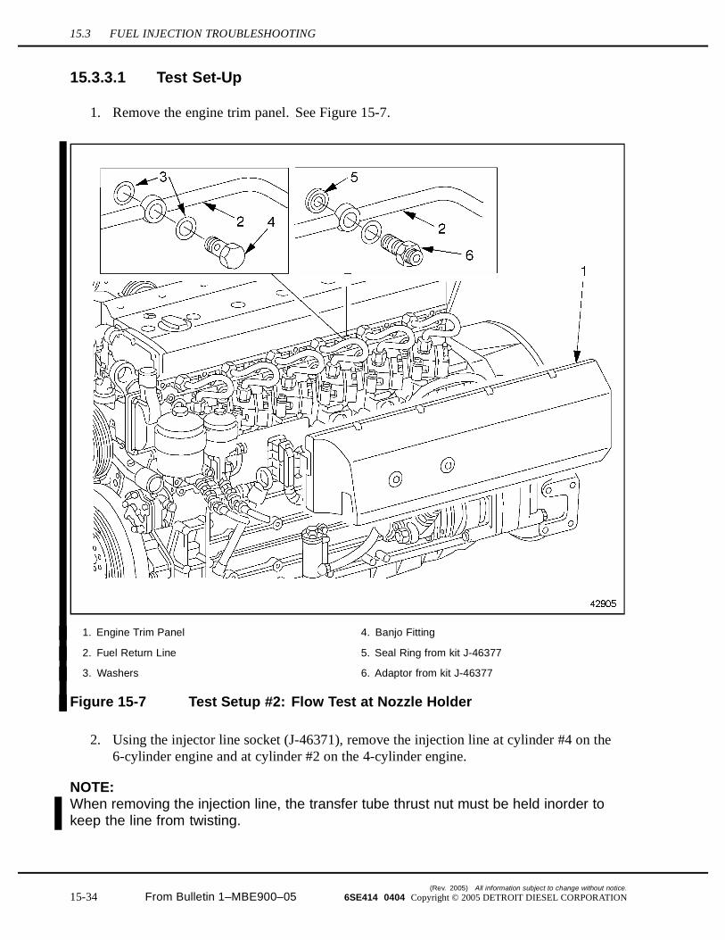
1. Remove the engine trim panel. See Figure 15-7.
1. Engine Trim Panel 4. Banjo Fitting
2. Fuel Return Line 5. Seal Ring from kit J-46377
3. Washers 6. Adaptor from kit J-46377
Figure 15-7 Test Setup #2: Flow Test at Nozzle Holder
2. Using the injector line socket (J-46371), remove the injection line at cylinder #4 on the6-cylinder engine and at cylinder #2 on the 4-cylinder engine.
NOTE:When removing the injection line, the transfer tube thrust nut must be held inorder tokeep the line from twisting.
(Rev. 2005) All information subject to change without notice.
15-34 From Bulletin 1–MBE900–05 6SE414 0404 Copyright © 2005 DETROIT DIESEL CORPORATION

MBE900 SERVICE MANUAL
3. Remove the fuel return line, banjo fitting and washers from the cylinder head at the samecylinder from which the injection line was removed.
4. Using the adaptor and seal rings from the fuel adaptor parts kit (J-46377) to install the fuelreturn line back onto the cylinder head. Tighten adaptor securely.
5. Install the injection line using the injector line socket (J-46371). Torque injection line to25 N·m (18 lb·ft).
6. Place a clean cloth below the opening in the adaptor to catch any fuel which leaks outof the return line during the test.
15.3.3.2 Test #2
1. Open the fuel fill cap to release pressure in the fuel tank.
PERSONAL INJURY
To avoid injury before starting and running the engine,ensure the vehicle is parked on a level surface, parkingbrake is set, and the wheels are blocked.
2. Start the engine and run it at a slow idle, 600 to 650 rpm until the adaptor opening appearsmoist. If fuel or coolant flows out of the return line, see the causes listed in Table 15-32,“Problem — Fuel Flows Out of the Fuel Return Line,” and correct the problem. Makeany necessary repairs and/or replacements.
3. Increase the engine speed to 2500 rpm. At most, drops of fuel should appear at the adaptoropening. If fuel or coolant flows out of the return line, see the causes listed in Table 15-32,“Problem — Fuel Flows Out of the Fuel Return Line,” and correct the problem. Makeany necessary repairs and/or replacements.
4. Remove the adaptor and seal ring part of kit (J-46377). Restore the fuel return line to theoriginal installation, as removed. Tighten banjo bolt to 40-50 N·m (30-37 lb·ft).
5. Make sure the fuel fill cap is tightly closed and the vehicle has been restored to operatingcondition.
15.3.4 Test #3: Flow Test — At Fuel Filter
Perform the following test set-up and test to determine the flow at the fuel filter.
All information subject to change without notice. (Rev. 2005)
6SE414 0404 Copyright © 2005 DETROIT DIESEL CORPORATION From Bulletin 1–MBE900–05 15-35
15.3 FUEL INJECTION TROUBLESHOOTING
15.3.4.1 Test Set-Up
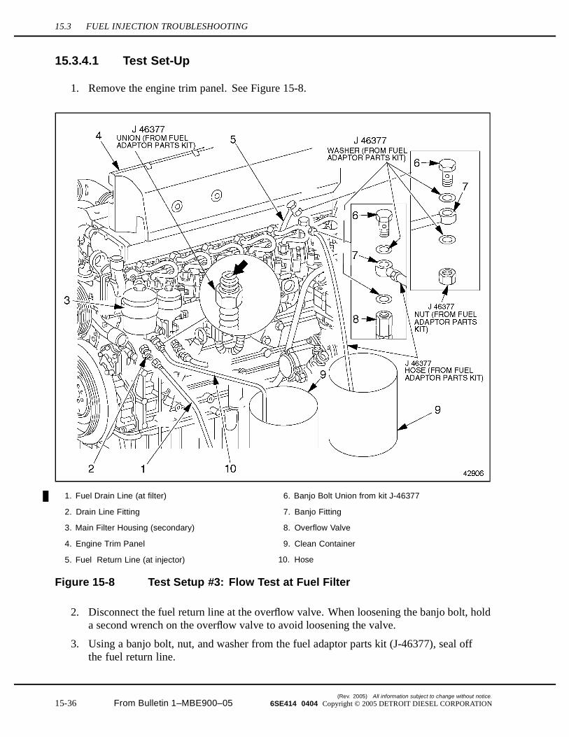
1. Remove the engine trim panel. See Figure 15-8.
1. Fuel Drain Line (at filter) 6. Banjo Bolt Union from kit J-46377
2. Drain Line Fitting 7. Banjo Fitting
3. Main Filter Housing (secondary) 8. Overflow Valve
4. Engine Trim Panel 9. Clean Container
5. Fuel Return Line (at injector) 10. Hose
Figure 15-8 Test Setup #3: Flow Test at Fuel Filter
2. Disconnect the fuel return line at the overflow valve. When loosening the banjo bolt, holda second wrench on the overflow valve to avoid loosening the valve.
3. Using a banjo bolt, nut, and washer from the fuel adaptor parts kit (J-46377), seal offthe fuel return line.
(Rev. 2005) All information subject to change without notice.
15-36 From Bulletin 1–MBE900–05 6SE414 0404 Copyright © 2005 DETROIT DIESEL CORPORATION

MBE900 SERVICE MANUAL
4. In place of the fuel return line, attach the hose with a banjo fitting from the fuel adaptorparts kit (J-46377) to the overflow valve. When tightening the union, hold a secondwrench on the overflow valve to avoid over-tightening the valve.
5. At the main fuel filter, detach the fuel drain line and its fitting from the main filter housing.
6. In place of the fuel drain line, attach a union from the fuel adaptor parts kit to the mainfilter housing.
7. At the union, attach a hose and run the other end of the hose into another clean container.
15.3.4.2 Test #3
1. Open the fuel fill cap to release pressure in the fuel tank.
PERSONAL INJURY
To avoid injury before starting and running the engine,ensure the vehicle is parked on a level surface, parkingbrake is set, and the wheels are blocked.
2. Start the engine and run it at a slow idle, 600 to 650 rpm, until the fuel flows into thecontainer with little or no bubbling.
3. Check the fuel flow at the fuel filter.
NOTE:When beginning the timed portion of this test, take the transparent hose out of the cleancontainer and insert it into a calibrated container or measuring cup.
[a] Measure the quantity of fuel that flows out of the hose in one minute (60 seconds). Ifmore than 300 mL (10.1 oz.) flow out, fuel flow at the filter is too high (at idle).
[b] Increase the engine speed to 2500 rpm.
[c] Measure the quantity of fuel that flows out of the hose in one minute. If more than300 mL (10.1 oz.) flow out, fuel flow at the filter is too high (at rated speed).
NOTE:If fuel flow on either test is too high, correct the problem. Fuel flow is OK if the systempasses both tests.
4. Check the fuel flow at the overflow valve.
[a] Reduce engine speed back to slow idle, 600 to 650 rpm.
NOTE:When beginning the timed portion of this test, take the transparent hose out of the cleancontainer and insert it into a large calibrated container.
All information subject to change without notice. (Rev. 2005)
6SE414 0404 Copyright © 2005 DETROIT DIESEL CORPORATION From Bulletin 1–MBE900–05 15-37
15.3 FUEL INJECTION TROUBLESHOOTING
[b] Measure the quantity of fuel that flows out of the hose in one minute (60 seconds). Ifmore than 1.7 Liter (1.8 qt) flows out, overflow valve fuel flow is too high. If lessthan 0.9 Liter (0.95 qt) flows out, overflow valve fuel flow is too low.
If between 0.9 Liter (0.95 qt) and 1.7 Liter (1.8 qt) flows out, overflow valve fuelflow is within range.
[c] Increase the engine speed to 2500 rpm.
[d] Measure the quantity of fuel that flows out of the hose in one minute. If more than7.5 Liter (7.9 qt) flows out, overflow fuel flow is too high. If less than 2.7 Liter (2.9qt) flows out, overflow fuel flow is too low.
If between 2.7 Liter (2.9 qt) and 7.5 Liter (7.9 qt) flows out, overflow fuel flow iswithin range.
5. If overflow valve fuel flow is too low and filter fuel flow is too high, see thecauses listed in Table 15-33, “Problem – Fuel Flow Quantity is Too Low at the OverflowValve and Too High at the Filter,” and correct the problem. Make any necessary repairsand/or replacements. If overflow valve fuel flow is too low and fuel flow is OK at thefilter, see the causes listed in Table 15-34, “Problem — Fuel Flow Quantity is Too Lowat the Overflow Valve and Within Range at the Filter,” and correct the problem. Makeany necessary repairs and/or replacements.
If overflow valve fuel flow is too low and fuel flow is also too low at the filter, performtest #4: Upstream Pressure Test. Refer to section 15.3.5.
If overflow valve fuel flow is OK and no fuel flows out at the filter, the continuousventilation port in the fuel filter is blocked by impurities. Open the fuel filter and clean orreplace the blocked port.
If overflow valve fuel flow is OK and fuel flow is also OK at the filter, the overflow valveis faulty, leaking, jammed open, worn, or incorrectly installed. Replace the overflowvalve. Refer to section 15.13.5.
NOTE:Do not attempt to disassemble the overflow valve. The overflow valve cannot be repaired.
6. Remove the union, transparent hose, banjo bolt, and nut. Restore the fuel return and drainlines to the original installation, as removed.
7. Make sure the fuel fill cap is tightly closed and the vehicle has been restored to operatingcondition.
15.3.5 Test #4: Upstream Pressure Test
Perform the following test set-up and test to determine the upstream pressure.
(Rev. 2005) All information subject to change without notice.
15-38 From Bulletin 1–MBE900–05 6SE414 0404 Copyright © 2005 DETROIT DIESEL CORPORATION
MBE900 SERVICE MANUAL
15.3.5.1 Test Set-Up
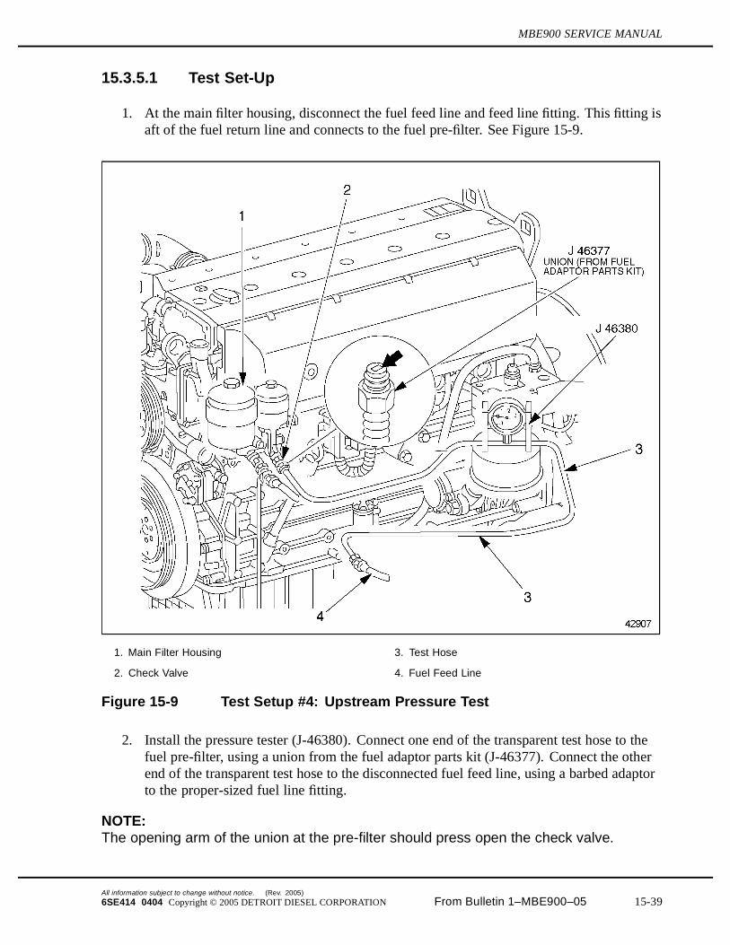
1. At the main filter housing, disconnect the fuel feed line and feed line fitting. This fitting isaft of the fuel return line and connects to the fuel pre-filter. See Figure 15-9.
1. Main Filter Housing 3. Test Hose
2. Check Valve 4. Fuel Feed Line
Figure 15-9 Test Setup #4: Upstream Pressure Test
2. Install the pressure tester (J-46380). Connect one end of the transparent test hose to thefuel pre-filter, using a union from the fuel adaptor parts kit (J-46377). Connect the otherend of the transparent test hose to the disconnected fuel feed line, using a barbed adaptorto the proper-sized fuel line fitting.
NOTE:The opening arm of the union at the pre-filter should press open the check valve.
All information subject to change without notice. (Rev. 2005)
6SE414 0404 Copyright © 2005 DETROIT DIESEL CORPORATION From Bulletin 1–MBE900–05 15-39
15.3 FUEL INJECTION TROUBLESHOOTING
3. Inspect the seals at the fitting on the fuel pre-filter for damage and replace if necessary.
4. Prime the fuel system.
[a] If equipped with a hand pump on the fuel/water separator, work the hand pumpuntil resistance is felt.
PERSONAL INJURY
To avoid injury before starting and running the engine,ensure the vehicle is parked on a level surface, parkingbrake is set, and the wheels are blocked.
[b] Crank the engine for 30 seconds at a time, but no longer. Before cranking the engineagain, wait at least two minutes. The engine should start within four 30-secondattempts. The fuel system is bled automatically.
5. Stand the pressure tester on a level spot, such as the frame rail.
NOTE:The pressure tester must be level to indicate correctly.
15.3.5.2 Test #4
1. Open the fuel fill cap to release pressure in the fuel tank.
PERSONAL INJURY
To avoid injury before starting and running the engine,ensure the vehicle is parked on a level surface, parkingbrake is set, and the wheels are blocked.
2. Start the engine and run it at a slow idle, 600 to 650 rpm.
NOTE:The pressure tester reads in bar. 1 bar = 14.5 psi or 100 kPa.
NOTE:This test measures suction at the fuel inlet. All pressure values are negative.
3. Read off the fuel pressure on the pressure tester. The gauge should read from –0.09 bar to–0.12 bar (–1.3 to –1.7 psi [–9 to –12 kPa]). If the fuel pressure is too low (less suction),see the causes listed in Table 15-35, “Problem — The Inlet Pressure is Too Low,” andcorrect the problem. Make any necessary repairs and/or replacements.
(Rev. 2005) All information subject to change without notice.
15-40 From Bulletin 1–MBE900–05 6SE414 0404 Copyright © 2005 DETROIT DIESEL CORPORATION
MBE900 SERVICE MANUAL
If the fuel pressure is too high (more suction), see the causes listed in Table 15-36,“Problem — The Inlet Pressure is Too High,” and correct the problem. Make anynecessary repairs and/or replacements.
4. Increase the engine speed to 2500 rpm.
5. Read off the fuel pressure on the pressure tester. The gauge should read between –0.4 and–0.5 bar (–5.8 to –7.3 psi [–40 to –50 kPa]). If the fuel pressure is too low (less suction),see the causes listed in Table 15-35, “Problem — The Inlet Pressure is Too Low,” andcorrect the problem. Make any necessary repairs and/or replacements.
If the fuel pressure is too high (more suction), see the causes listed in Table 15-36,“Problem — The Inlet Pressure is Too High,” and correct the problem. Make anynecessary repairs and/or replacements.
6. Remove all test equipment. Reconnect the fuel feed line.
7. Make sure the fuel fill cap is tightly closed and the vehicle has been restored to operatingcondition.
15.3.6 Test #5: Leak Test
Perform the following test set-up and test to determine if and where the fuel system is leaking.
All information subject to change without notice. (Rev. 2005)
6SE414 0404 Copyright © 2005 DETROIT DIESEL CORPORATION From Bulletin 1–MBE900–05 15-41
15.3 FUEL INJECTION TROUBLESHOOTING
15.3.6.1 Test Set-Up
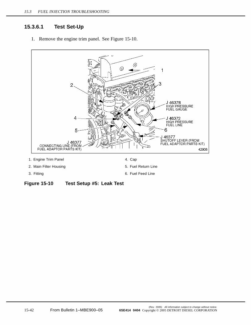
1. Remove the engine trim panel. See Figure 15-10.
1. Engine Trim Panel 4. Cap
2. Main Filter Housing 5. Fuel Return Line
3. Fitting 6. Fuel Feed Line
Figure 15-10 Test Setup #5: Leak Test
(Rev. 2005) All information subject to change without notice.
15-42 From Bulletin 1–MBE900–05 6SE414 0404 Copyright © 2005 DETROIT DIESEL CORPORATION
MBE900 SERVICE MANUAL
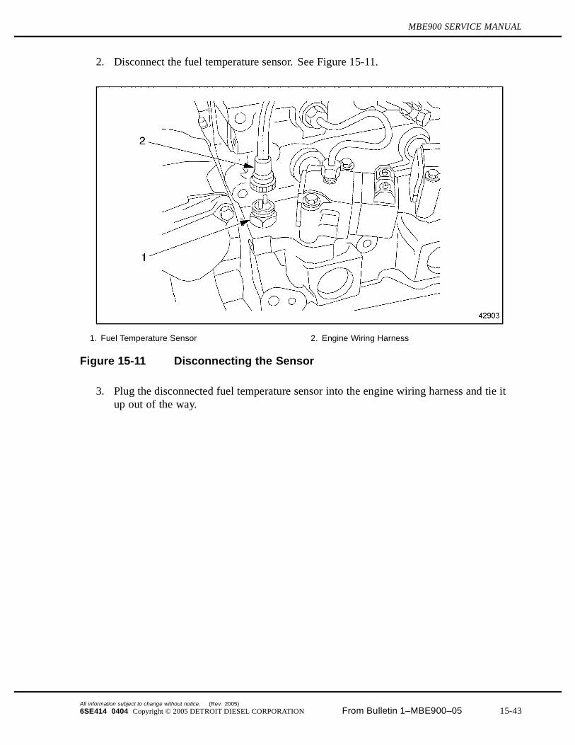
2. Disconnect the fuel temperature sensor. See Figure 15-11.
1. Fuel Temperature Sensor 2. Engine Wiring Harness
Figure 15-11 Disconnecting the Sensor
3. Plug the disconnected fuel temperature sensor into the engine wiring harness and tie itup out of the way.
All information subject to change without notice. (Rev. 2005)
6SE414 0404 Copyright © 2005 DETROIT DIESEL CORPORATION From Bulletin 1–MBE900–05 15-43
15.3 FUEL INJECTION TROUBLESHOOTING
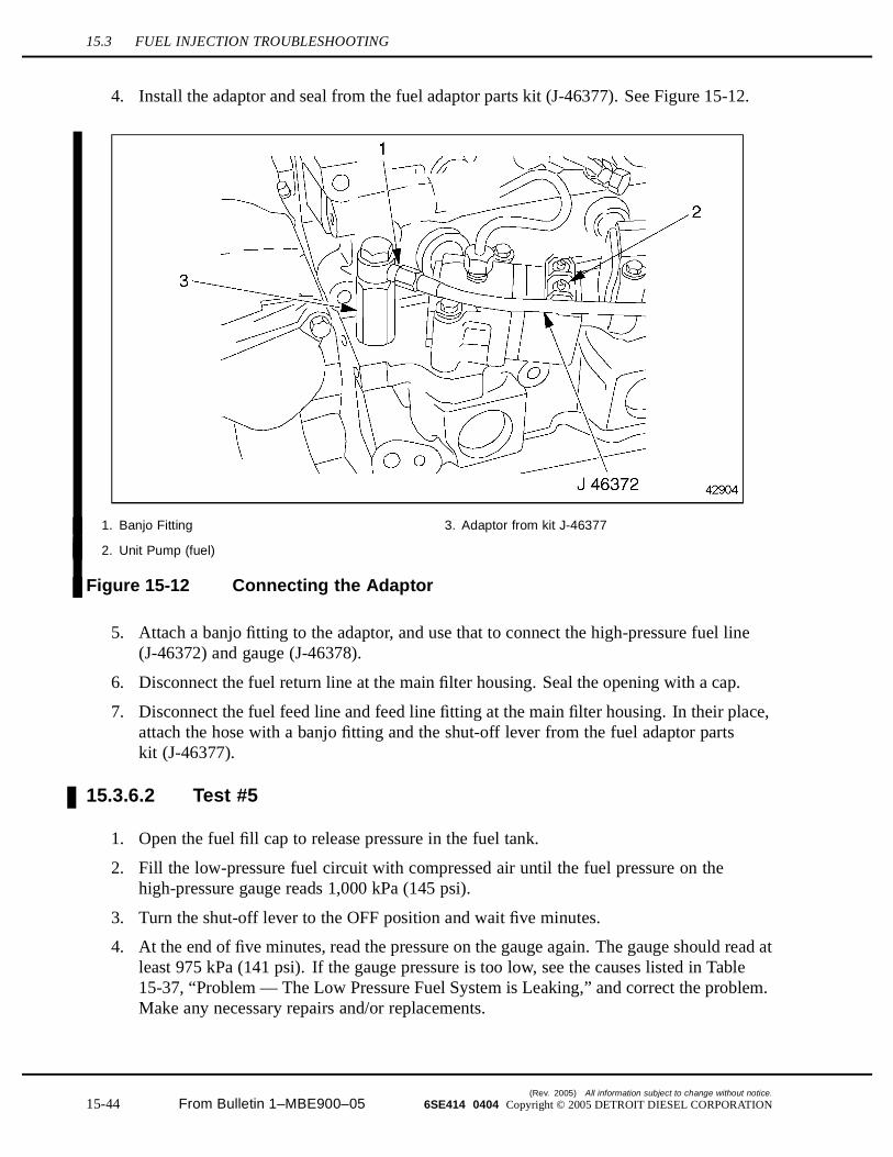
4. Install the adaptor and seal from the fuel adaptor parts kit (J-46377). See Figure 15-12.
1. Banjo Fitting 3. Adaptor from kit J-46377
2. Unit Pump (fuel)
Figure 15-12 Connecting the Adaptor
5. Attach a banjo fitting to the adaptor, and use that to connect the high-pressure fuel line(J-46372) and gauge (J-46378).
6. Disconnect the fuel return line at the main filter housing. Seal the opening with a cap.
7. Disconnect the fuel feed line and feed line fitting at the main filter housing. In their place,attach the hose with a banjo fitting and the shut-off lever from the fuel adaptor partskit (J-46377).
15.3.6.2 Test #5
1. Open the fuel fill cap to release pressure in the fuel tank.
2. Fill the low-pressure fuel circuit with compressed air until the fuel pressure on thehigh-pressure gauge reads 1,000 kPa (145 psi).
3. Turn the shut-off lever to the OFF position and wait five minutes.
4. At the end of five minutes, read the pressure on the gauge again. The gauge should read atleast 975 kPa (141 psi). If the gauge pressure is too low, see the causes listed in Table15-37, “Problem — The Low Pressure Fuel System is Leaking,” and correct the problem.Make any necessary repairs and/or replacements.
(Rev. 2005) All information subject to change without notice.
15-44 From Bulletin 1–MBE900–05 6SE414 0404 Copyright © 2005 DETROIT DIESEL CORPORATION
MBE900 SERVICE MANUAL
5. Check the engine oil for presence of fuel. If there is fuel in the engine oil, see the causeslisted in Table 15-37, “Problem — The Low Pressure Fuel System is Leaking,” and correctthe problem. Make any necessary repairs and/or replacements.
6. Open the shut-off valve and remove all the test equipment. Connect the fuel feed andreturn lines, as removed. Reconnect the fuel temperature sensor.
7. Make sure the fuel fill cap is tightly closed and the vehicle has been restored to operatingcondition.
All information subject to change without notice. (Rev. 2005)
6SE414 0404 Copyright © 2005 DETROIT DIESEL CORPORATION From Bulletin 1–MBE900–05 15-45

15.4 MISFIRING CYLINDER
15.4 MISFIRING CYLINDER
There are several causes for the engine cylinder to be misfiring. These probable causes are:
Poor Vehicle Ground Aerated Fuel Improper Valve Clearance, Worn or Damaged Camshaft Lobes and Roller Followers Faulty Fuel Nozzle Faulty DDEC-ECU Worn or Damaged Valve or Cylinder Kit
15.4.1 Troubleshooting Procedure for Poor Vehicle Ground
To determine if poor vehicle ground is causing the cylinder to misfire, perform the following steps:
1. Remove the alternator belt. Refer to section 8.2.1.
PERSONAL INJURY
To avoid injury before starting and running the engine,ensure the vehicle is parked on a level surface, parkingbrake is set, and the wheels are blocked.
2. Start the engine.
3. Run the engine through operating range.
4. Listen for engine misfiring.
[a] If the engine is not misfiring, refer to section 15.4.2. Shut down the engine.
[b] If the engine is still misfiring, check for aerated fuel; refer to section 15.4.3.
15.4.2 Negative Lead Repair
Perform the following steps for negative lead repair:
1. Shut down the engine.
2. Remove negative lead(s) at frame ground stud near battery box.
3. Clean ground stud; refer to OEM guidelines.
4. Clean negative lead(s) terminal lugs with low grit sandpaper.
5. Repair any loose or damaged lead(s), using the splice method or rosin core solder.
6. Install negative lead(s) to frame ground stud; refer to OEM guidelines.
(Rev. 2005) All information subject to change without notice.
15-46 From Bulletin 1–MBE900–05 6SE414 0404 Copyright © 2005 DETROIT DIESEL CORPORATION
MBE900 SERVICE MANUAL
7. Install alternator belt. Refer to section 8.2.1.
NOTE:Drive belts (Vee and poly-vee) should be replaced every 2,000 hours or 100,000 miles(160,000 km).
8. Verify negative lead repair; refer to section 15.4.2.1.
15.4.2.1 Verification of Repair for Negative Lead
Perform the following steps to determine if negative lead repair resolved the misfiring cylindercondition:
PERSONAL INJURY
To avoid injury before starting and running the engine,ensure the vehicle is parked on a level surface, parkingbrake is set, and the wheels are blocked.
1. Start the engine.
2. Run engine speed up to the occurrence of the misfiring.
3. Listen for misfiring cylinder.
[a] If the engine is not misfiring, no further troubleshooting is required. Shut downthe engine.
[b] If the engine is misfiring, check for aerated fuel. Shut down the engine;refer to section 15.4.3.
15.4.3 Troubleshooting Procedure for Aerated Fuel
To determine if aerated fuel is causing the cylinder to misfire, perform the following steps:
1. Disconnect the fuel line return hose from the fitting located at the fuel tank.
2. Place the opened end of fuel line into a suitable container.
All information subject to change without notice. (Rev. 2005)
6SE414 0404 Copyright © 2005 DETROIT DIESEL CORPORATION From Bulletin 1–MBE900–05 15-47
15.4 MISFIRING CYLINDER
PERSONAL INJURY
To avoid injury before starting and running the engine,ensure the vehicle is parked on a level surface, parkingbrake is set, and the wheels are blocked.
3. Start the engine.
4. Run the engine at 1000 rpm.
5. Visually check to see if air bubbles are rising to the surface of the fuel within the container.
[a] If air bubbles are present, refer to section 15.4.4.
[b] If air bubbles are not present, shut down the engine. Check for improper valveclearance, and worn or damaged camshaft lobes and roller followers; refer to section15.4.5.
15.4.4 Aerated Fuel Repair
Perform the following steps to repair the air in the fuel:
1. Shut down the engine.
2. Tighten all fuel line connections between fuel tank and fuel pump; refer to OEMguidelines.
3. Visually inspect all fuel lines between fuel tank and fuel pump for leaks.
4. Replace any damaged components.
5. Verify repair of fuel lines:
[a] If no air in the fuel return, refer to section 15.4.4.1.
[b] If air in the fuel return, locate and repair. Then refer to section 15.4.4.1.
15.4.4.1 Test the Engine with Repair for Aerated Fuel
Perform the following steps to determine if the aerated fuel repair resolved the misfiring cylindercondition:
(Rev. 2005) All information subject to change without notice.
15-48 From Bulletin 1–MBE900–05 6SE414 0404 Copyright © 2005 DETROIT DIESEL CORPORATION
MBE900 SERVICE MANUAL
PERSONAL INJURY
To avoid injury before starting and running the engine,ensure the vehicle is parked on a level surface, parkingbrake is set, and the wheels are blocked.
1. Start engine.
2. Run the engine at 1000 rpm.
3. Listen for misfiring cylinder.
[a] If the engine is not misfiring, no further troubleshooting is required. Shut downthe engine.
[b] If the engine is misfiring, check for improper valve clearance, or worn or damagedcamshaft lobes or rollers. Shut down the engine; refer to section 15.4.5.
All information subject to change without notice. (Rev. 2005)
6SE414 0404 Copyright © 2005 DETROIT DIESEL CORPORATION From Bulletin 1–MBE900–05 15-49
15.4 MISFIRING CYLINDER
15.4.5 Troubleshooting Procedure for Improper Valve Clearance, Wornor Damaged Camshaft Lobes and Rollers
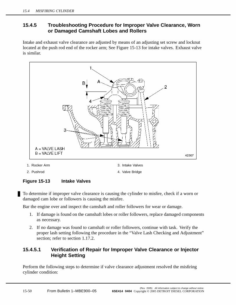
Intake and exhaust valve clearance are adjusted by means of an adjusting set screw and locknutlocated at the push rod end of the rocker arm; See Figure 15-13 for intake valves. Exhaust valveis similar.
1. Rocker Arm 3. Intake Valves
2. Pushrod 4. Valve Bridge
Figure 15-13 Intake Valves
To determine if improper valve clearance is causing the cylinder to misfire, check if a worn ordamaged cam lobe or followers is causing the misfire.
Bar the engine over and inspect the camshaft and roller followers for wear or damage.
1. If damage is found on the camshaft lobes or roller followers, replace damaged componentsas necessary.
2. If no damage was found to camshaft or roller followers, continue with task. Verify theproper lash setting following the procedure in the “Valve Lash Checking and Adjustment”section; refer to section 1.17.2.
15.4.5.1 Verification of Repair for Improper Valve Clearance or InjectorHeight Setting
Perform the following steps to determine if valve clearance adjustment resolved the misfiringcylinder condition:
(Rev. 2005) All information subject to change without notice.
15-50 From Bulletin 1–MBE900–05 6SE414 0404 Copyright © 2005 DETROIT DIESEL CORPORATION
MBE900 SERVICE MANUAL
PERSONAL INJURY
To avoid injury before starting and running the engine,ensure the vehicle is parked on a level surface, parkingbrake is set, and the wheels are blocked.
1. Start the engine.
2. Run the engine at 1000 rpm.
3. Listen for misfiring cylinder.
[a] If engine is not misfiring, shut down the engine. No further troubleshooting isrequired.
[b] If engine is misfiring, shut down the engine and check for faulty fuel nozzle;refer to section 15.4.6.
15.4.6 Troubleshooting Procedure for Faulty Fuel Nozzle/Unit Pump
To determine if a faulty fuel nozzle or unit pump is causing the cylinder to misfire, check forthe following items:
1. Use the minidiag2 to detect any fault codes.
2. Make sure that the transfer tube is installed at the proper torque. Refer to section 2.3.2. Aleaking transfer tube may be identified by cylinder cut-out evaluation.
15.4.7 Faulty Fuel Nozzle/Unit Pump Repair
Refer to the “Injector Unit Pump” section 2.1 for unit pump and nozzle replacement.
15.4.7.1 Verification of Repair for Faulty Fuel Nozzle/Unit Pump
Perform the following steps to determine if the replaced fuel nozzle/unit pump resolved themisfiring cylinder conditions:
All information subject to change without notice. (Rev. 2005)
6SE414 0404 Copyright © 2005 DETROIT DIESEL CORPORATION From Bulletin 1–MBE900–05 15-51
15.4 MISFIRING CYLINDER
PERSONAL INJURY
To avoid injury before starting and running the engine,ensure the vehicle is parked on a level surface, parkingbrake is set, and the wheels are blocked.
1. Start the engine.
2. Run the engine speed up to the occurrence of the misfiring.
3. Listen for misfiring cylinder.
[a] If the engine is not misfiring, shut down the engine. No further troubleshooting isrequired.
[b] If the engine is misfiring, shut down the engine and check for a faulty DDEC-ECU;refer to section 15.4.8.
15.4.8 Troubleshooting Procedure for a Faulty DDEC-ECU
To determine if a faulty DDEC-ECU is causing the cylinder to misfire, install a test DDEC-ECU.
NOTE:Carefully disengage the lock tab on the vehicle wiring harness and engine wiringharness connectors when removing. Follow instructions in the “DDEC-ECU” section;refer to section 2.5.1.
15.4.9 Faulty DDEC-ECU Repair
There is no authorized repair for the DDEC-ECU.
15.4.9.1 Verification of Replacement for Faulty DDEC-ECU
Perform the following steps to determine if the test DDEC-ECU has resolved the misfiringcylinder condition:
PERSONAL INJURY
To avoid injury before starting and running the engine,ensure the vehicle is parked on a level surface, parkingbrake is set, and the wheels are blocked.
1. Start the engine.
2. Increase the engine speed up to the occurrence of the misfiring.
(Rev. 2005) All information subject to change without notice.
15-52 From Bulletin 1–MBE900–05 6SE414 0404 Copyright © 2005 DETROIT DIESEL CORPORATION
MBE900 SERVICE MANUAL
3. Listen for misfiring cylinder.
[a] If the engine is not misfiring, shut down the engine. No further troubleshooting isrequired. Replace the DDEC-ECU with a new unit.
[b] If the engine is misfiring, shut down the engine, install original DDEC-ECU, andcheck for worn or damaged valves and cylinder kits; refer to section 15.4.10.
15.4.10 Troubleshooting Procedure for Worn or Damaged Valve orCylinder Kit
Loss of compression in MBE 900 engines may result from a variety of sources, including wornor broken fire or compression rings, holes in pistons, leaky valves, scored or worn cylinderwalls, leaky or broken gaskets and cracked cylinder heads or cylinder liners. The detectionand elimination of the cause or causes of cylinder pressure losses is vital to engine life andefficient operation. To assist the mechanic in effectively measuring the loss of cylinder pressureand locating the source of abnormal leaks in individual cylinders, the following test procedurehas been developed.
1. Move the vehicle requiring test to the chassis dynamometer; refer to OEM guidelines.
2. Remove air compressor; refer to section 10.1.1.
3. Perform a crankcase pressure test. Refer to section 15.4.10.1.
4. Remove the vehicle from the chassis dynamometer.
5. Review the crankcase pressure test results.
[a] If the crankcase pressure was greater than 0.62 kPa (2.5 in. H2O); refer to section
15.4.11.
[b] If the crankcase pressure was less than 0.62 kPa (2.5 in. H2O); perform a cylinder
compression test. Refer to section 1.2.2.2.
6. Compare the cylinder compression test results to specifications; refer to section 1.2.2.2.
[a] If cylinder pressure is below specifications, refer to section 15.4.11.
[b] If cylinder pressure is within specifications, call Detroit Diesel Customer SupportCenter at 313–592–5800.
15.4.10.1 Crankcase Pressure Test
Perform the following steps to check the engine crankcase pressure:
All information subject to change without notice. (Rev. 2005)
6SE414 0404 Copyright © 2005 DETROIT DIESEL CORPORATION From Bulletin 1–MBE900–05 15-53

15.4 MISFIRING CYLINDER
PERSONAL INJURY
To avoid injury before starting and running the engine,ensure the vehicle is parked on a level surface, parkingbrake is set, and the wheels are blocked.
1. Start the engine.
2. Run the engine and bring the engine coolant temperature to normal operating range,approximately 88-96°C (190-205°F).
3. Return engine to idle and remove the oil dipstick.
4. Attach a manometer calibrated to read pressure in kPa or inches of (H2O), to the oil
dipstick opening.
5. Run the vehicle to full load and rated speed.
6. Measure and record crankcase pressure.
7. Shut down the engine.
8. Remove the manometer from the oil dipstick opening and install the dipstick.
15.4.11 Worn or Damaged Valve or Cylinder Kit Repair
Perform the following steps to determine a worn or damaged valve or cylinder kit:
1. Remove cylinder head; refer to section 1.2.1.
2. Inspect the cylinder head for worn or damaged valves; refer to section 1.17.
3. Inspect the cylinder head components for worn or damaged liners examine the pistonsor piston rings.
4. Verify repairs made to cylinder valve(s) or cylinder kit components; refer to section15.4.11.1.
15.4.11.1 Verification of Repair for Worn or Damaged Valve or Cylinder Kit
Perform the following steps to determine if the repaired valve or cylinder kit resolved themisfiring cylinder condition:
(Rev. 2005) All information subject to change without notice.
15-54 From Bulletin 1–MBE900–05 6SE414 0404 Copyright © 2005 DETROIT DIESEL CORPORATION
MBE900 SERVICE MANUAL
PERSONAL INJURY
To avoid injury before starting and running the engine,ensure the vehicle is parked on a level surface, parkingbrake is set, and the wheels are blocked.
1. Start the engine.
2. Run the engine speed up to the occurrence of the misfiring.
3. Listen for misfiring cylinder.
[a] If the engine is not misfiring, no further troubleshooting is required. Shut downthe engine.
[b] If the engine is misfiring, shut down the engine. Call Detroit Diesel CustomerSupport Center at 313–592–5800.
All information subject to change without notice. (Rev. 2005)
6SE414 0404 Copyright © 2005 DETROIT DIESEL CORPORATION From Bulletin 1–MBE900–05 15-55
15.5 STARTING DIFFICULTY (ENGINE ROTATES)
15.5 STARTING DIFFICULTY (ENGINE ROTATES)
There are several causes for the engine to have starting difficulty. These probable causes are:
DDEC-ECU Wiring Harness Damage Empty Fuel Tank Low Battery Voltage Corroded or Damaged Battery Terminals Defective Magnetic Switch Defective Starter Low Cranking Speed Faulty Fuel Supply Valve Plugged Fuel Filter(s) Faulty Fuel Pump Aerated Fuel Restrictive Air Filter Low Compression
15.5.1 Troubleshooting Procedure for DDEC-ECU Wiring Harness
To determine if the DDEC-ECU wire harness is causing starting difficulty, perform the followingsteps:
1. Turn the ignition switch to the ON position.
2. Install the Diagnostic Data Link (DDL) adaptor to the data cable and plug the adaptor intothe DDL connector in the vehicle.
3. Determine if DDEC-ECU data is being received by the DDR. If no data is being receivedby the DDR, check for intermittent code or a fault and no codes by doing the following:
[a] Check for poor mating of the connector halves or terminals not fully seated in theconnector body (backed-out terminals).
[b] Look for improperly formed or damaged terminals. All connector terminals in theproblem circuit should be carefully inspected to determine proper contact tension.Use a mating terminal to test the contact tension.
[c] Electrical system interference may be caused by a defective relay, or a switch causingan electrical surge. Look for problems with the charging system (alternator, etc.).In certain cases, the problem can be made to occur when the faulty component isoperated as in the case of a relay.
[d] Verify alternator grounds are clean and making good contact. Disconnect thealternator belt to test.
[e] Wiggle wires and harnesses to try to make the problem active or to occur again.
4. If data is being received by the DDR, check the vehicle circuit breakers or fuses;refer to section 15.5.2.
(Rev. 2005) All information subject to change without notice.
15-56 From Bulletin 1–MBE900–05 6SE414 0404 Copyright © 2005 DETROIT DIESEL CORPORATION
MBE900 SERVICE MANUAL
15.5.2 Vehicle Circuit Breakers or Fuses Check
To determine if the vehicle circuit breakers are causing starting difficulty, visually checkDDEC-ECU circuit breakers or fuses to determine if circuit breaker(s) or fuse(s) are trippedor blown.
1. If circuit breakers are tripped, determine cause and repair or replace as necessary; refer toOEM guidelines. Perform validation; refer to section 15.5.4.1.
2. If circuit breakers are not tripped, measure the voltage at the DDEC-ECU power harness.An Electronic Control Troubleshooting Guide is currently under development for thisprocedure. Contact DDC Customer Support Center at 313-592-5800 in the interim.
15.5.3 DDEC-ECU Power Harness Voltage Test
An Electronic Control Troubleshooting Guide is currently under development. Contact DDCCustomer Support Center at 313-592-5800 in the interim.
15.5.4 Power Harness Repair
Perform the following steps to repair the power harness:
1. Repair the damage to the power harness.
2. Verify repair of the power harness; refer to section 15.5.4.1.
15.5.4.1 Test Engine with Repaired Power Harness
To determine if the repair resolved the starter difficulty, perform the following steps:
PERSONAL INJURY
To avoid injury before starting and running the engine,ensure the vehicle is parked on a level surface, parkingbrake is set, and the wheels are blocked.
1. Attempt to start and run the engine, if the engine starts and runs, no further troubleshootingis required. Shut down the engine.
2. If the engine fails to start and run, check for an empty fuel tank; refer to section 15.5.5.
15.5.5 Troubleshooting Procedure for an Empty Fuel Tank
To determine if an empty fuel tank is causing starting difficulty, check the amount of fuel infuel tank; refer to OEM guidelines.
1. If fuel is at recommended level, check for a weak battery; refer to section 15.5.7.
All information subject to change without notice. (Rev. 2005)
6SE414 0404 Copyright © 2005 DETROIT DIESEL CORPORATION From Bulletin 1–MBE900–05 15-57
15.5 STARTING DIFFICULTY (ENGINE ROTATES)
2. If fuel is below recommended level, refer to section 15.5.6.
15.5.6 Low Fuel Level Resolution
Perform the following steps in order to resolve low fuel level:
1. Fill fuel tank to full; refer to OEM guidelines.
2. Verify fuel tank refill; refer to section 15.5.6.1.
15.5.6.1 Test Engine with Filled Tank
To determine if a filled fuel tank resolved starting difficulty, perform the following steps:
PERSONAL INJURY
To avoid injury before starting and running the engine,ensure the vehicle is parked on a level surface, parkingbrake is set, and the wheels are blocked.
1. Attempt to start and run the engine, if the engine starts and runs, no further troubleshootingis required. Shut down the engine.
2. If the engine fails to start and run, check the battery; refer to section 15.5.7.
15.5.7 Troubleshooting Procedure for Low Battery Voltage
To determine if a weak battery is causing starting difficulty, measure the battery voltage; referto OEM guidelines.
1. If voltage is between 10.5 - 14 volts (21 - 26 volts for a 24-volt system), check theterminals for corrosion or damage; refer to section 15.5.9.
2. If voltage is less than 10.5 volts (21 volts for a 24-volt system), battery replacement isnecessary; refer to section 15.5.8.
15.5.8 Battery Replacement
Perform the following steps for battery repair:
1. Remove and replace the battery; refer to OEM guidelines.
2. Verify battery replacement; refer to section 15.5.8.1.
15.5.8.1 Test Engine with Replaced Battery
To determine if the battery replacement resolved starting difficulty, attempt to start and run theengine.
(Rev. 2005) All information subject to change without notice.
15-58 From Bulletin 1–MBE900–05 6SE414 0404 Copyright © 2005 DETROIT DIESEL CORPORATION
MBE900 SERVICE MANUAL
PERSONAL INJURY
To avoid injury before starting and running the engine,ensure the vehicle is parked on a level surface, parkingbrake is set, and the wheels are blocked.
1. If the engine starts and runs, no further troubleshooting is required. Shut down the engine.
2. If the engine fails to start and run, check the terminals; refer to section 15.5.9
15.5.9 Troubleshooting Procedure for Corroded or Damaged BatteryTerminals
To determine if corroded or damaged terminals are causing starting difficulty, visually inspectterminals for corrosion or damage.
1. If corrosion or damage are not found, check the magnetic switch; refer to section 15.5.11.
2. If corrosion or damage are found, repair is necessary; refer to section 15.5.10.
15.5.10 Corroded or Damaged Battery Terminal Repair
Perform the following steps to repair corroded or damaged battery terminals:
1. Repair or replace any corroded or damaged terminals; refer to OEM guidelines.
2. Verify repair of corroded or damaged terminals; refer to section 15.5.10.1.
15.5.10.1 Test with Repaired Battery Terminals
To determine if the repair resolved starting difficulty, perform the following steps:
PERSONAL INJURY
To avoid injury before starting and running the engine,ensure the vehicle is parked on a level surface, parkingbrake is set, and the wheels are blocked.
1. Attempt to start and run the engine, if the engine starts and runs, no further troubleshootingis required. Shut down the engine.
2. If the engine fails to start and run, check the magnetic switch; refer to section 15.5.11.
All information subject to change without notice. (Rev. 2005)
6SE414 0404 Copyright © 2005 DETROIT DIESEL CORPORATION From Bulletin 1–MBE900–05 15-59
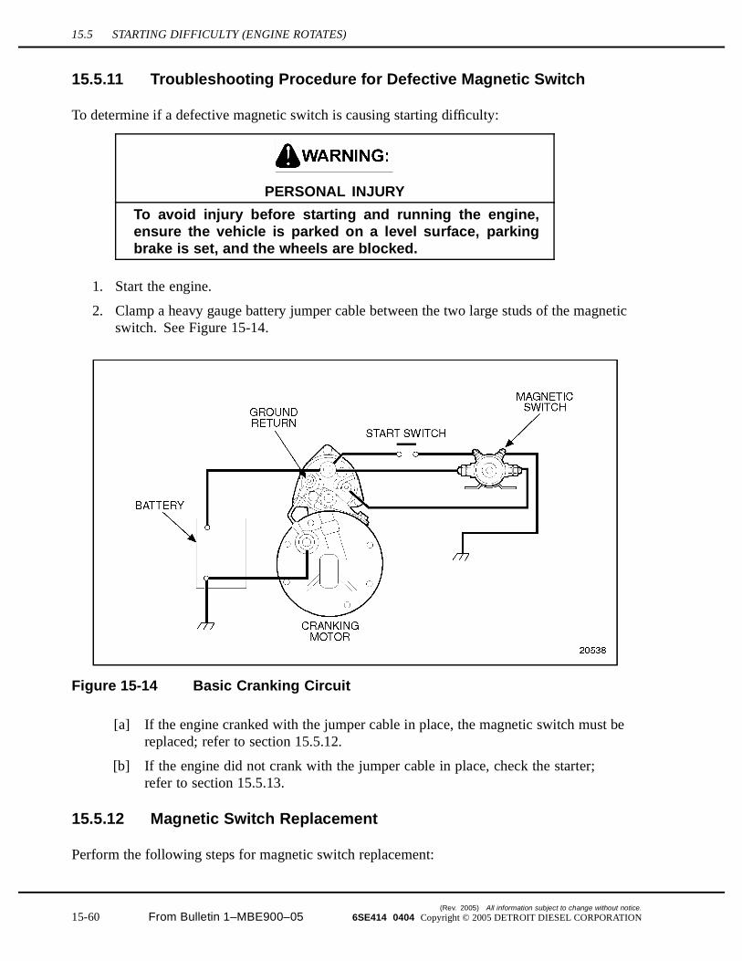
15.5 STARTING DIFFICULTY (ENGINE ROTATES)
15.5.11 Troubleshooting Procedure for Defective Magnetic Switch
To determine if a defective magnetic switch is causing starting difficulty:
PERSONAL INJURY
To avoid injury before starting and running the engine,ensure the vehicle is parked on a level surface, parkingbrake is set, and the wheels are blocked.
1. Start the engine.
2. Clamp a heavy gauge battery jumper cable between the two large studs of the magneticswitch. See Figure 15-14.
Figure 15-14 Basic Cranking Circuit
[a] If the engine cranked with the jumper cable in place, the magnetic switch must bereplaced; refer to section 15.5.12.
[b] If the engine did not crank with the jumper cable in place, check the starter;refer to section 15.5.13.
15.5.12 Magnetic Switch Replacement
Perform the following steps for magnetic switch replacement:
(Rev. 2005) All information subject to change without notice.
15-60 From Bulletin 1–MBE900–05 6SE414 0404 Copyright © 2005 DETROIT DIESEL CORPORATION
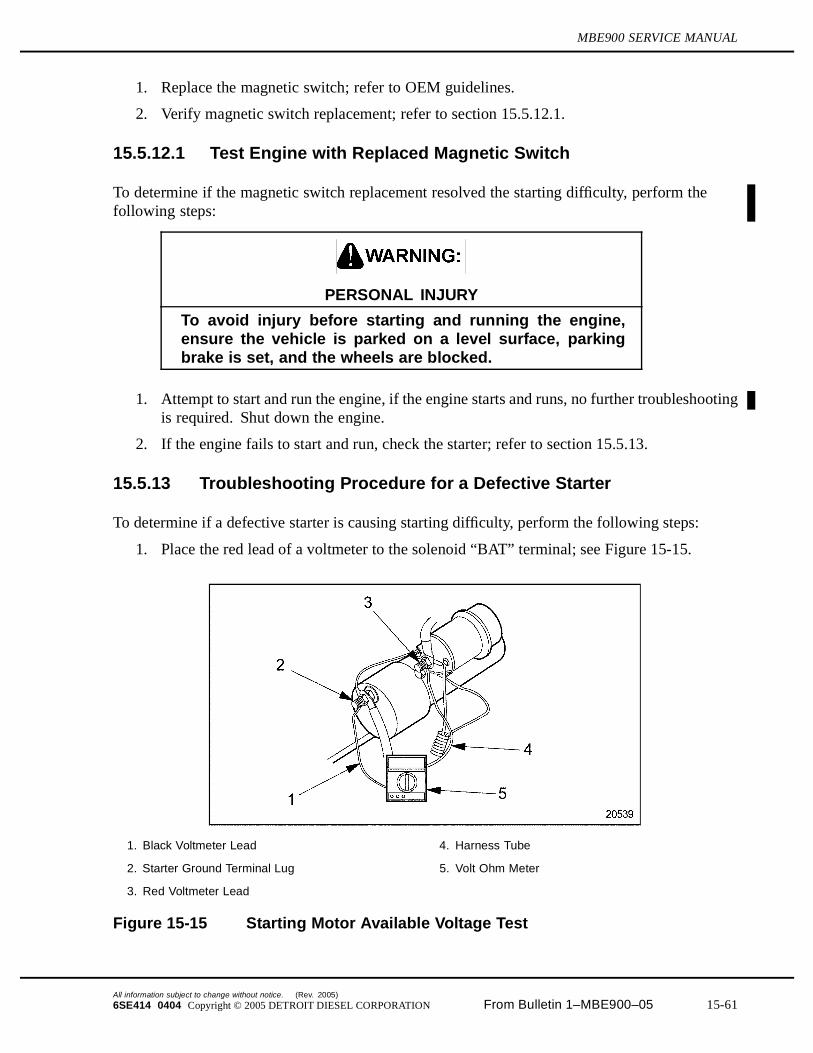
MBE900 SERVICE MANUAL
1. Replace the magnetic switch; refer to OEM guidelines.
2. Verify magnetic switch replacement; refer to section 15.5.12.1.
15.5.12.1 Test Engine with Replaced Magnetic Switch
To determine if the magnetic switch replacement resolved the starting difficulty, perform thefollowing steps:
PERSONAL INJURY
To avoid injury before starting and running the engine,ensure the vehicle is parked on a level surface, parkingbrake is set, and the wheels are blocked.
1. Attempt to start and run the engine, if the engine starts and runs, no further troubleshootingis required. Shut down the engine.
2. If the engine fails to start and run, check the starter; refer to section 15.5.13.
15.5.13 Troubleshooting Procedure for a Defective Starter
To determine if a defective starter is causing starting difficulty, perform the following steps:
1. Place the red lead of a voltmeter to the solenoid “BAT” terminal; see Figure 15-15.
1. Black Voltmeter Lead 4. Harness Tube
2. Starter Ground Terminal Lug 5. Volt Ohm Meter
3. Red Voltmeter Lead
Figure 15-15 Starting Motor Available Voltage Test
All information subject to change without notice. (Rev. 2005)
6SE414 0404 Copyright © 2005 DETROIT DIESEL CORPORATION From Bulletin 1–MBE900–05 15-61
15.5 STARTING DIFFICULTY (ENGINE ROTATES)
2. Place the black voltmeter lead to the starter ground terminal; see Figure 15-15.
3. Engage the starter switch.
4. View the voltage reading on the meter.
[a] If the voltage is less than specification while cranking the engine, replacement isnecessary; refer to section 15.5.14.
[b] If the voltage is to specification while cranking the engine, check the cranking speed;refer to section 15.5.15.
15.5.14 Starter Replacement
Perform the following steps for starter replacement:
1. Replace the starter. Refer to section 8.1.
2. Verify replacement of starter; refer to section 15.5.14.1.
15.5.14.1 Test Engine with Replaced Starter
To determine if the replaced starter resolved starting difficulty, perform the following steps:
PERSONAL INJURY
To avoid injury before starting and running the engine,ensure the vehicle is parked on a level surface, parkingbrake is set, and the wheels are blocked.
1. Attempt to start and run the engine, if the engine starts and runs, no further troubleshootingis required. Shut down the engine.
2. If the engine fails to start and run, check the cranking speed; refer to section 15.5.15.
15.5.15 Troubleshooting Procedure for Low Cranking Speed
To determine if low cranking speed is causing starting difficulty, install a tachometer to the engineand record engine revolution while cranking the engine. Refer to OEM guidelines.
If the cranking speed is greater than 100 rpm, check the OEM fuel supply valve;refer to section 15.5.17.
If the cranking speed is less than 100 rpm; refer to section 15.5.16.
15.5.16 Low Cranking Speed Repair
Perform the following steps for low cranking speed repair:
1. Drain the engine oil. Refer to section 13.1.4.
(Rev. 2005) All information subject to change without notice.
15-62 From Bulletin 1–MBE900–05 6SE414 0404 Copyright © 2005 DETROIT DIESEL CORPORATION
MBE900 SERVICE MANUAL
2. Remove the oil filter(s).
3. Install new oil filter(s). Refer to section 13.1.4.
4. Refill the lubrication system with new oil.
5. Verify low cranking speed repair; refer to section 15.5.16.1.
15.5.16.1 Test Engine with Replaced Oil
To determine if the replaced oil resolved starting difficulty, perform the following steps:
PERSONAL INJURY
To avoid injury before starting and running the engine,ensure the vehicle is parked on a level surface, parkingbrake is set, and the wheels are blocked.
Attempt to start and run the engine, if the engine starts and runs, no further troubleshootingis required. Shut down the engine.
If the engine fails to start and run, check the fuel supply valve; refer to section 15.5.17.
15.5.17 Troubleshooting Procedure for the Fuel Supply Valve
To determine if the fuel supply valve is causing starting difficulty, check that the fuel supply valveis open; refer to OEM guidelines.
1. If the fuel supply valve is open, check the fuel filters; refer to section 15.5.19.
2. If the fuel supply valve is closed, repair is necessary; refer to section 15.5.18.
15.5.18 Fuel Supply Valve Repair
Perform the following steps for fuel supply valve repair:
1. Correct valve operation or replace valve.
2. Prime the fuel system; refer to section 11.1.5.
3. Verify fuel supply valve repair; refer to section 15.5.18.1.
15.5.18.1 Test Engine with Fuel Supply Valve Open
To determine if opening the fuel supply valve resolved starting difficulty, perform the followingsteps :
All information subject to change without notice. (Rev. 2005)
6SE414 0404 Copyright © 2005 DETROIT DIESEL CORPORATION From Bulletin 1–MBE900–05 15-63
15.5 STARTING DIFFICULTY (ENGINE ROTATES)
PERSONAL INJURY
To avoid injury before starting and running the engine,ensure the vehicle is parked on a level surface, parkingbrake is set, and the wheels are blocked.
1. Attempt to start and run the engine, if the engine starts and runs, no further troubleshootingis required. Shut down the engine.
2. If the engine fails to start and run, check the fuel filters; refer to section 15.5.19.
15.5.19 Troubleshooting Procedure for Plugged Fuel Filter(s)
To determine if a plugged fuel filter(s) is causing starting difficulty, perform the following steps:
1. Disconnect the fuel line return hose from the fitting located at the fuel tank.
2. Place the opened end of the fuel line into a five gallon container.
PERSONAL INJURY
To avoid injury before starting and running the engine,ensure the vehicle is parked on a level surface, parkingbrake is set, and the wheels are blocked.
3. Start the engine.
4. Run the engine at 1000 rpm.
5. Clock fuel rate for one minute.
6. Measure the amount of fuel delivered into the container.
[a] If the fuel flow is greater than 1.7 L/min. (0.5 gal/min.) and aerated (small bubbles),check for air in fuel; refer to section 15.5.23.
[b] If the fuel flow is less than 1.7 L/min. (0.5 gal/min.), replace the fuel filters;refer to section 15.5.20.
15.5.20 Plugged Fuel Filter(s) Replacement
Perform the following steps to replace the fuel filter(s):
1. Replace the fuel filter; refer to section 13.1.3.
2. Test the engine to determine if starting has been improved; refer to section 15.5.20.1.
(Rev. 2005) All information subject to change without notice.
15-64 From Bulletin 1–MBE900–05 6SE414 0404 Copyright © 2005 DETROIT DIESEL CORPORATION
MBE900 SERVICE MANUAL
15.5.20.1 Test Engine with Replaced Fuel Filters
To determine if the replaced fuel filters resolved starting difficulty, perform the following steps:
PERSONAL INJURY
To avoid injury before starting and running the engine,ensure the vehicle is parked on a level surface, parkingbrake is set, and the wheels are blocked.
1. Attempt to start and run the engine, if the engine starts and runs, no further troubleshootingis required. Shut down the engine.
2. If the engine fails to start and run, check the fuel pump; refer to section 15.5.21.
15.5.21 Troubleshooting Procedure for Fuel Pump
To determine if the fuel pump is causing starting difficulty, perform the following:
PERSONAL INJURY
To avoid injury before starting and running the engine,ensure the vehicle is parked on a level surface, parkingbrake is set, and the wheels are blocked.
1. Start and run the engine. If pressure at idle speed (600–650 rpm) is -0.09 to -0.12 bar (-1.3to -1.7), check for aerated fuel. Refer to section 15.5.23.
2. If pressure at idle speed (600–650 rpm) is less than -0.09 to -0.12 bar (-1.3 to -1.7),refer to Table 15-35.
3. If pressure at idle speed (600–650 rpm) is greater than -0.09 to -0.12 bar (-1.3 to -1.7),refer to Table 15-36.
4. If a no pressure reading is observed, replace the fuel pump, refer to section2.15.1.
Check fuel intake pressure upstream of fuel pump.
15.5.22 Fuel Pump Replacement
Perform the following steps for fuel pump replacement:
1. Replace the fuel pump: refer to section 2.15.1.
All information subject to change without notice. (Rev. 2005)
6SE414 0404 Copyright © 2005 DETROIT DIESEL CORPORATION From Bulletin 1–MBE900–05 15-65
15.5 STARTING DIFFICULTY (ENGINE ROTATES)
PERSONAL INJURY
To avoid injury before starting and running the engine,ensure the vehicle is parked on a level surface, parkingbrake is set, and the wheels are blocked.
2. Test the engine to determine if starting has been improved; refer to section 15.5.22.1.
15.5.22.1 Engine Test with Replaced Fuel Pump
To determine if the replaced fuel pump resolved starting difficulty, perform the following steps:
PERSONAL INJURY
To avoid injury before starting and running the engine,ensure the vehicle is parked on a level surface, parkingbrake is set, and the wheels are blocked.
1. Attempt to start and run the engine, if the engine starts and runs, no further troubleshootingis required. Shut down the engine.
2. If the engine fails to start and run, check for aerated fuel; refer to section 15.5.23.
15.5.23 Troubleshooting Procedure for Aerated Fuel
To determine if aerated fuel is causing starting difficulty, perform the following steps:
1. Disconnect the fuel line return hose from the fitting located at the fuel tank; refer to OEMguidelines.
2. Place the opened end of the fuel line into a suitable container.
(Rev. 2005) All information subject to change without notice.
15-66 From Bulletin 1–MBE900–05 6SE414 0404 Copyright © 2005 DETROIT DIESEL CORPORATION
MBE900 SERVICE MANUAL
PERSONAL INJURY
To avoid injury before starting and running the engine,ensure the vehicle is parked on a level surface, parkingbrake is set, and the wheels are blocked.
3. Start the engine.
4. Run the engine at 1000 rpm.
5. Visually check to see if air bubbles are rising to the surface of the fuel within the container.
[a] If air bubbles are present, repair is necessary; refer to section 15.5.24.
[b] If air bubbles are not present, check for a restrictive air filter. Shut down the engine;refer to section 15.5.25.
15.5.24 Aerated Fuel Resolution
Perform the following steps for aerated fuel resolution:
1. Shut down the engine.
2. Tighten all fuel line connections between fuel tank and fuel pump; refer to OEMguidelines.
3. Visually inspect all fuel lines between fuel tank and fuel pump for leaks.
4. Replace damaged components as required; refer to OEM guidelines.
5. Verify aerated fuel resolution; refer to section 15.5.24.1.
15.5.24.1 Test Engine with Aerated Fuel Resolution
To determine if aerated fuel resolution resolved starting difficulty, perform the following steps:
PERSONAL INJURY
To avoid injury before starting and running the engine,ensure the vehicle is parked on a level surface, parkingbrake is set, and the wheels are blocked.
1. Attempt to start and run the engine, if the engine starts and runs, no further troubleshootingis required. Shut down the engine.
2. If the engine fails to start and run, check for a restrictive air filter; refer to section 15.5.25.
All information subject to change without notice. (Rev. 2005)
6SE414 0404 Copyright © 2005 DETROIT DIESEL CORPORATION From Bulletin 1–MBE900–05 15-67

15.5 STARTING DIFFICULTY (ENGINE ROTATES)
15.5.25 Troubleshooting Procedure for Restrictive Air Filter
To determine if a restrictive air filter is causing starting difficulty, perform the following steps:
1. Remove the air filter element; refer to OEM guidelines.
PERSONAL INJURY
To avoid injury before starting and running the engine,ensure the vehicle is parked on a level surface, parkingbrake is set, and the wheels are blocked.
2. Attempt to start and run the engine.
[a] If the engine starts and runs, no further engine troubleshooting is required. Shutdown the engine.
[b] If the engine fails to start and run, refer to section 15.5.26.
15.5.26 Air Filter Replacement
Perform the following steps for air filter replacement:
1. Visually inspect the air filter for clogging and replace as necessary; refer to OEMguidelines.
2. Visually inspect gaskets for deterioration and replace as necessary; refer to OEMguidelines.
3. Visually inspect air inlets for restrictions and clean as necessary; refer to OEM guidelines.
4. Verify air filter replacement; refer to section 15.5.26.1.
15.5.26.1 Test Engine with Replaced Air Filter
To determine if the replaced air filter resolved starting difficult, perform the following steps:
PERSONAL INJURY
To avoid injury before starting and running the engine,ensure the vehicle is parked on a level surface, parkingbrake is set, and the wheels are blocked.
1. Attempt to start the engine, if the engine starts and runs, no further troubleshooting isrequired. Shut down the engine.
2. If the engine fails to start and run, check compression; refer to section 15.5.27.
(Rev. 2005) All information subject to change without notice.
15-68 From Bulletin 1–MBE900–05 6SE414 0404 Copyright © 2005 DETROIT DIESEL CORPORATION
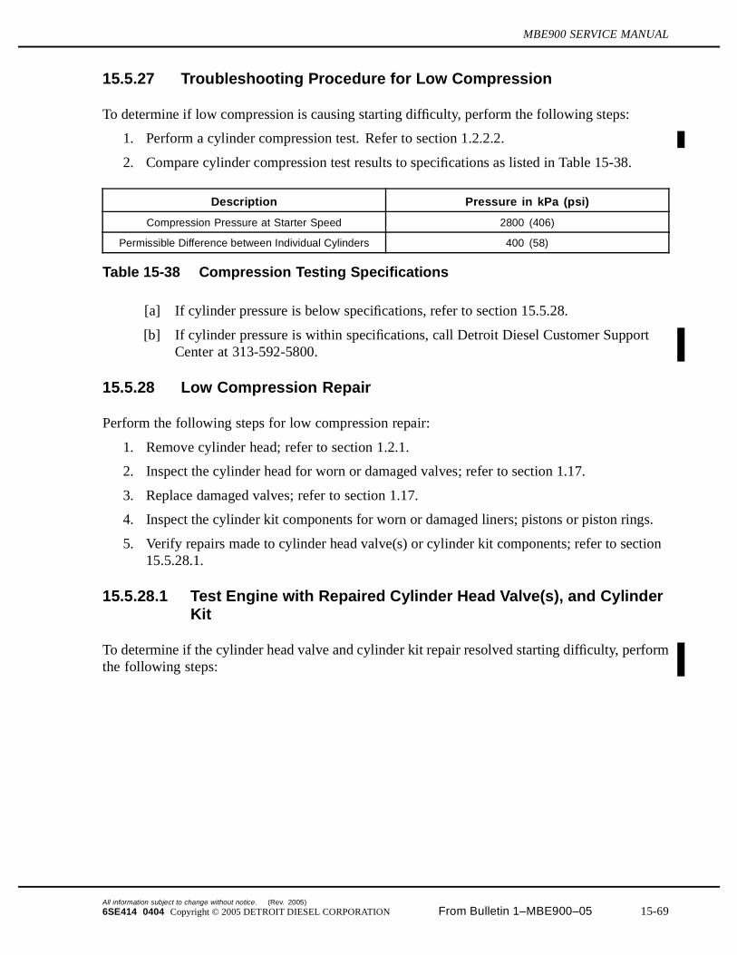
MBE900 SERVICE MANUAL
15.5.27 Troubleshooting Procedure for Low Compression
To determine if low compression is causing starting difficulty, perform the following steps:
1. Perform a cylinder compression test. Refer to section 1.2.2.2.
2. Compare cylinder compression test results to specifications as listed in Table 15-38.
Description Pressure in kPa (psi)
Compression Pressure at Starter Speed 2800 (406)
Permissible Difference between Individual Cylinders 400 (58)
Table 15-38 Compression Testing Specifications
[a] If cylinder pressure is below specifications, refer to section 15.5.28.
[b] If cylinder pressure is within specifications, call Detroit Diesel Customer SupportCenter at 313-592-5800.
15.5.28 Low Compression Repair
Perform the following steps for low compression repair:
1. Remove cylinder head; refer to section 1.2.1.
2. Inspect the cylinder head for worn or damaged valves; refer to section 1.17.
3. Replace damaged valves; refer to section 1.17.
4. Inspect the cylinder kit components for worn or damaged liners; pistons or piston rings.
5. Verify repairs made to cylinder head valve(s) or cylinder kit components; refer to section15.5.28.1.
15.5.28.1 Test Engine with Repaired Cylinder Head Valve(s), and CylinderKit
To determine if the cylinder head valve and cylinder kit repair resolved starting difficulty, performthe following steps:
All information subject to change without notice. (Rev. 2005)
6SE414 0404 Copyright © 2005 DETROIT DIESEL CORPORATION From Bulletin 1–MBE900–05 15-69
15.5 STARTING DIFFICULTY (ENGINE ROTATES)
PERSONAL INJURY
To avoid injury before starting and running the engine,ensure the vehicle is parked on a level surface, parkingbrake is set, and the wheels are blocked.
1. Attempt to start and run the engine, if the engine starts and runs, no further troubleshootingis required. Shut down the engine.
2. If the engine fails to start and run, call the Detroit Diesel Customer Support Center at313-592-5800.
(Rev. 2005) All information subject to change without notice.
15-70 From Bulletin 1–MBE900–05 6SE414 0404 Copyright © 2005 DETROIT DIESEL CORPORATION
MBE900 SERVICE MANUAL
15.6 NO START (ENGINE WILL NOT ROTATE)
There are several causes for the engine to not start. These probable causes are:
Discharged Battery Defective Magnetic Switch Defective Starter Internal Engine Damage
15.6.1 Troubleshooting Procedure for Discharged Battery
To determine if a discharged battery is causing the engine not to start, measure and record thevoltage at the battery terminals; refer to OEM guidelines.
1. If, after charging, the voltage recorded is below OEM specifications, voltage is between10.5 - 14 volts (21 - 26 volts for a 24-volt system), and the engine failed to start,replacement is necessary; refer to section 15.6.2.
2. If the voltage recorded is at recommended OEM specifications and the engine failed tostart, check the magnetic switch; refer to section 15.6.3.
15.6.2 Discharged Battery Resolution
Perform the following steps for battery replacement:
1. Replace the battery; refer to OEM guidelines.
2. Verify replacement of the battery; refer to section 15.6.2.1.
15.6.2.1 Test Engine with New Battery
To determine if the new battery resolved the no start condition, perform the following steps:
PERSONAL INJURY
To avoid injury before starting and running the engine,ensure the vehicle is parked on a level surface, parkingbrake is set, and the wheels are blocked.
1. Attempt to start and run the engine, if the engine starts and runs, no further troubleshootingis required. Shut down the engine.
2. If the engine fails to start or run, check the magnetic switch; refer to section 15.6.3.
15.6.3 Troubleshooting Procedure for a Defective Magnetic Switch
To determine if a defective magnetic switch is causing no start:
All information subject to change without notice. (Rev. 2005)
6SE414 0404 Copyright © 2005 DETROIT DIESEL CORPORATION From Bulletin 1–MBE900–05 15-71
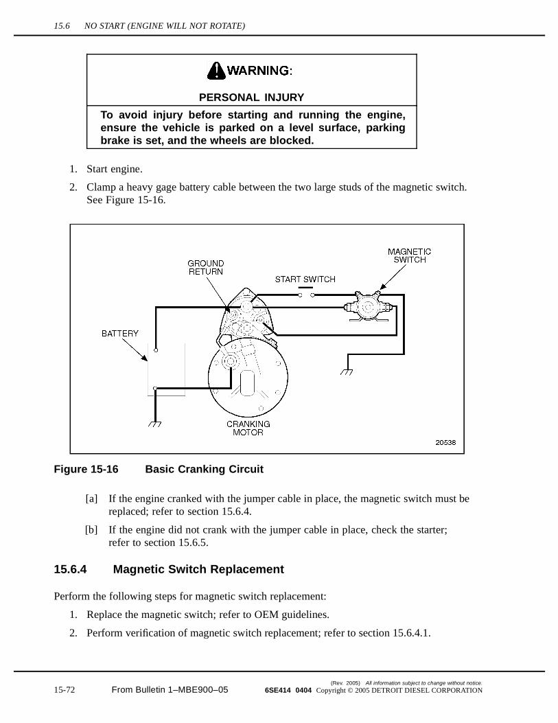
15.6 NO START (ENGINE WILL NOT ROTATE)
PERSONAL INJURY
To avoid injury before starting and running the engine,ensure the vehicle is parked on a level surface, parkingbrake is set, and the wheels are blocked.
1. Start engine.
2. Clamp a heavy gage battery cable between the two large studs of the magnetic switch.See Figure 15-16.
Figure 15-16 Basic Cranking Circuit
[a] If the engine cranked with the jumper cable in place, the magnetic switch must bereplaced; refer to section 15.6.4.
[b] If the engine did not crank with the jumper cable in place, check the starter;refer to section 15.6.5.
15.6.4 Magnetic Switch Replacement
Perform the following steps for magnetic switch replacement:
1. Replace the magnetic switch; refer to OEM guidelines.
2. Perform verification of magnetic switch replacement; refer to section 15.6.4.1.
(Rev. 2005) All information subject to change without notice.
15-72 From Bulletin 1–MBE900–05 6SE414 0404 Copyright © 2005 DETROIT DIESEL CORPORATION
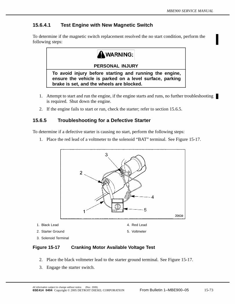
MBE900 SERVICE MANUAL
15.6.4.1 Test Engine with New Magnetic Switch
To determine if the magnetic switch replacement resolved the no start condition, perform thefollowing steps:
PERSONAL INJURY
To avoid injury before starting and running the engine,ensure the vehicle is parked on a level surface, parkingbrake is set, and the wheels are blocked.
1. Attempt to start and run the engine, if the engine starts and runs, no further troubleshootingis required. Shut down the engine.
2. If the engine fails to start or run, check the starter; refer to section 15.6.5.
15.6.5 Troubleshooting for a Defective Starter
To determine if a defective starter is causing no start, perform the following steps:
1. Place the red lead of a voltmeter to the solenoid “BAT” terminal. See Figure 15-17.
1. Black Lead 4. Red Lead
2. Starter Ground 5. Voltmeter
3. Solenoid Terminal
Figure 15-17 Cranking Motor Available Voltage Test
2. Place the black voltmeter lead to the starter ground terminal. See Figure 15-17.
3. Engage the starter switch.
All information subject to change without notice. (Rev. 2005)
6SE414 0404 Copyright © 2005 DETROIT DIESEL CORPORATION From Bulletin 1–MBE900–05 15-73

15.6 NO START (ENGINE WILL NOT ROTATE)
4. View the voltage reading on the meter.
[a] If the voltage is less than specification (refer to OEM guidelines) while cranking theengine, replace starter; refer to section 15.6.6.
[b] If the voltage is to specification (refer to OEM guidelines) while attempting to crankthe engine, check for internal engine damage; refer to section 15.6.7.
15.6.6 Starter Replacement
Perform the following steps for starter replacement:
1. Replace the starter; refer to section 8.1.
2. Verify replacement of starter; refer to section 15.6.6.1.
15.6.6.1 Test Engine with New Starter
To determine if the new starter resolved no-start conditions, perform the following steps:
PERSONAL INJURY
To avoid injury before starting and running the engine,ensure the vehicle is parked on a level surface, parkingbrake is set, and the wheels are blocked.
Attempt to start and run the engine, if the engine starts and runs, no further troubleshootingis required. Shut down the engine.
If the engine fails to start or run, check for internal engine damage. Refer to section 15.6.7.
15.6.7 Troubleshooting Procedure for Internal Engine Damage
To determine if internal engine damage is causing no-start condition, perform the following steps:
1. Install a 3/4 in. breaker bar or ratchet and attempt to bar the engine over by hand.
2. Determine the severity of internal engine damage.
[a] If the engine rotates freely, check the DDEC-ECU wiring harness; refer to section15.5.1.
[b] If the engine binds and will not rotate freely, replace crankshaft bearings;refer to section 1.6 and cylinder liners.
15.6.8 Internal Engine Damage Replacement
Perform the following steps for crankshaft bearings, and cylinder liner replacement:
1. Replace the crankshaft bearings; refer to section 1.6.
(Rev. 2005) All information subject to change without notice.
15-74 From Bulletin 1–MBE900–05 6SE414 0404 Copyright © 2005 DETROIT DIESEL CORPORATION
MBE900 SERVICE MANUAL
2. Replace the cylinder liners.
3. Verify replacement of components; refer to section 15.6.8.1.
15.6.8.1 Test Engine with Replaced Components
To determine if the new components resolved no start condition, perform the following steps:
PERSONAL INJURY
To avoid injury before starting and running the engine,ensure the vehicle is parked on a level surface, parkingbrake is set, and the wheels are blocked.
1. Attempt to start and run the engine, if the engine starts and runs, no further troubleshootingis required. Shut down the engine.
2. If the engine fails to start or run, call Detroit Diesel Customer Support Center at313-592-5800.
All information subject to change without notice. (Rev. 2005)
6SE414 0404 Copyright © 2005 DETROIT DIESEL CORPORATION From Bulletin 1–MBE900–05 15-75
15.7 EXCESSIVE OIL CONSUMPTION
15.7 EXCESSIVE OIL CONSUMPTION
DDC recommends a vehicle accumulate at least 20,000 miles (or 2nd oil change) for oilconsumption to stabilize. Oil consumption rates above 700 miles/quart are considered normal. Ahigh mileage engine will tend to be less. There are several causes for excessive oil consumption.These probable causes are:
Miscalibrated Dipstick External Oil Leaks Leaking Oil Heat Exchanger Core Defective Air Compressor Defective Turbocharger Worn or Damaged Valve or Cylinder Kit
15.7.1 Troubleshooting Procedure for Miscalibrated Dipstick
To determine if an overfilled crankcase is causing excessive oil consumption, perform thefollowing:
1. Ensure the vehicle is parked on level ground.
2. Drain the oil pan. Refill oil pan to the proper capacity. Refer to section 13.1.4.
[a] If a calibration check indicates that the oil level is off by more than 2.0 mm (0.079in.), contact Detroit Diesel Customer Support Center at 313-592-5800.
[b] Check for oil leaks; refer to section 15.7.2.
15.7.2 Troubleshooting Procedure for External Oil Leaks
To determine if oil leaks are causing excessive oil consumption, perform the following:
1. Steam clean the engine.
PERSONAL INJURY
To avoid injury before starting and running the engine,ensure the vehicle is parked on a level surface, parkingbrake is set, and the wheels are blocked.
2. Start and run the engine to operating temperature: 88°C (190°F).
3. Check for leaks at oil lines, connections, mating joints, seals, and gaskets.
[a] If no oil leaks are found, shut down the engine and check for a leaking oil cooler core;refer to section 15.7.4.
[b] If oil leaks are found, shut down the engine; refer to section 15.7.3.
(Rev. 2005) All information subject to change without notice.
15-76 From Bulletin 1–MBE900–05 6SE414 0404 Copyright © 2005 DETROIT DIESEL CORPORATION
MBE900 SERVICE MANUAL
15.7.3 Engine Oil Leak Repair
Perform the following steps, as necessary, to resolve engine oil leaks:
1. Repair or replace components leaking oil; refer to chapter 3.
2. Verify repairs made to correct oil leaks; refer to section 15.7.3.1.
15.7.3.1 Test Engine with Repairs Made to Correct Oil Leaks
Perform the following steps to determine if the repairs resolved the oil leaks:
PERSONAL INJURY
To avoid injury before starting and running the engine,ensure the vehicle is parked on a level surface, parkingbrake is set, and the wheels are blocked.
1. Start and run the engine to operating temperature: 88°C (190°F).
2. Shut down the engine.
3. Check the engine for oil leaks.
[a] If no oil leaks are observed, check for a leaking oil heat exchanger core;refer to section 15.7.4.
[b] If external oil leaks are present, refer to section 15.7.3 and repeat.
15.7.4 Troubleshooting Procedure for a Leaking Oil Heat ExchangerCore
To determine if a leaking oil heat exchanger core is causing excessive oil consumption, performthe following:
1. Check for oil in the engine coolant or radiator.
[a] If oil is present in either the engine coolant or radiator; go to step 2.
[b] If no oil is present in either the engine coolant or radiator, check for a defectiveair compressor; refer to section 15.7.5.
2. Remove the oil heat exchanger core and housing.
3. Clean both the oil side and water side of the oil heat exchanger core.
4. Visually inspect the core for cracks.
[a] If cracks are present, replace oil heat exchanger core. Refer to section 3.6.1. Verifythe replacement of the oil heat exchanger core, refer to section 15.7.4.1
All information subject to change without notice. (Rev. 2005)
6SE414 0404 Copyright © 2005 DETROIT DIESEL CORPORATION From Bulletin 1–MBE900–05 15-77
15.7 EXCESSIVE OIL CONSUMPTION
[b] If no cracks are present, complete a lube oil consumption report; call the DetroitDiesel Customer Support Center at 313-592-5800 for a form.
15.7.4.1 Test Engine with New Oil Heat Exchanger Core
Perform the following steps to determine if the replaced oil heat exchanger core reduced theoil consumption:
PERSONAL INJURY
To avoid injury before starting and running the engine,ensure the vehicle is parked on a level surface, parkingbrake is set, and the wheels are blocked.
1. Start and run the engine to operating temperature: 88°C (190°F).
2. Shut down the engine.
3. Check the engine coolant for the presence of oil.
[a] If no oil is present in the coolant, perform a lube oil consumption test report;refer to section 15.7.4.2.
[b] If oil is present in the coolant, check for a defective turbocharger. Refer to section15.7.6.
15.7.4.2 Test Engine for Reduced Oil Consumption
Perform a lube oil consumption report; call the Detroit Diesel Customer Support Center at313-592-5800 for a form.
Review the oil consumption report.
1. If the oil consumption report data is within specifications, check for defective aircompressor; refer to section 15.7.5.
2. If the oil consumption report data is not within specifications, call Detroit Diesel CustomerSupport Center at 313-592-5800.
15.7.5 Troubleshooting Procedure for a Defective Air Compressor
To determine if a defective air compressor is causing excessive oil consumption, perform thefollowing:
1. Perform a crankcase pressure test and record the test results. Refer to section 15.4.10.1.
(Rev. 2005) All information subject to change without notice.
15-78 From Bulletin 1–MBE900–05 6SE414 0404 Copyright © 2005 DETROIT DIESEL CORPORATION

MBE900 SERVICE MANUAL
2. Disconnect the air discharge line from the air compressor. See Figure 15-18;refer to section 10.1.1.
1. Discharge Port 4. Unloader Port
2. Unloader Air Line 5. Discharge Air Line
3. Intake Air Line 6. Air Compressor
Figure 15-18 Air Line Attachments
3. Repeat step 1 and record the results.
4. Compare the results of test one with test two.
[a] If the engine crankcase pressure remained the same, check the turbocharger;refer to section 15.7.6.
[b] If the engine crankcase pressure decreased, replace the air compressor; refer to section10.1.1. Verify the replaced (or new) air compressor, refer to section 15.7.5.1.
15.7.5.1 Test Engine with Repaired Air Compressor
Perform the following steps to determine if the replaced (or new) air compressor resolved theexcessive crankcase pressure:
All information subject to change without notice. (Rev. 2005)
6SE414 0404 Copyright © 2005 DETROIT DIESEL CORPORATION From Bulletin 1–MBE900–05 15-79
15.7 EXCESSIVE OIL CONSUMPTION
PERSONAL INJURY
To avoid injury before starting and running the engine,ensure the vehicle is parked on a level surface, parkingbrake is set, and the wheels are blocked.
1. Start and run the engine.
2. Perform a crankcase pressure test. Refer to section 15.4.10.1.
[a] If the engine crankcase pressure exceeds 0.62 kPa (2.5 in. H2O), shut down the
engine. Check for defective turbocharger. refer to section 15.7.6.
[b] If the engine crankcase pressure is within 0.62 kPa (2.5 in. H2O), shut down the
engine; no further troubleshooting is required.
15.7.6 Troubleshooting Procedure for a Defective Turbocharger
To determine if a defective turbocharger is causing excessive oil consumption, perform thefollowing:
1. Remove the turbocharger drain line connected to the crankcase and place the drain lineinto a suitable container.
2. Perform a crankcase pressure test. Refer to section 15.4.10.1.
[a] If the engine crankcase pressure is less than 0.62 kPa (2.5 in. H2O), shut down the
engine. Replace the turbocharger; refer to section 6.4.2. Verify the replacement ofthe turbocharger, refer to section 15.7.6.1.
[b] If the engine crankcase pressure indicates no change, shut down the engine. Checkfor worn or damaged valve or cylinder kit. Refer to section 15.7.7.
15.7.6.1 Test Engine with New Turbocharger
Perform the following steps to determine if a new turbocharger resolved the excessive crankcasepressure:
1. Remove the turbocharger drain line connected to the crankcase and place the drain lineinto a suitable container.
2. Perform a crankcase pressure test. Refer to section 15.4.10.1.
[a] If the engine crankcase pressure is greater than 0.62 kPa (2.5 in. H2O), check for
worn or damaged valve or cylinder kit; shut down the engine. Refer to section 15.7.7.
[b] If the engine crankcase pressure is 0.62 kPa (2.5 in. H2O) or less, no further
troubleshooting is required. Shut down the engine.
(Rev. 2005) All information subject to change without notice.
15-80 From Bulletin 1–MBE900–05 6SE414 0404 Copyright © 2005 DETROIT DIESEL CORPORATION
MBE900 SERVICE MANUAL
15.7.7 Troubleshooting Procedure for Worn or Damaged Valve orCylinder Kit
A loss of cylinder pressure can cause increased oil consumption. The detection and elimination ofcylinder pressure losses is vital to engine life and efficient operation. To assist the mechanic ineffectively measuring the loss of cylinder pressure, and locating the source of abnormal leaks inindividual cylinders, the following test procedure has been developed:
1. Move the vehicle requiring test to the chassis dynamometer; refer to OEM guidelines.
2. Disconnect the air compressor and remove; refer to section 10.1.1.
PERSONAL INJURY
To avoid injury before starting and running the engine,ensure the vehicle is parked on a level surface, parkingbrake is set, and the wheels are blocked.
3. Start the engine.
4. Run the engine and bring the engine coolant temperature to normal operating range,approximately 88-96°C (190-205°F).
5. Run the vehicle to full load and rated speed.
6. Perform a crankcase pressure test. Refer to section 15.4.10.1.
7. Shut down the engine.
8. Remove the vehicle from the chassis dynamometer.
9. Review the crankcase pressure test results.
[a] If the crankcase pressure exceeds 0.62 kPa (2.5 in. H2O), repair worn or damaged
valve(s) or cylinder kit; refer to section 15.7.8.
[b] If the crankcase pressure was less than or equal to 0.62 kPa (2.5 in. H2O), perform
a cylinder compression test. Refer to section 1.2.2.2.
10. Compare the cylinder compression test results to specifications as listed in Table 1-10.
[a] If the cylinder compression is below specifications, repair worn or damaged valve(s)or cylinder kit; refer to section 15.7.8.
[b] If the cylinder compression is within specifications, call Detroit Diesel CustomerSupport Center at 313-592-5800.
15.7.8 Worn or Damaged Valve(s) or Cylinder Kit(s) Repair
Perform the following steps to repair worn or damaged valve(s) and cylinder kit(s):
1. Remove the cylinder head; refer to section 1.2.1.
All information subject to change without notice. (Rev. 2005)
6SE414 0404 Copyright © 2005 DETROIT DIESEL CORPORATION From Bulletin 1–MBE900–05 15-81
15.7 EXCESSIVE OIL CONSUMPTION
2. Inspect the cylinder head for worn or damaged valves; refer to section 1.17.
3. Inspect the cylinder kit components for worn or damaged liners; pistons or piston rings;refer to section 1.15.3.1.
4. Replace damaged cylinder kit components.
5. Verify repairs made to cylinder head valve(s) or cylinder kit components; refer to section15.7.8.1.
15.7.8.1 Test Engine with Repaired Cylinder Head Valve(s), and CylinderKit
To determine if the cylinder head valve and cylinder kit repair resolved starting difficulty, performthe following steps:
PERSONAL INJURY
To avoid injury before starting and running the engine,ensure the vehicle is parked on a level surface, parkingbrake is set, and the wheels are blocked.
1. Attempt to start and run the engine, if the engine starts and runs, no further troubleshootingin required.
2. If the engine fails to start and run, call the Detroit Diesel Customer Support Center at313-592-5800.
(Rev. 2005) All information subject to change without notice.
15-82 From Bulletin 1–MBE900–05 6SE414 0404 Copyright © 2005 DETROIT DIESEL CORPORATION
MBE900 SERVICE MANUAL
15.8 EXCESSIVE CRANKCASE PRESSURE
There are several causes for excessive crankcase pressure. These probable causes are:
Obstruction or Damage to Cylinder Head Cover Breather Defective Air Compressor Defective Turbocharger Worn or Damaged Valve or Cylinder Kit
15.8.1 Troubleshooting Procedure for Obstruction or Damage toCylinder Head Cover Breather
To determine if an obstructed or damaged breather is causing excessive crankcase pressure,perform a crankcase pressure test. Refer to section 15.4.10.1.
1. If the engine crankcase pressure is greater than 0.62 kPa (2.5 in. H2O), replace wire mesh
element; refer to section 15.8.2.
2. If the crankcase pressure remained the same, check the air compressor;refer to section 15.8.3.
15.8.2 Cylinder Head Cover Breather Resolution
Perform the following steps to replace wire mesh element:
1. Remove the cylinder head cover; refer to section 1.1.1.
2. Remove the wire mesh element from the cylinder head cover.
3. Install a new wire mesh element to the cylinder head cover.
4. Install the cylinder head cover to the engine; refer to section 1.1.2.
5. Verify replacement of the wire mesh element; refer to section 15.8.2.1.
15.8.2.1 Test Engine with New Wire Mesh Element
Perform the following steps to determine if the new wire mesh element resolved the excessivecrankcase pressure:
All information subject to change without notice. (Rev. 2005)
6SE414 0404 Copyright © 2005 DETROIT DIESEL CORPORATION From Bulletin 1–MBE900–05 15-83
15.8 EXCESSIVE CRANKCASE PRESSURE
PERSONAL INJURY
To avoid injury before starting and running the engine,ensure the vehicle is parked on a level surface, parkingbrake is set, and the wheels are blocked.
1. Start and run the engine.
2. Perform a crankcase pressure test; refer to section 15.4.10.1.
[a] If the engine crankcase pressure is less than 0.62 kPa (2.5 in. H2O), no further
troubleshooting is required. Shut down the engine.
[b] If the engine crankcase pressure is greater than 0.62 kPa (2.5 in. H2O), check the air
compressor; refer to section 15.8.3. Shut down the engine.
15.8.3 Troubleshooting Procedure for Defective Air Compressor
To determine if a defective air compressor is causing excessive crankcase pressure, performthe following:
1. Perform a crankcase pressure test and record the test results. Refer to section 15.4.10.1.
(Rev. 2005) All information subject to change without notice.
15-84 From Bulletin 1–MBE900–05 6SE414 0404 Copyright © 2005 DETROIT DIESEL CORPORATION
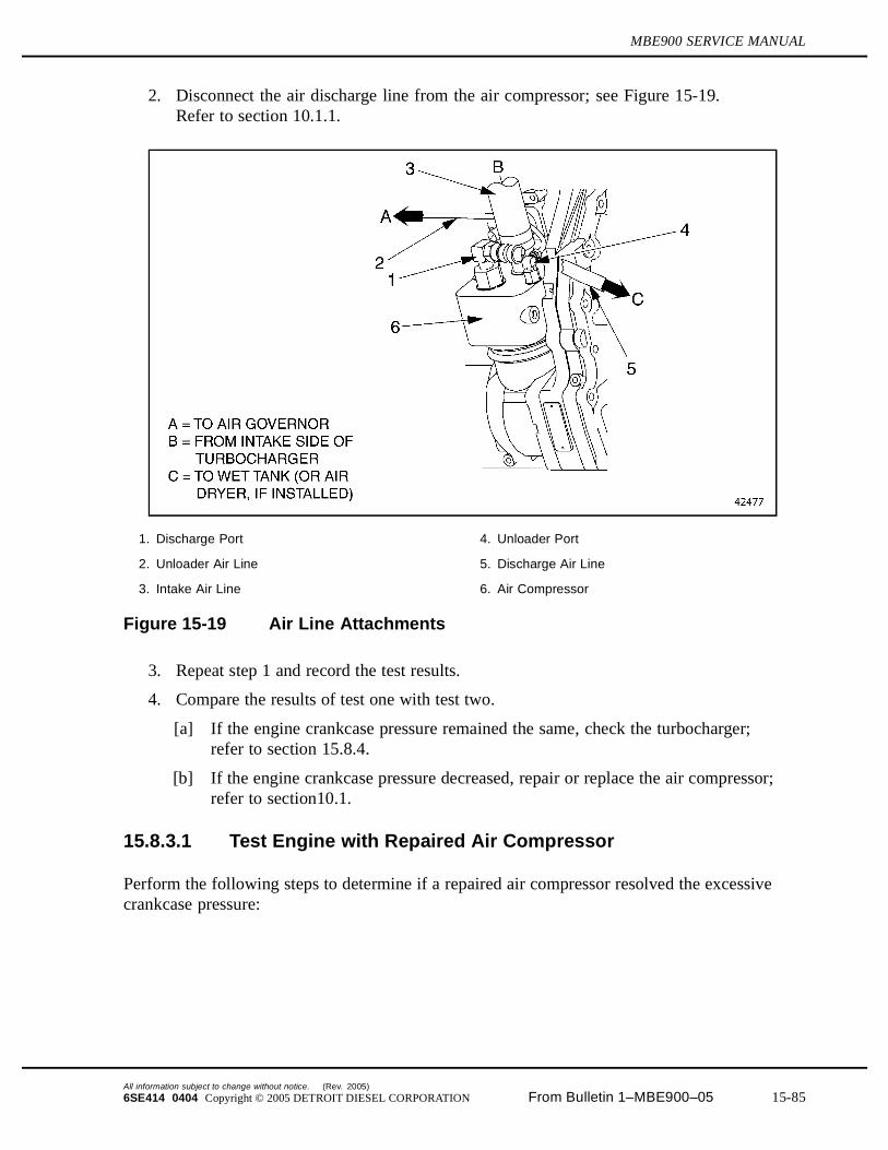
MBE900 SERVICE MANUAL
2. Disconnect the air discharge line from the air compressor; see Figure 15-19.Refer to section 10.1.1.
1. Discharge Port 4. Unloader Port
2. Unloader Air Line 5. Discharge Air Line
3. Intake Air Line 6. Air Compressor
Figure 15-19 Air Line Attachments
3. Repeat step 1 and record the test results.
4. Compare the results of test one with test two.
[a] If the engine crankcase pressure remained the same, check the turbocharger;refer to section 15.8.4.
[b] If the engine crankcase pressure decreased, repair or replace the air compressor;refer to section10.1.
15.8.3.1 Test Engine with Repaired Air Compressor
Perform the following steps to determine if a repaired air compressor resolved the excessivecrankcase pressure:
All information subject to change without notice. (Rev. 2005)
6SE414 0404 Copyright © 2005 DETROIT DIESEL CORPORATION From Bulletin 1–MBE900–05 15-85
15.8 EXCESSIVE CRANKCASE PRESSURE
PERSONAL INJURY
To avoid injury before starting and running the engine,ensure the vehicle is parked on a level surface, parkingbrake is set, and the wheels are blocked.
1. Start and run the engine.
2. Perform a crankcase pressure test; refer to section 15.4.10.1.
[a] If the engine crankcase pressure is within 0.62 kPa (2.5 in. H2O), no further
troubleshooting is required. Shut down the engine.
[b] If the engine crankcase pressure is not within 0.62 kPa (2.5 in. H2O), shut down the
engine. Check the turbocharger; refer to section 15.8.4.
15.8.4 Troubleshooting Procedure for a Defective Turbocharger
To determine if a defective turbocharger is causing excessive crankcase pressure, perform thefollowing:
NOTICE:
Ensure that the engine is not allowed to operate longer thannecessary to perform the crankcase pressure test. A completeloss of crankcase oil will severely damage the engine.
1. Remove the turbocharger drain line connected to the crankcase and place the drain lineinto a suitable container; refer to section 6.4.2.
2. Perform a crankcase pressure test; refer to section 15.4.10.1.
[a] If the engine crankcase pressure is less than 0.62 kPa (2.5 in. H2O), replace the
turbocharger; refer to section 6.4.2. Shut down the engine.
[b] If the engine crankcase pressure indicates no change, check for a worn or damagedvalve or cylinder kit; refer to section 15.8.6. Shut down the engine.
15.8.5 Turbocharger Replacement
Perform the following steps to replace a defective turbocharger:
1. Remove the defective turbocharger from the engine; refer to section 6.4.2.
2. Tag the removed turbocharger for remanufacture.
3. Install a replacement turbocharger to the engine; refer to section 6.4.3.
4. Verify replacement of new turbocharger; refer to section 15.8.5.1.
(Rev. 2005) All information subject to change without notice.
15-86 From Bulletin 1–MBE900–05 6SE414 0404 Copyright © 2005 DETROIT DIESEL CORPORATION

MBE900 SERVICE MANUAL
15.8.5.1 Test Engine with New Turbocharger
To determine if a new turbocharger resolved the excessive crankcase pressure, perform acrankcase pressure test. Refer to section 15.4.10.1.
1. If the engine crankcase pressure is 0.62 kPa (2.5 in. H2O) or less, no further
troubleshooting is required. Shut down the engine.
2. If the engine crankcase pressure is greater than 0.62 kPa (2.5 in. H2O), shut down the
engine. Check for a worn or damaged valve or cylinder kit; refer to section 15.8.6.
15.8.6 Troubleshooting Procedure for Worn or Damaged Valve orCylinder Kit
To determine if a worn or damaged cylinder kit is causing excessive crankcase pressure, performthe following:
1. Move the vehicle requiring test to the chassis dynamometer; refer to OEM guidelines.
2. Remove air compressor; refer to section 10.1.1.
PERSONAL INJURY
To avoid injury before starting and running the engine,ensure the vehicle is parked on a level surface, parkingbrake is set, and the wheels are blocked.
3. Start the engine.
4. Run the engine and bring the engine coolant temperature to normal operating range,approximately 88-96°C (190-205°F).
5. Run the vehicle to full load and rated speed.
6. Attach a manometer calibrated to read pressure kPa or inches of H2O, to the oil dipstick
opening.
7. Measure and record crankcase pressure.
8. Shut down the engine.
9. Remove the vehicle from the chassis dynamometer.
10. Review the crankcase pressure test.
[a] If the crankcase pressure is greater than 0.62 kPa (2.5 in. H2O), go to step 11.
[b] If the crankcase pressure is less than 0.62 kPa (2.5 in. H2O), no further
troubleshooting is required.
11. Perform the cylinder compression test. Refer to section 1.2.2.2.
[a] If cylinder pressure is below specifications, refer to Table and refer to section 15.8.7.
All information subject to change without notice. (Rev. 2005)
6SE414 0404 Copyright © 2005 DETROIT DIESEL CORPORATION From Bulletin 1–MBE900–05 15-87

15.8 EXCESSIVE CRANKCASE PRESSURE
[b] If cylinder pressure is within specifications, call Detroit Diesel Customer SupportCenter at 313-592-5800.
15.8.7 Worn or Damaged Valve or Cylinder Kit Repair
Perform the following steps for a worn or damaged valve or cylinder kit:
1. Remove the cylinder head; refer to section 1.2.1.
2. Inspect the cylinder head for worn or damaged valves; refer to section 1.17.
3. Inspect the cylinder kit components for worn or damaged liners, piston or piston rings;refer to section 1.15.3.1.
4. Verify repair to cylinder valve(s) or cylinder kit components; refer to section 15.8.7.1.
15.8.7.1 Test Engine with Repairs Made to Correct Worn or DamagedValve or Cylinder Kit
Perform the following to determine if the repaired valve or cylinder kit resolved the excessivecrankcase pressure:
1. Move the vehicle requiring test to the chassis dynamometer; refer to OEM guidelines.
2. Disconnect air compressor; refer to section 10.1.1.
PERSONAL INJURY
To avoid injury before starting and running the engine,ensure the vehicle is parked on a level surface, parkingbrake is set, and the wheels are blocked.
3. Start the engine.
4. Run the engine and bring the engine coolant temperature to normal operating range,approximately 88-96°C (190-205°F).
5. Run the vehicle to full load and rated speed.
6. Attach a manometer calibrated to read pressure in kPa or inches of H2O, to the oil dipstick
opening.
7. Measure and record crankcase pressure.
8. Shut down the engine.
9. Remove the vehicle from the chassis dynamometer.
10. Compare the cylinder pressure test results to specifications listed in Table 1-10.
[a] If cylinder pressure is within specifications, no further troubleshooting is required.
(Rev. 2005) All information subject to change without notice.
15-88 From Bulletin 1–MBE900–05 6SE414 0404 Copyright © 2005 DETROIT DIESEL CORPORATION
MBE900 SERVICE MANUAL
[b] If cylinder pressure is not within specifications, call Detroit Diesel Customer SupportCenter at 313-592-5800.
All information subject to change without notice. (Rev. 2005)
6SE414 0404 Copyright © 2005 DETROIT DIESEL CORPORATION From Bulletin 1–MBE900–05 15-89
15.9 EXCESSIVE EXHAUST SMOKE (BLACK OR GRAY)
15.9 EXCESSIVE EXHAUST SMOKE (BLACK OR GRAY)
There are many causes for excessive black or gray exhaust smoke. These probable causes are:
Restricted Air Cleaner Element Restricted or Cracked Charge Air Cooler Faulty Air Intake Manifold Gasket Faulty Exhaust Manifold Gasket Aerated Fuel Faulty Fuel Nozzle Defective Turbocharger Improper Grade of Fuel Faulty EGR valve Incorrectly Adjusted Exhaust Brake Faulty Exhaust Brake Valve Faulty Exhaust Brake Cylinder Faulty Constant Throttle Valve Incorrect Valve Clearance Low Compression
15.9.1 Troubleshooting Procedure for Restricted Air Cleaner Element
To determine if a restrictive air cleaner element is causing excessive black or gray smoke,perform the following:
1. Remove the air filter element from the air cleaner container; refer to OEM guidelines.
2. Visually inspect the air cleaner element for damage or clogging.
[a] If no damage or clogging is found, check the charge air cooler; refer to section 15.9.3.
[b] If damage or clogging is found, refer to section 15.9.2.
15.9.2 Air Filter Element Replacement
Perform the following to replace the air filter element:
1. Remove and replace the damaged or clogged air filter element; refer to OEM guidelines.
2. Verify that replacing the air filter element eliminated the excessive exhaust smoke;refer to section 15.9.2.1.
15.9.2.1 Test the Engine with Replaced Air Filter Element
Perform the following to determine if the new filter element resolved excessive exhaust smoke:
(Rev. 2005) All information subject to change without notice.
15-90 From Bulletin 1–MBE900–05 6SE414 0404 Copyright © 2005 DETROIT DIESEL CORPORATION

MBE900 SERVICE MANUAL
PERSONAL INJURY
To avoid injury before starting and running the engine,ensure the vehicle is parked on a level surface, parkingbrake is set, and the wheels are blocked.
1. Start and run the engine.
2. Run the engine at idle with a no-load condition for approximately five minutes, allowingthe engine coolant to reach normal operating range, approximately 88-96°C (190-205°F).
3. Visually inspect exhaust for excessive smoke.
[a] If the engine exhaust emission appears normal, no further troubleshooting is required.Shut down the engine.
[b] If the engine exhaust emission is excessively black or gray, shut down the engine.Check the charge air cooler; refer to section 15.9.3.
15.9.3 Troubleshooting Procedure for a Restricted or Cracked ChargeAir Cooler
To determine if a charge air cooler is causing excessive exhaust smoke, perform the following:
NOTICE:
To avoid engine damage, follow the installation instructionsprovided with the air-to-air charge air cooler test kit.
1. Visually inspect the core, tanks, and welds for cracks and holes. If charge air cooler failsvisual inspection replace the charge air cooler. Refer to section15.9.4.
2. Pressure test the charge air cooler; refer to section 15.9.3.1.
3. Evaluate the results from pressure testing the charge air cooler.
[a] If the pressure drop is 34 kPa (5 psi) or less in 15 seconds the cooler is good. Checkfor faulty air intake manifold. Refer to section 15.9.5.
[b] If the pressure drop is greater than 34 kPa (5 psi) in 15 seconds, replace the charge aircooler. Refer to section 15.9.4.
All information subject to change without notice. (Rev. 2005)
6SE414 0404 Copyright © 2005 DETROIT DIESEL CORPORATION From Bulletin 1–MBE900–05 15-91
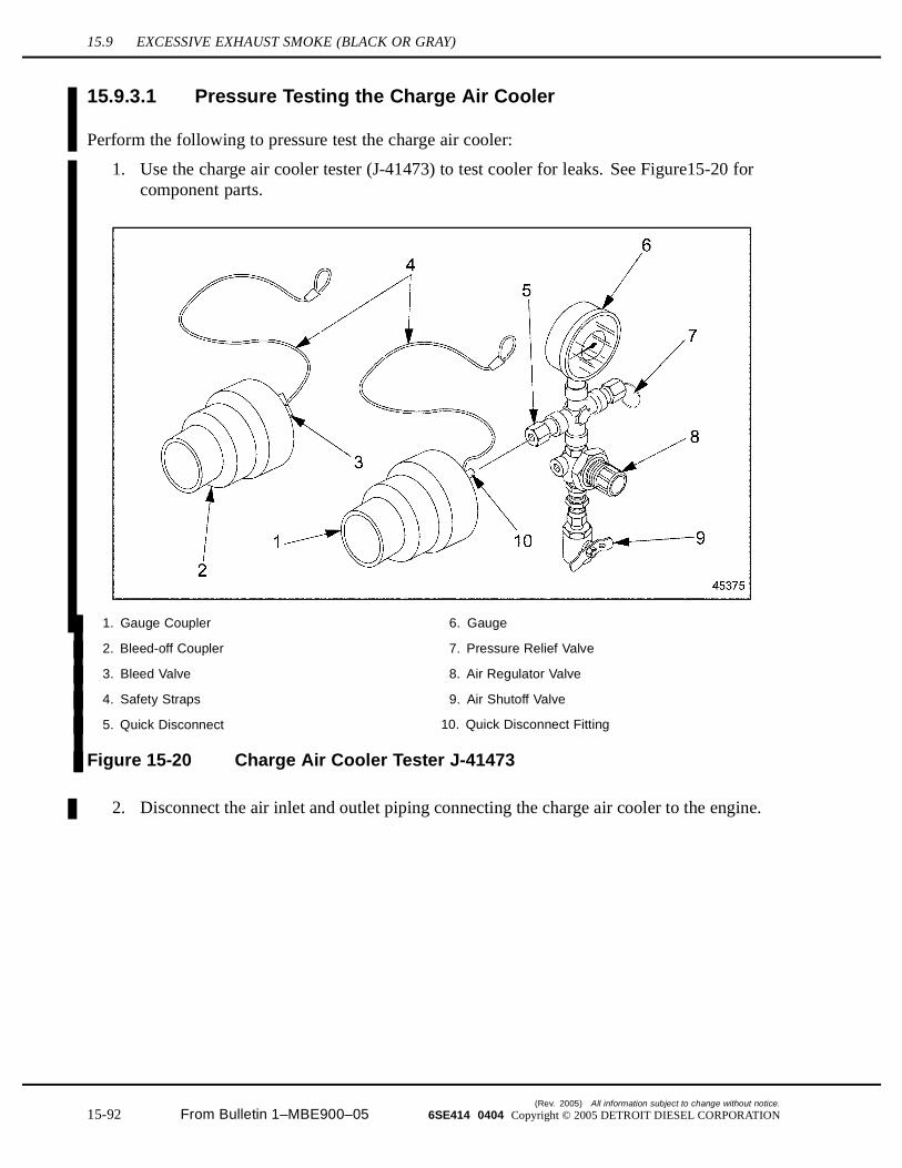
15.9 EXCESSIVE EXHAUST SMOKE (BLACK OR GRAY)
15.9.3.1 Pressure Testing the Charge Air Cooler
Perform the following to pressure test the charge air cooler:
1. Use the charge air cooler tester (J-41473) to test cooler for leaks. See Figure15-20 forcomponent parts.
1. Gauge Coupler 6. Gauge
2. Bleed-off Coupler 7. Pressure Relief Valve
3. Bleed Valve 8. Air Regulator Valve
4. Safety Straps 9. Air Shutoff Valve
5. Quick Disconnect 10. Quick Disconnect Fitting
Figure 15-20 Charge Air Cooler Tester J-41473
2. Disconnect the air inlet and outlet piping connecting the charge air cooler to the engine.
(Rev. 2005) All information subject to change without notice.
15-92 From Bulletin 1–MBE900–05 6SE414 0404 Copyright © 2005 DETROIT DIESEL CORPORATION
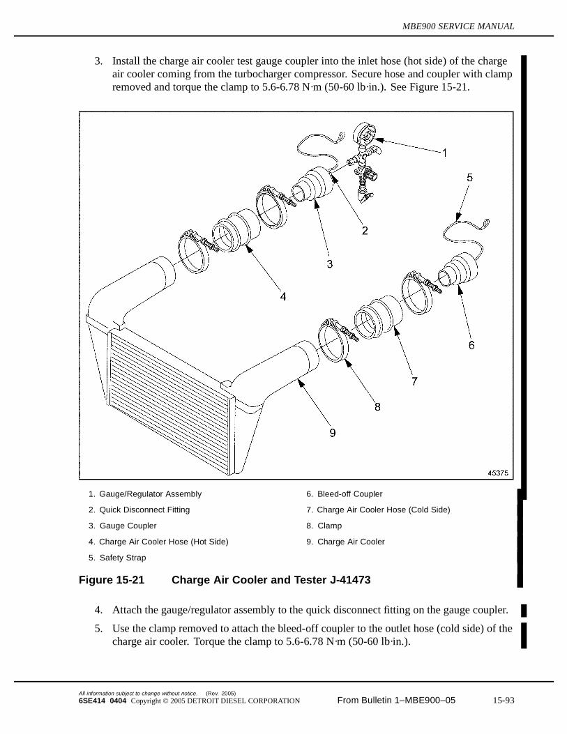
MBE900 SERVICE MANUAL
3. Install the charge air cooler test gauge coupler into the inlet hose (hot side) of the chargeair cooler coming from the turbocharger compressor. Secure hose and coupler with clampremoved and torque the clamp to 5.6-6.78 N·m (50-60 lb·in.). See Figure 15-21.
1. Gauge/Regulator Assembly 6. Bleed-off Coupler
2. Quick Disconnect Fitting 7. Charge Air Cooler Hose (Cold Side)
3. Gauge Coupler 8. Clamp
4. Charge Air Cooler Hose (Hot Side) 9. Charge Air Cooler
5. Safety Strap
Figure 15-21 Charge Air Cooler and Tester J-41473
4. Attach the gauge/regulator assembly to the quick disconnect fitting on the gauge coupler.
5. Use the clamp removed to attach the bleed-off coupler to the outlet hose (cold side) of thecharge air cooler. Torque the clamp to 5.6-6.78 N·m (50-60 lb·in.).
All information subject to change without notice. (Rev. 2005)
6SE414 0404 Copyright © 2005 DETROIT DIESEL CORPORATION From Bulletin 1–MBE900–05 15-93
15.9 EXCESSIVE EXHAUST SMOKE (BLACK OR GRAY)
6. Connect the safety straps on the couplers to any convenient screw on the radiatormounting bracket.
PRESSURIZED AIR AND FLYING PARTICLES
To avoid injury to eye or face, wear a face shield or goggleswhen conducting a pressure test.
7. Attach an air pressure line, with filtered air, to the air shutoff valve and graduallypressurize the charge air cooler to a pressure of 205 kPa (30 psi). If necessary, perform thefollowing steps to adjust the air regulator until the gauge reads 205 kPa (30 psi):
[a] Pull regulator knob outward to unlock.
[b] Turn knob to adjust pressure to 205 kPa (30 psi).
[c] Push the regulator knob back into locked position.
8. Close the air shutoff valve and monitor the gauge with a stop watch for 15 seconds. Noteany decrease in air pressure.
9. Repeat test at least three times to verify results.
[a] In pressure drop is 34 kPa (5 psi) or less in 15 seconds the cooler is good.
[b] If the pressure drop is greater than 34 kPa (5 psi) in 15 seconds, replace the charge aircooler. Refer to section 15.9.4.
10. Slowly release pressure with the charge air cooler by opening the valve in the bleed-offcoupler.
11. Remove all charge air cooler tester pieces and reconnect charge air cooler piping to theengine.
12. Reconnect air inlet and outlet piping to engine. Torque hose clamps to 5.6 - 6.78 N·m(50 - 60 lb·in.).
15.9.4 Charge Air Cooler Replacement
Perform the following steps to replace the charge air cooler:
1. Replace the charge air cooler; refer to OEM guidelines.
2. Verify that the replacement of the charge air cooler eliminated the excessive exhaustsmoke; refer to section 15.9.5.1.
15.9.5 Troubleshooting Procedure for a Faulty Air Intake ManifoldGasket
Perform the following steps to troubleshoot the air intake manifold:
1. Remove the air intake manifold; refer to section 6.2.1.
(Rev. 2005) All information subject to change without notice.
15-94 From Bulletin 1–MBE900–05 6SE414 0404 Copyright © 2005 DETROIT DIESEL CORPORATION

MBE900 SERVICE MANUAL
2. Inspect the air intake manifold and gaskets.
3. Install the air intake manifold with new gaskets; refer to section 6.2.2.
4. Verify repair of the air intake manifold; refer to section 15.9.5.1.
15.9.5.1 Test the Engine with a Replaced Charge Air Cooler or Air IntakeManifold Gasket Replacement
To determine if the replaced charge air cooler or air intake manifold gasket resolved the excessiveexhaust smoke condition, perform the following:
PERSONAL INJURY
To avoid injury before starting and running the engine,ensure the vehicle is parked on a level surface, parkingbrake is set, and the wheels are blocked.
1. Start and run the engine.
2. Run the engine at idle with a no-load condition for approximately five minutes, allowingthe engine coolant to reach normal operating range, approximately 88-96°C (190-205°F).
3. Visually inspect exhaust for excessive black or gray smoke.
[a] If the engine exhaust emission appears normal, no further troubleshooting is required.Shut down the engine.
[b] If the engine exhaust emission is excessively black or gray, shut down the engine.Check for a faulty exhaust system; refer to section 15.9.6.
15.9.6 Troubleshooting Procedure for a Faulty Exhaust System
To determine if a faulty exhaust system is causing excessive black or gray exhaust smoke,perform the following:
1. Drill an 11/32 in. hole in the exhaust pipe, 125 - 305 mm (5 - 12 in.) from the turbochargerexhaust outlet.
NOTE:The tapped hole must be in a comparatively straight section of the turbocharger exhaustoutlet.
2. Tap the hole to accommodate a 1/8 in. pipe plug.
3. Connect a manometer calibrated to read pressure in kPa or inches of Hg to the tapped hole.
All information subject to change without notice. (Rev. 2005)
6SE414 0404 Copyright © 2005 DETROIT DIESEL CORPORATION From Bulletin 1–MBE900–05 15-95
15.9 EXCESSIVE EXHAUST SMOKE (BLACK OR GRAY)
PERSONAL INJURY
To avoid injury before starting and running the engine,ensure the vehicle is parked on a level surface, parkingbrake is set, and the wheels are blocked.
4. Start and run the engine.
5. Run the engine at idle with a no-load condition for approximately five minutes, allowingthe engine coolant to reach normal operating range, approximately 88-96°C (190-205°F).
6. Run the engine speed to full load.
[a] If the exhaust back pressure at full load is less than 12 kPa (3.5 in. Hg), check thefuel injectors and nozzles; refer to section 15.9.10. Shut down the engine.
[b] If the exhaust back pressure at full load is 12 kPa (3.5 in. Hg) or greater,refer to section 15.9.7. Shut down the engine.
15.9.7 Engine Exhaust System Resolution
Perform the following steps to resolve the engine exhaust system concern:
1. Visually inspect the engine exhaust system: refer to OEM guidelines.
2. Repair and replace defective exhaust system components; refer to OEM guidelines
3. Verify exhaust system resolutionrefer to section 15.9.7.1.
15.9.7.1 Test the Engine with Replaced Exhaust System
Perform the following steps to determine if replaced engine exhaust manifold has resolved theexcessive black or gray exhaust smoke condition:
PERSONAL INJURY
To avoid injury before starting and running the engine,ensure the vehicle is parked on a level surface, parkingbrake is set, and the wheels are blocked.
1. Start and run the engine.
2. Run the engine at idle with a no-load condition for approximately five minutes, allowingthe engine coolant to reach normal operating range, approximately 88-96°C (190-205°F).
3. Visually inspect exhaust for excessive smoke.
(Rev. 2005) All information subject to change without notice.
15-96 From Bulletin 1–MBE900–05 6SE414 0404 Copyright © 2005 DETROIT DIESEL CORPORATION
MBE900 SERVICE MANUAL
[a] If the engine exhaust emission appears normal, no further troubleshooting is required.Shut down the engine.
[b] If the engine exhaust emission is excessively black or gray, shut down the engine.Check the fuel nozzles; refer to section 15.9.8.
15.9.8 Troubleshooting Procedure for Aerated Fuel
To determine if aerated fuel is causing excessive exhaust smoke, perform the following steps:
1. Disconnect the fuel line return hose from the fitting located at the fuel tank; refer to OEMguidelines.
2. Place the opened end of the fuel line into a suitable container.
PERSONAL INJURY
To avoid injury before starting and running the engine,ensure the vehicle is parked on a level surface, parkingbrake is set, and the wheels are blocked.
3. Start the engine.
4. Run the engine at 1000 rpm.
5. Visually check to see if air bubbles are rising to the surface of the fuel within the container.
[a] If air bubbles are present, repair is necessary; refer to section 15.9.9.
[b] If air bubbles are not present, check for a low compression. Shut down the engine;refer to section 15.9.10.
15.9.9 Aerated Fuel Resolution
Perform the following steps for aerated fuel resolution:
1. Shut down the engine.
2. Tighten all fuel line connections between fuel tank and fuel pump; refer to OEMguidelines.
3. Visually inspect all fuel lines between fuel tank and fuel pump for leaks.
4. Replace damaged components as required.
5. Verify aerated fuel resolution corrected the excessive exhaust smoke condition;refer to section 15.9.9.1.
All information subject to change without notice. (Rev. 2005)
6SE414 0404 Copyright © 2005 DETROIT DIESEL CORPORATION From Bulletin 1–MBE900–05 15-97
15.9 EXCESSIVE EXHAUST SMOKE (BLACK OR GRAY)
15.9.9.1 Test Engine with Aerated Fuel Resolution
To determine if aerated fuel resolution resolved the excessive exhaust smoke concern, performthe following steps:
PERSONAL INJURY
To avoid injury before starting and running the engine,ensure the vehicle is parked on a level surface, parkingbrake is set, and the wheels are blocked.
1. Attempt to start and run the engine, if the engine starts and runs with no exhaust smoke,no further troubleshooting is required. Shut down the engine.
2. If the engine still has excessive exhaust smoke, check for faulty fuel nozzle;refer to section 15.9.10.
15.9.10 Troubleshooting Procedure for a Faulty Fuel Nozzle
To troubleshoot the fuel nozzle, refer to section 15.3 on Fuel Injection Troubleshooting. Aftercompleting fuel injection troubleshooting, verify that repairs made corrected the excessiveexhaust smoke. Refer to section 15.9.10.1.
15.9.10.1 Test the Engine with Replaced Fuel Nozzle
Perform the following steps to determine if replaced fuel nozzle has resolved the excessive blackor gray exhaust smoke condition:
PERSONAL INJURY
To avoid injury before starting and running the engine,ensure the vehicle is parked on a level surface, parkingbrake is set, and the wheels are blocked.
1. Start and run the engine.
2. Run the engine at idle with a no-load condition for approximately five minutes, allowingthe engine coolant to reach normal operating range, approximately 88-96°C (190-205°F).
3. Visually inspect exhaust for excessive smoke.
[a] If the engine exhaust emission appears normal, no further troubleshooting is required.Shut down the engine.
(Rev. 2005) All information subject to change without notice.
15-98 From Bulletin 1–MBE900–05 6SE414 0404 Copyright © 2005 DETROIT DIESEL CORPORATION
MBE900 SERVICE MANUAL
[b] If the engine exhaust emission is excessively black or gray, shut down the engine.Check the turbocharger; refer to section 15.9.11.
15.9.11 Troubleshooting Procedure for a Defective Turbocharger
To determine if a defective turbocharge is causing excessive exhaust smoke, perform thefollowing:
1. Remove the turbocharger oil drain outlet line connected to the crankcase and place thedrain line into a suitable container; refer to section 6.4.2.
2. Rotate turbine wheel to check for free movement. If wheel does not move freely, replaceturbocharger; refer to section 6.4.2.
3. Verify that replacing the turbocharger corrected the excessive smoke problem;refer to section 6.4.2.
4. Perform a crankcase pressure test; refer to section 15.4.10.1.
[a] If the engine crankcase pressure is less than 0.62 kPa (2.5 in. H2O), shut down
the engine and replace the turbocharger; refer to section 6.4.2. Verify replacedturbocharger corrected the excessive smoke problem; refer to section 15.9.11.1.
[b] If the engine crankcase pressure is greater than 0.62 kPa (2.5 in. H2O), shut down
the engine. Connect the oil drain outlet line to the turbocharger and call the DetroitDiesel Customer Support Center at 313-592-5800.
15.9.11.1 Test Engine with a Replaced Turbocharger
Perform the following steps to determine if a replaced turbocharger has resolved the excessiveexhaust smoke condition:
PERSONAL INJURY
To avoid injury before starting and running the engine,ensure the vehicle is parked on a level surface, parkingbrake is set, and the wheels are blocked.
1. Start the engine.
2. Run the engine speed to full load.
3. Visually inspect the exhaust for excessive black or gray smoke.
[a] If the engine exhaust emission appears normal, no further troubleshooting is required.Shut down the engine.
[b] If the engine exhaust emission is excessive, shut down the engine, check for impropergrade of fuel. Refer to section 15.9.12.
All information subject to change without notice. (Rev. 2005)
6SE414 0404 Copyright © 2005 DETROIT DIESEL CORPORATION From Bulletin 1–MBE900–05 15-99
15.9 EXCESSIVE EXHAUST SMOKE (BLACK OR GRAY)
15.9.12 Troubleshooting Procedure for Improper Grade of Fuel
To determine if an improper grade of fuel is causing excessive black or gray smoke, performthe following:
1. Acquire a fuel sample from the vehicle fuel tank(s).
2. Submit fuel sample for an ASTM test analysis.
[a] If the fuel meets specifications, check for a faulty EGR valve; refer to section 15.9.14.
[b] If the fuel did not meet specifications, resolve improper grade of fuel; refer to section15.9.13 and DDC publication Lubricating Oil, Fuel, and Filters (7SE270).
15.9.13 Improper Grade of Fuel Resolution
Perform the following steps to resolve the improper grade of fuel:
1. Drain the fuel tanks, refer to OEM guidelines, and dispose of fuel properly.
2. Refill the fuel tanks with new fuel having a cetane number greater than 45 and cetaneindex greater than 40.
3. Verify fuel resolution eliminated the excessive exhaust smoke condition; refer to section15.9.13.1.
15.9.13.1 Test the Engine with New Fuel
Perform the following steps to determine if the fuel refill resolved the excessive exhaust smokecondition:
PERSONAL INJURY
To avoid injury before starting and running the engine,ensure the vehicle is parked on a level surface, parkingbrake is set, and the wheels are blocked.
1. Start and run the engine.
2. Run the engine at idle under no-load conditions for approximately five minutes, allowingthe engine coolant to reach normal operating range, approximately 88-96°C (190-205°F).
3. Visually inspect exhaust for excessive smoke.
[a] If the engine smoke emission appears normal, no further troubleshooting is required.Shut down the engine.
[b] If the engine exhaust smoke is excessively black or gray, shut down the engine.Check the EGR valve; refer to section 15.9.14.
(Rev. 2005) All information subject to change without notice.
15-100 From Bulletin 1–MBE900–05 6SE414 0404 Copyright © 2005 DETROIT DIESEL CORPORATION
MBE900 SERVICE MANUAL
15.9.14 Troubleshooting Procedure for a Faulty EGR Valve
To determine if a faulty EGR valve is causing excessive black or gray smoke, perform thefollowing:
1. Remove the EGR valve; refer to section 10.6.1.
2. Inspect the EGR valve flap for freedom of movement.
[a] If freedom of movement is restricted remove soot and clean deposits as required.
[b] If movement of valve is still not free, replace the EGR valve. Refer to section 10.6.2.Verify the replacement of the EGR valve corrected the excessive exhaust smokeconcern; refer to section 15.9.14.1
3. Perform a PV2 activation test to verify flap valve functionality. Call Detroit DieselCustomer Support Center at 313-592-5800 for instructions.
15.9.14.1 Test the Engine with Replaced EGR Valve
Perform the following steps to determine if the replaced EGR valve resolved the excessiveexhaust smoke condition:
PERSONAL INJURY
To avoid injury before starting and running the engine,ensure the vehicle is parked on a level surface, parkingbrake is set, and the wheels are blocked.
1. Start and run the engine.
2. Run the engine at idle under no-load conditions for approximately five minutes, allowingthe engine coolant to reach normal operating range, approximately 88-96°C (190-205°F).
3. Visually inspect exhaust for excessive smoke.
[a] If the engine smoke emission appears normal, no further troubleshooting is required.Shut down the engine.
[b] If the engine exhaust smoke is excessively black or gray, shut down the engine.Check the exhaust brake valve; refer to section 15.9.16.
15.9.15 Troubleshooting Procedure for a Incorrectly Adjusted ExhaustBrake Valve
To determine if a misadjusted exhaust brake valve is causing excessive black or gray smoke,perform the following:
1. Readjust the exhaust brake valve; refer to section 7.2.3 for a 6-cylinder engine orrefer to section 7.2.5 for a 4-cylinder engine.
All information subject to change without notice. (Rev. 2005)
6SE414 0404 Copyright © 2005 DETROIT DIESEL CORPORATION From Bulletin 1–MBE900–05 15-101
15.9 EXCESSIVE EXHAUST SMOKE (BLACK OR GRAY)
2. Verify the adjustment on the exhaust brake valve; refer to section 15.9.15.1
15.9.15.1 Test Engine After Adjusting the Exhaust Brake Valve
Perform the following steps to determine if the exhaust brake adjustment resolved the excessiveexhaust smoke condition:
PERSONAL INJURY
To avoid injury before starting and running the engine,ensure the vehicle is parked on a level surface, parkingbrake is set, and the wheels are blocked.
1. Start and run the engine.
2. Run the engine at idle under no-load conditions for approximately five minutes, allowingthe engine coolant to reach normal operating range, approximately 88-96°C (190-205°F).
3. Visually inspect exhaust for excessive smoke.
[a] If the engine smoke emission appears normal, no further troubleshooting is required.Shut down the engine.
[b] If the engine exhaust smoke is excessively black or gray, shut down the engine.Check the exhaust brake valve; refer to section 15.9.16.
15.9.16 Troubleshooting Procedure for a Faulty Exhaust Brake Valve
To determine if a faulty exhaust brake valve is causing excessive black or gray smoke, checkexhaust brake valve for freedom of movement.
1. If movement is not free, replace exhaust brake valve; refer to section 7.2. Verifyreplacement of the exhaust brake valve; refer to section 15.9.16.1.
2. If movement is free, check the exhaust brake cylinder; refer to section 15.9.17.
15.9.16.1 Test Engine for Replaced Exhaust Brake Valve
Perform the following steps to determine if the replaced exhaust brake valve resolved theexcessive exhaust smoke condition:
(Rev. 2005) All information subject to change without notice.
15-102 From Bulletin 1–MBE900–05 6SE414 0404 Copyright © 2005 DETROIT DIESEL CORPORATION
MBE900 SERVICE MANUAL
PERSONAL INJURY
To avoid injury before starting and running the engine,ensure the vehicle is parked on a level surface, parkingbrake is set, and the wheels are blocked.
1. Start and run the engine.
2. Run the engine at idle under no-load conditions for approximately five minutes, allowingthe engine coolant to reach normal operating range, approximately 88-96°C (190-205°F).
3. Visually inspect exhaust for excessive smoke.
[a] If the engine smoke emission appears normal, no further troubleshooting is required.Shut down the engine.
[b] If the engine exhaust smoke is excessively black or gray, shut down the engine.Check the exhaust brake cylinder; refer to section 15.9.17.
15.9.17 Troubleshooting Procedure for a Faulty Exhaust Brake Cylinder
To determine if a faulty exhaust brake cylinder is causing excessive black or gray smoke, checkexhaust brake cylinder for full movement of travel by applying regulated air to cylinder.
1. If movement of travel is not full, replace the exhaust brake cylinder; refer to section 7.2.1.Verify replacement of exhaust brake cylinder corrected the excessive exhaust smokeconcern; refer to section 15.9.17.1.
2. If full movement of travel is obtained, refer to section 15.9.18.
15.9.17.1 Test Engine for Replaced Engine Brake Cylinder
Perform the following steps to determine if the replaced engine brake cylinder resolved theexcessive exhaust smoke condition:
PERSONAL INJURY
To avoid injury before starting and running the engine,ensure the vehicle is parked on a level surface, parkingbrake is set, and the wheels are blocked.
1. Start and run the engine.
2. Run the engine at idle under no-load conditions for approximately five minutes, allowingthe engine coolant to reach normal operating range, approximately 88-96°C (190-205°F).
All information subject to change without notice. (Rev. 2005)
6SE414 0404 Copyright © 2005 DETROIT DIESEL CORPORATION From Bulletin 1–MBE900–05 15-103
15.9 EXCESSIVE EXHAUST SMOKE (BLACK OR GRAY)
3. Visually inspect exhaust for excessive smoke.
[a] If the engine smoke emission appears normal, no further troubleshooting is required.Shut down the engine.
[b] If the engine exhaust smoke is excessively black or gray, shut down the engine.Check the constant throttle valve; refer to section 15.9.18.
15.9.18 Troubleshooting Procedure for a Faulty Constant Throttle Valve
To determine if a faulty constant throttle valve is causing excessive black or gray smoke, measurethe resistance between wire 52 in the 55-pin connector and vehicle ground.
1. If the resistance is greater than 30 kΩ, replace the constant throttle valve; refer to section3.8.9. Verify the replacement of the constant throttle valve; refer to section 15.9.18.1.
2. If the resistance is less than 30 kΩ, refer to section 15.9.19.
15.9.18.1 Test Engine for Replaced Constant Throttle Valve
Perform the following steps to determine if the replaced constant throttle valve resolved theexcessive exhaust smoke condition:
PERSONAL INJURY
To avoid injury before starting and running the engine,ensure the vehicle is parked on a level surface, parkingbrake is set, and the wheels are blocked.
1. Start and run the engine.
2. Run the engine at idle under no-load conditions for approximately five minutes, allowingthe engine coolant to reach normal operating range, approximately 88-96°C (190-205°F).
3. Visually inspect exhaust for excessive smoke.
[a] If the engine smoke emission appears normal, no further troubleshooting is required.Shut down the engine.
[b] If the engine exhaust smoke is excessively black or gray, shut down the engine.Refer to section 15.9.19.
15.9.19 Troubleshooting Procedure for Improper Valve Clearance, Wornor Damaged Camshaft Lobes and Rollers
To determine if an improper valve clearance, worn or damaged camshaft lobes or rollers arecausing excessive exhaust smoke, perform the following:
(Rev. 2005) All information subject to change without notice.
15-104 From Bulletin 1–MBE900–05 6SE414 0404 Copyright © 2005 DETROIT DIESEL CORPORATION
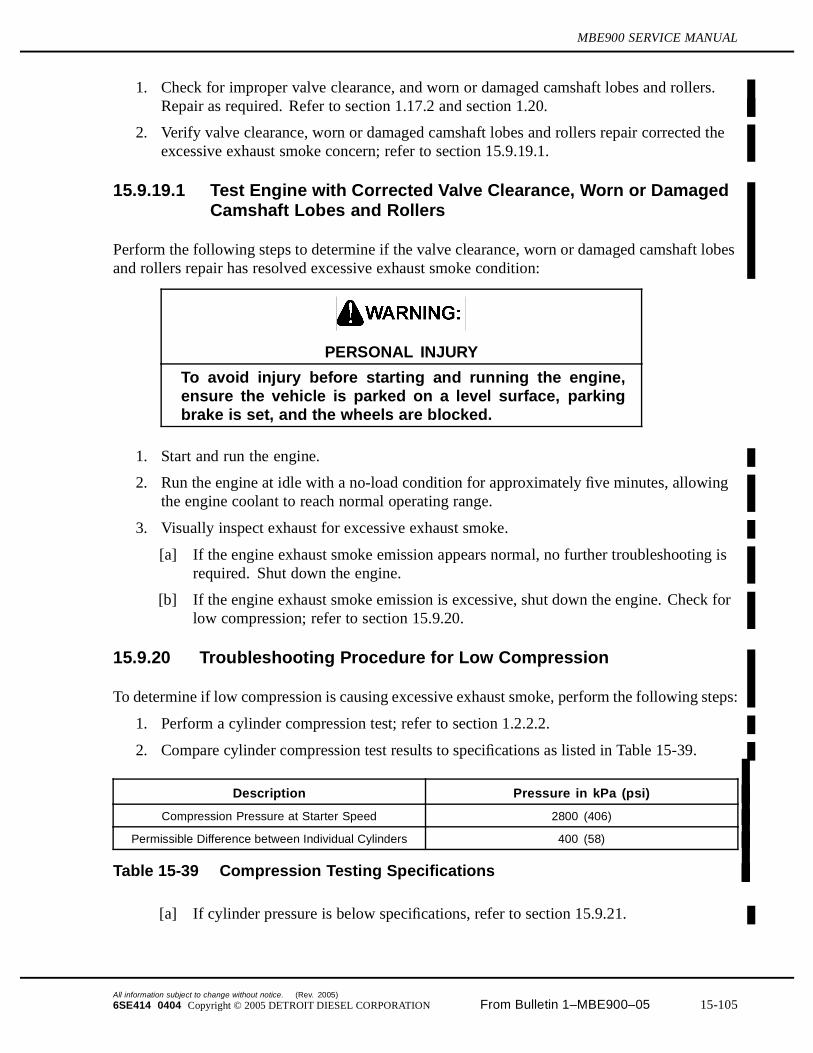
MBE900 SERVICE MANUAL
1. Check for improper valve clearance, and worn or damaged camshaft lobes and rollers.Repair as required. Refer to section 1.17.2 and section 1.20.
2. Verify valve clearance, worn or damaged camshaft lobes and rollers repair corrected theexcessive exhaust smoke concern; refer to section 15.9.19.1.
15.9.19.1 Test Engine with Corrected Valve Clearance, Worn or DamagedCamshaft Lobes and Rollers
Perform the following steps to determine if the valve clearance, worn or damaged camshaft lobesand rollers repair has resolved excessive exhaust smoke condition:
PERSONAL INJURY
To avoid injury before starting and running the engine,ensure the vehicle is parked on a level surface, parkingbrake is set, and the wheels are blocked.
1. Start and run the engine.
2. Run the engine at idle with a no-load condition for approximately five minutes, allowingthe engine coolant to reach normal operating range.
3. Visually inspect exhaust for excessive exhaust smoke.
[a] If the engine exhaust smoke emission appears normal, no further troubleshooting isrequired. Shut down the engine.
[b] If the engine exhaust smoke emission is excessive, shut down the engine. Check forlow compression; refer to section 15.9.20.
15.9.20 Troubleshooting Procedure for Low Compression
To determine if low compression is causing excessive exhaust smoke, perform the following steps:
1. Perform a cylinder compression test; refer to section 1.2.2.2.
2. Compare cylinder compression test results to specifications as listed in Table 15-39.
Description Pressure in kPa (psi)
Compression Pressure at Starter Speed 2800 (406)
Permissible Difference between Individual Cylinders 400 (58)
Table 15-39 Compression Testing Specifications
[a] If cylinder pressure is below specifications, refer to section 15.9.21.
All information subject to change without notice. (Rev. 2005)
6SE414 0404 Copyright © 2005 DETROIT DIESEL CORPORATION From Bulletin 1–MBE900–05 15-105
15.9 EXCESSIVE EXHAUST SMOKE (BLACK OR GRAY)
[b] If cylinder pressure is within specifications, call Detroit Diesel Customer SupportCenter at 313-592-5800.
15.9.21 Low Compression Repair
Perform the following steps for low compression repair.
1. Remove cylinder head; refer to section 1.2.1.
2. Inspect the cylinder head for worn or damaged valves; refer to section 1.17.
3. Replace damaged valves; refer to section 1.17.5.
4. Inspect the cylinder kit components for worn or damaged liners, pistons; or piston rings.
5. Verify repairs made to cylinder head valve(s) or cylinder kit components have correctedthe excessive exhaust smoke concern; refer to section 15.9.21.1.
15.9.21.1 Test Engine with Repaired Cylinder Head Valve(s), and CylinderKit
To determine if the cylinder head valve and cylinder kit repair resolved excessive exhaust smoke,perform the following steps:
PERSONAL INJURY
To avoid injury before starting and running the engine,ensure the vehicle is parked on a level surface, parkingbrake is set, and the wheels are blocked.
1. Attempt to start and run the engine, if the engine starts and runs without excessive exhaustsmoke, no further troubleshooting is required. Shut down the engine.
2. If the engine continues to have excessive exhaust smoke, call the Detroit Diesel CustomerSupport Center at 313-592-5800.
(Rev. 2005) All information subject to change without notice.
15-106 From Bulletin 1–MBE900–05 6SE414 0404 Copyright © 2005 DETROIT DIESEL CORPORATION

MBE900 SERVICE MANUAL
15.10 EXCESSIVE BLUE SMOKE
There are several causes for excessive blue exhaust smoke. These probable causes are:
Miscalibrated Dipstick Improper Grade of Lubricating Oil Defective Turbocharger Worn or Damaged Intake/Exhaust Valve or Cylinder Kit
15.10.1 Troubleshooting Procedure for Miscalibrated Dipstick
To determine if an overfilled crankcase is causing the excessive blue smoke, perform thefollowing:
1. Ensure the vehicle is parked on level ground.
2. Drain the oil pan. Refill oil pan to the proper capacity. Refer to section 13.1.4.
[a] If a calibration check indicates that the oil level is off by more than 2 mm (0.079 in.),contact Detroit Diesel Customer Support Center at 313-592-5800.
[b] Verify that the correct oil level has eliminated the excessive blue smoke concern;refer to section 15.10.2.
15.10.2 Test the Engine with the Correct Oil Level
Perform the following to determine if the correct oil level resolved the excessive blue smokecondition:
PERSONAL INJURY
To avoid injury before starting and running the engine,ensure the vehicle is parked on a level surface, parkingbrake is set, and the wheels are blocked.
1. Start and run the engine.
2. Run the engine at idle under no-load conditions for approximately five minutes, allowingthe engine coolant to reach normal operating range, approximately 88-96°C (190-205°F).
3. Visually inspect exhaust for excessive blue smoke.
[a] If the engine smoke emission appears normal, no further troubleshooting is required.Shut down the engine.
[b] If the engine exhaust smoke is excessively blue, shut down the engine.Refer to section15.10.3
All information subject to change without notice. (Rev. 2005)
6SE414 0404 Copyright © 2005 DETROIT DIESEL CORPORATION From Bulletin 1–MBE900–05 15-107
15.10 EXCESSIVE BLUE SMOKE
15.10.3 Troubleshooting Procedure for Improper Grade of Lubricating Oil
To determine if an improper grade of lubricating oil is causing excessive blue smoke, performthe following:
1. Verify that the proper grade of lubricating oil is being used in the engine.
2. See DDC publication Lubricating Oil, Fuel, and Filters (7SE270) for oil specifications.
3. If the oil meets specifications, check for defective turbocharger; refer to section 15.10.5.
4. If the oil did not meet specifications, resolve improper grade of oil; refer to section 15.10.4.See DDC publication Lubricating Oil, Fuel, and Filters (7SE270) for oil specifications.
15.10.4 Improper Grade of Lubricating Oil Resolution
Perform the following steps to resolve the improper grade of lubricating oil:
1. Drain the oil pan and filters. Dispose of oil properly.
2. Refill the engine oil pan with recommended oil. See DDC publication Lubricating Oil,Fuel, and Filters (7SE270) for oil specifications.
3. Verify the oil resolution corrected the excessive blue smoke condition; refer to section15.10.4.1.
15.10.4.1 Test Engine with New Lubricating Oil
Perform the following to determine if the new oil level resolved the excessive blue smokecondition:
PERSONAL INJURY
To avoid injury before starting and running the engine,ensure the vehicle is parked on a level surface, parkingbrake is set, and the wheels are blocked.
1. Start and run the engine.
2. Run the engine at idle under no-load conditions for approximately five minutes, allowingthe engine coolant to reach normal operating range, approximately 88-96°C (190-205°F).
3. Visually inspect exhaust for excessive blue smoke.
[a] If the engine smoke emission appears normal, no further troubleshooting is required.Shut down the engine.
[b] If the engine exhaust smoke is excessively blue, shut down the engine.Refer to section 15.10.5.
(Rev. 2005) All information subject to change without notice.
15-108 From Bulletin 1–MBE900–05 6SE414 0404 Copyright © 2005 DETROIT DIESEL CORPORATION
MBE900 SERVICE MANUAL
15.10.5 Troubleshooting Procedure for a Defective Turbocharger
To determine if a defective turbocharger is causing excessive blue exhaust smoke, perform thefollowing:
1. Remove the charge air cooler inlet duct connected between the turbocharger and chargeair cooler.
2. Visually inspect the compressor inlet side of the turbocharger.
[a] If excessive engine lube oil is present, replace the turbocharger refer to section 6.4.2.
[b] Verify replacing the turbocharger corrected the excessive blue smokeconcern; refer to section 15.10.5.1.
15.10.5.1 Test Engine with Replaced Turbocharger
Perform the following steps to determine if a replaced turbocharger has resolved the excessiveblue exhaust smoke condition:
PERSONAL INJURY
To avoid injury before starting and running the engine,ensure the vehicle is parked on a level surface, parkingbrake is set, and the wheels are blocked.
1. Start and run the engine.
2. Run the engine at idle speed with a no-load condition for approximately five minutes,allowing the engine coolant to reach normal operating range, approximately 88-96°C(190-205°F).
3. Visually inspect the exhaust for excessive blue smoke.
[a] If the engine exhaust smoke emission appears normal, no further troubleshooting isrequired. Shut down the engine.
[b] If the engine exhaust smoke is excessively blue, shut down the engine. Check forworn or damaged valves or cylinder kit; refer to section 15.10.6.
15.10.6 Troubleshooting Procedure for a Worn or DamagedIntake/Exhaust Valve or Cylinder Kit
To determine if a worn or damaged cylinder kit is causing excessive blue exhaust smoke, performthe following:
1. Move the vehicle requiring testing to the chassis dynamometer; refer to OEM guidelines.
2. Disconnect and remove the air compressor; refer to section 10.1.1.
All information subject to change without notice. (Rev. 2005)
6SE414 0404 Copyright © 2005 DETROIT DIESEL CORPORATION From Bulletin 1–MBE900–05 15-109
15.10 EXCESSIVE BLUE SMOKE
PERSONAL INJURY
To avoid injury before starting and running the engine,ensure the vehicle is parked on a level surface, parkingbrake is set, and the wheels are blocked.
3. Start the engine.
4. Run the engine and bring the engine coolant temperature to normal operating range,approximately 88-96°C (190-205°F).
5. Run the vehicle to full load and rated speed.
6. Attach a manometer calibrated to read pressure in kPa or inches of H2O, to the oil dipstick
opening.
7. Measure and record crankcase pressure.
8. Shut down the engine.
9. Remove the vehicle from the chassis dynamometer.
10. Review the crankcase pressure test.
[a] If the crankcase pressure was greater than 0.62 kPa (2.5 in. H2O), refer to section
15.10.7.
[b] If the crankcase pressure was less than 0.62 kPa (2.5 in. H2O), perform a cylinder
compression test; refer to section 1.2.2.2.
11. Compare the cylinder compression test results to specifications. Refer to section 1.2.2.2and specifications listed in Table 1-10.
[a] If cylinder pressure is below specifications, refer to section 15.10.7.
[b] If cylinder pressure is within specifications, call Detroit Diesel Customer SupportCenter at 313-592-5800.
15.10.7 Worn or Damaged Intake/Exhaust Valve or Cylinder Kit Repair
Perform the following steps for worn or damaged intake/exhaust valves or a cylinder kit:
1. Remove the cylinder head; refer to section 1.2.1.
2. Inspect the cylinder head for worn or damaged valves and worn or damaged valve stemseals; refer to section 1.17.
3. Inspect the cylinder kit components for worn or damaged liners, pistons or piston rings;refer to section 1.15.
4. Verify repair to cylinder valve(s) or cylinder kit components; refer to section 15.10.7.1.
(Rev. 2005) All information subject to change without notice.
15-110 From Bulletin 1–MBE900–05 6SE414 0404 Copyright © 2005 DETROIT DIESEL CORPORATION

MBE900 SERVICE MANUAL
15.10.7.1 Test Engine with Repairs Made to Correct Worn or DamagedIntake/Exhaust Valve or Cylinder Kit
Perform the following to determine if the repaired intake/exhaust valve or cylinder kit hasresolved the excessive crankcase pressure:
PERSONAL INJURY
To avoid injury before starting and running the engine,ensure the vehicle is parked on a level surface, parkingbrake is set, and the wheels are blocked.
1. Start the engine.
2. Run the engine and bring the engine coolant temperature to normal operating range,approximately 88-96°C (190-205°F).
3. Run the vehicle to full load and rated speed.
4. Visually inspect exhaust for excessive blue smoke.
[a] If the engine exhaust smoke emission appears normal for a rebuilt engine, no furthertroubleshooting is required. Shut down the engine.
[b] If the engine exhaust smoke emission is excessively blue, shut down the engine. Callthe Detroit Diesel Customer Support Center at 313-592-5800.
All information subject to change without notice. (Rev. 2005)
6SE414 0404 Copyright © 2005 DETROIT DIESEL CORPORATION From Bulletin 1–MBE900–05 15-111
15.11 EXCESSIVE WHITE SMOKE
15.11 EXCESSIVE WHITE SMOKE
There are several causes for excessive white exhaust smoke. These probable causes are:
Faulty DDEC-ECU Faulty Turbocharger Boost Sensor Malfunctioning Air Intake (Grid) Preheater Defective Fuel Pump Aerated Fuel Improper Grade of Fuel Faulty Turbocharger Control Unit Restricted or Cracked Charge Air Cooler Faulty Fuel Nozzle Holder Improper Valve Clearance, Worn or Damaged Camshaft Lobes and Rollers Low Cylinder Compression
15.11.1 Troubleshooting Procedure for Faulty DDEC-ECU
To determine if a faulty DDEC-ECU is causing excessive white smoke, perform the following:
1. Check for faulty DDEC-ECU. Refer to DDC publication MBE Troubleshooting Guide(6SE422) and SID 233.
2. Replace the faulty DDEC-ECU; refer to section 2.5.
3. Verify DDEC-ECU replacement; refer to section 15.11.2.
15.11.2 Test the Engine with Replaced DDEC-ECU
Perform the following to determine if the replaced DDEC-ECU has resolved the excessive whitesmoke:
PERSONAL INJURY
To avoid injury before starting and running the engine,ensure the vehicle is parked on a level surface, parkingbrake is set, and the wheels are blocked.
1. Start and run the engine.
2. Run the engine at idle with a no-load condition for approximately five minutes, allowingthe engine coolant to reach normal operating range.
3. Visually inspect the exhaust for excessive white smoke.
[a] If the engine exhaust emission appears normal, no further troubleshooting is required.Shut down the engine.
(Rev. 2005) All information subject to change without notice.
15-112 From Bulletin 1–MBE900–05 6SE414 0404 Copyright © 2005 DETROIT DIESEL CORPORATION
MBE900 SERVICE MANUAL
[b] If the engine exhaust emission is excessively white, shut down the engine.Refer to section 15.11.3.
15.11.3 Faulty Turbocharger Boost Sensor
To determine if a faulty turbocharger boost sensor is causing excessive white smoke, performthe following:
1. Check for faulty turbocharger boost sensor. Refer to DDC publication MBETroubleshooting Guide (6SE422) and PID 102.
2. Resolve the faulty turbocharger boost sensor; refer to section 15.11.4.
15.11.4 Turbocharger Boost Sensor Resolution
Perform the following steps to resolve a faulty turbocharger boost sensor:
1. Disconnect harness connection from turbocharger boost sensor and remove two boltssecuring the boost sensor to the air intake manifold. Discard sensor.
2. Secure the turbocharger boost sensor to the air intake manifold with two bolts. Torquebolts to 11 N·m (96 lb·in.).
3. Connect the harness connector to the boost sensor.
4. Verify the turbocharger boost sensor resolution; refer to section 15.11.4.1.
15.11.4.1 Test Engine with Replace Turbocharger Boost Sensor
Perform the following to determine if replacing the turbocharger boost sensor corrected theexcessive white smoke condition:
PERSONAL INJURY
To avoid injury before starting and running the engine,ensure the vehicle is parked on a level surface, parkingbrake is set, and the wheels are blocked.
1. Start the engine.
2. Run the engine speed to full load.
3. Visually inspect the exhaust for excessive white smoke.
[a] If the engine exhaust emission appears normal, no further troubleshooting is required.Shut down the engine.
[b] If the engine exhaust emission is excessive, shut down the engine, check for amalfunctioning air intake (grid) preheater. Refer to section 15.11.5.
All information subject to change without notice. (Rev. 2005)
6SE414 0404 Copyright © 2005 DETROIT DIESEL CORPORATION From Bulletin 1–MBE900–05 15-113
15.11 EXCESSIVE WHITE SMOKE
15.11.5 Troubleshooting Procedure for a Malfunctioning Air Intake (Grid)Preheater
To determine if a malfunctioning air intake (grid) preheater is causing the excessive white smoke,perform the following steps:
1. Check the operation of the air intake (grid) preheater. Refer to DDC publication MBETroubleshooting Guide (6SE422) and PID 45.
[a] If heater operates correctly; check for a defective fuel pump. Refer to section 15.11.6.
[b] If heater does not operate correctly, replace air intake (grid) preheater; refer to section6.1.1.
2. Verify replacing the air intake (grid) preheater resolved the excessive white smokecondition; refer to section 15.11.5.1.
15.11.5.1 Test the Engine with Replaced Air Intake (Grid) Preheater
Perform the following to determine if replacing the air intake (grid) preheater corrected theexcessive white smoke condition:
PERSONAL INJURY
To avoid injury before starting and running the engine,ensure the vehicle is parked on a level surface, parkingbrake is set, and the wheels are blocked.
1. Start the engine.
2. Run the engine speed to full load.
3. Visually inspect the exhaust for excessive white smoke.
[a] If the engine exhaust emission appears normal, no further troubleshooting is required.Shut down the engine.
[b] If the engine exhaust emission is excessive, shut down the engine, check for adefective fuel pump. Refer to section 15.11.6.
15.11.6 Troubleshooting Procedure for a Defective Fuel Pump
To determine if the fuel pump is causing excessive white smoke, perform the following to checkfuel intake pressure upstream of fuel pump. Refer to section 15.3.5.
1. If the pressure at idle speed (600-650 rpm) is in the normal range of -0.09 to -0.12 bar(-1.3 to -1.7 psi [-9 to -12 kPa]), check for aerated fuel. Refer to section 15.11.8.
2. If the pressure at idle speed (600-650 rpm) is greater than -0.09 to -0.12 bar (-1.3 to -1.7psi [-9 to -12 kPa]); refer to Table 15-36.
(Rev. 2005) All information subject to change without notice.
15-114 From Bulletin 1–MBE900–05 6SE414 0404 Copyright © 2005 DETROIT DIESEL CORPORATION
MBE900 SERVICE MANUAL
3. If the pressure at idle speed (600-650 rpm) is less than -0.09 to -0.12 bar (-1.3 to -1.7psi [-9 to -12 kPa]); refer to Table 15-35
4. If a no pressure reading is observed, replace the fuel pump; refer to section 2.15.1.
15.11.7 Replace Faulty Fuel Pump
Perform the following steps for the replacement of the fuel pump:
1. Replace the fuel pump; refer to section 2.15.1.
2. Test the engine to determine if the white smoke problem was resolved; refer to section15.11.7.1.
15.11.7.1 Engine Test with Replaced Fuel Pump
To determine if the replaced fuel pump resolved excessive white smoke difficulty, perform thefollowing steps:
PERSONAL INJURY
To avoid injury before starting and running the engine,ensure the vehicle is parked on a level surface, parkingbrake is set, and the wheels are blocked.
1. Start and run the engine, if no white smoke is visible, no further troubleshooting isrequired. Shut down the engine.
2. If white smoke is visible, check for aerated fuel; refer to section 15.11.8
15.11.8 Troubleshooting Procedure for Aerated Fuel
To determine if aerated fuel is causing excessive white smoke, perform the following steps:
1. Disconnect the fuel line return hose from the fitting located at the fuel tank; refer to OEMguidelines.
2. Place the open end of the fuel line into a suitable container.
All information subject to change without notice. (Rev. 2005)
6SE414 0404 Copyright © 2005 DETROIT DIESEL CORPORATION From Bulletin 1–MBE900–05 15-115
15.11 EXCESSIVE WHITE SMOKE
PERSONAL INJURY
To avoid injury before starting and running the engine,ensure the vehicle is parked on a level surface, parkingbrake is set, and the wheels are blocked.
3. Start and run the engine.
4. Operate the engine at 1000 rpm.
5. Visually check to see if air bubbles are rising to the surface of the fuel within the container.
[a] If air bubbles are present, shut down the engine; refer to section 15.11.9.
[b] If air bubbles are not present, shut down the engine, check for improper grade offuel; refer to section 15.11.10.
15.11.9 Aerated Fuel Resolution
Perform the following steps to resolve aerated fuel:
1. Tighten all fuel line connections between fuel tank and fuel pump; refer to OEMguidelines.
2. Visually inspect all fuel lines between fuel tank and fuel pump for leaks.
3. Repair damaged components as required; refer to OEM guidelines.
4. Verify aerated fuel resolution; refer to section 15.11.9.1.
15.11.9.1 Test the Engine with Aerated Fuel Resolution
Perform the following to determine if aerated fuel resolution resolved excessive white smokecondition:
PERSONAL INJURY
To avoid injury before starting and running the engine,ensure the vehicle is parked on a level surface, parkingbrake is set, and the wheels are blocked.
1. Start and run the engine.
2. Run the engine at idle with a no-load condition for approximately five minutes, allowingthe engine coolant to reach normal operating range.
3. Visually inspect exhaust for excessive white smoke.
(Rev. 2005) All information subject to change without notice.
15-116 From Bulletin 1–MBE900–05 6SE414 0404 Copyright © 2005 DETROIT DIESEL CORPORATION

MBE900 SERVICE MANUAL
[a] If the engine exhaust emission appears normal, no further troubleshooting is required.Shut down the engine.
[b] If the engine exhaust emission is excessively white, shut down the engine. Checkfor improper grade of fuel; refer to section 15.11.10.
15.11.10 Troubleshooting Procedure for Improper Grade of Fuel
To determine if an improper grade of fuel is causing the excessive white smoke, perform thefollowing:
1. Acquire a fuel sample from the vehicle fuel tank(s).
2. Submit fuel sample for an ASTM test analysis.
[a] If the fuel meets specifications, check for a faulty turbocharger control unit;refer to section 15.11.12.
[b] If the fuel did not meet specifications, resolve improper grade of fuel; refer to section15.11.11 and DDC publication Lubricating Oil, Fuel, and Filters (7SE270).
15.11.11 Improper Grade of Fuel Resolution
Perform the following steps to resolve the improper grade of fuel:
1. Drain the fuel tanks, refer to OEM guidelines, and dispose of properly.
2. Refill the fuel tanks with new fuel having a cetane number greater than 45 and cetaneindex greater than 40.
3. Verify fuel resolution eliminated the excessive exhaust smoke condition; refer to section15.11.11.1.
15.11.11.1 Test the Engine with New Fuel
Perform the following steps to determine if the fuel refill resolved the excessive white smokecondition:
PERSONAL INJURY
To avoid injury before starting and running the engine,ensure the vehicle is parked on a level surface, parkingbrake is set, and the wheels are blocked.
1. Start and run the engine.
2. Run the engine at idle under no-load conditions for approximately five minutes, allowingthe engine coolant to reach normal operating range, approximately 88-96°C (190-205°F).
3. Visually inspect exhaust for excessive smoke.
All information subject to change without notice. (Rev. 2005)
6SE414 0404 Copyright © 2005 DETROIT DIESEL CORPORATION From Bulletin 1–MBE900–05 15-117
15.11 EXCESSIVE WHITE SMOKE
[a] If the engine smoke emission appears normal, no further troubleshooting is required.Shut down the engine.
[b] If the engine exhaust smoke is excessively white, shut down the engine. Check theturbocharger control unit; refer to section 15.11.12.
15.11.12 Troubleshooting Procedure for Faulty Turbocharger Control Unit
To determine if an improper turbocharger control unit is causing excessive white smoke, inspectthe turbocharger control unit for a leaking diaphragm. Refer to section 6.4.1.
1. If the control unit diaphragm is leaking replace the turbocharger; refer to section 6.4.2.
2. Verify the replacement of the turbocharger and unit control corrected the excessive whitesmoke condition; refer to section 15.11.12.1.
15.11.12.1 Test Engine with Replace Turbocharger and Control Unit
Perform the following to determine if replacing the turbocharger and control unit corrected theexcessive white smoke condition:
PERSONAL INJURY
To avoid injury before starting and running the engine,ensure the vehicle is parked on a level surface, parkingbrake is set, and the wheels are blocked.
1. Start the engine.
2. Run the engine speed to full load.
3. Visually inspect the exhaust for excessive white smoke.
[a] If the engine exhaust emission appears normal, no further troubleshooting is required.Shut down the engine.
[b] If the engine exhaust emission is excessive, shut down the engine, check for arestricted or cracked charge air cooler. Refer to section 15.11.13.
15.11.13 Troubleshooting Procedure for a Restricted or Cracked ChargeAir Cooler
To determine if a charge air cooler is causing excessive exhaust smoke, perform the following:
(Rev. 2005) All information subject to change without notice.
15-118 From Bulletin 1–MBE900–05 6SE414 0404 Copyright © 2005 DETROIT DIESEL CORPORATION
MBE900 SERVICE MANUAL
NOTICE:
To avoid engine damage, follow the installation instructionsprovided with the air-to-air charge air cooler test kit.
1. Visually inspect the core, tanks, and welds for cracks and holes. If cooler fails visualinspection, replace the charge air cooler; refer to section15.11.14.
2. Pressure test the charge air cooler. Refer to section 15.9.3.1.
3. Evaluate the results from pressure testing the charge air cooler.
[a] If the pressure drop is 34 kPa (5 psi) or less in 15 seconds the cooler is good. Checkfor faulty fuel injection nozzle; refer to section 15.11.15.
[b] If the pressure drop is greater than 34 kPa (5 psi) in 15 seconds, replace the charge aircooler; refer to section 15.11.14.
15.11.14 Charge Air Cooler Replacement
Perform the following steps to replace the charge air cooler:
1. Replace the charge air cooler; refer to OEM guidelines.
2. Verify that the replacement of the charge air cooler eliminated the excessive white exhaustsmoke; refer to section 15.11.14.1.
15.11.14.1 Test the Engine with a Replaced Charge Air Cooler
To determine if the replaced charge air cooler resolved the excessive white exhaust smokecondition, perform the following:
PERSONAL INJURY
To avoid injury before starting and running the engine,ensure the vehicle is parked on a level surface, parkingbrake is set, and the wheels are blocked.
1. Start and run the engine.
2. Run the engine at idle with a no-load condition for approximately five minutes, allowingthe engine coolant to reach normal operating range, approximately 88-96°C (190-205°F).
3. Visually inspect exhaust for excessive white smoke.
[a] If the engine exhaust emission appears normal, no further troubleshooting is required.Shut down the engine.
[b] If the engine exhaust emission is excessively white, shut down the engine. Check fora faulty fuel injection nozzle holder; refer to section 15.11.15.
All information subject to change without notice. (Rev. 2005)
6SE414 0404 Copyright © 2005 DETROIT DIESEL CORPORATION From Bulletin 1–MBE900–05 15-119
15.11 EXCESSIVE WHITE SMOKE
15.11.15 Troubleshooting for a Faulty Fuel Injection Nozzle Holder
To determine if a faulty fuel injection nozzle holder is causing excessive white smoke, performthe following:
1. Check for faulty fuel injection nozzle holder; perform “Flow Test at Nozzle Holder”.Refer to section 15.3.3.
2. Repair or replace the faulty fuel injection nozzle holder; refer to section 2.3.1.
3. Verify fuel injection nozzle holder repair or replacement; refer to section 15.11.15.1.
15.11.15.1 Test the Engine with Repaired Fuel Injection Nozzle Holder
To determine if a faulty fuel injector nozzle holder is causing excessive white smoke, performthe following:
PERSONAL INJURY
To avoid injury before starting and running the engine,ensure the vehicle is parked on a level surface, parkingbrake is set, and the wheels are blocked.
1. Start and run the engine.
2. Run the engine at idle with a no-load condition for approximately five minutes, allowingthe engine coolant to reach normal operating range, approximately 88-96°C (190-205°F).
3. Visually inspect exhaust for excessive white smoke.
[a] If the engine exhaust emission appears normal, no further troubleshooting is required.Shut down the engine.
[b] If the engine exhaust emission is excessively white, shut down the engine. Check forimproper valve clearance or damaged camshaft lobes and rollers; refer to section15.11.16.
15.11.16 Troubleshooting Procedure for Improper Valve Clearance, Wornor Damaged Camshaft Lobes and Rollers
To determine if an improper valve clearance, worn or damaged camshaft lobes or rollers arecausing excessive white exhaust smoke, perform the following:
1. Check for improper valve clearance, and worn or damaged camshaft lobes and rollers.Repair as required. Refer to section 1.17.2 and section 1.20.1.1.
2. Verify valve clearance, worn or damaged camshaft lobes and rollers repair corrected theexcessive white exhaust smoke concern; refer to section 15.11.16.1.
(Rev. 2005) All information subject to change without notice.
15-120 From Bulletin 1–MBE900–05 6SE414 0404 Copyright © 2005 DETROIT DIESEL CORPORATION
MBE900 SERVICE MANUAL
15.11.16.1 Test Engine with Corrected Valve Clearance, Worn or DamagedCamshaft Lobes and Rollers
Perform the following steps to determine if the valve clearance, worn or damaged camshaft lobesand rollers repair has resolved excessive white exhaust smoke condition:
PERSONAL INJURY
To avoid injury before starting and running the engine,ensure the vehicle is parked on a level surface, parkingbrake is set, and the wheels are blocked.
1. Start and run the engine.
2. Run the engine at idle with a no-load condition for approximately five minutes, allowingthe engine coolant to reach normal operating range.
3. Visually inspect exhaust for excessive white exhaust smoke.
[a] If the engine exhaust smoke emission appears normal, no further troubleshooting isrequired. Shut down the engine.
[b] If the engine exhaust smoke emission is excessive, shut down the engine. Check forlow cylinder compression; refer to section 15.11.17.
15.11.17 Troubleshooting for Low Cylinder Compression
To determine if low compression is causing excessive white smoke condition, perform thefollowing steps:
1. Perform a cylinder compression test;refer to section 1.2.2.2.
2. Compare cylinder compression test results to specifications as listed in Table 15-40.
Description Pressure in kPa (psi)
Compression Pressure at Starter Speed 2800 (406)
Permissible Difference between Individual Cylinders 400 (58)
Table 15-40 Compression Testing Specifications
[a] If cylinder pressure is below specifications, refer to section 15.5.28.
[b] If cylinder pressure is within specifications, call Detroit Diesel Customer SupportCenter at 313-592-5800.
All information subject to change without notice. (Rev. 2005)
6SE414 0404 Copyright © 2005 DETROIT DIESEL CORPORATION From Bulletin 1–MBE900–05 15-121
15.12 ROUGH RUNNING OR STALLING
15.12 ROUGH RUNNING OR STALLING
There are several causes for rough running or stalling. These probable causes are:
Low Battery Voltage Aerated Fuel Insufficient Fuel Flow
15.12.1 Troubleshooting Procedure for Low Battery Voltage
To determine if a weak battery is causing rough running or stalling, perform the following steps:
PERSONAL INJURY
To avoid injury before starting and running the engine,ensure the vehicle is parked on a level surface, parkingbrake is set, and the wheels are blocked.
1. Start and run the engine.
2. Measure the battery voltage; refer to OEM guidelines.
[a] If the battery voltage is greater than or equal to 10.5 volts, check for aerated fuel;refer to section 15.12.3.
[b] If the battery voltage is less than 10.5 volts, replace the battery; refer to section15.12.2.
15.12.2 Battery Replacement
Perform the following steps for battery replacement:
1. Remove and replace the battery; refer to OEM guidelines.
2. Verify battery replacement; refer to section 15.12.2.1.
15.12.2.1 Test Engine with Replaced Battery
Perform the following steps to determine if the battery replacement resolved the concern:
(Rev. 2005) All information subject to change without notice.
15-122 From Bulletin 1–MBE900–05 6SE414 0404 Copyright © 2005 DETROIT DIESEL CORPORATION
MBE900 SERVICE MANUAL
PERSONAL INJURY
To avoid injury before starting and running the engine,ensure the vehicle is parked on a level surface, parkingbrake is set, and the wheels are blocked.
1. Start and run the engine.
2. Run the engine at idle with a no-load condition for approximately five minutes, allowingthe engine coolant to reach normal operating range, 88-96°C (190-205°F).
[a] If the engine is not running rough or stalling, no further troubleshooting is required.Shut down the engine.
[b] If the engine is running rough or stalling, shut down the engine. Check for aeratedfuel; refer to section 15.12.3.
15.12.3 Troubleshooting Procedure for Aerated Fuel
To determine if aerated fuel is causing rough running or stalling, perform the following steps:
1. Disconnect the fuel line return hose from the fitting at the fuel tank; refer to OEMguidelines.
2. Place the open end of the fuel line into a suitable container.
PERSONAL INJURY
To avoid injury before starting and running the engine,ensure the vehicle is parked on a level surface, parkingbrake is set, and the wheels are blocked.
3. Start and run the engine.
4. Operate the engine at 1000 rpm.
5. Visually check to see if air bubbles are rising to the surface of the fuel within the container.
[a] If air bubbles are present, shut down the engine; refer to section 15.12.4.
[b] If air bubbles are not present, shut down the engine. Check for high fuel temperaturereturn, which would be an indication of insufficient fuel flow.
15.12.4 Aerated Fuel Resolution
Perform the following steps to resolve aerated fuel:
All information subject to change without notice. (Rev. 2005)
6SE414 0404 Copyright © 2005 DETROIT DIESEL CORPORATION From Bulletin 1–MBE900–05 15-123
15.12 ROUGH RUNNING OR STALLING
1. Tighten all fuel line connections between fuel tank and fuel pump; refer to OEMguidelines.
2. Visually inspect all fuel lines for leaks between fuel tank and fuel pump.
3. Repair damaged components as required; refer to OEM guidelines.
4. Verify aerated fuel resolution; refer to section 15.12.4.1.
15.12.4.1 Test the Engine with Aerated Fuel Resolution
Perform the following to determine if aerated fuel resolution has resolved rough running orstalling condition:
PERSONAL INJURY
To avoid injury before starting and running the engine,ensure the vehicle is parked on a level surface, parkingbrake is set, and the wheels are blocked.
1. Start and run the engine.
2. Run the engine at idle with a no-load condition for approximately five minutes, allowingthe engine coolant to reach normal operating range.
3. Test for rough running condition.
[a] If the engine appears normal, no further troubleshooting is required. Shut downthe engine.
[b] If the engine is still running rough, shut down the engine. Check for insufficient fuelflow. Refer to section 15.12.5.
15.12.5 Troubleshooting Procedure for Insufficient Fuel Flow
To determine if insufficient fuel flow is causing rough running or stalling, do the following steps:
1. Perform Fuel Flow Test #3 and measure the fuel return flow rate. Refer to section 15.3.4and see Figure 15-2.
2. Analyze the fuel flow test results.
[a] If the fuel rate is 0.9 L/min. (0.2 gal/min.) or more, no further troubleshooting isrequired. Contact Detroit Diesel Customer Support Center at 313-592-5800.
[b] If the fuel rate is less than 0.9 L/min. (0.2 gal/min.), resolve the insufficient fuelflow; refer to section 15.12.6.
(Rev. 2005) All information subject to change without notice.
15-124 From Bulletin 1–MBE900–05 6SE414 0404 Copyright © 2005 DETROIT DIESEL CORPORATION
MBE900 SERVICE MANUAL
15.12.6 Insufficient Fuel Flow Resolution
Perform the following steps to resolve the insufficient fuel flow:
1. Replace the fuel filter(s); refer to section 2.14.1.
NOTE:Always fill the filter(s) with clean fuel oil before installing. Turn the filter(s) until theycontact the gasket fully. Then turn them an additional two-thirds by hand.
2. Inspect the fuel lines for restrictions due to pinching, kinking, or other damage. If damageis found, repair as necessary; refer to OEM guidelines.
3. Inspect the fuel return check valve for restrictive movement.
4. Inspect the fuel pump drive assembly. If damage is found, repair as necessary;refer to section 2.15.
5. Verify repairs done to correct insufficient fuel flow; refer to section 15.12.6.1.
15.12.6.1 Test the Engine with Resolved Fuel Flow
Perform the following steps to determine if the fuel flow resolution resolved rough runningor stalling:
PERSONAL INJURY
To avoid injury before starting and running the engine,ensure the vehicle is parked on a level surface, parkingbrake is set, and the wheels are blocked.
1. Start and run the engine.
2. Run the engine at idle with a no-load capacity for approximately five minutes, allowingthe engine coolant to reach normal operating range, 88-96°C (190-205°F).
[a] If the engine is not running rough or stalling, no further troubleshooting is required.Shut down the engine.
[b] If the engine is running rough or stalling, shut down the engine. Contact DetroitDiesel Customer Support Center at 313-592-5800.
All information subject to change without notice. (Rev. 2005)
6SE414 0404 Copyright © 2005 DETROIT DIESEL CORPORATION From Bulletin 1–MBE900–05 15-125
15.13 LACK OF POWER
15.13 LACK OF POWER
There are several causes for lack of power. These probable causes are:
Aerated Fuel High Fuel Pressure High Fuel Temperature Return Faulty Overflow Valve Restricted Air Cleaner Element Restricted or Cracked Charge Air Cooler or Leaking Intake Manifold Faulty Exhaust System High Inlet Air Temperature Incorrect Camshaft Timing
15.13.1 Troubleshooting Procedure for Aerated Fuel
To determine if aerated fuel is causing lack of power, perform the following steps:
1. Test for aerated fuel.
2. Disconnect the fuel line return hose from the fitting located at the fuel tank; refer to OEMguidelines.
3. Place the open end of the fuel line into a suitable container.
PERSONAL INJURY
To avoid injury before starting and running the engine,ensure the vehicle is parked on a level surface, parkingbrake is set, and the wheels are blocked.
4. Start and run the engine.
5. Operate the engine at 1000 rpm.
6. Visually check to see if air bubbles are rising to the surface of the fuel that collects withinthe container.
[a] If air bubbles are not present, shut down the engine, check for high fuel pressure;refer to section 15.13.3.
[b] If air bubbles are present, shut down the engine; refer to section 15.13.2.
15.13.2 Aerated Fuel Resolution
Perform the following steps to resolve aerated fuel condition:
1. Tighten all fuel line connections between fuel tank and fuel pump; refer to OEMguidelines.
(Rev. 2005) All information subject to change without notice.
15-126 From Bulletin 1–MBE900–05 6SE414 0404 Copyright © 2005 DETROIT DIESEL CORPORATION
MBE900 SERVICE MANUAL
2. Visually inspect all fuel lines between fuel tank and fuel pump for leaks.
3. Repair damaged components as required; refer to OEM guidelines.
4. Verify aerated fuel resolution; refer to section 15.13.2.1.
15.13.2.1 Test the Engine with Aerated Fuel Resolution
Perform the following steps to determine if aerated fuel resolution has resolved lack of powercondition:
PERSONAL INJURY
To avoid injury before starting and running the engine,ensure the vehicle is parked on a level surface, parkingbrake is set, and the wheels are blocked.
1. Start and run the engine.
2. Run the engine at idle with a no-load condition for approximately five minutes, allowingthe engine coolant to reach normal operating range.
3. Test drive the vehicle to ensure lack of power has been resolved.
[a] If no lack of power occurred during the test drive, no further troubleshooting isrequired. Shut down the engine.
[b] If lack of power occurred during the test drive, shut down the engine. Check for highfuel pressure; refer to section 15.13.3.
15.13.3 Troubleshooting Procedure for High Fuel Pressure
To determine if high fuel pressure is causing a lack of power, perform the following steps:
All information subject to change without notice. (Rev. 2005)
6SE414 0404 Copyright © 2005 DETROIT DIESEL CORPORATION From Bulletin 1–MBE900–05 15-127
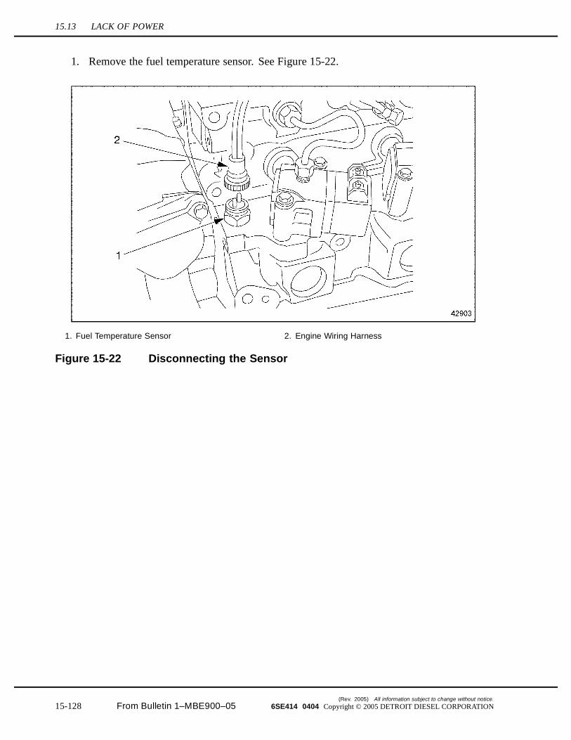
15.13 LACK OF POWER
1. Remove the fuel temperature sensor. See Figure 15-22.
1. Fuel Temperature Sensor 2. Engine Wiring Harness
Figure 15-22 Disconnecting the Sensor
(Rev. 2005) All information subject to change without notice.
15-128 From Bulletin 1–MBE900–05 6SE414 0404 Copyright © 2005 DETROIT DIESEL CORPORATION
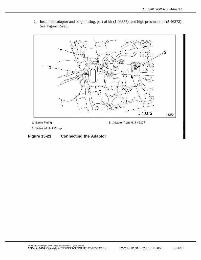
MBE900 SERVICE MANUAL
2. Install the adaptor and banjo fitting, part of kit (J-46377), and high pressure line (J-46372).See Figure 15-23.
1. Banjo Fitting 3. Adaptor from kit J-46377
2. Solenoid Unit Pump
Figure 15-23 Connecting the Adaptor
All information subject to change without notice. (Rev. 2005)
6SE414 0404 Copyright © 2005 DETROIT DIESEL CORPORATION From Bulletin 1–MBE900–05 15-129
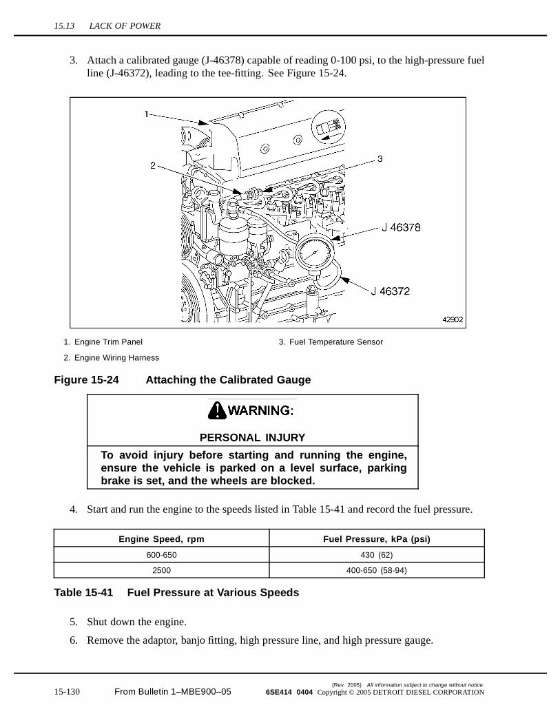
15.13 LACK OF POWER
3. Attach a calibrated gauge (J-46378) capable of reading 0-100 psi, to the high-pressure fuelline (J-46372), leading to the tee-fitting. See Figure 15-24.
1. Engine Trim Panel 3. Fuel Temperature Sensor
2. Engine Wiring Harness
Figure 15-24 Attaching the Calibrated Gauge
PERSONAL INJURY
To avoid injury before starting and running the engine,ensure the vehicle is parked on a level surface, parkingbrake is set, and the wheels are blocked.
4. Start and run the engine to the speeds listed in Table 15-41 and record the fuel pressure.
Engine Speed, rpm Fuel Pressure, kPa (psi)
600-650 430 (62)
2500 400-650 (58-94)
Table 15-41 Fuel Pressure at Various Speeds
5. Shut down the engine.
6. Remove the adaptor, banjo fitting, high pressure line, and high pressure gauge.
(Rev. 2005) All information subject to change without notice.
15-130 From Bulletin 1–MBE900–05 6SE414 0404 Copyright © 2005 DETROIT DIESEL CORPORATION

MBE900 SERVICE MANUAL
7. Reinstall the fuel temperature sensor.
8. Analyze the measure fuel pressure readings.
[a] If the fuel pressure is within specifications listed in Table 15-41, check for high fueltemperature return; refer to section 15.13.6.
[b] If the fuel pressure is greater than specifications listed in Table 15-41, refer to section15.13.5.
15.13.4 Troubleshooting Procedure for Faulty Overflow Valve
To determine if a faulty overflow valve is causing a lack of power, perform the following steps:
1. Run Fuel system Test #1: Downstream Pressure Test. Refer to section 15.3.2.
2. If Test #1 indicates faulty overflow valve, proceed to step 3.
3. Run fuel system Test #3: Flow Test – At Fuel Filter. Refer to section 15.3.4.
4. If the overflow valve is found to be faulty, replace the overflow valve. Refer to section15.13.5.
15.13.5 Overflow Valve Replacement
Perform the following steps to replace the overflow valve.
1. Remove the overflow valve from the fuel return line.
All information subject to change without notice. (Rev. 2005)
6SE414 0404 Copyright © 2005 DETROIT DIESEL CORPORATION From Bulletin 1–MBE900–05 15-131
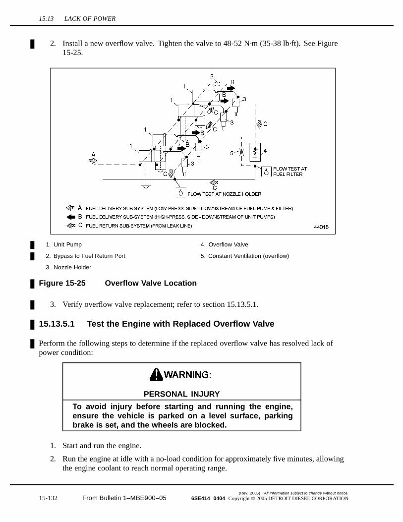
15.13 LACK OF POWER
2. Install a new overflow valve. Tighten the valve to 48-52 N·m (35-38 lb·ft). See Figure15-25.
1. Unit Pump 4. Overflow Valve
2. Bypass to Fuel Return Port 5. Constant Ventilation (overflow)
3. Nozzle Holder
Figure 15-25 Overflow Valve Location
3. Verify overflow valve replacement; refer to section 15.13.5.1.
15.13.5.1 Test the Engine with Replaced Overflow Valve
Perform the following steps to determine if the replaced overflow valve has resolved lack ofpower condition:
PERSONAL INJURY
To avoid injury before starting and running the engine,ensure the vehicle is parked on a level surface, parkingbrake is set, and the wheels are blocked.
1. Start and run the engine.
2. Run the engine at idle with a no-load condition for approximately five minutes, allowingthe engine coolant to reach normal operating range.
(Rev. 2005) All information subject to change without notice.
15-132 From Bulletin 1–MBE900–05 6SE414 0404 Copyright © 2005 DETROIT DIESEL CORPORATION

MBE900 SERVICE MANUAL
3. Test drive the vehicle to ensure lack of power has been resolved.
[a] If no lack of power occurred during the test drive, no further troubleshooting isrequired. Shut down the engine.
[b] If lack of power occurred during the test drive, shut down the engine. Check for highfuel temperature return; refer to section 15.13.6.
15.13.6 Troubleshooting Procedure for High Fuel Temperature Return
To determine if high fuel temperature return is causing lack of power, perform the following steps:
1. Test for high fuel temperature return.
2. Analyze the high fuel temperature test results.
[a] If the return fuel temperature is less than or equal to 60°C (140°F), check for aircleaner restriction; refer to section 15.13.8.
[b] If the return fuel temperature is greater than 60°C (140°F), resolve the high fueltemperature return condition; refer to section 15.13.7.
15.13.7 High Fuel Temperature Resolution
Perform the following steps to resolve high fuel temperature return:
1. Remove and replace fuel filter(s); refer to section 2.14.1.
2. Verify high fuel temperature repair; refer to section 15.13.7.1.
15.13.7.1 Test the Engine with Resolved High Fuel Temperature
Perform the following steps to determine if high fuel temperature repairs have resolved lackof power condition:
PERSONAL INJURY
To avoid injury before starting and running the engine,ensure the vehicle is parked on a level surface, parkingbrake is set, and the wheels are blocked.
1. Start and run the engine.
2. Test drive the vehicle to ensure lack of power has been resolved.
[a] If lack of power did not occur during the test drive, no further troubleshooting isrequired. Shut down the engine.
[b] If lack of occurred during the test drive, shut down the engine. Check for a restrictedair cleaner element; refer to section 15.13.8.
All information subject to change without notice. (Rev. 2005)
6SE414 0404 Copyright © 2005 DETROIT DIESEL CORPORATION From Bulletin 1–MBE900–05 15-133
15.13 LACK OF POWER
15.13.8 Troubleshooting Procedure for Restricted Air Cleaner Element
To determine if a restricted air cleaner element is causing lack of power, perform the followingsteps:
1. Remove the air filter element from the air cleaner container; refer to OEM guidelines.
2. Visually inspect the air cleaner element for damage or clogging.
[a] If no damage or clogging is found, check the charge air cooler; refer to section15.13.10.
[b] If damage or clogging is found, refer to section 15.13.9.
15.13.9 Air Filter Element Replacement
Perform the following steps to replace the air filter element:
1. Remove and replace the damaged or clogged air filter element; refer to OEM guidelines.
2. Verify air filter element replacement; refer to section 15.13.9.1.
15.13.9.1 Test the Engine with Replaced Air Filter Element
Perform the following steps to determine if the new air filter element has resolved lack of power:
PERSONAL INJURY
To avoid injury before starting and running the engine,ensure the vehicle is parked on a level surface, parkingbrake is set, and the wheels are blocked.
1. Start and run the engine.
2. Test drive the vehicle to ensure lack of power has been resolved.
[a] If lack of power did not occur during the test drive, no further troubleshooting isrequired. Shut down the engine.
[b] If lack of power occurred during the test drive, shut down the engine. Check thecharge air cooler; refer to section 15.13.10.
15.13.10 Troubleshooting Procedure for Restricted or Cracked ChargeAir Cooler
To determine if a restricted or cracked charge air cooler is causing lack of power, perform thefollowing steps:
(Rev. 2005) All information subject to change without notice.
15-134 From Bulletin 1–MBE900–05 6SE414 0404 Copyright © 2005 DETROIT DIESEL CORPORATION
MBE900 SERVICE MANUAL
NOTICE:
To avoid engine damage, follow the installation instructionsprovided with the air-to-air charge air cooler test kit.
1. Visually inspect the core, tanks, and welds for cracks and holes. If cooler fails visualinspection replace the charge air cooler; refer to section 15.13.11.
2. Pressure test the charge air cooler; refer to section 15.9.3.1.
3. Evaluate the results from pressure testing the charge air cooler.
[a] If the pressure drop is 34 kPa (5 psi) or less in 15 seconds, the cooler is good. Checkfor faulty air intake manifold; refer to section 15.13.12.
[b] If the pressure drop is greater than 34 kPa (5 psi) in 15 seconds, replace the charge aircooler; refer to section 15.13.11.
15.13.11 Charge Air Cooler Replacement
Perform the following steps to replace the charge air cooler:
1. Remove and replace the charge air cooler; refer to OEM guidelines.
2. Verify replacement of the charge air cooler; refer to section 15.13.12.1.
15.13.12 Troubleshooting Procedure for a Faulty Air Intake ManifoldGasket
Perform the following steps to troubleshoot a faulty air intake manifold gasket:
1. Remove the air intake manifold; refer to section 6.2.1.
2. Inspect the air intake manifold and gaskets.
3. Install the air intake manifold with new gaskets; refer to section 6.6.2.
4. Verify repair of the intake manifold; refer to section 15.13.12.1.
15.13.12.1 Test the Engine with Replaced Charge Air Cooler or Air IntakeManifold Gasket
To determine if the repairs resolved the lack of power condition, perform the following steps:
All information subject to change without notice. (Rev. 2005)
6SE414 0404 Copyright © 2005 DETROIT DIESEL CORPORATION From Bulletin 1–MBE900–05 15-135
15.13 LACK OF POWER
PERSONAL INJURY
To avoid injury before starting and running the engine,ensure the vehicle is parked on a level surface, parkingbrake is set, and the wheels are blocked.
1. Start and run the engine.
2. Test drive the vehicle to ensure lack of power has been resolved.
[a] If no lack of power occurred during the test drive, no further troubleshooting isrequired. Shut down the engine.
[b] If lack of power occurred during the test drive, shut down the engine. Check theexhaust system; refer to section 15.13.13.
15.13.13 Troubleshooting Procedure for a Faulty Exhaust System
To determine if a faulty exhaust system is causing lack of power, perform the following steps:
1. Drill an 11/32 in. hole in the exhaust pipe, 125-305 mm (5-12 in.) from the turbochargerexhaust outlet.
NOTE:The tapped hole must be in a comparatively straight area of the turbocharger exhaustoutlet.
2. Tap the hole to accommodate a 1/8 in. pipe plug.
3. Connect a manometer calibrated to read pressure in kPa or inches of Hg.
PERSONAL INJURY
To avoid injury before starting and running the engine,ensure the vehicle is parked on a level surface, parkingbrake is set, and the wheels are blocked.
4. Start and run the engine.
5. Run the engine at idle with a no-load condition for approximately five minutes, allowingthe engine coolant to reach normal operating range, approximately 88-96°C (190-205°F).
6. Run the engine speed to full load.
[a] If the exhaust back pressure at full load is less than 12 kPa (3.5 in. Hg), check forhigh inlet air temperature; refer to section 15.13.15.
(Rev. 2005) All information subject to change without notice.
15-136 From Bulletin 1–MBE900–05 6SE414 0404 Copyright © 2005 DETROIT DIESEL CORPORATION
MBE900 SERVICE MANUAL
[b] If the exhaust back pressure at full load is 12 kPa (3.5 in. Hg) or greater,refer to section 15.13.14.
15.13.14 Engine Exhaust System Resolution
Perform the following steps to resolve the engine exhaust system concern:
1. Visually inspect the engine exhaust system; refer to OEM guidelines.
2. Repair or replace defective exhaust system components; refer to OEM guidelines.
3. Verify exhaust system resolution; refer to section 15.13.14.1.
15.13.14.1 Test the Engine with Replaced Exhaust System
Perform the following steps to determine if replaced engine exhaust system components haveresolved the lack of power condition:
PERSONAL INJURY
To avoid injury before starting and running the engine,ensure the vehicle is parked on a level surface, parkingbrake is set, and the wheels are blocked.
1. Start and run the engine.
2. Test drive the vehicle to ensure lack of power has been resolved.
[a] If no lack of power occurred during the test drive, no further troubleshooting isrequired. Shut down the engine.
[b] If lack of power occurred during the test drive, shut down the engine. Check for highinlet air temperature; refer to section 15.13.15.
15.13.15 Troubleshooting Procedure for High Inlet Air Temperature
To determine if high inlet air temperature is causing lack of power, test/check the radiator fan, fandrive, or fan shroud for proper operation or configuration. Refer to OEM guidelines.
1. If the radiator fan, fan drive, or fan shroud pass the OEM test, check camshaft timing;refer to section 15.13.17.
2. If the radiator fan, drive or shroud did not operate correctly, refer to section 15.13.16.
15.13.16 Radiator Fan, Drive and Shroud Replacement
Perform the following steps to replace the radiator fan, drive, and or shroud:
1. Remove and replace the radiator fan, drive, and/or shroud; refer to OEM guidelines.
All information subject to change without notice. (Rev. 2005)
6SE414 0404 Copyright © 2005 DETROIT DIESEL CORPORATION From Bulletin 1–MBE900–05 15-137
15.13 LACK OF POWER
2. Verify replacement; refer to section 15.13.16.1.
15.13.16.1 Test the Engine with Radiator Fan, Fan Drive, or Fan ShroudReplacement
Perform the following steps to determine if replaced radiator fan, fan drive, or fan shroud resolvedlack of power condition:
PERSONAL INJURY
To avoid injury before starting and running the engine,ensure the vehicle is parked on a level surface, parkingbrake is set, and the wheels are blocked.
1. Start and run the engine.
2. Test drive the vehicle to ensure lack of power has been resolved.
[a] If no lack of power occurred during the test drive, no further troubleshooting isrequired. Shut down the engine.
[b] If lack of power occurred during the test drive, shut down the engine. Check camshafttiming; refer to section 15.13.17.
15.13.17 Troubleshooting Procedure for Incorrect Camshaft Timing
To determine if incorrect camshaft timing is causing lack of power, check the camshaft timing;refer to section .
1. If the dial indicator reading on the unit pump lobe is 13.8 mm (0.54 in.) or above, nofurther troubleshooting in required.
2. If the dial indicator reading is not above 13.8 mm (0.54 in.), check engine timing;refer to section 15.13.18.
15.13.18 Engine Timing Resolution
Perform the following steps to resolve incorrect engine timing:
1. Perform an engine gear train timing check; refer to section 1.7.2.
2. Verify engine timing resolution; refer to section 15.13.18.1.
15.13.18.1 Test Engine with Correct Timing
Perform the following steps to determine if corrected engine timing has resolved lack of powercondition:
(Rev. 2005) All information subject to change without notice.
15-138 From Bulletin 1–MBE900–05 6SE414 0404 Copyright © 2005 DETROIT DIESEL CORPORATION
MBE900 SERVICE MANUAL
PERSONAL INJURY
To avoid injury before starting and running the engine,ensure the vehicle is parked on a level surface, parkingbrake is set, and the wheels are blocked.
1. Start and run the engine.
2. Test drive the vehicle to ensure lack of power has been resolved.
[a] If no lack of power occurred during the test drive, no further troubleshooting isrequired. Shut down the engine.
[b] If lack of power occurred during the test drive, shut down the engine. Call DetroitDiesel Customer Support Center at 313-592-5800.
All information subject to change without notice. (Rev. 2005)
6SE414 0404 Copyright © 2005 DETROIT DIESEL CORPORATION From Bulletin 1–MBE900–05 15-139

15.14 LOW OIL PRESSURE
15.14 LOW OIL PRESSURE
There are several causes for low oil pressure. These probable causes are:
Improper Engine Oil Level Improper Lubricating Oil Viscosity Lubricating Oil Diluted with Fuel or Engine Coolant Faulty Oil Pressure Gauge Sensor Obstructed Oil Pressure Gauge Line Restricted Oil Cooler Defective Bypass Valve Defective Pressure Relief Valve Defective Pickup Screen Tube and Screen Assembly Defective Crankshaft Main Bearing Shells Defective Oil Pump Assembly
15.14.1 Troubleshooting Procedure for Improper Engine Oil Level
To determine if improper engine oil level is causing low oil pressure, check the engine oil levellisted in Table 15-42.
1. If the engine oil level is correct, check lubricating oil viscosity; refer to section 15.14.3.
2. If the engine oil level is incorrect, refer to section 15.14.2.
Description 4–Cylinder Engines 6–Cylinder Engines
Oil Fill Capacity* 15.8 L (16.7 qt.) 29.0 L (30.6 qt.)
* In standard pan, including oil filter.
Table 15-42 Lubricating Oil Capacity
15.14.2 Low Engine Oil Level Resolution
Perform the following steps for low engine oil level:
1. Fill engine oil pan to correct level listed in Table 15-42.
2. Verify low engine oil resolution; refer to section 15.14.2.1.
15.14.2.1 Test for Proper Engine Oil Level
Perform the following steps to determine if properly filled oil pan has resolved low oil pressure:
(Rev. 2005) All information subject to change without notice.
15-140 From Bulletin 1–MBE900–05 6SE414 0404 Copyright © 2005 DETROIT DIESEL CORPORATION
MBE900 SERVICE MANUAL
PERSONAL INJURY
To avoid injury before starting and running the engine,ensure the vehicle is parked on a level surface, parkingbrake is set, and the wheels are blocked.
1. Start and vary engine speed between 1800-2100 rpm.
2. Measure engine oil pressure.
[a] If the oil pressure is 241 kPa (35 psi) or more, no further troubleshooting is required.Shut down the engine.
[b] If the oil pressure at rated speed is less than 241 kPa (35 psi), shut down the engine.Check lubricating oil viscosity; refer to section 15.14.3.
15.14.3 Troubleshooting Procedure for Improper Lubricating Oil Viscosity
To determine if improper lubricating oil viscosity is causing low oil pressure, perform thefollowing steps:
1. Acquire a lubricating oil sample from the engine oil pan.
2. Submit oil sample for an ASTM test analysis.
[a] If engine oil sample meets ASTM specifications, check to determine if lubricating oilis diluted with fuel or coolant; refer to section 15.14.5.
[b] If engine oil sample did not meet ASTM specifications, refer to section 15.14.4 andDDC publication Lubricating Oil, Fuel, and Filters (7SE270).
15.14.4 Lubricating Oil Replacement
Perform the following steps to replace engine oil:
1. Drain and refill engine with new lubricating oil. Engine oil capacities are listed in Table15-42.
2. Verify lubricating oil replacement; refer to section 15.14.4.1.
15.14.4.1 Test Engine with Replaced Lubricating Oil
Perform the following steps to determine if replaced lubricating oil resolved low oil pressure:
All information subject to change without notice. (Rev. 2005)
6SE414 0404 Copyright © 2005 DETROIT DIESEL CORPORATION From Bulletin 1–MBE900–05 15-141

15.14 LOW OIL PRESSURE
PERSONAL INJURY
To avoid injury before starting and running the engine,ensure the vehicle is parked on a level surface, parkingbrake is set, and the wheels are blocked.
1. Start and run engine at rated speed.
2. Measure engine oil pressure.
[a] If the oil pressure is 241 kPa (35 psi) or more, no further troubleshooting is required.Shut down the engine.
[b] If the oil pressure at rated speed is less than 241 kPa (35 psi), shut down the engine.Check the lubricating oil for fuel and engine coolant dilution; refer to section 15.14.5.
15.14.5 Troubleshooting Procedure for Lubricating Oil Diluted with Fuelor Engine Coolant
To determine if lubricating oil diluted with fuel or engine coolant is causing low oil pressure,perform the following steps:
1. Acquire a lubricating oil sample from the engine oil pan.
2. Visually examine lubricating oil sample for presence of engine coolant or fuel.
[a] If coolant or fuel are not present, check for a faulty oil pressure gauge; refer to section15.14.7.
[b] If coolant or fuel are present, refer to section 15.14.6.
15.14.6 Contaminated Lubricating Oil Resolution
Perform the following steps to resolve contaminated lubricating oil:
1. If coolant is present, consider head gasket replacement and repair as required.
2. If fuel is present, consider fuel nozzle replacement and repair as required.
3. Drain engine oil pan.
4. Refill engine crankcase with new oil.
5. Verify lubricating oil replacement; refer to section 15.14.6.1.
15.14.6.1 Test Replaced Lubricating Oil
To determine if replaced lubricating oil resolved low oil pressure, perform the following:
(Rev. 2005) All information subject to change without notice.
15-142 From Bulletin 1–MBE900–05 6SE414 0404 Copyright © 2005 DETROIT DIESEL CORPORATION
MBE900 SERVICE MANUAL
PERSONAL INJURY
To avoid injury before starting and running the engine,ensure the vehicle is parked on a level surface, parkingbrake is set, and the wheels are blocked.
1. Start and run the engine at rated speed, if the oil pressure is 241 kPa (35 psi) or more, nofurther troubleshooting is required.
2. If the oil pressure at rated speed is less than 241 kPa (35 psi), shut down the engine. Checkfor faulty oil pressure gauge sensor; refer to section 15.14.7.
15.14.7 Troubleshooting Procedure for Faulty Oil Pressure Gauge Sensor
To determine if a faulty oil pressure gauge sensor is causing low oil pressure, perform thefollowing steps:
1. Install the Diagnostic Data Reader (DDR).
PERSONAL INJURY
To avoid injury before starting and running the engine,ensure the vehicle is parked on a level surface, parkingbrake is set, and the wheels are blocked.
2. Start and vary the engine speed between 1800 - 2100 rpm.
3. Visually examine the DDR for oil pressure reading.
[a] If the oil pressure is greater than or equal to 241 kPa (35 psi) at rated speed, shutdown the engine. No further troubleshooting is required.
[b] If the oil pressure is less than 241 kPa (35 psi) at rated speed, shut down the engine;refer to section 15.14.8.
15.14.8 Oil Pressure Gauge Sensor Replacement
Perform the following steps to replace the oil pressure gauge sensor:
1. Remove and replace the oil pressure gauge sensor; refer to OEM guidelines.
2. Verify oil pressure gauge sensor replacement; refer to section 15.14.8.1
All information subject to change without notice. (Rev. 2005)
6SE414 0404 Copyright © 2005 DETROIT DIESEL CORPORATION From Bulletin 1–MBE900–05 15-143
15.14 LOW OIL PRESSURE
15.14.8.1 Test Replaced Oil Pressure Gauge Sensor
To determine if replaced oil pressure gauge sensor resolved the low oil pressure concern, performthe following:
PERSONAL INJURY
To avoid injury before starting and running the engine,ensure the vehicle is parked on a level surface, parkingbrake is set, and the wheels are blocked.
1. Start and run the engine at rated speed, if the oil pressure is 241 kPa (35 psi) or more, nofurther troubleshooting is required.
2. If the oil pressure at rated speed is less than is 241 kPa (35 psi), shut down the engine.Check for an obstructed oil pressure gauge line; refer to section15.14.9.
15.14.9 Troubleshooting Procedure for Oil Pressure Gauge LineObstructed
To determine if an oil pressure gauge line obstruction is causing low oil pressure, perform thefollowing steps:
1. Disconnect oil gauge line from oil pressure gauge; refer to OEM guidelines.
2. Visually inspect oil gauge line for obstructions.
[a] If no obstructions are found, check to determine if rocker arm shaft plugs are missing(new or rebuilt engines only).
[b] If obstructions are found, refer to section 15.14.10.
15.14.10 Obstructed Oil Pressure Gauge Line Repair
Perform the following steps to resolve oil pressure gauge line obstructions:
1. Remove oil pressure gauge line; refer to OEM guidelines.
2. Clean oil gauge line by soaking in cleaning solution for five minutes.
3. Blow out residue contamination in oil gauge line with compressed air.
4. Install cleaned oil gauge line; refer to OEM guidelines.
5. Verify oil gauge line repair; refer to section 15.14.10.1.
15.14.10.1 Test the Engine with Repaired Oil Gauge Line
To determine if repaired oil pressure gauge line resolved low oil pressure, perform the followingsteps:
(Rev. 2005) All information subject to change without notice.
15-144 From Bulletin 1–MBE900–05 6SE414 0404 Copyright © 2005 DETROIT DIESEL CORPORATION
MBE900 SERVICE MANUAL
PERSONAL INJURY
To avoid injury before starting and running the engine,ensure the vehicle is parked on a level surface, parkingbrake is set, and the wheels are blocked.
1. Start and run the engine at rated speed. If the oil pressure at rated speed is 241 kPa (35psi) or more, no further troubleshooting in required. Shut down the engine.
2. If the oil pressure at rated speed is less than 241 kPa (35 psi), shut down the engine.Check for restricted heat exchanger; refer to section 15.14.11.
15.14.11 Troubleshooting Procedure for Restricted Heat Exchanger
To determine if a restricted heat exchanger is causing low oil pressure, perform the followingsteps:
PERSONAL INJURY
To avoid injury before starting and running the engine,ensure the vehicle is parked on a level surface, parkingbrake is set, and the wheels are blocked.
1. Start and run the engine at rated speed.
2. Run the engine at rated speed with a no-load condition for approximately five minutes,allowing the engine coolant to reach normal operating range 88-96°C (190-205°F).
[a] If the oil temperature sensor is indicating a lubricating oil temperature less than orequal to 110°C (230°F), shut down the engine and check for a defective oil filterbypass valve; refer to section 15.14.13.
[b] If the oil temperature sensor is indicating a lubricating oil temperature greater than110°C (230°F), shut down the engine and repair heat exchanger; refer to section15.14.12.
15.14.12 Heat Exchanger Repair
Perform the following steps to repair the heat exchanger:
1. Remove the heat exchanger; refer to section 3.6.1.
2. Clean the heat exchanger before sludge hardens. Flush oil passages with clean, hot water.
3. Inspect the heat exchanger for damage.
All information subject to change without notice. (Rev. 2005)
6SE414 0404 Copyright © 2005 DETROIT DIESEL CORPORATION From Bulletin 1–MBE900–05 15-145
15.14 LOW OIL PRESSURE
4. Install repaired heat exchanger; refer to section 3.6.2.
5. Verify repair of heat exchanger; refer to section 15.14.12.1.
15.14.12.1 Test Engine with Repaired Heat Exchanger
Perform the following steps to determine if heat exchanger repair resolved low oil pressure:
PERSONAL INJURY
To avoid injury before starting and running the engine,ensure the vehicle is parked on a level surface, parkingbrake is set, and the wheels are blocked.
1. Start and run the engine at rated speed.
2. Run the engine through its operating range with no-load condition for approximatelyfive minutes, allowing the engine coolant to reach normal operating range, 88-96°C(190-205°F).
[a] If the DDR indicates 241 kPa (35 psi) or more at rated speed, shut down the engineand disconnect the DDR. No further troubleshooting is required.
[b] If the DDR indicates less than 241 kPa (35 psi) at rated speed, shut down the engineand disconnect the DDR. Check for defective oil filter bypass valve; refer to section15.14.13.
15.14.13 Troubleshooting Procedure for Defective Oil Filter Bypass Valve
To determine if a defective oil filter bypass valve is causing low oil pressure, perform thefollowing steps:
1. Remove the oil filter cover and element; refer to section 3.5.1.
2. Inspect the oil filter bypass valve components.
[a] If no damage is found with the oil filter housing bypass valve components, check fordefective pressure relief valve; refer to section 15.14.14.
[b] If damage is found with the oil filter housing bypass valve bore, replace housing.Refer to section 3.4.1.
15.14.14 Troubleshooting Procedure for Defective Oil Pump PressureRelief Valve
To determine if a defective oil pump pressure relief valve is causing low oil pressure, performthe following steps:
1. Remove the oil pump pressure relief valve.
(Rev. 2005) All information subject to change without notice.
15-146 From Bulletin 1–MBE900–05 6SE414 0404 Copyright © 2005 DETROIT DIESEL CORPORATION
MBE900 SERVICE MANUAL
2. Inspect the oil pump pressure relief valve.
[a] If the relief valve moves freely in the valve body, reinstall the oil pressure reliefvalve. Check the pickup tube and screen assembly for defects.
[b] If the relief valve will not move freely in the valve body, refer to section 15.14.15.
15.14.15 Oil Pump Pressure Relief Valve Repair
Perform the following steps to repair the oil pump pressure relief valve:
1. Disassemble the pressure relief valve and replace damaged components.
2. Assemble and install the pressure relief valve.
3. Verify repair of the pressure relief valve; refer to section 15.14.15.1.
15.14.15.1 Test Engine with Repaired Oil Pump Pressure Relief Valve
Perform the following steps to determine if repaired oil pump pressure relief valve resolvedlow oil pressure:
1. Install the DDR.
PERSONAL INJURY
To avoid injury before starting and running the engine,ensure the vehicle is parked on a level surface, parkingbrake is set, and the wheels are blocked.
2. Start and run engine speed at rated speed.
3. Visually examine the DDR for oil pressure reading.
[a] If the DDR indicates 241 kPa (35 psi) or more at rated speed, shut down the engineand disconnect the DDR. No further troubleshooting is required.
[b] If the DDR indicates less than 241 kPa (35 psi) at rated speed, shut down the engineand disconnect the DDR. Check for defective pickup tube and screen assembly;refer to section 15.14.16.
15.14.16 Troubleshooting Procedure for Defective Pickup Screen Tube andScreen Assembly
To determine if a defective pickup screen tube or screen assembly is causing low oil pressure,perform the following steps:
1. Remove pickup screen tube and screen assembly. Refer to section 3.3.1.
2. Visually inspect pickup screen tube and screen assembly.
All information subject to change without notice. (Rev. 2005)
6SE414 0404 Copyright © 2005 DETROIT DIESEL CORPORATION From Bulletin 1–MBE900–05 15-147
15.14 LOW OIL PRESSURE
[a] If no tube stress cracks, twisted screen tube, or cracked flange are found, check fordefective crankshaft main bearing shells; refer to section 15.14.18.
[b] If stress cracks, twisted screen tube, or cracked flange are found, refer to section15.14.17.
15.14.17 Pickup Screen Tube and Screen Assembly Replacement
Perform the following steps to replace the pickup screen tube and screen assembly:
1. Replace all damaged components identified during inspection and install.Refer to section 3.3.2.
2. Verify replacement to pickup screen tube and screen assembly; refer to section 15.14.17.1.
15.14.17.1 Test Engine with Replaced Pickup Screen Tube and ScreenAssembly
Perform the following steps to determine if a replaced pickup screen tube or screen assemblyresolved low oil pressure:
PERSONAL INJURY
To avoid injury before starting and running the engine,ensure the vehicle is parked on a level surface, parkingbrake is set, and the wheels are blocked.
1. Start and run the engine speed at rated speed.
2. Visually examine oil pressure reading.
[a] If the oil pressure at rated speed is 241 kPa (35 psi) or more, no furthertroubleshooting is required.
[b] If the oil pressure at rated speed is less than 241 kPa (35 psi), check for defectivecrankshaft main bearing shells; refer to section 15.14.18.
15.14.18 Troubleshooting Procedure for Defective Crankshaft MainBearing Shells
To determine if defective crankshaft main bearing shells are causing low oil pressure, checkmain bearing to crankshaft journal clearances.
1. If main bearing shell-to-journal clearance is within 0.051-0.127 mm (0.002-0.005 in.),check for defective oil pump assembly; refer to section 15.14.20.
2. If main bearing shell-to-journal clearance is not within 0.051-0.127 mm (0.002-0.005 in.),refer to section 15.14.19.
(Rev. 2005) All information subject to change without notice.
15-148 From Bulletin 1–MBE900–05 6SE414 0404 Copyright © 2005 DETROIT DIESEL CORPORATION
MBE900 SERVICE MANUAL
15.14.19 Crankshaft Main Bearing Shell Repair
Perform the following steps to repair crankshaft main bearing shells:
1. Remove and replace defective crankshaft main bearing shells.
2. Verify crankshaft main bearing shells repair; refer to section 15.14.19.1.
15.14.19.1 Test Engine with New Crankshaft Main Bearing Shells
Perform the following steps to determine if new crankshaft main bearing shells have resolvedlow oil pressure:
PERSONAL INJURY
To avoid injury before starting and running the engine,ensure the vehicle is parked on a level surface, parkingbrake is set, and the wheels are blocked.
1. Start and run engine at rated speed.
2. Visually examine the oil pressure reading.
[a] If the oil pressure at rated speed is 241 kPa (35 psi) or more, no furthertroubleshooting is required. Shut down the engine.
[b] If the oil pressure at rated speed is less than 241 kPa (35 psi), shut down the engine.Check the oil pump assembly; refer to section 15.14.20.
15.14.20 Troubleshooting Procedure for Defective Oil Pump Assembly
To determine if a defective oil pump is causing low oil pressure, perform the following steps:
1. Remove the oil pump assembly; refer to section 3.3.1.
2. Manually rotate the oil pump drive gear.
[a] If the drive gear rotates freely in the pump housing, call Detroit Diesel CustomerSupport Center at 313-592-5800.
[b] If the drive gear does not rotate freely, replace the oil pump assembly and verifyrepair; refer to section 15.14.20.1.
15.14.20.1 Test Engine with Replaced Oil Pump Assembly
Perform the following steps to determine if oil pump replacement resolved low oil pressure:
All information subject to change without notice. (Rev. 2005)
6SE414 0404 Copyright © 2005 DETROIT DIESEL CORPORATION From Bulletin 1–MBE900–05 15-149
15.14 LOW OIL PRESSURE
PERSONAL INJURY
To avoid injury before starting and running the engine,ensure the vehicle is parked on a level surface, parkingbrake is set, and the wheels are blocked.
1. Start and run the engine speed at rated speed.
2. Visually examine the oil pressure reading.
[a] If the oil pressure at rated speed is 241 kPa (35 psi) or more, no furthertroubleshooting is required. Shut down the engine.
[b] If the oil pressure at rated speed is less than 241 kPa (35 psi), shut down the engineand call Detroit Diesel Customer Support Center at 313-592-5800.
(Rev. 2005) All information subject to change without notice.
15-150 From Bulletin 1–MBE900–05 6SE414 0404 Copyright © 2005 DETROIT DIESEL CORPORATION

MBE900 SERVICE MANUAL
15.15 HIGH ENGINE COOLANT TEMPERATURE
There are several causes for high engine coolant temperature. These probable causes are:
Improper Engine Coolant Level Insufficient Radiator Air Circulation Faulty Pressure Control Cap Defective Coolant Hoses Incorrectly Adjusted Fan Belt Inoperative Thermo-Modulated Fan Faulty Thermostats Faulty Water Pump Combustion Gases in Coolant Abnormal Radiator Coolant Flow
15.15.1 Troubleshooting Procedure for Improper Engine Coolant Level
To determine if improper engine coolant level is causing high engine coolant temperature,visually inspect the radiator coolant level; refer to OEM guidelines.
1. If the radiator coolant level is within approximately 50 mm (2.0 in.) of the radiator fillerneck, check for insufficient radiator air circulation; refer to section 15.15.3.
2. If the radiator coolant level is not within approximately 50 mm (2.0 in.) of the radiatorfiller neck, refer to section 15.15.2.
15.15.2 Improper Coolant Level Resolution
Perform the following steps to resolve improper coolant level:
1. Fill coolant system to correct level; refer to section 4.4.1.
2. Verify coolant level resolution; refer to section 15.15.2.1.
15.15.2.1 Test Engine with Proper Coolant Level
Perform the following to determine if proper coolant level resolved high engine coolanttemperature:
PERSONAL INJURY
To avoid injury before starting and running the engine,ensure the vehicle is parked on a level surface, parkingbrake is set, and the wheels are blocked.
1. Start and run the engine.
All information subject to change without notice. (Rev. 2005)
6SE414 0404 Copyright © 2005 DETROIT DIESEL CORPORATION From Bulletin 1–MBE900–05 15-151
15.15 HIGH ENGINE COOLANT TEMPERATURE
2. Run the engine through its operating range with no-load for approximately five minutes,allowing the engine coolant to reach normal operating range.
[a] If the engine coolant temperature is 82-105°C (180-221°F), no further troubleshootingis required. Shut down the engine.
[b] If the engine coolant temperature is not 82-105°C (180-221°F), shut down the engine.Check for insufficient radiator air circulation; refer to section 15.15.3.
15.15.3 Troubleshooting Procedure for Insufficient Radiator AirCirculation
To determine if insufficient radiator air circulation is causing high engine coolant temperature,visually examine the radiator and radiator shrouding.
1. If the radiator is absent of clogging, debris, and dirt, check the pressure control cap;refer to section 15.15.6.
2. If the radiator has excessive clogging, debris, or dirt, refer to section 15.15.4.
3. If the radiator shrouding is not damaged, incorrectly positioned, or inadequate, check thepressure control cap; refer to section 15.15.6.
4. If the radiator shrouding is damaged, incorrectly positioned, or inadequate, refer to section15.15.5.
15.15.4 Exterior Radiator Repair
Perform the following for exterior radiator repair:
1. Clean the exterior radiator of all clogging, debris, or excessive dirt; refer to OEMguidelines.
2. Verify exterior radiator repair; refer to section 15.15.5.1.
15.15.5 Radiator Shroud Repair
Perform the following for radiator shroud repair:
1. Repair or replace damaged radiator shrouding; refer to OEM guidelines.
2. Verify exterior radiator repair; refer to section 15.15.5.1.
15.15.5.1 Test Engine with Repaired Exterior Radiator and Shrouding
Perform the following to determine if exterior radiator and shrouding repair resolved high enginecoolant temperature:
(Rev. 2005) All information subject to change without notice.
15-152 From Bulletin 1–MBE900–05 6SE414 0404 Copyright © 2005 DETROIT DIESEL CORPORATION
MBE900 SERVICE MANUAL
PERSONAL INJURY
To avoid injury before starting and running the engine,ensure the vehicle is parked on a level surface, parkingbrake is set, and the wheels are blocked.
1. Start and run the engine.
2. Run the engine through its operating range with no-load for approximately five minutes,allowing the engine coolant to reach normal operating range.
[a] If the engine coolant temperature is 82-105°C (180-221°F), no further troubleshootingis required. Shut down the engine.
[b] If the engine coolant temperature is not 82-105°C (180-221°F), shut down the engine.Check the pressure control cap; refer to section 15.15.6.
15.15.6 Troubleshooting Procedure for Faulty Pressure Control Cap
To determine if a faulty pressure control cap is causing high engine coolant temperature, performcoolant pressure control cap tests.
1. If the cooling system pressure is less than or equal to 62 kPa (9 psi), check the coolanthoses; refer to section 15.15.8.
2. If the cooling system pressure is greater than 62 kPa (9 psi), refer to section 15.15.7.
15.15.7 Pressure Control Cap Resolution
Perform the following steps to resolve faulty pressure control cap:
1. Remove and replace pressure control cap; refer to OEM guidelines.
2. Install a new pressure control cap; refer to OEM guidelines.
3. Verify pressure control cap repair; refer to section 15.15.7.1.
15.15.7.1 Test Engine with Replaced Pressure Control Cap
Perform the following to determine if exterior radiator repair resolved high engine coolanttemperature:
All information subject to change without notice. (Rev. 2005)
6SE414 0404 Copyright © 2005 DETROIT DIESEL CORPORATION From Bulletin 1–MBE900–05 15-153
15.15 HIGH ENGINE COOLANT TEMPERATURE
PERSONAL INJURY
To avoid injury before starting and running the engine,ensure the vehicle is parked on a level surface, parkingbrake is set, and the wheels are blocked.
1. Start and run the engine.
2. Run the engine through its operating range with no-load for approximately five minutes,allowing the engine coolant to reach normal operating range.
[a] If the engine coolant temperature is normal, no further troubleshooting is required.Shut down the engine.
[b] If the engine coolant temperature is not normal, shut down the engine. Check coolanthoses; refer to section 15.15.8.
15.15.8 Troubleshooting Procedure for Defective Coolant Hoses
To determine if defective coolant hoses are causing high engine coolant temperature, visuallyexamine cooling system hoses; refer to OEM guidelines.
1. If cooling system hoses are not soft, deteriorated, collapsed, or have leaking connections,check the fan belts; refer to section 15.15.10.
2. If cooling system hoses are soft, deteriorated, collapsed, or have leaking connections,refer to section 15.15.9.
15.15.9 Coolant System Hoses Replacement
Perform the following steps to resolve worn or damaged coolant system hoses:
1. Remove and replace damaged or worn coolant hoses as necessary; refer to OEMguidelines.
2. Install new coolant hoses as necessary; refer to OEM guidelines.
3. Verify replaced coolant system hoses; refer to section 15.15.9.1.
15.15.9.1 Test Engine with Replaced Coolant Hoses
Perform the following to determine if the new coolant hoses resolved high engine coolanttemperature:
(Rev. 2005) All information subject to change without notice.
15-154 From Bulletin 1–MBE900–05 6SE414 0404 Copyright © 2005 DETROIT DIESEL CORPORATION
MBE900 SERVICE MANUAL
PERSONAL INJURY
To avoid injury before starting and running the engine,ensure the vehicle is parked on a level surface, parkingbrake is set, and the wheels are blocked.
1. Start and run the engine.
2. Run the engine through its operating range with no-load for approximately five minutes,allowing the engine coolant to reach normal operating range, and visually examinereplaced hoses for any leaks.
[a] If the engine coolant temperature is 82-105°C (180-221°F) and no leaks are found,no further troubleshooting is required.
[b] If the engine coolant temperature is 82-105°C (180-221°F) and leaks are found,repair the leaks; refer to section 15.15.9. Shut down the engine.
[c] If the engine coolant temperature is not 82-105°C (180-221°F) and no leaks arefound, shut down the engine. Check fan belt; refer to section 15.15.10.
15.15.10 Troubleshooting Procedure for Incorrectly Adjusted Fan Belt
To determine is a misadjusted fan belt is causing high engine coolant temperature, performthe following steps:
1. Check the auto tensioner for spring loading.
2. Compare tension to belt specifications.
[a] If the belt tension is normal, check the thermo-modulated fan; refer to section15.15.12.
[b] If the belt tension is not normal, refer to section 15.15.11.
15.15.11 Belt Tension Resolution
Perform the following steps to resolve incorrect belt tension:
1. Replace the auto tensioner as required.
2. Verify belt tension resolution; refer to section 15.15.11.1.
15.15.11.1 Test Engine with Correct Belt Tension
Perform the following to determine if belt tension resolved high engine coolant temperature:
All information subject to change without notice. (Rev. 2005)
6SE414 0404 Copyright © 2005 DETROIT DIESEL CORPORATION From Bulletin 1–MBE900–05 15-155
15.15 HIGH ENGINE COOLANT TEMPERATURE
PERSONAL INJURY
To avoid injury before starting and running the engine,ensure the vehicle is parked on a level surface, parkingbrake is set, and the wheels are blocked.
1. Start and run the engine.
2. Run the engine through its operating range with no-load for approximately five minutes,allowing the engine coolant to reach normal operating range.
[a] If the engine coolant temperature is 82-105°C (180-221°F), no further troubleshootingis required. Shut down the engine.
[b] If the engine coolant temperature is not 82-105°C (180-221°F), shut down the engine.Check thermo-modulated fan; refer to section 15.15.12.
15.15.12 Troubleshooting Procedure for Inoperative Thermo-ModulatedFan
To determine if an inoperative thermo-modulated fan is causing high engine coolant temperature,test the thermo-modulated fan. Refer to OEM guidelines.
1. If the thermo-modulated fan is functioning correctly, check thermostats; refer to section15.15.14.
2. If the thermo-modulated fan is not functioning correctly, refer to section 15.15.13.
15.15.13 Thermo-Modulated Fan Replacement
Perform the following steps to replace inoperative thermo-modulated fan:
1. Replace inoperative thermo-modulated fan; refer to OEM guidelines.
2. Verify thermo-modulated fan replacement; refer to section 15.15.13.1.
15.15.13.1 Test Engine with Replaced Thermo-Modulated Fan
Perform the following steps to determine if thermo-modulated fan replacement resolved highengine coolant temperature:
(Rev. 2005) All information subject to change without notice.
15-156 From Bulletin 1–MBE900–05 6SE414 0404 Copyright © 2005 DETROIT DIESEL CORPORATION
MBE900 SERVICE MANUAL
PERSONAL INJURY
To avoid injury before starting and running the engine,ensure the vehicle is parked on a level surface, parkingbrake is set, and the wheels are blocked.
1. Start and run the engine.
2. Run the engine through its operating range with no-load for approximately five minutes,allowing the engine coolant to reach normal operating range.
[a] If the engine coolant temperature is 82-105°C (180-221°F), no further troubleshootingis required. Shut down the engine.
[b] If the engine coolant temperature is not 82-105°C (180-221°F), shut down the engine.Check thermostats; refer to section 15.15.14.
15.15.14 Troubleshooting Procedures for Faulty Thermostats
To determine if faulty thermostats are causing high engine coolant temperature, perform thefollowing:
1. Remove thermostat from the thermostat housing; refer to section 4.6.1.
2. Inspect thermostat for correct operation; refer to section 4.6.1.1.
[a] If thermostat is fully open at 95°C (203°F), check water pump; refer to section15.15.16.
[b] If thermostat is not fully open at 95°C (203°F), refer to section 15.15.15.
15.15.15 Thermostat Replacement
Perform the following steps to replace thermostats:
1. Install new thermostat; refer to section 4.6.2.
2. Verify replaced thermostat; refer to section 15.15.15.1.
15.15.15.1 Test Engine with New Thermostat
Perform the following steps to determine if thermostat replacement resolved high engine coolanttemperature:
All information subject to change without notice. (Rev. 2005)
6SE414 0404 Copyright © 2005 DETROIT DIESEL CORPORATION From Bulletin 1–MBE900–05 15-157
15.15 HIGH ENGINE COOLANT TEMPERATURE
PERSONAL INJURY
To avoid injury before starting and running the engine,ensure the vehicle is parked on a level surface, parkingbrake is set, and the wheels are blocked.
1. Start and run the engine.
2. Run the engine through its operating range with no-load for approximately five minutes,allowing the engine coolant to reach normal operating range.
[a] If the engine coolant temperature is 82-105°C (180-221°F), no further troubleshootingis required. Shut down the engine.
[b] If the engine coolant temperature is not 82-105°C (180-221°F), shut down the engine.Check water pump; refer to section 15.15.16.
15.15.16 Troubleshooting Procedure for Faulty Water Pump
To determine if a faulty water pump is causing high engine coolant temperature, perform thefollowing:
1. Remove the water pump and inspect pump for failed shaft or rotor. For Non-EGR enginesrefer to section 4.2.1; for EGR engines refer to section 4.3.1.
2. Replace water pump if damaged. For Non-EGR engines refer to section 4.2.2; for EGRengines refer to section4.3.2.
15.15.16.1 Test Engine with Replaced Water Pump
Perform the following steps to determine if thermo-modulated fan replacement resolved highengine coolant temperature:
PERSONAL INJURY
To avoid injury before starting and running the engine,ensure the vehicle is parked on a level surface, parkingbrake is set, and the wheels are blocked.
1. Start and run the engine.
2. Run the engine through its operating range with no-load for approximately five minutes,allowing the engine coolant to reach normal operating range.
[a] If the engine coolant temperature is 82-105°C (180-221°F), no further troubleshootingis required. Shut down the engine.
(Rev. 2005) All information subject to change without notice.
15-158 From Bulletin 1–MBE900–05 6SE414 0404 Copyright © 2005 DETROIT DIESEL CORPORATION

MBE900 SERVICE MANUAL
[b] If the engine coolant temperature is not 82-105°C (180-221°F), shut down the engine.Check combustion gases in coolant; refer to section 15.15.17.
15.15.17 Troubleshooting Procedure for Combustion Gases in Coolant
To determine if combustion gases in coolant is causing high engine coolant temperature, performa cylinder compression test. Refer to section 1.2.2.2.
1. If test results are to specifications; check radiator coolant flow; refer to section 15.15.19.
2. If test results are not to specifications, refer to section 15.15.18.
15.15.18 Cylinder Head Gasket Replacement
Perform the following steps to replace cylinder head gasket:
1. Remove and replace cylinder head gasket; refer to section 1.2.2.
2. Verify new cylinder head gasket replacement; refer to section 15.15.18.1.
15.15.18.1 Test Engine with Replaced Cylinder Head Gasket
Perform the following to determine if cylinder head gasket replacement resolved high enginecoolant temperature:
PERSONAL INJURY
To avoid injury before starting and running the engine,ensure the vehicle is parked on a level surface, parkingbrake is set, and the wheels are blocked.
1. Start and run the engine.
2. Run the engine through its operating range with no-load for approximately five minutes,allowing the engine coolant to reach normal operating range.
[a] If the engine coolant temperature is 82-105°C (180-221°F), no further troubleshootingis required. Shut down the engine.
[b] If the engine coolant temperature is not 82-105°C (180-221°F), shut down the engine.Check radiator coolant flow; refer to section 15.15.19.
15.15.19 Troubleshooting Procedure for Abnormal Radiator Coolant Flow
To determine if abnormal radiator coolant flow is causing high engine coolant temperature,perform the following:
All information subject to change without notice. (Rev. 2005)
6SE414 0404 Copyright © 2005 DETROIT DIESEL CORPORATION From Bulletin 1–MBE900–05 15-159
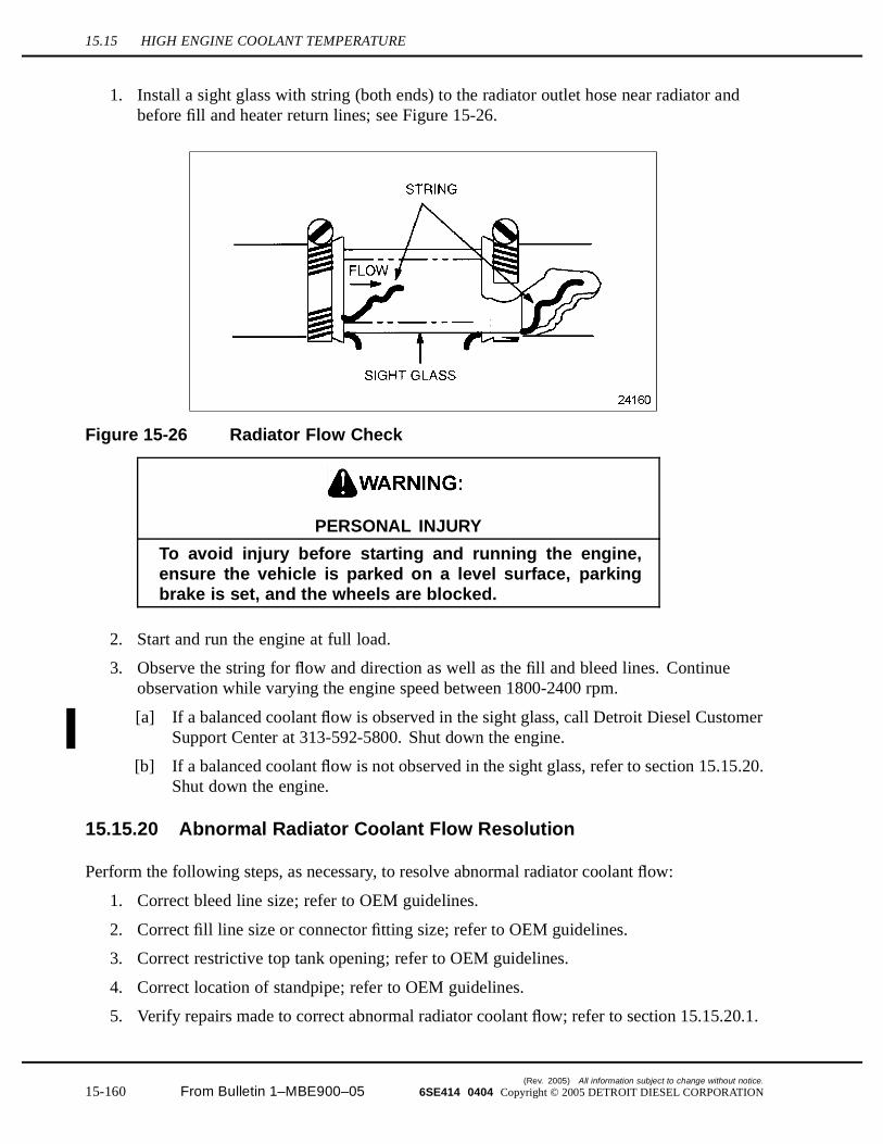
15.15 HIGH ENGINE COOLANT TEMPERATURE
1. Install a sight glass with string (both ends) to the radiator outlet hose near radiator andbefore fill and heater return lines; see Figure 15-26.
Figure 15-26 Radiator Flow Check
PERSONAL INJURY
To avoid injury before starting and running the engine,ensure the vehicle is parked on a level surface, parkingbrake is set, and the wheels are blocked.
2. Start and run the engine at full load.
3. Observe the string for flow and direction as well as the fill and bleed lines. Continueobservation while varying the engine speed between 1800-2400 rpm.
[a] If a balanced coolant flow is observed in the sight glass, call Detroit Diesel CustomerSupport Center at 313-592-5800. Shut down the engine.
[b] If a balanced coolant flow is not observed in the sight glass, refer to section 15.15.20.Shut down the engine.
15.15.20 Abnormal Radiator Coolant Flow Resolution
Perform the following steps, as necessary, to resolve abnormal radiator coolant flow:
1. Correct bleed line size; refer to OEM guidelines.
2. Correct fill line size or connector fitting size; refer to OEM guidelines.
3. Correct restrictive top tank opening; refer to OEM guidelines.
4. Correct location of standpipe; refer to OEM guidelines.
5. Verify repairs made to correct abnormal radiator coolant flow; refer to section 15.15.20.1.
(Rev. 2005) All information subject to change without notice.
15-160 From Bulletin 1–MBE900–05 6SE414 0404 Copyright © 2005 DETROIT DIESEL CORPORATION
MBE900 SERVICE MANUAL
15.15.20.1 Test Engine with Resolved Radiator Coolant Flow
Perform the following to determine if abnormal radiator coolant flow repair resolved high enginecoolant temperature:
PERSONAL INJURY
To avoid injury before starting and running the engine,ensure the vehicle is parked on a level surface, parkingbrake is set, and the wheels are blocked.
1. Start and run the engine.
2. Run the engine through its operating range with no-load for approximately five minutes,allowing the engine coolant to reach normal operating range.
[a] If the engine coolant temperature is 82-105°C (180-221°F), no further troubleshootingis required. Shut down the engine.
[b] If the engine coolant temperature is not 82-105°C (180-221°F), shut down the engine.Call the Detroit Diesel Customer Support Center at 313-592-5800.
All information subject to change without notice. (Rev. 2005)
6SE414 0404 Copyright © 2005 DETROIT DIESEL CORPORATION From Bulletin 1–MBE900–05 15-161
15.16 LOW COOLANT TEMPERATURE
15.16 LOW COOLANT TEMPERATURE
There are several causes for low coolant temperature. These probable causes are:
Faulty Thermostats Insufficient Radiator Air Circulation
15.16.1 Troubleshooting Procedure for Faulty Thermostats
To determine if faulty thermostats are causing low engine coolant temperature, perform thefollowing steps:
1. Remove thermostat from the thermostat housing; refer to section 4.6.1.
2. Inspect thermostat for correct operation; refer to section 4.6.1.1.
[a] If the thermostat is fully open at 95°C (203°F), check insufficient radiator aircirculation; refer to section 15.16.3.
[b] If the thermostat is not fully open at 95°C (203°F), refer to section 15.16.2.
15.16.2 Thermostat Replacement
Perform the following steps to replace thermostats:
1. Install new thermostat; refer to section 4.6.2.
2. Verify replaced thermostat; refer to section 15.16.2.1.
15.16.2.1 Test Engine with New Thermostat
Perform the following steps to determine if thermostat replacement resolved low engine coolanttemperature:
PERSONAL INJURY
To avoid injury before starting and running the engine,ensure the vehicle is parked on a level surface, parkingbrake is set, and the wheels are blocked.
1. Start and run the engine.
2. Run the engine through its operating range with no-load for approximately five minutes,allowing the engine coolant to reach normal operating range.
[a] If the engine coolant temperature is 82-105°C (180-221°F), no further troubleshootingis required. Shut down the engine.
[b] If the engine coolant temperature is not 82-105°C (180-221°F), shut down the engine.Check insufficient radiator air circulation; refer to section 15.16.3.
(Rev. 2005) All information subject to change without notice.
15-162 From Bulletin 1–MBE900–05 6SE414 0404 Copyright © 2005 DETROIT DIESEL CORPORATION
MBE900 SERVICE MANUAL
15.16.3 Troubleshooting Procedure for Insufficient Radiator AirCirculation
To determine if insufficient radiator air circulation is causing low engine coolant temperature,visually examine the radiator and radiator shrouding.
1. If the radiator has excessive clogging, debris, or dirt, refer to section 15.16.4.
2. If the radiator shrouding is not damaged, incorrectly positioned, or inadequate, and if theradiator is absent of clogging, debris, and dirt, then call Detroit Diesel Customer SupportCenter at 313-592-5800.
3. If the radiator shrouding is damaged, incorrectly positioned, or inadequate, refer to section15.16.5.
15.16.4 Exterior Radiator Repair
Perform the following steps for exterior radiator repair:
1. Clean the exterior radiator of all clogging, debris, or excessive dirt; refer to OEMguidelines.
2. Verify exterior radiator repair; refer to section 15.16.5.1.
15.16.5 Radiator Shroud Repair
Perform the following steps for radiator shroud repair:
1. Repair or replace damaged radiator shrouding; refer to OEM guidelines.
2. Verify exterior radiator repair; refer to section 15.16.5.1.
15.16.5.1 Test Engine with Repaired Exterior Radiator and Shrouding
Perform the following steps to determine if exterior radiator or shrouding repair resolved the lowengine coolant temperature:
PERSONAL INJURY
To avoid injury before starting and running the engine,ensure the vehicle is parked on a level surface, parkingbrake is set, and the wheels are blocked.
1. Start and run the engine.
2. Run the engine through its operating range with no-load condition for approximately fiveminutes, allowing the engine coolant to reach normal operating range.
All information subject to change without notice. (Rev. 2005)
6SE414 0404 Copyright © 2005 DETROIT DIESEL CORPORATION From Bulletin 1–MBE900–05 15-163

15.16 LOW COOLANT TEMPERATURE
[a] If the engine coolant temperature is 82-105°C (180-221°F), no further troubleshootingis required. Shut down the engine.
[b] If the engine coolant temperature is not 82-105°C (180-221°F), shut down the engine.Call Detroit Diesel Customer Support Center at 313-592-5800.
(Rev. 2005) All information subject to change without notice.
15-164 From Bulletin 1–MBE900–05 6SE414 0404 Copyright © 2005 DETROIT DIESEL CORPORATION
MBE900 SERVICE MANUAL
15.17 POOR FUEL ECONOMY
Customer expectations of fuel economy are usually based on past experiences, recommendationsfrom colleagues or sales staff, and wishful thinking. It is paramount that the end user attainreasonable expectations, based on sound predictions. Fuel economy management can beaccomplished with the aid of Detroit Diesel's Spec Manager® computer program. The programtakes into consideration a number of factors such as vehicle design, duty cycle, and route profileas it predicts real world fuel economy. Contact the local Detroit Diesel distributor for SpecManager support, prior to contacting the factory. Make sure that there is sound basis for the poorfuel economy complaint. These precautions applies to both new and in-service vehicles.
There are many variables which may affect fuel economy. Included are:
Vehicle Frontal Area Vehicle Weight Rolling Resistance (Static and rolling) Air Resistance (Excessive add-ons increase air resistance; trailer gap too large) Engine Speed Tire Size (Revs/mile) Axle Ratio Transmission Gear Ratios Road Surface (Cement, blacktop, gravel) Duty Schedule (Highway, stop-and-go, excessive idling) Vehicle Maintenance (Plugged air filter, low tire pressure, poor wheel alignment, brakes
dragging) Vehicle Cruise Speed Driver Habits Weather Conditions
NOTE:If any of these variables is not optimized, a serious penalty in fuel economy will result.Many of these items are out of the operator's control. However, there are factors that canbe controlled and have a major impact on fuel economy.
15.17.1 Troubleshooting Guidelines for Vehicle Cruise Speed
One of the most common factors that reduces fuel economy is vehicle cruise speed.
All information subject to change without notice. (Rev. 2005)
6SE414 0404 Copyright © 2005 DETROIT DIESEL CORPORATION From Bulletin 1–MBE900–05 15-165
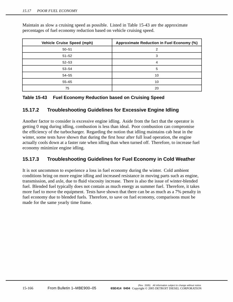
15.17 POOR FUEL ECONOMY
Maintain as slow a cruising speed as possible. Listed in Table 15-43 are the approximatepercentages of fuel economy reduction based on vehicle cruising speed.
Vehicle Cruise Speed (mph) Approximate Reduction in Fuel Economy (%)
50–51 2
51–52 3
52–53 4
53–54 5
54–55 10
55–65 10
75 20
Table 15-43 Fuel Economy Reduction based on Cruising Speed
15.17.2 Troubleshooting Guidelines for Excessive Engine Idling
Another factor to consider is excessive engine idling. Aside from the fact that the operator isgetting 0 mpg during idling, combustion is less than ideal. Poor combustion can compromisethe efficiency of the turbocharger. Regarding the notion that idling maintains cab heat in thewinter, some tests have shown that during the first hour after full load operation, the engineactually cools down at a faster rate when idling than when turned off. Therefore, to increase fueleconomy minimize engine idling.
15.17.3 Troubleshooting Guidelines for Fuel Economy in Cold Weather
It is not uncommon to experience a loss in fuel economy during the winter. Cold ambientconditions bring on more engine idling and increased resistance in moving parts such as engine,transmission, and axle, due to fluid viscosity increase. There is also the issue of winter-blendedfuel. Blended fuel typically does not contain as much energy as summer fuel. Therefore, it takesmore fuel to move the equipment. Tests have shown that there can be as much as a 7% penalty infuel economy due to blended fuels. Therefore, to save on fuel economy, comparisons must bemade for the same yearly time frame.
(Rev. 2005) All information subject to change without notice.
15-166 From Bulletin 1–MBE900–05 6SE414 0404 Copyright © 2005 DETROIT DIESEL CORPORATION