1 master of science approvedx approved s march · 1 aerodynamic strip theory ... might arise as a...
TRANSCRIPT

1FLUTTER OF HECTANGULAR SIMPLY SUPPORTED
PANELS AT HIGH SUPERSONIC SPEEDSby
John Mills Hedgepeth
Thesis submitted to the Graduate Faculty of the
Virginia Polytechnic Institute, in candidacy for the degree of
1 MASTER OF SCIENCE1 in
Applied Mechanics
APPROVED x APPROVED s
{_P I. g, -5 [
Director of Graduate Studies Head of Department
gg,(Y
(1 fg 1°,€'<-„i;‘; , , gi-·„,·Deanof Engineering Major Professor1 , March1957N
Blaoksburg, Virginia
N1 .
1

1 2 1TABLE OF CONTENTS
1
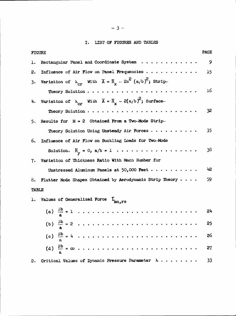
PAGEI. LIST OF FIGURES AND TABLES.......... . . . . . 3
II. INTRODUCTION..... . . . .............. 1;
IILSYMBOLS......................... 6IV. OF PROBLEM.................. 8
1 V. mmxszs........................ ll 11 Aerodynamic Strip Theory............ . . . ll 1
Exact solution................... 13solution . . . . . . ............ 18
Aerodynamic Surface Theory.............. 20
AirFo1··ces..................... 20Modalso1ution................... 21 1Calculaticns for an example panel.......... 28 1
VI. DISCUSSION......... . . ............ 31;
Accuracy of Static Aerodynamic Approximation . . . . . 31; 1Buckling Behavior ................... 36
1
Panel Thickness . . . ...... . . ......... 1111
VII. CONCLUDING REMARKS................... hh 1V1::. Rarmmcm . . . 1....................1,5IX.VITA.......... . . ............. . 119
1
X. APPENDIX -· EVALUATION OF 50 1FUIPTEI MJDE SHAPES FOR AERODYNAMIC
sum? Tama:................ 561
1 1
.. 3 „.
I. LIST OF FIGURE AWD TABLES
FIGURE PAGE 7
l. Rectangular Panel and Coordinate System............ 9 N2. Influence of Air Flow on Panel Frequencies........... 15 N3. Variation of Ac? With Ä == RX - 2112 (a/b )2; Strip—~
3
Theory Solution....................... 16 NM. Variation of Acr With Ä = RX —- 2(a/b )2; Surface—— 7
Theory Solution...... . ........... . . . . . 32 N
5. Results for M =¤ 2 Obtained. From a Two—~Mod.e Strip~-N
Theory Solution Using Unsteady Air Forces.......... 35N
6. Influence of Air Flow on Buckling Loans for Two—Mod.e N
Solution. Ry == 0, a/b =¤ l................. 383
7. Variation of iüzickness Ratio With Mach Number for NUnstressed. Aluminum Panels at 50,000 Feet..........M28.
Flutter Mode Shapes Obtained by Aerodynamic Strip Theory.... 59 F
TABLEl. Values of Generalized Force Emußs
(a)33l)-¤l......................... 2Ma(b) @3 s 2......................... 25
a(c)33P—=M......................... 26
a(:1) @3 = so......................... 27
a2. Critical Values of Dynamic Pressure Parameter A........ . 33

M
- M -M
II. INTRODUCTION
The aeroelastic instability of aircraft skin panols has been
the subject of a number of theoretical investigations.l°2l Mbst of
these papersl”l6 have dealt in some detail with the problem of a one-
dimensional panl in a two-dimsnsional flow and have been attempts
either to establish approximate stability bounaries for use in the
design of flat or slightly curved panels or to investigate some of
the apparent peculiarities of the panel—flutter phenomsnon. The aero-
elastic behavior of thin cylinders has also been considered,l7*l8
although in a somewhat preliminary fashion. In addition, the flutter
of two-dimensional flat panels in a three-dimansional flow has been
treated by Eisleylg and Luke, St. John, and Gross2O'2l. It is to the
latter subject that this thesis is directed.
The work both of Eisley and of Luke, St. John, and Gross con-
cerns the flutter of rectangular simply supported plates subjected to
supersonic flow over one side; both analyses euploy model solutions
and present numerical results for a variety of panel aspect ratios for
a limited range of supersonic Mach numers. No attention is paid,
however, either to the higher Mach numbers (yeater than 2) or to the
effects of midplane tension and oompression stresses on flutter. In
addition, neither analysis is completely satisfactory fbr an isolated
panel; Eisley used linearized two-dinsional unsteady-flow theory
and Luke, et al, while employing three-dimnsional theory, actually
solve the problem of an infinite-span panel separated into rectangular
bays by equally spaced, rigid streamwise stiffeners.

- 5 -
‘
In this thesis we consider again the flat rectangular simply
supported plate. The important departure from the previous analyses
is in the use of so-called "static" air forces,2 for solving the
flutter problem. Experience has shown that this static approximation
yields flutter boundaries that exhibit excellent agreement with those
yielded by more refined (with regard to unsteady effects) aerodynamic
theories provided that the Nach number is sufficiently high.* The
use of the static air forces as the obvious virtue of simplicity and
allows the inclusion of three-dimensional aerodynamic forces in a
relatively simple manner. In addition, large ranges of the pertinent
parameters of the problem can be readily investigated. Also, studies
of the effects on the flutter boundaries of the midplane stresses which
might arise as a result of loading and aerodynamic heating are feasible.
Because of the paucity of experimental information pertaining to
the flutter of flat, unbuckled panels, it is not possible to assess
the overall accuracy of any panel flutter theory. Consequently, state-
ments regarding the validity of the theory contained herein are based
on comparisons with re refined (and, presumably, more accurate)
theories.
The help of Prof. Daniel Frederick in preparing this thesis is
hereby acknowledged. Appreciation is also due to Miss Lillie Belle
Evans and Mr. Keith Redner of the staff of the National Advisory
Committee for Aeronautics for their valuable aid in performing the
numerical computations.
*Comparisons presented in a subsequent section show that thelower limit on Mach number is somewhere between VÜ? and 2.

N
.. 6 ..
III. SYMBOLS I
A RX • 2n2¤2(a/b)2
K Äx ·· 2112 (a/b)2 (Note that flutter is usual.ly
mostcriticalfor n · 1)I
BB2ÄE2 + n2(a/b)2I-Yy
-—..2..Bo (B/b> ay -(a/¤>L‘
C(m,o) integral defined by equation (Alb)
D platestiffness,E
Young‘s modulus of elaeticity
Imn’Jm’ functions used in evaluation of generalized fbrceK L (see Appendix)mn’ mn
Immrs generalized force of (rs) mode on (mn) modeM Mach number
Nx,Ny midplane stresses (positive in compression)
RX Nxaz/D2Ry Nya /D
S(m,c) integral defined by equation (A10)
U velocity of air flcw
Wh complex amplitude of panel vibration (see eq. (h))
a,b dimensions of panel (see fig. l)

.. 7 .. 7
cm amplitude of (mn) mode (see eq. (19))7h panel thickness 7
k frequency parameter, m2
k/u2
Z lateral aerodynamic loading
im lateral aerodynamic loading due to (mn) mda
j,m,n,r,s integers
q dynamic pressure, pU2/2
t timew lateral deflection of panel
x,y,z Cartesian coordinates (see fig. 1)
xl x/a
5 (lt? - 17 mass density of plate
6 mass ratio, P8/rh
q; perturbation velocity potentialX dynamic presaure parameter, 2qa3/ßD
ACI, critical value of 1L1. transtability value of X
p. Poissorüs ratio
p mass density of air
¤ ä ääoo circular frequency
1(y) step function, equal to zero for y< 0 and eqrnl tounity for y> O
7

.. 3 .. X
IV. STATEMENT OF PROBLEM VThe configuration to be analyzed herein is shown in Figure l.
(
It consists of a simply supported flat plate of uniform thickness h
mounted in a rigid wall with air flowing over the top at a meh
number M. The plate has a length a and a width b and is sub-
jected to constant midplane force intensities NX and Ny (positive
in compression).In the following analysis, smalbdeflecticn thin-plate theory
is assumed to apply. The appropriate equilibrium equation and
boundary conditions are:
Dvb! + Nxwm + Nywyy + Thwtt - l(x,y,t) (1)
w(x,O,t) • w(x,b,t) ¤ w(O,y,t) == w(a,y,t) == O
wyy(x,O,t) =· ww(x,b,t) ·- wm(0,y,·«.) · wxX(a,y,t) - 0
where w(x,y,t) is the lateral deflection of the plate and 1.(x,y,t)
is the lateral load per unit area due to aerodynamic pressures;
D is the plate stiffness Eh3/l2(l -· $:.2) and 7 is the density of
the plate material.
As was mentioned in the Introdmtion we will assume that the air
forces yielded by linearized static aerodynamic theory give an
adequate approximation for this problem. In this theory, the loading
at each instant is taken to be the loading which would result from
flow over a stationary surface with a shape the same as the shape of

N IN
— 9 - II
ZAIE /1y
N M //4 Q ---- 7
bFig.l.- Rectangular panel and coordinate system.

— 10
-thedeflected plate at that instant. Thus no time-dependent effects
are considered in either the potential equation, the boundary con-
ditions, or the pressure—potential relations. Note tht this differs
(on the side of simplicity) from the so-called "quasi-steady" theory,
in which time derivatives are included in the boundary conditions and
pressure·potential relations and from the first-order theoryzz in
which time—dependent effects are included approximately in all three
governing relations.
As is usual in the treatment of flutter problems, the analysis
contained herein is of the dynamic stability type. That is, condi-
tions are sought for which an unstable (growing with time), self-
excited motion is possible. The existence of such a possible motion
would then imply instability of the panel since an small disturbance
would "trigger" the motion.
In the following sections a closed-form solution of equation (1)
is first carried out for two·dimensiona1 aerodynamic theory (strip
theory). The same problem is then solved by the Galerkin procedure
in order to investigate the convergence of this modal approach.
Finally, a modal solution of equation (1) for three-dimensional theory
(surface theory) is presented.

- ll - (V.ANALYSISAerodynamicStrip Theory
For strip theory, the lateral leading is given by the simpleAckeret value
2Y·(><.y„’¤)· · ggg- wX(><„;v„t) (2)
where q is the dynamic pressure pU2/2 and 3 - (xu - 1.Equation (l) then becomes
Dvbw + Nxwm + blyxvyy + gg- wx + yhwrtt ··· 0 (3)
For the simply supported plate a solution of equation (2) can
be written in the form:
vr • Re|§'IH(x)sin E? ([1)
The frequency m is, in general, complex; however, we direct ourattention primarily to real values of 6:, for which the motion inharmonic.
Substituting equation (L1) into equation (3) and the associatedboundary conditions and nondiznensionalizing yields:
IV 2 2 a 2 M M a 2 2 2 e 2 2hh -· 211 TL Tf (*6) Wu + }„Wn' ·k Wü •· 0
(5)

4.. 12 ..
(91 II 7wn(0) · wu (0) - w¤(1) · wu (1) - 0
where the primes denote differentiation with respect to xl - x/a and
NxazRx ° D
·Nyaz
Fx 11 (6)X
•ßD
Thühkz " -*-13-- 022
Equation (5) and the boundary conditions constitute an eigenvalueproblem where k2 can be considered to be the eigenvalue. We seek,
in fact, the values of 71, RX, and R}, for which one of the eigen-
values k2 becomes complex and, hence, the panel becomes unstable.
(See ¤q~ (h)-)Equation (5) can be rewrittem
wnm + Awn" + 1w„' — swg, -· 0 (7)where
2 2 a 2A • RX - 211 TI (E)(8)
2 74B - k2 + 112112 ·• 1'1hT(h<·ä->
Note that B now takes on the role of the eigenvalue.

7.. ..
lExact solution.- The chaxacteristic equation for equation (7) is
p)4+Ap2+).p·-B==O
The roots of this equation can be written in the form]'3
p ¤- -¤ I 6, a * 16
where
,V
>. 2 56 EI. + 41 +2
E 2 (9)
2 2B .. ..;..5 - „<„2 . g)16a
Substituting the form
wn niepixl1-l
in the boundary conditions yields the following condition for anontrivial solution
2[(62 + 62) + L;a2(ö2 — czgsin 6 sinh 6 ·· 8a266(cosh 6 cos 6 ·— cosh 2a)
<1¤>The eigenvalm B can be computed for fixed values of ). and A
by varying a until equation (10) is satisfied and then using the last
l _, cr.

W- lb -
of equations (9) to determine B. The resulting solutions can be
shown in the form of plots of X versus B for various values of A.
An example plot for A • O is indicated by the solid line in Figure 2.
(The abscissa is instead of B in order to allow the inclusionof large ranges of B conveniently.)
It can be seen tht for a fixed value of X there exists an
infinite discrete set of values of B. For X - O, the values of B
can be shown to correspond to the natural frequencies of the plate
in a vacuum. Increasing the dynamic-pressure parameter X merely
changes the values of B (and, hence, the natural frequencies)
smoothly until a critical value (denoted Xcr in Fig. 2) is reached.
At this value, two of the roots for B become equal. For X.< Xcr,the values of the frequencies remain real (provided the panel is
unbuckled for X = O) and, thus, the panel is stable. For X.> Xcr,
two of the values of B become complex; hence, in view of equations (h),
(6), and (8), the panel has at least one unstable mode of oscillation.
Therefore, the value Xcr defines the flutter boundary. (Note thatother roots for B ‘would coalesce and become complex if X ·were
increased further, thereby producing additional unstable modes. These
secondary critical values are symbolized by the dotted lines in
mg. 2.)
The variation of Xcr ‘with A has been calculated and is shownby the solid line in Figure jf.
The abscissa here is
E · fi = Ex - 2n2<%>2 (11)*Some examples of the shape of the flutter made are presented
in the Appendix for interest.W

I - 15 -
8OO600ß
1 .4OO XC',
lO I 2 3 4 5 6l/
Fig. 2.- lnfluence of air flow on panel frequenciee.

-— 16 —
I2OOTHREE TERMS7
IOOO000
EXACE7FOUIST ‘rc,6004oo —„
TWO TERMSJA T\‘-ig
2OOO
-5 -4 -3 -2 —| 9 I 2 3 4 5A „
Fig. 5.- Variation of XC? with Ä = F? — 2n2(a/h)2; 6trip—theorysolution.

- 17 - rwhere 7FX ·· ig-(12)n
Note that for ÄÄ< S, Ac? decreases monotonically with‘Ä;
thus, fbr
fixed values of ä& and a/b, the lowest value of lcr would beachieved fer n - 1. The resulting shape of the flutter mode in the
y-direction weuld be a half sine wave.
Although a full discussion of th flutter boundary in Figure 3 is
included in a later section of this thesis, a mntion of severalsalient points is warranted here. The first is that the flutter speed
is independent of By. This result, which comes about from the lackof coupling between the various modes in the y—direction, is of
interest in connection with wing panels fer which the greatest stress
is usually in the spanwise (y) direction. Secondly, the range of F
validity of the results in Figure 3 is limited by the buckling charac-
teristics of he plate. For instance, a square plate with no stress
am es y—«111~aee1¤¤ (R5, - 0) weuld bucme (rer >. -· 0) if Fx 2 hg forthis reason, the curve in Figure 3 would be valid only fer Ä < 2.*
Other values of a/b and Ry weuld yield other ranges of validity.
Thirdly, the critical dynamic-pressure parameter is finite when the _
panel is on the verge of buokling even though the ”effective stif£ness”
of the panel (as measured by the lowest in-vacuo natural frequency)
*Since the buckllng lod is affected by the air forces, thisinequality is not strictly correct. This phenomenon is discussed ina later section.

.. 18 ..
approaches zero. Finally, the critical dynamic-pressure parametergoes to zero at 'Ä equal to 5. The need of large panel thicknessesif
—Ä~5 is obvious.
Galerkin solution.- In order to investigate the convergence of
the modal procedure, a Galerkin solution of equation (7) will beperformed.
Let
JWH •
E cm ein mnxlm·l
Substituting into equaticn (7}: multiplying by sin rnxl, and inte-
grating yields the following set of equations for the coeffioients cm
"3 r=•l ’
where
2 2 L;.. B . k 2 s - h a“NbNn n
·— Q rmL¤m1·¤'¤°§”"'§‘“'“·""“"°°dd‘° r ·- m
(ll;)-1:m,N ··· 0; n ¤ s, m + r even
Lm,rs • O; n f s
N

r
.. 19 -
In the first of the latter expressions, B3, • Ry/112. The seeminglyovercomplicated form for the generalized aerodynamic·force coeffi—
oient elgmßs is introduced at this point to agree with the notationin the next section.
For a nontrivial solution, the determinant of the coefficientsof cm must equal zero. If J - 2, for instance,
1 — K - E - lg 13n
¤ Og .. ..A 16 — LA · BSU?
Upon expanding and solving for K we get
nh ·· ·- ·- ·->.-ZE-(A+B-1)(16-LA-B) (1;)
This relation is illustrated by the dashed line in Figue 2 for Ä • O.The tw¤·-·term approximation to the critical value of X can be obtainedby finding the maximum; the resultiskm,
•16 5 -· A (16)
This approximation and the three-term and four—term approxi—·
mations (,1 • 3 and L) are compared in Figure 3 with the exact result.It can be seen that the two··term approximation consistently under-
estimates lcr, the error increasing as Ä becomes large negatively.

.. gg ..r
The three-term approximation is satisfactory for small values of Ä
but is again unsatisfactory for the larger negative values of Ä.
On the other hand, the four-term solution yields good results over the
entire range of A considered}
Aerodynamio Surface Theory
The results in the preceding section were obtained on the basis
of aerodynamic strip theory. The influence of three-dimensional
aerodynamic effects on the flutter bommdery is cf interest. In this
section, the flutter of the rectangular panel in a three-dimensicnal
flow is analyzed by means of the Galerkin solution.
Air Forces.- The lateral loading due to the supersonic flow above
the panel can be found in a straightforwsrd manner by means cf source-
euperposition techniques. Thus, if the deflection of the panel is
w(x,y,t), the lateral load 1„(x,y,t) iszh
l(x,y,t) ·· pü ggf (>¤,y,’¤) (17)where
U « dl')q>(x,y,t) "
"‘EU8
"""""”"""""""""""""""""""“ (18)Jh: ·— U2 ·· ß2(y — n)2
The integration is carried out over the forward Mach cone from thep¤i¤‘¤ (XJ)- 1
*It should be menticned that the four-terg solution would also beinaccurate for very large negative values of A. In this case, thebehavior of the plate approaches that of a meubrane for mich theGalerkin solution is known to be inapplicable.23

.. 21 -
In the mdal solution the deflection is expreesed as the series
vr sin F-EF sin (19)
in the region O 5 x 5 a, 0 5 y 5 b. The corresponding loading is
1(x,y,t) =· cI.SlI.S(x,y)ei°°t’ ;| (20)r s
where
T Ö x cos einlr 2 2(X-!) ·B(Y*‘V1)
[101) —· ]_(n -· büdn dä (21)
Note that the step—function expression
10*2) ·1(n·b) -=¤s ¤<¤• 1; O < 1} < b
• 0; 1} > b
excludes the regions outside of the plate from the integration.
Modal solution.- Substituting equations (19) and (20) into the
equilibrium equatiorx, equation (1), gives

I
I- 22-_
2D fi , 2€2?. _ D äänä __a2 b2 In #121· s -
621-:2 D 3 i rm; ina 1*1--;-6 b —crsZrs(x,y) - 0
If bmg ¤qu2.·¤1b¤ 16 mu1·b1p11¤d by am nn? am P2} ma mugabsd,the result is
2 2 —- 2- •-2 ..{Enz "' n2<§)iI " manu: " n2<%) By " In Ii °m¤ " fn; ii; L!lKl,I‘8cI°5(22)
whereY:.
-k/112 and
·· . 222 jdn fn 222 222L¤m,z•s nab O O am a an b X
6‘x y+·:I'-(X-§) eossinEx-0
-1III —§) ,I 2 2 2 Xypfx (X-?·)-B(y-n)
[lm) -· im —bildm ds} dx dy

I
.. 23 ..
is the generalized force of the (rs) mode on the (mn) mode. Inte-
yation by parts yields
imJS azb O O O y—1(x·-Q,)E (le — og — so — ez
@01) ·— 101 —· büdn di dx dv (23)
Before continuing, it is necessary to determine these generalized
forces. As is usual for supersonic-aerodynamic problems, the
generalized forces can be shown to be functions of the modified aspect
ratio parameter ßb/a. For ßb/a ,2 1, the reduction of the expression
for -f.¤m’x,S in terms cf Bessel and Struve functions axd two readilyevaluated single numerical integrations is possible; this reduction is
carried out in the Appendix. Values of °fm,rs for ßb/a • l, 2, 11
and m, n, r, s -= 1, 2, 3, L1 are given in Table 1. Also given are
the values for the two-dimensional case (ßb/a ··¤•) obtained from
equation (15).
It should be noted that lmmra =· O when n + s is odd. Thus,flutter modus are either symmetric (n - 1, 3, . . .) or antisymmetric
(n - 2, 11, . . .) about the midspan. Also, the generalized force
possesses the following symustry properties
imn,rs ° i-ms,rn
T*1¤n,rs " E-rn,ms$ m + 1° °"°“
i1m,rs ° °‘frn,ms·‘ m + r Odd

I
° ° I
I
TABLE 1. - VALUES OF GENERALIZED FORCE
i!I]I1,I‘S
(+) gg = l
11 21 51 1+1 15 25 55 1+511 0.280799 0.918988 -0.01079+ 0.5+255+ -0.09+02+ 0.027056 0.0715+8 0.051672
21 -.918988 . 1; 1.707919 .062655 -.027056 -.22501+0 -.179612 -.052125
51 - .016791+ -1. 707919 . 070016 2 . 278778 .07151+8 . 179612 - .005225 — . 122558
+1 -.5+255+ .002055 -2.278778 .0++78+ -.051672 -.052125 .122558 .11590+
15 -.091+021+ .027056 .07151+8 .051672 .591+560 .179055 —. 517892 .271509
25 -.027056 -.22501+0 -.179612 -.052125 -.179055 1.585+01 1. il 59*517 -.1+99257
55 .0715+8 .179012 -.005225 -.122558 -.517892 -1.559517 2.250015 5.1975+9
1+5 -.051672 -.052125 .122558 .115961+ -.271509 - .1+99257 -5.19751+9 1.2811+62
12 22 52 1+2 11+ 21+ 51+ 1+1+12 0.517757 0.0+5152 -0.252+72 0.2+80++ 0.009291 0.158695 0.078055 -0.00810+
22 -.61+5152 1.117025 1.969181+ .02551+5 -.158695 -.266500 .055955 .178951+
52 -.252+72 -1.90918+ .70+8+0 2.752580 .078055 -.055955 -.+82967 -.+11002
+2 -.2+80++ .0255+5 -2.752580 .2165M7 .00810+ .178958 .+11002 .050558
1+ .009251 .158095 .078055 -.00810+ .28258+ .050501 -.0859+8 .209+00
21+ -.158695 -.286560 .055955 .178951+ -.056501 1.227635 .576756 -.617150
5+ .078055 -.055955 -.+82907 -.+11002 -.0¤5)+8 -.576756 2.984986 2.125151
++ .00810+ .17895+ .+11002 .050558 -.269960 -.617150 -2.125151 5.055+2+

I
I · 25 ·I
'TI·.1;LM 1.- VALUES OF 0ENEmL12.E0 12012012 - COHCÄHUGÖ(2) E.? = 2
ll El jl 2l 15 25 55 25
ll 0.115757 0. 910125 0.022577 0 . 559008 -0.056992 -0.025205 -0. 018266 -0.012028
21 - . 910125 . 056088 1 .566619 . 012605 . 025205 .005858 - . 019678 - . 015282
51 .022577 -1.566619 .011287 2.205615 -.018266 .019978 .025528 .006027
21 - . 559008 .012605 -2 . 205615 .008108 .012028 - . 015282 - .006027 .005112
15 -.056992 -.025205 -.018266 -.012028 .550582 .889221 -.127650 .287169
25 .025205 .005858 - .019678 - .015282 - .88 9221 . 722612 2 . 009015 . 171298
55 -.018266 .019678 .025528 .006027 -.127650 -2.009015 .168158 2.22955925 .012028 -.015282 -.006027 .005112 -.287169 .171298 -2.229559 .087275
12 22 52 22 12 22 52 2212 0. 562129 0. 985525 0 .015851 0. 562869 -0 . 080855 -0. 051587 0.012926 0.010780
22 -.985525 .221190 1.729682 .078551 .051587 -.069568 -.098219 -.058556
52 .015851 -1.729682 .059022 2.269501 .012926 .098219 .068260 .010209
22 -.562869 .078551 -2.269501 .022120 -.010780 -.058556 -.010209 .015761
12 -.080855 -.051587 .012926 .010780 .569556 .595959 -.525652 .19167722 .051587 -.069568 -.098219 -.058556 -.595959 1.559618 2.168729 .112766
52 .012926 .098219 .068260 .010209 - . 525652 -2.168729 .657%0 2.805101
22 - .010780 -.058556 - .010209 .015761 - .191677 .112766 -2 .805101 .1. 552676

I
.. ggg -I
TABLE 1.- VALUES OF GENERALTZED E0BcE - COHÜÄDUQÖ
<¤> P; - I
ll 21 51 Hl 15 25 55 45ll 0.05u825 0.870251 0.009766 0.5u7509 -0.010958 -0.01056u -0.006599 -0.00u67821 -.870251 .00u086 1.555199 .OOlü78 .01056u .006575 .001822 .00155151 .009766 -1.555199 .005659 2.1895Äl -.006599 -.001822 .000568 -.000820Al -.5u7509 .OOl#Y8 -2.1895Äl .000995 .00u678 .001551 .000820 .OOlÄl615 -.010958 -.01056u -.006599 —.OOMÖT8 .26MYll .985087 .OÄ5§Ol .57956025 .01056u .006575 .001822 .001551 -.985087 .095516 1.628195 .05668755 -.006599 -.001822 .000568 -.000820 .0u5501 -1.628195 .017556 2.251651»A5 .00u678 .001551 .000820 .OOlÄl6 -.579560 .056687 -2.251651 .019055
12 22 52 M2 lü 2u 5I+ Im12 0.150759 O.92MM8Y 0.051581 0.565621 -0.025207 -0.022527 —0.0l2MYO -0.00885222 —.92MM8Y .0266ÄQ 1.565657 .010u55 .022527 .OlO9YM -.000285 -.OOO2MY52 .051581 -1.565657 .011565 2.206962 -.Ol2M7O .000285 .00uu95 .000228Ä2 -.565621 .010u55 -2.206962 .006059 .008852 -.OOO2HY -.000228 .002066lä -.025207 -.022527 -.Ol2Ä7O -.008852 .#O579Ä 1.018790 .029lÄÄ .575056QM .022527 .01097u -.000285 —.OOO2MT -1.018790 .252958 1.7u0565 .0861995u -.Ol2MTO .000285 .00uu95 .000228 .029lMM -1.7u0565 .280215 2.26M862uu .008852 -.OOO2MY -.000228 .002066 -.575056 .086199 —2.26&862 .090980

- Q7 ..
1.- VALUES OF 0E1~1ERAL1ZED FORCE - 0000104188ßb _(Ö) Q — °°
ll 21 5l Äl 15 25 55 M 5ll 0 0 .8M8820 0 0. 559551 0 0 0 021 -. . 1 0 1.527887 0 0 0 0 051 0 -1.527887 0 2.182090 0 0 0 0Ml - . 559551 0 -2.182090 0 0 0 0 0l5 0 0 0 0 0 -ö$«ö<%2<.> 0 . 5 555 jl25 0 0 0 0 -. 8M8820 0 1.527887 055 0 0 0 0 -1.527887 0 2.1824,00M5 0 0 0 0 - .559551 0 -2.182090 0
12 22 58 M2 lä 2M 5M MM12 0 0 .8M8820 0 0. 559551 0 0 0 022 -. 8M8820 0 1 . 527887 0 0 0 0 052 0 -1 . 527887 0 LZ . 182090 0 0 0 0M2 - . 559551 0 -2 .182090 0 0 0 0 0lM 0 0 0 0 0 . 8M882€— 0 . 5 55 51
QM 0 0 0 0 -.8M8820 0 1.527887 4,
5M 0 0 0 0 0 -1 . 527857 0 .lr4};_}c,MM0 0 O 0 - .559551 0 -;3.18-;+;9·„ 0

- 28 - 1
For Bb/a < 1, a similar, but more complicated, reduction can be
made. No results have been obtained for this case, however, primarilybecause they would be useful only for very low-aspect··ratio panels.
For example, values of Bb/a < 1 would correspond to Mach numbers lessthen J2- for a panel of unit aspect ratio. But, as will be demon-
strated, the static aerodynemic theory cannot be expected to yield
good results for this region.e
Calculations for an egggle panel.- In view of the resultsobtained for the modal solution for strip theory, it is evident that
the use of four modes in the x··direction should give satisfactory
accuracy. In the y-direction, it is convenient to include two modes:
. n · 1, since this oonstituted the most critical value for the strip-
theory solution; and n - 3, in order to include effects of spanwise
coupling.
Equation (22) then becomes
2 a 2 2 __ 2** _m + n m RX
m-izsn)2 » » »n2® Pw 1% °“‘“ :3 1--1,2,3,1, s•1,3 I‘““·*°°°‘°" O a · 1, 3
For a nontrivial solution, the detcrminant of the coefficients ofcm must be zero. When expanded, this determinant yields an eighth-
order equation in 1-E2 in which the ooefficients are dependent on A,EC,
läy,and a/b. As before we seek the lowest valm of X for fixed

.. ....
and a/b for which two of the sight roots for E2 become
complex. (For ). ¤ O, all roots are obviously real.) The calculations
have been carried out for a/b ¤ 1 and for a number of values of EXand 'Ihe following values for Aer were obtained:
For 8b/a -= 1
-1, 61,7.7 1,80.0 322.8 179.6 51,.38 1,6.63-2 61,7.7 1,80.0 322.8 179.6 51,.380 61,7.7 1,80.0 322.8 179.62 61,7.8 1,80.1 322.91, 61,8.0 1,80.3
For {Sb/a. =· 2
E *11 ·2 laY
6 -1, 81,7.7 668.2 1,95.8 333.9 186.3 56.56 1,6.35-2 668.2 1195.8 333.9 186.3 56.560 668.2 1195.8 333.9 186.32 668.2 1195.8 333.91, 668.2 1,95.6

... 3Q ..
For ßb/a = 11
ll859.8 676.9 502.5 338.6 189.1 57.55 ll9•39
676.9 502.5 338.6 189.1 57.55676.9 502.5 338.6 189•l
676.9 502.5 338.6
676.9 502.5
In the calculations for ßb/a == 1, 2, and lg, an automatic high-
speed digital computer was used. For each set of valuesforand
äy the determinant was expsnded for various selected values
of 1. The resulting eighth—order equation in E2 was then solved.
The critical value of 1. was found by an interpolation procedure.
A significant outcome cf these calculations is the virtual inde-—
pendence of her on the value of Evidently the ceupling
between the various modes in the y·—d:Lrection is slight, even for
Bb/a • 1. Since the coupling is so slight, it is improbsble that the
addition of more modes in the y·~direction wouJ.d change the results
appreciably. Thus the tabulated values can be considered to be
essentially correct.
The lack of dependence on äy also suggests the pcssibility
that the value of km? is dependent only on the parameter
1: - ai „ 21.312
11

4
- 31 -
as it was for the strip—theory solution. If this were the case, the
results for a/b • 1 could be extended to apply to other aspect
ratios through the use of this paramter. As a check, the vales
er nm, were calculated for a/b · 2, Fx · 1,, F}, · o anda/b - 1/2, Ex - -3.5, Nm - O. For ßb/a = 1, the resulting values
of Aer are 6h7.7 and 626.6, respeotively, in reasonable agreement
with the tabulated value fbr a/b • l, äg - -2, äy = O. Thus, the
extension can apparently be made. The variation of Xcm with Ä
is shown in Figure h for ßb/a · 1, 2, h, and.«• (strip theory);
the values are also given in Table 2. Note that for Ä · 5, the
critical dynamic-pressure parameter is zero fbr all values of Bb/a.
The significant results of this thesis are embodied in Table 2.
From this table, the critical values of X for isolated rectangular
simply supported panels can be found in terms of Ä fer a large
range of panel aspect ratio, midplane stress, and Mach number. The
necessary panel thicknees to prevent panel flutter can then be
calculated from the value cf lem. In this regard, it is interesting
to note that the aerodynamic erreet of finite aspect ratio on the
panel thickness is very small. Fer the range considered the variation
of Aer between ßb/a ·•¤ and ßb/a · 1 is approximately 6 percent;
the correspcnding variation cf thickness weuld be less than 2 percent.
44
4

I000
8OO $*1%*47
600t IrAcr /400
200
0-5 -4 -3 -2 -I 0 I 2 3 4 5Ä
Fig. II.- Variation of ACI. with Ä = ÜX — 2(a/h)2; surface-theorysolution.
III

l..
l l
lTABLE 2.- CRITICAL VALES OF DYNAMIC PRESSURE PARAMETER A
-6 822 BAB 860 865-A 6AB 668 677 680-2 A80 A96 502 5050 525 55A 559 5A12 179.6 186.5 189.1 190.5A 5A.A 56.6 57.6 58.0

...3h..1
VI. DISCUSSION1
Accuraoy of Static Aerodnamic Approximation
The results obtained by Eis1eyl9 by using linearized two-
dimensional usteadyeflow theory provide an excellent basis for
evaluating the accuracy of the static aerodynamic approximation
employed in this thesis. The results calculated by a two-mode Galerkin
solution for unstressed plates cf aspect ratio h, 2, 1, and l/2 sub-
jeoted to M · 2 flow are shown in Figure 5. The abscissa in this
figure is the well-known mass ratio
which does not appear in the preset analysis because of the simplicity
of the aerodynamic theory. Indeed, the values of ACT obtained fromthe static approximation are the same as those in Figure 5 for e ¤ O.
It is therefore apparent that the static approximation is adequte
if e is small enough.
In order to define the practical range of s, it is convenient tc
make use of the following combined parameter
e Ü Ü
where c is the speed of sound in the air. Note that, for fixed Mach
number, this parameter is dependent only on the properties of the air
and the plate material. For a particular altitude-material combination,

I
- 35 -I
1000 M=2 6I1I/44
06001 g_ 1' 0'ÜII6OO :Äcr I
I400 1 I1I 2
I 42OO I
11111
O .2 .4 .6 .8 IOfi7h
Fig. 5.- Results for M = 2 obtained from 6 two-mode strip-theorysolution using unsteady air forces.

-36...
therefore, A would vary as 63. The variation for magnesium at sealevel is indicated oy the dashed line in Figure S. For this altitude—material combination the error of the static approximation can beseen to be negligible. For higher altitudes or denser materials thecorresponding cubic line would lie above the one shown and the errorwould be less. lt is reasonable to conclude, therefore, that thestatic approximation yields satisfactory accuracy for M = 2.
Investigations of the frequency expansions of the flotter forces(see ref. 6, for example) shcw·that the accuracy of the static
approximation would be even better for Mach numbers greater than 2.For M < 2, however, the accuracy decreases. At~JM • 2, forinstance, the unsteady flow theory yields tw flutter boundaries6’l9
whereas the static theory predicts only one. It is paobable, there-fore, that a lower limit, somewhere between \/2- and 2, exists on theMech number range for which the results cbtained in this thesis areapplicable.
Buckling Behavior
It is generally agreed that buckling has an adverse effect on theflutter speed of panels. Past theoretical work on this subject,however, has dealt with only the two—dimensional panel~flutter problem.This work was pioneered by Isaacsl, who introduced the concept of the
”transtability" speed, a speed caloulated from purely_gtatig considere-tion that constitutes an uper limit on the flotter speed of the
buckled panel. Hayee2 and Milesg then demonstrated that thetranstability speed is indeed equal to the flutter speed for smallperturbations about the static equilibrium position.

·· 37 ···‘
The similarity between the governing equations of two~ and three-
dimensional panel flutter for strip theory with static air forces (see
eq. (7) and ref. 12) indicates that the flutter speed of a buckled
finite·—aspect·-ratio panel might also be obtained through a
transtability·type approach. A mwliminary investigation, limited
by the use of small·def1ection plate theory to small buckle depths,
of the static buckling behavior of panels is outlined here. Since
some of the results obtained are of unoertain validity, being unsup-·
ported by a dynamic analysis, the investigation is limited to a two-·
mode solution for simplicity.
The effect of the air forces on the buckling load can be determined
by setting E equal to zero in equation (15). Slightly rewritten,
the equation becomes
·~ 1><l6 ·· LX - Fo) (2L;)3n
where, for n - l
gv *ä-Y<%)2
·(äh
The buckling loads can be calculated from this equation. An example
plot of the variation of äx with X for a/b - l, Ey • O is shown
in Figure 6. Similar plots would result for other values of a/b
andI

1.. 38 ..
I00
XT8060
X40
20
1 1
0 I 2 3 4 5 6 7 8Rx
Fig. 6.- lmfluenco of air flow om bucklimg loads for two—mode solution.By Z o, a/b Z 1.
1

1.. 39 -
lThe transtability analysis for the two—d:Lmensional problem is 1
based on a plot like that in Figure 6. It is argued that a buckled
panel subjected to air flow would exhibit the midplane load given by
the left-hand branch of the curve. If X is increased, the load
would increase until the maximum of the curve is reached. Furtherincrease of X would necessarily produce motion of the panel since
there would be no stable static equilibrium position of the buckled
panel. (Presumably, the panel would be unstable at the higher buckling
loads not considered in the two·—mode solution.) The maximum valueof X given by the curve is the transtability valm .
The same line of reasoning can be used for the three-·dimensionalproblem provided that the buckle depth is kept small. For this case,
the results are dependent on the boundary conditions on in-·plane
deflections and stresses at the edges. Consider, for instance, a
buckled panel with streamwise edges having a prescribed stress end
spanwise edges having a presoribed displacement. For such boundary
conditions the value cf Fo would be fixed and the valm of Ä wouldbe that given by equation (21;). The resulting transtability value
of X would be found from the condition
Q: -· 0BA
which gives
Ä "Qglilh (25)T 32 O

I.. hg ...
I
IOn the other hand, a pael with the edge boundary conditions reversed
would have a fixed value of Ä and the appropriate transtability
condition would be
ät- • OseoThe resulting value of ÄT is
>„T II (26)
which is the same as that obtainsd for the unbuckled panel (see
eq. (16)); this result can, of course, be quite different from that
given by equation (25).
In a practical situation, the edge boundary conditions would
probably be different from either of the foregoing cases and different
values of AT would result; each situation requires separate
treatment.
A question might arise as to the usefulness of the small—deflection
theory in obtaining results pertaining to finite—aspect-ratio buckled
panels. It is felt, however, that such results represent correctly
the limiting case of vanishingly small buckle depths and, furtherore,
that this limiting case establishes a lower bound on the critical
value of A for buckled panels. Th latter conjeoture is based on
the demonstrated independence of lcr on buokle depth for the two-
dimensional problem12’l6 and the more rapid increase of stiffhess with
buckle depth for a finite·aspect—ratio plate than for an 1nfinite—
aspect-ratio plate (beam)2S. A test of the validity of the ccnjecture,

hl - Nand others implied in this section, must await a full—fledged dynamicanalysis of the aeroelastic behavior of three-dimensional buckledpanels including large—deflection structural effects.
Panel ThicknessTwo examples of the variation of the critical thicknees ratio
with Mach number as cbtained'by the present theory are indicated bythe olid lines in Figue 7. The results apply to ustressed aluminumpanels at an altitude cf 50,000 feet with aspect ratics of one andinfinity. As could be expected, the effect of reducing the aspectratio is to reduce the required h/a.
Also shown in Figure 7 are the results calculated from unsteady—flow theory for the lower supersonic Mach numbers by Luke andSt. Johnzl. These results, which are indicated by the dashed lines,mrge well with the predictions of the present analysis. Th metingis nearly exact for the aspect ratio cf infinity if account is takenof the fact that the dashed lines wee obtained from a two—mcdesolutionzl whereas the solid lines were obtained from a four—mdesolution; the effect of going from four to two modes is to increaseth thickness by 7.5 percent. For the case of unit aspect ratio, the
results are again not directly comparable; in addition to being basedon fewer modes, the dashed line applies to a spanwise array cf panelsrather than to an isolated panel. The effect of this latter disparityis probably small for M ~—l.5, however, since strip theory yields
the sam results for both configmrations and the aeodynamic influence

I..I
II
.OI5 III M *I AII _ ·· ¤ ·I//I
.O|O II —————-—-—— PRESENT AN/ÄLYSISh I ———————REFERENCE 2l
6 IIIIOO5 'I gw/:_f?;·;:.1‘.;’i¥F-ww"_’””'{"-5,-
Q;|G
O I 2 3 4 5 6M
Fig. Y.- Variatioh of thickhcss ratio with Mach hwnhcr for Imstrcsscdalumihum pahcls at 50,000 fact.

I- M3 -
Iof finite aspect ratio is rather unimportant. The correction for
number of modes mentioned above wouhd again produce
exoellentagreement.
Past analyses of two—dimensiona1 panel flutter have indicated
that the most critical condition for design occurs at a value of Mach
number of about 1.3. This is illustrated strikingLy“by the infinite—
aspect-ratio curves in Figure 7. The required thickness decreases
rapidly between M ¤ 1.3 and 1.5 and then increases very slowly.
Even at M - 6, the thickness ratio is only about one·fouth of that
at M ~ 1.3. However, the situation is apparently different for
finite aspect ratios; a virtually monotonic increase of required
thickness with Mach number is experienced for an aspect ratio of one.
Thus the high Mach number theory of this thesis should provide useful
design information for panels of moderately low aspect ratio.
The numrical values of the critical hiokness ratios in Figure 7
are fairly small and would be of consequence only for lightly loaded
portions of the structure such as fairings ad control surfaces. It
should be emphasized, however, that large thickness ratios would be
required if the parameter Ä were close to 5. This situation would
not be difficult to attain. For instance, if a panel of aspect ratio
equal to 1/2 were subjeoted to a compressive midplane stress in the
chordwise direction only, Ä • 5 could be achieved without buckling.
Even for a panel of unit aspect ratio, Ä • 5 could be obtained
without bukling by compressing in the xedirection and pulling in
the y—direction. It is obvtcus that such configurations should be
assiduously avoided in design.

I -nu— II
VII. OONCLUDING REMARKS
The panel flutter analysis presented herein has been restricted to
the problem of an isolated simply supported plate of uniform thickness.
The same type of analysis can be applied, however, to other panel con-
figurations. Clamped panels, integrally stiffened panels, arrays of
panels, end others should be amnable to treatment by the model approach
based on the static aerodynamic approximation.
It is generally egreed that flutter analyses should be supported
by experiment. In this regard, the small amount of datal6'26 which
is available indicates that theoretical panel-flutter calculations
are somewhat conservative. Most of these data, however, relates either
to buckled panels or to the lower supersonic Mach numbers. More experi-
mental data, especially on unbuckled panels, are needed in order to
assess the validity of panel-flutter analyses.
I

I
- hg -IVIII. REFERENCES I
llsaacs, R. P., Transtabilitv Flutter et Sugersonic Aircraft Pegele,U. S. Air Force Project RAND P-101, The Rand Corp., July 1, 19h9. ·
2Hayes, N., g Buckled Plete lg e Sugersonic Stgeeg, North American
Aviation Report AL-1029, may 10, 1950.
Bmiles, J. W., Qgnamic Chordwise Stability et Sugersonic Ppeeee, North
American Aviation Report AL-11hC, Oct. 18, 1950.
huiles, J. W., gg tge Aerodvnamic Instability eg Pglg Pegele, Journal of
The Aeronautical Sciences, Vol. 23, No. 8, pp. 771-780, August, 1956.
SShen, S. F., Nonrötationagy Aeroeynamics et e Two-Dimensional Pegp lg
e Uniform etgeeg ege lte Päleet eg tge Vibration Characteristlee eg
eg Elastic Pegel, massachusetts Institute of Technology, Contract
No. N5ori-07833, Office Naval Res. (Project NR—06h-259), may, 1952.
6Shen, S. F., Flutter et e Two-Dimensional Simply-Supported Uniform Pegel
lg e Suoersonic Stream, massachusetts Institute of Technology, Contract
No. N5ori—07833, Office Naval Res. (Project NR—O6h-259), august 6, 1952.
7Coland, R., and Luke, Y. L., gg lgeet Solution Peg Two—Dimensiona1 llgeeg
Pegel Flutter et Supersonic egeeee, Readers Forum, Journal of the
Aeronautical Sciences, Vol. 21, No. h, pp. 275-276, April, 195h.
8Shen, S. F., Remarks on "eg ggeet Solution Peg Two-Dimensional tlgeeg
Pegel Flutter et Sugersonic egeeee", Readers Forum, Journal of The
Aeronautical Sciences, Vol. 22, No. 9, pp. 656-657, September, 1955.
I

R R
9Hedgepeth, J. M., Budiansky, B., and Leonard, R. W., Analysis gg Flutter
gg Ccmpressible gggg gg g ggggg gg gggy Supports, Journal of ThaAeronautical Sciences, Vol. 21, No. 7, pp. h75-LB6, July, 195h.
lONe1son, H. C., and Cunningham, H. J., Theoretical Investigation gg
Flutter gg Two-Dimensional gggg gggggg gggg One Surface Rxpgsed ggsuperesnic 1-memiai ljgtgg, 1*;; 31165, July, 1955.
llFung, Y. C., ggg gggggg Stability gg g Two-Dimensional Qggygg ggggg gg
g Supersonic gggg, gggg gg Application gg ggggg Flutter, Journal of
The Aeronautical Sciences, Vol. 21, No. 8, pp. 556-565, August, 195L.
l2Fung, Y. C., ggg Flutter gg g Buckled ggggg gg Supersonic gggg, GALCIT
Report No. CSR—TN·55-237, July, 1955.
l3Redgepeth, J. A., gg ggg Flutter gg gggggg gg gggg gggg Numbers, Readers
Forum, Journal of the Aeronautical Sciences, Vol. 23, No. 6, pp. 609-61C,
June, 1956.
lhLeonard, R. R., and Hedgepeth, J. x., Qg ggg Flutter gg Infinitely gggg
Eggggg gg gggy Supports, To be published in the Readers Forum, Journal
of The Aeronautical Sciences.
l5Luke, Y. L., St. John, D., and Goland, ya., gg Solution gg; ggg-Dimensional gggggg ggggg Flutter gg Supersonic gpgggg, Ridwest ResearchInstitute, ÜADC TN 56-A60, Contract No. AF 33(616)-2897, March 15, 1956,
l6Eis1ey, J. G.,Tgg_Flutter§gggg_gg_g_Supersongg_§ggg, GALCIT Report No. GSR-TN-56-296, July, 1956.
R

I
· h? ~l7Ri1es, J. Ü., Supersonic Flutter gg g Cylindrical ggggg, Ramo—Yoo1dridge
Corporation, Part I: General Theory, Report Ro. Ag5·2, Aug. 19, 1955.Part II: Pressurization ggg Internal ggggg Effects, Report No.
AM5·11, Nov. lh, 1955, Part III: Aeolotropic Shell, Report No.
AR5—12, Dec. 2, 1955, Part IV: Effects gg Ron—Unifonn gggggg gggg,Report Ro. AL5—16, Dec. 7, 1955.
l8Leonard, R. W., and Hedgepeth, J. A., gg ggggg Flutter ggg Divergencegg Infinitelg gggg Unstiffened ggg Rigg—Stiffened Thinaqalled Circular
Cylinders, NASA TH 3638, April, 1956.
l9Eisley, J. G., {gg Flutter gg gggggg Supported Rectangular gggggg gg g
Supersonic gggg, GALCIT Report No. CSR·TR—55—236, July, 1955.
2OLuke, Y. L., St. John, A. D., and Gross, B., ggggg Flutter gg Supersonic
gggggg, Ridwest Research Institute reports to XADC, Contract Ro.AF 33(616)—2897, Third Quarterly Progress Report, gar. 29, 1956,
Fourth Quarterly Progress Report, Ray 29, 1956.
2lLuke, Y. L., and St. John, A. D., ggggg Flutter gg Supersonic gpgggg,
Ridwest Research Institute, Fifth Quarterly Progress Report to TADC,
Contract No. AF 33(616)—2897, Oct. 31, 1956.
Qggiles, J. R., g First—Crder Formulation gg ggg Unsteagy Sugersonic gggg
Problem ggg gggggg“ggggg, Journal of the Aeronautical Sciences,Vol. 23, Ro. 6, pp. 578—582, June, 1956.
23Ash1ey, R., and Zartarian, G., gggggg {ggggg - g ggg_{ggg ggg ggg gggg—elastician, Journal of The Aeronautical Sciences, Vol. 23, Ro. 12,
pp. 1109—111é, Dec., 1956.I

1 —- hö - 15
2hEvvard, J. C., ggg gg Source Distributions ggg RvaluatiggTheoreticalAerodynamicsgg gggg Finite ggggg gg Sugersonic Sgeeds, NASA Report 1951, 195o.
25Bisplinghoff, R. L., and Fian, T. H. H., Qg ggg Vibrations gg ThernallgBuckled gggg ggg Plates, Massachusetts institute of Technology, Con—
tract No. NSori-07833, Gffice Naval Research (Project äR—O6h—2S9),Sept., 1956.
26Sylvester, R. A., and Baker, J. S., gggg Lxgerimental Studies gg gggggFlutter gg_gggg Number ggg, NASA RL L52Il6, Dec., 1952.
1111


..gQ..I
X. APPENDIXI
EVALUATION OF ign rsJ ,}
The generalized force Eqm rs is given by equation (23)L1 ,
l ..6_ sb a „x „y+ß
(X )„g(@m1·Lm¤’rS a2bP
cos ÄEE-ein BEY-cos SEE ein EggA b a b X
„/<»« — 612 — 6% — ¤>2@(*1) • (*1 · 61] d*1 d“ dx dy (Al)
If 5 and n are replaced by
u= (><·—6) -B(y··n)v··(><-6)+ß(:v—*1)
the result is
2a .2a-U „b‘ > ab 0 lg uv ~0 B
-*1...;.*; - .. ..1*..:..2My 26) lI”’ ‘° 26))xda _
dy f cos@¥cosH(x-Li-äü (A2)a a 22

II
-— Sl -
where the order of integration has been changed. Carrying out the x- and I
y·—integrations yields the following result after some manipulation:
When n + s is odd,
1,,,,,,,,8 = O (A3)
When n + s is even,
—— mnre _mg)(Sg Irn "‘ Ims * Imn)
m f rn f s
° 25 TIE'; ("l)m(Ims " Imn " Kms '°’ Kmn)H S ° I1 Im “ ”)H >‘ S am
° 25 °'5‘°"m£°'5 (°l)m(Imn " Irn " Jrn + Jmn)n 1- - zum f rn • e
" 515 (°l)m(°Imn " Jmn * Kum * Lmn) Vm -· 1-n ¤ s

I ·· 52 — IIn these expressions
-‘1, ein 11 //‘
mn a n V Jg;“ 1
-1= mn Il du dv8 1 . Juv 1
R
I(A5)
1 ..2a 2a 2éb du dv IA 1
(IN l__ll‘*‘V)(l__V•]1}: 1 (11+V) (V'll),1 2 if ( Za 2% oe mz 2a cos mz Qpb IIimu =· a (mn) I du dvuvR
The region of integration R is bounded by the lines u == O, u • v, and
u + v - 2a for ßb/a _; 1 and by the additional line v ·— u · 2{sb for
ßb/a 1.Hereinafter we confine our attention to values of ßb/a greater
than or equal to one. For this range the expressions for Im, Jam,
Kum, and L11111 can be reduced to simpler forms as follows:
Letu = a§§(l — ein G) (A6)v • a(j(l + sin G)

- S3 - lThen Im, for example, becomes
Em -, 2 -1 Ä1 -
@19 (-1) sm mn; am @11; ein e d9‘i§ (A7)O O
where
O' ¤ ig.gg?.na
Carrying out the Q-integration yields
P. I1 „I: G ein 9):19 + /*2 ein 9):19
IYHF1 Q; 0 ¤+sin9 O U·-ein9
or
Ium = ·· _-g,-@(::1,:;:) - S(m,—cÜ (A9)mzwhere
2 ein(-Eli-1 sin 9) d9 Äs(m,¤) - [ —————l—‘1—-———-—- (910)O ein 9 + o
By a similar procedure we find
cvJmn • :2.: Elf.; [S(m,¤) — S(m,——¤)iI - lE3(m,c) · C(m,··cÜ +
U m mn (All)·--—-——— - 2 — uli ·——->62 - 1 ¤1—(¤1

·- sn — 1
0 m a mn ,* *5*** * HH1<—;N (A12)o ·- l
‘*<
03 . ¤ m·· *2-- C(¤1,¤) • ©(¤¤,•¤) * *g*** E Ü(!’¤,¢*) * C(*¤,"*)g ·· 1 0 * 1 —
+ ...5*.....;;;,1-2,1+ 9..@...‘l’...*L.).*.{*. Q - HH ({*311) + .....?..‘l....Q (-1)***G2__l lo <U2__l)2I1 lu O_2__lI1
(A13)where
I1_ ·2 ces ($*-6E- sin Q) - cos muC(m,¤) ·=
Ä/* —-—·—-———-—————--—--—-·—-—·-·—-—— de (Alb)Q sin 9 + cx
and J1 and H1 are Bessel and ötruve functions.The functions S(m,¤) and C(m,¤) can be evaluated accurately by
means of numerical integration; the presence of the term cos mn in
equaticn (Alb) insures well·-behaved integrands. For the caloulations ofthe values of Lmn ,,8 in Table 1, Gaussian integration with eight pointsI
on the interval (O, 11/2) was used; this procedure yields values of the
integrals accurate to at least five significant figures.
1!_ Q pg

·~ SE? —— )Lxcept in the special case <*• l, the values of Z canr¤I1,I‘S
be calculated from equations (aß), (Ab), and (A9) through (Alb). ForÜ- l, it is convenient to gc back to equation (A5) and obtain expressions
for Imn, Jnm, Kmn, and Lmn directly. Thus, since gg for this
,case, we can write, for example,
sinmnci-é-gl-C>sinand
the necessary integrations can be performed without changingvariables. The results for w • l are
, E. ra 1 LL2 2 u 2 aJmn 3 H + 3 n HÜ(m¤) mn Jl(mu) 3 H Hl(mn)
2 H ( 1) 3 H + 3 H HG(mn) 3 H dl(mn) (A15)
.2.e-m Za .2123 ..1 2Lam BH
(1)-L»..¤¤....3¤2 .lL.l..¤¤¤2- 221;.2.22-2+/

N
—— $6 - N
FLUTTER MDE SHAPES FOR AERODYNAMIC STRIP THEORY
The shape of the flutter mode as obtained from the exact solution
of equation (7) is given by
Mw 1: epl xl (A16)n 1i==l
where
pl 2 3 M = ~·a + 6,—-a-— 6, a + 18, a·- 18) } )
The Di must satisfy the matrix equation
l l l l Dl O
. exl epg eP3 epx Db O2 2 2 2 D " O (A17)
plaepl p22eP2 p32ep3 phxepu Dh O
At flutter, of course, the determinant of the square matrix is zero
and the Di are determined except for a common multiplier. Thus, the
set of Di at flutter must be proportional to
l l l
Dl = ep? ep} cpu 12 2 2

1
-.. 57 ..
1 1 1
D2 =¤ ~· ep3 epu epl 12 2 2
1 1 1
D3 =· ep1* em sp2 12 2 2Pu pl P2
1 1 1
Du =·= —· ep]- ep? eP3 12 2 2
where 1 =·- v-— 1 has been inserted as a multiplier in order to make
the resulting Wu real.
The flutter mode shapes for Ä == —- 7, -—3, O, 3 have been evaluated
by using equation (A16) in conjunction with the appropriate values of Ä
and cx. . (See discussion following equation (10).) The results
(normalized so that the maximum ordinates are unity) are shown in
Figure 8. It can be seen that the amplitude of flutter 1s greatest in

l
- 58 „
the rear portion of the panel and that the peak amplitude moves rearward
as Ä is decreased.
Also plotted in Figure 8 is the flutter mde shape as obtained by
the tw0—term Galerkin solution. Fbr this solution the shape is given by
Wh = sin nxl — sin 2xxl (A18)
for all values of Ä . The degree of agreement with the exact shapes
is similar to that shown in Figure 3 for Acr ; that is, increasingly
poor agreement with decreasing Ä . The differences, however, are net
as marked as those obtained for act .

1.. ..
1 1/ ·/yEXACT.61 1 11 —·———— TWO TERMS //1
,111*6— 11/A:
3 11X / X XAA- 1 1— 11111,, O 6- X 111·4 *6 1 6/
1 X1111__
7 T /r/.2 X.11 1 ,
/OX z
\g
1 1... . 1 1 X1O .2 .4 .6 .6 1,0xl
Figure 8. — Flutter Mode Shapes Obtaimed by Aerodynaxuic Strip Theory