1 location-sensing and location-based services yu-chee tseng cs.nctu.edu.tw
Post on 21-Dec-2015
227 views
TRANSCRIPT

1
Location-Sensing andLocation-Based Services
Yu-Chee Tsengcs.nctu.edu.tw

2
Reading #1

3
Location: Mobile Computing’s FutureLBS = location-based servicesExamples:
where you arehow best to get to a destinationwhether friends are nearbylocal weather forecastwhere businesses of interests in this area are
locatedcompanies to track packages, vehicles, buese, etc.US 9-1-1 emergency localization by 2012
(week 1)
4
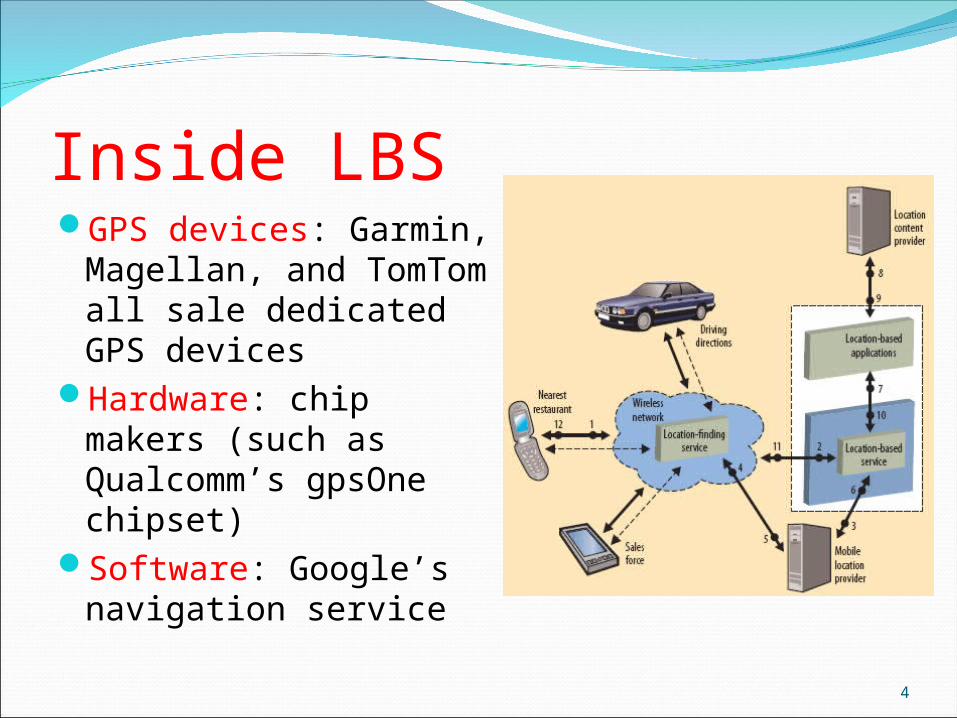
Inside LBSGPS devices: Garmin,
Magellan, and TomTom all sale dedicated GPS devices
Hardware: chip makers (such as Qualcomm’s gpsOne chipset)
Software: Google’s navigation service

5
LBS 服務分類 封閉系統 :
不具有無線資料傳輸能力,以 GPS 為代表 但是如果有臨時的道路封閉或臨時的車禍路況,就無法
即時反映在系統上 行動位置服務( Mobile Location Based Service,
MLBS )系統 :以 GSM 、 3G 或 WiFi 為資料、語音甚至多媒體的通
訊管道、並同時具有定位功能如手機的緊急求救可同時回傳位置資訊,爭取救援時效

6
Augmenting GPS with Cellular and WiFicell-based or triangulation-basedexamples:
Skyhook has LBS software to determine location via triangulation of cellular and WiFi signals
XPS: hybrid positioning system using 50 million WiFi APs to enhance accuracy
Google’s My Location: using database of cell tower positions WiFi triangulation
Microsoft may include LBS capabilities in its upcoming Windows 7.

7
GPS + WiFiGPS 導航定位功能與日常生活越來越密切,除了車載導航,許
多手機都開始內建 GPS 或 A-GPS 功能 .在個人行動應用的領域,當使用者進入騎樓、巷弄或室內時,
無法清楚收到 GPS 衛星訊號,定位功能無法發揮作用,必須尋求其他的輔助方案。
Wi-Fi 定位技術有兩種型態 一為運用已佈建完成之無線網路環境 另一種是無線網路隨同定位系統一起佈建之環境 (more costly)
龍頭大廠 Broadcom 推出升級版的行動定位服務( LBS )架構 , 將 Wi-Fi 定位功能增至 LBS 組合中 藉由偵測 Wi-Fi 無線存取點並與一個己知的地點位置資料庫比對
產生精確的定位資訊

8
Reading #2
9
Classification of Localization Methods
(week 3)

10
Cell-Identification 是最基本的行動定位技術,利用行動終端連線時所處
之基地台位置來確認用戶端位置定位準確度取決於基地台涵蓋面積及密度。
在鄉村地區,基地台稀少覆蓋範圍大,所以定位準確度很差;
而在都市地區,基地台覆蓋範圍較小,且密度較高,定位準確度相對提高許多
平均大約為 200 公尺至 2 公里。

11
Tri-angulation ( 三角定位 )利用訊號蜂巢交叉點的定位技術,當行動終端收到基
地台訊號,利用其強度計算行動終端與基地台距離,並以此距離為半徑畫出一個覆蓋圓弧 , 畫出 3 個覆蓋圓弧,其交接點處即為行動終端位置

12
TOA ( Time of Arrival ) 基於訊號傳輸時間的定位技術
需調整基地台設置,讓其時間可以同步,使相鄰基地台能夠同時監控同一行動終端的信號,隨著基地台個數增加其準確度也會提升。
TOA 基於測量信號從行動終端發送出去並到達訊號測量基地台( 3 個或更多)的時間,並將此時間轉換成距離,畫出各基地台的覆蓋圓弧,取其焦點即為行動終端位置。
為了使時間誤差不會對定位效果造成影響,基地台之間的訊號傳輸同步顯得相對重要,即使是 1 微秒的時間誤差,也會導致兩三百公尺的誤差。

13
TDOA (Time Difference of Arrival)TDOA也是基於訊號傳輸時間的
定位技術利用一個參考基地台與多個輔助
基地台收到訊號到達的時間差,再將之轉換成距離
利用雙曲線的特性,即雙曲線上的點到兩焦點距離之差為定值,帶入雙曲線的方程式中,多組雙曲線方程式聯立求解,即得到行動終端位置。
容易實現,且行動終端與基地台間無需保持精確同步

14
RSS 定位 RSS=Received Signal
Strength訓練階段 : 定位原理是行動終
端利用無線網路來收集無線信號,並藉由電播傳播模型或內外差法,得到其它收集訊號的區域,得到無線電波圖 (radio map)
追蹤定位階段 : 行動終端得到的訊號與電波圖比較,計算與模擬電波圖上相似機率,以機率最高處為行動終端位置。
優勢 : 可用於室內 , 大樓的各樓層

15
技術分類
代表性廠商 準確度 優點 缺點
Wi-Fi(RSS)
ITRI, Ekahau, Skyhook, Intel Research
室內: 1 ~5m室外: 20 ~40m
室內外皆可使用,準確度高,純軟體方案,支援標準 WiFi AP ,可判斷樓層資訊,不需更動網路設備
•開闊空間準確度較差 •需事先對環境做過校正 •環境變動會影響準確度
Wi-Fi(TDOA)
AeroScout, Hitachi AirLocation
1 ~ 5m 準確度較高 •需要專屬的網路硬體設備
Cell ID 250 ~ 1000m 不需更新現有網路系統與手機 •準確度差
A-GPS SnapTrack, SiRF
20 ~ 50m 開闊地區的準確度高,系統設備成本低
•手機需更新硬體 •手機成本高 •手機的耗電量高
TDOA TruePostion 50 ~ 150m 適用於各種手機 •系統設備成本高 •設備需做精準時間校正

16
Reading #3

17
10 Applications of LBS10 applications that make the most
of location (Wired Magazine, www.wired.com, 17.02)
(week 2)

18
1. Drive Fast, Avoid CopsTrapster (iPhone, BlackBerry)
report red-light cameras, speed cameras, cops hiding, …

19
2. Sleep Easy, We’ll Wake You UpiNap (iPhone)
Linked to Google map. As long as your GPS gets signal, it will wake you up at designated destinations.

20
3. Target and Tag Location GameJOYity
(Android)3 location-
savvy games (e.g., when a tag is within 80 feet, press trackball on your phone to execute the tag)

21
4. Call a CabCab4Me (Android)
5. Scan a Barcode, Find a DealShopSavvy (Android)
help you to find a cheaper deal somewhere else
6. See the World, Google’s EyesGoogle Earth (iPhone)

22
7. Train Your Phone to Know Its PlaceLocale (Android)
turn off your ringtone at programmed placescan also change your wallpaper and disable
WiFi at programmed areas.

23
8. Look Up! Be a Stellar Student.GoSkyWatch
(iPhone)to get the name
of a star, just point the back of your phone toward it (thanks to iPhone’s accelerometer)

24
9. Dark Alley? Call for Help.SafetyNet (Android)
Use its map to select bad neighborhood areas. When you are in these areas, your mobile
phone will enter watchdog mode.If trouble arises, just “shake” the handset, and
your phone will start sending your location to your friends/families every 30 sec., take a picture, turn on speaker, and dial 911.

25
10. Find Public Bathrooms!SitOrSquat (iPhone, BlackBerry)

26
RADAR for Indoor Localization
(week 2)
- 27 -
Introduction
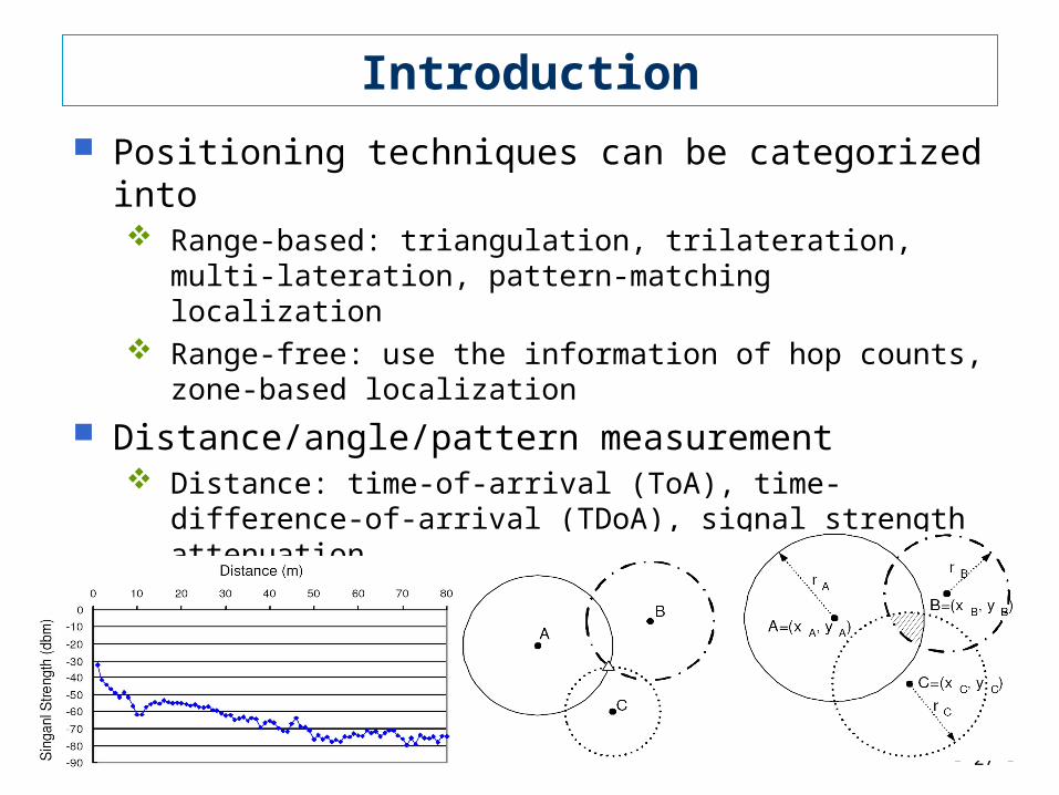
Positioning techniques can be categorized into Range-based: triangulation, trilateration, multi-lateration, pattern-
matching localization Range-free: use the information of hop counts, zone-based
localization
Distance/angle/pattern measurement Distance: time-of-arrival (ToA), time-difference-of-arrival (TDoA),
signal strength attenuation Angle: angle-of-arrival (AoA) Pattern: signal strength

- 28 -
Pattern-Matching Localization Overview
<x1, y1> 1
<x2, y2> 2...<xn, yn> n
LocationDatabase
Pattern-MatchingLocalizationAlgorithm
<x, y>
Training Phase Positioning Phaseavg. signal strength:[ i,1, i.2,…, i.m]
trainingdata
signal strength vector: [s1, s2, …, sm]
s
sreal-time
data
training location
access point (AP)
<xi, yi>i
<x1, y1>
<x2, y2>
<xn, yn>
1i

- 29 -
Challenges with Pattern-Matching Localization
Unstable signal strengths and unpredictable multipath effect
High computation cost: huge location database to match, especially in large-scale environments
Environment changes and training cost Maintenance (movement/lost of beacons) Publications
S.-P. Kuo, B.-J. Wu, W.-C. Peng, and Y.-C. Tseng, "Cluster-Enhanced Techniques for Pattern-Matching Localization Systems", IEEE Int'l Conf. on Mobile Ad-hoc and Sensor Systems (MASS), 2007
S.-P. Kuo, Y.-C. Tseng, and C.-C. Shen, "Increasing Search Space for Pattern-Matching Localization Algorithms by Signal Scrambling ", IEEE Asia-Pacific Wireless Communications Symposium, 2007.
S.-P. Kuo, Y.-C. Tseng, and C.-C. Shen, "A Scrambling Method for Fingerprint Positioning Based on Temporal Diversity and Spatial Dependency", IEEE Trans. on Knowledge and Data Engineering, submitted.
S.-P. Kuo, H.-J. Kuo, Y.-C. Tseng, and Y.-F. Lee, "Detecting Movement of Beacons in Location-Tracking Wireless Sensor Networks", IEEE VTC, 2007-Fall.

30
Reading #4
31
The BikeNet Mobile Sensing System for Cyclist Experience Mapping
Shane B. Eisenman**, Emiliano Miluzzo*, Nicholas D. Lane*Ron A. Peterson*, Gahng-Seop Ahn** and Andrew T. Campbell*
*Dartmouth College, **Columbia University
Sensys 07

32
BikeNet System Overview

33
Social Network Shared Data
BikeNet
Air Quality
CoastingNoise
Distance
Braking
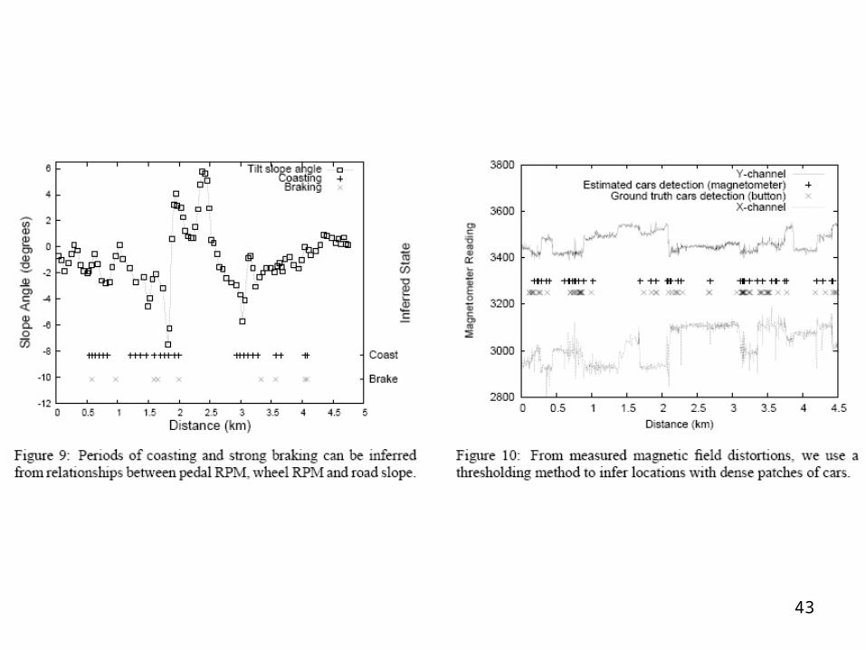
Car Density

34
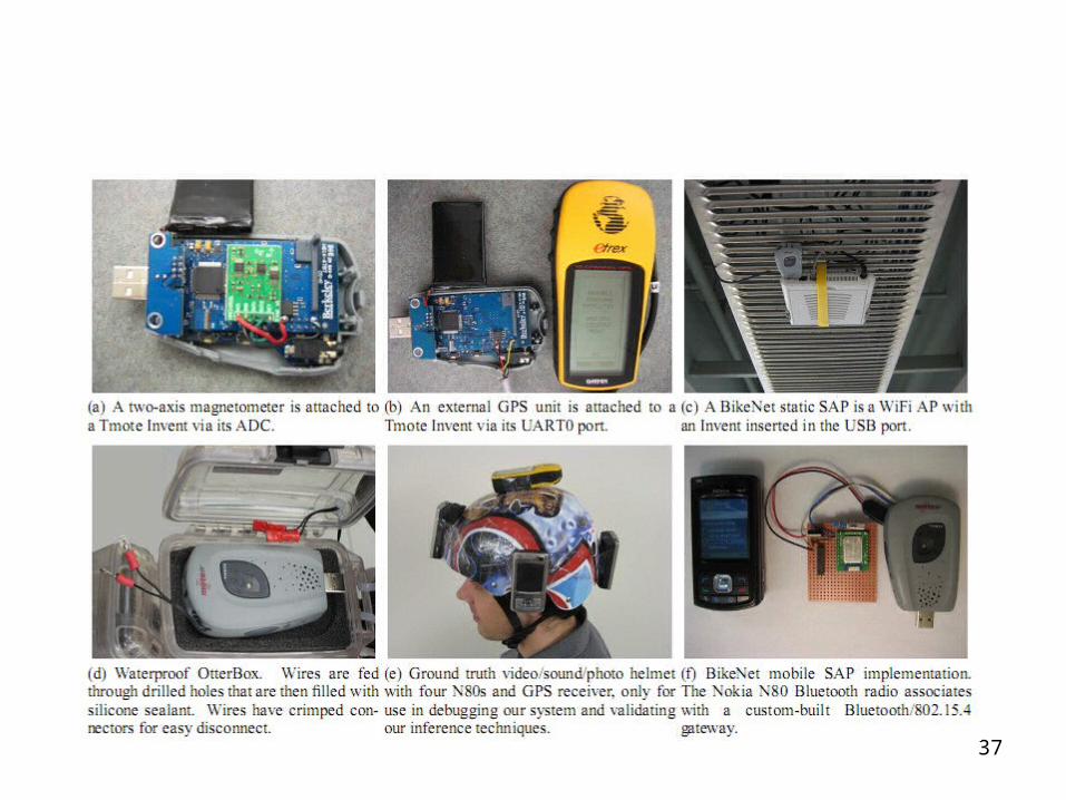
System Architecture
• Hardware– Mobile Sensor Tier
• Logical Bike Area Network (BAN)
– Sensor Access Point Tier• Static v.s. Mobile • An unmodified Tmote Invent plugged into the USB port of an
Aruba AP-70 IEEE 802.11a/b/g access point• Nokia N80 paired to a custom built Bluetooth/802.15.4
gateway (GSM/GPRS Server Tier)
– Server Tier• Backend server: Query and Visualization


37


39
System Evaluation
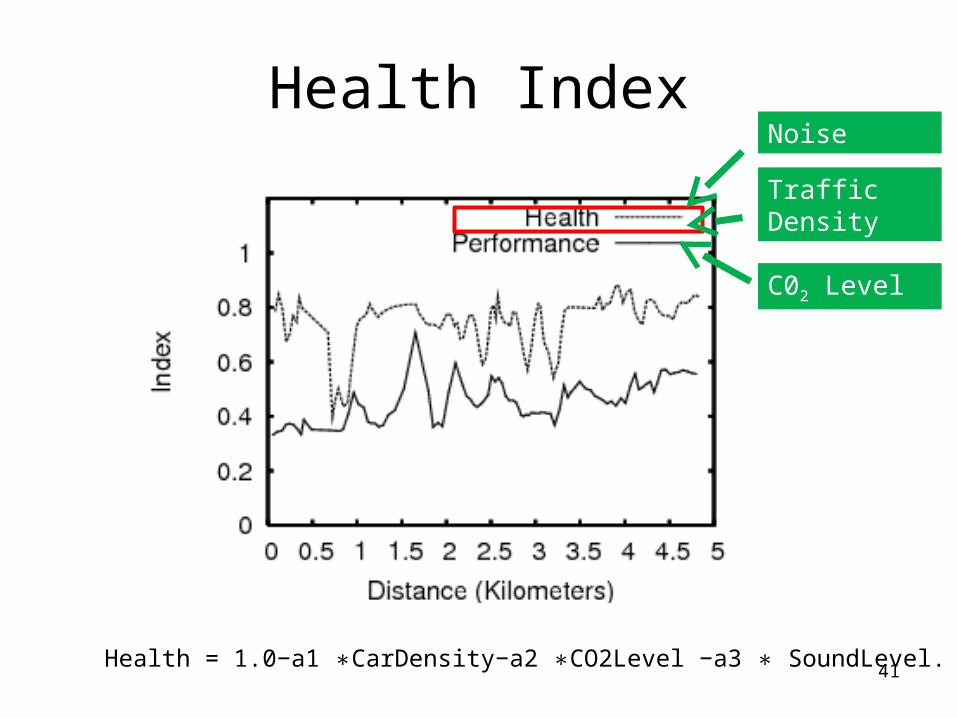
Health index = 1.0 − a1 CarDensity∗ − a2 CO∗ 2Level − a3 SoundLevel.∗
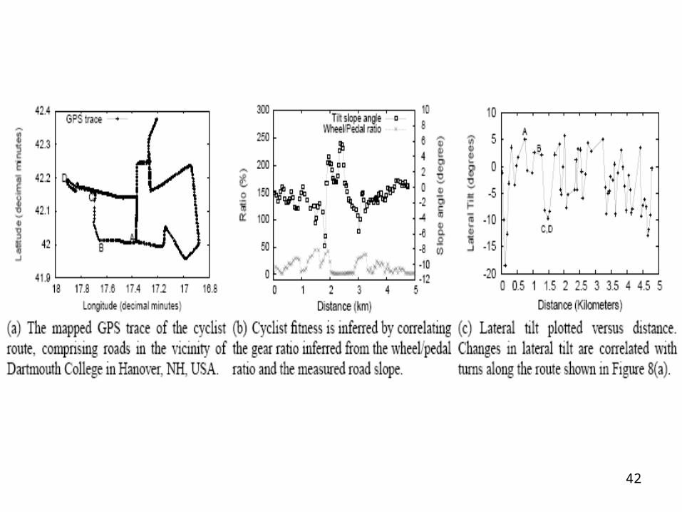
Performance index = b1 HillAngle + ∗ b2 WheelSpeed/PedalSpeed +∗ b3 Distance.∗

40
Performance IndexDistance
Duration
Speed
Path Slope
Coasting
Per f . = b1 HillAngle+b2 WheelSpeed/PedalSpeed +b3 Distance.∗ ∗ ∗
41
Health IndexNoise
C02 Level
Traffic Density
Health = 1.0−a1 CarDensity−a2 CO2Level −a3 SoundLevel.∗ ∗ ∗
42
43

44
45
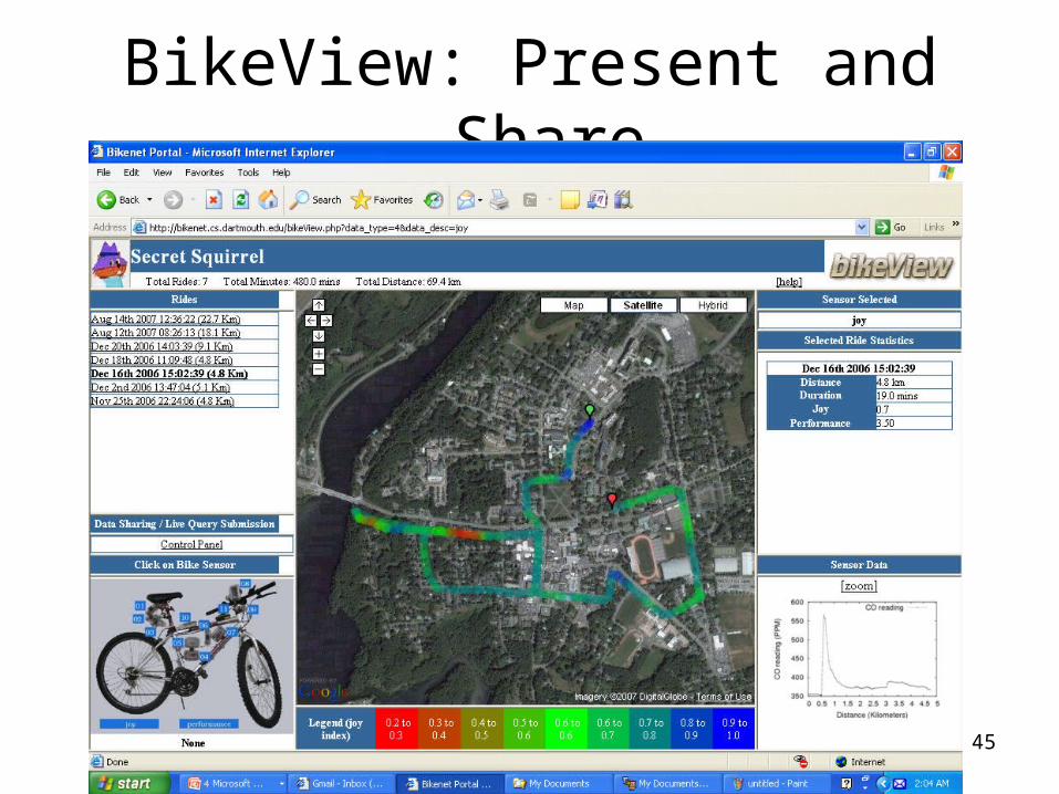
BikeView: Present and Share

46
Public Utility Sensing: CO2 Map ~ Hanover NH
47
Conclusions
• BikeNet represents the first comprehensive mobile sensing system quantifying the cyclist experience.– Performance/Fitness/Health
• Personal sensing + Social sensing
- 48 -
Indoor Wireless Localization
Signal scrambling (IEEE TKDE) Data clustering (MASS 2007) Beacon movement (VTC 2007, IEEE
TMC)
(week 4)

- 49 -
Localization:
Signal Scrambling
A Scrambling Method for Pattern-Matching Positioning Based on Temporal Diversity and Spatial Dependency

- 50 -
Difficulties
Multipath effect results in low accuracy for pattern-matchinglocalization.
Most of pattern-matching localization schemes adopt traditional classification, but ignore some unique features. Ex. Continuous samples should have high
similarity as well as diversity.
b1
b2 b3S2 S3
S1
l1
b1
b2 b3S3
S1
S2 * l3
b1
b2 b3S2
S1
S 3*
l1
l2

- 51 -
Observations
A positioning error could be generated by a small portion of interfered signal strengths. Counting on one single observation is unreliable. We can enlarge the search space by multiple
continuous observations.
Continuous observations may have some degrees of Temporal diversity: For a sequence of
observations on a beacon, diversified signal strengths may be seen.
Spatial dependency: For a serious of estimated locations, they should be close each other.
- 52 -
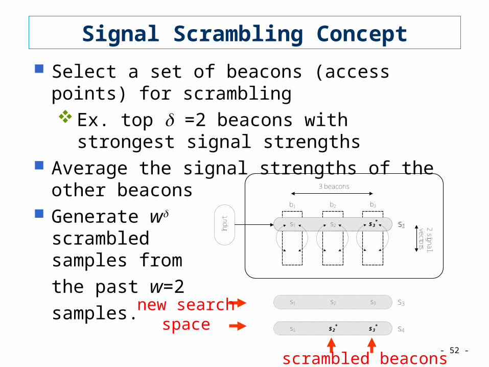
Signal Scrambling Concept
Select a set of beacons (access points) for scrambling Ex. top =2 beacons with strongest signal
strengths Average the signal strengths of the other beacons Generate w
scrambled samples from
the past w=2
samples.
2 signal vectors
3 beacons
b1 b2 b3
Inpu
ts3s1 s2
* s1s1 s2 s2s3*
s3s1 s2 s3
s4s1 s3*s2
*
new searchspace
scrambled beacons

- 53 -
Localization:
Clustering of Location Database
for pattern-matching localization in large-scale sensing field (such as a wireless city)

- 54 -
Challenges
Scalability problem when the field is large. High computation cost in the positioning phase Long system response time (critical to real-time
applications)
To reduce computation cost in the positioning phase: apply clustering technique to fragment database
into a number of sets. examine only one cluster in the positioning phase

- 55 -
Cluster Scheme Overview
<x1, y1> 1
<x2, y2> 2...<xn, yn> n
LocationDatabase
Pattern-MatchingLocalizationAlgorithm
<x, y>
C*
Training Phase Positioning Phase
signal strength vector: [s1, s2, …, sm]
avg. signal strength:[ i,1, i.2,…, i.m]
trainingdata
s
sreal-time
data
Clustering
training location
access point (AP)
<xi, yi>i
<x1, y1>
<x2, y2>
<xn, yn>
1i
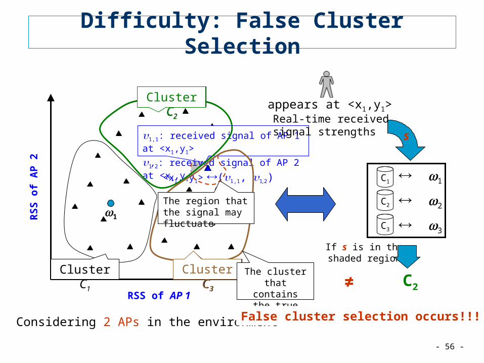
- 56 -
RSS of AP 1
RS
S o
f A
P 2
<x1, y1>(1,1, 1,2)
2
1 3
appears at <x1,y1>
Considering 2 APs in the environment
C2
If s is in theshaded region
1,1: received signal of AP 1 at <x1,y1>
1,2: received signal of AP 2 at <x1,y1>
Real-time receivedsignal strengths s
Cluster C1
Cluster C2
Cluster C3
Cluster C2
The region that the signal may fluctuate
Cluster C3 The cluster that contains the true location
≠
False cluster selection occurs!!!
C1
C2
C3
1
2
3
Difficulty: False Cluster Selection

- 57 -
Clustering Allowing Overlaps
Design new clustering techniques that allow a training location to join multiple clusters constructed by k-means. overlapping degree : the number of
clusters that a training location can join.
Complexity:
If C2 also contains <x1, y1>, the false clusterselection problem can be avoided
without overlaps(k-means)
with overlaps
average overlappingdegree
Considering 2 APs in the environment
Cluster C1 Cluster C3
Cluster C2
RSS of AP 1
RS
S o
f A
P 2
<x1, y1>(1,1, 1,2)
Cluster C2
| |( )O k
kL | |
( )O kk
L

- 58 -
Localization:
Beacon Movement Detection
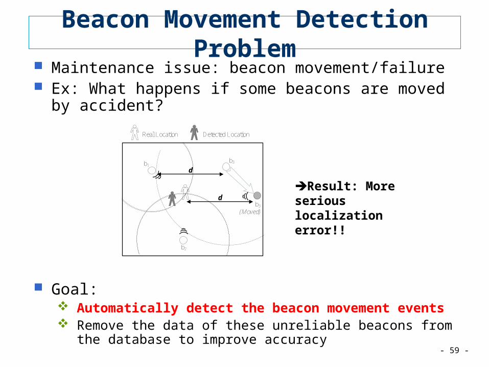
- 59 -
Beacon Movement Detection Problem Maintenance issue: beacon movement/failure Ex: What happens if some beacons are moved by accident?
Goal: Automatically detect the beacon movement events Remove the data of these unreliable beacons from the database to
improve accuracy
b2
b3b1
b3
Detected LocationReal Location
(Moved)
d
d
Result: More serious localization error!!

- 60 -
Challenges
Ambiguity
More Ambiguity:
b1
b2 is moved!
b1
b2 b3
=b1
b2 b3
Two different scenarios will induce equal observations!
b2
b1 is moved!
O = O’
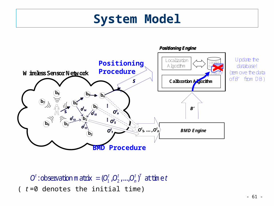
- 61 -
System Model
1 2: observation matrix ( , ,..., ) at time t t t t TnO O O O t
( t =0 denotes the initial time)
Positioning Engine
Wireless Sensor Network
LocalizationAlgorithm
LocationDatabase
b1
bnb9
b8
b7
b6
b5
b4
b3
b2
Calibration Algorithm
BMD Engine
S
S
S
Sot
14
ot13
ot12
ot15
Positioning Procedure
BMD Procedure
ot14
ot13
ot12
ot15
...
Ot1, …,Ot
n
Otn
Ot5
Ot1
......
Ot1, …,Ot
n
Otn
Ot5
Ot1
... B’B’
Positioning Engine
LocalizationAlgorithm
LocationDatabase
Calibration Algorithm
Data of B’
Update the database!
(remove the data of B’ from DB)

- 62 -
Four Movement Detection Algorithms
Neighbor-Based SchemeLocally decide if the neighboring beacons are
moved based on the neighborhood relation
Signal-Strength Variation SchemeSimilar to the first scheme. Local decision is made
according to the observed signal-strength changes.
Signal-Strength Summation SchemeThe BMD engine sums up the reported signal
strength changes
Location-Based SchemeUse a positioning technique to compute each
beacon’s location
b1
b2
o12 = Δs
b1
b2
o12 = 0 or 1
o12 = snow
b1
b2

63
Reading #5

64
Localization by RFID
ref: “LANDMARC: Indoor Location Sensing Using Active RFID”, PerCom’03by: L. Ni, Y. Liu, Y. C. Lau, and A. P. Patil

65
Some Thought
Solution 1: deploying many readers
Solution 2: deploying many tags
66
Goal of This Work
to investigate whether the RFID technology is suitable for locating objects with accuracy and cost-effectiveness.
LANDMARC: LocAtioN iDentification based on dynaMic Active RFID Calibrationfor in-building use.utilizing the concept of reference tags.

67
LANDMARC Architecture:1. readers2. fixed tags3. tracking tag

68
LANDMARC Approach (I)
In the sensing field: n readers m fixed tags u tracking tags (attached to a moving object)
Readers are configured with continuous mode. Detection range = 1 ~ 8. Signal Strength Vector of a tracking tag:
S=(S1, S2, …, Sn) Signal Strength Vector of a fixed tag i:
Fi=(θ1, θ2, …, θn)

69
LANDMARC Approach (II)
Euclidian distance between a tracking tag and the i-th fixed:
Location of the tracking tag:• pick the k fixed tags with the smallest “Euclidean
distances”• weighted location:
2
1( )
n
ji
i iE S
1
( , ) ( , )k
i i ii
x y yw x
2
21
1
1ki
i
i
i
Ew
E

70
ExperimentEnvironment

71
Environmental Factors: Daytime vs. Night
Do not see much difference in the overall accuracy.
72
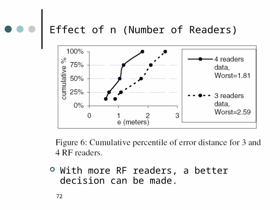
Effect of n (Number of Readers)
With more RF readers, a better decision can be made.

74
Reading #6

75
Oliver Woodman [ [email protected] ] and Rob Harle [ [email protected] ]
Pedestrian Localisation for Indoor Environments
UNIVERSITY OFCAMBRIDGE
COMPUTER LABORATORY
in Ubicomp 2008

76
Related Work
UNIVERSITY OFCAMBRIDGE
COMPUTER LABORATORY
Pedestrian Localisation for Indoor EnvironmentsOliver Woodman [ [email protected] ] and Rob Harle [ [email protected] ]
lδθ

77
System Overview
UNIVERSITY OFCAMBRIDGE
COMPUTER LABORATORY
Pedestrian Localisation for Indoor EnvironmentsOliver Woodman [ [email protected] ] and Rob Harle [ [email protected] ]
• Our system combines consists of two filters1. A PDR filter
• We use an existing PDR technique2. A particle filter for localisation
• Similar to those developed for robot localisation, except:1. Robots don’t climb stairs, but pedestrians do - Need to extend to 3D2. In existing literature, robot localisation is usually tested in a relatively small
area. We deploy our system in a large (8725m2) three-storey building
PDR Filter
Localisation Particle Filter2.5D Map
(a,ω)
Steps (l,δθ,δz)
Absolute positions (x,y,z,θ)
Low level
High level
Xsens IMU
100Hz
~1Hz

78
PDR Filter
UNIVERSITY OFCAMBRIDGE
COMPUTER LABORATORY
Pedestrian Localisation for Indoor EnvironmentsOliver Woodman [ [email protected] ] and Rob Harle [ [email protected] ]
• Input : Foot mounted IMU measurements (a,ω) (100Hz)• Output : Step events (l,δθ,δz)
• Inertial measurements are integrated using the standard strapdown navigation equations• Zero velocity updates used to reduce drift from cubic-in-time to linear-in-distance-
travelled
• See “Pedestrian Tracking with Shoe-Mounted Inertial Sensors” [E. Foxlin] for more details
79
Representing Building Constraints – 2.5D Maps
UNIVERSITY OFCAMBRIDGE
COMPUTER LABORATORY
Pedestrian Localisation for Indoor EnvironmentsOliver Woodman [ [email protected] ] and Rob Harle [ [email protected] ]
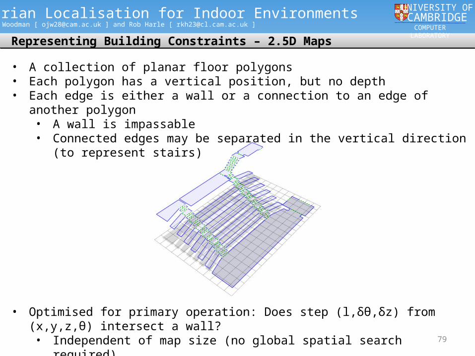
• Optimised for primary operation: Does step (l,δθ,δz) from (x,y,z,θ) intersect a wall?• Independent of map size (no global spatial search required)• Intersections computed in 2D rather than 3D
• A collection of planar floor polygons• Each polygon has a vertical position, but no depth• Each edge is either a wall or a connection to an edge of another polygon
• A wall is impassable• Connected edges may be separated in the vertical direction (to represent stairs)
80
Localisation Particle Filter
UNIVERSITY OFCAMBRIDGE
COMPUTER LABORATORY
Pedestrian Localisation for Indoor EnvironmentsOliver Woodman [ [email protected] ] and Rob Harle [ [email protected] ]
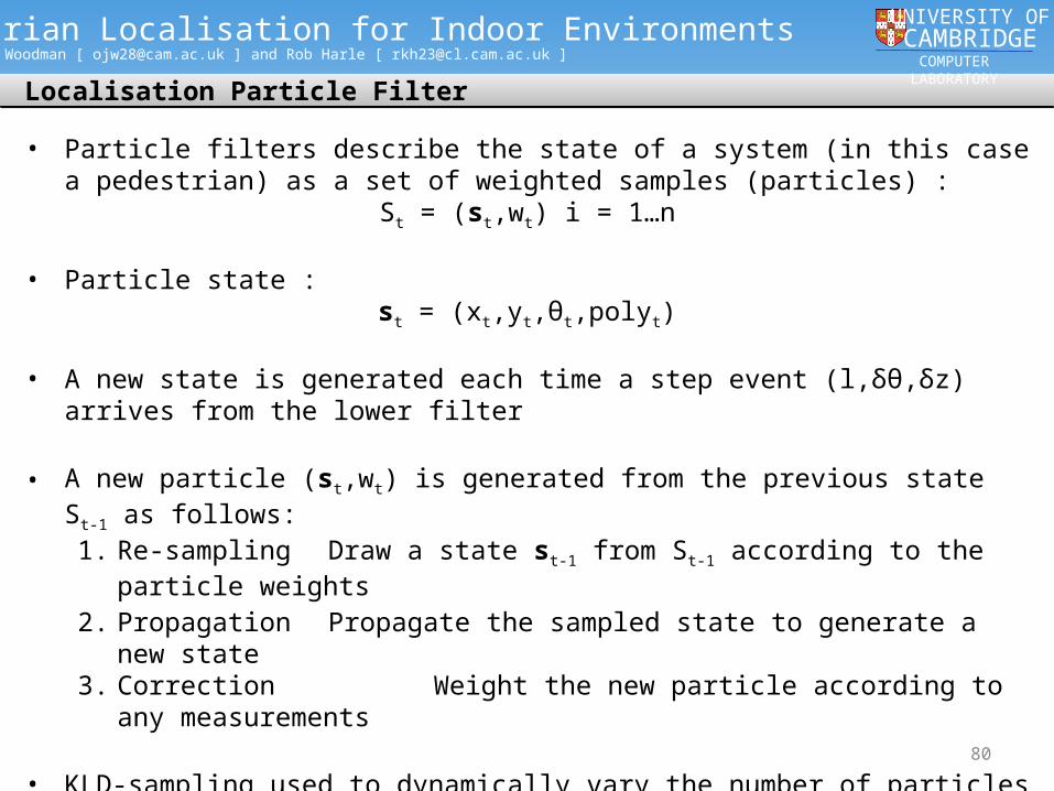
• Particle filters describe the state of a system (in this case a pedestrian) as a set of weighted samples (particles) :
St = (st,wt) i = 1…n
• Particle state : st = (xt,yt,θt,polyt)
• A new state is generated each time a step event (l,δθ,δz) arrives from the lower filter
• A new particle (st,wt) is generated from the previous state St-1 as follows:1. Re-sampling Draw a state st-1 from St-1 according to the particle weights
2. Propagation Propagate the sampled state to generate a new state 3. Correction Weight the new particle according to any
measurements
• KLD-sampling used to dynamically vary the number of particles generated at each update

81
Localisation Particle Filter
UNIVERSITY OFCAMBRIDGE
COMPUTER LABORATORY
Pedestrian Localisation for Indoor EnvironmentsOliver Woodman [ [email protected] ] and Rob Harle [ [email protected] ]
• Propagation :1. Perturb step heading and length by noise
(l’,δθ’) = (l + X, δθ + Y)2. Compute new heading and position
θt = θt-1 + δθ’xt = xt-1 + l’cosθt
yt = yt-1 + l’sinθt
3. Update floor polygon• Test for intersections between the step vector and the edges of polyt-1
• Intersection tests preformed in 2D• Operation speed is independent of map size - no global lookups
• Correction :• If step intersects wall : wt = 0
• Else : Use δz (from the step event) as a measurement• Height change according to map : δzpoly = Height(polyt) - Height(polyt-1)• Set particle weight : wt = N0,σh(| δz - δzpoly|)
• Allows localisation to occur quickly when the user climbs or descends stairs

82
Typical WiFi Localization Using Particle Filter
• 3 Stage– Re-sampling (Initial) stage– Sampling & Random stage– Weighting stage
82

83
Initial Stage
83
5%
5%
5%
5%5%
5%
5%
5% 5%
5%
5%
5%
5%5%
5%
5%
5%
5%
5%
5%

8484
Sampling Stage
5%
5%
5%
5%
5% 5%
5%
5%
5%
5%
5%5%
5%
5%
5%
5%
5%
5%
5%
5%

8585
Random Stage
85

8686
Weighting Stage
Location Server
0.15
5%*0.15
0.08
5%*0.08
0.02
5%*0.02
Pattern MatchingEstimation

8787
Weighting Stage
6%
8%
10% 13%
11% 8% 6% 3% 6%
5% 5% 4%
2% 2%
1%
3%
4%
1%
1%
1%
Particle FilterEstimation
8888
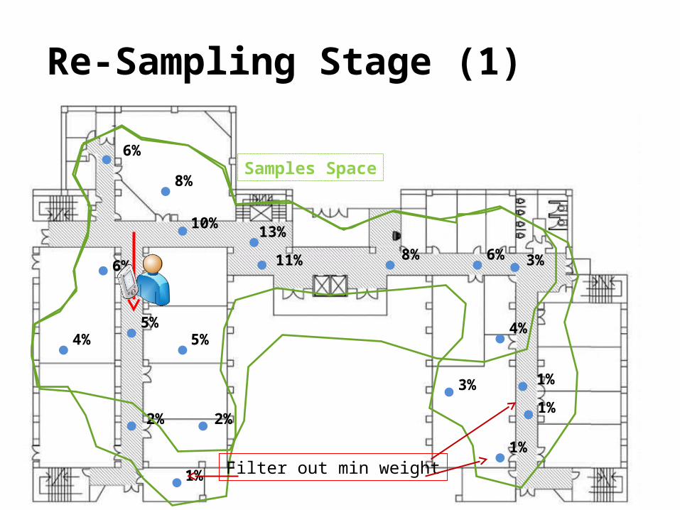
Re-Sampling Stage (1)
6%
8%
10% 13%
11% 8% 6% 3% 6%
5% 5% 4%
2% 2%
1%
3%
4%
1%
1%
1%
Filter out min weight
Samples Space

8989
Sampling Stage and Random (2)
Samples Space

9090
Weighting Stage (3)
Samples Space 6%
1%
30%
1%
1%
1% 1%
1%
1%
1%
1%
1%
1%
2%
2% 2% 2%
2%
2%
8%
6%
7%
4% 4%
4%
4%

9191
After a period of time

9292
Re-Sampling Stage (1)
Samples Space
Sampling area
9393
Sampling Stage and Random(2)
Samples Space

9494
Sampling Stage and Random(2)

9595
Weighting Stage(3)
12%
11%
12%
33%
17%
9%
7%5%
5%

9696
Pedestrian Localisation for Indoor Environments
UbiComp 2008

9797
Re-Sampling Stage (1)
Samples Space
Sampling area

9898
Sampling Stage and Random(2)
Samples Space
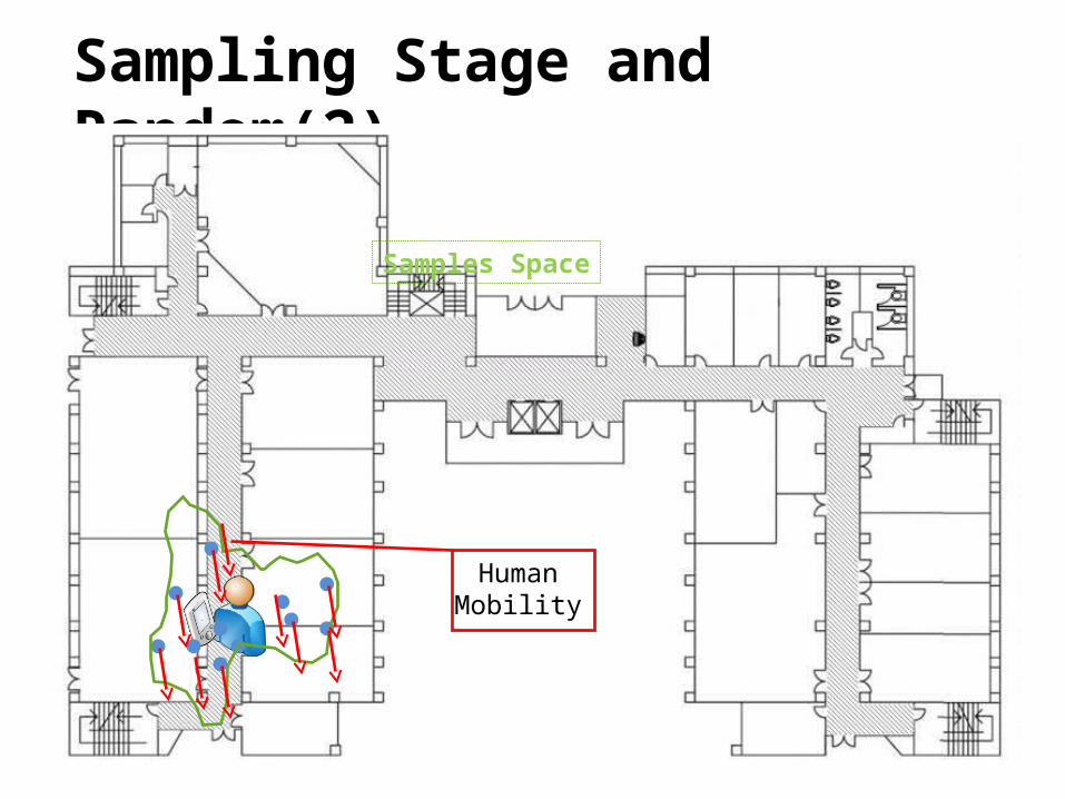
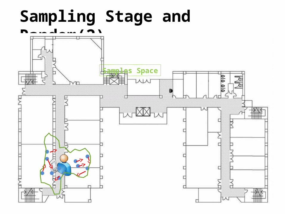
9999
Sampling Stage and Random(2)
Samples Space
HumanMobility

100100
Sampling Stage and Random(2)
Illegal Path

101101
Weighting Stage(3)
Center of mass
102
Demonstration Videos
UNIVERSITY OFCAMBRIDGE
COMPUTER LABORATORY
Pedestrian Localisation for Indoor EnvironmentsOliver Woodman [ [email protected] ] and Rob Harle [ [email protected] ]
See Two Demo Videos

103
Conclusions and Future Work
UNIVERSITY OFCAMBRIDGE
COMPUTER LABORATORY
Pedestrian Localisation for Indoor EnvironmentsOliver Woodman [ [email protected] ] and Rob Harle [ [email protected] ]
Conclusions
• We have developed a pedestrian localisation system for indoor environments• Foot mounted IMU used to obtain “step” measurements• Localisation techniques developed for robots extended to handle multiple floors• WiFi used to constrain the initial prior
• Position error <0.73m 95% of the time in a typical office environment• Such a system could enable the deployment of location aware applications in large
buildings, where installation of a high accuracy absolute location system is either too expensive or too impractical
Future Work
• Better use of WiFi :• Use WiFi throughout localisation and tracking, rather than just at the start• Use RSSI values to generate tighter constraints
• Use of magnetometer measurements to constrain the heading• Although overcoming magnetic disturbances will be a big problem