1. key: (a) 1. sol: 2. 3. 4. solgfweb.s3.amazonaws.com/iespapers/2017/ec-ies-2017-objective...
TRANSCRIPT

ESE-2017 |EC| Objective Paper-II
ICP–Intensive Classroom Program IES-Live Internet Based Classes DLP All India IES-Test Series Leaders in IES Preparation 65+ Centers across India
© All rights reserved by Gateforum Educational Services Pvt. Ltd. No part of this booklet may be reproduced or utilized in any form without the written permission.
1
1. Consider the following statements:
The output of a linear circuit, driven with a
sine wave at a frequency f, is itself a sine wave
1. at the same frequency
2. with chance of changed amplitude
3. with chances of changed amplitude and
phase
Which of the above statements is/are correct?
(A) 1 and 2 (B) 1 only
(C) 1 and 3 (D) 2 only
Key: (C)
Sol: For a linear system, if the input is a sinusoidal
signal then the output is also a sinusoidal
signal with same frequency but the amplitude
and phase of the output may varie.
2. Consider the following statements:
The main contribution to photoconduction
is by
1. the generation of electron and hole pair
by a photon
2. a donor electron jumping into the
conduction band because of a photon’s
energy
3. a valence electron jumping into an
acceptor state because of a photon’s
energy
Which of the above statements is/are correct?
(A) 1 only (B) 2 only
(C) 3 only (D) 1, 2 and 3
Key: (A)
Sol: In photoconduction, due to illumination
covalent bonds will be broken and
electron and hole pair is generated. Thus
only (1) is correct.
3. Thermal runaway is not possible in FET
because as the temperature of the FET
increases
(A) Mobility decreases
(B) trans-conductance increases
(C) drain current increases
(D) trans-conductance decreases
Key: (A)
Sol: As the temperature of FET
increases, mobility decreases.
4. For JFET, the drain current ID is
(A)
(B)
(C)
(D)
Key: (D)
Sol: For JFET, the drain correct is
2
GsD Dss
P
VI I 1
V
= −
(Shockley’s equation)
5. For n-channel depletion MOSFET, the
highest trans-conductance gain for small
signal is at
(A) (B)
(C) (D)
Key: (A)
Sol: For n-channel deletion MOSFET, the
trans-conductance formulae is
Gsm mo
P
Vg g 1
V
= −
Where mg is highest trans-
conductance at GSV 0V=
6. The n-p-n transistor made of silicon has a DC
base bias voltage 15 V and an input base
1
2GS
DSS
P
VI 1
V
−
GSDSS
p
VI 1
V
−
3
2GS
DSS
P
VI 1
V
−
2
GSDSS
P
VI 1
V
−
GSV 0V= GS pV V=
GS pV V= GS pV V= −
ESE-2017 |EC| Objective Paper-II
ICP–Intensive Classroom Program IES-Live Internet Based Classes DLP All India IES-Test Series Leaders in IES Preparation 65+ Centers across India
© All rights reserved by Gateforum Educational Services Pvt. Ltd. No part of this booklet may be reproduced or utilized in any form without the written permission.
2
resistor . Then the value of the base
current into the transistor is
(A) (B)
(C) (D)
Key: (C)
Sol: B BV 15V;R 150k;= =
B 3
15 0.7I 95.3 A
150 10
−= = µ
×
7. A signal may have frequency components
which lie in the range of 0.001 Hz to 10 Hz.
Which one of the following types of
couplings should be chosen in a multistage
amplifier designed to amplify the signal?
(A) Capacitor coupling
(B) Direct coupling
(C) Transformer coupling
(D) Double-tuned transformer coupling
Key: (B)
Sol: For low frequency signal (0.001 Hz
to 10 Hz), direct coupling is used in
multistage amplifier.
8. If an input impedance of op-amp is finite,
then which one of the following statements
related to virtual ground is correct?
(A) Virtual ground condition may exist.
(B) Virtual ground condition cannot exist.
(C) In case of op-amp, virtual ground
condition always exists.
(D) Cannot make a valid declaration.
Key: (B)
Sol: If input impedance of Op- amplifier is finite
(for non ideal Op-amp), virtual ground
condition cannot exist.
9. Hysteresis is desirable in a Schmitt trigger
because
(A) energy is to be stored/discharged in
parasitic capacitances
(B) effects of temperature variations would
be compensated
(C) devices in the circuit should be allowed
time for saturation and de-saturation
(D) it would prevent noise from causing
false triggering
Key: (D)
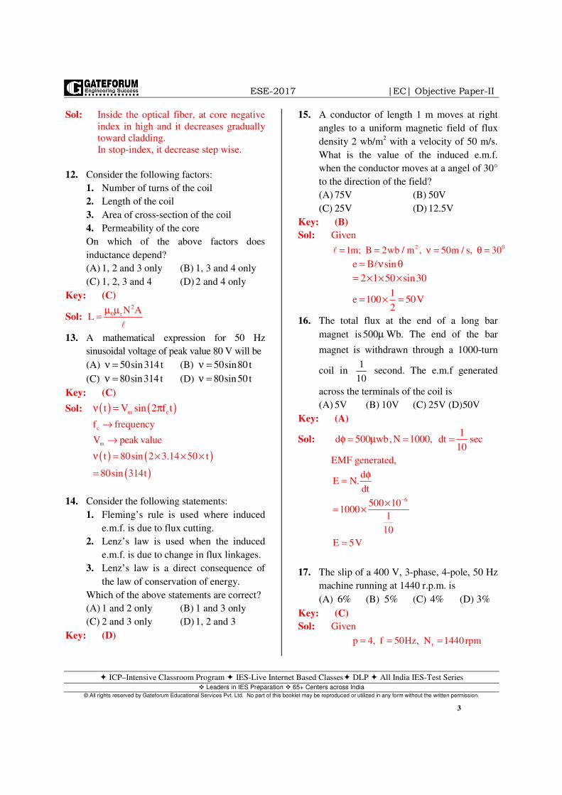
10. In a photoconductive cell, the resistance of
the semiconductor material varies with
intensity of incident light
(A) directly (B) inversely
(C) exponentially (D) logarithmically
Key: (A)
Sol: Illumination characteristics of a typical
photo conductive cell
11. In graded index multimode optical fiber the
refractive index of the core is
(A) uniform across its radial distance,
except for the cladding
(B) maximum at the fiber axis and
decreases stepwise towards the cladding
(C) maximum at the fiber axis and decreases
gradually towards the cladding
(D) maximum at the fiber axis and increases
stepwise towards the cladding
Key: (C)
150kΩ
0.953 Aµ 9.53 Aµ
95.3 Aµ 953 Aµ
BI
150k
15V
100
10
1.0
0.1 1 10 100 1000
2Illumination in LUMENS / m
cell
( )R in km
ESE-2017 |EC| Objective Paper-II
ICP–Intensive Classroom Program IES-Live Internet Based Classes DLP All India IES-Test Series Leaders in IES Preparation 65+ Centers across India
© All rights reserved by Gateforum Educational Services Pvt. Ltd. No part of this booklet may be reproduced or utilized in any form without the written permission.
3
Sol: Inside the optical fiber, at core negative
index in high and it decreases gradually
toward cladding.
In stop-index, it decrease step wise.
12. Consider the following factors:
1. Number of turns of the coil
2. Length of the coil
3. Area of cross-section of the coil
4. Permeability of the core
On which of the above factors does
inductance depend?
(A) 1, 2 and 3 only (B) 1, 3 and 4 only
(C) 1, 2, 3 and 4 (D) 2 and 4 only
Key: (C)
Sol: 2
0 r N AL
µ µ=
13. A mathematical expression for 50 Hz
sinusoidal voltage of peak value 80 V will be
(A) (B)
(C) (D)
Key: (C)
Sol: ( ) ( )m ct V sin 2 f tν = π
( ) ( )( )
c
m
f frequency
V peak value
t 80sin 2 3.14 50 t
80sin 314t
→
→
ν = × × ×
=
14. Consider the following statements:
1. Fleming’s rule is used where induced
e.m.f. is due to flux cutting.
2. Lenz’s law is used when the induced
e.m.f. is due to change in flux linkages.
3. Lenz’s law is a direct consequence of
the law of conservation of energy.
Which of the above statements are correct?
(A) 1 and 2 only (B) 1 and 3 only
(C) 2 and 3 only (D) 1, 2 and 3
Key: (D)
15. A conductor of length 1 m moves at right
angles to a uniform magnetic field of flux
density 2 wb/m2 with a velocity of 50 m/s.
What is the value of the induced e.m.f.
when the conductor moves at a angel of 30°
to the direction of the field?
(A) 75V (B) 50V
(C) 25V (D) 12.5V
Key: (B)
Sol: Given 2 01m; B 2wb / m , 50m / s, 30= = ν = θ =
e B sin= ν θ
2 1 50 sin30= × × ×
1
e 100 50V2
= × =
16. The total flux at the end of a long bar
magnet is Wb. The end of the bar
magnet is withdrawn through a 1000-turn
coil in second. The e.m.f generated
across the terminals of the coil is
(A) 5V (B) 10V (C) 25V (D)50V
Key: (A)
Sol: 1
d 500 wb,N 1000, dt sec10
φ = µ = =
EMF generated,
6
dE N.
dt
500 101000
1
10
E 5V
−
φ=
×= ×
=
17. The slip of a 400 V, 3-phase, 4-pole, 50 Hz
machine running at 1440 r.p.m. is
(A) (B) (C) (D)
Key: (C)
Sol: Given
rp 4, f 50Hz, N 1440rpm= = =
50sin314 tν = 50sin80 tν =80sin314 tν = 80sin50 tν =
500µ
1
10
6% 5% 4% 3%
ESE-2017 |EC| Objective Paper-II
ICP–Intensive Classroom Program IES-Live Internet Based Classes DLP All India IES-Test Series Leaders in IES Preparation 65+ Centers across India
© All rights reserved by Gateforum Educational Services Pvt. Ltd. No part of this booklet may be reproduced or utilized in any form without the written permission.
4
slip, s r
s
N Ns 100
N
−= ×
Synchronous speed,
s
120f 120 50N 1500 rpm
p 4
×= = =
Slip, 1500 1440
s 1001500
−= ×
0.04 100
4%
= ×
=
18. A 500 HP, 440 V, 3-phase, 50 Hz induction
motor runs at 950 r.p.m. when on full load
with a synchronous speed of 1000 r.p.m.
For this condition, the frequency of the
rotor current will be
(A) 4.0 Hz (B) 3.5 Hz
(C) 2.5 Hz (D) 2.0 Hz
Key: (C)
Sol: 500Hp, 440V, 3 , 50Hz− φ induction
motor.
r sN 950 rpm, N 1000 rpm= =
Frequency of rotor current,
r
f s.f=
s r
s
N Ns slip 100
N
1000 950
950
−= = ×
−=
r
0.05
f 0.05 50 2.5Hz
=
= × =
19. By adding resistance in the rotor circuit of a
slip ring induction motor, the starting
current
(A) as well as torque reduce
(B) as well as torque increase
(C) reduces but the starting torque increases
(D) increases but the starting torque
decreases
Key: (C)
Sol: By increasing the rotor resistance, it not
only reduces the stator current, but also
the rotor current too. This implies that
starting current of motor is reduced and
starting torque is increased due to
improvement in power factor.
20. Consider the following statements with
regards to an induction motor:
1. Maximum torque is independent of
rotor resistance.
2. Starting torque is maximum when rotor
resistance equals rotor reactance.
3. Torque is very sensitive to any changes
in supply voltage.
Which of the above statements are correct?
(A) 1 and 2 only (B) 1 and 3 only
(C) 2 and 3 only (D) 1, 2 and 3
Key: (D)
Sol: We have maximum torque equation as:
2
2max
s 2
E3T . N m
2 N 2X= −
π
So from the above equation, we can
infer that maximum torque is
independent of resistance.
Starting torque is maximum (i.e at s = 1)
when rotor resistance is equal to rotor
reactance i.e., 2 2
R X= and
Now, 2
E α supply voltage V
2
2st 2 2
2 2
KV RT
R X∴ =
+
∴ st
T Vα
The torque is very sensitive to any
changes in supply voltage. Hence all
the given 3 statements are correct.
21. A transformer has 2% resistance and 5%
reactance. What is its voltage regulation at
full load with 0.8 p.f. lagging?
(A) 5.3% (B) 4.6%

ESE-2017 |EC| Objective Paper-II
ICP–Intensive Classroom Program IES-Live Internet Based Classes DLP All India IES-Test Series Leaders in IES Preparation 65+ Centers across India
© All rights reserved by Gateforum Educational Services Pvt. Ltd. No part of this booklet may be reproduced or utilized in any form without the written permission.
5
(C) 0.53% (D) 0.46%
Key: (B)
Sol: Voltage regulation for lagging power
factor loads is
%V %R cos %Xsin= φ + φ
( )( )1
%R 2%;%X 5%;cos 0.8;
sin sin cos 0.8 0.6−
= = φ =
φ = =
%V 2 0.8 5 0.6 4.6%= × + × =
22. A voltage is generated across a
piezoelectric material, 0.5 cm thick,
subjected to an impact of 5 N/m2. The
voltage coefficient of the material is
The magnitude of the
voltage generated will be
(A) 2300 V (B) 1650 V
(C) 1150 V (D) 575 V
Key: (D)
Sol: E gF
VE
d
V gFd
=
=
=
Where g is Coefficient = 23 kV-m/N
F is force = 5N/m2
D is thickness = 0.5 cm = 20.5 10 m−×
3 2V 23 10 5 0.5 10 575V−= × × × × =
23. The ‘residual resistivity’ of a metal is
(A) due to lattice vibrations at high
temperature
(B) due to photon scattering at high
temperature
(C) temperature-dependent
(D) temperature-independent
Key: (D)
24. Electrical conductivity, thermal conductivity
and magnetic properties of ceramic material are
(A) very high all the time
(B) very low all the time
(C) dependent on the material
(D) ascertainable, instance to instance
Key: (D)
Sol: In ceramic materials all properties are
constant till particular temperature after
that it will change.
25. Laminated insulation, coated with varnish,
is a staple adoption in transformer
assemblage in order to
(A) reduce the reluctance of the magnetic
path
(B) minimize losses due to eddy currents
(C) increase the reluctance of the magnetic
path
(D) increase the effect of eddy current
Key: (B)
Sol: Eddy current loss depends on thickness.
26. When a ferromagnetic substance is magnetized
there are marginal diminutions in its linear
dimensions. This phenomenon is called
(A) hysteresis
(B) magnetostriction
(C) diamagnetism
(D) dipolar relaxation
Key: (B)
27. When the working temperature becomes
more than the curie temperature, a
ferromagnetic material becomes a
(A) diamagnetic material
(B) paramagnetic material
(C) ferromagnetic material
(D) Mu-material
Key: (B)
28. Compared to other materials, a material
with a wider hysteresis loop has
23kV m N.−

ESE-2017 |EC| Objective Paper-II
ICP–Intensive Classroom Program IES-Live Internet Based Classes DLP All India IES-Test Series Leaders in IES Preparation 65+ Centers across India
© All rights reserved by Gateforum Educational Services Pvt. Ltd. No part of this booklet may be reproduced or utilized in any form without the written permission.
6
(A) lower permeability, higher retentivity
and higher coercivity
(B) higher permeability, lower retentivity
and higher coercivity
(C) lower permeability, higher retentivity
and lower reluctance
(D) lower permeability, lower retentivity
and lower residual magnetism
Key: (A)
Sol: Wider hysteresis will have more losses.
29. Which of the following material is used in
light-emitting diodes?
(A) Gallium arsenide sulphate
(B) Gallium arsenide phosphide
(C) Gallium chromate phosphide
(D) Gallium phosphide sulphate
Key: (B)
Sol: In Light emitting materials we use
compound semiconductors (combination
of III rd and V group) which are direct
band gap materials.
30. Consider the following methods in nano
particle synthesis:
1. Bottom –up 2. Top-down
3. side-by-side
Which of these methods is/are slow and
does/do not conduce to large-scale
production?
(A) 1 only (B) 2 only
(C) 3 only (D) 1, 2 and3
Key: (A)
Sol: Top-Bottom is slow and not suitable for
large scale production.
31. Consider the following statements:
1. Type-I superconductors undergo abrupt
transition to the normal state above a
critical magnetic field.
2. Type-II superconductors are highly
technologically useful super conductors
because the incidence of a second
critical field in them is useful in the
preparation of high field
electromagnets.
Which of the above statements is/are
correct?
(A) 1 only (B) 2 only
(C) Both 1 and 2 (D) Neither 1 nor 2
Key: (C)
Sol: For electromagnets there should be residual
magnetism. In TYPE –II residual
magnetism exists for all cases.
32. Consider the following statements:
1. Metal conductors have more R at higher
temperatures.
2. Tungsten can be used as a resistance
wire.
3. A superconductive material is one
which has practically zero resistance.
Which of the above statements are correct?
(A) 1 and 2 only (B) 1 and 3 only
(C) 2 and 3 only (D) 1, 2 and 3
Key: (B)
33. Consider the following statements
regarding precision in measurements of a
quantity:
1. Precision is the measure of the spread
of the incident errors.
2. Precision is independent of the
realizable correctness of the
measurement
3. Precision is usually described in terms
of number of digits used in the
measurement by a digital instrument.
Which of the above statements are correct?
(A) 1, 2 and 3 (B) 1 and 2 only
(C) 1 and 3 only (D) 2 and 3 only

ESE-2017 |EC| Objective Paper-II
ICP–Intensive Classroom Program IES-Live Internet Based Classes DLP All India IES-Test Series Leaders in IES Preparation 65+ Centers across India
© All rights reserved by Gateforum Educational Services Pvt. Ltd. No part of this booklet may be reproduced or utilized in any form without the written permission.
7
Key: (A)
34. Consider the following statements in
connection with deflection-type and null-
type instruments:
1. Null-type instruments are more accurate
than the deflection-type ones.
2. Null-type of instrument can be highly
sensitive compared to a deflection-type
instrument.
3. Under dynamic conditions, null-type
instruments are less preferred to
deflection-type instruments.
4. Response is faster in null-type
instruments as compared to deflection-
type instruments.
Which of the above statements are correct?
(A) 1, 2 and 3 (B) 1, 2 and 4
(C) 1, 3 and 4 (D) 2, 3 and 4
Key: (A)
Sol: Null-type instruments are preferable
because of its superior accuracy.
Null-type instruments are more
sensitive then deflection type.
35. A voltmeter having a sensitivity of
reads 100 V on its 150 V scale
when connected across a resistor of
unidentified specifications in series with a
milliammeter. When the milliammeter
reads 5 mA, the error due to the loading
effect of the voltmeter will be nearly
(A) 13% (B) 18%
(C) 23% (D) 33%
Key: (A)
Sol: Sensitivity 1000 / V= Ω , full scale
= 150 V
Voltmeter resistance
( )vR 1000 / V 150V 150k= Ω × = Ω
Voltmeter current
( )v
m v
100I 0.67mA
150k
I I I
5mA 0.67mA
4.33 mA
= =Ω
= −
= −
=
m
100VR 23.09k
4.33mA
100VR 20k
5mA
= = Ω
= = Ω
Error due to loading effect of voltmeter is
20 23.09100
23.09
13.38%
−= ×
= −
36. Consider the following statements:
Sphere gap method of voltage measurement
is used
1. for measuring r.m.s value of a high
voltage
2. for measuring peak value of a high
voltage
3. as the standard for calibration purposes
Which of the above statements are correct?
(A) 1 and 2 only (B) 2 and 3 only
(C) 1 and 3 only (D) 1, 2 and 3
Key: (B)
37. High frequency (in the MHz range) and low
amplitude (in the mV range) signals are
best measured using
(A) VTVM with a high impedance probe
(B) CRO
(C) moving-iron instrument
(D) digital multimeter
Key: (B)
38. In scintillation coating applications, shields
of which material are generally placed
around the photomultiplier tube to
1000 VΩ

ESE-2017 |EC| Objective Paper-II
ICP–Intensive Classroom Program IES-Live Internet Based Classes DLP All India IES-Test Series Leaders in IES Preparation 65+ Centers across India
© All rights reserved by Gateforum Educational Services Pvt. Ltd. No part of this booklet may be reproduced or utilized in any form without the written permission.
8
overcome interference effects of electrons
deflected from their normal path?
(A) Ferromagnetic
(B) Mu-metal magnetic
(C) Electromagnetic
(D) Dielectric
Key: (C)
39. A PMMC instrument if connected directly
to measure alternating current, it indicates
(A) the actual value of the subject AC
quantity
(B) zero reading
(C) of the scale value where the
pointer rests
(D) of the scale value where the
pointer rests
Key: (B)
Sol: Average torque produced is zero for AC
supply. Hence, no deflection is
produced.
40. Which of the following are measured by
using a vector voltmeter?
1. Amplifier gain and phase shift
2. Filler transfer function
3. Complex insertion loss
Select the correct answer using the code
given below.
(A) 1 and 2 only (B) 1 and 3 only
(C) 2 and 3 only (D) 1, 2 and 3
Key: (D)
41. In a transistor, the base current and
collector current are, respectively,
and 1.75 mA. The value of is nearly
(A) 0.91 (B) 0.97 (C) 1.3 (D) 1.7
Key: (B)
Sol: Given B C
3
C
6
B
I 60 A;I 1.75 mA
I 1.75 1029.17
I 60 10
29.170.97
1 1 29.17
−
−
= µ =
×β = = =
×
βα = = =
+ β +
42. A liquid flows through a pipe of 100 mm
diameter at a velocity of 1 m/s. If the
diameter is guaranteed within +1% and the
velocity is known to be within of
measured value, the limiting error for the
rate of flow is
(A) (B)
(C) (D)
Key: (D)
Sol: D 100 mm,V 1m / s= =
With generated errors;
D 100mm 1%;V 1 3%= + = ±
Rate of flow ( ) 3Q V A m / sec= ×
2Q V D
4
π= ×
lnQ ln V ln 2ln D4
π= + +
1 1 dV 2 dD
0 .Q V dQ D dQ
Q V D100 100 2 100
Q V D
3% 2 1% 5%
= + +
∆ ∆ ∆× = × + ×
= + × = ±
43. A digit digital voltmeter is accurate to
of reading digits. What is the
percentage error, when the voltmeter reads
0.10 V on its 10 V range?
(A) 0.025% (B) 0.25%
(C) 2.05% (D) 20.5%
Key: (D)
Sol: Reading on 10V range = 0.1 V
Error = ( )0.5% of rea ding 2digits± ±
1
2
3
2
60 Aµ
α
3%±
1%± 2%±3%± 5%±
13
2
0.5%± 2±
ESE-2017 |EC| Objective Paper-II
ICP–Intensive Classroom Program IES-Live Internet Based Classes DLP All India IES-Test Series Leaders in IES Preparation 65+ Centers across India
© All rights reserved by Gateforum Educational Services Pvt. Ltd. No part of this booklet may be reproduced or utilized in any form without the written permission.
9
Resolution of 1
32
DVM in 20 V range
3
200.01V
2 10= =
×
So error
( ) ( )0.50.1V 2 0.01 2.0205V
100
= ± × + × = ± Therefore error in reading
0.0205V
1000.1V
20.5%
= ± ×
= ±
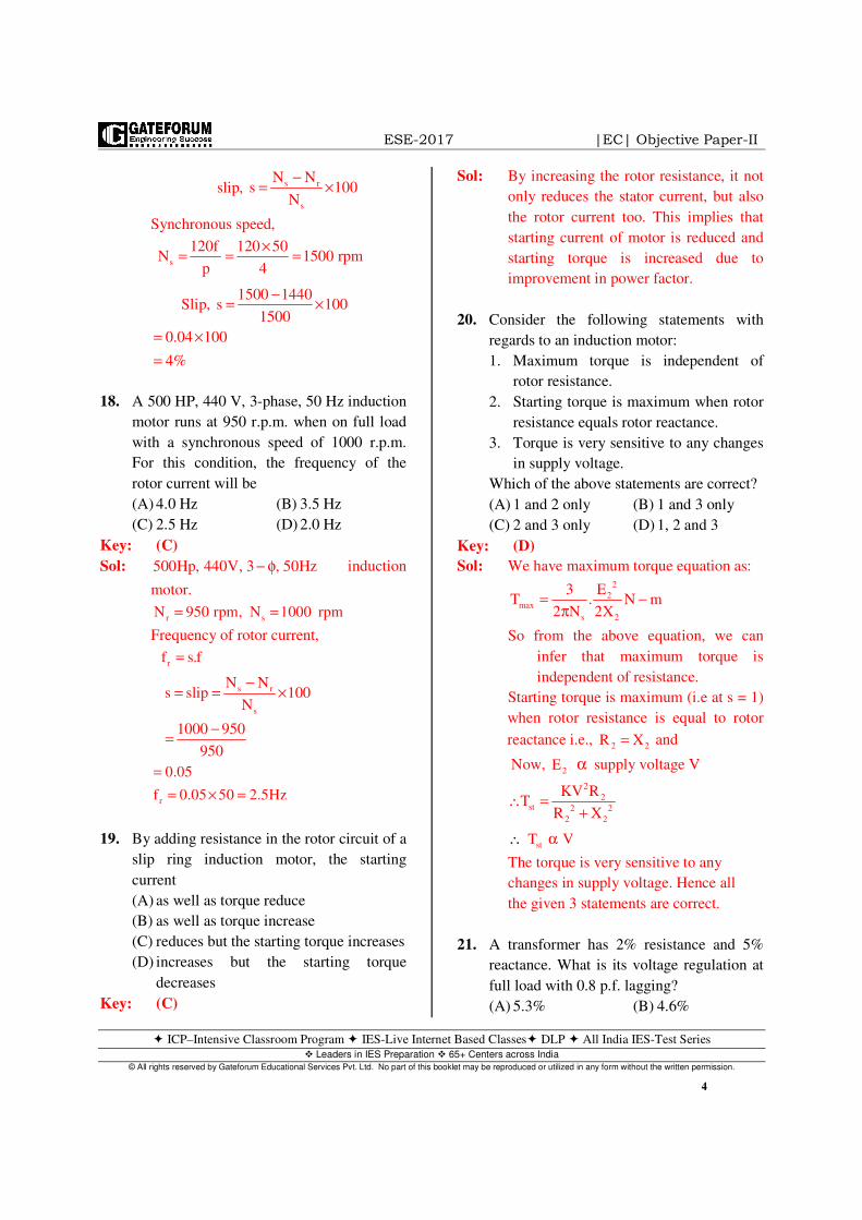
44. The simplest and most common method of
reducing any ‘effect of inductive coupling’
between measurement and power circuits is
achieved by using
(A) a screen around the entire measurement
circuit
(B) twisted pairs of cable
(C) capacitor (s) to be connected at the
power circuit
(D) capacitor(s) to be connected at the
measurement circuit
Key: (B)
45. A capacitance transducer uses two quartz
diaphragms of area separated by
a distance 3.5 mm. The capacitance is 370
pF. When a pressure of is
applied, the deflection is 0.6 mm. The
capacitance at this pressure would be
(A) 619 pF (B) 447 pF
(C) 325 pF (D) 275 pF
Key: (B)
Sol: Capacitance,
( )
1 2
2 1
22 1
1
AC
d
1i.e,C
d
C d
C d
d 3.5C C 370pF 447pF
d 3.5 0.6
ε=
∝
=
= × = × =−
46. Consider the following statements regarding
Time-Division Multiplexing (TDM):
1. The information from different
measuring points is transmitted serially
on the same communication channel.
2. It involves transmission of data samples
rather than continuous data transmission.
3. It is especially useful when
telemetering fast-changing, high
bandwidth data.
Which of the above statements are valid in
respect to TDM?
(A) 1, 2 and 3 (B) 1 and 3 only
(C) 1 and 2 only (D) 2 and 3 only
Key: (A)
Sol: All are the benefits of TDM.
47. Consider the following regarding essential
functional operations of a digital data
acquisition system:
1. Handling of analog signals
2. Converting the data to digital form and
handling it
3. Making the measurement
4. Internal programming and telemetry
Which of the above are valid in the stated
context?
(A) 1, 2, 3 and 4 (B) 1, 3 and 4 only
2750mm
2900KN m
ESE-2017 |EC| Objective Paper-II
ICP–Intensive Classroom Program IES-Live Internet Based Classes DLP All India IES-Test Series Leaders in IES Preparation 65+ Centers across India
© All rights reserved by Gateforum Educational Services Pvt. Ltd. No part of this booklet may be reproduced or utilized in any form without the written permission.
10
(C) 1, 2 and 3 only (D) 2 and 4 only
Key: (A)
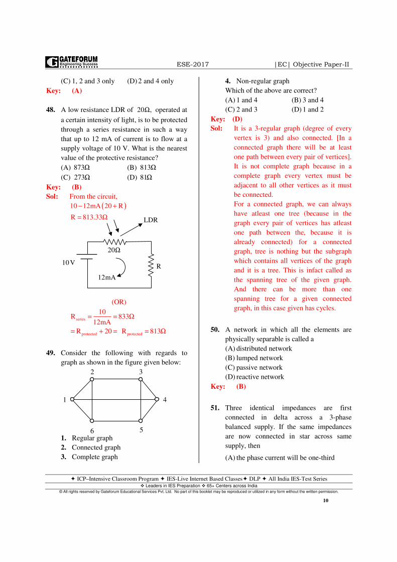
48. A low resistance LDR of operated at
a certain intensity of light, is to be protected
through a series resistance in such a way
that up to 12 mA of current is to flow at a
supply voltage of 10 V. What is the nearest
value of the protective resistance?
(A) (B)
(C) (D)
Key: (B)
Sol: From the circuit,
( )10 12mA 20 R
R 813.33
− +
= Ω
(OR)
series
protected protected
10R 833
12mA
R 20 R 813
= = Ω
= + = = Ω
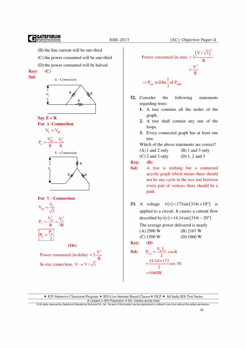
49. Consider the following with regards to
graph as shown in the figure given below:
1. Regular graph
2. Connected graph
3. Complete graph
4. Non-regular graph
Which of the above are correct?
(A) 1 and 4 (B) 3 and 4
(C) 2 and 3 (D) 1 and 2
Key: (D)
Sol: It is a 3-regular graph (degree of every
vertex is 3) and also connected. [In a
connected graph there will be at least
one path between every pair of vertices].
It is not complete graph because in a
complete graph every vertex must be
adjacent to all other vertices as it must
be connected.
For a connected graph, we can always
have atleast one tree (because in the
graph every pair of vertices has atleast
one path between the, because it is
already connected) for a connected
graph, tree is nothing but the subgraph
which contains all vertices of the graph
and it is a tree. This is infact called as
the spanning tree of the given graph.
And there can be more than one
spanning tree for a given connected
graph, in this case given has cycles.
50. A network in which all the elements are
physically separable is called a
(A) distributed network
(B) lumped network
(C) passive network
(D) reactive network
Key: (B)
51. Three identical impedances are first
connected in delta across a 3-phase
balanced supply. If the same impedances
are now connected in star across same
supply, then
(A) the phase current will be one-third
20 ,Ω
873Ω 813Ω273Ω 81Ω
2 3
41
6 5
LDR
R
20Ω
12mA
10 V
ESE-2017 |EC| Objective Paper-II
ICP–Intensive Classroom Program IES-Live Internet Based Classes DLP All India IES-Test Series Leaders in IES Preparation 65+ Centers across India
© All rights reserved by Gateforum Educational Services Pvt. Ltd. No part of this booklet may be reproduced or utilized in any form without the written permission.
11
(B) the line current will be one-third
(C) the power consumed will be one-third
(D) the power consumed will be halved
Key: (C)
Sol:
Say Z = R
For ∆ -Connection
L phV V=
2 2ph L
V VP
R R∆ = =
For Y - Connection
Lph
VV
3=
2 2ph L
Y
V VP
R 3R= =
Y
PP
3
∆=
(Or)
Power consumed (in delta) 2V
3.R
=
In star connection, V V / 3→
Power consumed (in star) ( )2
2
V / 33
R
V
R
=
=
star delta
1P willbe of P
3⇒
52. Consider the following statements
regarding trees:
1. A tree contains all the nodes of the
graph.
2. A tree shall contain any one of the
loops.
3. Every connected graph has at least one
tree.
Which of the above statements are correct?
(A) 1 and 2 only (B) 1 and 3 only
(C) 2 and 3 only (D) 1, 2 and 3
Key: (B)
Sol: A tree is nothing but a connected
acyclic graph which means there should
not be any cycle in the tree and between
every pair of vertices there should be a
path.
53. A voltage is
applied to a circuit. It causes a current flow
described by
The average power delivered is nearly
(A) 2500 W (B) 2167 W
(C) 1500 W (D) 1060 W
Key: (D)
Sol: m mavg
V IP .cos
2
14.14 173cos 30
2
= θ
×=
=1060W.
( ) ( )t 173sin 314t 10ν = + °
( ) ( )i t 14.14sin 314t 20= − °
LVR
R
R
Connection∆ −
R
R
R
LV
Y Connection−

ESE-2017 |EC| Objective Paper-II
ICP–Intensive Classroom Program IES-Live Internet Based Classes DLP All India IES-Test Series Leaders in IES Preparation 65+ Centers across India
© All rights reserved by Gateforum Educational Services Pvt. Ltd. No part of this booklet may be reproduced or utilized in any form without the written permission.
12
54. Consider the following statements with
respect to a parallel R-L-C circuit:
1. The bandwidth of the circuit decreases
if R is increased.
2. The bandwidth of the circuit remains
same if L is increased.
3. At resonance, input impedance is a real
quantity.
4. At resonance, the magnitude of the
input impedance attains its minimum
value.
Which of the above statements are correct?
(A) 1, 2 and 4 (B) 1, 3 and 4
(C) 2, 3 and 4 (D) 1, 2 and 3
Key: (D)
Sol: • 1
BWRC
=
• ‘L’ does not have any influence on BW
in parallel RLC
• at resonance, Z = R, Real quantity
55. What is the admittance matrix for a two-
port network shown in the figure given
below?
(A) (B)
(C) (D)
Key: (*)
Sol: admittance matrix
[ ] 1impedancematrix
−=
Impedance matrix 15 10
10 15
=
Admittance matrix
15 101
10 15125
− = −
(None of the option matching).
56. A two-port network is characterized by
Its A, B, C and D parameters are,
respectively
(A) 2, 3, 6 and 9 (B) 2, -3, 10 and -9
(C) 3, 2, -9 and 6 (D) 3, -2, 9 and -6
Key: (B)
Sol: 1 1 2 1 2 2 2 2I 3V 4V I 9I 10V CV DI= + ⇒ = + = −
2 22 1 2 1 2 2 2 2
6I 4V6I 2V 4V V 3I 2V AV BI
2
C 10 A 2
D 9 B 3.
+= − ⇒ = = + = −
= =
⇒ = − = −
57. A unit-step voltage is applied at t = 0 to a
series R-L circuit with zero initial
condition. Then
(A) it is possible for the current to be
oscillatory
(B) the voltage across the resistor at
is zero
(C) the voltage across the resistor at
is zero
(D) the resistor current eventually falls
to zero
Key: (B)
Sol:
15 5
5 15
15 51
5 15200
− −
5 15
15 5
200 51
15 20200
1 1 2
2 1 2
I 3V 4V
6I 2V 4V
= +
= −
t 0+=
t 0−=
5 Ω 5 Ω
10 Ω
R
Lu(t) −i
+
ESE-2017 |EC| Objective Paper-II
ICP–Intensive Classroom Program IES-Live Internet Based Classes DLP All India IES-Test Series Leaders in IES Preparation 65+ Centers across India
© All rights reserved by Gateforum Educational Services Pvt. Ltd. No part of this booklet may be reproduced or utilized in any form without the written permission.
13
( ) ( ) ( ) ( )( )
( )
( )
( )
Rt
L
Rt
L
Rt
L
i t i i 0 i e
1 10 eRR
11 e
R
1iR
V 0.
−
−
−
= ∞ + − ∞
= + −
= −
∞ =
∞ =
at T = 0+ inductor is open circuit hence
( )2 RV 1V,V 0 0V+= = .
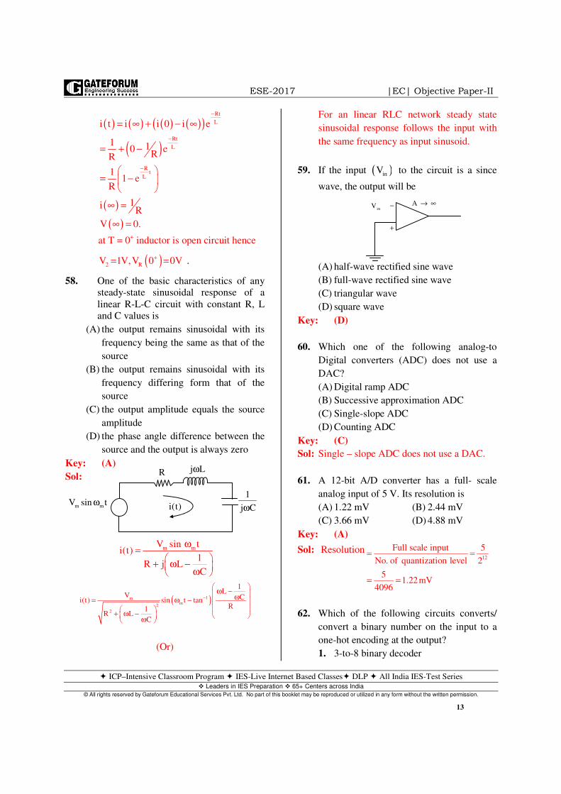
58. One of the basic characteristics of any
steady-state sinusoidal response of a
linear R-L-C circuit with constant R, L
and C values is
(A) the output remains sinusoidal with its
frequency being the same as that of the
source
(B) the output remains sinusoidal with its
frequency differing form that of the
source
(C) the output amplitude equals the source
amplitude
(D) the phase angle difference between the
source and the output is always zero
Key: (A)
Sol:
m mV sin ti(t)
1R j L
C
ω=
+ ω − ω
( )1mm
2
2
1L
V Ci(t) sin t tanR1
R LC
−
ω − ω= ω − + ω − ω
(Or)
For an linear RLC network steady state
sinusoidal response follows the input with
the same frequency as input sinusoid.
59. If the input to the circuit is a since
wave, the output will be
(A) half-wave rectified sine wave
(B) full-wave rectified sine wave
(C) triangular wave
(D) square wave
Key: (D)
60. Which one of the following analog-to
Digital converters (ADC) does not use a
DAC?
(A) Digital ramp ADC
(B) Successive approximation ADC
(C) Single-slope ADC
(D) Counting ADC
Key: (C)
Sol: Single – slope ADC does not use a DAC.
61. A 12-bit A/D converter has a full- scale
analog input of 5 V. Its resolution is
(A) 1.22 mV (B) 2.44 mV
(C) 3.66 mV (D) 4.88 mV
Key: (A)
Sol: Resolution 12
Full scale input 5
No. of quantization level 2
51.22mV
4096
= =
= =
62. Which of the following circuits converts/
convert a binary number on the input to a
one-hot encoding at the output?
1. 3-to-8 binary decoder
( )inV
+
−inV A → ∞
R j Lω
1
j Cωm mV sin tω i(t)

ESE-2017 |EC| Objective Paper-II
ICP–Intensive Classroom Program IES-Live Internet Based Classes DLP All India IES-Test Series Leaders in IES Preparation 65+ Centers across India
© All rights reserved by Gateforum Educational Services Pvt. Ltd. No part of this booklet may be reproduced or utilized in any form without the written permission.
14
2. 8-to-3 binary decoder
3. Comparator
Select the correct answer using the code
given below.
(A) 1 only (B) 2 only
(C) 3 only (D) 1, 2 and 3
Key: (A)
Sol: 3 8× binary decoder
One hot encoding means only those with
a single high (1) bit and all other low (0).
63. The simplification in minimal sum of
product (SOP) of
Using K-maps is
(A) (B)
(C) (D)
Key: (D)
Sol:
Y AC BD= +
64. A circuit outputs a digit in the form of 4
bits.0 is represented by 0000, 1 is
represented by 0001, … 9 by 1001. A
combinational circuit is to be designed
which takes these 4 bits as input and output
as 1, if the digit is and 0 otherwise. If
only AND, OR and NOT gates may be
used, what is the minimum number of gates
required?
(A) 4 (B) 3 (C) 2 (D) 1
Key: (B)
Sol:
F A B.D BC= + +
AND – gates = 2
OR – gate = 1
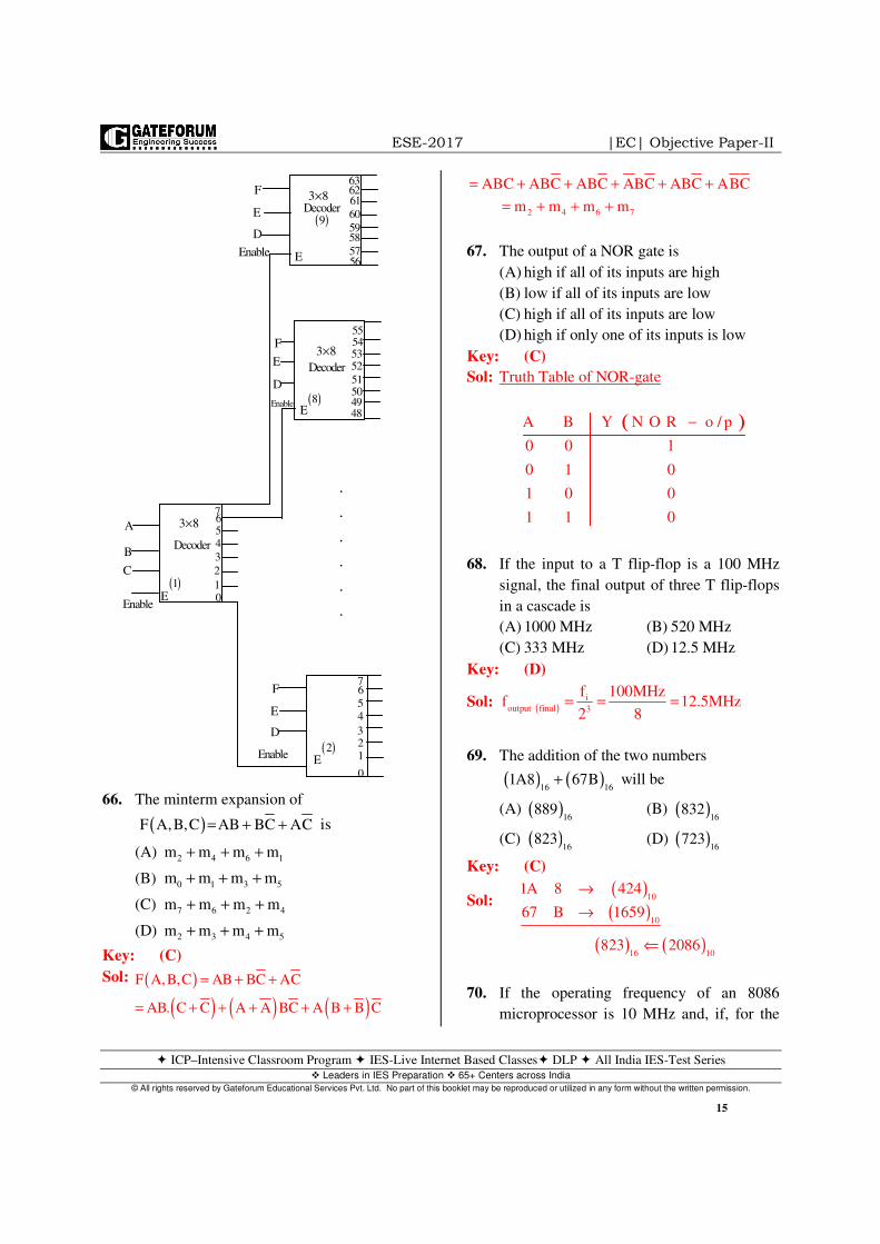
65. How many 3-to-8 line decoders with and
enabler input are needed to construct a
6-to-64 line decoder without using any
other logic gates ?
(A) 11 (B) 10 (C) 9 (D) 8
Key: (C)
Sol: 3 to 8 decoder → 6 to 64 decoder
6 4 8
8 8
8 1 9
+
+ =
(Or)
( )( ) ( )m d
Y F A,B,C,D
0,2,3,6,7 8,10,11,15
=
= ∑ +∑
Y AC BD= + Y AC BD= +
Y AC BD= + Y AC BD= +
5,≥
0 0 0 0
0 1 1 1
x x x x
1 1 x x
ABCD
00
01
11
10
00 01 11 10
AC
BD
1 1 1
1 1
x
x x x
I n p u t s O u t p u t s
A B C D F
0 0 0 0 0
0 0 0 1 0
0 0 1 0 0
0 0 1 1 0
0 1 0 0 0
0 1 0 1 1
0 1 1 0 1
0 1 1 1 1
1 0 0 0 1
1 0 0 1 1
ABCD
00
01
11
10
00 01 11 10
ESE-2017 |EC| Objective Paper-II
ICP–Intensive Classroom Program IES-Live Internet Based Classes DLP All India IES-Test Series Leaders in IES Preparation 65+ Centers across India
© All rights reserved by Gateforum Educational Services Pvt. Ltd. No part of this booklet may be reproduced or utilized in any form without the written permission.
15
66. The minterm expansion of
is
(A)
(B)
(C)
(D)
Key: (C)
Sol: ( )
( ) ( ) ( )F A,B,C AB BC AC
AB. C C A A BC A B B C
= + +
= + + + + +
ABC ABC ABC ABC ABC ABC= + + + + +
2 4 6 7m m m m= + + +
67. The output of a NOR gate is
(A) high if all of its inputs are high
(B) low if all of its inputs are low
(C) high if all of its inputs are low
(D) high if only one of its inputs is low
Key: (C)
Sol: Truth Table of NOR-gate
( )A B Y N O R o / p
0 0 1
0 1 0
1 0 0
1 1 0
−
68. If the input to a T flip-flop is a 100 MHz
signal, the final output of three T flip-flops
in a cascade is
(A) 1000 MHz (B) 520 MHz
(C) 333 MHz (D) 12.5 MHz
Key: (D)
Sol: ( )i
output final 3
f 100MHzf 12.5MHz
2 8= = =
69. The addition of the two numbers
will be
(A) (B)
(C) (D)
Key: (C)
Sol: ( )( )
10
10
1A 8 424
67 B 1659
→
→
( ) ( )16 10
823 2086⇐
70. If the operating frequency of an 8086
microprocessor is 10 MHz and, if, for the
( )F A,B,C AB BC AC= + +
2 4 6 1m m m m+ + +
0 1 3 5m m m m+ + +
7 6 2 4m m m m+ + +
2 3 4 5m m m m+ + +
( ) ( )16 16
1A8 67B+
( )16
889 ( )16
832
( )16
823 ( )16
723
F
E
D
E
3 8×Decoder
636261
60
5958
5756
( )9
55545352
51504948
7654
3
2
10
76
5
4
321
0
Decoder
( )8
Decoder
3 8×
E
3 8×
E( )1
A
B
C
F
E
D
Enable
F
E
D
Enable
EnableE
( )2
.
.
.
.
.
.
Enable
ESE-2017 |EC| Objective Paper-II
ICP–Intensive Classroom Program IES-Live Internet Based Classes DLP All India IES-Test Series Leaders in IES Preparation 65+ Centers across India
© All rights reserved by Gateforum Educational Services Pvt. Ltd. No part of this booklet may be reproduced or utilized in any form without the written permission.
16
given instruction, the machine cycle
consists of 4 T-states, what will be the time
taken by the machine cycle to complete the
execution of that same instruction when
three wait states are inserted?
(A) (B)
(C) (D)
Key: (B)
Sol: 6
1 1T 0.1 s
f 10 10= = = µ
×
Total number of states = 4T+3T=7T
7 0.1 s 0.7 s× µ = µ
71. The probability density function
where x is a random
variable whose allowable value range is
from
The CDF for this
function for is
(A) (B)
(C) (D)
Key: (B)
Sol: The CDF is basically the integration of pdf.
( ) ( )x
X xF x f d−∞
= α α∫
Since x 0≥
( )0 x
b b
X
0
0 x
b b
0
bx
F x ae d ae d
a ae e
b b
a a ae
b b b
α − α
−∞
α − α
−∞
−
= α + α
= +−
= + + −
∫ ∫
bx bxa a a
2 e 2 eb b b
− − = − = −
72. Consider the following statements
regarding electrical properties of ceramic
materials :
1. They are practically non conductors at
lower temperatures.
2. Ordinary glass and silicates in molten
state are dependable as electrical non-
conductors.
3. They offer high resistance to current
transmission and get heated soon when
conducting electric current.
Which of the above statements are correct ?
(A) 1 and 2 only (B) 1 and 3 only
(C) 2 and 3 only (D) 1, 2 and 3
Key: (C)
73. If primary and secondary windings of core-
type single-phase transformer are wound on
non-magnetic core, then the
1. efficiency of the transformer will
decrease
2. efficiency of the transformer will
increase
3. transformer regulation will increase
4. transformer regulation will decrease
Which of the above possibilities are realized?
(A) 1 and 4 (B) 1 and 3
(C) 2 and 3 (D) 2 and 4
Key: (C)
Sol: As core get removed hence no core loss and
power loss is reduced and efficiency
increases and regulation also increases.
74. In the case of small BJT model with
common emitter, the collector current ic is
1.3 mA, when the collector-emitter voltage
is of 2.6 V. The output conductance of
the circuit is
(A) (B)
(C) (D)
0.4 sµ 0.7 sµ
7 sµ 70 sµ
( ) b xF x ae ,
−=
x to x .= −∞ = +∞
x 0≥
bxae
b( )bxa2 e
b
−−
bxae
b− ( )bxa
2 eb
−− +
ceν
2.0mΩ 2.0m
0.5mΩ 0.5m
ESE-2017 |EC| Objective Paper-II
ICP–Intensive Classroom Program IES-Live Internet Based Classes DLP All India IES-Test Series Leaders in IES Preparation 65+ Centers across India
© All rights reserved by Gateforum Educational Services Pvt. Ltd. No part of this booklet may be reproduced or utilized in any form without the written permission.
17
Key: (D)
Sol: 3cce
ce
i 1.3mA 1g 10
v 2.6 2
0.5m
−= = = ×
=
75. An FM broadcasting radio station transmits
signals of frequency 100 MHz with a power
of 10 kW. The bandwidth of the modulation
signal is from 100 Hz to 1.5 kHz. If the
maximum deviation set by the FCC, is
75 kHz, the range of the modulation index is
(A) 100 to 750 (B) 100 to 250
(C) 50 to 750 (D) 50 to 250
Key: (C)
Sol: Modulation index m
fP
f
∆=
If 3
m
75 10f 100Hz, 750
100
×= β = =
If 3
m 3
75 10f 1.5 kHz 50
1.5 10
×= β = =
×
76. An amplitude-modulated amplifier has a
radio frequency output of 60W at 100%
modulation. The internal loss in the
modulator is 6W. What is the unmodulated
carrier power?
(A) 33W (B) 36W
(C) 40W (D) 44W
Key: (D)
Sol: Power at the input of modulator
( )66W 60W 6W loss= +
Total power
2
T C C
C C
1P P 1 66 P 1
2 2
66 2P P 44 watt
3
µ = + ⇒ = +
×⇒ = ⇒ =
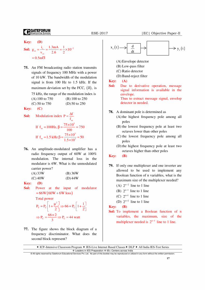
77. The figure shows the block diagram of a
frequency discriminator. What does the
second block represent?
(A) Envelope detector
(B) Low-pass filter
(C) Ratio detector
(D) Band-reject filter
Key: (A)
Sol: Due to derivative operation, message
signal information is available in the
envelope.
Thus to extract message signal, envelop
detector in needed.
78. A dominant pole is determined as
(A) the highest frequency pole among all
poles
(B) the lowest frequency pole at least two
octaves lower than other poles
(C) the lowest frequency pole among all
poles
(D) the highest frequency pole at least two
octaves higher than other poles
Key: (B)
79. If only one multiplexer and one inverter are
allowed to be used to implement any
Boolean function of n variables, what is the
maximum size of the multiplexer needed?
(A) line to 1 line
(B) line to 1 line
(C) line to 1 line
(D) line to 1 line
Key: (B)
Sol: To implement a Boolean function of n
variables, the maximum, size of the
multiplexer needed is n 12 − line to 1 line.
( ),δ
n 22 −
n 12 −
n 12 +
n 22 +
d
dt( )cx t ( )cy t
ESE-2017 |EC| Objective Paper-II
ICP–Intensive Classroom Program IES-Live Internet Based Classes DLP All India IES-Test Series Leaders in IES Preparation 65+ Centers across India
© All rights reserved by Gateforum Educational Services Pvt. Ltd. No part of this booklet may be reproduced or utilized in any form without the written permission.
18
80. What is the minimum b
0
E
Nrequired to
achieve a spectral efficiency of 6bps/Hz ?
(A) 5.2 (B) 5.3
(C) 10.5 (D) 15.8
Key: (C)
Sol: Channel capacity
[ ]2
b
o
b2
o
C B
b
o
6
b
o
C Blog 1 SNR
E .Csignal powerSNR
noise power N .B
EC Clog 1 .
B N B
E 2 1
N C B
EC 2 1Now 5 bps Hz 10.5
B N 6
= +
= =
⇒ = +
−⇒ =
−= ⇒ = =
81. What is the required bandwidth of a PCM
system for 256 quantization levels when 48
telephone channels, each band-limited to
4kHz, are to be time-division multiplexed
by this PCM?
(A) 6.246 MHz (B) 3.464 MHz
(C) 3.072 MHz (D) 1.544 MHz
Key: (C)
Sol: Bandwidth required snf=
No. of bits, 2n log 256 8= =
sf → sampling frequency
Since nothing in given on sampling
frequency, we assume sampling
frequency as 2fm.
sf 8000 samples sec.=
Total data rate 48 8 8000 3,072,000bits sec⇒ = × × =Then Bandwidth required = 3.072 MHz
82. The modulation scheme used in GSM is
(A) Frequency shift keying
(B) Phase shift keying
(C) Gaussian minimum shift keying
(D) Amplitude shift keying
Key: (C)
83. The basic motivation behind the
development of digital modulation
techniques is
(A) to develop a digital communication
field
(B) to institute methods for translating
digital message from baseband to
passband
(C) to develop digitized versions of analog
modulation schemes
(D) to improve upon pulse modulation
scheme
Key: (B)
84. The received signal level for a particular
digital system –151dBW and the effective
noise temperature of the receiver system is
1500K. The value of b
0
E
N required for a
link transmitting 2400 bps is
(A) –12dB (B) –1.2dB
(C) +1.2 dB (D) +12 dB
Key: (D)
Sol: b
0
E151dBW 10log 2400
N
10log1500 228.6dBW
12dBW
= − −
− +
=
85. The largest error between reference input
and output during the transient period is
called
(A) Peak error
(B) transient overshoot
(C) peak overshoot
(D) transient deviation
Key: (C)
ESE-2017 |EC| Objective Paper-II
ICP–Intensive Classroom Program IES-Live Internet Based Classes DLP All India IES-Test Series Leaders in IES Preparation 65+ Centers across India
© All rights reserved by Gateforum Educational Services Pvt. Ltd. No part of this booklet may be reproduced or utilized in any form without the written permission.
19
86. Consider the following statements
regarding ‘relative stability’.
1. in terms of gain margin only
2. in terms of phase margin and certain
other parameters
3. in terms of gain margin, phase margin
and location of poles in s-plane.
4. in relation to another identified system.
Which of the above statements are correct?
(A) 1 and 2 (B) 2 and 3
(C) 3 and 4 (D) 1 and 4
Key: (C)
87. Consider the following statements
For a type-1 and a unity feedback system,
having unity gain in the forward path.
1. positional error constant Kp is equal to
zero.
2. acceleration error constant Ka is equal
to zero
3. steady state error ess per unit-step
displacement input is equal to 1
Which of the above statements are correct?
(A) 1, 2 and 3 (B) 1 and 2 only
(C) 2 and 3 only (D) 1 and 3 only
Key: (C)
88. Consider a discrete memoryless source with
source alphabet 0, 1 2S s s ,s = with
probabilities
( ) ( ) ( )0 1 2
1 1 1P s ,P s and P s
4 4 2= = =
The entropy of the source is
(A) 1
bit2
(B) 2
bit3
(C) 3
bits2
(D) 1
bit3
Key: (C)
Sol: 2 2 2
1 1 1H(s) log 4 log 4 log 2
4 4 2
3bits
2
= + +
=
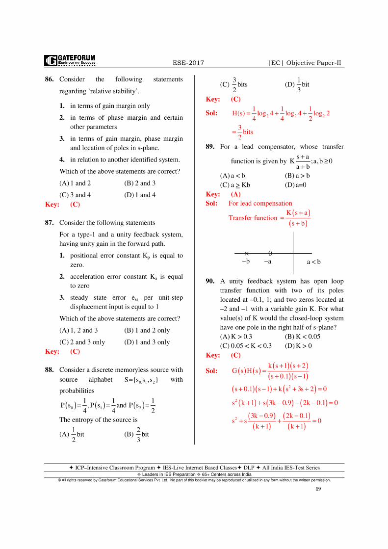
89. For a lead compensator, whose transfer
function is given by s a
K ;a,b 0a b
+≥
+
(A) a < b (B) a > b
(C) a > Kb (D) a=0
Key: (A)
Sol: For lead compensation
Transfer function ( )
( )K s a
s b
+=
+
90. A unity feedback system has open loop
transfer function with two of its poles
located at –0.1, 1; and two zeros located at
–2 and –1 with a variable gain K. For what
value(s) of K would the closed-loop system
have one pole in the right half of s-plane?
(A) K > 0.3 (B) K < 0.05
(C) 0.05 < K < 0.3 (D) K > 0
Key: (C)
Sol: ( ) ( ) ( )( )( )( )
( )( ) ( )2
k s 1 s 2G s H s
s 0.1 s 1
s 0.1 s 1 k s 3s 2 0
+ +=
+ −
+ − + + + =
( ) ( ) ( )2s k 1 s 3k 0.9 2k 0.1 0+ + − + − =
( )
( )( )
( )2
3k 0.9 2k 0.1s s 0
k 1 k 1
− −+ + =
+ +
b−× 0
a− a b<
ESE-2017 |EC| Objective Paper-II
ICP–Intensive Classroom Program IES-Live Internet Based Classes DLP All India IES-Test Series Leaders in IES Preparation 65+ Centers across India
© All rights reserved by Gateforum Educational Services Pvt. Ltd. No part of this booklet may be reproduced or utilized in any form without the written permission.
20
3k 0.9 0 2k 0.1 0
k 0.3 k 0.05
0.05 k 0.3
− < − >
< >
∴ < <
91. Consider that in a system loop transfer
function, addition of a pole result in the
following
1. Roots locus gets pulled to the right
hand side.
2. Steady-state error is increased.
3. Systems response gets slower.
Which of the above are correct?
(A) 1, 2 and 3 (B) 1 and 2 only
(C) 1 and 3 only (D) 2 and 3 only
Key: (C)
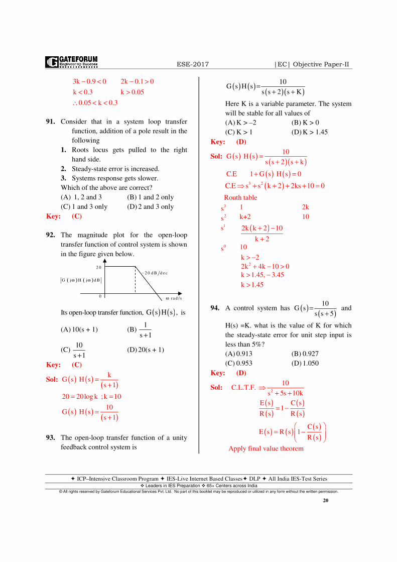
92. The magnitude plot for the open-loop
transfer function of control system is shown
in the figure given below.
Its open-loop transfer function, ( ) ( )G s H s , is
(A) 10(s + 1) (B) 1
s 1+
(C) 10
s 1+ (D) 20(s + 1)
Key: (C)
Sol: ( ) ( )( )
( ) ( )( )
kG s H s
s 1
20 20log k ;k 10
10G s H s
s 1
=+
= =
=+
93. The open-loop transfer function of a unity
feedback control system is
( ) ( )( )( )
10G s H s
s s 2 s K=
+ +
Here K is a variable parameter. The system
will be stable for all values of
(A) K > –2 (B) K > 0
(C) K > 1 (D) K > 1.45
Key: (D)
Sol: ( ) ( )( )( )
( ) ( )
10G s H s
s s 2 s k
C.E 1 G s H s 0
=+ +
+ =
( )3 2C.E s s k 2 2ks 10 0⇒ + + + + =
Routh table 3
s 1 2k 2
s k+2 10 1s ( )2k k 2 10
k 2
+ −
+
0s 10
k 2> −
22k 4k 10 0+ − >
k 1.45, 3.45> −
k 1.45>
94. A control system has ( )( )
10G s
s s 5=
+ and
H(s) =K. what is the value of K for which
the steady-state error for unit step input is
less than 5%?
(A) 0.913 (B) 0.927
(C) 0.953 (D) 1.050
Key: (D)
Sol: C.L.T.F.
( )( )
( )( )
( ) ( ) ( )( )
2
10
s 5s 10k
E s C s1
R s R s
C sE s R s 1
R s
⇒+ +
= −
= −
Apply final value theorem
( ) ( )G j H j d Bω ω
2 0
0
2 0 d B d e c−
ra d /sω
ESE-2017 |EC| Objective Paper-II
ICP–Intensive Classroom Program IES-Live Internet Based Classes DLP All India IES-Test Series Leaders in IES Preparation 65+ Centers across India
© All rights reserved by Gateforum Educational Services Pvt. Ltd. No part of this booklet may be reproduced or utilized in any form without the written permission.
21
( )
( )
( )
2
2s 0
101E s 1s s 5s 10k
101E s lims 1s s 5s 10k
1E s 1
k
→
= − + +
= × − + +
= −
ss sse 5% e 0.05
11 0.05k
k 1.05
< <
− <
<
95. What is the time required to reach 2% of
steady-state value, for the closed-loop
transfer function
( )( )
2,
s 10 s 100+ + when the input is u(t) ?
(A) 20 s (B) 2 s
(C) 0.2 s (D) 0.02s
Key: (C)
Sol: ( )( ) ( )( )
C s 2
R s s 10 s 100=
+ +
z 0.1sec=
s
2% error t 42 0.4 sec± = =
96. If the characteristics equation of a closed-
loop system is 22s 6s 6 0,+ + = then the
system is
(A) Over damped
(B) critically damped
(C) under damped
(D) undamped
Key: (C)
Sol: 2
2
n
n
2s 6s 6 0
s 3s 3 0
3rad / sec
2 3
+ + =
+ + =
ω =
ξω =
1ξ =< under damped system.
97. For derivative control action, the actuating
signals consists of proportional error signal
with addition of
(A) derivation of the error signals
(B) integral of the error signals
(C) steady-state error
(D) a constant which is a function of the
system type
Key: (A)
Sol: Controller output ( )p
dk e(t) e t
dt= +
Controller output is proportional error signal
with addition of rate of change of the error
signal.
98. Consider the following statements
regarding a PID controller
1. The error is multiplied by a negative
(for reverse action) proportional
constant P, and added to the current
output.
2. The error is integrated (averaged) over
a period of time and then divided by a
constant I, and added to the current
control output.
3. The rate of change of the error is
calculated with respect to time,
multiplied by another constant D, and
added to the output.
Which of the above statements are correct?
(A) 1, 2 and 3 (B) 1 and 3 only
(C) 1 and 2 only (D) 2 and 3 only
Key: (A)
100−× ×
10−
100 insignificant pole
10 dominant pole
− →
− →

ESE-2017 |EC| Objective Paper-II
ICP–Intensive Classroom Program IES-Live Internet Based Classes DLP All India IES-Test Series Leaders in IES Preparation 65+ Centers across India
© All rights reserved by Gateforum Educational Services Pvt. Ltd. No part of this booklet may be reproduced or utilized in any form without the written permission.
22
99. A 32kB RAM is formed by 16 numbers of
a particular type of SRAM IC. If each IC
needs 14 address bits, what is the IC
capacity?
(A) 32k bits (B) 16 k bits
(C) 8 k bits (D) 4k bits
Key: (B)
Sol: Total capacity
32kB 32k 8 bits 256 kbits= = × =
Since 16 IC’s are used, each IC provides
256 kbits/16=16kbits
Hence, capacity of each IC is 16 kbits.
Since, 14 bits address gives 16 kilo
locations; each chip has 16 kilo
locations. Hence, the IC organization is
16k 1× i.e., capacity of each IC is 16
kbits.
100. A cache line has 128 bytes. The main
memory has latency 64 ns and band-
width 1GB/s. the time required to fetch
the entire cache line is
(A) 32ns (B) 64ns
(C) 96ns (D) 192ns
Key: (D)
Sol: Given bandwidth = 14 bps
Latency = 64 ns
A cache lines has 128 bytes.
As per given bandwidth, 9
7 7 7
9
10 bytes 1sec
12 Bytes 2 2 ns
10
⇒
⇒ × =
Latency is given 64 ns
Therefore total time required to place
cache line is latency + data transfer time
64 ns 128 ns 192 ns⇒ + =
101. An asynchronous link between two
computers uses the start-stop scheme with
one start bit and one stop bit, and
transmission rate of 48.8 kbits/s. what is the
effective transmission rate as seen by the
two computers ?
(A) 480 bytes/s (B) 488 bytes/s
(C) 4880 bytes/s (D) 4800 bytes/s
Key: (C)
Sol: A serial asynchronous link contains start
and stop bits along with data bits of 8. So,
as per question, one start bit is given and
one stop bit is given. So
Total number of bits = 1 start bit + 1
stop bit + 8 data bits = 10 bits.
Efficiency
( )
( )
Number of data bit sent
Total number of bits
880% or 0.8
10
η =
= =
Given Transmission rate (Bandwidth)
= 48.8 kbits/sec
As we know that, effective transmission
rate is also called as throughput.
T
B
WhereT Throughput,B Bandwidth
η =
= =
Throughput B 0.8 48.8kbps⇒ = η× = ×
3848.8 10 Bps
10
48.8 10Bps
10
488100 Bps
10
= × ×
×=
×
4880 bps= ⇒ Hence option (C) is correct.
102. The noise factor of an attenuator pas that
has an insertion loss of 6dB is
(A) 0.25 (B) 0.5 (C) 2 (D) 4
Key: (D)
⇒
∴
∴
1 start bit 8 data bits 1 stop bit

ESE-2017 |EC| Objective Paper-II
ICP–Intensive Classroom Program IES-Live Internet Based Classes DLP All India IES-Test Series Leaders in IES Preparation 65+ Centers across India
© All rights reserved by Gateforum Educational Services Pvt. Ltd. No part of this booklet may be reproduced or utilized in any form without the written permission.
23
Sol: ( )( )
i
o
SN
Noise factor (F)S
N
=
103. A weighted complete graph with n vertices
has weights 2 i j− at edges ( )i j,ν ν . The
weight of a minimum spanning tree is.
(A) 2n
2 (B)
n
2
(C) 2n –2 (D) n –1
Key: (C)
Sol: ( )( )
2 2 2 .... 2 n 1 edges
2 n 1
2n 2
+ + + + −
= −
= −
104. Consider the following statements
regarding the functions if an operating
systems in a computer.
1. It controls hardware access
2. It manages files and folders.
3. It provides a user interface
4. It manages a user application.
Which of the above statements are correct?
(A) 1, 2 and 3only (B) 1,2 and 4 only
(C) 3 and 4 only (D) 1, 2, 3 and 4
Key: (D)
Sol: Statement 1 is “correct” because OS is a
control program which manages computer
hardware.
Statement 2 is “correct” because OS is also
called as resource manager.
Statement 3 and 4 are “correct” because OS
is an interface between user and hardware
of the computer.
Hence, all the given 4 statements are
“correct”. So option D
105. Consider the following processes which
arrived in the order 1 2 3P ,P and P
Process Burst time
1P 24 ms
2P 3 ms
3P 3 ms
What is the average waiting time by FCFS
scheduling?
(A) 17 ms (B) 19ms
(C) 21 ms (D) 23 ms
Key: (A)
Sol: Given snapshot and FCFS scheduling is
used.
PID AT BT
(in ms)
CTAT WT
0 24 2
24 0
0 3 2
27 24
0 3 3
30 27
Gantt chart
Therefore average waiting time
0 24 27 51
17 ms.3 3
+ += = =
106. The cumulative distributions function of a
random variable x is the probability that X
takes the value
(A) less than or equal to x
(B) equal to x
(C) greater than x
(D) zero
Key: (A)
Sol: Probability, R.V and R.P
( ) XF x P X x .
CDF
↑
= ≤
1P
2P
3P
0 24 27 301 2 3P P P

ESE-2017 |EC| Objective Paper-II
ICP–Intensive Classroom Program IES-Live Internet Based Classes DLP All India IES-Test Series Leaders in IES Preparation 65+ Centers across India
© All rights reserved by Gateforum Educational Services Pvt. Ltd. No part of this booklet may be reproduced or utilized in any form without the written permission.
24
107. A disk unit has 24 recording surface. It has
a total of 14000 cylinders. There is an
average of 400 sectors per track. Each
sector contains 512 bytes of data. What is
the data transfer rate at a rotational speed of
7200 r.p.m?
(A) 668.80 10 bytes s×
(B) 624.58 10 bytes s×
(C) 368.80 10 bytes s×
(D) 324.58 10 bytes s×
Key: (B)
Sol: Number of sectors / track = 400
As per question, 1 sector ⇒ 512 bytes
So that, size of the track
400 sectors 400 512 Bytes⇒ ⇒ ×
Rotational speed = 7200 rpm
6
60 sec 7200 rotations
72001 sec 120 rotations
60
11 rotation sec 400 512 bytes
120
1 sec 120 400 512 bytes
24.58 10 bytes / sec
⇒ →
⇒ =
⇒ ⇒ ⇒ ×
⇒ = × ×
= ×
108. In the demand paging memory, a page
table is held in registers. If it takes
1000ms to service a page fault and if the
memory access times is 10ms, what is
the effective access time for a page fault
rate of 0.01 ?
(A) 19.9 ms (B) 10.9 ms
(C) 9.99 ms (D) 0.99 ms
Key: (A)
Sol: In demand paging,
( )EAT P *S 1 P * m= + −
Where
P = Page fault rate
S = Page fault service time
M = Memory access time
As per question,
S = 1000 ms
M = 10 ms
P = 0.01
Therefore Effective Access Time (EAT)
( )( ) ( )( )0.01 1000 1 0.01 10
10 9.9 19.9 ms
= + −
= + =
Hence option A.
109. Consider the following statements
regarding database normal forms
1. Any relation with two attributes is
BCNF
2. Lossless, dependency - preserving
decomposition into BCNF is always
possible.
3. Lossless, dependency - preserving
decomposition into 3NF is always
possible.
4. BCNF is stricter than 3NF.
Which of the above statements are correct?
(A) 1, 2 and 3 (B) 1, 3 and 4
(C) 1, 2 and 4 (D) 2, 3 and 4
Key: (B)
Sol: 1. Every relation with two attributes
will be in BCNF. Because, if the
relation has two attributes the
possible sets are as follows.
DF
A B→
R AB
BCNF
I.
B A→
BCNF
II. R AB
ESE-2017 |EC| Objective Paper-II
ICP–Intensive Classroom Program IES-Live Internet Based Classes DLP All India IES-Test Series Leaders in IES Preparation 65+ Centers across India
© All rights reserved by Gateforum Educational Services Pvt. Ltd. No part of this booklet may be reproduced or utilized in any form without the written permission.
25
2&3.Lossless and dependency
preserving decomposition into 3 NF is
always possible but lossless and
dependency preserving BCNF may not
be always possible [lossless
decomposition into BCNF is always
possible but dependency preserving
BCNF may not always be possible].
4. BCNF is stricter than 3 NF because a
table is in BCNF if LHS of every FD is
super key. If this condition is satisfied
there will not be any partial and
transitive dependency table will be
in 3 NF for sure. But if a table is in 3
NF it will not be knowing partial and
transitive dependencies but LHS of
every FD need not be super key table
need not be in BCNF.
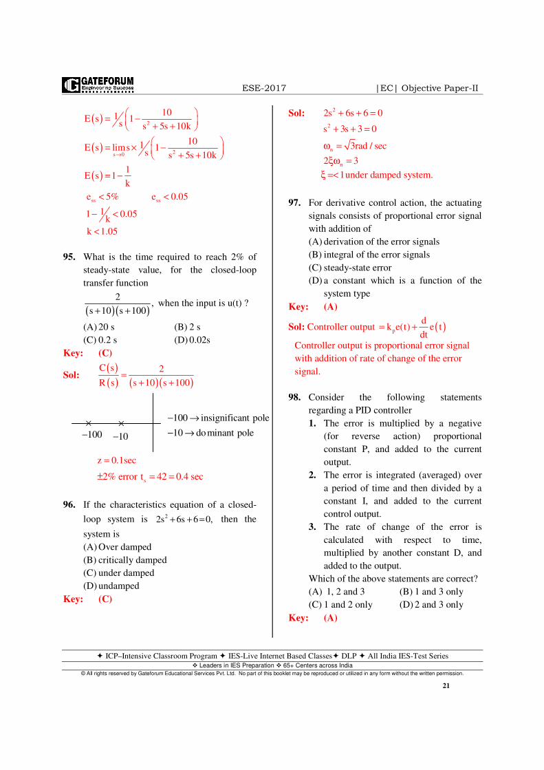
110. Consider the following schedules for
transactions T1, T2 and T3
T1 T2 T3
Read (X)
Read (Y)
Read (Y)
Write (Y)
Write (X)
Write (X)
Read (X)
Write (X)
The correct schedule of serialization will be
(A) 1 2 3T T T→ → (B)
2 3 1T T T→ →
(C) 3 1 2
T T T→ → (D) 1 3 2
T T T→ →
Key: (D)
Sol:
1 3 2T T T⇒ → →
111. A receiver tunes signals from 550 kHz to
1600kHz with an IF of 455 kHz. The
frequency tuning range ratio for the
oscillator section of the receiver is nearly
(A) 2.90 (B) 2.05
(C) 1.65 (D) 1.30
Key: (B)
Sol: Frequency tuning range ratio
1600 455 2055
2.047 2.05550 455 1005
+= = = ≈
+
112. In a basic transmission line the voltage at
the receiving end without load is 660V; and
it is 420V with full load. What is the
percentage of voltage regulation?
(A) 77% (B) 67%
(C) 57% (D) 47%
Key: (C)
Sol: NL FL
FL
V VVoltage regulation 100
V
660 420100 57%
420
−= ×
−= × =
113. A quarter - wave transformer of
characteristics impedance 60Ω has been
used to match a transmission line of 72Ω .
What is the characteristic impedance of the
⇒
⇒
2T
3T
1T
R AB
A B→B A→
BCNF
III.
R ABIV.
ESE-2017 |EC| Objective Paper-II
ICP–Intensive Classroom Program IES-Live Internet Based Classes DLP All India IES-Test Series Leaders in IES Preparation 65+ Centers across India
© All rights reserved by Gateforum Educational Services Pvt. Ltd. No part of this booklet may be reproduced or utilized in any form without the written permission.
26
transformer, when the load of 72Ω is
replaces by98Ω ?
(A) 98Ω (B) 80Ω
(C) 70Ω (D) 60Ω
Key: (C)
Sol: 2
0in
L
0
Z 60Z 50
Z 72
Z 50 98
70
= = = Ω
= ×
= Ω
114. Consider the following statements
Stokes’ theorem is valid irrespective of
1. Shape of closed curve C
2. type of vector A
3. type of coordinate system
4. whether the surface is closed or open.
Which of the above statements are correct?
(A) 1, 2 and 4 (B) 1, 3 and 4
(C) 2, 3 and 4 (D) 1, 2 and 3
Key: (D)
Sol: C S
Strokes theorem : F.d F.ds
open Surface
= ∇ ×∫ ∫∫
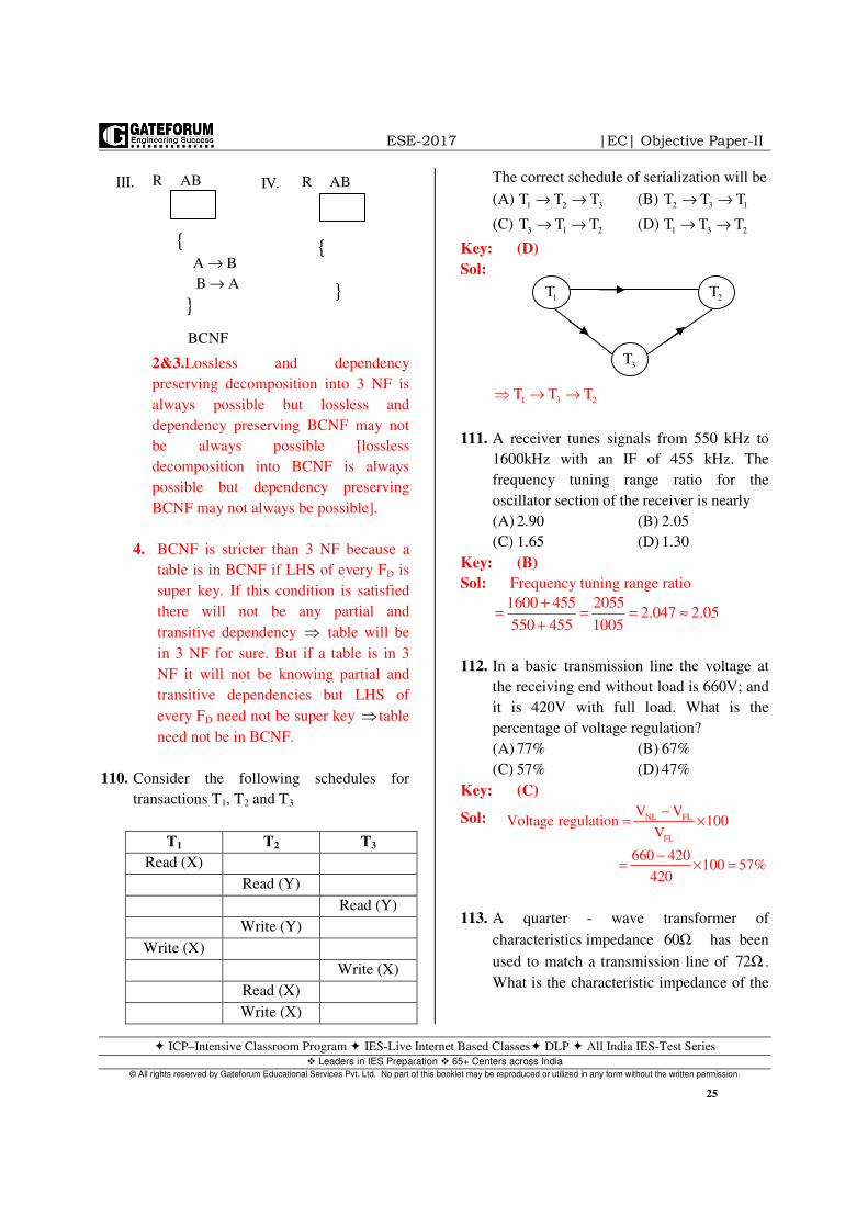
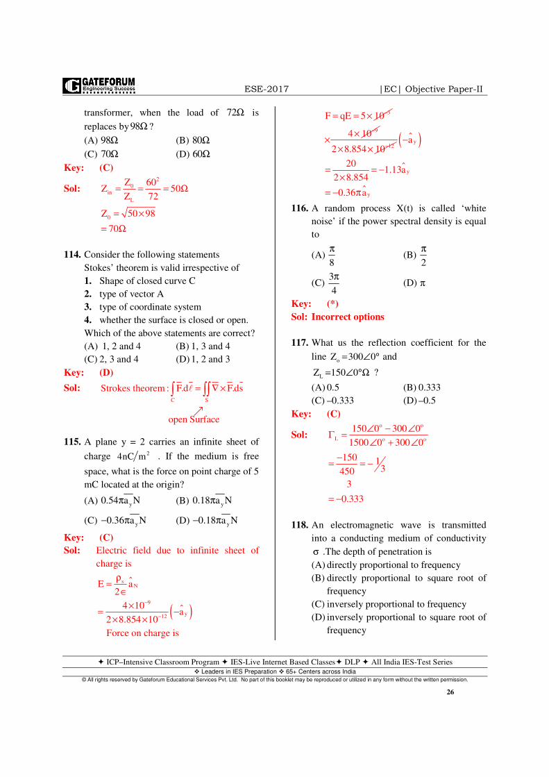
115. A plane y = 2 carries an infinite sheet of
charge 24nC m . If the medium is free
space, what is the force on point charge of 5
mC located at the origin?
(A) y0.54 a Nπ (B) y
0.18 a Nπ
(C) y0.36 a N− π (D) y0.18 a N− π
Key: (C)
Sol: Electric field due to infinite sheet of
charge is
( )
sN
9
y12
E a2
4 10a
2 8.854 10
−
−
ρ=
∈×
= −× ×
Force on charge is
3F qE 5 10−= = ×94 10−×
×122 8.854 10−× ×
( )y
y
y
a
201.13a
2 8.854
0.36 a
−
= = −×
= − π
116. A random process X(t) is called ‘white
noise’ if the power spectral density is equal
to
(A) 8
π (B)
2
π
(C) 3
4
π (D) π
Key: (*)
Sol: Incorrect options
117. What us the reflection coefficient for the
line o
Z 300 0= ∠ ° and
L
Z 150 0= ∠ °Ω ?
(A) 0.5 (B) 0.333
(C) –0.333 (D) –0.5
Key: (C)
Sol: o o
L o o
150 0 300 0
1500 0 300 0
150 13450
3
0.333
∠ − ∠Γ =
∠ + ∠
−= = −
= −
118. An electromagnetic wave is transmitted
into a conducting medium of conductivity
σ .The depth of penetration is
(A) directly proportional to frequency
(B) directly proportional to square root of
frequency
(C) inversely proportional to frequency
(D) inversely proportional to square root of
frequency

ESE-2017 |EC| Objective Paper-II
ICP–Intensive Classroom Program IES-Live Internet Based Classes DLP All India IES-Test Series Leaders in IES Preparation 65+ Centers across India
© All rights reserved by Gateforum Educational Services Pvt. Ltd. No part of this booklet may be reproduced or utilized in any form without the written permission.
27
Key: (D)
Sol: skin depth 2 1
;f
δ = δ αωµσ
119. Which of the following are the properties of
TEM mode in a lossless medium?
1. Its cut-off frequency is zero.
2. Its transmission line is a hallow
waveguide.
3. Its wave impedance is the impedance in
a bounded dielectric
4. Its phase velocity is the velocity of light
in an unbounded dielectric.
Select the correct answer using the code
given below.
(A) 1, 2 and 3 (B) 1, 3 and 4
(C) 1, 2 and 4 (D) 2, 3 and 4
Key: (C)
Sol: TEM 0
120η = η = πΩ
Statements given are are the properties
of TEM wave.
120. Consider the following statements
Plane wave propagation through a circular
waveguide result in
1. TE modes
2. TM modes
Which of the above statements is/are
correct?
(A) 1 only (B) 2 only
(C) Either 1 or 2 (D) Both 1 and 2
Key: (D)
121. In VLSI n- MOS process, the thinox mask
(A) patterns the ion implantation within the
thinox region
(B) deposits polysilicon all over the thikox
region
(C) patterns thickox regions to expose
silicon where source, drain or gate areas
are required
(D) grows thickox over thinox regions in
gate areas
Key: (A)
Sol: Property of end fire array.
122. For a random variable x having the PDF
shown in the figure given below.
The mean and the variance are respectively
(A) 0.5 and 0.66 (B) 2.0 and 1.33
(C) 1.0 and 0.66 (D) 1.0 and 1.33
Key: (D)
Sol: Probability, R.V and R.P
a b 1 3
mean 12 2
+ − += = =
( ) ( )( )223 1b a
variance12 12
164 3 1.33
12
− −−= =
= = =
123. Consider the statements with respect to
bilinear transformation method of digital
design
1. It preserves the number of poles and
there by the order of the filter.
2. It maintains the phase response of
analog filter
3. The impulse response of the analog
filter is not preserved.
Which of the above statements are correct?
(A) 1, 2 and 3 (B) 1 and 2 only
(C) 1 and 3 only (D) 2 and 3 only
Key: (C)
( )xP x
1 0 1 2 3− x

ESE-2017 |EC| Objective Paper-II
ICP–Intensive Classroom Program IES-Live Internet Based Classes DLP All India IES-Test Series Leaders in IES Preparation 65+ Centers across India
© All rights reserved by Gateforum Educational Services Pvt. Ltd. No part of this booklet may be reproduced or utilized in any form without the written permission.
28
Sol: Bilinear transform does not maintain the
phase characteristics of the Analog Filter
& there is no way to correct the phase
response to match.
124. Consider the following statements
The 8259A programmable interrupt
controller can
1. manage eight interrupts
2. vector an interrupt request anywhere in
the memory map.
3. have 8-bit and 16-bit interval between
interrupt vector locations
4. be initialized with operational
command words.
Which of the above statements are correct?
(A) 1, 2 and 3 only (B) 1, 2 and 4 only
(C) 3 and 4 only (D) 1, 2, 3 and 4
Key: (B)
125. What are the conditions which are
necessary for using a parallel port?
1. Initializing by placing appropriate bits
at the control register.
2. Calling on interrupt whenever a status
flag sets at the status register.
3. Interrupting servicing (device driver)
programming
Select the correct answer using the code
given below.
(A) 1, 2 only (B) 1 and 3 only
(C) 1, 2 and 3 (D) 2 and 3 only
Key: (B)
126. Consider a point-to-point
communication network represented by
a graph. In terms of graph parameters,
the maximum delay (quality of service)
experienced by a packet employing
Bellman-Ford routing algorithm is/are
1. diameter of the graph
2. Shortest path on the graph
3. sum of all edges weights in the graph
Select the correct answer using the code
given below.
(A) 1 only (B) 2 only
(C) 3 only (D) 1, 2 and 3
Key: (B)
Sol: Basically, Routing Algorithms are used
to find the shortest path between any 2
nodes. As per question, it is given
Bellman-Ford routing algorithm
(Distance vector routing algorithm) is
used to find shortest path on the graph.
Hence, option (B) is correct.
127. Lets RSA prime number be p = 3 and
q = 11. If the corresponding public key e =
3, what is the private key?
(A) 4 (B) 5 (C) 6 (D) 7
Key: (D)
Sol: Given: p = 3 q =11 e = 3 d = ?
As per RSA algorithm,
Step 1: Chosen p 3 and q 11= =
Step 2: Compute n p q 3 11 33= × = × =
Step 3: Compute
( ) ( )( ) ( )( )n p 1 q 1 2 10 20φ = − − = =
Step 4: Given e = 3, so compute a value
for d such that
( )d .e. mod n 1⇒ φ =
d .3 mod 20 1
d 7
⇒ =
⇒ =
128. The maximum radiation for an endfire array
occurs at
(A) 0
0φ = (B) 02
πφ =
(C) 02
πφ = − (D) 0
3
2
πφ =
Key: (A)
Sol: The radiation pattern of end fire array

ESE-2017 |EC| Objective Paper-II
ICP–Intensive Classroom Program IES-Live Internet Based Classes DLP All India IES-Test Series Leaders in IES Preparation 65+ Centers across India
© All rights reserved by Gateforum Educational Services Pvt. Ltd. No part of this booklet may be reproduced or utilized in any form without the written permission.
29
The minimum radiation occur at o
o0φ =
129. Consider the following statements
regarding TCP:
1. It enables two hosts to establish
connections and exchange streams of
data.
2. It guarantees delivery of data in the
same order in which they are sent
3. TCP segmentation offload is used to
reduce the CPU overhead of TCP/IP on
fast networks
Which of the above statements are correct?
(A) 1 and 2 only (B) 1 and 3 only
(C) 2 and 3 only (D) 1, 2 and 3
Key: (D)
Sol: Statement 1 is “correct” because
TCP is a connection oriented
protocol.
Statement 2 is “correct” because TCP
provides reliable delivery
Statement 3 is “correct” because
TCP segment offload (TSO) breaks
down large groups of data sent over a
network into smaller segments that pass
through all the network elements
between the source and destination. This
type of off load relies on the NIC to
segment the data and then add the TCP,
IP and DLL protocol headers to each
segment. TSO is also called as LSO
“large segment offload”.
130. The transmission path loss for a
geostationary satellite signal for uplink
frequency of 6GHz is
(A) 60dB (B)92 dB
(C) 184 dB (D) 200dB
Key: (D)
Sol: Path Loss
MHz km34.52 20lag f 20lag d= + +
MHz
km
f 6000MHz
d 36,000Km
=
=
10
Path Loss
34.52 20lag 6000 20log36,000
34.52 75.56 91.126
200dB
⇒
= + +
= + +
=
131. Consider the following statements
If the maximum range of radar has to be
doubled
1. The peak transmitted power may be
increased 16 folds
2. the antenna diameter may be doubled
3. the sensitivity of receiver may be
doubled
4. the transmitted pulse width may be
doubled
Which of the above statements are correct?
(A) 1and 2 (B) 2 and3
(C) 3 and 4 (D) 1 and 4
Key: (A)
Sol: Radar Range equation
( )
2 2
t4
3
min
P GR
4 P
λ σ=
π
For R to be doubled
t
P need to be16 times
G need to be 4 times
Area need to be inverse 4 times
diameter to be doubled.
132. What is the maximum signal propagation
time for a geosynchronous satellite
transmission system?
(A) 140ms (B) 220ms
(C) 280ms (D) 560 ms
Key: (C)
Sol: A geostationary satellite is visible from a
⇒

ESE-2017 |EC| Objective Paper-II
ICP–Intensive Classroom Program IES-Live Internet Based Classes DLP All India IES-Test Series Leaders in IES Preparation 65+ Centers across India
© All rights reserved by Gateforum Educational Services Pvt. Ltd. No part of this booklet may be reproduced or utilized in any form without the written permission.
30
little less than 1/3rd
of earth’s surface & if you
are located at the edge of this Area the satellite
appears to be just above the horizon. The
distance to satellite is greater & for earth stations
at the extreme edge of the coverage Area, the
distance to satellite is approx is 41756 km. If you
were to communicate with another similarly
located site, the total distance is nearly 84000
km, so the end to end delay is 280 msec.
133. The field strength at the receiving antenna
location at a distance of 28 km from a half-
wave dipole transmitter radiating 0.1kW is
(A) 1.5 mV/m (B) 2.5 mV/m
(C) 3.5 mV/m (D) 4.5m V/m
Key: (B)
Sol:
( )
rad
avg d 2
2
s
d avg
2 3s
23
3
s
PP G
4 r
EG 1.5 for half wave dipole.P
2
E 0.1 101.5
2 120 4 28 10
E 2.39 10 V/m.−
=π
= =η
×=
× π π ×
= ×
134. Consider the following loop
MOV CX, 8000h
L1: DEC CX
JNZ L1
The processor is running at 14.7456/3 MHz
and DEC CX requires 2 clock cycles and
JNZ requires 16 clock cycles. The total
time taken is nearly
(A) 0.01s (B) 0.12s (C) 3.66s (D) 4.19s
Key: (B)
Sol: Total time taken
6 33
10 18 8 1614.7456
0.12sec
−= × × × ×
=
135. A microwave communication link employs
two antennas for transmission and reception
elevated at 200m and 80m, respectively.
Considering obliqueness of the earth, the
maximum possible link distance is
(A) 46 km (B) 64 km
(C) 96 km (D) 102 km
Key: (C)
Sol: ( )( )( )
t rd 4.12 h h
4.12 200 80
4.12 14.14 9 96km
+
= +
= +
136. Consider a packet switched network based
on a virtual circuit mode of switching. The
delay jitter for the packets of a session from
the source node to the destination node
is/are
1. always zero
2. non-zero
3. for some networks, zero
Select the correct answer using the code
given below.
(A) 1 only (B) 2 only
(C) 3 only (D) 2 and 3
Key: (A)
Sol: In a packet switched network based on a
virtual circuit mode of switching the delay
jitter for the packets of a session from
source to destination node is always zero
because a packet can be forwarded before
the next packet arrives.
137. Molybdenum has Body-Centered cubic
(BCC) structure with an atomic radius of
1.36 o
A . Then the lattice parameter for
BCC molybdenum is
(A) 2.77 o
A (B) 3.14 o
A

ESE-2017 |EC| Objective Paper-II
ICP–Intensive Classroom Program IES-Live Internet Based Classes DLP All India IES-Test Series Leaders in IES Preparation 65+ Centers across India
© All rights reserved by Gateforum Educational Services Pvt. Ltd. No part of this booklet may be reproduced or utilized in any form without the written permission.
31
(C) 5.12 o
A (D) 6.28 o
A
Key: (B)
Sol:
0
4Ra
3
4 1.363.14A
3
=
×= =
Directions:
Each of the next thirteen (13) items consists of
two statements, one labeled as ‘statement (I)’
and the other as ‘statement (II)’. Examine these
two statements carefully and select the answer to
these items using the code given below.
Codes:
(A) Both statement (I) and statement (II) are
individually true and statement (II) is the
correct explanation of statement (I)
(B) Both statement (I) and statement (II) are
individually true but statement (II) is
not the correct explanations of
statements (I)
(C) Statement (I) is true but statement (II) is
false
(D) Statement (I) is false but statement (II)
is true
138. Statement (I): The coupling between two
magnetically coupled coils is said to be
ideal if the coefficient of coupling is unity.
Statement (II): Lower the self-inductance
of a coil, more will be the e.m.f induced
Key: (C)
Sol: Statement – I is true.
Statement – II: - We have, di
V L.dt
=
Where, L is self – inductance of a coil
and V is induced EMF (or) voltage.
As induced EMF and self – inductance
are directly proportional to each other.
Hence statement – II is wrong.
139. Statement (I): The direction of
dynamically induced e.m.f in a conductor is
determined by Fleming’s left-hand rule.
Statement (II): The mutual inductance
between two magnetically isolated coils is
zero.
Key: (B)
Sol: Both statements are true but statement II
is not reason for statement I
140. Statement (I): Photodiodes are not used in
relay circuits
Statement (II): The current needed to
activate photodiodes is very low even at
high light intensities.
Key: (D)
Sol: Photo diodes are commonly used in relay
circuits which we called photo relay
circuits.
141. Statement (I): An autotransformer is
economical in using copper in its manufacture.
Statement (II): The section of the winding
common to both primary and secondary
circuits carries only the different of primary
and secondary currents.
Key: (B)
142. Statement (I): FIR filters are always stable.
Statement (II):IIR filters require less
memory and are less complex.
Key: (B)
Sol: For a finite input, the output is also always
finite in FIR filters. Thus the system is stable.
For an FIR filter, H(z) contains only zeros
thus they need more memory. While the

ESE-2017 |EC| Objective Paper-II
ICP–Intensive Classroom Program IES-Live Internet Based Classes DLP All India IES-Test Series Leaders in IES Preparation 65+ Centers across India
© All rights reserved by Gateforum Educational Services Pvt. Ltd. No part of this booklet may be reproduced or utilized in any form without the written permission.
32
H(z) of IIR filters contain both zeros and
poles and it requires less memory.
143. Statement (I): Nuclear power plants are
suitable only for base load operation
Statement (II): Nuclear power reactor
cannot response to load fluctuation
efficiently
Key: (A)
144. Statement (I): Solar insolation is a
measure of solar irradiance over a specified
period of time
Statement (II): Solar insolation data are
commonly used for isolated PV system
design.
Key: (B)
145. Statement (I): The smallest change of
input detectable at the output is called the
resolution of a transducer.
Statement (II): A high resolution means
high accuracy.
Key: (B)
146. Statement (I): Constant M and N circles as
also Nichols charts are graphical techniques
to assess closed-loop performance in the
frequency domain.
Statement (II): While constant M and N
circles use Nyquist polar plots data Nichols
chart uses Bode plots data.
Key: (B)
147. Statement (I): PID controller is an essential
part of any control loop in process industry.
Statement (II): PID control system
performs better than most predictive control
methods in the context of measured
disturbances.
Key: (A)
148. Statement (I): Large RAM with MOS
circuit technology is used for the main
memory in a computer system.
Statement (II): An important application
of ROM is to store system programs,
library subroutines, etc.
Key: (B)
149. Statement (I): Elements with non-
minimum phase transfer functions
introduce large phase lags with increasing
frequency resulting in complex
compensation problems
Statement (II): Transportation lag
commonly encountered in process control
systems is a non-minimum phase element.
Key: (B)
150. Statement (I): Speech enhancement
techniques are used to make a processed
speed signal sound superior to the
unprocessed one.
Statement (II):A ‘Perfect signal’ is
required as reference for speech
enhancement.
Key: (C)
Sol: Speech Enhancement is done
Based on requirement not tuned on perfect
signal (which is not available).