1, k. kadirgama1, d. ramasamy1, m.a. maleque2 and m.m. noor1
TRANSCRIPT

International Journal of Automotive and Mechanical Engineering
ISSN: 2229-8649 (Print); ISSN: 2180-1606 (Online);
Volume 14, Issue 1 pp. 3913-3926 March 2017
©Universiti Malaysia Pahang Publishing
DOI: https://doi.org/10.15282/ijame.14.1.2017.8.0318
3913
Experimental investigation on the performance of the TiO2 and ZnO
hybrid nanocoolant in ethylene glycol mixture towards AA6061-T6 machining
N.S.M. Sahid1, M.M. Rahman1, K. Kadirgama1, D. Ramasamy1, M.A. Maleque2
and M.M. Noor1
1Faculty of Mechanical Engineering, Universiti Malaysia Pahang
26600 Pekan, Pahang, Malaysia
Email: [email protected]
Phone; +6094246239; Fax: +6094245444 2Department of Manufacturing and Materials Engineering
International Islamic University Malaysia
53100 Kuala Lumpur, MALAYSIA
ABSTRACT
This paper presents an experimental investigation on the coated carbide cutting tool
performance of aluminium alloy AA6061-T6 machining through end mill processes using
the minimum quantity lubrication (MQL) technique. The process parameters including
the cutting speed, depth of cut and feed rate are selected. The effect of the base fluid ratio
(water: EG) to the hybrid nanocoolant was investigated in this experiment. The hybrid
nanocoolant with 80:20 of volume concentration up to 0.1% was prepaid with a 21 nm
particle size of TiO2 and 10-30 nm ZnO nanoparticle for measurement purposes and tested
at cnc end milling machines. The analysis of the variance method is utilised to validate
the experimental data and to check for adequacy. The response surface method was used
to develop the mathematical models and to optimise the machining parameters. It is
observed that the material removal rate depends significantly on the depth of cut and feed
rate, followed by the spindle speed. The results can be used as an example of the minimum
quantity lubricants (MQL) technique applied to the machining of aluminium alloys,
providing economic advantages in terms of reduced the machining costs and better
machinability.
INTRODUCTION
Machinability is one of the most important properties of a material. It is about cutting the
material with maximum metal removal, shortest time, maximum tool life and a smooth
surface finish [1-6]. Nowadays, the demand in various applications for fluids with more
efficient heat transfer has led to enhance heat transfer to meet the cooling challenge
necessary, such as in the electronics, photonics, transportation and energy supply
industries. In the present study, the effect of different parameters on the surface finish of
the material is investigated using a CNC end milling machine [7-14]. The tool geometry
parameters play an important role in determining the overall machining performance,
including cutting forces, tool wear, surface finish, chip formation and chip breaking [15-
17]. The value of surface roughness increased linearly with the increase of the tool
diameter and spindle speed; the feed rate played an important role when other parameters
remained constant [18]. The principal wear mechanisms in aluminium alloys machining
are the burr formation, built-up-edge as well as surface roughness. The surface finish and

Experimental investigation on the performance of the TiO2 and ZnO hybrid nanocoolant in ethylene glycol mixture
towards AA6061-T6 machining
3914
burr formation in aluminium alloy machining are mainly used as tool life criteria as it is
difficult to observe tool wear in aluminium alloys [19-22].
The minimum quantity lubrication has been proved to be an effective near dry
machining technique as well as an efficient alternative to completely dry and wet cutting
conditions from the viewpoint of cost, ecological and human health issues and machining
process performance [23-28]. The purpose in sustainable machining is to produce the
parts using an optimised minimum quantity of metal working fluids so that the workpiece,
chips and environment remain dry after cutting. Besides environmental and health issues,
the costs associated with the applications, storage and disposal of cutting fluids are also a
concern. About 15-20 % of the overall machining costs are related to cooling and
lubricating fluids [29-32]. Most of the research studies involving machining with MQL,
as a cutting medium, have been mainly concerned with the turning, drilling and grinding
process. There have been very few articles published which use MQL in end milling [14,
29, 33-37]. The usual applied in the end milling process is the application of abundant
amounts of liquid coolant, whereby the liquid coolant as intermittent cooling increases
the temperature variations and build up edge. Hence, simply cutting off the amount of
coolant used is not a practical answer for end milling due to the intermittent nature of the
cutting action at the tool tip resulting in increased temperature variations at the tip of the
tool. Thus, the role of MQL as a potential method is still to be explored for minimising
the consequences of thermal shock in end milling for removing the generated heat during
the entire cutting cycle. End milling is one of the most widely used metal removal
operations in the industry because of its ability to remove material faster, giving a
reasonably good surface finish. Owing to the significant role that milling operations play
in today's manufacturing world, there is a vital need to optimise the machining parameters
for this operation, particularly when CNC machines are employed.
The objective of the present work is to study the effect of the hybrid nanocoolant
with 80:20 volume concentration of TiO2:ZnO towards the material removal rate, surface
roughness and tool wear using the end milling machine. The investigation on these
rheological properties is very important to expand the application of the hybrid
nanocoolant with addition of EG in the coolant of machining. The selection of ZnO and
TiO2 nanoparticles with a 21nm particle size and 10-30 nm ZnO are due to its stability
period that withstand up to two months. The purpose of this study is to optimise the
process of minimum quantity lubrication in the end milling of the aluminium alloy
AA6061T6.
METHODS AND MATERIALS
Hybrid Nanocoolant Preparation
The hybrid nanocoolant used in the sample preparation is 21 nm in particle size of TiO2
and 10-30 nm ZnO in powder form, respectively. The nanoparticles were suspended in
80:20 TiO2:ZnO by volume percent. Figure 1 shows the process flow of the preparation
of the hybrid nanocoolant. A two-step method was used in the preparation of the hybrid
nanofluid. The sonication process was employed to help improve the dispersion of
nanoparticles in the base fluid. The nanoparticles are dispersed in the base fluid using a
magnetic stirrer and sonicated in an ultrasonic bath for two hours [38-40]. The samples
prepared for a ratio of 80:20 of TiO2 and ZnO have been found to be stable for two
months. Equation (1) was used to determine the mass of ZnO and TiO2 to disperse in the
base fluid.

Sahid et al. / International Journal of Automotive and Mechanical Engineering 14(1) 2017 3913-3926
3915
mixture
ZnO
ZnO
Tio
Tio
ZnO
ZnO
Tio
Tio
Vmm
mm
2
2
2
2
(1)
Viscosity Measurement
The viscosity was measured with a Brookfield LVDV III Ultra Rheometer. The range of
applicability of the measurement is from 1 to 6 × 10⁶ mPa.s. Figure 2 shows the setup of
the experiment for measuring the viscosity. The rheometer is used to make accurate and
reproducible measurements on low viscosity materials. A hybrid nanocoolant with a 16
ml volume sample was inserted into a cylinder jacket and attached to the rheometer. A
RheoCal program was installed for the data measurement at the designated torque and
temperature. The sample was heated from 50 to 70 °C for the viscosity measurement. To
validate the data, the reading of the torque from the measurement was selected within the
range of 10-100%.
Figure 1. Process flow in the preparation of the hybrid nanocoolant.
Thermal Conductivity
The thermal conductivity of nanofluids is one of the reasons for the enhancement of heat
transfer. The large (100 mm long, 2.4 mm diameter) single needle TR-1 sensor from
KD2Pro measures the thermal conductivity and the thermal resistivity has been used. For
the dual-needle sensor, the needles must remain parallel to each other during insertion to
make an accurate reading. Because the sensors give off a heat pulse it is necessary to
Measuring the hybrid
nanocoolant
Stirring the hybrid nanocoolant
Sample hybrid nanocoolant Immersed in an ultrasonic
bath for 2 hours

Experimental investigation on the performance of the TiO2 and ZnO hybrid nanocoolant in ethylene glycol mixture
towards AA6061-T6 machining
3916
allow a minimum of 1.5 cm of material parallel to the sensor in all directions, or errors
will occur. When the temperature of the sample is different from the temperature of the
needle, the needle must equilibrate to the surrounding temperature before beginning a
reading. Thus, the calibration process has also been used with a standard fluid (Glycerin),
which was already brought with devices. Validating the data error of the reading from the
measurement was less than 0.01.
Figure 2. Viscosity measurement with the Brookfield Rheometer.
Experimental Details
The machining parameters selected in this research are the spindle speed, feed rate, depth
of cut and the minimum quantity lubricant flow rate to investigate the material removal
rate, surface roughness and tool wear. The central composite design approach of the
response surface methodology is used for the design of experiments in order to find the
effects and the combination of the parameters. The flow rates for the MQL used are 36
ml/hour, 72 ml/hour and 144 ml/hour. The MQL coolants used a hybrid nanofluid with a
0.1 concentration. Table 1 shows the chemical composition of the workpiece used for the
experiment which is aluminium alloys A6061. Table 2 shows the design of the experiment
matrix for this study. Three levels of machining variables are selected.
Table 1. Chemical composition of the Aluminium Alloy A6061.
The surface roughness and material removal rate are the two conflicting responses
of the experiments. The surface roughness is measured using a perthometer (MarSurf XR
20 (Mahr)) while the material removal rate is calculated by weighing the workpiece after
every single cut. The surface roughness (Ra) is measured in μm. The tool wear is
Component Amount (%wt)
Aluminium Balance
Magnesium 0.8-1.2
Silicon 0.4-0.8
Iron Maz 0.7
Copper 0.15-0.40
Zinc Max 0.25
Titanium Maz 0.15
Manganese 0.04-0.35
Others 0.05
Rheometer
Spindle
Sample
jacket Sample
Hybrid nano

Sahid et al. / International Journal of Automotive and Mechanical Engineering 14(1) 2017 3913-3926
3917
measured in µm with a FESEM. The specimen workpiece material used is an AA6061T6
aluminium alloy with wide-ranging applications in the industry on account of its good
machinability and continuous chips. The workpiece has the dimension of 100 mm × 100
mm × 20 mm. The density of the alloy used for calculating the material removal rate is
0.0027g/mm3. A coated tungsten carbide end mill with two flutes is selected for the
machining. An analysis of variance (ANOVA) is utilised to verify the adequacy of the
experimental data. A commercial non-toxic type of renewable vegetable oil-based cutting
fluid (Coolube 2210, UNIST, Inc.) is used. Experiments are performed using a vertical
CNC milling centre, the HAAS VF6.
Table 2. Design of experiments.
Factors Levels
1 2 3
Spindle speed (rev/min) 3000 4800 6800
Federate (mm3/min) 610 975 1382
Depth of cut (mm) 0.35 0.95 1.3
RESULTS AND DISCUSSION
The optimal cutting parameters were obtained using the objectives as to minimise the
surface roughness and simultaneously maximise the material removal rate, within the
specified limits of the parameters as maximum and minimum boundary conditions for
optimisation. A response surface is developed to predict the surface roughness (Ra) and
material removal rate (mm3/min) and the set of cutting parameters is selected for a given
range of material removal rate until the tool wear reaches 0.3 μm, by which the surface
roughness is not affected. The significance of the input parameters is determined based
on the difference in the mean of the two groups of experimental design at high and low
levels. The relative importance and rankings of the main parameters and their interactions
with respect to response variables are evaluated by determining the parameters effect size
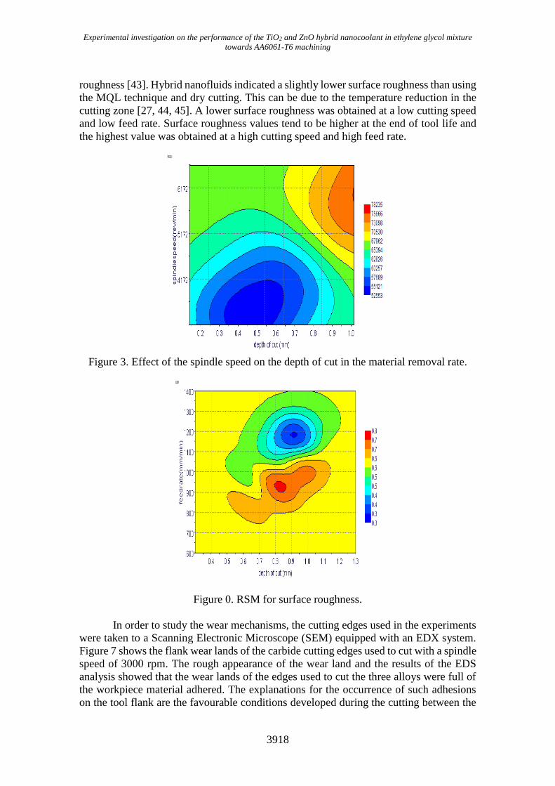
using RSM. Figure 3 presents the effect of the spindle speed on the depth of cut in the
material removal rate. Figure 3 shows the optimum result for surface roughness when the
speed is 5718 rev/min and the feed rate is 1047 mm3/min. Figure 4 shows the optimum
result for the material removal rate. It shows that the best speed is 5124 rev/min and the
feed rate is 600 mm3/min and the material removal rate is 67597 mm/min.
One of the typical techniques to accurately quantify surface integrity is the surface
finish measurement. It is considered as an indicator for the surface quality of the turned
part, reporting that the wiper geometry provides the ability to duplicate the feed value and
achieve the same surface finish with a conventional tool. It is suggested that the surface
roughness values in finish machining are expected to be in the range of 0.5- 1.5 µm [41].
Figures 5-6 show the comparison between dry, MQL and hybrid nanofluids in terms of
surface roughness and material removal rate at different cutting speed, depth of cut and
feed rate values. Hybrid nanofluids show a slight improvement in enhancing surface
roughness compared to the dry and MQL technique due to the lesser effect of the cooling
function of the cutting fluid, which is significantly effective as a lubricant more than its
function as a coolant [20]. The surface roughness value is increasing at a high speed and
feed for dry and lubricated surfaces and the improvement in surface roughness can be
attributed to the reduction in the material transfer onto the machined surface [42].
However, applying the MQL was also reported to result in some improvement in surface
Experimental investigation on the performance of the TiO2 and ZnO hybrid nanocoolant in ethylene glycol mixture
towards AA6061-T6 machining
3918
roughness [43]. Hybrid nanofluids indicated a slightly lower surface roughness than using
the MQL technique and dry cutting. This can be due to the temperature reduction in the
cutting zone [27, 44, 45]. A lower surface roughness was obtained at a low cutting speed
and low feed rate. Surface roughness values tend to be higher at the end of tool life and
the highest value was obtained at a high cutting speed and high feed rate.
Figure 3. Effect of the spindle speed on the depth of cut in the material removal rate.
Figure 0. RSM for surface roughness.
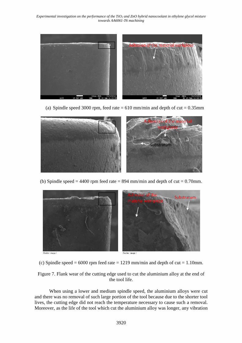
In order to study the wear mechanisms, the cutting edges used in the experiments
were taken to a Scanning Electronic Microscope (SEM) equipped with an EDX system.
Figure 7 shows the flank wear lands of the carbide cutting edges used to cut with a spindle
speed of 3000 rpm. The rough appearance of the wear land and the results of the EDS
analysis showed that the wear lands of the edges used to cut the three alloys were full of
the workpiece material adhered. The explanations for the occurrence of such adhesions
on the tool flank are the favourable conditions developed during the cutting between the

Sahid et al. / International Journal of Automotive and Mechanical Engineering 14(1) 2017 3913-3926
3919
tool flank face and the workpiece [21, 46]. For the adhesion of the workpiece/chip
material on the tool flank face to occur, some chip material has to be extruded in such a
way to be able to pass between the edge and the workpiece and to adhere on the flank
wear land. For a seizure (adherence) zone to occur on the flank wear land and start the
attrition mechanism “attrition”, some wear had to have already occurred, generated by
some other wear mechanism, such as abrasion[47, 48]. In the presence of vibration during
the cutting, the metal flow past the tool may be very uneven, causing small fragments of
the tool to be removed. This mechanism was called attrition by them.
0 5 10 15 20
40000
60000
80000
100000
120000
140000
160000
mate
ria
l re
mova
l ra
te (
mm
3/m
in)
Number of experiment
Dry
MQL
Hybrid nano
Figure 5. Material removal rate comparison for dry, MQL and hybrid nanofluids
0 5 10 15 20
0.0
0.5
1.0
Su
rface
ro
ug
hn
ess,
Experimental number
Dry
MQL
Hybrid nanofluids
Figure 6. Surface roughness rate comparison for dry, MQL and hybrid nanofluids
With a cutting speed of 3000 rpm adhesion was also present, as can be seen in
Figure 7(a), the flank wear lands of the tools used to cut with 4400 rpm were also full of
the workpiece/chip material adhered on it, indicating that attrition was also present at this
cutting speed. However, in Figure 7(c), related to the tool, which cuts the aluminium
alloy, it can be seen that a large portion of the edge was removed. Probably, the higher
amount of heat generated by the process, due to the higher cutting speed, caused the
softening of the edge and facilitated the removal of large particles of the tool [49].
Experimental investigation on the performance of the TiO2 and ZnO hybrid nanocoolant in ethylene glycol mixture
towards AA6061-T6 machining
3920
(a) Spindle speed 3000 rpm, feed rate = 610 mm/min and depth of cut = 0.35mm
(b) Spindle speed = 4400 rpm feed rate = 894 mm/min and depth of cut = 0.70mm.
(c) Spindle speed = 6000 rpm feed rate = 1219 mm/min and depth of cut = 1.10mm.
Figure 7. Flank wear of the cutting edge used to cut the aluminium alloy at the end of
the tool life.
When using a lower and medium spindle speed, the aluminium alloys were cut
and there was no removal of such large portion of the tool because due to the shorter tool
lives, the cutting edge did not reach the temperature necessary to cause such a removal.
Moreover, as the life of the tool which cut the aluminium alloy was longer, any vibration
Adhesion of the material
workpiece
Substratum
Adhesion of the material workpiece
Substratum Adhesion of the
material workpiece

Sahid et al. / International Journal of Automotive and Mechanical Engineering 14(1) 2017 3913-3926
3921
inherent to the machining process which stimulates the attrition mechanism could
generate a higher number of shocks between the workpiece and the tool, thus leading to
mechanical fatigue and, consequently, the chipping of the edge [50]. In this study, the
EDX technique was used to analyse the deposits on the surface of the tool. The EDX
analysis shows the areas of aluminium deposits and eroded areas on the tool rake face.
Figure 8 shows the zones at the rake face in the case of finishing machining at a spindle
speed of 3000 – 6000 rpm, respectively. The chemical analysis showed that all analysed
elements are almost homogeneously distributed on the whole worn tool’s surface.
However, a bigger amount of aluminium in the above part signalises a destruction of the
coating and a creation of the built-up edge.
(a) Feed rate 3000mm/min and depth of cut 0.35µm
(b) Feed rate 4400mm/min and depth of cut 0.7µm
(c) Feed rate 6000mm/min and depth of cut 1.10µm
Figure 8. Micro area selected on the cutting edge
Element Weight% Atomic%
Carbon K 40.04 58.14 Oxygen K 7.10 7.74
Aluminium 52.69 34.06
Titanium 0.16 0.06 Totals 100
Elements Weight% Atomic%
Carbon 46.78 64.47
Oxygen 7.23 7.48 Aluminium 45.44 27.88
Titanium 0.43 0.15
Zinc 0.13 0.03 Totals 100
Elements Weight% Atomic%
Carbon 49.99 64.41 oxygen 18.45 17.85
Aluminium 30.32 17.39
Titanium 0.60 0.19 Zinc 0.64 0.15

Experimental investigation on the performance of the TiO2 and ZnO hybrid nanocoolant in ethylene glycol mixture
towards AA6061-T6 machining
3922
The distribution of tungsten indicated areas of heavy tool wear (areas where
surface coating was removed) because tungsten (WC) is representing the tool body
material. In Figure 8(a), the point analysis confirmed that no built-up edge formation was
observed. The chemical analysis shows that all elements are almost homogenously
distributed on the whole worn tool surface, therefore, the zinc elements disappeared. It
can be observed that the zinc elements completely mix with the hybrid nanofluids. The
wear mechanisms identified during the course of study are micro-attrition, abrasion,
adhesion, and edge chipping. Micro attrition wear is characterised by the dull surfaces on
the flank face due to the smearing of aluminium on the flank face while the abrasion flank
wear is identified by the appearance of small flats surrounded by protruding carbide grains
[51, 52].
(a) At spindle speed 3000 rpm (b) At spindle speed 4400 rpm
(c) At spindle speed 6000 rpm
Figure 9. SEM analysis.
The flank wear is the main mode of wear, with abrasive wear as the baseline wear
mechanism. Figure 9(a) shows the SEM micrographs for the cutting edge of the tool at
machining conditions with a cutting speed of 3000 rpm, a depth of cut at 0.35mm, a feed
rate of 610 mm/min and an MQL flow rate at 0.74 ml/min. Micro-abrasion and micro-
attrition are clearly seen on the flank wear-land. The selected micro-area shows the zinc
disappeared on the cutting edge, proving the nanoparticle of zinc completely homogenous
transfer to material. Figures 9 (b-c) show fractures on the cutting edge. The fracture is
caused by work material adhesion on the tool. The EDX spectra for the selected micro-
area observed the presence of high concentrations of carbon and oxygen. The selected

Sahid et al. / International Journal of Automotive and Mechanical Engineering 14(1) 2017 3913-3926
3923
micro-area shows the presence of titanium and zinc on the cutting edge, proving the
transfer of hybrid nano-material during the machining. For the combination of parameters
with a speed of 6000 rpm, a feed rate of 1219 mm/min, a depth of cut of 1.10 mm, and an
MQL flow rate set at 0.42 ml/min, the SEM images are shown in Figure 9(c). A fracture
is seen at one location only in Figure 9(c). Micro-attrition followed by micro-abrasion is
seen on the cutting edge. Very little chip adhesion is seen. Micro-attrition and abrasion
seem to be major wear processes.
CONCLUSIONS
The tool wear was increased with the increasing cutting speeds and cutting depths for
both materials investigated as expected. The SEM analyses of the worn tools after the
machining of the aluminium alloy showed the formation of built-up edges. In wear,
increases speed, feed rate and depth of cut, wear grow but speed produces the major
influence. A hybrid nanocoolant using a minimum quantity lubrication technology seems
to be a suitable alternative for an economically and environmentally compatible
production. It is concluded that the cutting parameters and the MQL-hybrid nanocoolant
play an important role in determining surface roughness, the material removal rate and
tool wear. In roughness, a reduced feet rate gives better value and increases speed.
ACKNOWLEDGEMENTS
The author would like to thank to the Universiti Malaysia Pahang for laboratory facilities
and financial assistance under Fundamental Research Scheme Grant project No.
RDU120103.
REFERENCES
[1] Hussein AM, Bakar R, Kadirgama K, Sharma K. Experimental measurement of
nanofluids thermal properties. International Journal of Automotive and
Mechanical Engineering. 2013;7:850.
[2] Khan MAR, Rahman MM, Kadirgama K, Bakar RA. Artificial neural network
model for material removal rate of TI-15-3 in electrical discharge machining.
Energy Education Science and Technology Part A: Energy Science and Research.
2012;29:1025-38.
[3] Khan MAR, Rahman MM, Kadirgama K. An experimental investigation on
surface finish in die-sinking EDM of Ti-5Al-2.5Sn. International Journal of
Advanced Manufacturing Technology. 2015;77:1727-40.
[4] Rahman M, Kadirgama K, Ab Aziz AS. Artificial neural network modeling of
grinding of ductile cast iron using water based SiO2 nanocoolant. International
Journal of Automotive and Mechanical Engineering. 2014;9:1649-61.
[5] Najiha MS, Rahman MM, Kadirgama K. Machining performance of aluminum
alloy 6061-T6 on surface finish using minimum quantity lubrication. International
Journal of Automotive and Mechanical Engineering. 2015;11:2699-712.
[6] Yogeswaran M, Kadirgama K, Rahman MM, Devarajan R, Noor MM. Effect of
ZnO nano materials on grinding surface finishing. International Journal of
Automotive and Mechanical Engineering. 2015;12:2829-43.
[7] Benardos P, Vosniakos G-C. Predicting surface roughness in machining: a review.
International Journal of Machine Tools and Manufacture. 2003;43:833-44.

Experimental investigation on the performance of the TiO2 and ZnO hybrid nanocoolant in ethylene glycol mixture
towards AA6061-T6 machining
3924
[8] Chen J, Savage M. A fuzzy-net-based multilevel in-process surface roughness
recognition system in milling operations. The International Journal of Advanced
Manufacturing Technology. 2001;17:670-6.
[9] Ashikur MK, Rahman Kadirgama, Kumaaran Rosli, A Bakar. Artificial
intelligence model to predict surface roughness of Ti-15-3 alloy in EDM process.
World Academiy of Science, Engineering and Technology. 2011;74.
[10] Dweiri F, Al-Jarrah M, Al-Wedyan H. Fuzzy surface roughness modeling of CNC
down milling of Alumic-79. Journal of Materials Processing Technology.
2003;133:266-75.
[11] Hadad MH, Mostafa. An investigation on surface grinding of hardened stainless
steel S34700 and aluminum alloy AA6061 using minimum quantity of lubrication
(MQL) technique. The International Journal of Advanced Manufacturing
Technology. 2013;68:2145-58.
[12] Kadirgama K, Noor MM, Zuki NMNM, Rahman MM, Rejab MRM, Daud R,
Abou-El-Hossein KA. Optimization of surface roughness in end milling on mould
aluminium alloys (AA6061-T6) using response surface method and radian basis
function network. Jordan Journal of Mechanical and Industrial Engineering.
2008;2:209-14.
[13] Kadirgama K, Muhamad MN. Surface roughness prediction model of 6061-T6
aluminium alloy machining using statistical method. European Journal of
Scientific Research. 2009;25:250-6.
[14] Najiha M, Rahman M, Yusoff A, Kadirgama K. Investigation of flow behavior in
minimum quantity lubrication nozzle for end milling processes. International
Journal of Automotive and Mechanical Engineering. 2012;6:768-76.
[15] Kadirgama K, Noor MM, Rahman MM. Optimization of surface roughness in end
milling using potential support vector machine. Arabian Journal for Science and
Engineering. 2012;37:2269-75.
[16] Rahman MM, Khan MAR, Kadirgama K, Noor MM, Bakar RA. Experimental
investigation into electrical discharge machining of stainless steel 304. Journal of
Applied Sciences. 2011;11:549-54.
[17] Rahman MM, Khan MAR, Kadirgama K, Noor MM, Bakar RA. Mathematical
modeling of material removal rate for Ti-5Al-2.5Sn through EDM process: A
surface response method. European Conference of Chemical Engineering,
ECCE'10, European Conference of Civil Engineering, ECCIE'10, European
Conference of Mechanical Engineering, ECME'10, European Conference of
Control, ECC'10. Puerto de la Cruz, Tenerife2010. p. 34-7.
[18] Wang W, Kweon S, Yang S. A study on roughness of the micro-end-milled
surface produced by a miniatured machine tool. Journal of Materials Processing
Technology. 2005;162:702-8.
[19] Najiha M, Rahman M, Kadirgama K, Noor M, Ramasamy D. Multi-objective
optimization of minimum quantity lubrication in end milling of aluminum alloy
AA6061T6. International Journal of Automotive & Mechanical Engineering.
2015;12.
[20] Najiha MS, Rahman MM, Kadirgama K, Noor MM, Ramasamy D. Multi-
objective optimization of minimum quantity lubrication in end milling of
aluminum alloy AA6061T6. International Journal of Automotive and Mechanical
Engineering. 2015;12:3003-17.

Sahid et al. / International Journal of Automotive and Mechanical Engineering 14(1) 2017 3913-3926
3925
[21] Razak NH, Rahman MM, Kadirgama K. Experimental study on surface integrity
in end milling of Hastelloy C-2000 superalloy. International Journal of
Automotive and Mechanical Engineering. 2014;9:1578-87.
[22] Puvanesan M, Rahman MM, Najiha MS, Kadirgama K. Experimental
investigation of minimum quantity lubrication on tool wear in aluminum alloy
6061-T6 using different cutting tools. International Journal of Automotive and
Mechanical Engineering. 2014;9:1538-49.
[23] Dhar N, Kamruzzaman M, Ahmed M. Effect of minimum quantity lubrication
(MQL) on tool wear and surface roughness in turning AISI-4340 steel. Journal of
materials processing technology. 2006;172:299-304.
[24] Dhar N, Islam M, Islam S, Mithu M. The influence of minimum quantity of
lubrication (MQL) on cutting temperature, chip and dimensional accuracy in
turning AISI-1040 steel. Journal of Materials Processing Technology.
2006;171:93-9.
[25] Braga DU, Diniz AE, Miranda GW, Coppini NL. Using a minimum quantity of
lubricant (MQL) and a diamond coated tool in the drilling of aluminum–silicon
alloys. Journal of Materials Processing Technology. 2002;122:127-38.
[26] Kamata Y, Obikawa T. High speed MQL finish-turning of Inconel 718 with
different coated tools. Journal of Materials Processing Technology.
2007;192:281-6.
[27] Najiha M, Rahman M, Kadirgama K. Performance of water-based TiO2 nanofluid
during the minimum quantity lubrication machining of aluminium alloy, AA6061-
T6. Journal of Cleaner Production. 2016;In press.
[28] Najiha MS, Rahman MM, Kamal M, Yusoff AR, Kadirgama K. Minimum
quantity lubricant flow analysis in end milling processes: A computational fluid
dynamics approach. Journal of Mechanical Engineering and Sciences.
2012;3:340-5.
[29] Najiha M, Rahman M, Kamal M, Yusoff A, Kadirgama K. Minimum quantity
lubricant flow analysis in end milling processes: A computational fluid dynamics
approach. Journal of Mechanical Engineering and Sciences. 2012;3:340-5.
[30] Li C, Zhao H, Jia D, Zhang D, Hou Y. Experimental study on generation
mechanism and influencing factors of metal machining fluid oil mist
microparticles. International Journal of Control and Automation. 2014;7:423-38.
[31] Pusavec F, Kramar D, Krajnik P, Kopac J. Transitioning to sustainable
production–part II: evaluation of sustainable machining technologies. Journal of
Cleaner Production. 2010;18:1211-21.
[32] Najiha MS, Rahman MM, Kadirgama K. Minimum quantity lubrication:
Quantifying non-deterministic component of sustainability index for machining
operations. International Journal of Automotive and Mechanical Engineering.
2016;13:3190-200.
[33] Boswell B, Voges E. The effect of combined cold air and minimum liquid cooling
on end milling. 2011.
[34] Rahman M, Kumar AS. Evaluation of minimal of lubricant in end milling. The
International Journal of Advanced Manufacturing Technology. 2001;18:235-41.
[35] Zhang S, Li J, Wang Y. Tool life and cutting forces in end milling Inconel 718
under dry and minimum quantity cooling lubrication cutting conditions. Journal
of Cleaner Production. 2012;32:81-7.

Experimental investigation on the performance of the TiO2 and ZnO hybrid nanocoolant in ethylene glycol mixture
towards AA6061-T6 machining
3926
[36] Liao Y, Lin H, Chen Y. Feasibility study of the minimum quantity lubrication in
high-speed end milling of NAK80 hardened steel by coated carbide tool.
International Journal of Machine Tools and Manufacture. 2007;47:1667-76.
[37] Su Y, He N, Li L, Li X. An experimental investigation of effects of
cooling/lubrication conditions on tool wear in high-speed end milling of Ti-6Al-
4V. Wear. 2006;261:760-6.
[38] Azmi W, Sharma K, Sarma P, Mamat R, Najafi G. Heat transfer and friction factor
of water based TiO2 and SiO2 nanofluids under turbulent flow in a tube.
International Communications in Heat and Mass Transfer. 2014;59:30-8.
[39] Azmi W, Sharma K, Sarma P, Mamat R, Anuar S, Rao VD. Experimental
determination of turbulent forced convection heat transfer and friction factor with
SiO2 nanofluid. Experimental Thermal and Fluid Science. 2013;51:103-11.
[40] Azmi W, Sharma K, Sarma P, Mamat R, Anuar S. Comparison of convective heat
transfer coefficient and friction factor of TiO2 nanofluid flow in a tube with
twisted tape inserts. International Journal of Thermal Sciences. 2014;81:84-93.
[41] Razak N, Rahman M, Kadirgama K. Investigation of machined surface in end-
milling operation of hastelloy c-2000 using uncoated-carbide insert. Advanced
Science Letters. 2012;13:300-5.
[42] Kaharudin KE, Salehuddin F, Zain ASM, Abd Aziz MNI. Optimization of process
parameter variations on leakage current in in silicon-oninsulator vertical double
gate mosfet device. Journal of Mechanical Engineering and Sciences.
2015;9:1614-27.
[43] Sahid NSM, Rahman MM, Kadirgama K. Neural network modeling of grinding
parameters of ductile cast iron using minimum quantity lubrication. International
Journal of Automotive and Mechanical Engineering. 2015;11:2608-21.
[44] Hanief M, Wani MF. Artificial neural network and regression-based models for
prediction of surface roughness during turning of red brass (C23000). Journal of
Mechanical Engineering and Sciences. 2016;10:1835-45.
[45] Rahman MM, Kadirgama K. Material removal rate and surface roughness on
grinding of ductile cast iron using minimum quantity lubrication. International
Journal of Automotive and Mechanical Engineering. 2015;11:2471-283.
[46] Yogeswaran M, Kadirgama K, Rahman MM, Devarajan R. Temperature analysis
when using ethylene-glycol-based TiO2 as a new coolant for milling. International
Journal of Automotive and Mechanical Engineering. 2015;11:2272-81.
[47] Razak NH, Rahman MM, Kadirgama K. Experimental study on surface integrity
in end milling of Hastelloy C-2000 superalloy. International Journal of
Automotive and Mechanical Engineering. 2014;9:1578-87.
[48] Razak NH, Rahman MM, Kadirgama K. Investigation of machined surface in end-
milling operation of hastelloy C-2000 using uncoated-carbide insert. Advanced
Science Letters. 2012;13:300-5.
[49] Che Ghani SAB, Cheng K, Minton T. Back Chip Temperature in Environmentally
Conscious Turning with Conventional and Internally Cooled Cutting Tools.
Journal of Mechanical Engineering and Sciences. 2013;4:356-72.
[50] Trent EM, Wright PK. Metal cutting: Butterworth-Heinemann; 2000.
[51] Che-Haron C. Tool life and surface integrity in turning titanium alloy. Journal of
Materials Processing Technology. 2001;118:231-7.
[52] Wang X, Kwon PY. WC/Co tool wear in dry turning of commercially pure
aluminium. Journal of Manufacturing Science and Engineering.
2014;136:031006.