1 introduction - me120.mme.pdx.edu
TRANSCRIPT

Introduction to DC Circuits Gerald Recktenwaldv 0.92: September 20, 2018 [email protected]
1 Introduction
Engineers from all disciplines need to have working knowledge of basic electrical circuits. Thesenotes introduce the following fundamental concepts.
1. Review of Ohm’s Law
2. Power dissipation
3. Resisters in series
4. Resistors in parallel
It is important to have more than just a knowledge of the vocabulary and concepts. Engineers needto be able to work with mathematical models of DC circuits in order to predict the behavior ofcircuits and to choose components (resistors, capacitors, diodes, etc.)
2 Ohm’s Law
Ohm’s law is the quantitative relationship between electrical current and voltage when the currentflows through a resistor or conductor. Ohm’s law applies to individual resistive elements, e.g.,lengths of wire and resistors, as well as networks of resistive elements.
VAB
I
R
BA
+ –
Figure 1: Ohm’s law for a conductor.
Consider a wire or resistor with resistance R ohm (Ω)depicted in Figure 1. When a current of I amps (A) flowsthrough the resistor, a voltage drop VAB volts (V) appearsacross the terminals A and B.
VAB = IR
We say that VAB is a voltage drop because the voltage atA is higher than the voltage at B.
For the resistor in the diagram, there is no ambiguityabout the physical end points that correspond to the + and − poles. Therefore, we can simply write
V = IR. (1)
The double arrow ↔ associated with VAB in Figure 1 indicates the end points that correspond toVAB, or since in this case the end points are not ambiguous, V .
The units of the terms in Ohm’s Law define the relationship between the units of voltage, currentand resistance.
V = IR =⇒ 1 volt = 1 amp× 1 ohm =⇒ 1 V = 1 A× 1 Ω
We can rearrange Ohm’s law to obtain other useful formulas and see other relationships between

ME 120 — Introduction to DC Circuits 2
units
I =V
R=⇒ 1 amp =
1 volt
1 ohmor 1 A =
1 V
1 Ω
R =V
I=⇒ 1 ohm =
1 volt
1 ampor 1 Ω =
1 V
1 A
3 Physical Definitions of Current, Voltage and Resistance
Ohm’s law is a fundamental relationship between voltage, current and resistance that determine theflow of electricity through a single conductor with two clearly delineated ends. But what are thefundamental definitions or properties of voltage, current and resistance? In other words, can wedefine those quantities in terms of more basic physical quantities that are independent of Ohm’slaw? The answer, of course, is “yes”.
Current is the flow of electrons, or equivalently, the flow of electrical charge. The unit of chargeis coulomb, which is given the symbol C. An amp is defined as
1 A =1 C
1 s=
1 coulomb
1 second(2)
Voltage is a measure of the work (or energy) necessary to separate opposite charges. The units ofenergy joule (J) and the units of charge are coulomb (C), and a volt is defined as
1 V =1 J
1 C=
1 joule
1 coulomb(3)
Resistance is a macroscopic property of a fixed amount of material. Electrical conductors havean intrinsic property called the resistivity. In other words, whereas a fixed amount of material, saya length of wire, has a value of resistance, the material that makes up that wire has a resistivitythat is independent of the amount.
The relationship between wire length, skinniness and intrinsic material properties are expressedby
R =ρL
A(4)
where ρ is the resistivity, L is the length of the wire, and A is the cross-sectional area of the wire.In most practical engineering situations we usually work with the macroscopic value of resistance,not the resistivity of the material. However, when comparing materials for a particular application,say in the design of a heating element, we use Equation (4).
Let’s compare a copper wire 0.64 mm in diameter1 and 1 m long with a wire of the same diameter,but 2 m long. Intuitively we might guess that a greater length of wire would have a greater resistance,and we would be right. However, the diameter of the wire also has an effect. Skinnier wires havea higher resistance than fatter wires. But what about the material properties? Copper is better atconducting electricity than wood or plastic2.
1A 22 gage wire has diameter of 0.64 mm or 0.025 inch.2That’s why, of course, wires are made of copper.

ME 120 — Introduction to DC Circuits 3
4 Work, Energy and Power
We have already introduced the definitions of voltage, current and resistance. Next we turn to work,energy and power.
4.1 Definitions
Although power, work and energy have everyday meanings, we need to define these terms with aprecision that allows quantitative calculations.
Work and Energy
1
2
W = mg
W
d
Figure 2: Raising a weight Wthrough a distance d.
Work is a thermodynamic quantity with the same units as energy.Mechanical work is defined as the energy necessary to raise a weighta given distance. Figure 2 is a schematic representation of a massm being raised through a distance d. The weight of the mass isW = mg. The amount of mechanical work done in raising the weightis
Work = force× distance = (mg)× d. (5)
The work done is equivalent to the change in potential energy
Change in potential energy = mgd. (6)
The unit of work or energy is joule3. One joule is defined as a Newton-meter
1 J = 1 N× 1 m (7)
The unit of force is Newton and is defined from the units of Newton’s law of motion, F = ma
1 N = 1 kg × 1m
s2(8)
Work is done when a force acting on an object causes that object to move. The motion can bein any direction. For example, as depicted in Figure 3, pushing a block with a force F through ahorizontal distance d does F × d units of work on the block. Unlike raising a weight (see Figure 2),pushing the block horizontally does not change the potential energy of the block. The work inputis dissipated by friction between the block and the table surface. If the table was frictionless, or ifthe block was supported by rollers having zero friction, the force necessary to move the block wouldbe theoretically zero, and hence no work would be done.
Power and Work
Power is the rate at which work is done. It is also the rate at which energy is expended. The SIunit of power is att4.
1 W =1 J
1 s(9)
3In honor of James Prescott Joule (1818–1889), who, among other achievements, built an elegant experiment toshow the equivalents of mechanical work and thermal energy.
4Named after James Watt, a Scottish engineer, who lived from 1736 to 1819.

ME 120 — Introduction to DC Circuits 4
4.2 Power Dissipation in a conductor
When electrical current flows through a simple conductor, like that in Figure 1, the power dissipationis
P = V I (10)
where P is the power (in Watt)s, V is the voltage across the conductor (in Volts), and I is thecurrent through the conductor (in Amps). If we use Ohm’s law to substitute for V in Equation (10)we obtain
P = (IR)× I = I2R (11)
Alternatively, if we rearrange Ohm’s law as I = V/R and substitute this expression for I in Equa-tion (10) we get
P = V ×(V
R
)(12)
The three equivalent formulas for power dissipated in a single conductive element are
P = V I = I2R =V 2
R(13)
Example 1 Energy consumed by a light bulb
How much energy is consumed when a 40W light bulb “burns” for 5 minutes?
Given: A 40W light bulb.
Find: Energy consumed in 5 minutes.
Solution: Note: no voltage or current are given. Is there enough information to solve thisproblem? Answer: yes.
The goal is the find the amount of energy consumed. In engineering, “Energy” is an amountand power is the rate at which that energy is transferred. In other words, power is an amountof energy transfered in a given time interval.
We start with the defintion of power as
Power = rate of energy dissipation =energy dissipated
time
Force F
d
Figure 3: Pushing a block across a table does F × d units of work.

ME 120 — Introduction to DC Circuits 5
Let E be the amount of energy consumed in time ∆t.
P =E
∆t=⇒ E = P∆t.
We know P and ∆t. Therefore, the rest of the analysis amounts to substituting known valuesinto the preceeding formula.
(40 W)
(5 min× 60 s
1 min
)=
(40
J
s
)(300 s) = 12000 J = 12 kJ.
Therefore,
E = 12000 J = 12 kJ .
Discussion: The analysis is a straight forward use of Ohm’s law and the definition of power.
2
Example 2 Characteristics of a light bulb
A D cell battery supplies 2W of power to a small lightbulb.
1. Find the current from the battery
2. Find the resistance of the bulb
Given: A D-cell connected in series with a light bulb.
Find: Current consumed and electrical resistance of the bulb if the battery supplies 2W.
Schematic:
+
–
I ID
2W+
–Vb R = ?

ME 120 — Introduction to DC Circuits 6
Solution: What do we know?
Battery is a D cell =⇒ Vb = 1.5 V.Power dissipation is 2 W.
We don’t know the resistance of the light bulb.
Does Ohm’s law apply? Yes!Vb = IR
where I is the current flowing through the bulb, and R is the resistance of the bulb. Both Iand R are unknown.
Additional information is available from the power dissipation of 2W. Apply the formula forpower
P = VbI
where both the power P and the battery voltage Vb are known. We can solve this equation forthe unknown current, I
I =P
Vb=
2 W
1.5 V=
2
3/2A =
4
3A.
Therefore
I =4
3A
Now that I is known, use it in Ohm’s law for the resistor
Vb = IR =⇒ R =V
I=
1.5 V43
A= 1.125 Ω
ThereforeR = 1.13 Ω .
Discussion: There are two separate ways to solve this problem. We’ll call these “Plan A”and “Plan B”, respectively.
Plan A (used in the example) Start with
P = VbI
where both P and Vb are known. Solve forI. With I known (freshly computed), applyOhm’s law
Vb = IR
Now that both Vb and I are known, we cansolve for R.
R =Vb
I.
Plan B (Equally valid procedure:)Start with an alternative definition ofpower.
P =V 2b
Rwhere both P and Vb are known. Solve forR
R =V 2b
R
Now that R is known (freshly computed)we can apply Ohm’s law
Vb = IR
and solve for I
I =Vb
R
It is not uncommon to have multiple algebraic paths in the analysis of an problem. In this case,both approaches require the same number of steps. That is not always the case. Although thereis an advantage, or an aesthetic preference, for shorter and more direct solutions, the primary

ME 120 — Introduction to DC Circuits 7
goal is mathematical correctness. An important, but secondary, goal is clarity – how well doesthe algebra show the logic of the analysis? In this case, both approaches are equivalent.
2
5 Equivalent Resistance
Consider the options for extending the circuit from Example 2 to circuits where the battery isconnected to two light bulbs at the same time. There are two possible configurations as depictedin Figure 4. Are these configurations equivalent? For example, would you expect the brightness ofthe light bulbs in the two configurations to be the same?
Hands-on Learning: It would be a very good idea to gather some materials to experimentwith these circuits. You will need a small flashlight bulb, an AA or AAA cell battery (ortwo), and a piece of scrap wire. The positive terminal of a typical incandescent light bulb isthe nub that protrudes from the bottom end. The negative terminal is the metallic side ofthe bulb. The schematics in Figure 4 attempt to suggest these features and how to connectthe circuits.
If you are using small flashlight bulbs and AA or AAA batteries, you can use your fingersto hold the bare ends of a small piece of wire to the battery terminals and bulbs. You couldalso use tape to make the connections more robust. More permanent solutions with glue orsoldering are not necessary and would make it more difficult to experiment with alternatecircuit configurations.
What happens when you connect the battery to the bulbs with the opposite polarity (i.e.,switching the positive and negative terminals) from that shown in Figure 4? How does thebrightness of the individual bulbs compare for the two arrangements in Figure 4?
Note that the use of incandescent light bulbs is a convenience for the purpose of demonstration.Any resistor, or more generally any load, such as a DC motor or resistive heating element, couldbe connected to the battery. Furthermore, the resistive elements need not be the same. We willexplore the more general case of unequal resistances after discussing the simpler case of two equalresistive load elements.
What thoughts go through an engineer’s mind when she looks at the two possible configurationsof the light bulb circuits in Figure 4? An obvious question is, Will either of these circuits work?In other words, if I hook up the circuit according to either of the diagrams, will the two bulbs lightup? The answer is, it depends. Try it! The two circuits in Figure 4 are correct in the sense thatwhen the wires, batteries and bulbs are connected as shown, current will flow through the bulbs.
Series circuit Parallel circuit
+
–
+
+ –
–
+
–
+
+ –
–
Figure 4: Two light bulbs arranged in a series connection (left) and a parallel connection (right).

ME 120 — Introduction to DC Circuits 8
Despite being correct circuits, there are practical choices of bulbs and batteries that will result inno light being emitted from the bulbs. How can that be? Being able to ask and then answer thatquestion is an example of thinking like an engineer.
The light coming from the bulbs depends on the “size” of the battery and the “size” of the bulbs.We put size in quotes because that term is too vague for engineering purposes. We need to use themore precise language from the preceding section of these notes. Instead of size, we need to thinkof voltage, current, resistance and power. The size of the battery is specified by its rated voltage,current and power it can supply. By rated we mean the values that we expect from the label or thestandard specifications for a given type of battery. The size of a light bulb is specified by its ratedvoltage and the amount of power the bulb can dissipate without burning out.
The question of whether either or both of the light bulb circuits work is determined by how wellthe power supplied by the battery matches the power that the light bulb can safely handle. If thebattery cannot supply enough power, then the light bulbs will be dim, or may not even appear toemit any light. If the battery can supply too much power, then the bulb (or bulbs) may burn out.The question of how well the battery and the bulbs match is also affected by whether the series orparallel circuit is used. Therefore, the engineering question of whether the circuit “works” dependson the configuration of the wires and the choice of components (batteries and bulbs) used in thecircuit.
Beyond the simple question of whether the circuit even works, are several deeper and moreinteresting questions:
• How much current will the two bulbs draw?
• How long will the battery last?
• What happens if I have two batteries? And how should I connect the batteries – in series orparallel?
• For the two-bulb circuits, how does the brightness of each bulb compare to the case of onlyone bulb?
• How bright are the bulbs in each of the two-bulb configurations? In other words, for the givenbattery, is it better (by some definition of “better”) for the bulbs to be connected in series orparallel?
These are all practical questions. I encourage you to directly experiment with batteries and wiresand bulbs to tie your hands-on experience to these notes. Above all, be safe! Small flashlight bulbs(2W or 4W) and 1.5V alkaline batteries (AAA, AA, A, C or D cell) will be fine.
Series circuit Equivalent circuit
I
+
–Vb
R1
R2I
+–
VbReq = R1 + R2
Figure 5: Two resistors in series (left) and the equivalent circuit (right).

ME 120 — Introduction to DC Circuits 9
5.1 Two Resistors in Series
Figure 5 shows the circuit diagram for two light bulbs (two resistors) in series. This is called a seriescircuit because all the current flowing from the battery goes first through one bulb and then thenext. Refer to the left side of Figure 4 for the cartoon version of the circuit. The light bulbs arerepresented by resistors R1 and R2. Incandescent bulbs are resistors, so the diagram in the left sideof Figure 5 is an excellent model of two incandescent light bulbs in series. The simple circuit wouldnot apply to fluorescent lights. LED (Light emitting diode) bulbs can be modeled as resistors, sothe left side of Figure 5 would also apply to two LEDs in series. There are additional considerationswith using LED lights, which we’ll explore later in the course.
For the circuit with two resistors in series, the current through each of the resistors is the same.In addition, the current leaving the battery is also the same as the current flowing through eachresistor.
I = I1 = I2 (14)
Apply Ohm’s law to each resistor
V1 = I1R1 and V2 = I2R2 (15)
Ohm’s law also applies to the equivalent circuit on the right hand side of Figure 5
Vb = IReq. (16)
The voltage across each battery is not the same as the voltage applied across each resistor. Infact, the sum of the voltages V1 and V2 must add up to Vb, the voltage supplied by the battery. Thisis a consequence of a more general principle called Kirchoff’s Voltage Law, which we will discuss indetail later. For now, we can make the empirical observation that the two voltages add up to thetotal supplied voltage
Vb = V1 + V2. (17)
We say that the voltage drop across the resistors must add up to the voltage drop across the twobatteries. The word “drop” suggests that the voltage decreases in the direction of the current flow.
If we take Equation (17) as true (which it is!) then we can substitute the two forms of Ohm’slaw from Equation (15) and the version of Ohm’s law for the equivalent circuit (Equation (16)) intoEquation (17) to get
IReq = I1R1 + I2R2. (18)
But, we know from Equation (14) that the current from the battery is the same as the currentflowing through each of the resistors. Therefore, the I on the left hand side of Equation (18) is thesame as both the I1 and I2 on the right hand side. Algebraically, because the I, I1 and I2 are equal(for this circuit!) those values can be cancelled from Equation (18) to give
Req = R1 +R2 . (19)
Equation (19) is true for any combination of two reistors in series.
5.2 Two Resistors in Parallel
Figure 6 shows the circuit diagram for two resistors in parallel. We say that this is a parallel circuitbecause the current from the battery splits and flow through each bulb separately, or in parallel. Ifthe two bulbs have identical resistance, the current flow through each bulb will be equal. If the bulbshave unequal resistance, the current flowing will be unequal. Regardless of whether the electrical

ME 120 — Introduction to DC Circuits 10
Parallel circuit Equivalent circuit
+
–Vb R1
I1 R2I2
I
+–
Vb
Figure 6: Two resistors in parallel (left) and the equivalent circuit (right).
currents have equal values, the electrons flowing through one bulb do not flow through the otherbulb. The electrons from the battery split and flow on separate, parallel paths.
Refer to the right side of Figure 4 for the cartoon version of the circuit for two light bulbs wiredin parallel. In the parallel circuit, the voltage across the battery is also the same as the voltageacross each of the resistors
Vb = V1 = V2. (20)
The relationship between the current flows is determined by Kirchoff’s Current Law, which requiresthat the net flow of current into a node (or wire junction) be zero. In other words, the sum of thecurrents flowing into a node must be equal to the sum of currents flowing out of that same node.
Figure 7 shows the circuit for two resistors in parallel with the current flows labelled. Theright side of Figure 7 shows the current flows into each of two nodes, labeled A and B where threecurrents I, I1 and I2 come together. For this circuit, it turns out that these nodes both give thesame information, i.e., the same relationship between I, I1 and I2. In more complex circuits therelationships between current flows will involve different combinations of currents.
Applying Kirchoff’s currently law to node A gives
I = I1 + I2 (21)
and applying Kirchoff’s current law to node B gives
I1 + I2 = I. (22)
Algebraically, Equation (21) and (22) are equivalent. Therefore, we only need to analyze node A ornode B in this simple circuit.
If we rearrange Ohm’s law as I = V/R and apply it to each one of the terms in Equation (21)we obtain
VbReq
=V1R1
+V2R2
. (23)
+
–Vb R1
I1
I A
B
A
R2
I1
I
I
I2
I = I1 + I2
I1 + I2 = I
B
I1
I I2
I2
Figure 7: Current flows into nodes of the circuit for two resistors in parallel.
ME 120 — Introduction to DC Circuits 11
For the parallel circuit, all of the voltages are the same (See Equation (20).) Therefore, we cancancel the equal voltage terms in the numerators of Equation (23) to get
1
Req=
1
R1+
1
R2. (24)
Equation (24) is true for any combination of two reistors in parallel.
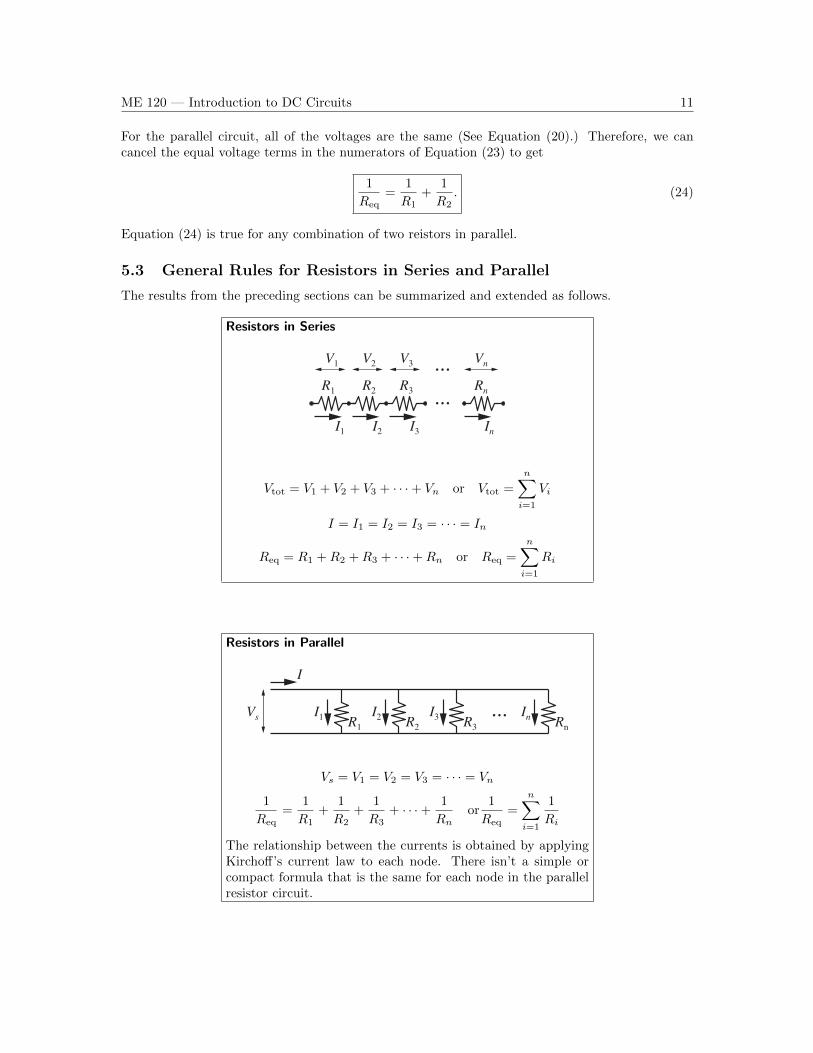
5.3 General Rules for Resistors in Series and Parallel
The results from the preceding sections can be summarized and extended as follows.
Resistors in Series
V1
R1
I1
RnR3R2
I2 I3 In
V2 V3 Vn
...
...
Vtot = V1 + V2 + V3 + · · ·+ Vn or Vtot =
n∑i=1
Vi
I = I1 = I2 = I3 = · · · = In
Req = R1 +R2 +R3 + · · ·+Rn or Req =
n∑i=1
Ri
Resistors in Parallel
Vs R1I1 R2
I2 R3I3 Rn
In
I
...
Vs = V1 = V2 = V3 = · · · = Vn
1
Req=
1
R1+
1
R2+
1
R3+ · · ·+ 1
Rnor
1
Req=
n∑i=1
1
Ri
The relationship between the currents is obtained by applyingKirchoff’s current law to each node. There isn’t a simple orcompact formula that is the same for each node in the parallelresistor circuit.

ME 120 — Introduction to DC Circuits 12
6 Summary
1. Ohm’s Law relates the flow of current to the voltage drop across a resistor.
V = IR
where V is the voltage (in volts, V ), I is the current (in amp, A) and R is the resistance (inohm, Ω).
Notes:
• V is used for both a voltage value and the units of volts.
• A “resistor” can be any element that conducts electricity, e.g.,, a length of wire, a resistorin a circuit, or the filament of an incandescent light bulb.
2. At a basic physical level, current is defined as a flow of electrons
1 A =1 C
1 s=
1 coulomb
1 second
where coulomb is the unit of charge.
At a basic physical level, voltage is the amount of energy associated with the separation ofopposite charges
1 V =1 J
1 C=
1 joule
1 coulomb
In terms of resistivity, an intrinsic property of conductors, the macroscopic resistance of a wire(or any long and relatively skinny conductor) is
R =ρL
A
where ρ is the resistivity, L is the length of the wire, and A is the cross-sectional area of thewire.
3. Work and energy are amounts. Power is a rate
Work and energy can be defined in terms of raising a mass of material against the accelerationof gravity. The amount of mechanical work done in raising a mass, m, by a distance, d, is
Work = force× distance = mgd.
where g is the acceleration of gravity. The work done is equivalent to the change in potentialenergy of the mass
Change in potential energy = mgd.
Power is the rate at which work is done.
Power =work
time=
energy
time.
Raising the mass m through a distance d always takes the same amount of work. However,raising it quickly takes more power than raising it slowly.

ME 120 — Introduction to DC Circuits 13
4. Power dissipated in a resistor can be computed by three equivalent formulas
P = V I, P = I2R, P =V 2
R.
We usually write these separate formulas in a single line as
P = V I = I2R =V 2
R.
5. The equivalent resistance of two resistors in series is
Two resistors in series: Req = R1 +R2.
The equivalent resistance of two resistors in parallel is
Two resistors in parallel:1
Req=
1
R1+
1
R2.
Refer to Section 5.3 for cases involving more than two resistors.