1 internet technology fundamentals. 2 why study networks? integral part of society work,...
TRANSCRIPT

1
Internet TechnologyFundamentals

2
Why Study Networks?
• Integral part of society• Work, entertainment, community
• Pervasive • Home, car, office, school, mall …
• Understand what they do, how they work, and limitations– Any jobs left?– What happened to IT? – Future of the IT industry.
3
Impact of the Net on People
• Anytime access to remote information– HW assignments from my server
• Person-to-person and group communication– email, blogs, chat, meeting
• Form and strengthen communities – chat rooms, MUDs, newsgroups

4
Impact of the Net on Society
• Huge impact!– Continuation of technologies that reduce problems
of time & space• (e.g. railroads,phone,autos,TV)
• Good, bad and ugly – mirror of society
• Changes still on the horizon – Commerce, services, entertainment, socializing

5
Internet Roles
• Users• Everyone (mom and pop, kids)• work, leisure, serious, frivolous
• Designers• protocol design and implementation• performance, cost and scale
• Service Providers• Administrators and ISPs• Management, revenue, deployment

6
What is Internet Technology?
• What is an internet?– Network of networks
• What is the Internet?– A global internet based on the IP protocol
• To what does “Internet technology” refer?– Architecture, protocols and services

7
Sample Internet Applications
• Electronic mail• Remote terminal• File transfer• Newsgroups• File sharing• Resource distribution• World Wide Web• Video conferencing• Games

8
What is a Network?
• Carrier of information between 2 or more entities
• Interconnection may be any media capable of communicating information:– copper wire– lasers– microwave– satellite link

9
Some Definitions
– Network: Collection of interconnected machines– Host: Machine running user application– Channel: Logical line of communication– Media: Physical process used – Protocol: Rules of communication– Router: decide were to send data next– Topology: How network is interconnected

10
How Do Computers Communicate?
• With 1’s and 0’s– Computers only deal with 1’s and 0’s– So do networks– Must build all further structures from this basic
representation
• How do we transmit 1’s and 0’s in a network?
11
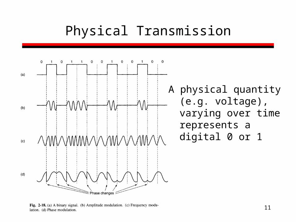
Physical Transmission
A physical quantity (e.g. voltage), varying over time represents a digital 0 or 1

12
Concepts for this week
• Layering and encapsulation– IP Hourglass
• Core and Edge of the Internet • Circuit, message and packet switching • Single link transmission delay• Multi-link transmission delay
– Circuit switching– Message switching – Packet switching – Computing general pipelining delay

13
Layering and Encapsulation
14
Why Layering?
• Network communication is very complex• Separation of concerns
– Different vendors and organizations responsible for different layers
– Testing and maintenance is simplified– Easy to replace a single layer with a different
version
15
Protocol Hierarchy
• Use layers to hide complexity– Each layer implements a service
• Layer N uses service provided by layer N-1• layer N-1 provides a service to layer N
– Protocols• Each layer communicates with its peer by a set of rules
• Interface– A layers interface specifies the operations
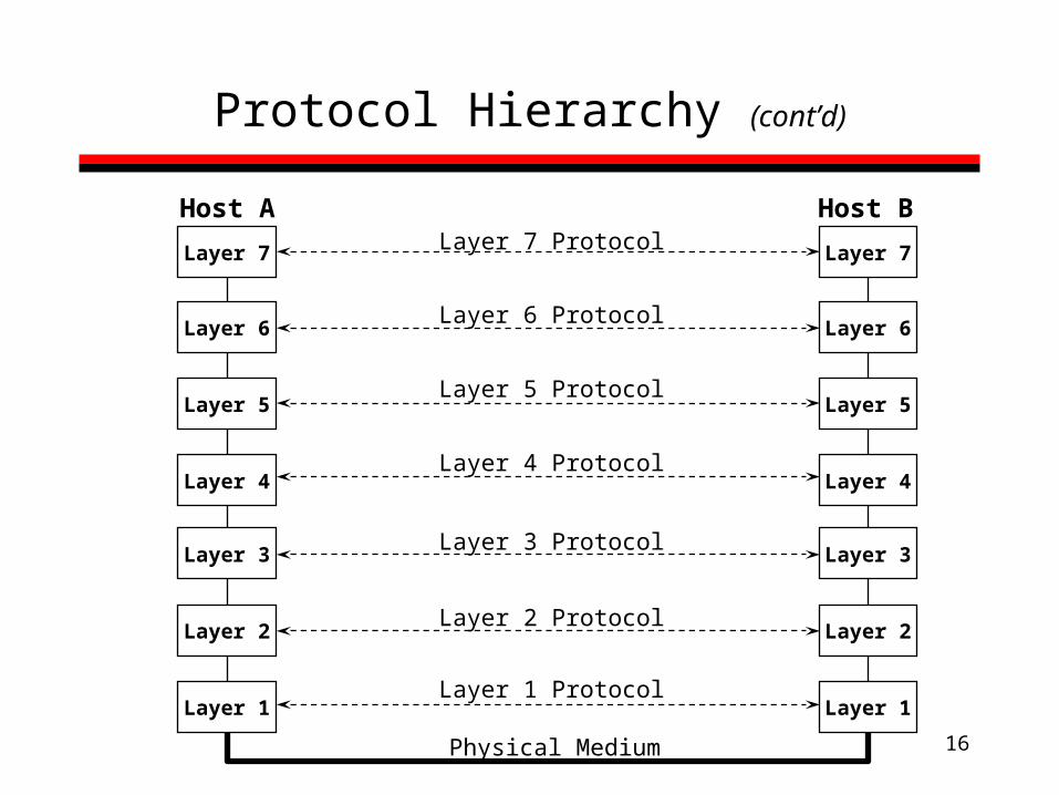
16
Protocol Hierarchy (cont’d)
Layer 7
Layer 6
Layer 5
Layer 4
Layer 3
Layer 2
Layer 1
Layer 7
Layer 6
Layer 5
Layer 4
Layer 3
Layer 2
Layer 1
Layer 7 Protocol
Layer 4 Protocol
Layer 3 Protocol
Layer 2 Protocol
Layer 6 Protocol
Layer 1 Protocol
Layer 5 Protocol
Physical Medium
Host A Host B
17
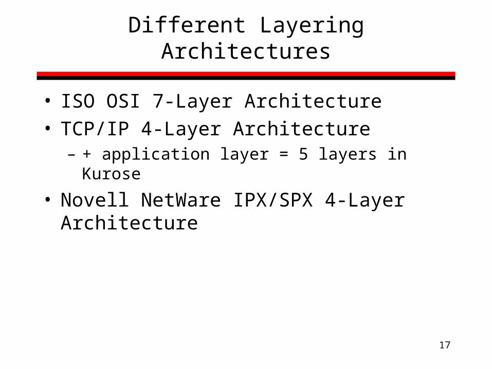
Different Layering Architectures
• ISO OSI 7-Layer Architecture• TCP/IP 4-Layer Architecture
– + application layer = 5 layers in Kurose
• Novell NetWare IPX/SPX 4-Layer Architecture

18
Standards Making Organizations
ISO = International Standards Organization
ITU = International Teletraffic Union (formerly CCITT)
ANSI = American National Standards Institute
IEEE = Institute of Electrical and Electronic Engineers
IETF = Internet Engineering Task Force
ATM Forum = ATM standards-making body
...and many more

19
Why So Many Standards Organizations?
• Multiple technologies• Different areas of emphasis and history
– Telecommunications/telephones• ITU,ISO,ATM
– Local area networking/computers• IETF, IEEE
– System area networks/storage • ANSI
20
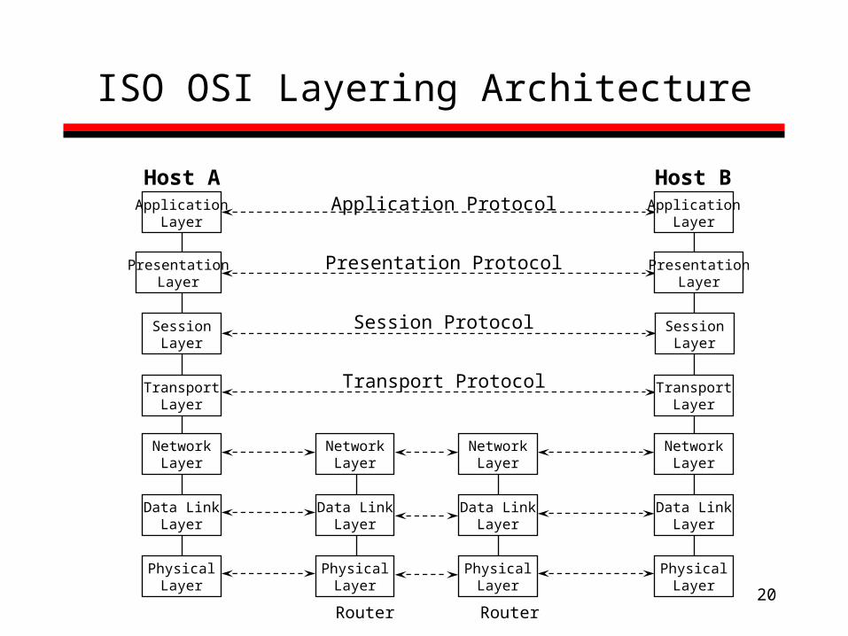
ISO OSI Layering Architecture
ApplicationLayer
PresentationLayer
SessionLayer
TransportLayer
NetworkLayer
Data LinkLayer
PhysicalLayer
Application Protocol
Transport Protocol
Presentation Protocol
Session Protocol
Host A Host BApplication
Layer
PresentationLayer
SessionLayer
TransportLayer
NetworkLayer
Data LinkLayer
PhysicalLayer
NetworkLayer
Data LinkLayer
PhysicalLayer
NetworkLayer
Data LinkLayer
PhysicalLayer
Router Router
21
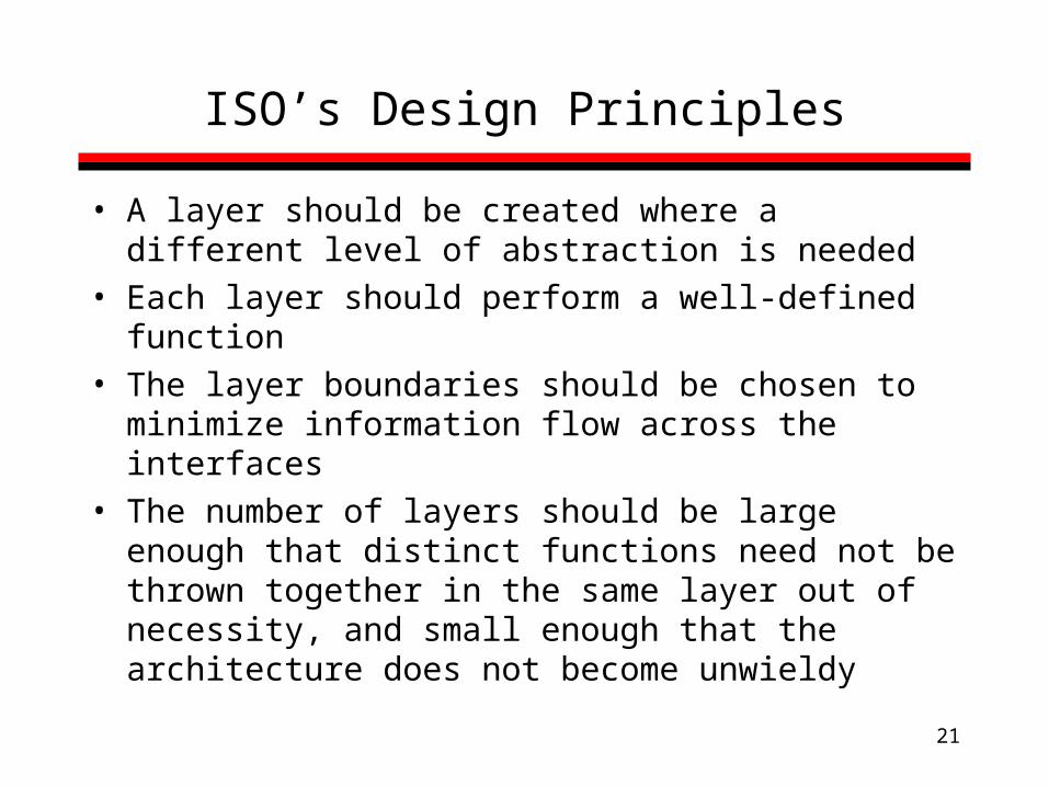
ISO’s Design Principles
• A layer should be created where a different level of abstraction is needed
• Each layer should perform a well-defined function• The layer boundaries should be chosen to minimize
information flow across the interfaces• The number of layers should be large enough that
distinct functions need not be thrown together in the same layer out of necessity, and small enough that the architecture does not become unwieldy
22
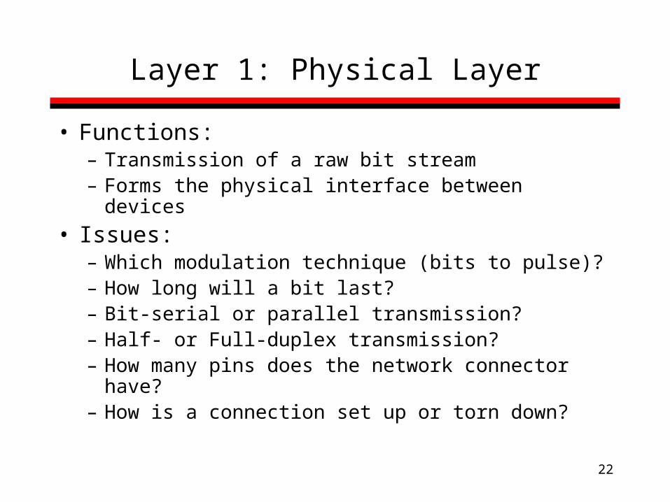
Layer 1: Physical Layer
• Functions:– Transmission of a raw bit stream– Forms the physical interface between devices
• Issues:– Which modulation technique (bits to pulse)?– How long will a bit last?– Bit-serial or parallel transmission?– Half- or Full-duplex transmission?– How many pins does the network connector have?– How is a connection set up or torn down?

23
Layer 2: Data Link Layer
• Functions:– Provides reliable transfer of information between
two adjacent nodes– Creates frames, or packets, from bits and vice
versa– Provides frame-level error control– Provides flow control
• In summary, the data link layer provides the network layer with what appears to be an error-free link for packets
24
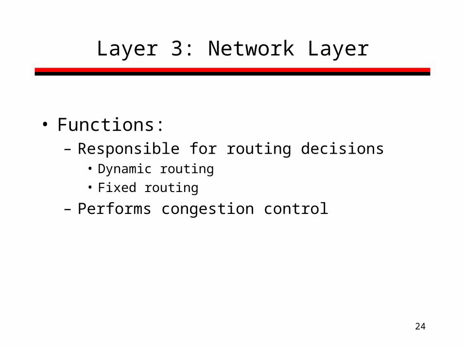
Layer 3: Network Layer
• Functions:– Responsible for routing decisions
• Dynamic routing• Fixed routing
– Performs congestion control

25
Layer 4: Transport Layer
• Functions:– Hide the details of the network from the session layer
• Example: If we want replace a point-to-point link with a satellite link, this change should not affect the behavior of the upper layers
– Provides reliable end-to-end communication

26
ApplicationLayer
PresentationLayer
SessionLayer
TransportLayer
NetworkLayer
Data LinkLayer
PhysicalLayer
Application Protocol
Transport Protocol
Presentation Protocol
Session Protocol
Host A Host BApplication
Layer
PresentationLayer
SessionLayer
TransportLayer
NetworkLayer
Data LinkLayer
PhysicalLayer
NetworkLayer
Data LinkLayer
PhysicalLayer
NetworkLayer
Data LinkLayer
PhysicalLayer
Router Router
Transport Layer (cont’d)
firstend-to-end
layer

27
Transport Layer (cont’d)
• Functions (cont’d):– Perform end-to-end flow control– Perform packet retransmission when packets are
lost by the network

28
Layer 5: Session Layer
• May perform synchronization between several communicating applications or logical transmissions
• Groups several user-level connections into a single “session”
• Examples: – Banking session– Network meetings
29
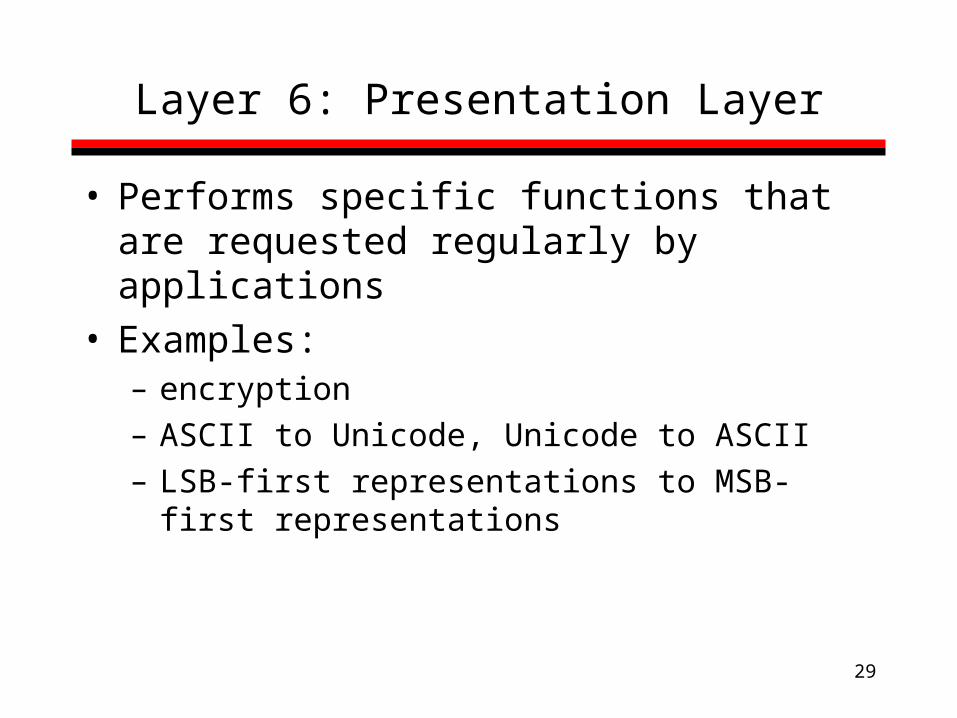
Layer 6: Presentation Layer
• Performs specific functions that are requested regularly by applications
• Examples:– encryption– ASCII to Unicode, Unicode to ASCII– LSB-first representations to MSB-first
representations

30
Layer 7: Application Layer
• Application layer protocols are application-dependent
• Implements communication between two applications of the same type
• Examples:– FTP– Quake – SMTP (email)

31
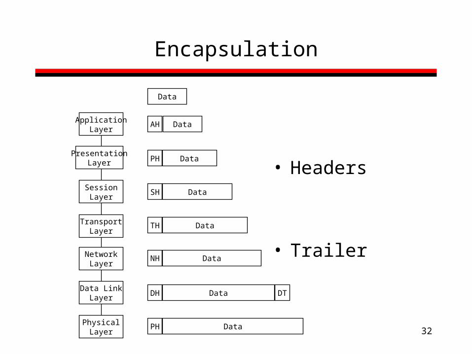
Encapsulation
Treat the neighboring layer’s information as a “black box”, can’t look inside or break message
• Sending: add information needed by the current layer “around” the higher layers’ data – headers in front– trailers in back
• Receiving: Strip off headers and trailers before handing up the stack
32
Encapsulation
• Headers
• Trailer
ApplicationLayer
PresentationLayer
SessionLayer
TransportLayer
NetworkLayer
Data LinkLayer
PhysicalLayer
Data
DataAH
DataPH
DataSH
DataTH
DataNH
DataDH DT
DataPH
33
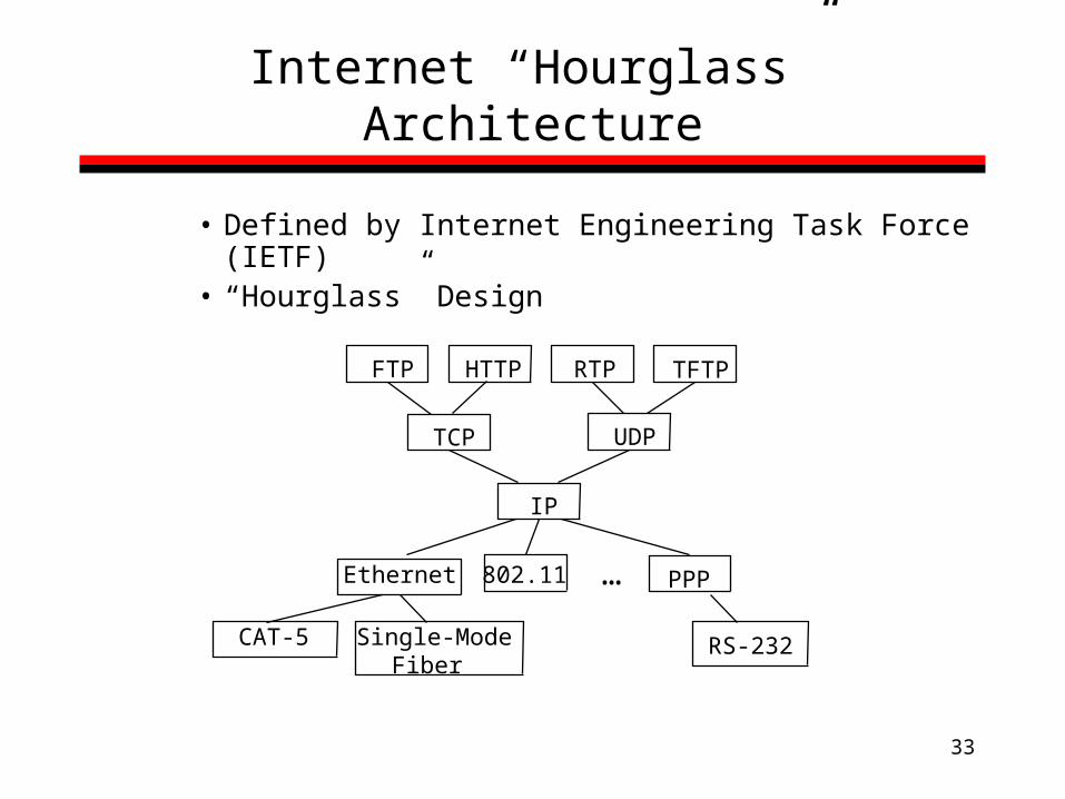
Internet “Hourglass” Architecture
• Defined by Internet Engineering Task Force (IETF)• “Hourglass” Design
…
FTP HTTP RTP TFTP
TCP UDP
IP
Ethernet 802.11 PPP
CAT-5 Single-ModeFiber
RS-232
34
Internet Design Principles
– Scale• Protocols should work in networks of all sizes and
distances
– Incremental deployment• New protocols need to be deployed gradually
– Heterogeneity• Different technologies, autonomous organizations
– End-to-end argument• Some functions can only be correctly implemented at the
end hosts; the network should not provided these.
35
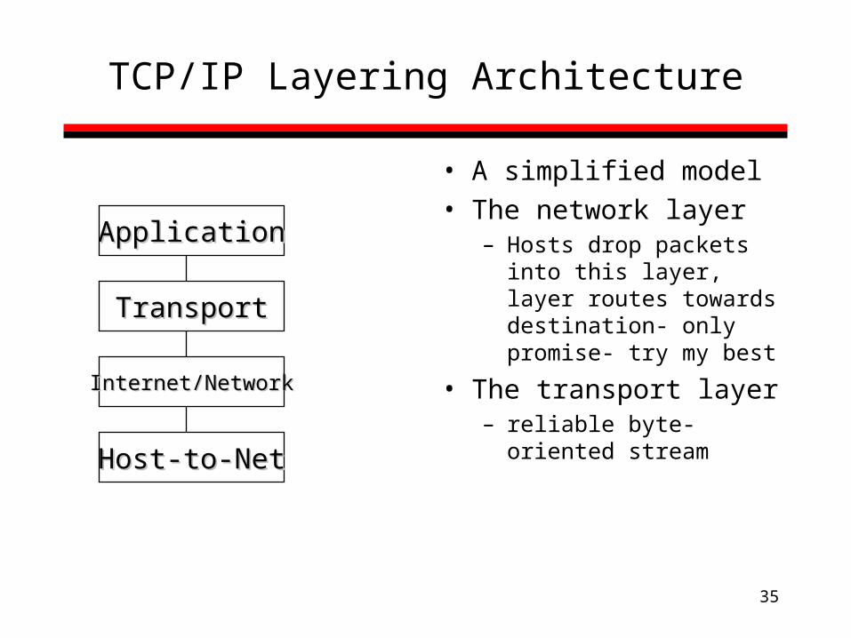
TCP/IP Layering Architecture
• A simplified model• The network layer
– Hosts drop packets into this layer, layer routes towards destination- only promise- try my best
• The transport layer– reliable byte-oriented
stream
ApplicationApplication
TransportTransport
Internet/NetworkInternet/Network
Host-to-NetHost-to-Net

36
TCP/IP Layering Architecture (cont’d)
Application Protocol
Transport Protocol (TCP)
ApplicationLayer
TransportLayer
NetworkLayer
Host-to-Net Layer
Host A Host BApplication
Layer
TransportLayer
NetworkLayer
Host-to-Net Layer
NetworkLayer
Host-to-Net Layer
NetworkLayer
Host-to-Net Layer
IPIP IP
37
Internet Topology
• Current structure divides network into the “core” and “edge” networks
• Core ISP’s “tiers” – Tier 1: Biggest ISPs
• E.g. MCI, Sprint, AT&T
– Tier 2 and 3: Regional and very small.
• Edges: – Companies, organizations with a “default route”
• E.g. Rutgers

38
Edge Networks
Company A
Company B
Internet Service Provider 1
ISP 2
Edge router

39
Core Networks
Company A
Company B
Internet Service Provider 1
ISP 2

40
Single link Network Performance
A Brief Introduction

41
Why Study Network Performance
• Networks cost $– OC-3 line ~= $10,000/month
– Cable modem: $40/month
– Are you getting your $/worth?
• Why is the network “slow”?• Approach:
– Build abstract models of network performance
– Observe where real networks deviate from model
– Simple Models: Tells us average/best/worse cases->useful, practical
– Complex Models: Hard to understand -> useless
42
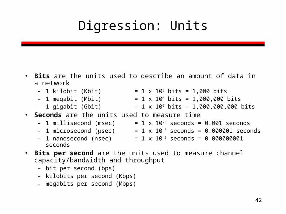
Digression: Units
• Bits are the units used to describe an amount of data in a network– 1 kilobit (Kbit) = 1 x 103 bits = 1,000 bits– 1 megabit (Mbit) = 1 x 106 bits = 1,000,000 bits– 1 gigabit (Gbit) = 1 x 109 bits = 1,000,000,000 bits
• Seconds are the units used to measure time– 1 millisecond (msec) = 1 x 10⁻³ seconds = 0.001 seconds– 1 microsecond (sec) = 1 x 10⁻⁶ seconds = 0.000001 seconds– 1 nanosecond (nsec) = 1 x 10⁻⁹ seconds = 0.000000001
seconds
• Bits per second are the units used to measure channel capacity/bandwidth and throughput
– bit per second (bps)– kilobits per second (Kbps)– megabits per second (Mbps)

43
Types of Delay
• Processing– Time to execute protocol code
• Queuing– Time waiting in queue to be processed
• Transmission– Time to “get bits on wires”
• Propagation – Time for bits to “move across wires”

44
Some Definitions
• Packet length: size of a packet (units = bits or bytes)• Channel speed: How fast the channel can transmit bits (units =
bits/second)• Packet transmission time: amount of time to transmit an entire
packet (units = seconds)• Propagation delay: Delay imposed by the properties of the link.
Depends on the link’s distance (units = seconds)

45
Transmission vs. Prop. delay
A single transmission link as a water pipe
1. The thicker the pipe, the more water it can carry from one end to the other
2. Water is carried from one end of the pipe to the other at constant speed, no matter how thick the pipe is
Water = Data bits
Thickness of the pipe = Channel capacity
Speed of water through the pipe = Propagation delay
46
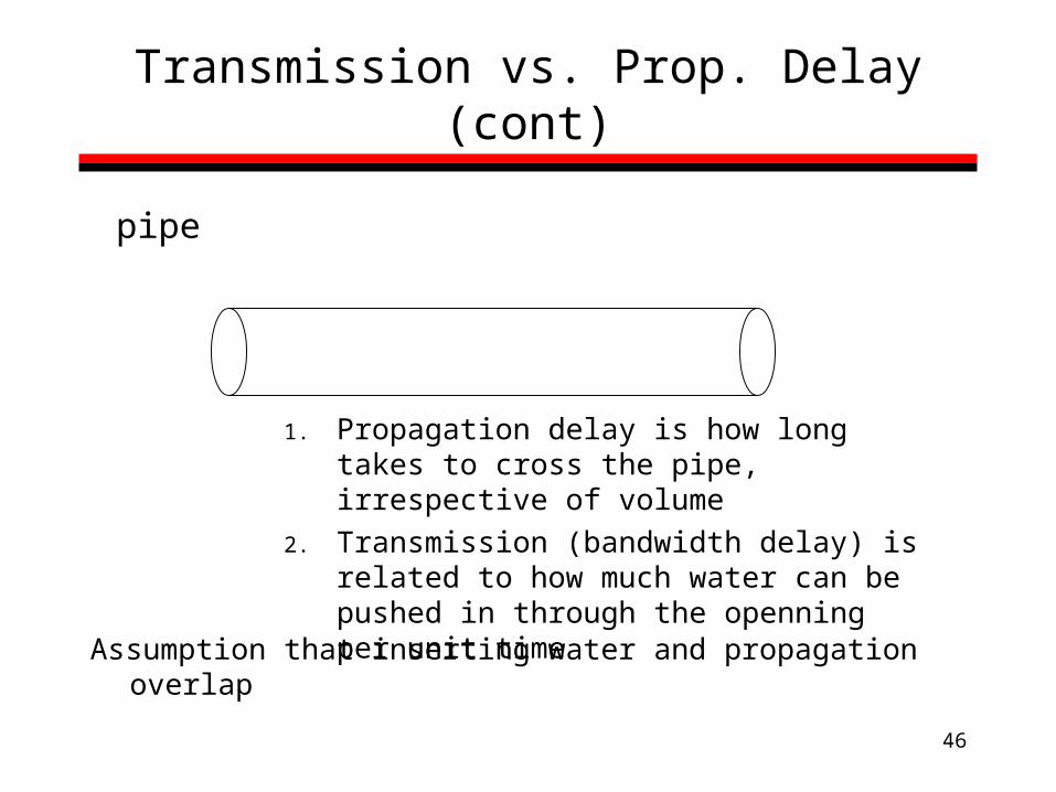
Transmission vs. Prop. Delay (cont)
pipe
1. Propagation delay is how long takes to cross the pipe, irrespective of volume
2. Transmission (bandwidth delay) is related to how much water can be pushed in through the openning per unit time
Assumption that inserting water and propagation overlap

47
1500 x 8 bits
Transmission Time
How long does it take A to transmit an entire packet onto the link?
Relevant information: packet length = 1500 bytes channel capacity = 100 Mbps
Another way to ask this question:If the link can transmit 10 million bits in a second, how many seconds does it take to transmit 1500 bytes (8x1500 bits)?
100 Mbits
1 sec=
t
Solving for t… t = 0.00012 sec (or 120 sec)

48
Propagation Delay
How long does it take a single bit to travel on the link from A to B?
Relevant information: link distance = 500 m prop. delay factor = 5 sec/km
Another way to ask this question:If it takes a signal 5 sec to travel 1 kilometer, then how long does it take a signal to travel 500 meters?
5 sec
1000 m=
500 m
t Solving for t…t = 2.5 sec
49
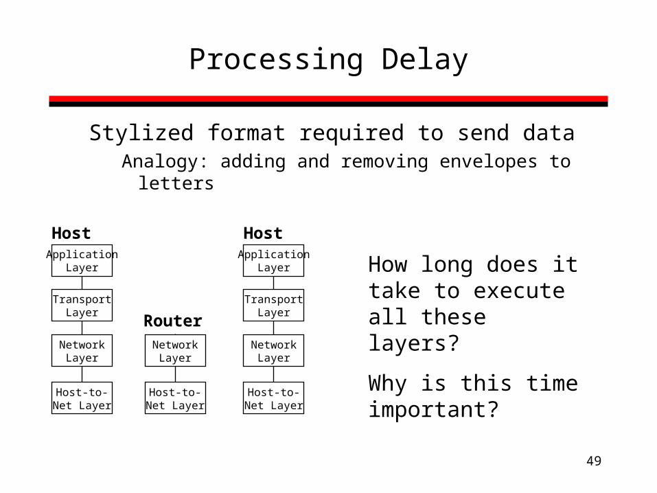
Processing Delay
Stylized format required to send dataAnalogy: adding and removing envelopes to letters
ApplicationLayer
TransportLayer
NetworkLayer
Host-to-Net Layer
Host
How long does it take to execute all these layers?
Why is this time important?
NetworkLayer
Host-to-Net Layer
Router
ApplicationLayer
TransportLayer
NetworkLayer
Host-to-Net Layer
Host

50
Example
Protocol Processing Time = 40 sec
packet length = 1500 bytes
channel capacity = 100 Mbps
propagation delay factor = 5 sec/km
A B
500 m
1. How long to format the data?
2. How long does it take a single bit to travel on the link from A to B?
3. How long does it take A to transmit an entire packet onto the link?

51
Timeline Method
Time
Protocol Delay
Transmission time
Propagation delay
Protocol Delay
Host A Host B
40
2.5
120
40
1st bit
last bit
Total time: 40+120+2.5+40 = 202.5 sec

52
Queuing Delay
NetworkLayer
Host-to-Net Layer
Router
Packets arriving faster than processing or transmission delay
=> queuing (I.e. waiting in line)
Router
0300
2
1
0123
0
2
Packets waiting processing at input ports
Packets waiting transmission at output ports
53
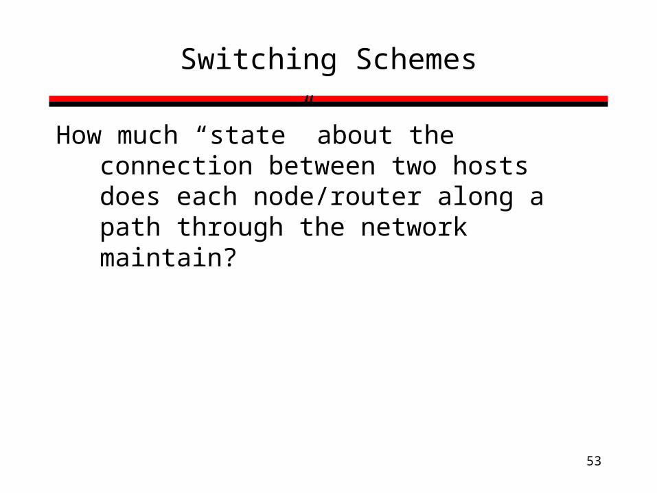
Switching Schemes
How much “state” about the connection between two hosts does each node/router along a path through the network maintain?
54
Switching Schemes
(1) Circuit Switching
(2) Message Switching (Store-and-Forward)
(3) Packet Switching (Store-and-Forward)
55
Circuit Switching
• Provides service by setting up the total path of connected lines hop-by-hop from the origin to the destination
• Example: Telephone network
56
Circuit Switching (cont’d)
1. Control message sets up a path from origin to destination
2. Return signal informs source that data transmission may proceed
3. Data transmission begins
4. Entire path remains allocated to the transmission (whether used or not)
5. When transmission is complete, source releases the circuit

57
Circuit Switching (cont’d)T
ime
A B C D
Data
Call accept signal
Call request signal
DataTransmission
Time
Propagation Delay
Routers/Switches
TransmissionDelay
58
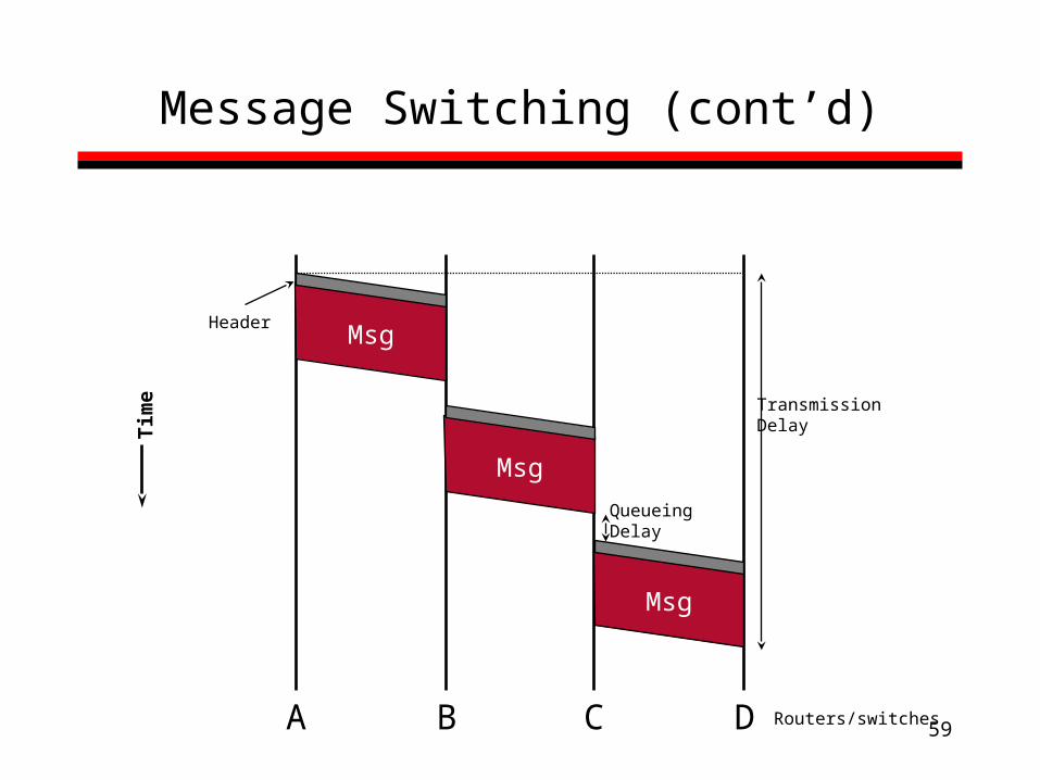
Message Switching
• Each message is addressed to a destination• When the entire message is received at a router, the
next step in its journey is selected; if this selected channel is busy, the message waits in a queue until the channel becomes free
• Thus, the message “hops” from node to node through a network while allocating only one channel at a time
• Analogy: Postal service
59
Message Switching (cont’d)T
ime
A B C D
Msg
Msg
Msg
QueueingDelay
Routers/switches
TransmissionDelay
Header

60
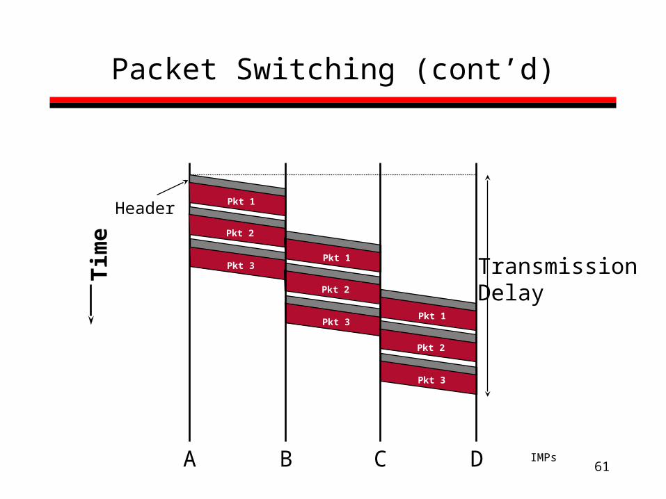
Packet Switching
• Messages are split into smaller pieces called packets
• These packets are numbered and addressed and sent through the network one at a time
• Allows Pipelining– Overlap sending and receiving of packets on multiple links
61
Packet Switching (cont’d)T
ime
A B C D IMPs
Pkt 1
Pkt 2
Pkt 3Pkt 1
Pkt 2
Pkt 3Pkt 1
Pkt 2
Pkt 3
TransmissionDelay
Header

62
Comparisons
(1) Header Overhead
Circuit < Message < Packet
(2) Transmission Delay
Short Bursty Messages:
Packet < Message < Circuit
Long Continuous Messages:
Circuit < Message < Packet

63
Analytic Comparison
• Given choice of 2 switching schemes, how would you compare their performance?– What would you need to know? – What are the independent variables?– What is the dependent variable?
• Could you come up with a closed form expression based on your choices?
64
Example: Circuit Switching vs. Packet Switching
• Goal: Determine which is faster– Formal definition: Least time to move a fixed
amount of data
• Approach: – Compute time where circuit switching and packet
switching are equal based on all possible factors – A factor moving in one direction or the other will tip
the balance in favor of one or the other– We’ll ignore wire-line propagation delay in this
example

65
Factors:
• Number of bytes in the message: N• Time to set up circuit: c• Per-link bandwidth: B• Size of the packet: p • Size of the header: h • Number of switches: s
66
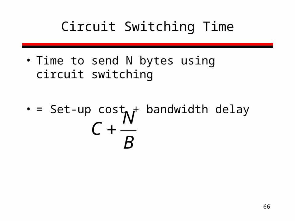
Circuit Switching Time
• Time to send N bytes using circuit switching
• = Set-up cost + bandwidth delay
C N
B
67
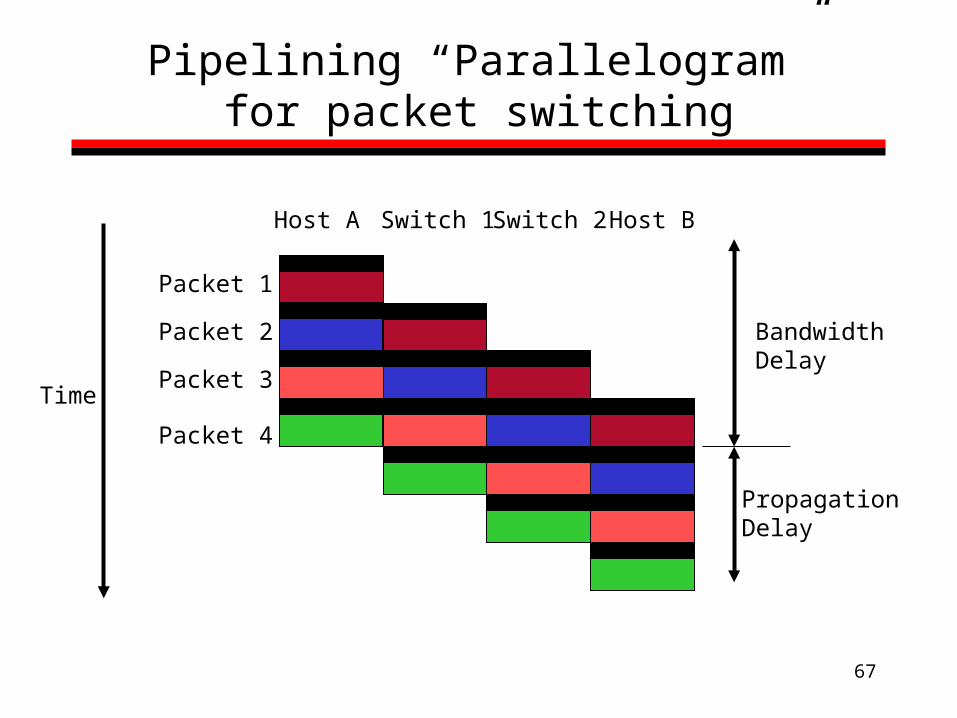
Pipelining “Parallelogram” for packet switching
Time
Host A Switch 1 Switch 2 Host B
Bandwidth Delay
Propagation Delay
Packet 1
Packet 2
Packet 3
Packet 4

68
Note on Pipelining
• The above analysis is very general: – Packets in a computer network
• Messages/packets are the unit of work.
– Instructions in a processor• Instructions are the unit of work.
– Jobs through a batch Q in an operating system.• Processes are the unit of work.
• Pipelining speeds up work over time. – How?

69
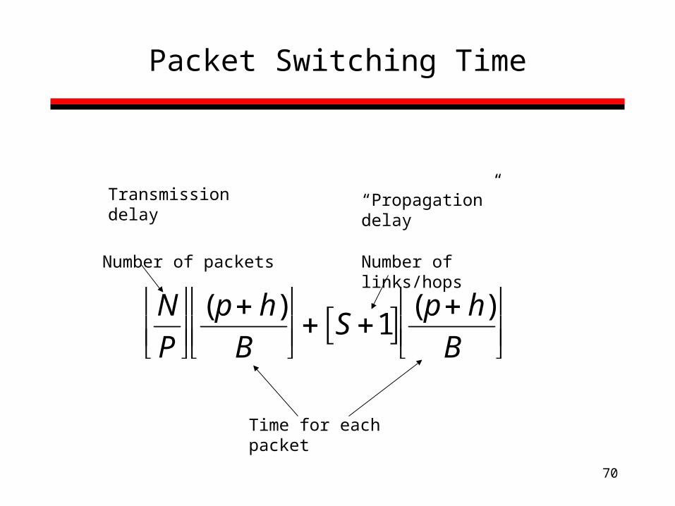
Packet Switching Time
Transmission delay (also bandwidth delay): Time to push all the packets into the network
+ “Propagation” delay: Time for the last packet to cross
- not really prop. delay in the traditional sense
Delay = Transmission + “Propagation” delays
N
P
(p h)B
S 1 (p h)
B
70
Packet Switching Time
N
P
(p h)B
S 1 (p h)
B
Number of packets Number of links/hops
Time for each packet
Transmission delay “Propagation” delay

71
Equilibrium Point
C N
B
p hB
N
P
S 1
Assuming all other factors equal, solve for C
Q: Can you add link propagation delay to this example?
72
Homework Questions
• If we use message switching, how does the time increase as we scale s?
• How does packet switching reduce the impact of increasing s?
• Show, using an equation, how reducing the packet size and packet switching reduces the impact of increasing s.
• Where does the approach of reducing packet size fail to give any benefit?