1 integrated services digital network u public networks are used for a variety of services –public...
Post on 22-Dec-2015
215 views
TRANSCRIPT

1
Integrated Services Digital Network
Public networks are used for a variety of services– Public Switched Telephone Network– Private Lines (leased)– Packet Switched Data Networks– Circuit Switched Data networks
2
ISDN
Users have a variety of equipment to connect to public networks– Telephones– Private Branch Exchanges– Computer Terminals or PCs– Mainframe Computers
A variety of physical interfaces and access procedures are required for connection

3
ISDN
The telephone network has evolved into a digital one with digital exchanges and links
The signalling system has become a digital message-oriented common channel signalling system (SS#7)
The term ‘Integrated Digital Network’ is used to describe these developments

4
ISDN
The Public Switched Telephone network is still analogue from the subscriber to the local exchange
The need has arisen to extend the digital network out to subscribers and to provide a single standardised interface to all different users of public networks
ISDN fulfils that need
5
Integrated Services Digital Network
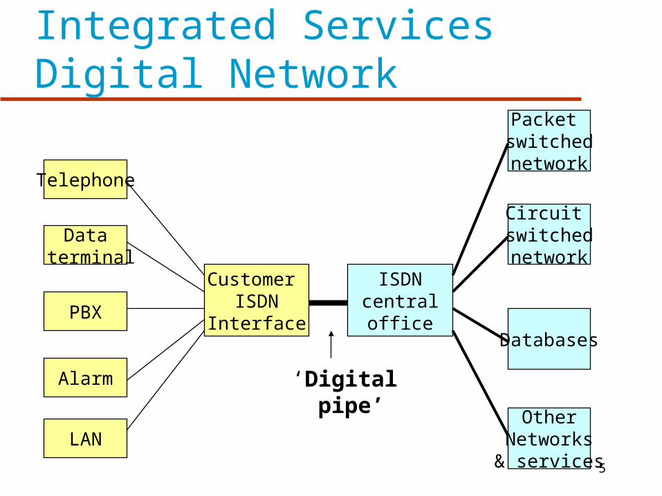
Telephone
Data terminal
PBX
Alarm
LAN
Customer ISDN
Interface
ISDNcentraloffice
Packet switchednetwork
Circuit switchednetwork
Databases
OtherNetworks& services
‘Digital pipe’
6
ISDN
In Practice there are multiple networks providing the service nationally
The user however, sees a single network

7
Benefits to Subscribers
Single access line for all services Ability to tailor service purchased to suit
needs Competition among equipment vendors due
to standards Availability of competitive service
providers
8
Architecture
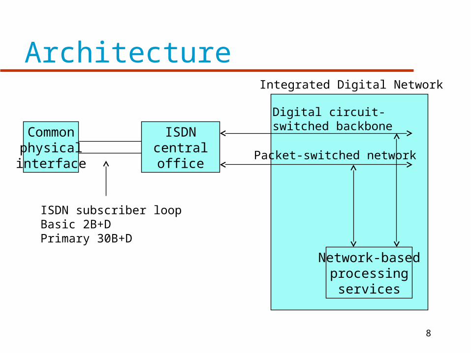
Commonphysicalinterface
ISDNcentraloffice
Network-basedprocessing
services
Digital circuit-switched backbone
Packet-switched network
Integrated Digital Network
ISDN subscriber loopBasic 2B+DPrimary 30B+D
9
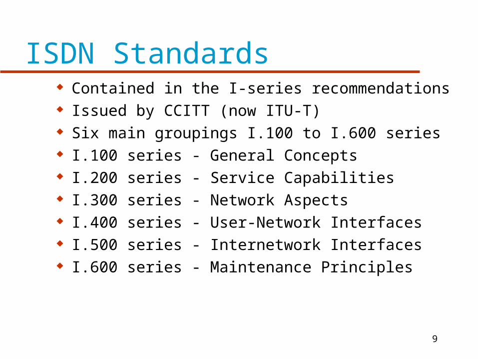
ISDN Standards Contained in the I-series recommendations Issued by CCITT (now ITU-T) Six main groupings I.100 to I.600 series I.100 series - General Concepts I.200 series - Service Capabilities I.300 series - Network Aspects I.400 series - User-Network Interfaces I.500 series - Internetwork Interfaces I.600 series - Maintenance Principles
10
ISDN Channels
The Digital pipe is made up of channels - one of three types
B channel, D channel or H channel Channels are grouped and offered as a
package to users
11
B Channel
B channel-64 kbps B is basic user channel
– can carry digital data or PCM-encoded voice – or mixture of lower rate traffic.
12
B Channel
Four kinds of connection possible Circuit-switched Packet-switched - X.25 Frame mode - frame relay (LAPF) Semipermanent - equivalent to a leased line
13
D Channel
D Channel - 16 or 64 kbps Carries signalling information to control
circuit-switched calls on B channels Can also be used for packet switching or
low-speed telemetry

14
H Channel
Carry user information at higher bit rates 384kbps or 1536kbps or 1920kbps
Can be used as a high-speed trunk Can also be subdivided as per user’s own
TDM scheme Uses include high speed data, fast
facsimile, video, high-quality audio
15
ISDN Channels and their Applications
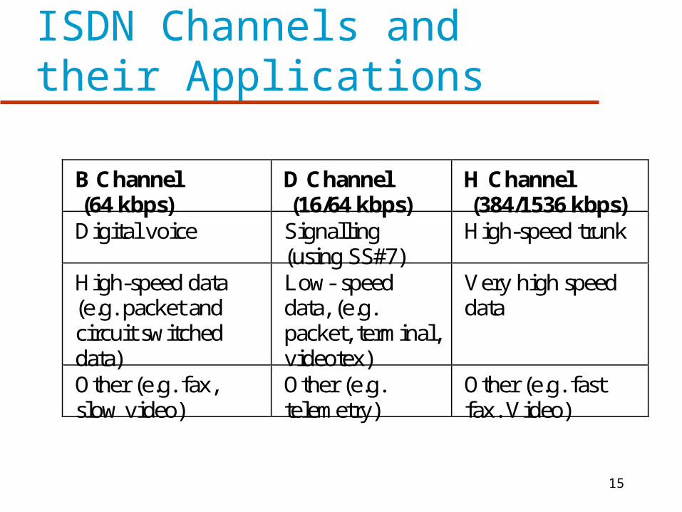
B Channel (64 kbps)
D Channel (16/64 kbps)
H Channel (384/1536 kbps)
Digital voice Signalling(using SS#7)
High-speed trunk
High-speed data(e.g. packet andcircuit switcheddata)
Low- speeddata, (e.g.packet, terminal,videotex)
Very high speeddata
Other (e.g. fax,slow video)
Other (e.g.telemetry)
Other (e.g. fastfax. Video)
16
ISDN Channel Groupings
Basic Access - two 64 kbps B channels plus one 16kbps D channel B channels can be used for voice and data simultaneous calls to separate destinations
supported D channel used for signalling and also for data
using X.25
17
ISDN Basic Access
Intended for small business and residential use
A single physical interface is provided Data rate is 144kbps plus 48kbps overhead
bits totalling 192 kbps Most existing subscriber loops can support
basic access
18
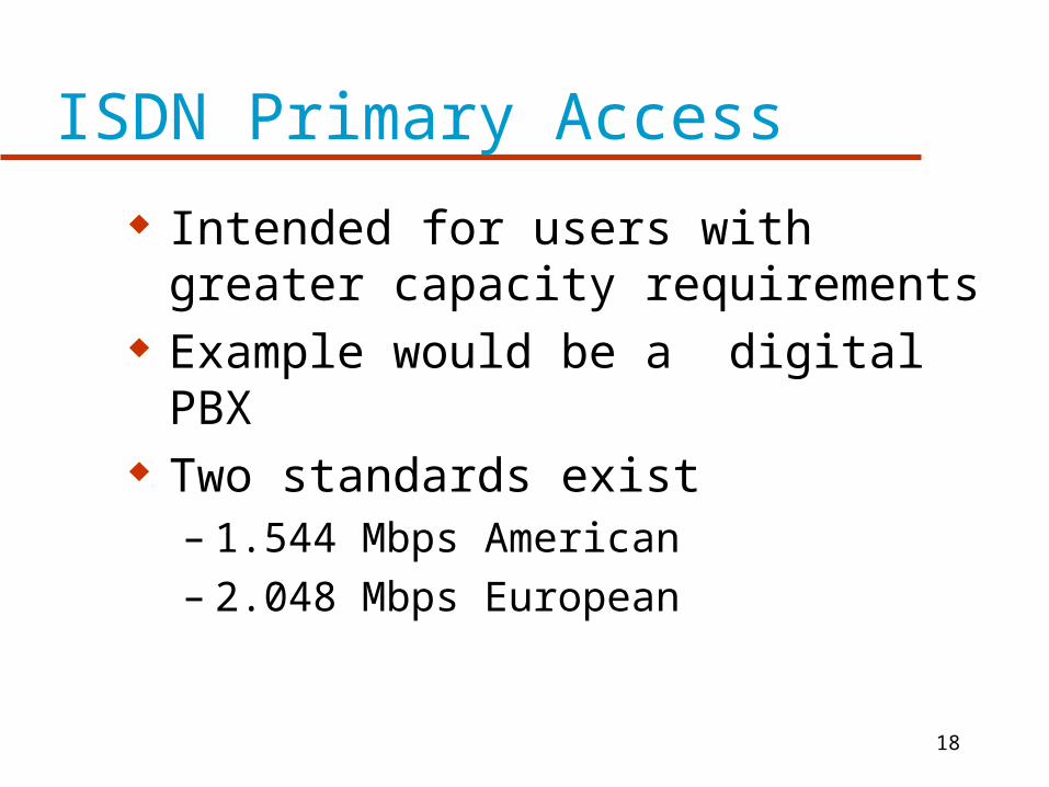
ISDN Primary Access
Intended for users with greater capacity requirements
Example would be a digital PBX Two standards exist
– 1.544 Mbps American– 2.048 Mbps European
19
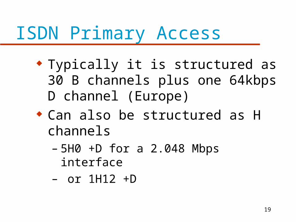
ISDN Primary Access
Typically it is structured as 30 B channels plus one 64kbps D channel (Europe)
Can also be structured as H channels– 5H0 +D for a 2.048 Mbps interface– or 1H12 +D
20
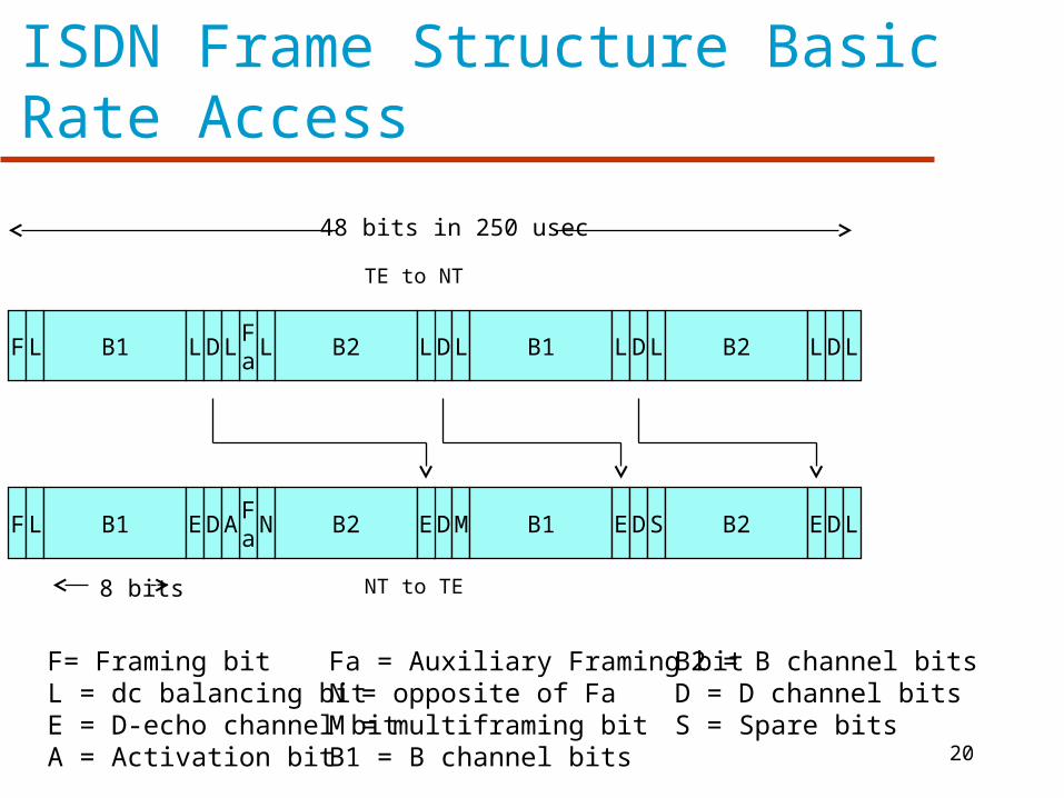
ISDN Frame Structure Basic Rate Access
F L B1 LDFa
L L B2 DL L B1 LDL B2 LDL
F L B1 EDFa
A N B2 DE M B1 EDS B2 EDL
48 bits in 250 usec
TE to NT
NT to TE8 bits
F= Framing bitL = dc balancing bitE = D-echo channel bitA = Activation bit
Fa = Auxiliary Framing bitN = opposite of FaM = multiframing bitB1 = B channel bits
B2 = B channel bitsD = D channel bitsS = Spare bits

21
ISDN Contention Resolution
Several TE’s can share a single line How is contention resolved? B-channel Traffic
– No contention as each channel dedicated to particular TE
D - Channel used for data and control so requires a contention resolution mechanism

22
D Channel Contention
Incoming Traffic – LAPD protocol resolves contention
Outgoing Traffic – Multiple devices share D channel– Contention resolution algorithm required
23
D Channel Contention
Idle TEs sends binary 1s on D channel This means no signal (pseudoternery) NT echos received binary value back as echo bit When NT wishes to send on D channel, it
listens to echo bits If it hears a string of 1’s equal in length to a
threshold value Xi, it may transmit Otherwise it must wait

24
D Channel Contention
If two TE’s start transmitting simultaneously a collision occurs
This is detected by each TE by monitoring E bits
If E bits are identical to D bits sent then no collision
If discrepency detected TE stops and listens

25
D Channel Contention
Priority mechanisms based on threshold values– Control information has priority over user data– When TE has sent data its priority is lowered
until other terminals transmit

26
D Channel Priorities
Control Information– Normal Priority X1 =8– Lower Priority X1 =9
User Data– Normal Priority X2 =10– Lower Priority X2 =11
27
ISDN Primary Interface
Multiple channels multiplexed on single medium
Only point to point configuration is allowed Typically supports a digital PBX and
provides a synchronous TDM facility
28
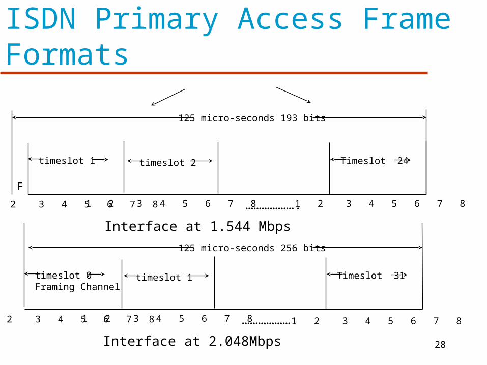
ISDN Primary Access Frame Formats
1 2 3 4 5 6 7 8 1 2 3 4 5 6 7 8 1 2 3 4 5 6 7 8
timeslot 1 timeslot 2 Timeslot 24
……………….
F
125 micro-seconds 193 bits
Interface at 1.544 Mbps
1 2 3 4 5 6 7 8 1 2 3 4 5 6 7 8 1 2 3 4 5 6 7 8
timeslot 0Framing Channel
timeslot 1 Timeslot 31
……………….
125 micro-seconds 256 bits
Interface at 2.048Mbps
29
User Access
Defined using two concepts– Functional groupings of equipment– Reference points to separate functional
groupings
30
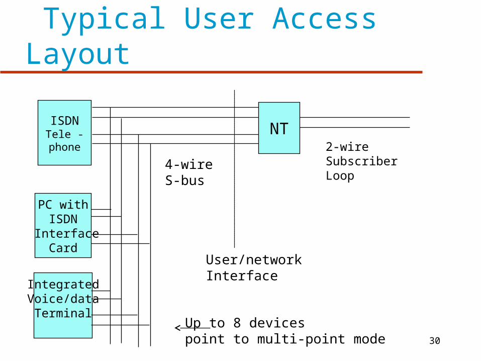
Typical User Access Layout
ISDNTele -phone
PC withISDN
InterfaceCard
NT
IntegratedVoice/dataTerminal
2-wireSubscriberLoop
User/networkInterface
4-wireS-bus
Up to 8 devices point to multi-point mode
31
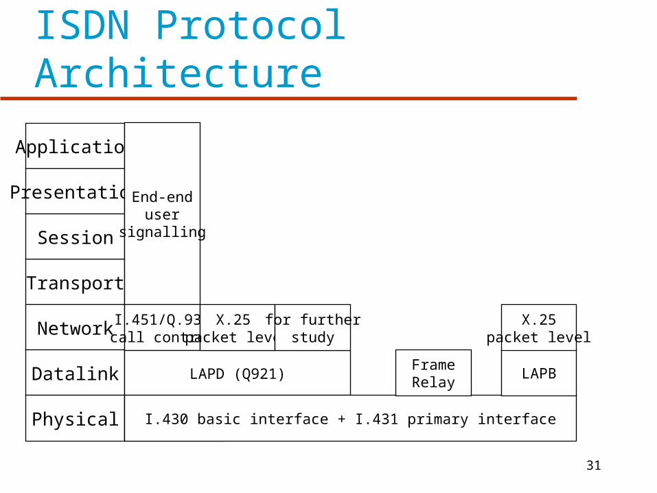
ISDN Protocol Architecture
Application
Presentation
Session
Transport
Network
Datalink
Physical
End-enduser
signalling
Physical
I.451/Q.931call control
LAPD (Q921)
I.430 basic interface + I.431 primary interface
X.25 packet level
for furtherstudy
LAPBFrameRelay
X.25packet level

32
ISDN Data Link Layer
Link Access Protocol for the D channel (LAPD) defined for ISDN
Three applications are supported– Control Signalling– Packet Switching– Telemetry
33
Network Layer Above LAPD
Control Signalling– Call Control Protocol (I.451 / Q.931)
» Establishes, maintains and terminates connections on B channels
» Possibility of user - user control signalling above this layer
34
B-Channel
Uses– Circuit Switching– Semi-permanent circuits– Packet switching
35
B-Channel
Circuit Switching– Circuit is set up on B-channel on demand– D-channel call control protocol is used– Transparent full-duplex digital data path
established between users– Layers 2 to 7 are not visible to ISDN or
specified
36
B-Channel
Semipermanent circuit can be set up by prior agreement between users and network operator
Can be for indefinite time or at specified times during day or week
As with circuit switched connection, full duplex digital data path is established
Layers 2 to 7 are not visible to ISDN or specified
37
B-Channel Packet Switching
Circuit-switched connection is established between user and packet-switched node using D-channel call control protocol
The packet switching node can be integrated into ISDN or be a separate network
User then employs X.25 layers 2 and 3 to establish virtual circuit to other user
Frame relay can also be used instead of X.25
38
D-Channel Packet Switching
Integrated X.25 service can be accessed by D-Channel in addition to B-Channel
ISDN provides a semi-permanent connection to a packet switching node within ISDN
The X.25 level 3 protocol is used for the packet layer
LAPD is used for the link layer
39
ISDN Call Control Protocol
Defined in recommendation I.451/Q.931 Network layer protocol Uses services of LAPD link layer Specifies procedures for establishing,
maintaining clearing connections on B-channels sharing D-channel
40
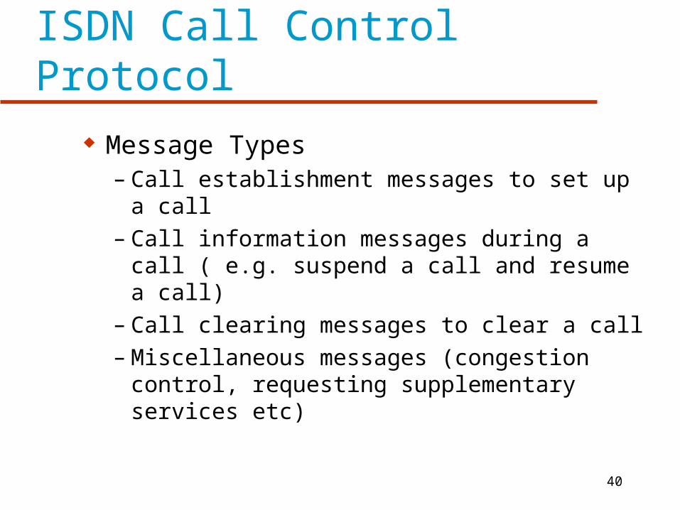
ISDN Call Control Protocol
Message Types– Call establishment messages to set up a call– Call information messages during a call ( e.g.
suspend a call and resume a call)– Call clearing messages to clear a call– Miscellaneous messages (congestion control,
requesting supplementary services etc)
41
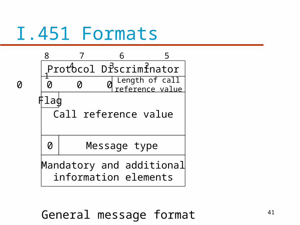
I.451 Formats
0 0 0 0 Length of callreference value
FlagCall reference value
Protocol Discriminator
Mandatory and additionalinformation elements
Message type
General message format
8 7 6 5 4 3 2 1
0

42
LAPD
Provides two types of service– Unacknowledged information transfer
» No guarantee of delivery
» Frames with error are discarded
– Acknowledged information transfer» Similar to HDLC
» Flow and error control
» Logical connection established prior to data transfer
» Also called multiple-frame operation
43
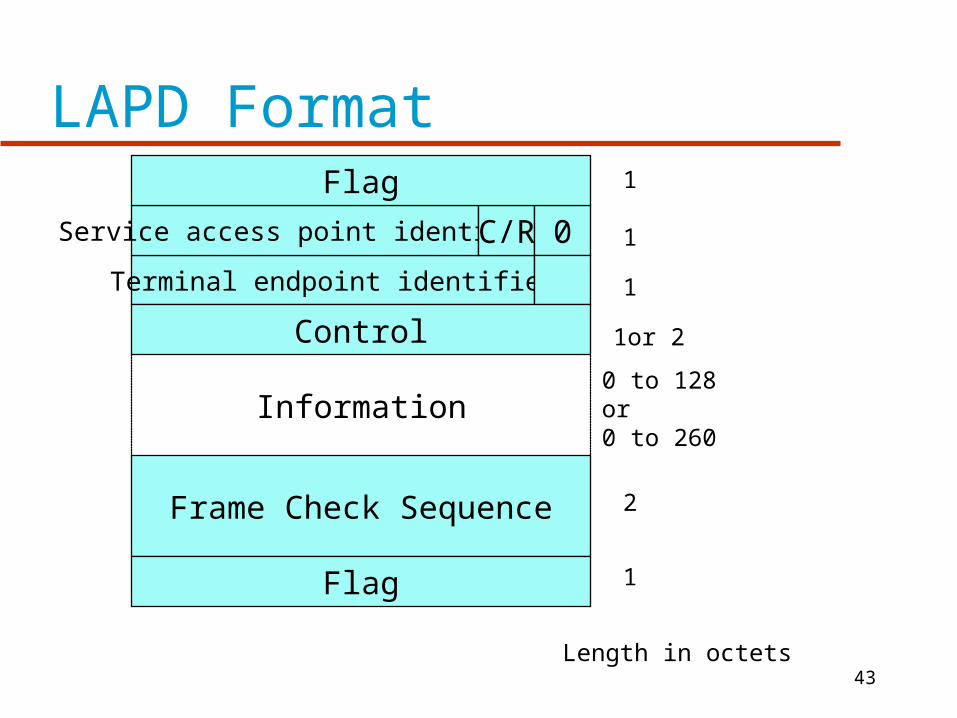
LAPD Format
Terminal endpoint identifier
Service access point identifier C/R 0
Control
Flag
Frame Check Sequence
Flag
Information0 to 128 or0 to 260
1
1
1
1or 2
2
1
Length in octets

44
ISDN Physical Interface
There are no separate control circuits Transmit and receive circuits carry data and
control signals Pseudoternery coding scheme is used for
basic access signals– Voltage level is + or - 750 mV– Data rate is 192 kbps
HDB3 code is used for 2.048 Mbps access B8ZS code is used for 1.544 Mbps access
45
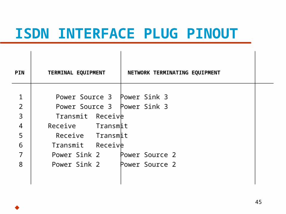
ISDN INTERFACE PLUG PINOUT
PIN TERMINAL EQUIPMENT NETWORK TERMINATING EQUIPMENT
1 Power Source 3 Power Sink 3
2 Power Source 3 Power Sink 3
3 Transmit Receive
4 Receive Transmit
5 Receive Transmit
6 Transmit Receive
7 Power Sink 2 Power Source 2
8 Power Sink 2 Power Source 2
46
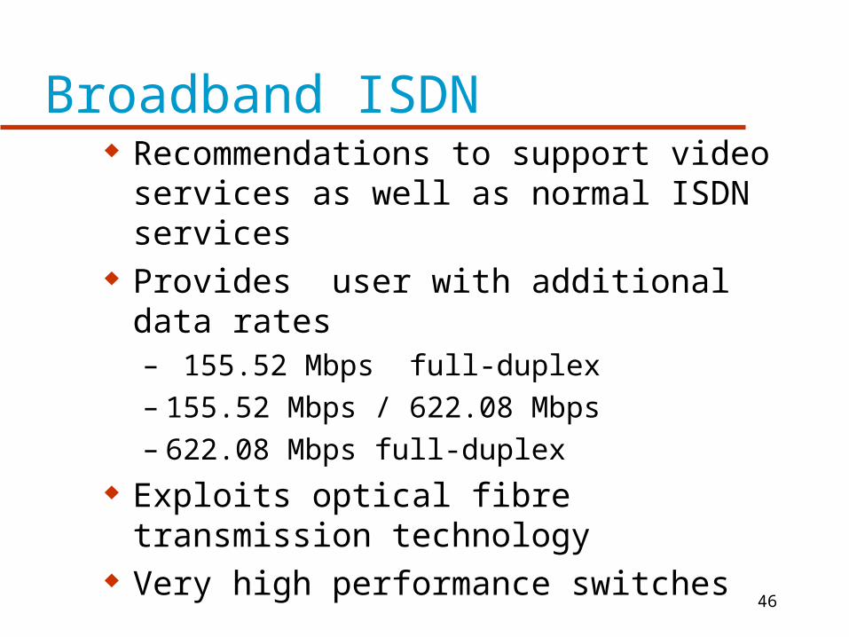
Broadband ISDN Recommendations to support video
services as well as normal ISDN services Provides user with additional data rates
– 155.52 Mbps full-duplex – 155.52 Mbps / 622.08 Mbps– 622.08 Mbps full-duplex
Exploits optical fibre transmission technology
Very high performance switches
47
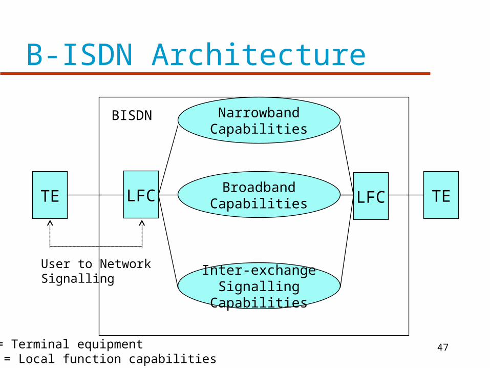
B-ISDN Architecture
TE LFC LFC TE
NarrowbandCapabilities
BroadbandCapabilities
Inter-exchangeSignalling
Capabilities
BISDN
User to NetworkSignalling
TE = Terminal equipmentLFC = Local function capabilities
48
B-ISDN
ATM is specified for Information transfer across the user-network interface
Fixed size 53 octet packet with a 5 octet header
Implies that internal switching will be packet-based
49
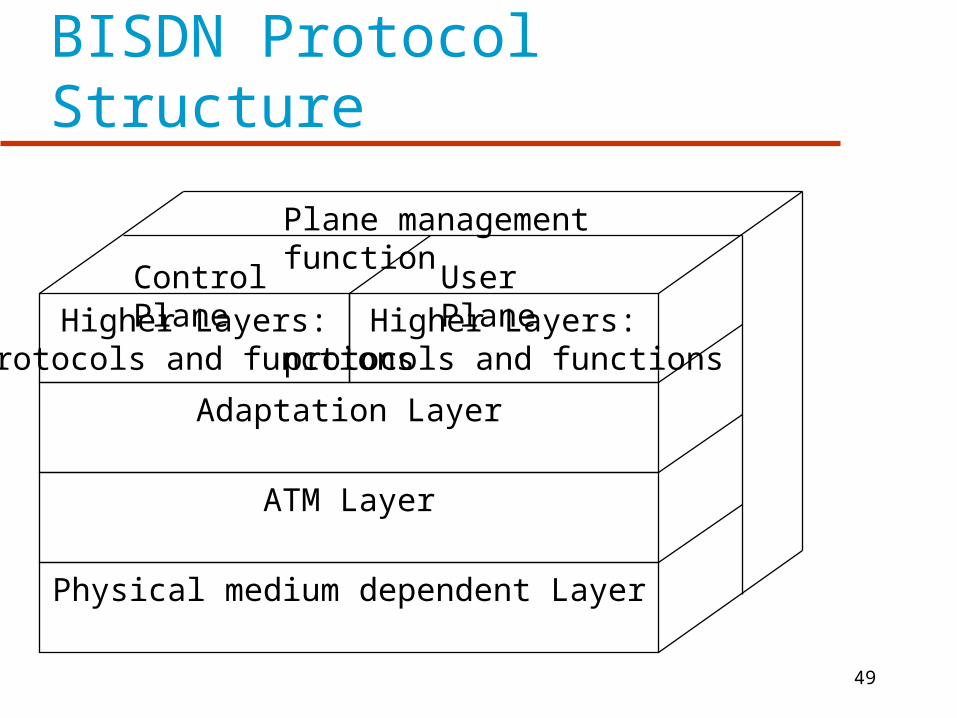
BISDN Protocol Structure
Higher Layers:protocols and functions
Higher Layers:protocols and functions
Adaptation Layer
ATM Layer
Physical medium dependent Layer
Plane management function
Control Plane User Plane