support.blackboxab.sesupport.blackboxab.se/manualer/m/md/md833a-r5.pdf1 fcc statement federal...
TRANSCRIPT

1000 Park Drive • Lawrence, PA 15055-1018 • 724-746-5500 • Fax 724-746-0746
© Copyright 1999. Black Box Corporation. All rights reserved.

1
FCC STATEMENT
FEDERAL COMMUNICATIONS COMMISSION
AND
INDUSTRY CANADA
RADIO FREQUENCY INTERFERENCE STATEMENTS
This equipment generates, uses, and can radiate radio frequency energyand if not installed and used properly, that is, in strict accordance with the manufacturer’s instructions, may cause interference to radiocommunication. It has been tested and found to comply with the limits for a Class A computing device in accordance with the specifications in Subpart J of Part 15 of FCC rules, which are designed to providereasonable protection against such interference when the equipment isoperated in a commercial environment. Operation of this equipment in aresidential area is likely to cause interference, in which case the user at hisown expense will be required to take whatever measures may be necessaryto correct the interference.
Changes or modifications not expressly approved by the party responsiblefor compliance could void the user’s authority to operate the equipment.
This digital apparatus does not exceed the Class A limits for radio noise emissionfrom digital apparatus set out in the Radio Interference Regulation of IndusrtyCanada.
Le présent appareil numérique n’émet pas de bruits radioélectriques dépassant leslimites applicables aux appareils numériques de classe A prescrites dans le Règlementsur le brouillage radioélectrique publié par Industrie Canada.

10
MODEM 32144
1. Specifications
Ringer Equivalence — 0.8 B
Environment — Ambient temperature:32 to 122° F (0 to 50° C); Storagetemperature: -4 to 158° F (-20 to 70° C);Relative humidity: 10 to 95%
Power — 90-132 VAC, 60 Hz
Size — 2.5"H x 10.1"W x 9.7"D (6.4 x 25.7 x24.6 cm)
Weight — 4 lb. (1.8 kg)
Standards — Bell 103, 212, 208, CCITTV.13, V.17, V.22, V.32, V.22 bis, V.25, V.32bis, V.33, V.29, V.32terbo
Protocol — Sync and async
Data Rate — Up to 16.8 and 19.2 Kbps
Operation — Full duplex over 2- or 4-wireleased lines or dialup lines
Connectors — (1) DB25 female, (5) RJ-45female, (1) 5-pin DIN
Configuration — AT Command set orfront-panel
Error Correction/Data Compression —MNP 1-5, V.42, V.42 bis

13
CHAPTER 2: Quick Start
2. Quick StartNote that if you ordered theModem 32144 Card, all you willreceive is the Card itself. It does notcome with the power transformeror cables listed below.
If you ordered the Modem32144, in addition to the modem,the shipping carton shouldcontain—
• A power transformer(with cable attached)
• A two-conductor crossover cable with an eight-pin modularconnector on one end and asix-pin modular connector onthe other end
• A four-conductor cable with twosix-pin modular connectors oneach end and spade lugs on theother end
Two cables are supplied with the modem, but both cables aren’talways needed, depending on theapplication. You will need an EIA RS-232 interface cable (notsupplied) to connect the modem tothe DTE (data terminal equipment,usually a computer). If the modemwill be operated in a manual dialmode, you will also need a standardtelephone set.
This instruction manual applies to the Modem 32144.
All information applies to boththe stand-alone and full-size rack-mount versions of the modem.Specialized low-profile rack-mountversions, designed for use in high-density rack enclosures, aredescribed in Appendix A.
QUICK SETUPS FOR A QUICKSTART
The simplest and fastest wayto set up the modem forimmediate use is to selectone of the factory-presetQuick Setup configurations.For most applications, onceyou have selected the properQuick Setup, the modem willbe ready for operation. Youwill not need to make furtheradjustments.Quick Setupsare explained fully beginningin Section 2.3 , followinginstallation instructions and abrief introduction to the frontpanel display and controls.
2.1 Installation2.1.1 UNPACKING
Keep the original shipping cartonin case you need to return themodem for any reason.

38
MODEM 32144
3. Options: Customizing the ModemSetup
• Summary Setup. This is thefastest way to selectively changemultiple options. All optionsare accessed using just a few of the LCD screens. However,because these screens shownumerical codes with very littleexplanation, Summary Setupis recommended only forexperienced users. SummarySetup is explained in AppendixB.
3.2 Front-Panel OptionsThis chapter describes the standardinstead of selecting options fromthe front panel. An alternatemethod for selecting options fromthe front panel (Summary Setup) is explained in Appendix B.
3.2.1 PUSHBUTTONS AND THE LCDOptions are selected from the frontpanel by pressing the front panelpushbuttons (Fig. 3-1). Thepossible choices for each optionare shown on the liquid-crystaldisplay (LCD).
3.1 Methods for Selecting OptionsThe modem allows you to easilyselect options in order to tailor the modem’s operation to suit aparticular application. Options can be selected in any of thefollowing ways:
• Quick Setup. This is the easiestway to set up the modem.Quick Setup (explained inChapter 2) automatically setsall options according to apreset configuration.
• Front-panel option selection.This is the easiest and mostcommonly used method forselecting individual optionchoices. Typically you wouldselect an overall configurationvia Quick Setup and thenmodify it to suit yourapplication by changingselected options from the frontpanel. Changes are made byaccessing individual optionscreens on the front panel LCDand then making selectionsusing the control pushbuttons.(An alternate way to changeoptions from the front panel isto use the modem’s SummarySetup feature, which isdescribed below.)
MODEM 32144
74
4. General Operation and SpecialFeatures
4.1 Quick ResetFor a reset of the modem, wherebyoption settings are not changed butthe modem is cleared for a newstart and the ROM memory chip ischecked, select RESET from MAINMENU screen 3. The modem willdisplay the power-on screen for afew seconds and then the EIAstatus screen. This feature enablesyou to reset the modem withoutpowering down the unit.
4.2 Storing Phone Numbers4.2.1 USES
The front panel PHONE screenallows you to store a single phonenumber to be used later for—
• Autodialing from the frontpanel or using the Hayes orV.25 bis mode autodialer
• DTR dialing
• Leased-line or dial-line auto-recovery.
This chapter describes thefollowing features and operationalmodes (listed here in the order inwhich they are presented):
• Quick reset
• Phone number storage
• Automatic fallback
• Dumb mode and Bell 208operation
• V.13 operation
• DTR dialing
• Dial Line Auto-Recovery
• Leased Line Auto-Recovery
• Security operation
• Modem-controlled remotecontrol
• Diagnostic interface control
The status screens, which displaydata concerning the operationalstatus of the modem, are discussedin Section 7.6 . Instructions forusing the pushbutton controls andLCD are included in Section 3.2.

97
CHAPTER 5: Hayes Emulation Mode
5. Hayes Emulation Modeto a preset configurationsuitable for typical Hayes modeapplications. To select the 2-wire dial Hayes Quick Setup,access QUICK SETUP screen 1on the LCD and presspushbutton 2.
• DIALER MODE. If you enabledthe Hayes mode autodialerusing the Dialer Mode option,no other options will bechanged. To enable theautodialer this way, selectDIALER from SETUP screen 2.Then select HAYES from theDIALER screen.
5.1.2 COMMAND GUIDELINES
The following guidelines for usingHayes-compatible AT commandsalso provide a summary of thefundamentals of Hayes modeautodialer operation.
NOTEAlthough carriage returnsare not shown in theexamples in this chapter, acarriage return is required atthe end of each commandline.
For easy reference, the followingtables appear consecutively at theend of this chapter:
• Hayes-Compatible Commands(Table 5-1)
• Hayes Mode Result Codes(Table 5-2)
• S Register Functions (Table 5-3)
5.1 Hayes Mode AutodialerWhen the Hayes emulation mode is enabled, the modem emulates aHayes autodialer and functionsmuch like a Hayes modem.Commands are issued from thecomputer keyboard (or otherDTE), and the modem iscompatible with software written to drive a Hayes-style “AT”command set.
5.1.1 ENABLING THE HAYES MODEAUTODIALER
The Hayes mode autodialer can beenabled in either of two ways—byusing the Quick Setup feature or byselecting HAYES from the DIALERscreen:
• QUICK SETUP. If you select 2-Wire Dial (Hayes) by using theQuick Setup feature, the Hayesmode autodialer will beenabled, and all modemoptions will be automatically set

127
CHAPTER 6: V.25 bis Autodialer
6. V.25 bis Autodialer
6.1.1 QUICK SETUP
Three Quick Setup configurationsare available for 2-wire dial V.25 bisoperation. Selecting any of thethree V.25 bis Quick Setups (viaQUICK on SETUP screen 1)enables the V.25 bis autodialer and causes all modem options tobe automatically set to a presetconfiguration. Each V.25 bis QuickSetup is suitable for a typical V.25bis application, depending on theDTE to be used.
To select a 2-wire dial V.25 bisQuick Setup, access QUICK SETUPscreen 2, 3, or 4 (for asynchronous;synchronous, character-oriented; or synchronous, bit-orientedoperation, respectively) on theLCD, and then press pushbutton 2.After selecting the desired V.25 bisQuick Setup configuration, you canreset individual options to suit yourapplication, if desired, as explainedin Chapter 3.
In accordance with the CCITTV.25 bis Recommendation, themodem V.25 bis asynchronousQuick Setup sets the characterlength to 10 bits, including 1 even parity bit. Both V.25 bissynchronous Quick Setups setthe modem for odd parity. (Forsynchronous operation, thecharacter-length option settinghas no effect.)
For international compatibility, the modem can be configured tofunction as a V.25 bis autodialer. In V.25 bis mode, the modem is compliant with CCITTRecommendation V.25 bis, aninternationally recognized standardfor serial automatic call originationand answering.
The V.25 bis autodialer uses thedialing command set defined bythe V.25 bis Recommendation. Itallows you to store and dial phonenumbers from the DTE in bothsynchronous and asynchronousapplications. You can dial numbersdirectly or you can instruct themodem to automatically dial apreviously stored number.
6.1 Enabling the V.25 bis AutodialerThe V.25bis autodialer can beenabled in either of two ways—byusing the Quick Setup feature or by selecting one of the Dialer Modeoptions.

138
MODEM 32144
7. Diagnostics
7.2 Symptoms and Scope of theProblemAs a first step toward isolating theproblem, carefully consider each of the following questions:
• When did the problem begin?
• What is malfunctioning? Try toisolate the component orcomponents of your system thatare malfunctioning.
• Has there been a recent changein the system?
• Has the modem beenreconfigured?
You can quickly find out if themodem has been reconfigured bychecking the checksum shown inthe SUMMARY screen (accessed viaSETUP screen 6) and comparing itwith the checksum displayed whenthe modem was operatingproperly—if you made a note ofthe previous checksum. If thechecksum is different from theoriginal checksum, one or moreoption settings have been changed.If you previously recorded thenumber strings (i.e., optionparameters) displayed in the setupscreens accessed via the SUMMARYscreen, you should be able todetermine which option settingshave been changed (by comparingthe previous and current optionparameters).
The troubleshooting informationin this chapter applies to allmodem applications (all dialupand leased-line modes), unlessspecifically stated otherwise.
For specific test procedures, turnto one of the following sections inthis chapter:
• Section 7.8, Local ModemDiagnostics
• Section 7.9, Remote Diagnostics
7.1 When and Why to Test If you are experiencingcommunications difficulties, theoverall objective in correcting theproblem should be to specificallyisolate the defective component inyour communications system. Thistypically involves three steps:Identifying the symptoms andscope of the problem, performinga physical inspection of all unitsand connections in the system and,finally, conducting diagnostic tests.Very often the diagnostic testingcapabilities of the modem can helpidentify the specific faultycomponent, whether it is themodem, the DTE or telephoneline.
5
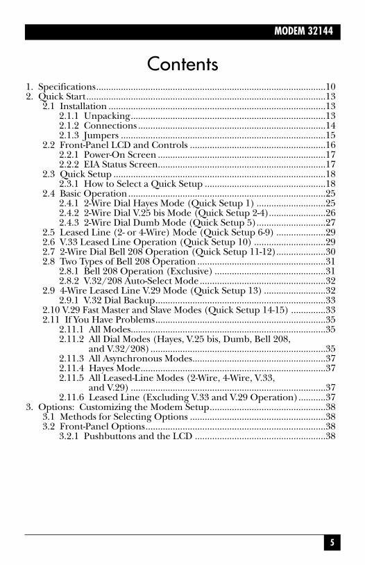
MODEM 32144
Contents1. Specifications.............................................................................................102. Quick Start.................................................................................................13
2.1 Installation ........................................................................................132.1.1 Unpacking...............................................................................132.1.2 Connections ............................................................................142.1.3 Jumpers ...................................................................................15
2.2 Front-Panel LCD and Controls .......................................................162.2.1 Power-On Screen ....................................................................172.2.2 EIA Status Screen....................................................................17
2.3 Quick Setup ......................................................................................182.3.1 How to Select a Quick Setup .................................................18
2.4 Basic Operation................................................................................252.4.1 2-Wire Dial Hayes Mode (Quick Setup 1) ............................252.4.2 2-Wire Dial V.25 bis Mode (Quick Setup 2-4).......................262.4.3 2-Wire Dial Dumb Mode (Quick Setup 5)............................27
2.5 Leased Line (2- or 4-Wire) Mode (Quick Setup 6-9) ....................292.6 V.33 Leased Line Operation (Quick Setup 10) .............................292.7 2-Wire Dial Bell 208 Operation (Quick Setup 11-12)....................302.8 Two Types of Bell 208 Operation ....................................................31
2.8.1 Bell 208 Operation (Exclusive) .............................................312.8.2 V.32/208 Auto-Select Mode...................................................32
2.9 4-Wire Leased Line V.29 Mode (Quick Setup 13) .........................322.9.1 V.32 Dial Backup.....................................................................33
2.10 V.29 Fast Master and Slave Modes (Quick Setup 14-15) ..............332.11 If You Have Problems.....................................................................35
2.11.1 All Modes...............................................................................352.11.2 All Dial Modes (Hayes, V.25 bis, Dumb, Bell 208,
and V.32/208).......................................................................352.11.3 All Asynchronous Modes......................................................372.11.4 Hayes Mode...........................................................................372.11.5 All Leased-Line Modes (2-Wire, 4-Wire, V.33,
and V.29) ...............................................................................372.11.6 Leased Line (Excluding V.33 and V.29 Operation)...........37
3. Options: Customizing the Modem Setup...............................................383.1 Methods for Selecting Options .......................................................383.2 Front-Panel Options.........................................................................38
3.2.1 Pushbuttons and the LCD .....................................................38

156
MODEM 32144
Appendix A: Quick SetupConfigurations
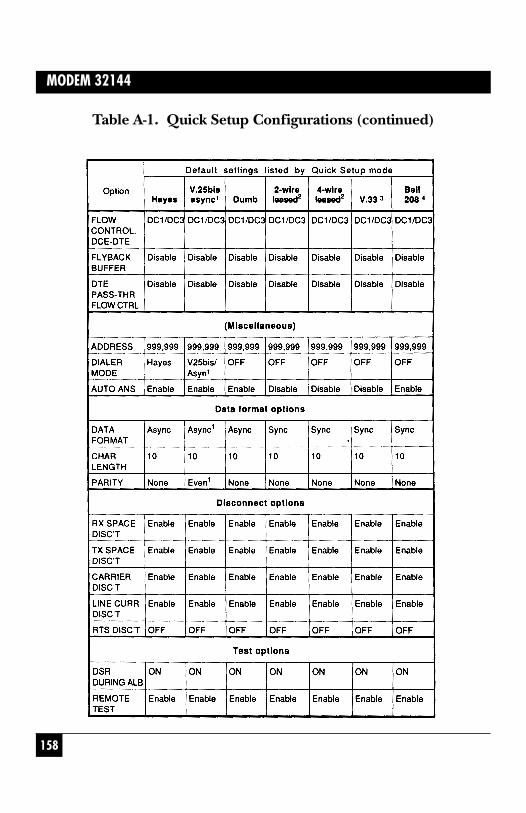
Some options can be selected viaSummary Setup only. Theseoptions are not listed in Table A-1.The factory-default settings forthese options are shown inAppendix B.
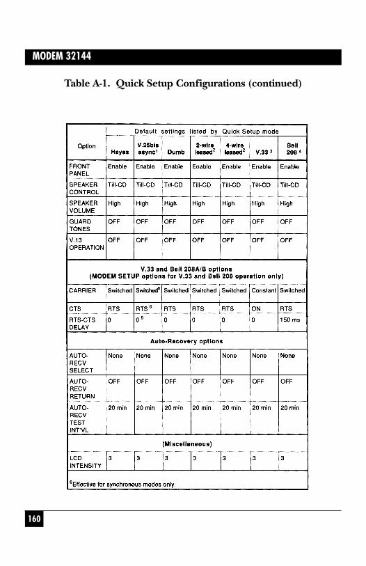
Table A-1 shows the modemconfiguration—i.e., the defaultsetting for each option—for eachof the Quick Setup modes. Whenyou select a Quick Setup, themodem automatically sets alloptions as indicated in the table.The options are listed in the sameorder in which they appear on theLCD flow chart.
Instructions for selecting QuickSetups are included in Chapter 2.

166
MODEM 32144
Appendix B: Summary SetupIf you select AT, the AT
PROFILES screen will be displayed.When you select a Hayes modeconfiguration profile (user profile)from the AT PROFILES screen, theMODEM displays a setup screen forthe selected profile. The selectedprofile is used as the activeconfiguration and is alsodesignated as the default userprofile. Select 0 (pushbutton 1) to select profile 0; select 1(pushbutton 2) to select profile 1.Pushbutton 3, with the ATPROFILES screen displayed,enables you to select the defaultconfiguration profile: By pressingpushbutton 3, you can toggle(switch) between profile 0 orprofile 1 as the default—the effectis the same as issuing the &Ycommand (&Y0 or &Y1).
The SUMMARY screen includes a four-digit checksum value to theright of the word “SUMMARY.”This number will change if any ofthe option settings are changed, soit allows you to determine if any ofthe modem’s option settings havebeen changed, although youcannot determine from thisnumber which options have been changed. After setting up the MODEM, record this numberfor possible later reference.
Summary Setup is an advancedfeature designed to allow exper-ienced users to quickly changeoption settings for any mode. Mostoptions can be viewed from andchanged using a single LCD screen.Summary Setup is the fastest way toselectively change multiple options;however, because the SummarySetup screens show numericalcodes with very little explanation,this method of options selection isrecommended only forexperienced users.
Even though Summary Setupoffers these advantages, it is recom-mended only for experienced usersbecause there is very little guidanceon the LCD screen to indicatewhich option is being changed.
Changes made through SummarySetup modify the active modemconfiguration and are saved tomemory when you exit SummarySetup.
B.1 Summary Setup LCD ScreensSummary Setup (SUMMARY) isaccessed from screen 6 of theSETUP menu. From theSUMMARY screen, choose SETUPSto change options—but for Hayesmode operation (only), choose ATto change options for which thereare associated AT commands(Table B-1).

176
MODEM 32144
Appendix C: Connectors, Adapters,and Jumpers
• LEASED LINE—RJ-11 modularjack, for (6-pin) leased lineconnection
• PHONE—RJ-11 modular jack,for connection to a telephonehandset (optional)
These connectors are illustratedin Chapter 2, which explains howto install the modem and how tomake the connections referred toabove.
The modem includes an edgeconnector for optional rackmounting. When the modem israck mounted, the edge connectorperforms the functions of all theconnectors listed above (and theother connectors are not used).
C.1.1 CONNECTOR PIN ASSIGNMENTS
For users who need to knowconnector pin assignments, thisinformation is provided in FigureC-1 (DIAG, TX DIAL, RX DIAL,LEASED LINE, and PHONEconnectors) and in Table C-1(DTE interface connector).
This appendix provides a detaileddescription of al modemconnectors, including pinassignments. It also includes adescription of the modem jumperfunctions and a diagram that showsyou where to find the jumpers.
C.1 Connectors and AdaptersThe modem includes the followingconnectors (labeled on the rearpanel as indicated below):
• DTE—25-pin (DB25) RS-232/Dfemale cable connector, forconnection to DTE (computeror terminal)
• DIAG—RJ-45 modular jack(diagnostic connector), fordiagnostic port control(optional)
• POWER—Five-pin DINconnector for AC power
• TX DIAL—RJ-45 modular jackfor connection to a dial line
• RX DIAL—(Ignore “RX DIAL”label.) RJ-45 modular jack foralternate leased lineconnection (when an 8-pinconnector is required)
181
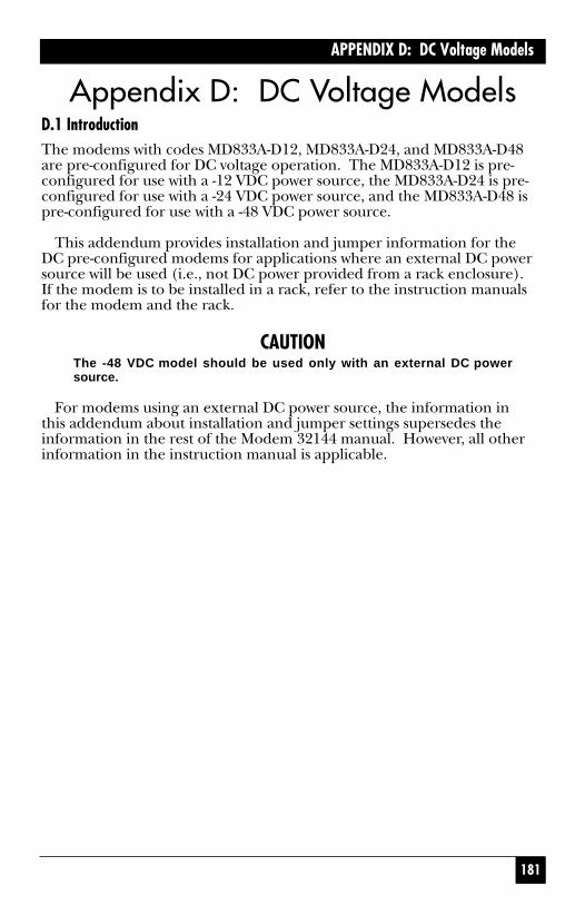
APPENDIX D: DC Voltage Models
Appendix D: DC Voltage ModelsD.1 IntroductionThe modems with codes MD833A-D12, MD833A-D24, and MD833A-D48are pre-configured for DC voltage operation. The MD833A-D12 is pre-configured for use with a -12 VDC power source, the MD833A-D24 is pre-configured for use with a -24 VDC power source, and the MD833A-D48 ispre-configured for use with a -48 VDC power source.
This addendum provides installation and jumper information for the DC pre-configured modems for applications where an external DC powersource will be used (i.e., not DC power provided from a rack enclosure). If the modem is to be installed in a rack, refer to the instruction manualsfor the modem and the rack.
CAUTIONThe -48 VDC model should be used only with an external DC powersource.
For modems using an external DC power source, the information in this addendum about installation and jumper settings supersedes theinformation in the rest of the Modem 32144 manual. However, all otherinformation in the instruction manual is applicable.
DSR during ALBON OFF
REMOTE TESTENABLE DISABLE
CD LEVEL LEASED-26 -33 -43
TEST OPTIONSDSR RMT
CTS to EIANORM RTS TRUE
CD to EIANORM TRUETOGGLE
DSR to EIANORM TRUE XOVER
EIACTS CD DSR
<1>
SETUPTEST EIA MODEM
<4>
EIADTR ALBT RDLT
<2>
DTR from EIANORMAL TRUE
RDL - DTE Ctrl'edENABLE DISABLE
ALB - DTE Ctrl'edENABLE DISABLE
TM to EIANORMAL TRUE
EIATM
<3>
CARRIER DET.LEASED DIAL
LVL
CD LEVEL DIAL-26 -33 -43
MODEM SETUPSCDLVL TXLVL
<1>
TRANSMIT LEVELLEASED DIAL
TX LEVELDEC INC
0 dBm
TX LEVEL (DL)PROG PERMIS
MODEM SETUPSSQ COMEQ TREL
<2>
TRELLIS CODEENABLE DISABLE
SIGNAL QUALITY10^3 10^5
MODEM SETUPSTXCLK T1 RETRN
<3>
TRANSMIT CLOCKINT RX-CLK EXT
AUTO-RETRAINENABLE DISABLE
T1 timer: 0.8secDEC INC
MODEM SETUPSANS/ORG ANSFREQ
<4>
ANSWER TONE2225Hz 2100Hz
ANS/ORG DEFAULTANSWER ORIGINATE
MODEM SETUPSFP SPK SPKVOL
<5>
SPEAKER VOLUMELOW MEDIUM HIGH
SPEAKER CONTROLOFF TILL-CD ON
FPENABLE DISABLE
MODEM SETUPSGUARD V13
<6>
V.13DEC INC
OFF
MODEM SETUPSCARR CTS RTS-CTS
<8>
PASSWORDCHANGE CLEAR
SETUPPHONE AUTO LCDI
<5>
301-555-1234DEC CTRL INC
LCD INTENSITY 5DEC INC
SETUPSUMMARY
<6>
PRI0011214E0 999 99
addr
AT PROFILES0 1 &Y0
DEC SKIP INC
CONFIRM
ATbefImqvwxy0102101341
AT&c
SETUPTYPE LINE SPEED
<1>
LINE TYPE2W-D 2W-LL 4W-LL
V42 CONTROLV42 SEL BUFFER
<1>
BUFFER SELECTENABLE DISABLE
V42 SELECTIONPROTOCOL V42bis
V42MODE CLASS BREAK
V42 MODEOFF MANDAT AUTO
LAPM/MNPDEC INC
SETUPV42 ADDR DIALER
<2>
V42 CONTROLDTE FLOW
<2>
V.42bisENABLE DISABLE
ADDRESS:DEC INC
999,999
PASSTHRU MODEENABLE DISABLE
SETUPANSWER DATA DISC
<3>
DISCONNECTRX TX
<1>
AUTO-ANSWERENABLE DISABLE
RX SPACE DISC'TENABLE DISABLE
TX SPACE DISC'TENABLE DISABLE
DATA FORMATTYPE LENGTH PAR
DATA FORMATSYNC ASYNC
DISCONNECTCARR. CURR. RTS
<2>
CURRENT DISC'TENABLE DISABLE
CARRIER DISC'TENABLE DISABLE
RATEDOWN UP
MAIN MENURESET RATE
<3>MAIN MENUSETUP TEST RMT
<2>MAIN MENUTALK QUICK DIAL
<1>
** **
SPEED TYPEDEC INC
V32
MIN RATE:DEC INC
0-300
MAX RATE:DEC INC
19,200
FLOW CONTROLDTE-DCE DCE-DTE
<1>
DTE SPEED:DEC INC
38,400
MNP CLASSDEC INC
5
FLOW CONTROLPASSTHRU
<2>
DCE-DTENONE CTSon/off
<1> DCE-DTEDC1/DC2 DC1/DC3
<2>
DTE-DCEDEC INC
RTS
RTS DISC'TDEC INC
OFF
PARITY:DEC INC
NONE
CHAR LENGTH9 1110
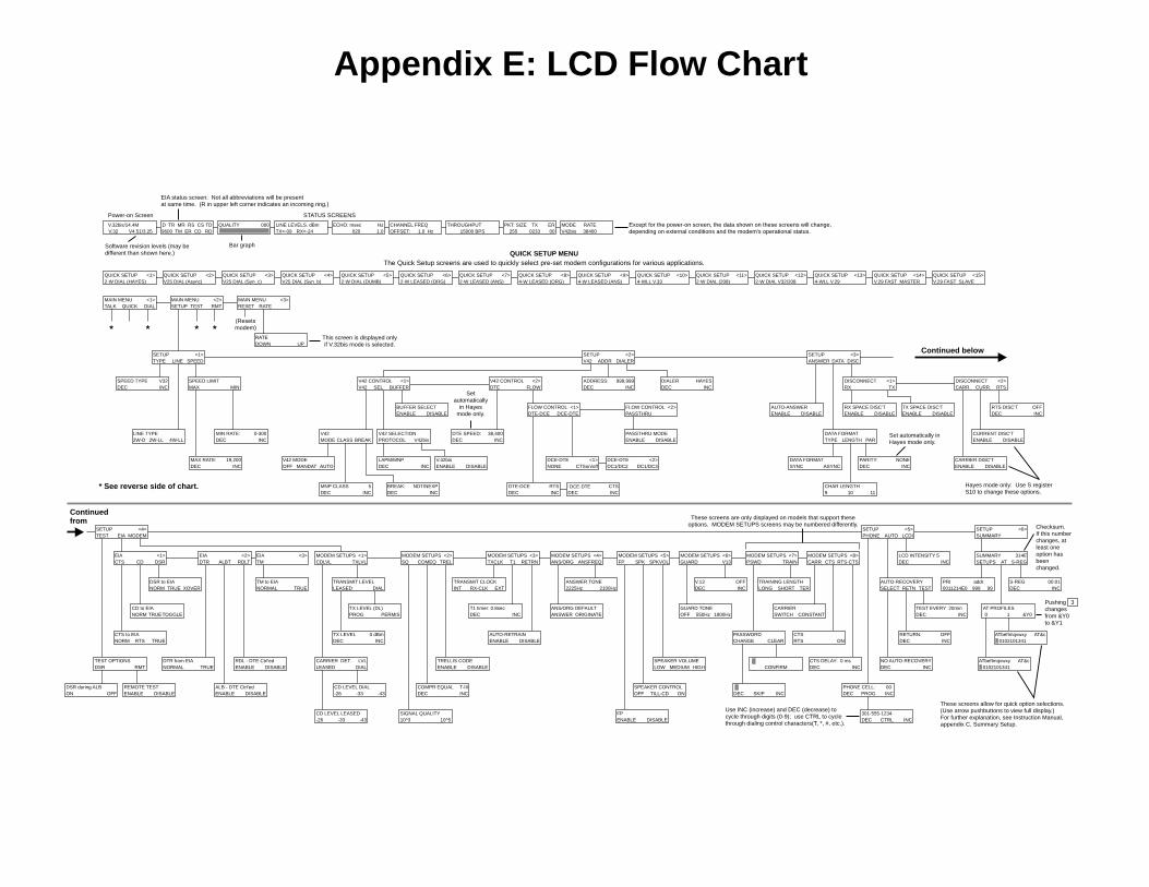
(Resetsmodem)
This screen is displayed onlyif V.32bis mode is selected.
* See reverse side of chart.
Setautomatically
in Hayesmode only.
Set automatically inHayes mode only.
Hayes mode only: Use S registerS10 to change these options.
These screens are only displayed on models that support theseoptions. MODEM SETUPS screens may be numbered differently.
These screens allow for quick option selections.(Use arrow pushbuttons to view full display.)For further explanation, see Instruction Manual,appendix C, Summary Setup.
Use INC (increase) and DEC (decrease) tocycle through digits (0-9); use CTRL to cyclethrough dialing control characters(T, *, #, etc.).
Checksum.If this numberchanges, atleast oneoption hasbeenchanged.
Continued below
Continuedfrom
BREAK:DEC INC
NDT/NEXP
COMPR EQUALDEC INC
T-III
GUARD TONE550Hz 1800HzOFF
PHONE CELL:DEC PROG INC
00
NO AUTO-RECOVERYDEC INC
RETURN:DEC INC
OFF
AUTO-RECOVERYSELECT RETN TEST
TEST EVERY 20minDEC INC
MODEM SETUPSPSWD
<7>TRAIN
CARRIERSWITCH CONSTANT
CTS DELAY: 0 msDEC INC
CTSRTS ON
TRAINING LENGTHLONG SHORT TER
V.32bis/14.4MV.32 V4.51/3.25
D TR MR RS CS9600 TM ER CD RD
TD LINE LEVELS. dBmTX=-09 RX=-24
ECHO: msec020 1.0
Hz CHANNEL FREQOFFSET: 1.0 Hz
THROUGHPUT15000 BPS
QUALITY 000 PKT: SIZE255 0233 00
ERTX MODEV42bis 38400
RATE
Power-on Screen
Software revision levels (may bedifferent than shown here.)
STATUS SCREENS
EIA status screen: Not all abbreviations will be presentat same time. (R in upper left corner indicates an incoming ring.)
Bar graph
Except for the power-on screen, the data shown on these screens will change,depending on external conditions and the modem's operational status.
DTE-DCEDEC INC
CTS
The Quick Setup screens are used to quickly select pre-set modem configurations for various applications.QUICK SETUP MENU
QUICK SETUP2-W DIAL (HAYES)
<1> QUICK SETUPV25 DIAL (Async)
<2> QUICK SETUPV25 DIAL (Syn_c)
<3> QUICK SETUPV25 DIAL (Syn_b)
<4> QUICK SETUP2-W DIAL (DUMB)
<5> QUICK SETUP2-W LEASED (ORG)
<6> QUICK SETUP2-W LEASED (ANS)
<7> QUICK SETUP4-W LEASED (ORG)
<8> QUICK SETUP4-W LEASED (ANS)
<9> QUICK SETUP4-WLL V.33
<10> QUICK SETUP2-W DIAL (208)
<11> QUICK SETUP2-W DIAL V32/208
<12> QUICK SETUP4-WLL V.29
<13> QUICK SETUPV.29 FAST MASTER
<14> QUICK SETUPV.29 FAST SLAVE
<15>
DIALERDEC INC
HAYESSPEED LIMITMAX MIN
SUMMARYSETUPS S-REG
314EAT
S-REGDEC INC
00:01
ATbefImqvwxy0102101341
AT&c
Pushing 3changesfrom &Y0to &Y1
Appendix E: LCD Flow Chart
DCE-DTE

REMOTECONTROL TEST
<1>
CHECKSUMMAIN PUMP
MAIN MENURESET RATE
<3>MAIN MENUSETUP TEST RMT
<2>MAIN MENUTALK QUICK DIAL
<1>
V.32bis/14.4MV.32 V4.51/3.25
D TR MR RS CS9600 TM ER CD RD
TD LINE LEVELS. dBmTX=-09 RX=-24
ECHO: msec020 1.0
Hz CHANNEL FREQOFFSET: 1.0 Hz
THROUGHPUT15000 BPS
QUALITY 000 PKT: SIZE255 0233 00
ERTX MODEV42bis 38400
RATE
* **
Power-on Screen
Software revisionlevels (may bedifferent thanshown here.)
STATUS SCREENS
Bar graph
(Resets modem. LCDreturns to power-on screen,then EIA status screen.)
This screen appears only in theevent of a dial failure. Specificmessage appears on bottom line.
MANUAL-DIALTALK DATA
Displayed only on theALX V.32M and ALXV.32/14.4M.
REMOTE TESTRDL RDLST
REMOT DIGIT LOOPON OFF
RDL SELFTESTON OFF
REMOTECTRL ADDR/C ADDR
<2>
LOCAL TESTALB ALBST ST/E
<1>
ANALOG LOOPBACKON OFF
ANALOG SELFTESTON OFF
SELFTEST w/ERRORON OFF
LOCAL TESTDLB ALBX ALXST
<2>
DIGITAL LOOPBACKON OFF
ANALOG LOOP (EXT)ON OFF
ANALOG ST (EXT)ON OFF
If SLOT/C is selectedfrom REMOTE screen2 (above), the top linehere will read SLOTNUMBER: 01.
Data displayed here is for use by servicing personnel.Screens show software revision levels and variouschecksums for both the main processor and the datapump (transmitter, T, and receiver, R). It is unlikely thatthe numbers on your unit will match those shownhere—this is normal.
(Accessed by pressing 1from EIA status screen.)
Note: When a test is activated, the EIA status screen will be displayed.
Use pushbutton 2 to togglebetween ADDR/C and SLOT/C.
MAINV3.02.02
m1_mt9bf219BB
PumpV2.03.1 U52 280C
U51 C5E8
DIAL FAILURENO DTR
DIAL CELL:DEC DIAL INC
e00
ADDRESS :DEC INC
999,999
AUTO-DIALDIAL HANGUPCELL
Displayed on the Modem 32144.

182
MODEM 32144
D.2 InstallationUse the supplied cable to attachthe modem to the external DCpower source, as shown in Fig. D-1.
Fig. D-1. Attaching the supplied cable to the DC power source.
DIAGTX
DIALLEASED
LINE PHONEPOWER
Black
Red
Pos. (+)source
Neg. (-)source
Refer also to Section 2.1,Installation but ignore informationabout the AC power transformercable.
183
APPENDIX D: DC Voltage Models
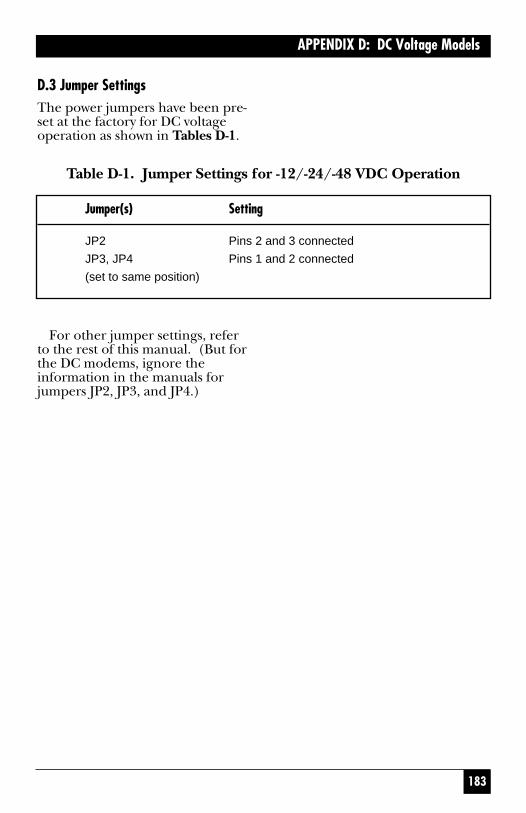
D.3 Jumper SettingsThe power jumpers have been pre-set at the factory for DC voltageoperation as shown in Tables D-1.
Table D-1. Jumper Settings for -12/-24/-48 VDC Operation
Jumper(s) Setting
JP2 Pins 2 and 3 connected
JP3, JP4 Pins 1 and 2 connected
(set to same position)
For other jumper settings, referto the rest of this manual. (But forthe DC modems, ignore theinformation in the manuals forjumpers JP2, JP3, and JP4.)

184
MODEM 32144
D.4 Jumper LocationsThe jumper locations are shownbelow for your information;however, since the jumper settingsare pre-configured, you should nothave to change them.
Fig. D-2. Partial view of modem circuit board, showing jumperlocations.
JP2
JP1
JP6JP5
JP8
JP7
JP3
JP4
For each jumper, pin 1 isidentified by a “1” on the modemcircuit board. (The JP2 pin 1 labelmay be difficult to read; JP2 pin 1 is the pin closest to the edgeconnector.)

NOTES

NOTES

NOTES

NOTES

NOTES

NOTES

177
APPENDIX C: Connectors, Adapters, and Jumpers
Figure C-1. Connector Pin Assignments.
All connectors are shown as viewed from the back of the modem. Pins not included in the listings above are not used.
POWERDIAG PHONE
LEASEDLINE
RXDIAL
TXDIALDTE
REAR PANEL
DB25
RJ-45
1 2 3 4 5 6 7 8
Dial Line Connector
Pin345678
FunctionA/MIRingTipA1/MICPCPR
RJ-11
1 2 3 4 5 6
Phone Connector
Pin2345
FunctionARingTipA1
RJ-11
1 2 3 4 5 6
Leased LineConnector
Pin2345
FunctionRXLLTXLLTXLLRXLL
RJ-45
1 2 3 4 5 6 7 8
Pin1278
FunctionTXLLTXLLRXLLRXLL
Alternate LeasedLine Connector
(Ignore “RX DIAL” Label)
Diagnostic Connector
Pin Function1 Constellation Y Output2 Constellation X Output4 Ground (for transmit and
receive data and constellation)5 Receive Data (output from
modem)6 Transmit Data (input to modem)
RJ-45
1 2 3 4 5 6 7 8
DIAG port always appears to asystem as a DCE port.

178
MODEM 32144
Table C-1. Pin Assignments—DB25 TIA/EIA Interface Connector
Pin Function Designation SourceEIA ITU-T LCD
1 Frame ground—not connected AA 101
2 Transmit (send) data (TD) BA 103 TD DTE
3 Received data (RD) BB 104 RD Modem
4 Request to send (RTS) CA 105 RS DTE
5 Clear to Send (CTS) CB 106 CS Modem
6 Data Set (modem) Ready (DSR) CC 107 MR Modem
7 Signal ground (SG) AB 102 Ground
8 Carrier detect (CD) CF 109 CD Modem
9 Testing voltage, +10V +P Modem
10 Testing voltage, -10V -P Modem
15 Transmit clock (TC) DB 114 Modem
17 Receive clock (RC) DD 115 Modem
18 Analog loopback (ALB) control1 CN DTE
20 Data terminal ready (DTR) CD 108/2 TR DTE
21 Remote digital loopback (RDL) CN DTEcontrol1
22 Ring indicator (RI) CE 125 R Modem
24 External transmit clock (XTC) DA 113 DTE
25 Test mode indicator (TM)2 CN TM Modem
1+ voltage activates indicated loopback test (but only if ALB-DTE Ctrl’ed or RDL-DTE Ctrl’ed option is enabled);—voltage disables test.2Alternately, pin 25 may be used for analog loopback (ALB) control.

179
APPENDIX C: Connectors, Adapters, and Jumpers
C.2 Jumpers
WARNINGJumpers should be switchedonly by qualified servicepersonnel.
For most applications, there is noneed to reset the modem’s internaljumper switches. However, ajumper switch will have to be resetif you need to—
Connect frame ground to signalground, Switch from A/A1 controlto MI/MIC control, Strap themodem for use in a DC rackenclosure, or Change the functionof EIA interface pin 25.
If you need to reset a jumperswitch, refer to the following pageto determine the jumper thatshould be switched, where it islocated, and how it should be set.The jumpers are numbered on thecircuit board; for example, JP4 isjumper 4. To access the jumpers,unscrew the four screws on thebottom of the modem and carefullylift off the cover.
WARNINGImproper setting of AC andDC power jumpers couldresult in serious damage tothe modem.

180
MODEM 32144
Table C-2. Jumper Switch Functions
Jumper(s) Position1 Function
JP1 FG Frame and signal ground connected
Alternate position Not connected
(no legend)
JP2, JP3 A1 A/A1 control
(Set to same MI MI/MIC control
position)
JP4, JP5, AC AC power
JP8 Alternate position DC power (for Telco 48 VDC battery)
(Set to same
position)
JP7 TM (output) Pin 25 used as test mode indicator
AL (input) Pin 25 used for analog loopback
1As indicated by legend printed on modem circuit board.
Factory settings are shown in boldface.

167
APPENDIX B: Summary Setup
B.2 Changing Options via SummarySetupThe appearance of the three setupscreens selected via SETUPS andAT (profile 0 or 1) is essentially the same: Brief descriptiveinformation on the top line and a long string of numbers on thebottom line. The numbers arebroken down into groups, witheach group representing a categoryof options (dial line options, EIAinterface options, etc.).
Each digit position represents anoption, and the number in eachdigit position indicates the currentoption setting (parameter). Tochange an option setting, use thefront panel pushbuttons to changethe parameter (number), asexplained in the following section.
The diagrams on the followingpages show—
• Which options are included ineach option group
• Which option is indicated byeach digit position within thegroup
• The possible parameters foreach option
B.2.1 SUMMARY SETUP PUSHBUTTONFUNCTIONS
The three Summary Setup screensare different from all other modemscreens in that you can scroll acrossthe string of numbers; also, thepushbutton functions are different. For the three Summary Setupscreens only, the modempushbuttons function as follows:
• Pushbutton 1 moves the cursorto the left. Pushbutton 3 movesthe cursor to the right. If thecursor is at the end of thescreen, the screen will scrollone character at a time.
• Pushbutton 2 increments theblinking value (i.e., theparameter, or current optionsetting). The value will cyclethrough the highest possibleparameter value and then backto 0 or 1.
• The right arrow button movesthe screen to the beginning ofthe next group of options tothe right. The left arrow buttonmoves the screen to thebeginning of the next group ofoptions to the left. Groups ofoptions are separated by blankspaces on the LCD.
000
MODEM 32144
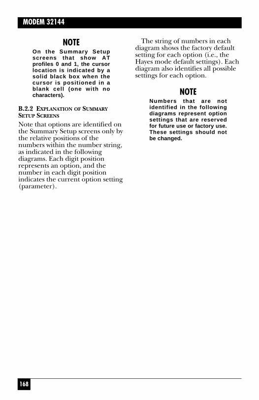
NOTEOn the Summary Setupscreens that show ATprofiles 0 and 1, the cursorlocation is indicated by asolid black box when thecursor is positioned in ablank cell (one with nocharacters).
B.2.2 EXPLANATION OF SUMMARYSETUP SCREENS
Note that options are identified onthe Summary Setup screens only bythe relative positions of thenumbers within the number string,as indicated in the followingdiagrams. Each digit positionrepresents an option, and thenumber in each digit positionindicates the current option setting(parameter).
The string of numbers in eachdiagram shows the factory defaultsetting for each option (i.e., theHayes mode default settings). Eachdiagram also identifies all possiblesettings for each option.
NOTENumbers that are notidentified in the followingdiagrams represent optionsettings that are reservedfor future use or factory use.These settings should notbe changed.
168
169
APPENDIX B: Summary Setup
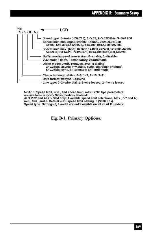
Fig. B-1. Primary Options.
Speed type: 0=Auto (V.32/208), 1=V.33, 2=V.32/32bis, 3=Bell 208Speed limit, min. (bps): 0=9600, 1=4800, 2=2400,3=1200 4=600, 5=0-300,6=1200/75,7=14,400, 8=12,000, 9=7200Speed limit, max. (bps): 0=9600,1=4800,2=2400,3=12000,4=600, 5=0-300, 6=EIA-23, 7=1200/75, 8=14,400,9=12,000,A=7200Buffer mode/speed conversion: 0=enable, 1=disableV.42 mode : 0=off, 1=mandatory, 2=automaticDialer mode: 0=off, 1=Hayes, 2=DTR dialing; 3=V.25bis, async; 4=V.25bis, sync, character-oriented; 5=V.25bis, sync, bit-oriented; 6=Penril mode
Character length (bits): 0=8, 1=9, 2=10, 3=11Data format: 0=sync, 1=async
258021210PRI
Line type: 0=2--wire dial, 1=2-wire leased, 2=4-wire leased
NOTES: Speed limit, min., and speed limit, max.: 7200 bps parametersare available only if V.32bis mode is enabled.ALX V.32 and ALX V.32M only: Available speed limit selections: Max., 0-7 and A;min., 0=6 and 9. Default max. speed limit setting: 0 (9600 bps).Speed type: Settings 0, 1 and 3 are not available on all all ALX models.
LCD
170
MODEM 32144
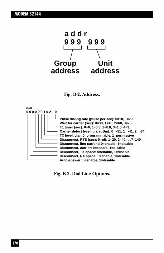
Fig. B-2. Address.
9 9 9
Groupaddress
9 9 9
Unitaddress
a d d r
dial0 0 0 0 0 0 1 0 2 1 0
Pulse dialing rate (pulse per sec): 0=10, 1=20Wait for carrier (sec): 0=30, 1=45, 2=60, 3=75T1 timer (sec): 0=0, 1=0.3, 2=0.8, 3=1.6, 4=3.Carrier detect level, dial (dBm): 0= -51, 1= -41, 2= -34TX level, dial: 0=programmable, 1=permissiveDisconnect, RTS (sec): 0=off, 1=20, 2=40 . . .7=140Disconnect, line current: 0=enable, 1=disableDisconnect, carrier: 0=enable, 1=disableDisconnect, TX space: 0=enable, 1=disableDisconnect, RX space: 0=enable, 1=disableAuto-answer: 0=enable, 1=disable
Fig. B-3. Dial Line Options.
171
APPENDIX B: Summary Setup
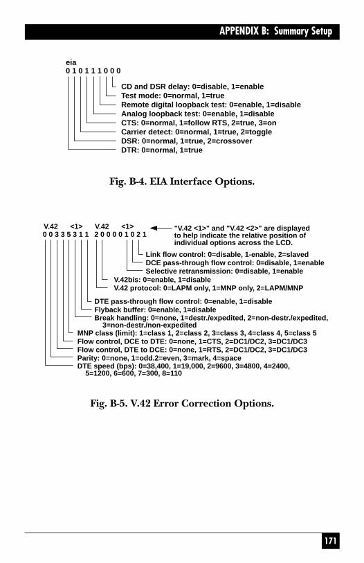
Fig. B-4. EIA Interface Options.
Fig. B-5. V.42 Error Correction Options.
eia0 1 0 1 1 1 0 0 0
CD and DSR delay: 0=disable, 1=enableTest mode: 0=normal, 1=trueRemote digital loopback test: 0=enable, 1=disableAnalog loopback test: 0=enable, 1=disableCTS: 0=normal, 1=follow RTS, 2=true, 3=onCarrier detect: 0=normal, 1=true, 2=toggleDSR: 0=normal, 1=true, 2=crossoverDTR: 0=normal, 1=true
MNP class (limit): 1=class 1, 2=class 2, 3=class 3, 4=class 4, 5=class 5Flow control, DCE to DTE: 0=none, 1=CTS, 2=DC1/DC2, 3=DC1/DC3Flow control, DTE to DCE: 0=none, 1=RTS, 2=DC1/DC2, 3=DC1/DC3Parity: 0=none, 1=odd.2=even, 3=mark, 4=space
DTE pass-through flow control: 0=enable, 1=disableFlyback buffer: 0=enable, 1=disable
V.42bis: 0=enable, 1=disableV.42 protocol: 0=LAPM only, 1=MNP only, 2=LAPM/MNP
Link flow control: 0=disable, 1-enable, 2=slavedDCE pass-through flow control: 0=disable, 1=enableSelective retransmission: 0=disable, 1=enable
DTE speed (bps): 0=38,400, 1=19,000, 2=9600, 3=4800, 4=2400, 5=1200, 6=600, 7=300, 8=110
Break handling: 0=none, 1=destr./expedited, 2=non-destr./expedited, 3=non-destr./non-expedited
"V.42 <1>" and "V.42 <2>" are displayedto help indicate the relative position ofindividual options across the LCD.
2 0 0 0 0 1 0 2 10 0 3 3 5 3 1 1V.42 <1> V.42 <1>

172
MODEM 32144
Fig. B-6. Leased Line Options.
Carrier detect level, leased (dBm): 0= -43, 1= -33, 2=-26TX level, leased (dBm): 0=0, 1= -1... 9= -9, A= -10 ... F= -15TX clocking: 0=internal, 1=received clocking, 2=externalAnswer/originate: 0=answer, 1=originate
Auto-recovery test interval (min): 0=10, 2=40, 3=60Auto-recovery return (sec): 0=off, 1=10, 2=40, 3=60, 4=120Auto-recovery select: 0=none, 1=dial if bad 1 min ... 4=dial if bad 4 min, 5=dial if bad 30 sec 96-8 not used), 9=manual recovery
L. L.1 0 0 2 0 0 1 0

173
APPENDIX B: Summary Setup
Fig. B-7. Data Pump 1 Options.
Trellis coding: 0=enable, 1=disableAnswer tone: 0=2225 Hz, 1=2100 HzGuard tone: 0=550 Hz, 1=1800 Hz, 2=offAuto-retrain: 0=enable, 1=disableSignal quality level (error/bits): 0=1 in 10^3, 1=1 in 10^5Compromise equalizer type: 0=I, 1=II< 2=III, 3=IV, 4=off
Phase reversal in answer tone: 0=enable, 1=disableAuxiliary channel: 0=enable, 1=disableSpeed fallback: 0=enable, 1=disable
"pump1," "pump2," and "pump3" are displayed to help indicatethe relative positions of individual options across the LCD.The "pump2", and "pump3" options are identified below.pump 1
2 0 0 2 1 0 3 0 0 0 1
12
34
56 Rate renegotiation (RRP): 0=disable, 1=enable
89
10
12
34
56
78
pump 20 0 0 0 0 1 1 0 0 0
pump 30 0 0 0 0 1 0 0
Turnaround delay: 0=disable, 1=enableSatellite delay: 0=disable, 1=enableRTS-to-CTS delay (ms): 0=none, 1=15, 2=50, 3=150CTS: 0=always ON, 1=follow RTSCarrier type: 0=switched, 1=constant
Forward rate renegotiation: 0=disable, 1=enableRetrain threshold (error/bits): 0=10^4, 1=10^6208 phase detection: 0=normal, 1=compensated
V.26 scrambler: 0=disable, 1=enableAnti-streaming timer: 0=disable, 1=enableV.26 dibit encoding: 0=alternative A, 1=alt. BEcho protection tone: 0=disable, 1=short, 2=long
V.27bis 2400-bps alternatives: 0=alternative i, 1=alt. iiV.3x/208 auto-detect mode: 0=disable, 1=enableV.22bis S1 duration (ms): 0=100, 1=150Fast connect 103 mode: 0=disable, 1=enable
Fig. B-8. Data Pump 2 and 3 Options.
174
MODEM 32144
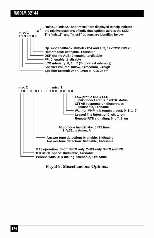
Fig. B-9. Miscellaneous Options.
Op. mode fallback: 0=Bell 212A and 103, 1=V.22/V.21/V.23Remote test: 0=enable, 1=disableDSR during ALB: 0=enable, 1=disableFP: 0=enable, 1=disableLCD intensity: 0, 1... 7 (7=greatest intensity)Speaker volume: 0=low, 1=medium, 2=highSpeaker control: 0=on, 1=on till CD, 2=off
misc 1
"misc1," "misc2," and "misc3" are displayed to help indicatethe relative positions of individual options across the LCD.The "misc2", and "misc3" options are identified below.1 2 3 0 0 0 0
Low-profile DIAG LED: 0=Connect status, 1=DTR statusCFI AB response on disconnect: 0=disable, 1=enable
Multimode handshake: 0=T1 timer, 1=V.32bis Annex A
misc 2 misc 30 1 0 0 0 0 0 F F F F 1 0 0 0 0 0 0 0 0
Wait for MNP link request (sec): 0=3, 1=7Leased line interrupt:0=off, 1=onRemote RTS signaling: 0=off, 1=on
Answer tone detection: 0=enable, 1=disableAnswer tone detection: 0=enable, 1=disable
V.13 operation: 0=off, 1=TX only, 2=RX only, 3=TX and RXDTE=DCE speed: 0=disable, 1=enablePenn/V.25bis DTR dialing: 0=enable, 1=disable

175
APPENDIX B: Summary Setup
Fig. B-10. Hayes Mode Options—For Each AT Profile.
AT commands
AT & commands
S registers
AT/ commands(most are forV.42 options)
ATbeflmqvxy110210141
AT&cdgjlpqrsx1200000000
s00 s18 s25 s26001 000 005
AT/abcdfkmnpq t vx315013032330011
Flow control, DCE
Flow control, DTE
Load inactivity timer

157
APPENDIX A: Quick Setup Configurations
Table A-1. Quick Setup Configurations
158
MODEM 32144
Table A-1. Quick Setup Configurations (continued)

159
APPENDIX A: Quick Setup Configurations
Table A-1. Quick Setup Configurations (continued)
160
MODEM 32144
Table A-1. Quick Setup Configurations (continued)

161
APPENDIX A: Quick Setup Configurations
Table A-2. Additional Quick Setup Configurations
Default settings listed by Quick Setup mode
Option Bell 4-wire V.29 V.292081 leased fast fast
V.29 master slaveCommunication Standard option
STD 208 V.29 V.29 V.29
Speed Limit option, V.32, V.32M, V.32/14.4, V.32/14.4M, V.32/19.2, V.32/19.2M
MAX DCE 4800 9600 9600 9600RATE
MIN DCE 4800 4800 4800 4800
Default settings listed by Quick Setup mode
Option Bell 2081 4-wire V.29 fast V.29 fastleased V.29 master slave
BUFFER Disable Disable Disable Disable
DTE SPEED 38.4 Kbps 38.4 Kbps 38.4 Kbps 38.4 Kbps
FLOW RTS RTS RTS RTSCONTROLDTE-DCE
FLOW CTS CTS CTS CTSCONTROLDCE-DTE
DTE Disable Disable Disable DisablePASS-THRUFLOW CTRL

162
MODEM 32144
Table A-2 (continued). Additional Quick Setup Configurations
(Miscellaneous)
ADDRESS2 999,999 999,999 999,999 999,999
DIALER OFF OFF OFF OFFMODE
AUTO Enable Enable Disable DisableANSWER
Data Format Options
DATA TYPE Sync Sync Sync Sync
CHAR 10 10 10 10LENGTH
PARITY None None None None
Disconnect Options
RX SPACE Disable Disable Disable DisableDISC’T
TX SPACE Disable Disable Disable DisableDISC’T
CARRIER Enable Enable Enable EnableDISC’T
LINE CURR Enable Enable Enable EnableDISC’T
RTS DISC’T OFF OFF OFF OFF
2Quick Setup does not change the address to the default address, but a factoryreset does.
163
APPENDIX A: Quick Setup Configurations
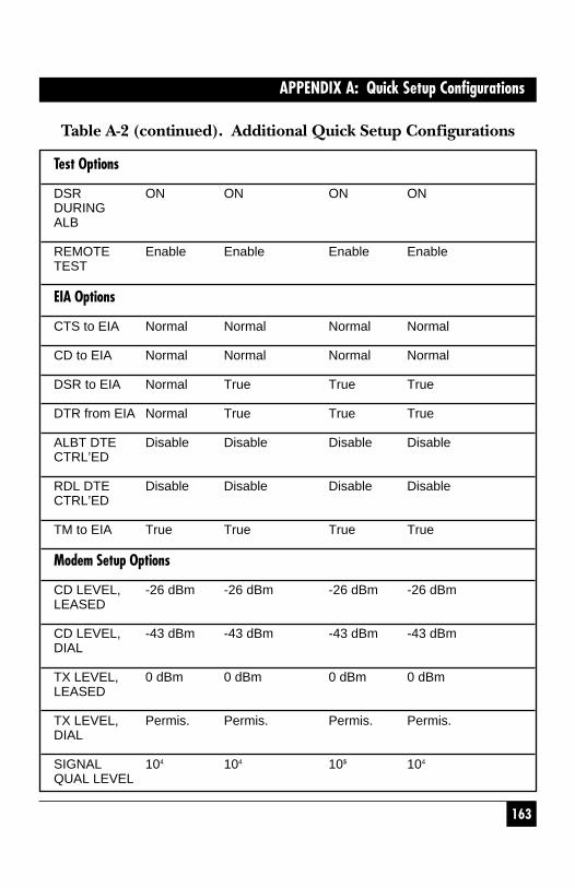
Table A-2 (continued). Additional Quick Setup Configurations
Test Options
DSR ON ON ON ONDURINGALB
REMOTE Enable Enable Enable EnableTEST
EIA Options
CTS to EIA Normal Normal Normal Normal
CD to EIA Normal Normal Normal Normal
DSR to EIA Normal True True True
DTR from EIA Normal True True True
ALBT DTE Disable Disable Disable DisableCTRL’ED
RDL DTE Disable Disable Disable DisableCTRL’ED
TM to EIA True True True True
Modem Setup Options
CD LEVEL, -26 dBm -26 dBm -26 dBm -26 dBmLEASED
CD LEVEL, -43 dBm -43 dBm -43 dBm -43 dBmDIAL
TX LEVEL, 0 dBm 0 dBm 0 dBm 0 dBmLEASED
TX LEVEL, Permis. Permis. Permis. Permis.DIAL
SIGNAL 104 104 10$ 104
QUAL LEVEL
164
MODEM 32144
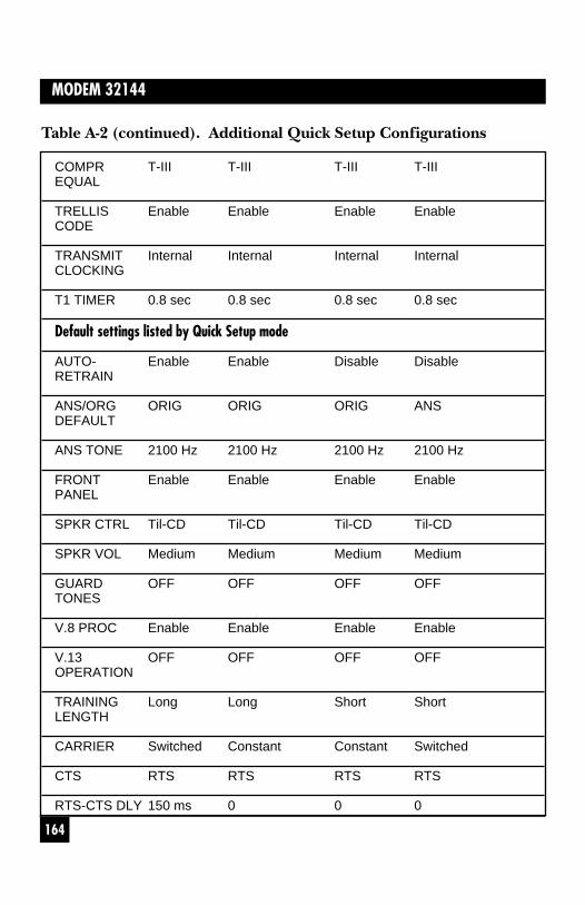
Table A-2 (continued). Additional Quick Setup Configurations
COMPR T-III T-III T-III T-IIIEQUAL
TRELLIS Enable Enable Enable EnableCODE
TRANSMIT Internal Internal Internal InternalCLOCKING
T1 TIMER 0.8 sec 0.8 sec 0.8 sec 0.8 sec
Default settings listed by Quick Setup mode
AUTO- Enable Enable Disable DisableRETRAIN
ANS/ORG ORIG ORIG ORIG ANSDEFAULT
ANS TONE 2100 Hz 2100 Hz 2100 Hz 2100 Hz
FRONT Enable Enable Enable EnablePANEL
SPKR CTRL Til-CD Til-CD Til-CD Til-CD
SPKR VOL Medium Medium Medium Medium
GUARD OFF OFF OFF OFFTONES
V.8 PROC Enable Enable Enable Enable
V.13 OFF OFF OFF OFFOPERATION
TRAINING Long Long Short ShortLENGTH
CARRIER Switched Constant Constant Switched
CTS RTS RTS RTS RTS
RTS-CTS DLY 150 ms 0 0 0
165
APPENDIX A: Quick Setup Configurations
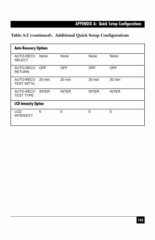
Table A-2 (continued). Additional Quick Setup Configurations
Auto-Recovery Options
AUTO-RECV None None None NoneSELECT
AUTO-RECV OFF OFF OFF OFFRETURN
AUTO-RECV 20 min 20 min 20 min 20 minTEST INT’VL
AUTO-RECV INTER INTER INTER INTERTEST TYPE
LCD Intensity Option
LCD 5 5 5 5INTENSITY

166
MODEM 32144
Do not Make PDF of this page
6
MODEM 32144
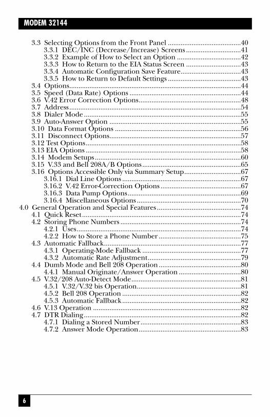
3.3 Selecting Options from the Front Panel ........................................403.3.1 DEC/INC (Decrease/Increase) Screens ..............................413.3.2 Example of How to Select an Option ...................................423.3.3 How to Return to the EIA Status Screen ..............................433.3.4 Automatic Configuration Save Feature.................................433.3.5 How to Return to Default Settings ........................................43
3.4 Options..............................................................................................443.5 Speed (Data Rate) Options .............................................................443.6 V.42 Error Correction Options........................................................483.7 Address..............................................................................................543.8 Dialer Mode ......................................................................................553.9 Auto-Answer Option ........................................................................553.10 Data Format Options .....................................................................563.11 Disconnect Options........................................................................573.12 Test Options.....................................................................................583.13 EIA Options .....................................................................................583.14 Modem Setups................................................................................603.15 V.33 and Bell 208A/B Options......................................................653.16 Options Accessible Only via Summary Setup...............................67
3.16.1 Dial Line Options .................................................................673.16.2 V.42 Error-Correction Options ............................................673.16.3 Data Pump Options..............................................................693.16.4 Miscellaneous Options .........................................................70
4.0 General Operation and Special Features ..............................................744.1 Quick Reset.......................................................................................744.2 Storing Phone Numbers ..................................................................74
4.2.1 Uses..........................................................................................744.2.2 How to Store a Phone Number .............................................75
4.3 Automatic Fallback...........................................................................774.3.1 Operating-Mode Fallback ......................................................774.3.2 Automatic Rate Adjustment...................................................79
4.4 Dumb Mode and Bell 208 Operation.............................................804.4.1 Manual Originate/Answer Operation ..................................80
4.5 V.32/208 Auto-Detect Mode............................................................814.5.1 V.32/V.32 bis Operation.........................................................814.5.2 Bell 208 Operation .................................................................824.5.3 Automatic Fallback.................................................................82
4.6 V.13 Operation .................................................................................824.7 DTR Dialing......................................................................................82
4.7.1 Dialing a Stored Number.......................................................834.7.2 Answer Mode Operation........................................................83
7
MODEM 32144
4.8 Dial Line Auto-Recovery ..................................................................834.8.1 Setting Up the Modem for Dial Line Auto-
Recovery ..................................................................................834.8.2 Recovery Procedure ...............................................................84
4.9 Leased Line Auto-Recovery .............................................................844.9.1 Autodial Backup .....................................................................854.9.2 Exit from Leased Line Auto-Recovery ..................................854.9.3 Leased-Line Auto-Recovery Options.....................................86
4.10 Modem Security Operation...........................................................874.11 Automatic Password Protection (APP)..........................................874.12 Configuring Modems for APP.......................................................89
4.12.1 APP Without Callback ..........................................................894.12.2 APP With Callback................................................................894.12.3 Password Screens ..................................................................894.12.4 Valid Password Characters ...................................................904.12.5 APP with Callback: Storing the Password with
Callback Number..................................................................914.13 Disabling APP .................................................................................91
4.13.1 Temporarily Disabling APP..................................................914.13.2 Clearing the Password ..........................................................92
4.14 Manual-Response Password Protection (MPP)............................924.15 Commands for Enabling MPP.......................................................934.16 How to Use Password Commands.................................................94
5. Hayes Emulation Mode ............................................................................975.1 Hayes Mode Autodialer ...................................................................97
5.1.1 Enabling the Hayes Mode Autodialer...................................975.1.2 Command Guidelines ............................................................97
5.2 Result Codes .....................................................................................995.3 Transmission Speed........................................................................1005.4 Hayes Compatible Commands......................................................1015.5 S Registers .......................................................................................107
5.5.1 Reading and Setting Registers .............................................1075.5.2 S Register Functions .............................................................108
5.6 Saving Option Selections ...............................................................1105.7 Facsimile (Fax) Transmission........................................................1115.8 Hayes Mode Reference Tables ......................................................111
6. V.25bis Autodialer ...................................................................................1276.1 Enabling the V.25bis Autodialer....................................................127
6.1.1 Quick Setup ..........................................................................1276.1.2 2=Dialer Mode (DIAL V.25 bis Screen) ..............................1286.1.3 DTR Dialing in V.25 bis Mode .............................................128
6.2 V.25 bis Autodialer Commands .....................................................1286.3 Dialing Parameters.........................................................................1326.4 V.25 bis Result Codes .....................................................................134

8
MODEM 32144
6.5 Message Format..............................................................................1366.5.1 Asynchronous........................................................................1366.5.2 Synchronous, Character-Oriented ......................................1366.5.3 Synchronous, Bit-Oriented ..................................................137
7. Diagnostics...............................................................................................1387.1 When and Why to Test ...................................................................1387.2 Symptoms and Scope of the Problem...........................................1387.3 Physical Inspection.........................................................................1397.4 Overview of Modem Diagnostics...................................................1397.5 How to Select and Activate Tests ...................................................140
7.5.1 Front-Panel Control .............................................................1407.5.2 Running Tests in Hayes Mode .............................................1407.5.3 Remote Test Control ............................................................140
7.6 Diagnostic Monitoring: Status Screens........................................1407.6.1 EIA Status Screen .................................................................1407.6.2 Other Status Screens ............................................................141
7.7 Rate Change Screen.......................................................................1437.8 Local Modem Diagnostics .............................................................144
7.8.1 Analog Loopback (ALB) Test..............................................1447.8.2 Analog Loopback Self-Test (ALBST) ..................................1457.8.3 Analog Loopback Self-Test with Errors (ST/E) .................1477.8.4 External Analog Loopback (ALBX) Test............................1477.8.5 External Analog Loopback Self-Test (ALXST) ..................1497.8.6 Digital Loopback Test (DLB) ..............................................151
7.9 Remote Modem Diagnostics..........................................................1537.9.1 Remote Digital Loopback (RDL) Test ................................1537.9.2 Remote Digital Loopback Self-Test (RDLST) ....................154
Appendix A: Quick Setup Configurations ................................................156Appendix B: Summary Setup.....................................................................166
B.1 Summary Setup LCD Screens .......................................................166B.2 Changing Options via Summary Setup ........................................167
B.2.1 Summary Setup Pushbutton Functions..............................167B.2.2 Explanation of Summary Setup Screens ............................168
Appendix C: Connectors, Adapters, and Jumpers ...................................176C.1 Connectors and Adapters .............................................................177
C.1.1 Connector Pin Assignments................................................178C.2 Jumpers...........................................................................................179

9
MODEM 32144
Appendix D: DC Voltage Models ...............................................................181D.1 Introduction...................................................................................181D.2 Installation .....................................................................................182D.3 Jumper Settings .............................................................................183D.4 Jumper Locations ..........................................................................184
Appendix E: LCD Flow Chart ....................................................................185
139
CHAPTER 7: Diagnostics
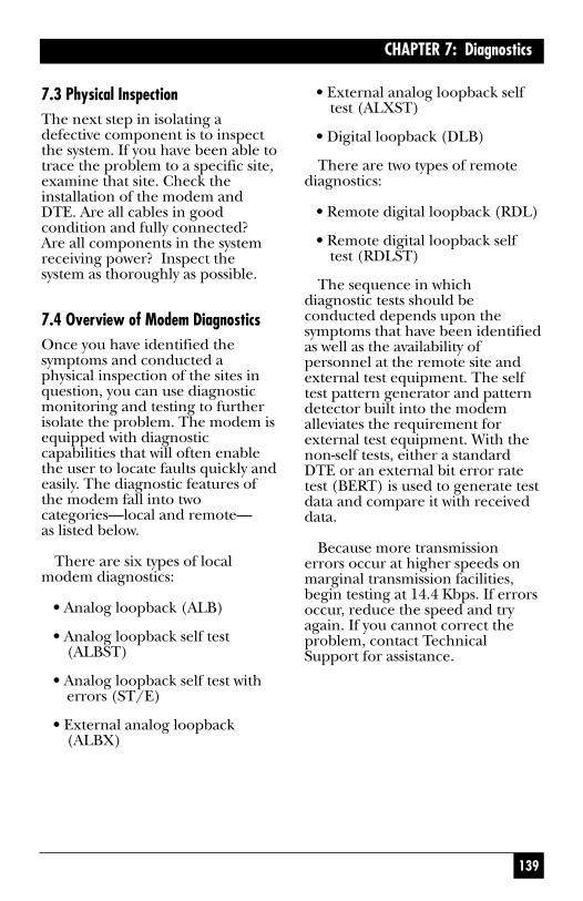
7.3 Physical InspectionThe next step in isolating adefective component is to inspectthe system. If you have been able totrace the problem to a specific site,examine that site. Check theinstallation of the modem andDTE. Are all cables in goodcondition and fully connected?Are all components in the systemreceiving power? Inspect thesystem as thoroughly as possible.
7.4 Overview of Modem DiagnosticsOnce you have identified thesymptoms and conducted aphysical inspection of the sites inquestion, you can use diagnosticmonitoring and testing to furtherisolate the problem. The modem isequipped with diagnosticcapabilities that will often enablethe user to locate faults quickly andeasily. The diagnostic features ofthe modem fall into twocategories—local and remote—as listed below.
There are six types of localmodem diagnostics:
• Analog loopback (ALB)
• Analog loopback self test(ALBST)
• Analog loopback self test witherrors (ST/E)
• External analog loopback(ALBX)
• External analog loopback selftest (ALXST)
• Digital loopback (DLB)
There are two types of remotediagnostics:
• Remote digital loopback (RDL)
• Remote digital loopback selftest (RDLST)
The sequence in whichdiagnostic tests should beconducted depends upon thesymptoms that have been identifiedas well as the availability ofpersonnel at the remote site andexternal test equipment. The selftest pattern generator and patterndetector built into the modemalleviates the requirement forexternal test equipment. With thenon-self tests, either a standardDTE or an external bit error ratetest (BERT) is used to generate testdata and compare it with receiveddata.
Because more transmissionerrors occur at higher speeds onmarginal transmission facilities,begin testing at 14.4 Kbps. If errorsoccur, reduce the speed and tryagain. If you cannot correct theproblem, contact TechnicalSupport for assistance.

140
MODEM 32144
7.5 How to Select and Activate Tests7.5.1 FRONT-PANEL CONTROL
Tests are accessed and activated inthe same way options are selected:by using the LCD and front-panelpushbuttons (as explained inChapter 3). To find the LCD screenfor a specific test, refer to the LCDflow chart (DIAGNOSTIC ANDCONTROL FUNCTIONS)included with this manual. Onceyou have accessed the screen for aspecific test, press pushbutton 1 tobegin the test (select ON). A teststatus screen will then beautomatically displayed. Todeactivate a test, press the ENTpushbutton and then pushbutton3. (The ENT button cannot beused to exit the text screen untilthe test has been deactivated.)
NOTEFor valid test results, errorcorrection must be disabledbefore diagnostic tests arerun. To disable errorcorrection, set the V.42Mode option to OFF.
7.5.2 RUNNING TESTS IN HAYES MODE
In Hayes emulation mode only,most of the diagnostic testsavailable on the modem can beactivated via the DTE keyboard byusing the &T commands listed inSection 5.4. The duration of a testcan be set by assigning a value toregister S18. For example, ATS18=30 sets the test time to 30seconds. The command &TOterminates a test. For furtherinformation, see Section 5.4.
7.5.3 REMOTE TEST CONTROL
You can configure the modem toignore or accept requests fromremote modems to initiate tests onyour modem. To access the remotetest control option, select TESTfrom SETUP screen 4. Then selectRMT from the TEST OPTIONSscreen. From the REMOTE TESTscreen, select ENABLE to allowremote test initiation or DISABLEto refuse remote test requests.
7.6 Diagnostic Monitoring: StatusScreens To obtain additional informationabout the status of thecommunications system, observethe status screen described in thefollowing sections. To view thesescreens, push the ENT button untilthe EIA status screen appears. Usethe right arrow pushbutton toadvance to other status screens.
7.6.1 EIA STATUS SCREEN
The EIA status screen indicates theoperational status of the modem aswell as the condition of certain EIARS-232 leads. The abbreviationsthat may appear are identifiedbelow; however, typically, only a fewof these abbreviations will bedisplayed during actual operation.

141
CHAPTER 7: Diagnostics
D TR MR RS CS TD9600 TM ER CD RD
Handshake Display
When two modems establish aconnection, they engage in anexchange known as a handshake.While a handshake is taking place,the modem displays several codesranging from H-01 to H-28 in thelower left corner of the EIA statusscreen. A handshake typically lastsfor up to 12 seconds and isaccompanied by various audibletones.
Checksum Screens
By pressing pushbutton 1 while theEIA status screen is displayed, youcan access two checksum screens,one for the main checksum andone for the data pump transmitterand receiver checksums. Thesechecksums provide data intendedfor use by servicing personnel. Thechecksum screens also show thesoftware revision levels (which arealso shown on the power-onscreen).
7.6.2 OTHER STATUS SCREENS
QUALITY SCREEN. The qualityscreen displays the quality of thereceived signal carrier as a numericvalue and as a horizontal bargraph. A low numeric valueindicates good signal quality. Thebest possible signal quality isindicated when the bar graphextends all the way to the rightedge of the LCD.
D=Dial line occupied
R=Ringing (R appears in sameposition as D.)
S=Connection secured by securityhandshake (S appears in sameposition as D. S and D may flashalternately.)
TR=Data Terminal Ready
MR=Data Set Ready
RS=Request to Send
CS=Clear to Send
TD=Transmit Data
9600, 4800, etc. = Data speed(“idle”—meaning the modem isoff-line—or H-01, H-14, etc., mayalso be displayed in the data speedposition; see following text.)
TM=Test mode
ER=Error (poor signal quality)
CD=Carrier Detect
RD=Receive Data

142
MODEM 32144
LINE LEVELS SCREEN. Thisscreen shows the preset level of thetransmit signal (TX) and themeasured level of the receivesignal (RX).
The RX value is the approximatelocal receive level of the incomingsignal. The range of measurementfor RX is from 0 to –43 dBm in 1.5-dBm increments. If the signal levelis less than the carrier detectthreshold, <CD will be displayed.
ECHO CHARACTERISTICSSCREEN. This screen displays thecharacteristics of the echo portionof the receive signal. Specifically, itshows milliseconds of delay and theoffset frequency in Hertz.
CHANNEL FREQUENCYOFFSET. This screen displays thefrequency offset of the receivesignal in Hertz.
THROUGHPUT SCREEN. Thisscreen functions only if errorcorrection has been enabled. Itshows the rate (in bits per second)at which characters are beingaccepted by the modem from theDTE.
PACKET SCREEN. The packetscreen functions only when errorcorrection is enabled. It has threecomponents, as explained next.
• SIZE. Shows size of data packets(MNP) or blocks (V.42/V.42bis) currently beingtransmitted. MNP uses“shorter” packets to transmitthrough noisy lines and“longer” packets (which allowgreater throughput) when lineconditions are good. Themaximum MNP packet size is256 characters (MNP classes 4and 5) or 64 (MNP classes 1-3).The block size for V.42/V.42 bisis fixed at 128 characters.
• TRANSMITTED (TX). Numberof packets or blocks transmittedsince the connection wasestablished (or since counterreset).
• ERRORS (ER). Number ofretransmissions (due to dataerrors) since the connectionwas established (or since thecounter was reset).
To reset the TX and ER counters,press pushbutton 2 while thepacket screen is displayed.
MODE AND RATE SCREEN.This screen shows the followingdata:
• MODE. Below MODE, thisscreen indicates the error-correction status:
- NORMAL, Error correction andbuffer mode are both inactive.

143
CHAPTER 7: Diagnostics
- V42, V.42 error correction(LAPM) is active.
- V42 bis, V.42 bis error correction(LAPM with data compression)is active.
- MNP 01 – MNP 05, MNP errorcorrection is active.
- BUFFER, Buffer mode is active.
- OFFLINE, Modem is off-line.
• RATE. This screen shows thedata rate of the DTE.
7.7 Rate Change ScreenIf V.32bis mode and the RateRenegotiation Procedure (RRP)option are both enabled, themodem will automatically adjustduring data transmission to ahigher or lower data rate,depending on the receive signalquality. For diagnostic purposes,the RATE screen (accessed fromscreen 3 of the MAIN MENU) maybe used to manually initiate speedrenegotiation from the front panel,as explained below.
The RATE screen is displayedonly if V.32 bis mode is enabled(via Summary Setup, V.32 Modeoption).
If you select DOWN from theRATE screen, the modem will fallback to the next lower speed. If youselect UP, the modem will fallforward to the next higher speed—if the signal quality is good enough.The range within which themodem can fall forward or fallback is limited by the minimumand maximum rates set via theSpeed Limit option. After youselect UP or DOWN, the LCD willautomatically switch to the EIAstatus screen so you can see theresult of the rate change request(i.e., the current data rate, which isdisplayed in the lower left corner ofthe EIA status screen). However, ifthe local modem has reached theminimum or maximum speed, itwill not switch to the EIA statusscreen.
NOTEA request to increase thedata rate may result in nochange in the data rate if thesignal quality is poor.
If you manually initiate speedrenegotiation with RRP enabled,the modem will automaticallyrenegotiate the speed (again) afterreceiving good signal quality for 4 seconds. If the originate modemattempts to negotiate a rate that is lower than the minimum ratesetting of the answer modem, theanswer modem will disconnect(GSTN cleardown).
144
MODEM 32144
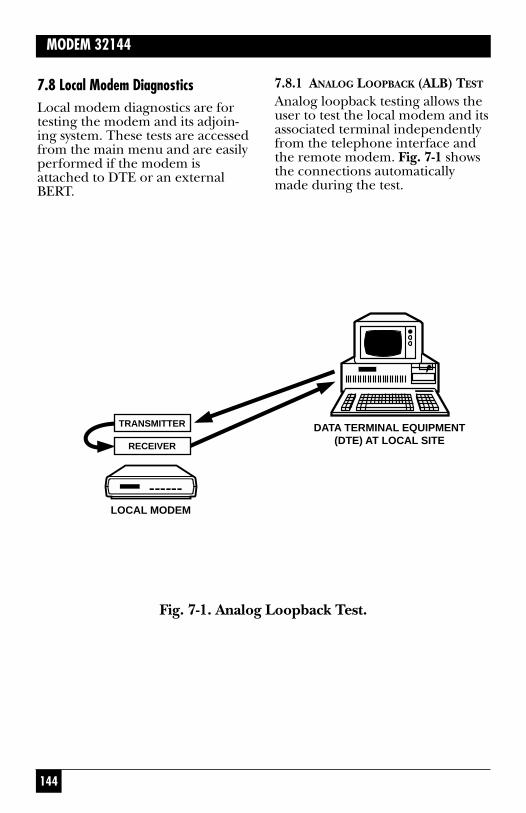
7.8 Local Modem Diagnostics Local modem diagnostics are fortesting the modem and its adjoin-ing system. These tests are accessedfrom the main menu and are easilyperformed if the modem isattached to DTE or an externalBERT.
7.8.1 ANALOG LOOPBACK (ALB) TEST
Analog loopback testing allows theuser to test the local modem and itsassociated terminal independentlyfrom the telephone interface andthe remote modem. Fig. 7-1 showsthe connections automaticallymade during the test.
LOCAL MODEM
DATA TERMINAL EQUIPMENT(DTE) AT LOCAL SITE
TRANSMITTER
RECEIVER
Fig. 7-1. Analog Loopback Test.

145
CHAPTER 7: Diagnostics
In Hayes emulation mode only,the ALB test can be initiated usingthe command &T1 (preceded byAT). In any mode, the ALB test canbe initiated by using the modem’sfront panel controls, as explainedin the following paragraphs.
Make sure the modem is idle,that the data rate is the same asthat of the DTE and that the DTRcircuit is on. (If TR is present onthe EIA status screen, the DTRcircuit is on.)
From screen 2 of the LCD MAINMENU, select TEST. This will takeyou to screen 1 of the LOCALTEST menu, where ALB will bedisplayed as one of the testselections. Select ALB.
The ANALOG LOOPBACKscreen will be displayed, with ONand OFF as the possible selections.
Select ON to activate the test. (Ingeneral, the DSR during ALB testoption discussed in chapter shouldbe left ON—the default selection—to avoid disrupting the DTE andDTE software operations.)
The EIA status screen will bedisplayed while the test is beingconducted. Ensure that test data is being generated. Watch for dataerrors. By transmitting test dataand comparing it with the receivedcopy, the DTE and modem arechecked for proper operation.
To end the test, press the ENTpushbutton to return to theANALOG LOOPBACK screen, and then select OFF.
7.8.2 ANALOG LOOPBACK SELF-TEST(ALBST)In the analog loopback self-test, the modem is placed in analogloopback and data is sent andreceived by an internal 511-bitpattern generator and receiver;therefore, no DTE or externalBERT is necessary. Fig. 7-2 showsthe data flow for this test.

146
MODEM 32144
Fig. 7-2. Analog Loopback Self Test (ALBST).
The SELFTEST screen will bedisplayed, with ON and OFF as thepossible selections. Select ON toactivate the test. The EIA statusscreen will be displayed while thetest is being conducted. If “ER” ispresent on the front panel, dataerrors have occurred. The ERindicator may flash on when thetest is first turned on, but it shouldquickly go out and remain off untilthe end of the test.
TRANSMITTER
PATTERNGENERATOR
RECEIVER
PATTERNDETECTOR
In Hayes mode only, the ALBST can be initiated using thecommand &T8 (preceded by AT).In any mode, the ALBST can beinitiated by using the modem’sfront-panel controls, as follows:
From screen 2 of the LCD MAINMENU, select TEST. This will takeyou to screen 1 of the LOCALTEST menu, where ALBST will be visible as one of the selections.Select ALBST.
147
CHAPTER 7: Diagnostics
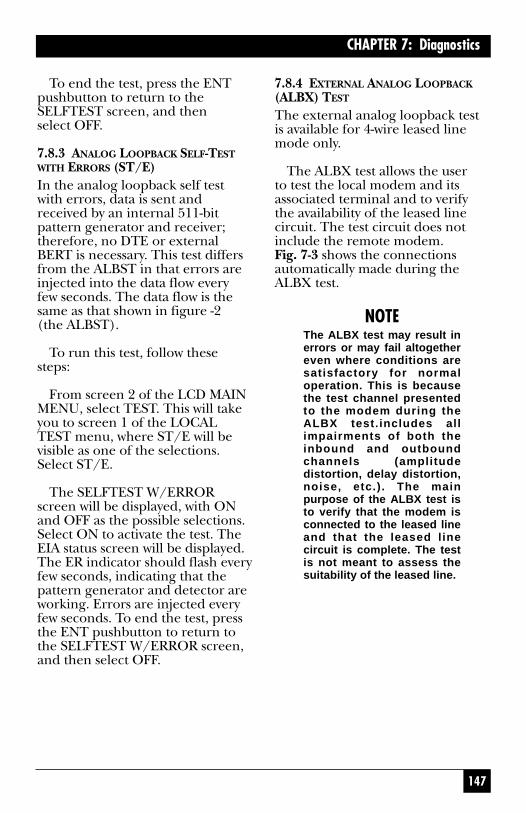
To end the test, press the ENTpushbutton to return to theSELFTEST screen, and then select OFF.
7.8.3 ANALOG LOOPBACK SELF-TESTWITH ERRORS (ST/E)In the analog loopback self testwith errors, data is sent andreceived by an internal 511-bitpattern generator and receiver;therefore, no DTE or externalBERT is necessary. This test differsfrom the ALBST in that errors areinjected into the data flow everyfew seconds. The data flow is thesame as that shown in figure -2 (the ALBST).
To run this test, follow thesesteps:
From screen 2 of the LCD MAINMENU, select TEST. This will takeyou to screen 1 of the LOCALTEST menu, where ST/E will bevisible as one of the selections.Select ST/E.
The SELFTEST W/ERRORscreen will be displayed, with ONand OFF as the possible selections.Select ON to activate the test. TheEIA status screen will be displayed.The ER indicator should flash everyfew seconds, indicating that thepattern generator and detector areworking. Errors are injected everyfew seconds. To end the test, pressthe ENT pushbutton to return tothe SELFTEST W/ERROR screen,and then select OFF.
7.8.4 EXTERNAL ANALOG LOOPBACK(ALBX) TEST
The external analog loopback testis available for 4-wire leased linemode only.
The ALBX test allows the user to test the local modem and itsassociated terminal and to verifythe availability of the leased linecircuit. The test circuit does notinclude the remote modem. Fig. 7-3 shows the connectionsautomatically made during theALBX test.
NOTEThe ALBX test may result inerrors or may fail altogethereven where conditions aresatisfactory for normaloperation. This is becausethe test channel presentedto the modem during theALBX test.includes allimpairments of both theinbound and outboundchannels (amplitudedistortion, delay distortion,noise, etc.). The mainpurpose of the ALBX test isto verify that the modem isconnected to the leased lineand that the leased linecircuit is complete. The testis not meant to assess thesuitability of the leased line.

148
MODEM 32144
The ALBX test can be initiatedby using the modem’s front panelcontrols, as explained in thefollowing paragraphs.
Make sure the local modem isnot in communication with theremote modem, that the data rateis the same as that of the DTE andthat the DTR circuit is on. (If TR ispresent on the EIA status screen,the DTR circuit is on.)
From screen 2 of the LCD MAINMENU, select TEST. Go to screen 2of the LOCAL TEST menu andselect ALBX.
LOCAL MODEM
DATA TERMINAL EQUIPMENT(DTE) AT LOCAL SITE
RECEIVER
EXTERNAL LOOPBACK(LEASED LINE)
TRANSMITTER
Fig. 7-3. External Analog Loopback (ALBX) Test.
149
CHAPTER 7: Diagnostics
The ANALOG LOOP(EXT)screen will be displayed, with ONand OFF as the possible selections.
Select ON to activate the test. (Ingeneral, the DSR during ALB testoption discussed in chapter shouldbe left ON—the default selection—to avoid disrupting the DTE andDTE software operations.)
The EIA status screen will bedisplayed while the test is beingconducted. If no external loopbackis present, the status screen willdisplay an “IDLE” message. If aloopback is present, handshake-sequence codes will appear (H-01,etc.), followed by the modemspeed. Make sure that test data isbeing generated. Watch for dataerrors. By transmitting test dataand comparing it with the receivedcopy, the DTE and modem arechecked for proper operation.During the ALBX test, RD (receivedata) may appear on the statusscreen even though no data isbeing received—this is normal.
On a flat line, the MODEMmodem in ALBX test mode willtrain and remain running acrossthe following range of signal loss:in V.32 mode, 0–51 dBm (0–52dBm at 12.0 Kbps); for V.33operation, 0-47 dBm; and for Bell208A/B operation, 0–37 dBm. Ifsignal loss exceeds these limits, thetest may not start or may be halted.
During the ALBX test, themodem will attempt to retrainupon loss of carrier. In switchedcarrier mode, the modem willattempt to retrain upon loss ofRTS.
To end the test, press the ENTpushbutton to return to theANALOG LOOP(EXT) screen, and then select OFF.
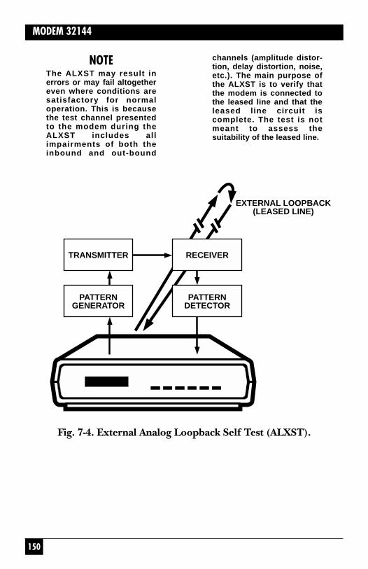
7.8.5 EXTERNAL ANALOG LOOPBACKSELF-TEST (ALXST)The external analog loopback selftest is available for 4-wire leasedline mode only.
The ALXST places the modem inanalog loopback and causes data tobe sent and received by an internal511-bit pattern generator andreceiver; therefore, no DTE orexternal BERT is necessary. Asshown in Fig. 7-4, the test circuitincludes the leased lines (theexternal loopback).
150
MODEM 32144
NOTEThe ALXST may result inerrors or may fail altogethereven where conditions aresatisfactory for normaloperation. This is becausethe test channel presentedto the modem during theALXST includes allimpairments of both theinbound and out-bound
channels (amplitude distor-tion, delay distortion, noise,etc.). The main purpose ofthe ALXST is to verify thatthe modem is connected tothe leased line and that theleased line circuit iscomplete. The test is notmeant to assess thesuitability of the leased line.
TRANSMITTER
PATTERNGENERATOR
RECEIVER
PATTERNDETECTOR
EXTERNAL LOOPBACK(LEASED LINE)
Fig. 7-4. External Analog Loopback Self Test (ALXST).
151
CHAPTER 7: Diagnostics
The ALXST can be initiated from the modem’s front panel, as follows:
From screen 2 of the LCD MAINMENU, select TEST. Go to screen 2of the LOCAL TEST menu andselect ALXST.
The ANALOG ST (EXT) screenwill be displayed, with ON and OFFas the possible selections. SelectON to activate the test.
The EIA status screen will bedisplayed while the test is beingconducted. If no external loopbackis present, the status screen willdisplay an “IDLE” message. If aloopback is present, handshakesequence codes will appear,followed by the modem speed. If“ER” is present on the front panel,data errors have occurred. The ERindicator may flash on when thetest is first turned on, but it shouldquickly go out and remain off untilthe end of the test.
The information at the end ofthe previous section (for the ALBXtest) concerning signal loss, loss ofcarrier and loss of RTS also apply tothe ALXST.
To end the test, press the ENTpushbutton to return to theANALOG ST (EXT) screen, and then select OFF.
7.8.6 DIGITAL LOOPBACK TEST (DLB)Digital loopback testing determinesthe operational performance of thelocal modem, the remote modem,and the telephone line as acomposite system. For this test, datamust be sent and received at theremote modem. This testregenerates the data and loops itback to the remote modem. As withthe ALB test, a comparison of theresults of the DLB test can indicatewhether or not the DTE isperforming satisfactorily. Acomparison of the results of theALB and DLB tests can helpdetermine whether the modem orthe telephone line is defective.
In the DLB test, the data to besent and received is originated andchecked by the DTE or externalBERT. Fig. 7-5 shows the data flowfor this test.

152
MODEM 32144
Fig. 7-5. Digital Loopback (DLB) Test.
DATA TERMINAL EQUIPMENT(DTE) AT LOCAL SITE
REMOTEMODEM
RECEIVER
LOCAL MODEM
TRANSMITTER
RECEIVER
TRANSMITTER
In Hayes mode only, the DLB testcan be initiated using thecommand &T3 (preceded by AT).In any mode, the DLB test can beinitiated using the modem’s front-panel controls, as follows:
From screen 2 of the LCD MAINMENU, select TEST. Go to screen 2of the LOCAL TEST menu andselect DLB.
The DIGITAL LOOPBACKscreen will be displayed, with ONand OFF as the possible selections.Select ON to activate the test. TheEIA status screen will be displayedwhile the test is being conducted.Make sure that test data is beinggenerated. Watch for data errors.By transmitting test data andcomparing it with the receivedcopy, the DTE is checked forproper operation. To end the test, press the ENT pushbutton to return to the DIGITALLOOPBACK screen, and thenselect OFF.

153
CHAPTER 7: Diagnostics
7.9 Remote Modem DiagnosticsThe modem is capable ofperforming two tests on compatibleremote modems: remote digitalloopback (RDL) and remote digitalloopback self-test (RDLST). If aproblem is encountered and thelocal modem passes all diagnostictests, the local modem can test theremote modem.
There are two (noncontiguous)REMOTE TEST screens on themodem LCD: (1) The remote testsare initiated from the REMOTETEST menu. (Select RMT fromMAIN MENU screen 2, and thenselect TEST. Then select the testtype.) (2) A remote test cannot be initiated unless the Remote Testoption is enabled on the remotemodem. This option (alsoREMOTE TEST on the LCD) isaccessed via SETUP screen 4.
7.9.1 REMOTE DIGITAL LOOPBACK(RDL) TEST
The RDL test (Fig. 7-6) allowstesting of the local modem, remotemodem and telephone line fromthe local site.
In Hayes mode only, the RDL test can be initiated using thecommand &T6 (preceded by AT).In any mode, the RDL test can beinitiated from the modem’s frontpanel, as follows:
Both modems should be on-lineand should be tested at the datarate used by the DTE. Ensure thatthe DTR circuit is on. (If TR ispresent on the EIA status screen,the DTR circuit is on.)
From screen 2 of the MAINMENU, select RMT, and then selectTEST. From the REMOTE TESTmenu, select RDL.

154
MODEM 32144
Fig. 7-6. Remote Digital Loopback (RDL) Test.
7.9.2 REMOTE DIGITAL LOOPBACKSELF-TEST (RDLST)The RDLST allows testing of thelocal modem, remote modem andtelephone line from the local siteas did the previous test, except that the test data is generated byinternal modem circuitry asopposed to a DTE or externalBERT. Fig. 7-7 shows theconnections automatically made during the test.
DATA TERMINAL EQUIPMENT(DTE) AT LOCAL SITE
LOCALMODEM
RECEIVER
REMOTE MODEM
TRANSMITTER
RECEIVER
TRANSMITTER
From the REMOTE DIGITLOOP screen, select ON to activatethe test. The status screen will bedisplayed as the test is beingconducted. Make sure that test datais being generated. Watch for dataerrors. By transmitting test dataand comparing it with the receivedcopy, the modems as well as thetelephone line can be checked forproper operation.
To end the test, press the ENTpushbutton to return to theREMOTE DIGIT LOOP screen,and then select OFF.

155
CHAPTER 7: Diagnostics
In Hayes mode only, the RDLST can be initiated using thecommand &T7 (AT &T7). In anymode, the RDLST test can beinitiated from the front panel asfollows:Both modems must be on-line.From screen 2 of the MAIN MENU,select RMT, and then select TEST.From the REMOTE TEST menu,select RDLST.
From the RDL SELFTESTscreen, select ON to activate thetest. The status screen will bedisplayed as the test is beingconducted. If “ER” is present onthe status screen, the modem isdetecting errors. If numerouserrors are detected, steps should betaken to try to identify their source.
PATTERNGENERATOR
PATTERNDETECTOR
TRANSMITTER
RECEIVER
TRANSMITTER
RECEIVER
LOCAL MODEM
REMOTE MODEM
Fig. 7-7. Remote Digital Loopback Self Test.
128
MODEM 32144
6.1.2 2 = DIALER MODE (DIAL V.25BIS SCREEN)If you enable the V.25 bisautodialer using the Dialer Modeoption, no other options will bechanged. To enable the autodialerthis way, select DIALER fromSETUP screen 2. Then press theright arrow pushbutton to go to theDIAL V25 bis screen (screen 2).Select the V.25 bis data protocolthat is appropriate for the DTE tobe used: asynchronous (Asyn);synchronous, character-oriented(Syn_c); or synchronous, bit-oriented (Syn_b).
6.1.3 DTR DIALING IN V.25 BIS MODE
An alternative to using the V.25bisCRS command to dial a storednumber is to use the DTR dialingoption. With DTR dialing enabled,the autodialer will dial the numberstored in phone cell 0 when DTRgoes high for at least 50 ms.
To enable V.25 bis DTR dialing,use the Summary Setup feature (asdescribed in appendix ) to changethe parameter for Penril/V25 bisDTR dialing to 0. Do not selectDTR dialing via the front-panelDIALER screen; this will not enableDTR dialing for V.25 bis mode. TheSummary Setup Penril/V25 bisDTR dialing option applies toeither V.25 bis mode or Penrilmode—whichever is enabled;therefore, for V.25 bis DTR dialing,the V.25 bis autodialer must beenabled.
6.2 V.25 bis Autodialer CommandsIn asynchronous applications, V.25bis commands are issued directlyfrom the DTE keyboard or throughcommunications software. Insynchronous applications, the V.25bis commands can be used tofacilitate computer-controlledcommunications.
Punctuation and spaces may beused with V.25 bis commands forclarity, but they are not required. If used, they will be ignored by the modem. One exception is the colon (:), which instructs theautodialer to wait for a dial tone.
The V.25 bis commands aredescribed below and aresummarized in Table 6-1. See Table6-3 for explanation of the codesthat may be displayed in responseto commands.
CIC - CONNECT NEXTINCOMING CALL. The CICcommand instructs the autodialerto answer the next incoming call.After the modem goes off hook,the modem will answer the nextcall only if auto-answer is enabledfrom the front panel.

129
CHAPTER 6: V.25 bis Autodialer
CRN - CALL REQUEST, NUMBERPROVIDED. (Syntax: CRN5557979) By using the CRNcommand, you can dial a numberdirectly from the DTE keyboard.Numbers from 0 through 9 can be dialed, and if tone dialing isenabled, the characters A, B, C, D,# and * can also be dialed.
The dialing parameters listed intable -2 can be used with the CRNcommand to specify how or when a number should be dialed. Forexample, the command line CRN:T3331234 instructs the autodialerto wait for a dial tone (:) and thentone dial (T) the number 333-1234.
CRS - CALL REQUEST, ADDRESSPROVIDED. (Syntax: CRS 2) TheCRS command allows you to dial astored number simply by specifyingits memory address (phone cell).In the example given above, theautodialer will dial the numberstored in phone cell 2. Thenumber must first be stored in the specified phone cell using the PRN command (Table 6-1).
DIC - DISREGARD INCOMINGCALLS. The DIC commandinstructs the autodialer not toanswer incoming calls. The DICcommand is canceled when theCIC command is issued or themodem is reset. In the event of a reset, the modem will answer ifauto-answer is enabled from thefront panel.
PRN - PROGRAM NORMAL(STORE NUMBER). (Syntax: PRN1;5551212) The PRN command isused to store a number or dialstring in a phone cell so it can bedialed later by specifying only thephone cell number. As shownabove, PRN is followed by thephone cell number, a semicolonand the phone number to bestored. After a number is stored, it can be dialed using the CRScommand. Any of the characterslisted in Table 6-2 may be stored.
Ten phone cells (0-9) areavailable for phone numberstorage. Each cell can hold amaximum of 25 characters,although cells 1 through 9 willautomatically expand to the nextempty phone cell if loaded withmore than 25 digits. Even if astored number is continued toanother cell, the maximumnumber of characters that can bestored is 36. You cannot store anumber in a phone cell unless it is empty. To clear a cell, enter PRNand the phone cell number,without a phone number. Only cell 0 can be accessed from themodem’s front panel (via thePHONE LCD screen).

130
MODEM 32144
RLN - REQUEST STOREDNUMBER(S). RLN can be used torequest a list of all stored numbersor to show the number stored in aspecific phone cell. RLN, usedalone, requests a list of all storednumbers. The DTE display willshow the stored numbers as follows:LSN 0; 301 555 1234LSN 1; 301 123 4567LSN 2; 301 555 5555
(and so on through phone cell 9)
If a phone cell number isspecified after RLN, e.g., RLN 5,the DTE display will show only thenumber stored in the specifiedphone cell.
How to Disconnect a Call
To disconnect a call locally, useyour communication software toforce DTR to go low, or selectHANGUP from the front-panelAUTO-DIAL screen.
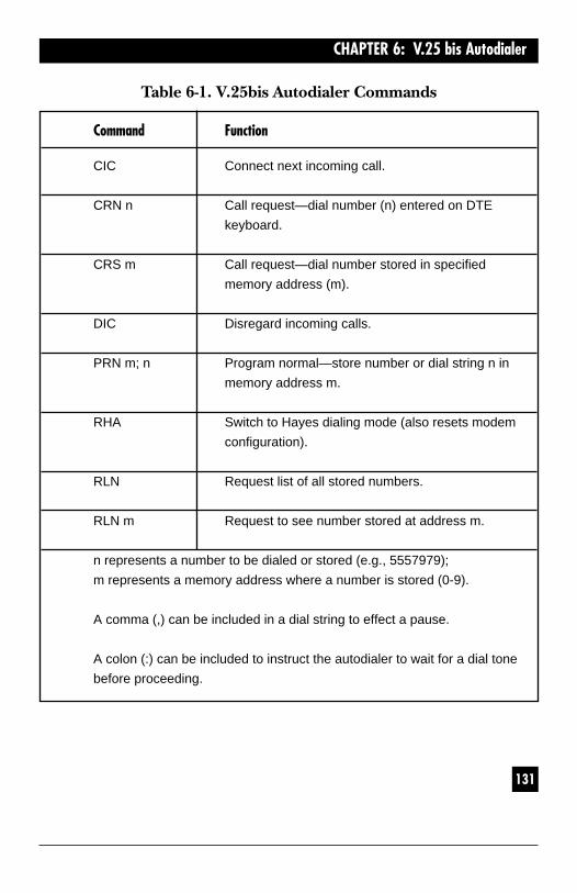
131
CHAPTER 6: V.25 bis Autodialer
Table 6-1. V.25bis Autodialer Commands
Command Function
CIC Connect next incoming call.
CRN n Call request—dial number (n) entered on DTE
keyboard.
CRS m Call request—dial number stored in specified
memory address (m).
DIC Disregard incoming calls.
PRN m; n Program normal—store number or dial string n in
memory address m.
RHA Switch to Hayes dialing mode (also resets modem
configuration).
RLN Request list of all stored numbers.
RLN m Request to see number stored at address m.
n represents a number to be dialed or stored (e.g., 5557979);
m represents a memory address where a number is stored (0-9).
A comma (,) can be included in a dial string to effect a pause.
A colon (:) can be included to instruct the autodialer to wait for a dial tone
before proceeding.

132
MODEM 32144
6.3 Dialing ParametersTable 6-2 lists dialing parametersthat may be used with the CRNcommand to modify dialingoperations.
Table 6-2. V.25 bis Dialing Parameters(Table also applies to Dumb mode and Bell 208 operation)
Characters that can be pulse or tone dialed: 0-9Can only be tone dialed: A, B, C, D, #, and *
L Links a phone number to
another number to be dialed
as an alternate when the primary
number is busy or does not
answer. See L—Link in Section 5.4.
P Sets pulse dialing mode.
T Sets tone dialing mode.
W or : (colon) Wait 30 seconds for dial tone before
proceeding.
[CR] or . Required at end of dial command line.
(carriage return [CR] is sent from DTE keyboard.
or period) Dumb/208 mode only: period has same
function, but may be entered via the
front panel (PHONE LCD screen).
, (comma) or < Pause before processing next character
in dial string.

133
CHAPTER 6: V.25 bis Autodialer
Table 6-2. V.25 bis Dialing Parameters(Table also applies to Dumb mode and Bell 208 operation)
Characters that can be pulse or tone dialed: 0-9Can only be tone dialed: A,B, C, D, # and *
@ Wait for silence.
! (exclamation) Flash hook
L, P, T, and W may be entered as upper or lowercase letters. Spaces or
hyphens (-) may be used as separators for clarity; they will have no effect.
6.4 V.25 bis Result CodesTable 6-3 explains the result codes,or responses that may be displayedon the DTE monitor in response toV.25 bis commands.

134
MODEM 32144
Table 6-3. V.25 bis Result Codes
Code Meaning Sent by—1
CFI AB Call failure—call aborted because of ORG
loss of DTR or because HANGUP was
selected from front-panel AUTO-DIAL
screen.
CFI CB Call failure because DCE is busy. ORG
(Modem dialing or handshaking as
a result of a front-panel dial
request.)
CFI ET Call failure because of busy signal. ORG
(Engaged tone.)
CFI ND Call failure—no dial tone. Modem did ORG
not detect dial tone or line current
during dialing or handshaking.
CFI NS Call failure—call request specified ORG
an address that does not contain
a stored number. (No stored
number.)
CFI NT Call failure—no answer tone. Remote ORG
unit answered but did not issue
answer tone.
1Column 3 indicates which modem sends the result code. (ANS/ORG indicates
answer and/or originate modem.)
A semicolon is used to separate parameters,. e.g., LSN 4;5559797.

135
CHAPTER 6: V.25 bis Autodialer
Table 6-3. V.25bis Result Codes (continued)
Code Meaning Sent by—1
CFI RT Call failure—ring tone. Ringback ORG
detected, but no answer.
CNX Call connecting. ANS/ORG
INC Incoming call. ANS
INV CU Invalid—command unknown. ANS/ORG
INV MS Invalid message (command) syntax. ANS/ORG
INV PS Invalid parameter value. Specified ANS/ORG
parameters are out of range for
command used.
LSN List of stored numbers. LSN is ANS/ORG
followed by memory address,
stored number, next memory
address and stored number, etc.
VAL Valid—command accepted; waiting ANS/ORG
for next command.

136
MODEM 32144
6.5 Message FormatThe message format for V.25 bisDTE-to-DCE communications issummarized below:
6.5.1 ASYNCHRONOUS
MARK|MESSAGE|CR|LF|MARK
This format uses one start bit, 8-bit data units, and a 1-unit stopbit. The 8-bit data units are formedby a 7-bit IA5 character and aneven parity bit.
6.5.2 SYNCHRONOUS, CHARACTER-ORIENTED
|SYN\SYN\STX|MESSAGE|ETX|
This format uses consecutive 8-bitdata units formed by a 7-bit IA5character and an odd parity bit.

137
CHAPTER 6: V.25 bis Autodialer
||FLAG|ADDR|CTRL|MESSAGE|FCS|FLAG|
Consecutive 8-bit data units areused within the message andsubmitted to the HDLC framing(zero insertion). The 8-bit dataunits are formed by a 7-bit IA5character and an off parity bit.
6.5.3 SYNCHRONOUS, BIT-ORIENTED
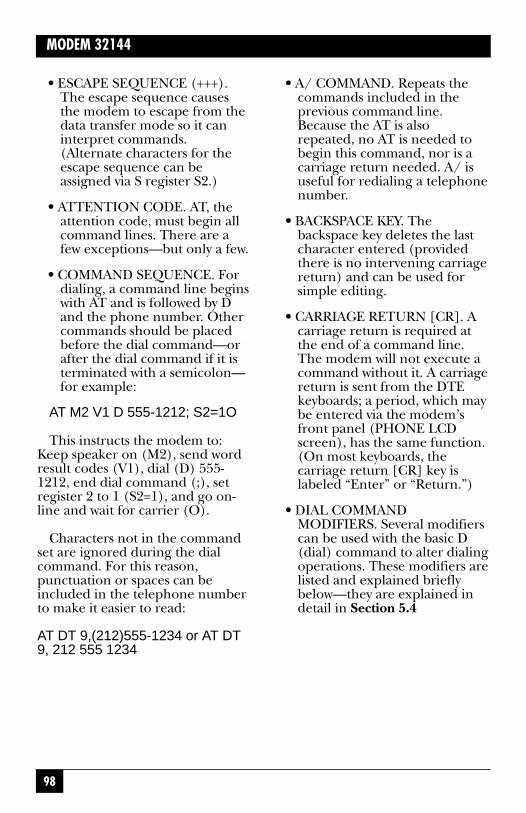
98
MODEM 32144
• ESCAPE SEQUENCE (+++).The escape sequence causesthe modem to escape from thedata transfer mode so it caninterpret commands.(Alternate characters for theescape sequence can beassigned via S register S2.)
• ATTENTION CODE. AT, theattention code, must begin allcommand lines. There are afew exceptions—but only a few.
• COMMAND SEQUENCE. Fordialing, a command line beginswith AT and is followed by Dand the phone number. Othercommands should be placedbefore the dial command—orafter the dial command if it isterminated with a semicolon—for example:
AT M2 V1 D 555-1212; S2=1O
This instructs the modem to:Keep speaker on (M2), send wordresult codes (V1), dial (D) 555-1212, end dial command (;), setregister 2 to 1 (S2=1), and go on-line and wait for carrier (O).
Characters not in the commandset are ignored during the dialcommand. For this reason,punctuation or spaces can beincluded in the telephone numberto make it easier to read:
AT DT 9,(212)555-1234 or AT DT9, 212 555 1234
• A/ COMMAND. Repeats thecommands included in theprevious command line.Because the AT is alsorepeated, no AT is needed tobegin this command, nor is acarriage return needed. A/ isuseful for redialing a telephonenumber.
• BACKSPACE KEY. Thebackspace key deletes the lastcharacter entered (providedthere is no intervening carriagereturn) and can be used forsimple editing.
• CARRIAGE RETURN [CR]. Acarriage return is required atthe end of a command line.The modem will not execute acommand without it. A carriagereturn is sent from the DTEkeyboards; a period, which maybe entered via the modem’sfront panel (PHONE LCDscreen), has the same function.(On most keyboards, thecarriage return [CR] key islabeled “Enter” or “Return.”)
• DIAL COMMANDMODIFIERS. Several modifierscan be used with the basic D(dial) command to alter dialingoperations. These modifiers arelisted and explained brieflybelow—they are explained indetail in Section 5.4

99
CHAPTER 5: Hayes Emulation Mode
Dial command modifiers:
L—Links a phone number toanother number to be dialed as analternate.
P—Sets pulse-dialing mode.
S=m—Dial number stored atmemory location m.
T—Sets tone-dialing mode.
W or : (colon)—Pause for 2seconds.
, (comma)—Pause for 2 seconds.
; (semicolon)—Return tocommand state after dialing.
@—Wait for silence.
! (exclamation)—Flash hook
With few exceptions, dialcommand modifiers will functiononly if they are used in a commandline with the D command orincluded in a stored number. Acarriage return of period must beused at the end of a dial string. Anexample of a command line withtwo dial modifiers is:
AT DT 9,555-1212
The modifier T instructs themodem to tone dial, and thecomma instructs it to pause afterdialing 9 before dialing theremaining digits.
MISSING PARAMETER. Amissing parameter is interpreted as a zero. For example, the Ecommand (echo) can be sent aseither E0 or E1, but if an E aloneis sent, the modem will interpret itas if an E0 was sent.
COMMAND BUFFER. Thecommand buffer can hold amaximum of 40 characters. If the command line exceeds 40characters, the modem refuses to execute any portion of thecommand line and sends an errormessage. The AT at the beginningof the command line, controlcharacters, and spaces do not takeup space in the command buffer.Punctuation (except for spaces)does take up space in thecommand buffer.
5.2 Result CodesResult codes (Table 5-2) aremessages sent by the modem to theDTE monitor in response to yourcommands. Result code options are selected using the V and Xcommands, as explained below.
Result codes may be words (V1command) or digits (V0). Wordcodes are preceded and followedby a carriage return, line feedsequence. Digit codes are onlyfollowed by a carriage return.
100
MODEM 32144
Result codes 0-4 comprise thebasic result code set: OK,CONNECT, RING, NO CARRIER,and ERROR. Codes 5-43 provideadditional response information, asexplained in Table 5-2. Variouscombinations of these codes can beenabled or disabled by using the Xcommand and its four parameters,as explained later under X—SELECT RESULT CODE.
NOTEWith the default Hayes modesettings in effect, themodem transmits resultcodes to the DTE. In someinstallations, this may causeundesirable interaction withthe attached DTE. If suchinteraction occurs, resultcodes for incoming callsshould be suppressed(using the command AT Q2).
5.3 Transmission SpeedThis section applies only toconnections made without errorcorrection or buffering (V.42/V.42bis, MNP and Buffer Modeoptions).
Transmission speed is governedby the speed of the system withwhich you wish to communicate.You must set the transmissionspeed of your computer by setting aswitch in the hardware or by issuinga software command. (Refer toyour computer documentation.)When the modem originates a call,it automatically detects and adjusts
to the transmission speed set whenthe communication port wasinitialized.
When answering a call, themodem determines thetransmission speed from the carriersignal of the originating modem.Change the speed (baud) setting of your equipment to match that ofthe remote system. Otherwise,unintelligible data will appear onyour screen. (Depending on theparameter used with the Xcommand, the speed will beindicated by the CONNECTresponse code.)
Autobaud
When a call is originated in Hayesmode, the AT attention codecauses the modem to autobaud.The speed at which the modemautobauds defines the speed limitfor subsequent connections andoverrides any front panel SpeedLimit or DTE Speed settings. If theunit is not autobauded, the defaultinterface rate is 38,400 bps.
NOTEIf AT is entered at one speedand followed by a carriagereturn [CR] at anotherspeed, the modem will notrecognize any furthercommands until a [CR] isentered at the same speedof the AT.
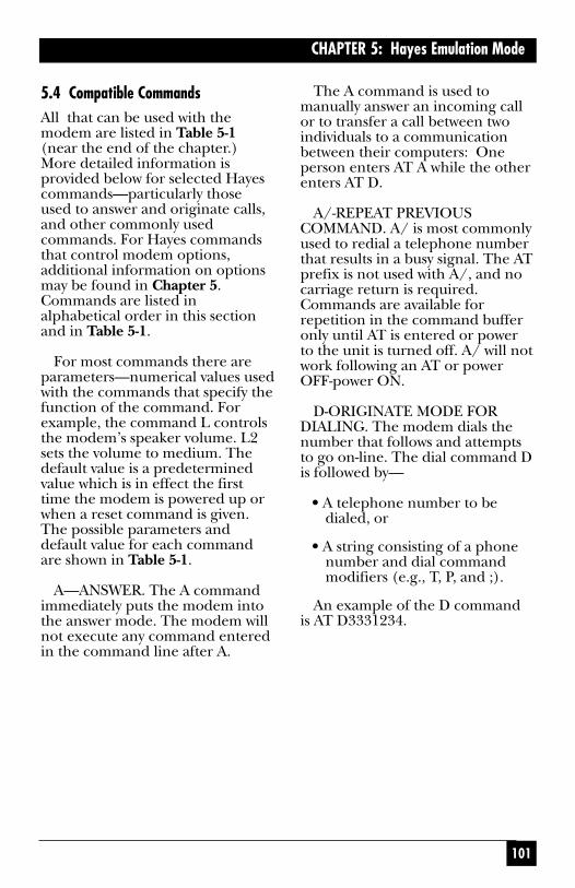
101
CHAPTER 5: Hayes Emulation Mode
5.4 Compatible CommandsAll that can be used with themodem are listed in Table 5-1(near the end of the chapter.)More detailed information isprovided below for selected Hayescommands—particularly thoseused to answer and originate calls,and other commonly usedcommands. For Hayes commandsthat control modem options,additional information on optionsmay be found in Chapter 5.Commands are listed inalphabetical order in this sectionand in Table 5-1.
For most commands there areparameters—numerical values usedwith the commands that specify thefunction of the command. Forexample, the command L controlsthe modem’s speaker volume. L2sets the volume to medium. Thedefault value is a predeterminedvalue which is in effect the firsttime the modem is powered up orwhen a reset command is given.The possible parameters anddefault value for each commandare shown in Table 5-1.
A—ANSWER. The A commandimmediately puts the modem intothe answer mode. The modem willnot execute any command enteredin the command line after A.
The A command is used tomanually answer an incoming callor to transfer a call between twoindividuals to a communicationbetween their computers: Oneperson enters AT A while the otherenters AT D.
A/-REPEAT PREVIOUSCOMMAND. A/ is most commonlyused to redial a telephone numberthat results in a busy signal. The ATprefix is not used with A/, and nocarriage return is required.Commands are available forrepetition in the command bufferonly until AT is entered or power to the unit is turned off. A/ will notwork following an AT or powerOFF-power ON.
D-ORIGINATE MODE FORDIALING. The modem dials thenumber that follows and attemptsto go on-line. The dial command Dis followed by—
• A telephone number to bedialed, or
• A string consisting of a phonenumber and dial commandmodifiers (e.g., T, P, and ;).
An example of the D commandis AT D3331234.

102
MODEM 32144
In response to this command, themodem dials the telephonenumber 333-1234, and then waitsfor a carrier tone from the distantmodem (default wait time, 30seconds). If the modem is able to establish a call, it gives aCONNECT result code, indicatingthat it is on-line. If it cannotconnect, it will use a different resultcode , such as NO CARRIER, BUSY,or NO DIALTONE.
The characters that can be dialedare 0 through 9, A, B, C, D, #, and*.
The dial command modifiers arelisted in the preceding CommandGuidelines section.
AT D—the dial commandwithout a telephone numbercauses the modem to pick upthe telephone line without dialinga number.
DS—DIAL STORED NUMBER.The DS command instructs themodem to dial a phone number ordial string previously stored usingthe &Z command. The syntax isDS=m, where m specifies thememory location where thenumber to be dialed will be stored.Up to ten numbers may be storedin memory locations 0-9. S=m maybe placed anywhere in the dialstring for example, AT D2345S=2will dial 2345 and the number
stored in memory location 2.H—TELEPHONE SWITCH
HOOK. The H command on-hook)is used to terminate a call. (On-hook corresponds to off-line.)H may also be used to alternatebetween voice and datatransmission during the same call(if your communication softwaresupports this capability).
The H1 command (off-hook)activates the telephone line relay,causing a dial tone to be sent (after a 2-second delay). For mostpurposes, this command is notnecessary, since the switch hook isautomatically activated when themodem originates or answers a call.
L—LINK. The L dial modifier isused to link one phone number toanother so that one may bedesignated as an alternate numberto be dialed if a connection cannotbe made to a primary number. TheL parameter must be used after aphone number, and prior to acarriage return or period. Anumber is used after L to specify;the memory address (0-9) thatcontains the number to be linkedto the first number:
AT D 555-1212 L5
103
CHAPTER 5: Hayes Emulation Mode
NOTEL may also be used in V.25bis mode with the CRNcommand (instead of AT D),in Dumb mode and in 208operation. In Dumb mode or208 operation, L is storedvia the PHONE screen. In allcases, L is used the sameway and has the samefunction as described here(except that AT D is notused.)
Two or more addresses may be linked in a cyclic fashion toalternate dialing until a connectionis established.
Contents of memory location 0:555-1212 L1
Contents of memory location 1:444-1234 L2
Contents of memory location 2:888-5555 L0
With the memory locationsloaded as shown above, if thecommand AT DS=0 is issued, theautodialer will go to location 0 anddial the number stored there. Ifunable to connect, the L1command stored in location 0 willdirect the autodialer to dial thenumber in location 1. In similarfashion, the L2 stored in memorylocation 1 directs the autodialer tolocation 2 (assuming a connectioncannot be made); and the L0command stored in location 2directs the autodialer back tolocation 0. The numbers will be
dialed in a loop until a connectioncan be established or until 10 callshave been attempted.
O—FORCED ON-LINE. Thiscommand applies to asynchronousoperation only. When the modemis on-line, you can return to thecommand state by entering theescape code (+++). After thedesired command has beenexecuted, use the O command to force the modem from thecommand state to the on-line state.
P—PULSE DIAL. The Pcommand instructs the modem topulse dial. It can be enteredanywhere in the dialing string:AT P5551212; or it can be enteredalone, followed by a carriagereturn, AT P, in which case allsubsequent telephone numbers will be pulse dialed. If the dialcommand does not specify whichdialing mode to use, the modemdefaults to the last mode specified.
S—MODIFY S REGISTER. This command is used to writeinformation to a specified Sregister. The syntax is Sr=n, where ris the number of the register to bemodified and n is the value to bewritten to it; for example:
AT S7=30
104
MODEM 32144
This command would change thevalue of register S7 to 30. If youenter just =5, the autodialer willchange the value of the last registerused to 5. More information on Sregisters is included later in thischapter.
S?—READ S REGISTER. Thiscommand instructs the autodialerto read the contents of thespecified S register. The syntax isSr?, where r specifies the register tobe read. For example, S7? reads thevalue of register S7. The value isdisplayed on the computer orterminal monitor. If you enter ? byitself, the autodialer will display thevalue of the last register used; if = isentered by itself, the autodialer willdisplay the number of the lastregister used (e.g., S2). Forinformation on how to interpret Sregister values, see Table 5-3.
T—TONE DIALING. Thiscommand causes a telephonenumber in the dial commandstring to be dialed using tonesignals. (See the P command above for additional information.)
W—WAIT FOR DIAL TONE.The W command (or colon) isused in a dial string to instruct themodem to wait for a dial tonebefore proceeding. The wait time(30 seconds by default) can beadjusted by changing the value inregister S7. If no dial tone isdetected within the specified time,the modem will hang up and give aNO DIALTONE result code (if this
result code is enabled by the Xcommand).
Z—RECALL STORED USERPROFILE. The Z command resetsthe modem and recalls a profile ofthe modem configuration settingspreviously saved using the &Wcommand. The profile isdesignated as profile 0 or profile 1when it is saved using the &Wcommand.
,—PAUSE. A comma causes themodem to pause for 2 seconds (ortime specified in register S8)before processing the nextcharacter in a dial string orcommand. This command is usedto place an outside call through aPBX switchboard, where 9 has tobe dialed to gain outside access—the pause allows time for the dialtone to occur before the modemdials the number.
AT D9,3331234
Similarly, a comma may be usedto cause the modem to wait for asecond dial tone before beginningto dial a telephone number.Multiple commas may be used toincrease the pause time.
;—FORCED COMMAND STATE.A semicolon placed at the end of adial command causes the modemto return to the command stateafter dialing without disconnecting.
The following examples illustratehow the ; command is used:
105
CHAPTER 5: Hayes Emulation Mode
The first example is a bankingtransaction: The command ATD333-1234; dials the bank’s phonenumber and returns the modem tothe command state. After the OKprompt is displayed on the DTE,the command AT D T 0901# isentered. This transmits theidentification number 0901 to the bank, and again returns themodem to the command state. Anaccount number and other datamay be transmitted in the sameway.
The second example illustratesone method of autodialing: Entera dial string that ends with asemicolon, for example, AT DT9,3331234. During the ring signal orwhen the call is answered, pick upthe phone and enter AT H. Youmay then use a telephoneconnected to the modem for voicecommunication.
@—WSAIT FOR SILENCEBEFORE DIALING. The @command is used to gain access toa system that does not provide adial tone. It tells the modem to waitfor 30 seconds or the time specifiedby a register S7 for one or morerings followed by 5 seconds ofsilence before processing the nextsymbol in the dial string.
!—INITIATE FLASH HOOK.The ! command causes the modemto go on-hook for 1/2 second. Thishas the same effect as holding theswitch-hook button on yourtelephone down for 1/2 second.
You may be able to use thiscommand for transferring calls.
&F—RECALL FACTORYCONFIGURATION. The &Fcommand restores the modem toits original factory configuration,using data stored in ROM.However, this change is notpermanent. If the modem is turnedoff or reset, the recalledconfiguration will be replaced withthe default stored profile. (See the&Y command.)
&V—VIEW ACTIVECONFIGURATION, ETC. Thiscommand displays the activemodem configuration, user profilesstored using the &W command,and phone numbers stored usingthe &Z command. When &V isinvoked, the DTE displays theconfiguration commands lastissued, including parameters used,and the values currently stored inthe S registers. The &V commandshould be issued as the lastcommand on a line.
&W—WRITE PROFILE TOMEMORY. The &W commandsaves the storable parameters of themodem’s active configuration bywriting the configuration profile tonon-volatile memory. By selectingeither &W0 or &W1, two differentuser profiles can be saved (profile 0or 1). One of these profiles will beautomatically restored wheneverthe modem is powered on or whenthe Z command is issued. (See the&Y and Z commands.)

106
MODEM 32144
The &W command cannot beused to write changes to the userprofiles if the modem front panelhas been disabled by the FrontPanel Control option.
The parameters listed belowcannot be stored—they are all setby changing S register values (asindicated in Table 5-3):
S1—Ring countS2—Escape-sequence character (ASCII 43)S3—Carriage-return character (ASCII 13)S4—Line-feed character (ASCII10)S5—Backspace character (ASCII08)S6—Wait time before blind dialingS7—Wait time for carrier/dial toneS8—Pause duration (effected by comma)S9—Carrier detect response timeS10—Delay: Lost carrier until hangup timeS11—DTMF tone durationS12—Escape-sequence guard timeS25—DTR detection
When the &W command is usedto save a configuration profile,stored phone numbers are notsaved as part of the profile.
&Z—STORE TELEPHONENUMBER. The &Z command isused to store a telephone numberthat can be subsequently dialed
using the DS (dial stored number)command. The syntax is &Zm=n,where m specifies the memorylocation where the phone numberor dial string will be stored and n isthe number or dial string to bestored. For example, AT &Z5=T1(301) 555-1212 will store thespecified number at memorylocation 5. Ten memory locationsare available: 0-9.
(The &Z command is also usedto store passwords, as explained inSection 4, Security Operation.)
For pulse dialing, digits 0through 9 can be stored; for tonedialing, 0 through 9, A through D,# and * can be stored. The dialcommand modifiers listed in theCommand Guidelines section canalso be stored.
Each memory location can hold amaximum of 24 digits, althoughlocations 1 through 9 willautomatically expand to the nextempty location if loaded with morethan 24 digits. Even if a storednumber is continued to anotherlocation, the maximum length is 36characters. (Attempting to dial adial string of more than 36characters will result in an ERRORmessage.) A memory locationcannot be used for storage unless itis empty. To delete an entry, enterAT&Zm=, where m is the memorylocation number. Only location 0can be accessed from the modem’sfront panel (via the PHONE LCDscreen).

107
CHAPTER 5: Hayes Emulation Mode
\S—VIEW STATUS OF V.42-RELATED CONFIGURATION.The \S command displays the activeV.42 error correctionconfiguration, stored V.42 profiles,and certain other data notdisplayed by the &V command.
5.5 RegistersThe modem includes 28 registers(S0-S27) that can be used tocontrol specific modem operationsin Hayes mode only. Each registerholds a value that serves as aspecific operating instruction forthe modem. Several of the Sregisters affect how the previouslydescribed commands will beexecuted.
The functions of the registersintended for user access areexplained below and summarizedin Table 5-3.
5.5.1 READING AND SETTING REGISTERS
Use the S command to read thevalue of a register or to change itsvalue.
To read the current value of aregister, use the command S?,where the number of the register isspecified between the S and the ?,as follows: S9?. The decimal valueof the register contents will then bedisplayed. Multiple registers may beread. For example, if you wish toread the current value in registersS0 and S7, enter
AT S0? S7?
A typical response might be001,030, OK, meaning that thevalues stored in registers S0 and S7are 1 and 30, respectively.
To set or change a parameter, usethe command S=, where thenumber of the register follows Sand a value between 0 and 255 (therange of values that can be assignedto the registers) follows the equalsign:
AT S0=5
This command will change thevalue stored in S0 to 5.
The S command can also be usedwithout ? or = to point to a registerthat will be subsequently read fromor written to without beingspecified. To illustrate this, if youenter
AT S7
a pointer is set to the address ofregister S7. As long as no other Scommand is entered, the registervalue can be requested at any timewithout specifying the number. Ifyou enter AT? the modem displaysthe current value in the S7 register.Similarly, if you enter AT=8 themodem will change the value in the S7 register to 8.
108
MODEM 32144
5.5.2 S REGISTER FUNCTIONS
This section describes the functionof individual S registers. Table 5-3 lists the range of possibleparameters and the default valuefor each S register. Only S registersthat are intended for user accessare listed.
S0—RING TO ANSWER ON.The value in this registerdetermines on what ring (first,second, third, etc.) the modem willanswer on. Setting S0 to 0 disablesauto-answer.
S1—RING COUNT. Register S1counts the number of ring signalsfor each incoming call. If morethan 8 seconds have passed sincethe last ring, S1 is cleared to zero.
S2—ESCAPE CODECHARACTER. The escape code iseffective for asynchronousoperation only. Values greater than127 will completely disable escapecode detection and prevent youfrom issuing a hangup command.
S3—CARRIAGE RETURN.Register S3 is effective forasynchronous operation only.Normally, the ASCII carriagereturn value, 13, is used.
S4—LINE FEED. This register is effective for asynchronousoperation only. The line-feedcharacter follows the carriage
return only when word result codeshave been selected (command V1).Line feed can be changed to a nullbut cannot be totally disabled.
S5—BACKSPACE. This register is effective for asynchronousoperation only. The value in S5defines the backspace character.Do not use values between 33 and126.
S6—BLIND DIALING WAITTIME. The value in S6 determineshow long the modem will wait afterpicking up the telephone line(going off-hook) before it begins todial. If S6 is set for less than 2seconds, the modem still waits 2seconds before dialing. If the X2 toX4 command is in effect, dial tonedetection will be enabled and blinddialing will be disabled, meaningthat the value in S6 will have noeffect.
S7—CARRIER/DIAL TONEWAIT TIME. This register controlstwo wait times—wait time forcarrier and, if W is included in thedial string, wait time for dial tone(or wait time for silence if @ isused).
S8—PAUSE TIME. The pausetime effected by a comma in a dialstring or other command line iscontrolled by register S8.
S9—CARRIER DETECTRESPONSE TIME. Register S9determines how long a carrier tonemust be present for the modem to
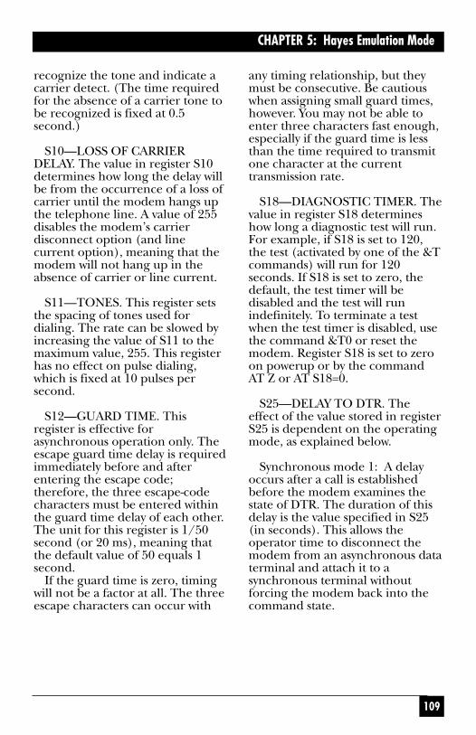
109
CHAPTER 5: Hayes Emulation Mode
recognize the tone and indicate acarrier detect. (The time requiredfor the absence of a carrier tone tobe recognized is fixed at 0.5second.)
S10—LOSS OF CARRIERDELAY. The value in register S10determines how long the delay willbe from the occurrence of a loss ofcarrier until the modem hangs upthe telephone line. A value of 255disables the modem’s carrierdisconnect option (and linecurrent option), meaning that themodem will not hang up in theabsence of carrier or line current.
S11—TONES. This register setsthe spacing of tones used fordialing. The rate can be slowed byincreasing the value of S11 to themaximum value, 255. This registerhas no effect on pulse dialing,which is fixed at 10 pulses persecond.
S12—GUARD TIME. Thisregister is effective forasynchronous operation only. Theescape guard time delay is requiredimmediately before and afterentering the escape code;therefore, the three escape-codecharacters must be entered withinthe guard time delay of each other.The unit for this register is 1/50second (or 20 ms), meaning thatthe default value of 50 equals 1second.
If the guard time is zero, timingwill not be a factor at all. The threeescape characters can occur with
any timing relationship, but theymust be consecutive. Be cautiouswhen assigning small guard times,however. You may not be able toenter three characters fast enough,especially if the guard time is lessthan the time required to transmitone character at the currenttransmission rate.
S18—DIAGNOSTIC TIMER. Thevalue in register S18 determineshow long a diagnostic test will run.For example, if S18 is set to 120,the test (activated by one of the &Tcommands) will run for 120seconds. If S18 is set to zero, thedefault, the test timer will bedisabled and the test will runindefinitely. To terminate a testwhen the test timer is disabled, usethe command &T0 or reset themodem. Register S18 is set to zeroon powerup or by the commandAT Z or AT S18=0.
S25—DELAY TO DTR. Theeffect of the value stored in registerS25 is dependent on the operatingmode, as explained below.
Synchronous mode 1: A delayoccurs after a call is establishedbefore the modem examines thestate of DTR. The duration of thisdelay is the value specified in S25(in seconds). This allows theoperator time to disconnect themodem from an asynchronous dataterminal and attach it to asynchronous terminal withoutforcing the modem back into thecommand state.

110
MODEM 32144
Synchronous modes 1, 2, and 3:
A change in DTR (ON or OFF)which lasts for less than the value in register S25 (in 1/100ths of asecond) is ignored by the modem.
S26—RTS TO CTS DELAYINTERVAL. This register affectssynchronous operation only. Withthe command &R0 in effect, CTS isturned on in response to an OFF-to-ON transition of RTS from thelocal DTE—after the delayspecified by the value in registerS26 (but only if the modem is on-line and ready to receivesynchronous data).
5.6 Saving Option SelectionsChanges made to option settingswill cease to be effective if power isremoved from the modem or if afactory reset has occurred—unlessthe modem configuration (alloption settings) is saved tononvolatile memory. The storableparameters of the modem’sconfiguration can be saved to userprofile 0 or 1 using the &Wcommand (&W0 or &W1). Uponpowerup, the modem will recalleither profile 0 or profile 1,depending on which has beendesignated as the default profile.(The modem is shipped from thefactory with profile 0 as the defaultprofile.)
As explained in the followingsections, the modem isprogrammed to treat profile 0 and
profile 1 differently. Use profile 0for your standard configurationand make it the default profile(&Y0). Profile 1 (optional) isintended to be used to store analternate configuration (e.g., foran alternate application).
To view the contents of the user profiles, use the &V and \Scommands.
User Profile 0
User profile 0 is linked to themodem’s front panel (i.e.,selections made using the front-panel LCD).
• If you make option changesusing the front panel, thechanges for options for whichthere are associated Hayescommands will be saved toprofile 0 when you exit theSETUP menu.
• If profile 0 is recalled as theactive configuration, the LCDscreens will reflect the profile 0configuration.
• If profile 0 is changed by meansof Hayes commands or via theSummary Setup feature andthen saved, the changes madewill be reflected on the LCDand will be effective for allmodes.
If you make option changes fromthe front panel but have not exitedthe SETUP menu, and then makeoption changes using Hayes

111
CHAPTER 5: Hayes Emulation Mode
commands and save them toprofile 0 using the &W command,the changes made using Hayescommands and saved to profile 0will override the front-panelselections.
A Quick Setup will overwritemost modem option settings.However, certain option settingsstored in user profile 0 are notaltered by Quick Setup—unless youchange the configuration from oneQuick Setup type to another. Thefollowing parameters in userprofile 0 are not affected by aQuick Setup of the same type:Option settings set by the Hayescompatible commands E, F, Q, V,X, &J, &L, &P, &M, &Q, &Z, and\V; and S register values in registersS18, S25, and S26. A factory resetwill reset these parameters—and allothers—to the factory-defaultsettings.
User Profile 1
User profile 1 is not linked to thefront panel.
• Option changes made from thefront panel are not saved toprofile 1. Profile 1 can bechanged only by using Hayescommands or the SummarySetup feature.
• If profile 1 is recalled as theactive configuration, the LCDscreens will not be affected.(This means that when profile1 is active, it is possible for the
LCD to display an optionsetting that does not reflect thesetting currently in effect.)
• If profile 1 is changed by meansof Hayes commands or via theSummary Setup feature, thechanges will not be reflected onthe LCD and will only affectHayes mode operation.
If profile 1 is being used as theactive configuration, the optionsmarked with an asterisk (*) inTable 5-1 should be controlled byusing the AT commands listed inTable 5-1 or by using the Summary Setupfeature described in Appendix B.When profile 1 is active, theseoptions can be changed via thefront panel LCD, but the changeswill not be effective for Hayes modeoperation. (However, if profile 0 issubsequently recalled as the activeconfiguration, the changes will beeffective at that time.)
5.7 Facsimile (Fax) TransmissionFax operation is available in Hayesmode only. The modem supportsfax classes 1 and 2. You can useyour modem with a fax program totransmit and receive facsimile data.
5.8 Hayes Mode Reference TablesTable 5-1 lists the Hayes compatiblecommands that can be used withthe modem.
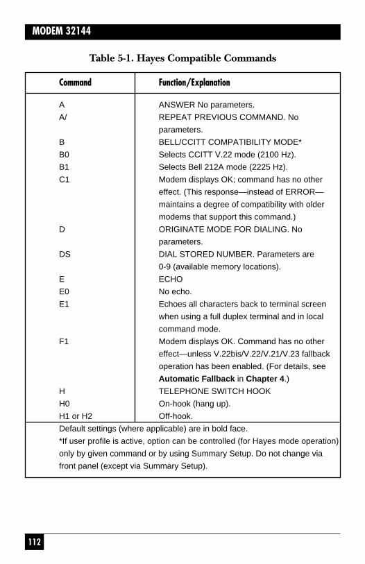
112
MODEM 32144
Table 5-1. Hayes Compatible Commands
Command Function/Explanation
A ANSWER No parameters.
A/ REPEAT PREVIOUS COMMAND. No
parameters.
B BELL/CCITT COMPATIBILITY MODE*
B0 Selects CCITT V.22 mode (2100 Hz).
B1 Selects Bell 212A mode (2225 Hz).
C1 Modem displays OK; command has no other
effect. (This response—instead of ERROR—
maintains a degree of compatibility with older
modems that support this command.)
D ORIGINATE MODE FOR DIALING. No
parameters.
DS DIAL STORED NUMBER. Parameters are
0-9 (available memory locations).
E ECHO
E0 No echo.
E1 Echoes all characters back to terminal screen
when using a full duplex terminal and in local
command mode.
F1 Modem displays OK. Command has no other
effect—unless V.22bis/V.22/V.21/V.23 fallback
operation has been enabled. (For details, see
Automatic Fallback in Chapter 4.)
H TELEPHONE SWITCH HOOK
H0 On-hook (hang up).
H1 or H2 Off-hook.
Default settings (where applicable) are in bold face.
*If user profile is active, option can be controlled (for Hayes mode operation)
only by given command or by using Summary Setup. Do not change via
front panel (except via Summary Setup).

113
CHAPTER 5: Hayes Emulation Mode
Table 5-1. Hayes Compatible Commands (continued)
Command Function/Explanation
I PRODUCT CODE OR CHECKSUM
I0 Requests product code.
I1 Requests checksum for the modem’s software.
(Only a portion of the checksum displayed via
the front panel will be displayed, in decimal
format.)
I2 Requests verification of software checksum.
I3 Requests the following for each EPROM
(programmable memory unit): chip, part and
revision number; checksum.
I4 Reserved.
L SPEAKER VOLUME*
L0 or L1 Low speaker volume.
L2 Medium volume.
L3 High volume.
M SPEAKER CONTROL*
M0 Speaker always OFF.
M1 Speaker ON until carrier is detected.
M2 Speaker always ON.
M3 Speaker OFF during dialing; otherwise ON
until carrier is detected.
O FORCED ON-LINE. Forces modem to on-line
state.
P PULSE DIAL. No parameters, but the default
is T (for tone dial).
Q SEND RESULT CODE
Q0 Send result codes.
Q1 Withhold result codes (quiet).
Q2 Withhold result codes for incoming calls only
(quiet answer).

114
MODEM 32144
Table 5-1. Hayes Compatible Commands (continued)
Command Function/Explanation
Sn=v MODIFY S REGISTER. n is the register to be
modified; v is the value to be written.
Sn? READ S REGISTER. n is the register to be
read.
T TONE DIAL. No parameters.
V WORD/DIGIT RESULT CODE
V0 Result codes are transmitted as digits.
V1 Result codes are transmitted as words.
W WAIT FOR DIAL TONE No parameters, but
default wait time (register S7) is 30 seconds.
X SELECT RESULT CODE
X0 Selects basic result codes, 0-4.
Modem will blind dial (without dial tone).
X1 No speed indication; no busy or dial tone detect.
X2 Selects result codes 0-6, 10, 11, 13, 14, 15, and
18.
X3 Same as X1 except busy signal detect is
enabled. Selects result codes 0-5, 7, 10, 11,
13, 14, 15, and 18.
X4 Same as X1 except busy signal detect is
enabled. Selects all result codes. Connection
speed (up to 14,400 bps) indicated; busy
signal and dial tone detect enabled.
Note: Result code 8 is independent of the X
command; it is displayed only when the @ dial
modifier is used.
Y LONG SPACE DISCONNECT*
Y0 Disables long space disconnect.
Y1 Enables long space disconnect.
Z RECALL STORED USER PROFILE
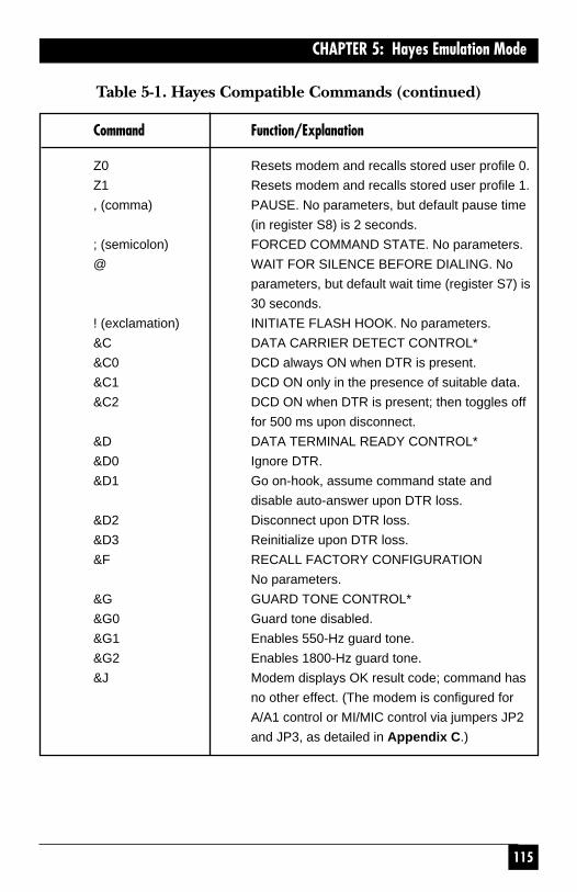
115
CHAPTER 5: Hayes Emulation Mode
Table 5-1. Hayes Compatible Commands (continued)
Command Function/Explanation
Z0 Resets modem and recalls stored user profile 0.
Z1 Resets modem and recalls stored user profile 1.
, (comma) PAUSE. No parameters, but default pause time
(in register S8) is 2 seconds.
; (semicolon) FORCED COMMAND STATE. No parameters.
@ WAIT FOR SILENCE BEFORE DIALING. No
parameters, but default wait time (register S7) is
30 seconds.
! (exclamation) INITIATE FLASH HOOK. No parameters.
&C DATA CARRIER DETECT CONTROL*
&C0 DCD always ON when DTR is present.
&C1 DCD ON only in the presence of suitable data.
&C2 DCD ON when DTR is present; then toggles off
for 500 ms upon disconnect.
&D DATA TERMINAL READY CONTROL*
&D0 Ignore DTR.
&D1 Go on-hook, assume command state and
disable auto-answer upon DTR loss.
&D2 Disconnect upon DTR loss.
&D3 Reinitialize upon DTR loss.
&F RECALL FACTORY CONFIGURATION
No parameters.
&G GUARD TONE CONTROL*
&G0 Guard tone disabled.
&G1 Enables 550-Hz guard tone.
&G2 Enables 1800-Hz guard tone.
&J Modem displays OK result code; command has
no other effect. (The modem is configured for
A/A1 control or MI/MIC control via jumpers JP2
and JP3, as detailed in Appendix C.)

116
MODEM 32144
Table 5-1. Hayes Compatible Commands (continued)
Command Function/Explanation
&L Modem displays OK result code; command has
no other effect. (The modem is configured for
leased line or dialup line operation via the
front-panel QUICK SETUP and/or LINE TYPE
screens.)
&M Can be substituted for &Q.
&P Modem displays OK result code; command has
no other effect. (The pulse dialing ratio is
factory-set, depending on whether the modem
is a US or international model.)
&Q ASYNCHRONOUS/SYNCHRONOUS MODE
&Q0 Asynchronous mode.
&Q1 Synchronous mode 1—
Synchronous/asynchronous mode.
&Q2 Synchronous mode 2—OFF-to-ON DTR
causes the modem to automatically dial a
stored number.
&Q3 Synchronous mode 3—Synchronous mode with
manual dial. (A manually dialed call will switch
immediately to synchronous mode.)
&R RTS AND CTS OPTIONS*
&R0 CTS follows RTS.
&R1 CTS follows DTR from the DTE.
&R2 CTS is on while the modem is on-line.
&S DATA SET READY CONTROL*
&S0 DSR always on.
&S1 DSR operates on according to RS-232
specification.
&S2 Options DSR operation for a crossover
connection.
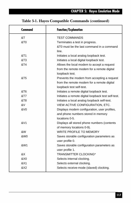
117
CHAPTER 5: Hayes Emulation Mode
Table 5-1. Hayes Compatible Commands (continued)
Command Function/Explanation
&T TEST COMMANDS
&T0 Terminates a test in progress.
&T0 must be the last command in a command
line.
&T1 Initiates a local analog loopback test.
&T3 Initiates a local digital loopback test.
&T4 Allows the local modem to accept a request
from the remote modem for a remote digital
loopback test.
&T5 Prevents the modem from accepting a request
from the remote modem for a remote digital
loopback test self-test.
&T6 Initiates a remote digital loopback test.
&T7 Initiates a remote digital loopback test self-test.
&T8 Initiates a local analog loopback self-test.
&V VIEW ACTIVE CONFIGURATION, ETC.
&V0 Displays modem configuration, user profiles,
and phone numbers stored in memory
locations 0-5.
&V1 Displays all stored phone numbers (contents
of memory locations 0-9).
&W WRITE PROFILE TO MEMORY
&W0 Saves storable configuration parameters as
user profile 0.
&W1 Saves storable configuration parameters as
user profile 1.
&X TRANSMITTER CLOCKING*
&X0 Selects internal clocking.
&X1 Selects external clocking.
&X2 Selects receive-mode (slaved) clocking.
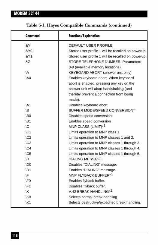
118
MODEM 32144
Table 5-1. Hayes Compatible Commands (continued)
Command Function/Explanation
&Y DEFAULT USER PROFILE
&Y0 Stored user profile 1 will be recalled on powerup.
&Y1 Stored user profile 1 will be recalled on powerup.
&Z STORE TELEPHONE NUMBER. Parameters
0-9 (available memory locations).
\A KEYBOARD ABORT (answer unit only)
\A0 Enables keyboard abort. When keyboard
abort is enabled, pressing any key on the
answer unit will abort handshaking (and
thereby prevent a connection from being
made).
\A1 Disables keyboard abort.
\B BUFFER MODE/SPEED CONVERSION*1
\B0 Disables speed conversion.
\B1 Enables speed conversion
\C MNP CLASS (LIMIT)*1
\C1 Limits operation to MNP class 1.
\C2 Limits operation to MNP classes 1 and 2.
\C3 Limits operation to MNP classes 1 through 3.
\C4 Limits operation to MNP classes 1 through 4.
\C5 Limits operation to MNP classes 1 through 5.
\D DIALING MESSAGE
\D0 Disables ”DIALING” message.
\D1 Enables “DIALING” message.
\F MNP FLYBACK BUFFER*1
\F0 Enables flyback buffer.
\F1 Disables flyback buffer.
\K V.42 BREAK HANDLING*1
\K0 Selects normal break handling.
\K1 Selects destructive/expedited break handling.
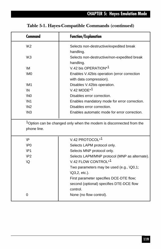
119
CHAPTER 5: Hayes Emulation Mode
Table 5-1. Hayes-Compatible Commands (continued)
Command Function/Explanation
\K2 Selects non-destructive/expedited break
handling.
\K3 Selects non-destructive/non-expedited break
handling.
\M V.42 bis OPERATION*1
\M0 Enables V.42bis operation (error correction
with data compression).
\M1 Disables V.42bis operation.
\N V.42 MODE*1
\N0 Disables error correction.
\N1 Enables mandatory mode for error correction.
\N2 Disables error correction.
\N3 Enables automatic mode for error correction.
1Option can be changed only when the modem is disconnected from the
phone line.
\P V.42 PROTOCOL*1
\P0 Selects LAPM protocol only.
\P1 Selects MNP protocol only.
\P2 Selects LAPM/MNP protocol (MNP as alternate).
\Q V.42 FLOW CONTROL*1
Two parameters may be used (e.g., \Q0,1;
\Q3,2, etc.).
First parameter specifies DCE-DTE flow;
second (optional) specifies DTE-DCE flow
control.
0 None (no flow control).

120
MODEM 32144
Table 5-1. Hayes-Compatible Commands (continued)NOTE: DTE speed and parity are set automatically. Auto-answer is enabled or
disabled by S register S0.
Command Function/Explanation
1 CTS on/off or RTS on/off (CTS for DCE-DTE
flow control, RTS for DTE-DCE).
2 DC1/DC2 flow control.
3 DC1/DC3 flow control (default for DCE-DTE
and DTE-DCE).
%E0 Disables auto-retrain.
%E1 Enables auto-retrain.
-L0 Selects permissive transmit level.
-L1 Selects programmable transmit level.
\S VIEW STATUS OF V.42-RELATED
CONFIGURATION. No parameters.
\T LOAD INACTIVITY TIMER
\T0 Disables inactivity timer.
\Tn Sets inactivity timer to n minutes (where n=0
to 60).
\V V.42 RESULT CODES1
\V0 Activates regular V.42 result codes.
\V1 Activates extended V.42 result codes.
%V0 Switches from Hayes mode to V.25bis mode,
asynchronous.
%V1 Switches to V.25bis mode, sync bit oriented
(HDLC).
%V2 Switches to V.25bis mode, synchronous
character oriented.
\X V.42 PASS-THROUGH FLOW CONTROL*1
\X0 Enables pass-through flow control.
\X1 Disables pass-through flow control.

121
CHAPTER 5: Hayes Emulation Mode
Table 5-2. Hayes Mode Result Codes
Digit code Word code Meaning
0 OK Command line executed without errors
1 CONNECT Carrier detected at 0-300, 1200, or
2400 bps (basic code set)
2 RING Ringing signal detected (in answer
mode). (When the modem detects
a ring, it sends a RING result code
unless it is in the process of accepting
a command. However, the modem
will answer the call only if it is set for
automatic answer or is given an A
command.)
3 NO CARRIER Carrier lost or never detected.
4 ERROR Error in command line, invalid
command, command line exceeds 40
characters, or invalid character format.
5 CONNECT 1200 Carrier detected at 1200 bps.
6 NO DIALTONE No dial tone detected.
7 BUSY Busy signal detected.
8 NO ANSWER No period of silence detected. This
code will appear only if @ (“wait for
silence before dialing”) has been
included in the dial string.
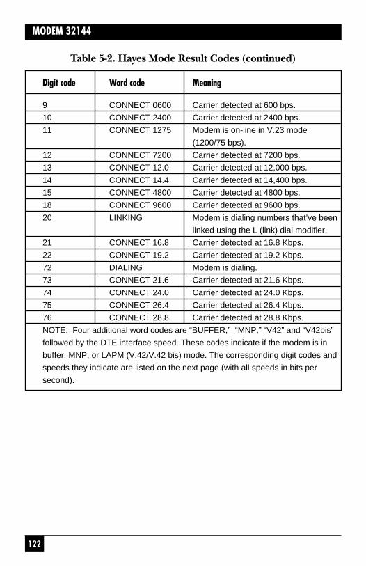
122
MODEM 32144
Table 5-2. Hayes Mode Result Codes (continued)
Digit code Word code Meaning
9 CONNECT 0600 Carrier detected at 600 bps.
10 CONNECT 2400 Carrier detected at 2400 bps.
11 CONNECT 1275 Modem is on-line in V.23 mode
(1200/75 bps).
12 CONNECT 7200 Carrier detected at 7200 bps.
13 CONNECT 12.0 Carrier detected at 12,000 bps.
14 CONNECT 14.4 Carrier detected at 14,400 bps.
15 CONNECT 4800 Carrier detected at 4800 bps.
18 CONNECT 9600 Carrier detected at 9600 bps.
20 LINKING Modem is dialing numbers that’ve been
linked using the L (link) dial modifier.
21 CONNECT 16.8 Carrier detected at 16.8 Kbps.
22 CONNECT 19.2 Carrier detected at 19.2 Kbps.
72 DIALING Modem is dialing.
73 CONNECT 21.6 Carrier detected at 21.6 Kbps.
74 CONNECT 24.0 Carrier detected at 24.0 Kbps.
75 CONNECT 26.4 Carrier detected at 26.4 Kbps.
76 CONNECT 28.8 Carrier detected at 28.8 Kbps.
NOTE: Four additional word codes are “BUFFER,” “MNP,” “V42” and “V42bis”
followed by the DTE interface speed. These codes indicate if the modem is in
buffer, MNP, or LAPM (V.42/V.42 bis) mode. The corresponding digit codes and
speeds they indicate are listed on the next page (with all speeds in bits per
second).

123
CHAPTER 5: Hayes Emulation Mode
Table 5-2. Hayes Mode Result Codes (continued)
BUFFER MNP V42 V42bis
28-19200 36-19200 44-19200 55-38400
29-9600 37-9600 45-9600 56-19200
30-4800 38-4800 46-4800 57-9600
31-2400 39-2400 47-2400 58-4800
32-1200 40-1200 48-1200 59-2400
33-600 41-600 49-600 60-1200
34-300 42-300 50-300 61-600
35-110 43-100 51-110 62-300
53-38400 54-38400 52-38400 63-110
64-57600 65-57600 66-57600 67-57600
68-1800 69-1800 70-1800 71-1800
77-115200 78-115200 79-115200 80-115200
82-230400 83-230400 84-230400 85-230400

124
MODEM 32144
Table 5-3. S Register Functions (only registers intended for useraccess are listed)
Register Range Units Default Description
S0 0-255 rings 1 Ring to answer on
S1 0-255 rings 0 Counts the number of
rings
S2 0-127 ASCII 43 Escape code character
S3 0-127 ASCII 13 Carriage return character
S4 0-127 ASCII 10 Line feed character
S5 0-127 ASCII 8 Backspace character

125
CHAPTER 5: Hayes Emulation Mode
Table 5-3. S Register Functions (only registers intended for useraccess are listed)
S6 2-255 sec 2 Wait time before blind
dialing
S7 1-60 sec 30 Wait time for carrier or
dial tone
S8 0-255 sec 2 Pause time for comma
S9 1-255 sec 6 Carrier detect response
time
S10 1-255 1/10 sec 14 Delay time between
loss of carrier and
“hang-up”
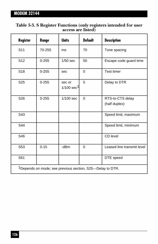
126
MODEM 32144
Table 5-3. S Register Functions (only registers intended for useraccess are listed)
Register Range Units Default Description
S11 70-255 ms 70 Tone spacing
S12 0-255 1/50 sec 50 Escape code guard time
S18 0-255 sec 0 Test timer
S25 0-255 sec or 5 Delay to DTR
1/100 sec1
S26 0-255 1/100 sec 0 RTS-to-CTS delay
(half duplex)
S43 Speed limit, maximum
S44 Speed limit, minimum
S46 CD level
S53 0-15 -dBm 0 Leased line transmit level
S61 DTE speed
1Depends on mode; see previous section, S25—Delay to DTR.

75
CHAPTER 4: General Operation and Special Features
The number stored via thePHONE screen is stored in phonecell 0 (zero). To autodial the front-panel phone number in Hayes orV.25bis mode, specify phone cell 0.
4.2.2 HOW TO STORE A PHONENUMBER
To store a phone number using themodem’s front panel controls,select PHONE from MODEMSETUPS screen 5. The followingscreen will be displayed:
• Use the right and left arrowpushbuttons to go to theposition on the LCD where youwant to enter or change anumber or character. Thenumber or character at thecurrent cursor location flasheson and off.
• Use pushbutton 1 to decrease anumber at the current cursorlocation or pushbutton 3 toincrease a number.
• Use pushbutton 2 (CTRL) tocycle through the dialingcontrol characters. The dialingcontrol characters are listed inTable 4-1, in the order in whichthey appear on the LCD if youcycle through them. Dialingcontrol characters can be savedwith a phone number toperform the functions listed inTable 4-1 when the number isdialed.
The phone number is savedwhen you return to the MAINMENU.
- - - - - - - - - - - - - - - - - - - - - - - - - - - -DEC CTRL INC
If a number has been previouslystored, the number will bedisplayed on the top line of theLCD (instead of dashes, as shownabove). Only one phone number—24 characters maximum—can bestored via the front panel.
Enter the number to be stored byusing the front-panel pushbuttonsas follows:

76
MODEM 32144
Table 4-1. Dialing Control Characters(for use with front-panel PHONE screen)
Character Function
(space) Used only for clarity.
(comma) Effects 2-second pause.
W (or colon) Wait 30 seconds for dial tone before
proceeding.
P Sets pulse dialing mode.
T Sets tone dialing mode.
* Dial * (tone dialing only).
# Dial # (tone dialing only).
/ (diagonal) Prefix required for use with R (/R).
A-D Used in some PBX applications (tone dialing
only).
R Configures modem for Dial Line Auto-
Recovery. Requires / prefix. See Dial Line
Auto-Recovery section later in this chapter.
. (period) Marks end of phone number.
L Links a phone number to another number to
be dialed as an alternate. See L—LINK in
Section 5.4.
: (colon, or W) Wait 30 seconds for dial tone before
proceeding.
- (dash) Used only for clarity (no function).
NOTES: A, B, C, and D are used in some private branch exchange (PBX)
applications. The * and # symbols are sometimes used for access to remote
computer systems.
77
CHAPTER 4: General Operation and Special Features
4.3 Automatic FallbackThe modem incorporates threeautomatic fallback features that canbe controlled by the user:
• Operating-Mode Fallback—Provides compatibility withmodes that use any of severaldifferent operating modes.
• Two options for automatic datarate adjustment: RateRenegotiation Procedure(RRP) and Speed Fallback—These features allow themodem to automatically selectthe highest possible data rate,depending on the signalquality.
4.3.1 OPERATING-MODE FALLBACK
This section applies to dial-lineoperation only.
When the modem originates oranswers a call, it determines fromthe “handshake” routine with theother modem the most efficientoperating mode that is supportedby the other modem andautomatically “falls back” to thatmode. The modem supports twoalternatives for operating-modefallback: V.22 bis/Bell 212A/Bell103 fallback operation (defaultsetting) and V.22bis/V.22/V.21/V.23 fallbackoperation. Operating-modefallback functions when themodem is in either manual orautomatic originate mode ormanual or automatic answer mode.
For communication within theUnited States, use the defaultsetting for Operating-ModeFallback—V.22bis/Bell 212A/Bell103.
V.22 bis/V.22/V.21/V.23 FallbackOperation
To configure the modem for V.22bis/V.22/V.21/V.23 fallbackoperation, refer to Appendix B,Fig. B-7. Change the OperatingMode Fallback parameter shown inthe diagram from 0 (the factorysetting) to 1. (This is the only waythe Operating Mode Fallbacksetting can be changed.)
Changing the Operating ModeFallback parameter to 1 has thefollowing effects:
• The modem will be configuredfor V.22 bis 2400-bps/V.221200- and 600-bps/V.21 300-bps/V.23 1200/75 bps fallbackoperation. As a result, 600 and1200/75 bps will appear asadditional selections on theSPEED LIMIT LCD screens.
• Fallback to V.22 bis Bell 212Aand Bell 103 compatibility isdisabled.
• An AT command is available (inHayes mode only) that allowscontrol over operating mode asfollows: F0—Multi-modeoperation (default); F1—V.21,300 bps; F2—V.22, 600 bps;F3—V.23, 1200/75 bps; F4—

78
MODEM 32144
V.22, 1200 bps; F5—V.22bis,2400 bps; F6—V.32 (highestcommon speed). Except formulti-mode operation, themode and speed are limited tothe mode and speed specified.Multi-mode operation allowsthe modem to automatically fallback to the most efficient modethat can be used by bothmodems.
Available Fallback Modes
The preferred mode is V.32/V.32bis (4800 bps or higher,asynchronous/synchronous, fullduplex); however, if the othermodem does not support V.32 orV.32 bis, the modem will fall backto one of the modes listed below.The fallback modes are listed in theorder in which they are attemptedby the modem in normaloperation:
Table 4-2. V.22 bis/Bell 212A/Bell 103 Fallback (Default)
Mode Description
V.22 bis 2400 bps asynchronous/synchronous
Bell 212A 1200 bps asynchronous/synchronous
Bell 103 0-300 bps asynchronous
All modes are full duplex.
If V.22 bis/V.22/V.21/V.23fallback operation is enabled, thefollowing fallback modes areavailable. As in the previous list, themodes are listed in the order inwhich they are attempted by themodem.
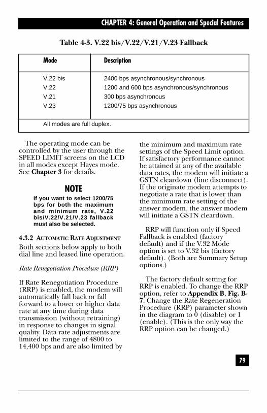
79
CHAPTER 4: General Operation and Special Features
Table 4-3. V.22 bis/V.22/V.21/V.23 Fallback
Mode Description
V.22 bis 2400 bps asynchronous/synchronous
V.22 1200 and 600 bps asynchronous/synchronous
V.21 300 bps asynchronous
V.23 1200/75 bps asynchronous
All modes are full duplex.
the minimum and maximum ratesettings of the Speed Limit option.If satisfactory performance cannotbe attained at any of the availabledata rates, the modem will initiate aGSTN cleardown (line disconnect).If the originate modem attempts tonegotiate a rate that is lower thanthe minimum rate setting of theanswer modem, the answer modemwill initiate a GSTN cleardown.
RRP will function only if SpeedFallback is enabled (factorydefault) and if the V.32 Modeoption is set to V.32 bis (factorydefault). (Both are Summary Setupoptions.)
The factory default setting forRRP is enabled. To change the RRPoption, refer to Appendix B, Fig. B-7. Change the Rate RegenerationProcedure (RRP) parameter shownin the diagram to 0 (disable) or 1(enable). (This is the only way theRRP option can be changed.)
The operating mode can becontrolled by the user through theSPEED LIMIT screens on the LCDin all modes except Hayes mode.See Chapter 3 for details.
NOTEIf you want to select 1200/75bps for both the maximumand minimum rate, V.22bis/V.22/V.21/V.23 fallbackmust also be selected.
4.3.2 AUTOMATIC RATE ADJUSTMENT
Both sections below apply to bothdial line and leased line operation.
Rate Renegotiation Procedure (RRP)
If Rate Renegotiation Procedure(RRP) is enabled, the modem willautomatically fall back or fallforward to a lower or higher datarate at any time during datatransmission (without retraining)in response to changes in signalquality. Data rate adjustments arelimited to the range of 4800 to14,400 bps and are also limited by

80
MODEM 32144
4.4 Dumb Mode and Bell 208OperationTable 4-3 lists dialing parametersthat may be used to modify Dumbmode or Bell 208 dialingoperations.
4.4.1 MANUAL ORIGINATE/ANSWEROPERATION
When the modem is operating inDumb mode or configured for Bell208 operation, data calls may bemanually originated from a phoneset. (Plug the phone into themodem jack marked “PHONE.”)
For manual-originate operation,the remote modem may beconfigured for either automatic ormanual answer. For manual-originate/answer operation, onemodem must be set to ANSWERand one must be set toORIGINATE via the ANS/ORGDEFAULT screen. For either typeof operation, use the Quick Setupto configure the modem. (TheDumb mode Quick Setup defaultsto asynchronous operation; the Bell208 and V.32/208 Quick Setupsdefault to synchronous operation.)
Any of these three Quick Setupswill set the modem to originatemode. If you want to set yourmodem to answer mode, use thefront panel controls to access theANS/ORG DEFAULT screen(MODEM SETUPS screen 4). Thenselect ANSWER (answer mode).
Originating a Data Call Manually
To manually originate a data call,select TALK from MAIN MENUscreen 1. The MANUAL-DIALscreen will now be displayed. SelectTALK again. This puts the modemin talk mode. Lift the handset andlisten for the dial tone. Dial thephone number of the remotemodem.
When you hear a high-pitchedanswer tone, select DATA from theMANUAL-DIAL screen, and placethe handset back on the cradle.The LCD will display the status ofthe communication. Typically it willappear as follows:
D TR MR RS CS9600 CD
The data link between the twomodems is now established, anddata transfer can begin.

81
CHAPTER 4: General Operation and Special Features
Answering a Data Call Manually
An incoming call may be answeredmanually or automatically,although to answer a data callmanually, the Auto-Answer optionmust be disabled. Before the call isreceived, the modem must be set toTALK, as explained in the previoussection. The unit that will beswitched to DATA mode first mustbe set for answer mode (using theanswer/originate option). Theother unit must be set for originatemode.
NOTEIf you set the modem to talkmode, the phone will ring,but the modem will notanswer, even if the Auto-Answer option is enabled.
After the phone has rung, andyou have answered it, the modemmust be set for data mode: Withthe MANUAL-DIAL screen stilldisplayed, select DATA. This putsthe modem in data mode.
The first person to go to datamode will hear his telephonedisconnect as his modem connects.The other person must wait untilhe hears an answer tone, and thenswitch to data mode (select DATA).When both modems are in datamode, the data communication willbegin. The LCD will display thestatus of the connection.
Terminating a Data Call
There are several ways a data callcan be terminated. One way isthrough communicationsoftware—by following the softwaremanufacturer’s instructions. Analternate method is to switch to theTALK option (talk mode) on theMANUAL-DIAL screen, asdescribed in the previous section.Another method is to drop theDTR signal from the DTE (bysoftware control or by turning theDTE off).
4.5 V.32/208 Auto-Detect ModeWhen V.32/208 auto-detect modeis enabled, the modem willautomatically select either V.32(V.32/V.32 bis) or Bell 208operation. These two types ofoperation are described below.
4.5.1 V.32/V.32 BIS OPERATION
In V.32/208 auto-detect mode, ananswering modem will, upondetection of a V.32 handshake,operate with the following optionsset as shown:
• Data format—synchronous
• V.13 operation—TX and RX
• Carrier type—constant
• CTS to EIA—RTS (CTS followsRTS)
82
MODEM 32144
4.5.2 BELL 208 OPERATION
In V.32/208 auto-detect mode, ananswering modem will, upondetection of an originating Bell208B modem, operate with thefollowing options set as shown:
• Data format—synchronous
• V.13 operation—off
• Carrier type—switched
The originating Bell 208 modemmust be configured to detect theBell 208 answer tone before it goesto data mode. (Some 208 modemsmay not have this option.)
4.5.3 AUTOMATIC FALLBACK
When the modem is configured forV.32/208 auto-select mode and inanswer mode, it will not handshakein V.22 bis, Bell 212/103 orV.21/V.22, V.23 mode.
4.6 V.13 OperationThe modem can be configured forCCITT V.13 operation (whichemulates half duplex operation)for either point-to-point ormultidrop applications. (Thecorrect options for theseapplications are identified inChapter 3.) The modem normallyoperates in full duplex; however,some applications (such as certainnetwork environments) mayrequire control of a remote CDsignal by a local Request to Send(RTS) signal. V.13 operation allows
local RTS control of a remote CDsignal without actual ON-OFFswitching of the modem carrier.
The following explains how themodem will respond to RTS signalswhen it is configured for V.13operation:
When RTS is raised high by theterminal, the V.13 ON PATTERNwill be sent. The modem will thenraise CTS (and data can be sent).When RTS is brought low, the V.13IDLE PATTERN will be sent, andthe modem will drop CTS. (If V.13TX is enabled but the modem datapump is not ready to send, forexample, if it is training orretraining, raising RTS will causeCTS to be raised, but the V.13 ONPATTERN will not be sent.) WhenV.13 RX is enabled, CD will turnON if the V.13 ON PATTERN isdetected; CD will turn OFF if theV.13 IDLE PATTERN is detected orif the modem retrains, loses carrier,or is reset.
4.7 DTR Dialing
NOTETo use DTR dialing in V.25bis or Penril mode, you mustuse the Summary Setupfeature, as explained inChapters 6 (V.25 bis) and 7(Penril).

83
CHAPTER 4: General Operation and Special Features
4.7.1 DIALING A STORED NUMBER
DTR dialing allows you to set upthe modem to automatically dial astored number even when theautodialer has not been enabled.
To enable DTR dialing, selectDTR from the DIALER optionscreen.
When DTR dialing is enabled, anOFF-to-ON transition of DTR willcause the modem to automaticallydial the number previously storedusing the front panel LCD. DTRmust remain on for at least 50 msto effect automatic dialing. A 50-msdrop of DTR will abort the processor disconnect the call. When DTRgoes high again for at least 50 ms,the automatic dialing process willbegin again.
4.7.2 ANSWER MODE OPERATION
If the modem is set for DTRdialing, it will automatically answerwithout DTR. However, it will notbe able to transfer data until DTRgoes high. The call may beterminated by dropping DTR.
4.8 Dial Line Auto-RecoveryThe Dial Line Auto-Recoveryfeature allows you to setup themodem for a dial-up application soit will automatically redial torestore a broken connection if themodem goes on-hook. In this way,the Dial Line Auto-Recoveryfeature emulates the reliability of aleased line connection.
4.8.1 SETTING UP THE MODEM FORDIAL LINE AUTO-RECOVERY
Two steps are required to set up themodem for Dial Line Auto-Recovery: You must first enter orstore the number to be dialedtogether with the /R command;then you must enable Dial LineAuto-Recovery.
Entering the /R Command
To configure the modem for DialLine Auto-Recovery from the frontpanel, enter the phone number tobe dialed followed by /R (the DialLine Auto-Recovery command) onthe PHONE screen:
T555-4545/RDEC CTRL INC
If you need assistance, seeSection 4.2, Storing PhoneNumbers.
An alternate way to configure themodem for Dial Line Auto-Recovery (in Hayes mode only) isto use the Hayes AT &Z commandto store the phone number to beredialed and the /R command inmemory location 0, by entering
AT &Z0=T555=4545/R
84
MODEM 32144
Enabling Dial Line Auto-Recovery
Dial Line Auto-Recovery will not beactive until you select DIAL fromthe front panel AUTO-DIAL screen(or, in Hayes mode, use thecommand AT DS=0—or, in V.25 bismode, use the command CRS 0). Ifpower is removed from themodem, you will have to re-enableDial Line Auto-Recovery. To disableDial Line Auto-Recovery, selectRESET from MAIN MENU screen3.
4.8.2 RECOVERY PROCEDURE
If Dial Line Auto-Recovery isenabled and the modem goes on-hook, it will redial the storedphone number up to 10 times. Itwill redial 5 times at 30-secondintervals, wait 2 hours, and thenredial 5 additional times at 30-second intervals. The modem stopsredialing after 10 attempts.
If a connection has been brokenand re-established and is thenbroken again, the full sequence of10 redial attempts will not occurunless the modem has been on-linefor more than 1 hour. The modemwill redial, but it is programmednot to exceed more than 10 redialattempts in 1 hour.
4.9 Leased Line Auto-RecoveryThe Leased Line Auto-Recoveryfeature allows the modem toautomatically restore operation fora leased line application by usingdial lines as a backup whenconditions on the leased linesdeteriorate. The modem usessignal quality and loss of carrierdetect to determine if lineconditions are unsatisfactory.Leased Line Auto-Recovery isaccessed via the AUTO-RECOVERYscreen on the front-panel LCD.
The following conditions arerequired for Leased Line Auto-Recovery operation:
• Leased Line Auto-Recoverymust be enabled (using theLeased Line Auto-RecoverySelect option) on bothcommunicating modems.
• The Leased Line Auto-RecoverySelect, Return, and Test optionsmust be set correctly on bothcommunicating modems, asexplained in the followingsections.
• A dial backup line (or lines)must be installed.
• The phone number to be dialed(the backup line) must bestored in the originate modem,as explained in the previoussection.
• Auto-answer must be enabledon the answer modem.

85
CHAPTER 4: General Operation and Special Features
4.9.1 AUTODIAL BACKUP
The modem will automatically dialthe stored number to connect overthe backup line if it detects poorsignal quality (ER) or a loss ofcarrier detect (CD) on the leasedline. The criteria used by themodem in assessing the conditionof the leased line depend upon thesettings of the Signal Qualityoption (one error in 103 or 105 bits)and the Carrier Detect Leveloption (-43, 33, or -26 dBm).
Dial Backup Message
When dial backup occurs (eitherautomatically or by operatorintervention), the followingmessage will flash on the frontpanel LCD of both modems:
4.9.2 EXIT FROM LEASED LINE AUTO-RECOVERY
If the Leased Line Auto-RecoveryReturn option is enabled (seebelow, the modem willautomatically exit the Auto-Recovery mode when the leasedline conditions are satisfactory. Anynormal disconnects (such as loss ofcarrier or line current) may alsodisconnect the dial connectionsand return communication to theleased line.
To ensure the proper disconnectcapabilities for Leased Line AutoRecovery mode, both of thefollowing disconnect options mustbe enabled on both modems: linecurrent disconnect (CURRENTDISC’T screen) and carrierdisconnect (CARRIER DISC’T).
To manually exit the Leased LineAuto-Recovery mode and return toleased-line operation, select DIALfrom MAIN MENU screen 1, andthen select HANGUP for theAUTO-DIAL screen.
ATTENTION:DIAL BACKUP
This message will clear when themodem returns to the leased line.If you want to clear the messagewhile the modem is still in dial-backup mode, press the ENTpushbutton.

86
MODEM 32144
Manual Recovery
If both modems are set forMANUAL RECOVERY, theoriginate unit can be used toautodial the number stored via thePHONE screen without having tochange the LINE TYPE setting oneither unit. To autodial, access theAUTO-DIAL screen and selectDIAL. To return to the leased line,select HANGUP from the AUTO-DIAL screen.
Return from Leased Line Auto-Recovery(RETN)
This option determines the criteriafor exiting Leased Line Auto-Recovery mode.
“RETURN IF GOOD>(10, 40, 60,or 120)s” means the modem willautomatically exit the Leased LineAuto-Recovery mode when it testsand finds the leased line in goodcondition for more than the timeperiod specified (10, 40, 60, or 120s). If the Return option is set toOFF, the modem will stay in theAuto-Recovery mode indefinitely,unless you select HANGUP fromthe AUTO-DIAL screen or unless aloss of line current or other normaldisconnect occurs. Either event willreturn communication to theleased line.
NOTEThe Return option settingmust be the same on bothcommunicating units.
4.9.3 LEASED LINE AUTO-RECOVERYOPTIONS
Three options allow you to specifythe criteria the modem will use indetermining when to enter andexit the Leased Line Auto-Recoverymode:
Leased Line Auto-Recovery Select(Select)
This option determines the type ofLeased Line Auto-Recoverydesired. “DIAL IF BAD>(1, 2, 3, or4) min” or “DIAL IF BAD>30 s(seconds)” means dial backup willoccur if bad line conditions arepresent for the specified (selected)time period. To disable the LeasedLine Auto Recovery, select NOAUTO RECOVERY. A sixth option,Manual Recovery, is discussedbelow.
NOTEIf “DIAL IF BAD>(1, 2, 3, or 44) min (or 30 s)” is selected,the Select option settings ofthe answer and originateunits must be the same.

87
CHAPTER 4: General Operation and Special Features
• Manual-response passwordprotection (MPP). Remoteusers attempting to connect tothe modem are required toenter a password. Incomingcalls are accepted only if theuser enters a valid password.
4.11 Automatic Password Protection(APP)The modem can be configured fortwo types of APP:
• APP without callback—Themodem can be configured sothat each time it receives aconnect request from anothermodem, it automaticallyemploys a security handshakethat includes a user-assignedpassword. Connect requests willbe accepted only from modemsthat have been programmedwith the same password. APPwithout callback functions inany operating mode that usestrellis coding (normally 72, 090bps and above).
• APP with callback—This type ofpassword protection is the sameas described above, except thatthe answer modem connectswith the originating modem bycalling it back. The connectioncan only be made if bothmodems are preprogrammedwith the same password and ifthe answer modem ispreprogrammed with thenumber of the originatingmodem (the callback phonenumber). APP with callback isfor dialup applications only(synchronous orasynchronous).
Test Interval (Test)
If the Return option has beenenabled (10, 40, 60, or 120 s), theTest Interval selections control howfrequently the modem will test theleased line conditions to determineif exit from the Leased Line Auto-Recovery mode is desirable (basedon the criteria selected for returnfrom Auto-Recovery). The modemcan be set to test every 10, 20, 40,or 60 minutes.
NOTEThe Test option setting mustbe the same on both units.
4.10 Modem Security Operation
NOTESecurity features describedin this manual provide adeterrent to unauthorizedaccess. No communicationssystem can be madeperfectly secure.
Two types of security operationare available to screen incomingcalls:
• Automatic password protection(APP). Users do not have toenter a password, but bothmodems must be correctlyconfigured to exchange thesame password (as part of asecurity handshake), or theywill not be able to connect.

88
MODEM 32144
With either type of APP, eachincoming call is password-protected, yet there is no need foruser to enter a password. Passwordsare preprogrammed, sent over themodems’ auxiliary channel, andautomatically compared by themodem. The only time manualintervention is required is when thepassword (and callback number, ifused) is established or changed.
If desired, the password can bedisabled. This allows the modem toaccept calls from modems that havenot been programmed to send thecorrect password—includingmodems that do not support themodem security handshake.
The automatically invokedpassword (and callback number, ifused) is established or changed.
If desired, the password can bedisabled. This allows the modem toaccept calls from modems that havenot been programmed to send thecorrect password—includingmodems that do not support themodem security handshake.
The automatically invokedpassword (and callback phonenumber, if used) is stored innonvolatile memory, so it will bemaintained if the unit loses poweror upon a quick (soft) reset.However, a factory reset will clearthe automatic password (andcallback number, if used) frommemory.
NOTEWhen APP is used, themodem will not fall back tospeeds lower than 7200 bps.
After a connection has beenestablished using the securityhandshake and automatic password(and callback phone number, ifused), a flashing “S” will bedisplayed in the top left corner ofthe EIA status screen to indicatethat a secure connection has beenmade. (If the modem is in a dialmode, “S”—and “D” for dial lineoccupied—will flash alternately.)
The APP process is summarizedbelow. Answer modem refers to thelocal modem; originating modemrefers to a remote modem; when itcalls or attempts to call the answermodem.
• An originating modem calls theanswer modem.
• The originating modemautomatically sends thepreprogrammed password viathe security handshake.
• If the answer modem isconfigured for APP withoutcallback, it confirms thepassword and connects.
For APP without callback, this isthe end of the process. For APPwith callback, the processcontinues:

89
CHAPTER 4: General Operation and Special Features
• Both modems go on-hook.
• The answer modem calls theoriginating modem back.
• Modems exchange securityhandshake (again) andconnect.
4.12 Configuring Modems for APPThe procedures for configuring theoriginating and answer modems forboth types of APP are summarizedbelow and then explained in detailin the subsequent sections.
4.12.1 APP WITHOUT CALLBACK
• Enter the same password in thefront panel password screen(on the LCD) of theoriginating modem and answermodem.
4.12.2 APP WITH CALLBACK
• Enter a password in the frontpanel password screen of theoriginating modem (the userpassword).
• A password must be entered inthe front-panel password screenof the answer modem (the mas-ter password). Any passwordwill do (even a single charac-ter), except that it should notbe the same as the user pass-word, and it should not be the
same as any other passwordstored in the answer modem’smemory (for APP or MPP).APP with callback will not func-tion if the master password isremoved.
• Use the Hayes AT &Z commandto store the user password andcallback phone number in theanswer modem’s memory.
4.12.3 PASSWORD SCREENS
For either type of APP, a passwordmust be preprogrammed throughthe PASSWORD screen of both theanswer and originating modems, asexplained below.
For APP without callback, use thesame password on both modems.For APP with callback, do not usethe same password—see Section4.12.2.
Establishing or Changing theAutomatic Password
The automatic password can bechanged (or initially established)using the front panel passwordscreens shown below. These screensare accessed via the PASSWORDscreen.
Change-Password Screen:
DEC SKIP INC
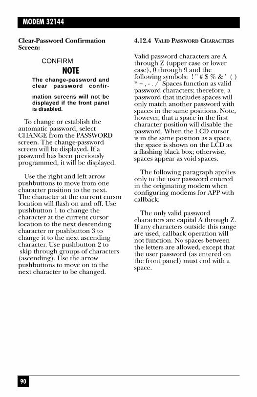
90
MODEM 32144
4.12.4 VALID PASSWORD CHARACTERS
Valid password characters are Athrough Z (upper case or lowercase), 0 through 9 and thefollowing symbols: ! " # $ % & ' ( )* + , - . / Spaces function as validpassword characters; therefore, apassword that includes spaces willonly match another password withspaces in the same positions. Note,however, that a space in the firstcharacter position will disable thepassword. When the LCD cursor is in the same position as a space,the space is shown on the LCD as a flashing black box; otherwise,spaces appear as void spaces.
The following paragraph appliesonly to the user password enteredin the originating modem whenconfiguring modems for APP withcallback:
The only valid passwordcharacters are capital A through Z.If any characters outside this rangeare used, callback operation willnot function. No spaces betweenthe letters are allowed, except thatthe user password (as entered onthe front panel) must end with aspace.
Clear-Password ConfirmationScreen:
CONFIRM
NOTEThe change-password andclear password confir-
mation screens will not bedisplayed if the front panelis disabled.
To change or establish theautomatic password, selectCHANGE from the PASSWORDscreen. The change-passwordscreen will be displayed. If apassword has been previouslyprogrammed, it will be displayed.
Use the right and left arrowpushbuttons to move from onecharacter position to the next. The character at the current cursorlocation will flash on and off. Usepushbutton 1 to change thecharacter at the current cursorlocation to the next descendingcharacter or pushbutton 3 tochange it to the next ascendingcharacter. Use pushbutton 2 toskip through groups of characters(ascending). Use the arrowpushbuttons to move on to thenext character to be changed.

91
CHAPTER 4: General Operation and Special Features
Entering the Selected Password
When the new password is correctlydisplayed on the LCD, press theENT pushbutton. This will causethe new password to take effect.
The modems are configured for APP without callback whenmatching passwords are entered in the front panel password screensof both modems.4.12.5 APP WITH CALLBACK: STORINGTHE PASSWORD WITH CALLBACKNUMBER
If you have followed these instruc-tions to this point, the userpassword will be stored in the front-panel password screen of theoriginating modem, and a differentpassword (the master password)will be stored in the front-panelpassword screen of the originatingmodem, and a different password(the master password) will bestored in the front panel passwordscreen of the answer modem. (Themaster password should bedifferent from the user password,because it can be used to access theanswer modem directly, withoutcallback. The master passwordallows access for troubleshootingfrom a remote site.)
The final step in configuring themodems for APP with callback is to store the user password in theanswer modem’s memory, alongwith the callback phone number, as explained below.
From the DTE, use the Hayes AT&Z command and /S (a specialcommand) to store the userpassword (capital A through Z, nospaces) and callback number in aspecific memory location. Memorylocations 0 through 9 may be used.The following example shows howto store a user password andcallback number in memorylocation 3:
Enter AT &Z3=T5551212/SGRAPE
The callback number (phonenumber of the originating modem)in this example is 555-1212 (with Tused to specify tone dialing). Theuser password is GRAPE. (Whenthe user password is entered on thefront panel password screen of theoriginating modem, a space isrequired at the end. Do not use aspace at the end when storing thepassword with the AT &Zcommand.)
A remote user can now call fromthe specified callback number, 555-1212. The originating modem willsend the preprogrammed passwordGRAPE as part of the securityhandshake. The answer modemwill confirm the password andconnect by calling the originatingmodem back.
4.13 Disabling APP4.13.1 TEMPORARILY DISABLING APPTo temporarily disable either typeof APP, select CHANGE from the
92
MODEM 32144
4.14 Manual-Response PasswordProtection (MPP)The modem can be configured for two types of MPP:
• MPP without callback—Themodem will pass a connectionon to the DTE interface onlyafter it receives a validpassword.
• MPP with callback—The answer modem will call backan authorized user after he or she enters a valid password.
Both types of security operationprovide security on incoming callsby requiring remote user tomanually enter a valid password.In addition, access to Hayes-compatible commands for viewingand storing phone numbers ispassword protected.
The MPP process is summarizedbelow.
• A remote (originating) modemcalls the local (answer) modem.
• Local modem answers.
• Remote user sends carriagereturn [CR].
• Answer modem confirmspassword and grants access (ifprogrammed for MPP withoutcallback) or initiates securitycallback (if programmed forMPP with callback).
PASSWORD screen. The change-password screen will be displayed.With the cursor in the firstcharacter position, presspushbutton 2 (SKIP) until a spaceappears (flashing ■ ). Then pressENT. The password will bedisabled.
With the password disabled, theanswer modem can connect toanother modem that is notequipped to use or is notconfigured to use APP (forexample, one where a password hasnot been entered in the front-panelchange-password screen). However,it will not be able to connect to amodem that is programmed with apassword for APP without callback.To restore the password, replacethe space with the first character of the password and press ENT.
4.13.2 CLEARING THE PASSWORD
To clear the front-panel passwordfrom memory, select CLEAR fromthe PASSWORD screen. The clear-password confirmation screen willbe displayed. Press pushbutton 2 toconfirm that you want to clear thepassword.
If no password is stored, themodem will be able to connect to other modems that are notequipped to use or are notconfigured to use an automaticpassword (APP). To temporarilydisable the automatic password, see the previous section.

93
CHAPTER 4: General Operation and Special Features
4.15 Commands for Enabling MPPModem configuration for MPP iscontrolled from the DTE by aspecial set of password commands.These commands are implementedby using the Hayes AT &Zcommand to store them inmemory. If an administrativepassword has been implemented,the front panel will be disabled andthe AT &Z command will notfunction until it (the AT &Zcommand) is unlocked. (Theprocedure for unlocking the AT&Z command is explained inSection 41.6, How to Use PasswordCommands.
The modem incorporates 10memory locations for storingtelephone numbers, passwords,and/or the MPP passwordcommands listed in Table 4-4. Toimplement a security command,use the Hayes AT &Z command tostore the command in a specificmemory location. The passwordcommands are listed in Table 4-4and explained in detail in thesections that follow.
Table 4-4. Password Commands for MPP.
Command Function Example Mem. loc.
/A Set/change administrative password; /ASECURITY 1
password-protects use of certain
Hayes commands.
/P Set password for— /PYELLOW 2-9
MPP without callback or
MPP with callback 4443535/PRED
/U User-defined text string. Used to /UHELLP 0
send a response to the remote
terminal user after a valid password
is received.
1Command string stored using AT &Z command.2Each command will function only in the listed memory locations.

94
MODEM 32144
Rules for Using Passwords andPassword Commands (MPP)
• Memory locations 0 and 2-9 may be used for storing phonenumbers; locations 2-9 may be used to store passwords.
• The entire command string,including the AT &Zcommand, cannot exceed40 characters.
Passwords
• Passwords and commands may be entered in capitals orlowercase letters. (However,they will be stored andsubsequently displayed ascapitals.) Do not includenumber or spaces.
• For MPP without callback, /must be the first character in astorage location; for MPP withcallback operation, a phonenumber must be listed first in astorage location.
• Special characters (! @ ?, etc.)may be used for passwordsentered via the DTE interface,but these characters cannot beentered via the modem’s frontpanel.
• A phone number cannot bestored after /.
Commands
• Only one command (/A, /P, or /U) can be stored in eachmemory location.
• Do not leave a space after acommand.
• When using the /U command,do not include spaces orcontrol characters in thespecified text string.
4.16 How to Use PasswordCommandsTo Establish or Change theAdministrative Password:
For greatest security, anadministrative password should be used. If implemented, theadministrative password controlsaccess to the Hayes-compatible &Vand &Z commands. Thesecommands are required to view or modify the modem’s securityconfiguration (as explained in the following sections).
To establish or change anadministrative password:
Enter AT &Z1=/ASECURITY
but replace SECURITY with the password of your choice.

95
CHAPTER 4: General Operation and Special Features
NOTEThe administrative pass-word may only be stored inmemory location 1. Thecommand line, including AT&Z1=, cannot exceed 40characters.
To Unlock the &V and &ZCommands:
If an administrative password hasbeen implemented, the Hayes-compatible &V and &Z commandscannot be accessed unless they arefirst unlocked using the currentadministrative password. (&V isused to view the active modemconfiguration, stored phonenumbers, password commands and passwords; &Z is used to store phone numbers, passwordcommands, and passwords). Tounlock the &V and &Z commands,enter
AT &Z=/ASECURITY
or substitute other currentpassword in place of SECURITY.
The &V and &Z commands willnow be accessible.
To re-lock the &V and &Zcommands, enter AT Z. The DTEwill respond with OK, and the &Vor &Z commands will not functionuntil they are unlocked.
To Program MPP without CallbackOperation
Use the commands AT &Z and /Pto specify the password to be usedfor MPP without callbackoperation. The following exampleprograms memory location 5 forMPP without callback:
Enter AT &Z5=/PYELLOW
The password is YELLOW. Afterthe modems connect, the remoteuser presses the DTE Enter keyonce. The DTE will then promptthe user to enter the assignedpassword by displaying thePASSWORD? query. If the userenters the correct password,YELLOW, the call will beconnected.
NOTEMPP Passwords may only bestored in memory locations2 through 9.
To Program MPP with CallbackOperation:
Use the commands AT &Z and /Pto specify the callback phonenumber and password to be used.The following example programsmemory location 3 for callbackoperation:
Enter AT&Z3=T5551212/PCANARY
96
MODEM 32144
To Program a Response to a CorrectPassword:
Enter AT &Z0=/UCONNECTED
but replace CONNECTED withthe message of your choice.
The DTE will respond with the specified message when the modem receives a correctpassword.
NOTEThe /U command andmessage can only be storedin memory location 0.
The callback number in thisexample is 555-1212 (with Tused to specify tone dialing); thepassword is CANARY. A remoteuser can now call from thespecified callback number, 555-1212. After the modems connect,the remote user presses the DTEEnter key once. The DTE will thenprompt the user to enter theassigned password by displaying thePASSWORD? query. Upon receiptof the correct password, CANARY,the local modem will call back theremote user at 555-1212. Once thisconnection is established, data maypass freely.
NOTEMPP passwords and callback numbers may only bestored in memory locations2 through 9.

39
CHAPTER 3: Options: Customizing the Modem Setup
Fig. 3-1. Summary of Pushbutton Control Functions.
If a menu has more than onescreen, each screen is numbered.The screen number is shown in theupper right corner of a screen (seethe sample screen below.) If amenu has no screen number, it hasonly one screen. Additional menuscreens (where present) showadditional option selections.
DISPLAYS PREVIOUSMENU SCREEN
DISPLAYS NEXTMENU SCREEN
EXITS FROMDISPLAYED
SCREEN
1 2 3 ENT
USED TO SELECT CHOICE 1, 2 OR 3 FROM THE LCD
(Each of the possible selections on the bottom lineof the LCD is identified as 1, 2 or 3 below the LCD.)
Arrow Pushbuttons
The left arrow (<--) and right arrow(-->) pushbuttons are used todisplay additional or previousscreens that are part of the samemenu. The right arrow pushbuttondisplays an additional menu screen(if there is one); the left arrowpushbutton displays the previousmenu screen. With respect to howthe LCD flow chart is set up, thearrow pushbuttons “move you”either right or left within the chart.
MAIN MENU <2>SETUP TEST RMT

40
MODEM 32144
Numbered Pushbuttons
Pushbuttons 1, 2, and 3 correspondto segments 1, 2, and 3 of the LCDscreen. These segments (left,middle and right positions of theLCD screen) are numbered on themodem’s front panel. To make aselection from a menu screen,simply push the button with thesame number as the selection you want.
With respect to how the LCDflow chart is organized,pushbuttons 1, 2, and 3 will eithertake you to a lower level—or, wherethere is no route to a lower level,they will select an option.
ENT Pushbutton
To exit from a displayed screen,press the ENT (enter) pushbutton.With respect to how the LCD flowchart is set up, pushing the ENTbutton will move you upwardthrough the chart (toward theMAIN MENU). If you become lost, pressing the ENT buttonrepeatedly will return you to screen1 of the MAIN MENU. PressingENT repeatedly after you havearrived at MAIN MENU screen 1will cause the LCD to alternatebetween the EIA status screen andthe MAIN MENU. (In the case ofmost tests, the ENT button cannotbe used to exit the test screen oncethe test has been activated; youmust first press the ENT buttonand then select OFF to end the test.)
3.3 Selecting Options from the FrontPanel This section applies to all optionscreens on the front panel LCDexcept the Summary Setup screens,which are explained in Appendix B.
Options are accessed from theSETUP menu. As shown in theLCD flow chart, the SETUP menuconsists of six screens and isaccessed from screen 2 of theMAIN MENU. (With screen 2 of the MAIN MENU displayed,push button 1 to select SETUP.)
Once you have located the screenthat displays the option you want toaccess or change, select your choiceby pushing the button with thesame number as the selection youwant. Each selection on the bottomline of the LCD is numbered either1, 2, or 3 on the modem’s frontpanel (not on the LCD), as shownin Fig. 3-2.

41
CHAPTER 3: Options: Customizing the Modem Setup
Fig. 3-2. The Front Panel.
• The option choices you selectare automatically saved by themodem when you leave theSETUP menu.
3.3.1 DEC/INC(DECREASE/INCREASE) SCREENS
Several option screens show theabbreviations DEC and INC on the bottom line of the LCD display.This means that the numericalvalue shown on the top line (e.g.,a stored phone number) can be changed. Selecting DEC(pushbutton 1) will decrease thevalue; selecting INC (pushbutton3) will increase it.
SETUPQUICK LINE SPEED
< 1 >
1 2 3
LCD
Front panel
When an option is first selected,it will flash on and off on the LCD.However, it will not take effect untilyou leave the SETUP menu. Simplyaccessing an option screen will notchange the option, so do not beafraid to experiment with the LCDand pushbuttons.
Note the following importantpoints—
• Selected options do not becomeactive until you leave theSETUP menu.
• Changing some options willcause the modem toautomatically reset.

42
MODEM 32144
3.3.2 EXAMPLE OF HOW TO SELECT ANOPTION
The example that follows illustrateshow options are selected. As youfollow the steps below, refer to theLCD flow chart (SETUP OPTIONSside). When you are done, you caneasily restore default settings forthe type of application you will beusing by selecting the appropriateQuick Setup (Table 3-1).
The example shows how tochange the volume of the modem’sspeaker from LOW or HIGH (thedefault setting) to MEDIUM. Tomakes this adjustment, you mustlocate the SPEAKER VOLUMEscreen on the LCD. To reach thisscreen, you must first access MAINMENU screen 2, then SETUPscreen 4 and then MODEMSETUPS screen 5, as explainedbelow:
After powering on the modem,press ENT to get the first screen ofthe MAIN MENU. Press the rightarrow pushbutton (—>) to go toscreen 2 of the MAIN MENU (sothe SETUP menu can be selected):
Press pushbutton 1 to access thefirst page of the SETUP menu:
MAIN MENU <2>SETUP TEST RMT
SETUP <1>QUICK LINE SPEED
Now press the right arrowpushbutton three times; this will cause SETUP screen 4 tobe displayed:
SETUP <4>TEST EIA MODEM
Press pushbutton 3 to selectMODEM (for MODEM SETUPS).The first MODEM SETUPS screenwill be displayed:
MODEM SETUPS <1>CDLVL TXLVL
Press the right arrow pushbuttonfour times to reach MODEMSETUPS screen 5:
MODEM SETUPS <5>FP SPK SPKVOL

43
CHAPTER 3: Options: Customizing the Modem Setup
Press pushbutton 3 to selectSPKVOL (speaker volume). TheSPEAKER VOLUME screen will be displayed:
3.3.4 AUTOMATIC CONFIGURATIONSAVE FEATURE
When you exit the SETUP menu,the modem automatically saves itscurrent configuration (i.e., optionsetups, including any changes youhave selected) to its internalmemory. The saved configurationwill remain in effect until it ischanged—even if the modem losespower.
3.3.5 HOW TO RETURN TO DEFAULTSETTINGS
The factory default settings aredifferent for each of the QuickSetup configurations available tothe modem [2-wire dial Hayes, 2-wire dial V.25 bis, etc.]. To returnto the factory-default settings forany of these configurations (except2-wire dial Hayes), go to theQUICK SETUP menu and selectthe desired configuration.
The 2-wire dial Hayes QuickSetup does not recall the factory-default setting, it recalls the storeduser profile 0 or 1, depending onwhich has been designated as thedefault; see &Y command.
To entirely reconfigure themodem to the state it was in whenshipped from the factory, hold inthe right arrow pushbutton as youpower up the modem until thewords “FACTORY DEFAULT”appear on the LCD.
SPEAKER VOLUMELOW MEDIUM HIGH
The currently selected setting will be flashing on and off. Presspushbutton 2 to switch the volumesetting to MEDIUM. “MEDIUM”will begin to flash on and off,indicating that this setting has been selected (although the newselection will not become activeuntil you exit the SETUP menu).To return to the first screen of the MAIN MENU, press the ENTbutton several times.
3.3.3 HOW TO RETURN TO THE EIASTATUS SCREEN
Once your selection is complete,you will most likely want to returnto the EIA status screen. Do this by pressing the ENT pushbuttonseveral times—exactly how manytimes will depend on which screenyou are exiting from. (If the modemis in a test mode, you must in mostcases press ENT and then selectOFF, which will end the test, beforethe ENT button can be used to exitthe test screen.)
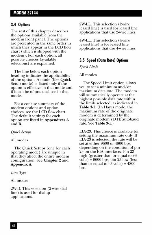
44
MODEM 32144
3.4 OptionsThe rest of this chapter describesthe options available from themodem front panel. The optionsare presented in the same order inwhich they appear in the LCD flowchart (which is shipped with themodem). For each option, allpossible choices (availableselections) are explained.
The line below each optionheading indicates the applicabilityof the option: A mode (like QuickSetup mode) is listed only if theoption is effective in that mode andif it can be of practical use in thatmode.
For a concise summary of themodem options and optionchoices, see the LCD flow chart.The default settings for eachoption are listed in Appendixes Aand B.
Quick Setups
All modes
The Quick Setups (one for eachoperating mode) are unique inthat they affect the entire modemconfiguration. See Chapter 2 andAppendix A.
Line Type
All modes
2W-D. This selection (2-wire dialline) is used for dialupapplications.
2W-LL. This selection (2-wireleased line) is used for leased lineapplications that use 2-wire lines.
4W-LL. This selection (4-wireleased line) is for leased lineapplications that use 4-wire lines.
3.5 Speed (Data Rate) OptionsSpeed Limit
All modes
The Speed Limit option allowsyou to set a minimum and/ormaximum data rate. The modemwill automatically operate at thehighest possible data rate withinthe limits selected, as indicated inTable 3-1. (In Hayes mode, themaximum rate of the originatemodem is determined by theoriginate modem’s DTE autobaudrate. See Table 3-1.)
EIA-23. This choice is available forsetting the maximum rate only. IfEIA-23 is selected, the rate will beset at either 9600 or 4800 bps,depending on the condition of pin23 on the EIA interface: Pin 23high (greater than or equal to +3volts) = 9600 bps; pin 23 low (lessthan or equal to –3 volts) = 4800bps.

45
CHAPTER 3: Options: Customizing the Modem Setup
Table 3-1. Effect of Speed Limit Settings on Data Rate.
Max rate Dialer Resultant data rate, bpssetting, bps option
Leased line modes
14,4001 xx 14,4001
19,200 xx 19,200
12,0001 xx 12,0001
9600 xx 9600
72002 xx 72002
4800 xx 4800
300 to 2400 xx 2400
EIA-CTRL xx 9600 or 48003
Dial modes—Answering
300 to 19,200 xx Negotiated between min.
and max. setting
EIA-CTRL xx 9600 or 48003
Dial modes—Originating
300 to 19,200 OFF or DTR Negotiated between min.
and max. setting
EIA-CTRL OFF or DTR 9600 or 48003
xx HAYES4 Negotiated between autobaud
speed and minimum setting
on originate modem4
xx Does not matter—setting does not affect data rate.1Both 14,000 and 12,000 bps rates are available for the modem.27200 bps is available only if V.32bis mode is enabled (via Summary Setup,
V.32 Mode option).39600 bps if EIA pin 23 is high, 4800 bps if pin 23 is low.4If SYNC AFTER DIAL is enabled (using the &Q1 command), the rate will be
negotiated between the autobaud speed and 1200 bps.
46
MODEM 32144
Speed Matching
If speed conversion is not desired,the DTE interface rate should beset to follow the rate at which themodem connected (i.e., DTE rate =DCE rate, or speed matching).Change the Speed matchingparameter shown in the diagramto 1 (enable).
NOTESpeed matching is onlyeffective for dial applicationsand will only function if errorcorrection or buffer mode isenabled.
Speed Type
All modes
The V.32 master handshakenormally used by the modem isincompatible with the CCITT V.33and Bell 208 handshakes. However,the modem (only) can beconfigured for either V.33 or Bell208 compatibility, and for Bell 208operation. (To determine if amodem supports Bell 208operation, see Section 2.7.)
V.33 or Bell 208 speed types can be set independently of otheroptions via the SPEED TYPEscreen; however, to ensure properoperation, it is recommended that you use the V.33, Bell 208, or V.32/208 Quick Setupconfiguration, as explained inChapter 2.
The available speed-typeselections are listed below. Usepushbuttons 1 (DEC) and 3 (INC)to cycle through the speed-typeselections. The currently selectedspeed type is displayed in theSPEED TYPE screen (upper rightcorner), as shown in Fig. 3-3.

47
CHAPTER 3: Options: Customizing the Modem Setup
Fig. 3-3. Current Speed Type Selection.
Both connected modems must be set for 208A/B operation. For 2-wire applications, the carrieroption must be set for switchedcarrier operation (SWITCH) viathe CARRIER screen, and CTSmust be set to follow RTS (CTSto EIA option).
V.29. This selection is availableonly on models that include theV.29/V.27/V.26 option. Itconfigures the modem for V.29operation (for data rates of 9600,7200, or 4800 bps). To select aspecific data rate, use the SpeedLimit option to select 9600, 7200,or 4800 bps (only) as the minimumand/or maximum data rate (DCERATE). In V.29 mode, the modemdoes not support automatic rateadjustment (fallback) or errorcorrection.
V.32. The modem normally usesthe V.32 handshake. (The modemalso uses this handshake forV.32/14.4 Kbps operation.)
V.33 operation is available on the modem for 4-wire leased-linesynchronous operation only. Theavailable data rates are 14.4 and12.0 Kbps. Either of these rates may be set as the maximum orminimum by using the Speed LimitMAXIMUM RATE and MINIMUMRATE screens.
Both connected modems must beset for V.33 leased line operation.
208. This selection (available onlyon models that support Bell 208operation) provides Bell 208Acompatibility for 2-wire or 4-wireleased line operation and Bell 208Bcompatibility for 2-wire dialoperation. Operation is full duplexin 4-wire leased line mode only. InBell 208B mode, synchronous V.25bis autodialing is available, butHayes operation is not. Calls maybe originated from the front panel.The data rate is fixed at 4800 bpsfor 208A/B operation, and the dataformat is synchronous only.
SPEED TYPE V.32DEC INC
48
MODEM 32144
AUTO. This selection configuresthe modem for V.32/208 auto-detectmode. This mode allows the modemto automatically select V.32 or Bell208 operation, depending on themode of the originating modem.
Note—• To enable V.32/208 auto-detect
mode, the Speed Type optionmust be set to AUTO and theV.32/208 auto-detect SummarySetup option must be set to 1for enable. This option isshown in Appendix B, Fig. B-6.
• Selecting the V.32/208 QuickSetup automatically sets thespeed type to AUTO—andenables the Summary Setupauto-detect option (sets it to 1).
• When the speed type is set toAUTO, the ALX will nothandshake in V.22 bis, Bell212/103 or V.21/V.22,V.23mode.
• All information in the 208section above applies toV.32/208 auto-detect mode.
Three options intended only for208A/B and V.33 operation areaccessible through MODEMSETUPS screen 7. These optionsallow you to select constant orswitched carrier, set CTS to followRTS or set CTS to be always on,or specify an RTS-CTS delay time.For further information, see theCarrier, CTS, and RTS-CTS Delayheadings later in this chapter.
For further information on Bell208 mode, see chapter (sectiontitled Dumb Mode and Bell 208Operation).
3.6 V.42 Error Correction OptionsThe modem supports both CCITT V.42 error correction andMicrocom Networking Protocol(MNP) error correction (classes 1through 5). V.42 and MNP bothprovide end-to-end errorcorrection through an automaticrepeat-transmission requestalgorithm. Both types of errorcorrection enable the modem todetect data-transmission errors and automatically requestretransmission of adversely affecteddata until it is received correctly.
Either error-correction standard(V.42 or MNP) may be enabled foreither dial or leased-line operation.However, error correction canfunction only if all of the followingconditions are present:
• The modem that the modem is communicating with must beequipped with the same type oferror correction (V.42/V.42 bisor MNP).
• The same type of errorcorrection (V.42/V.42 bis orMNP) must be enabled at bothends of the communicationlink.
• Both communicating modemsmust be configured forasynchronous data format.
49
CHAPTER 3: Options: Customizing the Modem Setup
• The connected systems mustsupport data flow control (have buffering capabilities).
Note—• The V.42 and MNP error-
correction options (listed anddescribed below) are effectiveonly when all of the conditionslisted above are present.
• Error-correction options cannotbe changed when the modem ison-line.
• For valid test results, disableerror correction beforerunning diagnostic tests.
User-selectable options let youconfigure the modem for V.42(LAPM) error correction only,MNP error correction only, or V.42error correction with MNP as thefallback (alternate) errorcorrection protocol. Datacompression may also be enabledby selecting either V.42 bis or MNPclass 5 error correction. Othererror-correction options are alsoavailable.
The available error-correctionoptions are V.42 Mode, MNP Class(class limit), Break Handling, V.42Selection, Buffer Mode/SpeedConversion, DTE Speed, DTE-DCEand DCE-DTE Flow Controloptions, and Pass-through FlowControl. All of these options affectthe type of error correctionselected via the V42 SELECTIONscreen (discussed below), exceptthat the MNP Class option is
applicable only to MNP operation.The error correction options can
be selected in any order, but thefollowing sequence is suggested:First select the type of errorcorrection desired from the V.42SELECTION screen. Next make aselection from the V.42 MODEscreen. Then select other errorcorrection options as appropriatefor your application.
Two additional error-correctionoptions are described near the endof this chapter, in Section 3.16,Options Accessible Only viaSummary Setup. These additionaloptions are SelectiveRetransmission and DCE Pass-through Flow Control.
V.42 Mode
Hayes, V.25 bis, Dumb, Leased-linemodes (except V.33)
The V.42 Mode settings describedbelow apply to the type of errorcorrection selected via the V42SELECTION screen. For example,if LAPM ONLY has been selectedas the error correction protocol,and MANDATORY is selected fromthe V42 MODE screen, V.42 or V.42bis error correction will beactivated—or if it cannot be, themodem will hang up.

50
MODEM 32144
OFF. Error correction will bedisabled.
MANDATORY. Error correctionwill be activated. If the modemcannot establish a connection using the type of error correctionselected via the V.42 Selectionoption, it will hang up.
TIGHT FIT = AUTO. The modemwill fall back to buffer or non-buffermode if conditions do not allow itto establish a connection using thetype of error correction selected viathe V42 SELECTION screen.
MNP Class (Limit)
Hayes, V.25bis, Dumb, Leased Linemodes (except V.33)
This option is effective only whenMNP error correction is active. Itlimits MNP operation to theselected MNP class or lower. (MNP classes 1-5 are available.) In general, the higher MNP classesprovide greater throughput. Class5, the default, can provide as muchas 2-to-1 data compression over thetransmission link.
V.42 Selection Options
The following two options areavailable through the V.42SELECTION screen:
Protocol
Hayes, V.25 bis, Dumb, Leased line modes (except V.33)
LAPM/MNP. The modem willattempt to establish a connectionusing the V.42 link access protocolfor modems (LAPM). This is theprimary error correction protocolunder the CCITT V.42 standard.If such a connection cannot beestablished (because the othermodem does not support LAPM oris not configured for LAPM), themodem attempts to establish aconnection using MNP class 5as the fallback (alternate) error-correction protocol.
NOTEWhen operating in LAPMmode, the modem uses V.42error correction unless V.42bis is enabled via the V.42bis option. (V.42 and V.42biserror correction both useLAPM.)
LAPM ONLY. The modem willonly attempt to establish an LAPMconnection (will use only V.42 orV.42 bis error correction).
MNP ONLY. The modem willonly attempt to establish an MNPconnection.

51
CHAPTER 3: Options: Customizing the Modem Setup
NOTEIf a connection cannot beestablished using theselected protocol LAPM/MNP,LAPM ONLY or MNP ONLY),the action the modem willtake depends on the V.42mode setting. See V.42MODE.
V.42 bis Operation
Hayes, V.25 bis, Dumb, Leased linemodes (except V.33)
V.42 bis operation provides errorcorrection with data compression.Like V.42 error correction, V.42 bisuses the link access protocol formodems (LAPM). V.42 bisoperation may be enabled ordisabled.
Break Handling
Hayes, V.25 bis (Async only),Dumb, Leased line modes (exceptV.33)
When error correction is active, a break signal is relayed with an“attention” packet. The breakhandling option determines howthe attention packet is sent.
NONE. No attention packet is sent.
DESTRUCTIVE/EXPEDITED(DESTR/EXP). All data in thebuffer is deleted; the attentionpacket is then passed through thechannel.
NON-DESTRUCTIVE/EXPEDITED (NDT/EXP). Theattention packet is passed throughimmediately, but data in the bufferis not deleted.
NON-DESTRUCTIVE/NON-EXPEDITED (NDT/NEXP). Theattention packet is passed throughthe channel in sequence, and anydata is buffered; this preserves thesequence of data and breaksreceived.
Buffer Mode/Speed Conversion
Hayes, V.25 bis, Dumb, Leased linemodes (except V.33)
This option enables or disablesspeed conversion (forasynchronous operation only)between the DTE and modemwhen error correction is not used.
ENABLE. When error correctionis not active, the V.42 circuit willfunction as a buffer between theDTE and the modem and willprovide transmission-speedconversion.
DISABLE. Speed conversion isnot allowed.
DTE Speed
Hayes, V.25 bis, Dumb, Leased-linemodes (except V.33)

52
MODEM 32144
Flow Control
The flow control options controlthe data flow according to theavailability of memory in thebuffer. Flow control can be setindependently for the terminal to the modem (DTE-DCE) and forthe modem to the terminal (DCE-DTE). The flow control optionsinclude DTE-DCE, DCE-DTE andPass-through Flow Control.
Note the following:
• Flow control only applies toasynchronous connections withV.42 error correction or buffermode enabled.
• When flow control is disabled,the DTE data rate must beequal to or less than themodem data rate, and the localand remote DTE data ratesmust be equal. (This precludesthe need for flow control—which some DTE devicescannot handle—and avoidsbuffer overflow.)
• For DTE-DCE and DCE-DTEFlow Control options: WhenRTS on/off or CTS on/off flowcontrol is used and a bufferconnection has beenestablished, conditions that will stop the data flow (e.g.,dropped RTS) should not bepermitted for long periods, if possible, to reduce thepossibility of buffer overflow.
This option controls the DTEspeed; however, it is effective onlywhen the modem is operating inV.42 mode, MNP mode or buffermode. (If the modem is not in oneof these modes, the DTE speed willbe the same as the connect rate.)
The DTE speed can be set for38.4, 19.2, or 115.2 Kbps or 9600,4800, 2400, 1800, 1200, 600, 300, or 110 bps (except that 1800 bpsis not available if the modem isin Hayes mode). The default DTE speed is 38.4 Kbps.
DTE speed refers to the speed ofdata transfer between the DTE andthe local modem—it is notnecessarily the same as the datatransmission speed between theconnected modems. If flow controlis disabled, the DTE speed must beequal to or less than the modemspeed, and the local and remoteDTE speeds must be equal.
For Hayes mode operation, thisoption sets the default DTE speedthat will be effective after powerupor after a full modem reset.However, the default DTE speed isautomatically overridden when themodem is autobauded (when an“AT” attention code is sent to themodem).
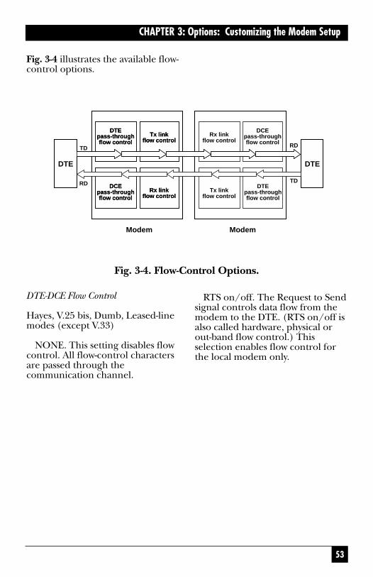
53
CHAPTER 3: Options: Customizing the Modem Setup
Fig. 3-4 illustrates the available flow-control options.
RTS on/off. The Request to Sendsignal controls data flow from themodem to the DTE. (RTS on/off isalso called hardware, physical orout-band flow control.) Thisselection enables flow control forthe local modem only.
DTE DTE
DTEpass-throughflow control
Tx linkflow control
DCEpass-throughflow control
Rx linkflow control
DTEpass-throughflow control
Tx linkflow control
DCEpass-throughflow control
Rx linkflow control
Rx linkflow control
DCEpass-throughflow control
Tx linkflow control
DTEpass-throughflow control
TD
RD
RD
TD
Modem Modem
Fig. 3-4. Flow-Control Options.
DTE-DCE Flow Control
Hayes, V.25 bis, Dumb, Leased-linemodes (except V.33)
NONE. This setting disables flowcontrol. All flow-control charactersare passed through thecommunication channel.

54
MODEM 32144
DTE Pass-through Flow Control
Hayes, V.25 bis, Dumb, Leased-linemodes (except V.33)
Pass-through Flow Control affectsDTE-DCE flow control only. Thisoption determines whether flow-control characters received fromthe local DTE will be passed to theremote modem (if controlcharacters are used for flowcontrol).
ENABLE. Flow control charactersare passed to the remote end of thecommunication connection afterthe modem acts upon them.
DISABLE. Flow controlcharacters are not passed.
3.7 Address
All modes
The address screen allows you toset the address of the modem atyour location. An address may beuseful if the modem will be used in a rack enclosure or in a networkenvironment.
The available address numbersare 000,000 through 999,999. Onthe ADDRESS screen, the threedigits to the right of the comma arethe unit address number. The threedigits to the left are the groupaddress number. To change theaddress, use the right and leftarrow pushbuttons to go to the
DC1/DC2. This option insertsthe control characters ^R and ^Qinto the data stream to stop andstart/restart the flow of data froma device. (DC1/DC2 is also calledsoftware, logical, or in-band flowcontrol.)
DC1/DC3 (X-ON/X-OFF). Thisis the most common method offlow control. It inserts the controlcharacters ^S and ^Q into the datastream to stop (^S) and start/restart (^Q) the flow of data.(DC1/DC3 is also called software,logical, or in-band flow control.)
NOTEWhen using the modem forbinary file transfer, in-bandflow control (flow controlusing control characters)must be disabled. In thiscase, use hardware flowcontrol or, as an alternative,lower the DTE speed toreduce the possibility ofoverflow.
DCE-DTE Flow Control
Hayes, V.25 bis, Dumb, Leased-linemodes (except V.33)
All information given aboveunder DTE-DCE Flow Control alsoapplies to the DCE-DTE (modemto terminal) flow control option,except that the CTS, Clear to Sendsignal, is used to control DTE-DCEdata flow.

55
CHAPTER 3: Options: Customizing the Modem Setup
NOTEDTR dialing for V.25 bismode or Penril autodialermode cannot be enabledthrough the DIALER screen.To select DTR dialing forV.25bis or Penril mode, youmust use the Penril/V.25bisDTR Dialing option.
V.25 bis Dialer Modes
V.25 bis mode
Any of the selections from theDIAL V25 bis screen will enable the V.25 bis autodialer.
The three selections on the DIALV25bis screen allow you to select adata protocol that is appropriatefor the DTE the modem isconnected to. The choices are—ASYNCHRONOUS (Asyn)SYNCHRONOUS, CHARACTERORIENTED (Syn_c), andSYNCHRONOUS, BIT ORIENTED(Syn_b)
3.9 Auto-Answer OptionAuto-Answer
Hayes, V.25 bis, Dumb, 208,V.32/208 modes
This option determines whetheror not a call is automaticallyanswered when the phone rings.
digit you want to change. Then usepushbutton 1 to decrease (DEC) a number and pushbutton 3 toincrease (INC) it. The defaultaddress is 999,999.
3.8 Dialer ModeSeveral dialer mode options can be selected from the DIALER and DIAL V25bis screens.
Dialer
All modes
See also V.25 bis Dialer Modesbelow.
OFF. The autodialer is off,meaning the modem will operatein Dumb mode only. Calls must bemade using the front panel AUTO-DIAL function or they must bemanually originated.
HAYES. The autodialer willautomatically dial previously storedphone numbers, and the modemwill respond to Hayes commands.
DTR. This selection enables DTRdialing, an option that allows youto set up the modem toautomatically dial a stored numbereven when the autodialer has notbeen enabled.

56
MODEM 32144
Setting the Auto-Answer optionto ENABLE resets Hayes moderegister S0 to 1 (meaning that callswill be answered on the first ring).
3.10 Data Format OptionsData Format (Sync or Async)
V.25 bis, Dumb, Leased line modesThe data-format setting for thelocal modem and for the remotemodem must be the same.
ASYNCHRONOUS. Data istransmitted and received in thecharacter asynchronous format.The character length (next option)must be the same for bothcommunicating modems.
SYNCHRONOUS. If this settingis selected, data must betransmitted and received in thesynchronous format. Theappropriate transmitter clockingsetting must be selected—seeTRANSMITTER CLOCKING laterin this chapter. The synchronousdata format is not available for datarates of 300, 19.2, or 38.4 Kbps.
Character Length
All modes (asynchronousoperation only)
This option selects a characterlength of 9, 10, or 11 bits forcharacter asynchronous operation.The same character length must be
selected for both the local and theremote modems. Use pushbuttons1 and 3 to select the desiredcharacter length. The most widelyused character-length setting is 10 bits.
9 BITS: 1 start bit, 7 data bits,and 1 or more stop bits.
10 BITS: 1 start bit, 8 data bits,including parity, and 1 or morestop bits.
11 BITS: 1 start bit, 9 data bits,including parity, and 1 or morestop bits.
Parity
All modes
Parity selections will be effectiveonly if error correction or buffermode has been enabled or if themodem is in 2-wire dial Hayesmode. For most applications, parityshould be set to NONE.
The following parity options areavailable: NONE (no parity),ODD, EVEN, MARK (parity isalways 1) and SPACE (parity isalways 0). All parity settings exceptNONE automatically enable parityconversion (except in Hayesmode), meaning that the parity ofreceived data will be converted tomatch the selected parity option.

57
CHAPTER 3: Options: Customizing the Modem Setup
NOTEFor Hayes mode operation,the RX Space Disconnectand TX Space Disconnectoptions must both beenabled or must both bedisabled.
TX (Transmit) Space Disconnect
Hayes, V.25 bis, Dumb modes
When TX Space Disconnect isenabled, the modem will transmit 4 seconds of space prior todisconnecting from the line. Thisensures a clean disconnect if RXspace disconnect is enabled on theremote modem.
NOTEFor Hayes mode operation,the TX Space Disconnectand RX Space Disconnectoptions must both beenabled or must both bedisabled.
Carrier Disconnect
V.25 bis, Dumb modes
If enabled, a 400-ms loss ofcarrier signal will cause the line to be disconnected.
(To set this option for Hayesmode, use S register S10.)
In Hayes mode, autobaudoverrides the front panel paritysetting; this occurs when themodem receives the AT attentioncode.
3.11 Disconnect OptionsWhen the modem is operating inV.25 bis or Dumb mode, it isnecessary to disconnect the modemfrom the telephone circuit oncecommunications is completed. Themost common form ofdisconnection is by dropping theData Terminal Ready (DTR) signalfrom the DTE. However, someapplications may require one of thefive available automatic disconnectmethods listed below.
For all five disconnect options,“disabled” means the modem willnot disconnect in the presence ofthe conditions specified below
RX (Receive) Space Disconnect
Hayes, V.25 bis, Dumb modes
If this option is enabled, a 1.6-second continuous space will causethe modem to disconnect.

58
MODEM 32144
Line Current Disconnect
V.25 bis, Dumb modes
If enabled, a 400-ms loss ofcurrent will cause the line to bedisconnected.
(To set this option for Hayesmode, use S register S10.)
RTS Disconnect
Hayes, V.25 bis, Dumb modes
When RTS Disconnect isenabled, if RTS is off for a selectedperiod of time (20 to 140 seconds,user-selectable), the line will bedisconnected. Use pushbuttons 1and 3 to set the RTS-OFF periodrequired for a disconnect.
3.12 Test OptionsThe test options affect certain tests(as explained below) but do notactivate tests.
DSR During Analog Loopback
All modes
When ON is selected, the DataSet Ready signal is forced on whenthe modem is in the analogloopback test mode. In general,this option should be left ON (thedefault selection).
Remote Test
All modes
The Remote Test option allowsyou to prevent remote digitalloopback or remote digitalloopback self tests from beinginitiated on the local modem froma remote modem. If DISABLE isselected from the REMOTE TESTscreen, the local will ignore test-initiation signals from a remotemodem. If ENABLE is selected,tests can be initiated from a remotemodem.
Note that there are two REMOTETEST screens. One is for theoption just described; the other isused for selecting remote digitalloopback tests. The Remote Testoption screen (for preventing orallowing remote testing) looks likethis:
REMOTE TEST ENABLE DISABLE
3.13 EIA OptionsThe seven options described nextallow control over specific EIAinterface signals.
59
CHAPTER 3: Options: Customizing the Modem Setup
CTS to EIA
Hayes, V.25 bis, Dumb, Leased-linemodes (except V.33)
Regardless of the setting selectedfor this option, Clear to Send(CTS) goes low. When DCD goeshigh during a V.42 error correctionhandshake or when DCE-DTE flowcontrol is set to CTS on/off and aconnection has been establishedwith error correction or buffermode enabled.
NORMAL. The Clear to Sendsignal is on while the modem is on-line.
RTS. The CTS signal immediatelyfollows the RTS signal with nodelay.
TRUE. The CTS signal followsDTR.
CTS can also be set to be ON atall times regardless of DTR by usingthe Summary Setup feature.(However, if CTS on/off has beenselected from DCE-DTE screen 1,V.42 flow control, while active, willoverride the CTS ON selection.)
To set CTS ON, refer toAppendix B, Fig. B-4 , EIAINTERFACE OPTIONS diagram.Note that if you set CTS to ONusing Summary Setup and thenmake a selection from the CTS toEIA screen, the selection from theCTS to EIA screen will cancel theSummary Setup (CTS ON)selection.
NOTEThe modem also supports aCTS option intended onlyfor V.33 and Bell 208A/Boperation, which isdescribed later in thischapter under V.33 and Bell208A/B Options.
CD to EIA
All modes
NORMAL. Carrier Detect (CD) is on while the modem is on-line.
TRUE. CD follows DTR suppliedfrom the DTE.
TOGGLE. CD turns on wheneverDTR is present and then toggles offfor 500 ms upon DTR disconnect,allowing the attached DTE torecognize that the call has endedand the connection has beendropped.
DSR to EIA
All modes
NORMAL. Data Set Ready (DSR)is on while the modem is on-line.
TRUE. DSR follows DTRsupplied from the DTE.
CROSSOVER (XOVER). DSR isON without DTR and toggles for500 ms upon local or remotedisconnect.

60
MODEM 32144
DTR from EIA
All modes
This option allows the user toforce the Data Terminal Ready(DTR) signal on (TRUE), whichmay be needed if your computer orcommunication software does notsupply a DTR signal.
NORMAL. DTR is supplied bythe DTE. When DTR goes low, themodem sends a space disconnect(if TX Space Disconnect isenabled) and goes on-hook.
TRUE. The DTR signal isinternally forced ON regardless of the DTR status at the interface.
DTE Control of ALB (ALB- DTECtrl’ed)
All modes
Analog loopback (ALB) testingcan be initiated from the DTE viapin 18. Positive voltage activates the test, whereas negative voltageresults in normal operation.Disabling this option keeps themodem from responding to pin 18.
DTE Control of RDL (RDL- DTECtrl’ed)
All modes
Remote digital loopback (RDL)testing can be initiated from theDTE via pin 21. Positive voltageactivates the test, whereas negative
voltage results in normal operation.Disabling this option keeps themodem from responding to pin 21.
Test Mode (TM to EIA)
All modes
This option controls pin 25, thetest mode (TM) indicator, on theRS-232 interface connector.NORMAL. TM output is high(active) only during test modes.TRUE. TM output is high all ofthe time.
3.14 Modem SetupsThe options listed below, throughRTS-CTS Delay, are available viathe MODEM SETUPS screens.
Carrier Detect
All modes
This option selects the carrierdetect level. To make a selection,first select either LEASED or DIALfrom the CARRIER DET. LVLscreen, depending on yourapplication. The appropriatecarrier detect level screen will then be displayed.
Leased-Line Applications
For leased-line use, the carrierdetect level can be set for –43, –33or –26 dBm. The default setting is–26 dBm.

61
CHAPTER 3: Options: Customizing the Modem Setup
Dialup Applications
For dial line use, the carrier detectlevel can be set for –51, –41 or –34dBm. The default setting is –51dBm.
Transmit Level
All modes
This option controls the modem’stransmission level. To make aselection, first select eitherLEASED or DIAL from theTRANSMIT LEVEL screen.
Leased Line Applications
For leased lines, the transmissionlevel can be set between 0 and –15dBm, in 1-dBm steps. The standardsetting is 0 dBm. (Use pushbuttons1 and 3 to select the desiredtransmission level.)
Dialup Applications
The transmission level for dial linescan be set as either programmable,if you are using RJ-45S connectors,or permissive, fixed at –10 dBm+/–1 dBm, which is the mostcommon setting.
Signal Quality
All modes
This option sets the threshold forthe ER (error) indication duringnormal operation. You can chooseeither 10^3, one error in 1000 bits,or 10^5, one error in 100,000 bits.The settings of the Signal Qualityand Carrier Detect Level optionsdetermine the threshold values themodem uses as criteria for enteringLeased Line Auto-Recovery mode.
Compromise Equalizers
Hayes, V.25 bis, Dumb, Leased-linemodes (except V.33)
NOTEThe compromise equalizersonly affect V.32 operation(4800 bps to 14.4 Kbps,asynchronous/synchronous,full duplex).
For most applications, theautomatic adaptive equalizersetting will provide all the equaliza-tion necessary to compensate forline impairments, meaning thatequalizer adjustments generally willnot be necessary. However, in theevent that equalizer adjustment isneeded, any of four types ofcompromise equalization can beselected: Type I (T-I on the LCD),Type II (T-II), Type III (T-III) andType IV (T-IV). The equalizer canalso be turned OFF.

62
MODEM 32144
Where line conditions areatypical, it may be necessary toadjust the equalizers to optimizethe signal quality. If adjustment isnecessary, refer to the qualityscreen for guidance; this screenshows a relative indication of thesignal quality, in both numericand graphic form.
Trellis Code
Hayes, V.25 bis, Dumb, Leased linemodes (except V.33)
Trellis coding providesperformance advantages for allmodulation patterns. The modem’sCCITT compliant trellis coder isnormally enabled at speeds of 7200 bps and above, but may benegotiated off by a modem that isnot equipped with a trellis coder at9600 bps. The trellis code optionallows the user to enable or disablethe trellis coder.
Transmitter Clocking
All modes
This option selects one of threepossible sources for the transmittertiming signal:
INTERNAL. The timing of themodem and data terminaltransmitting circuits is provided by an internal clock within themodem.
RECEIVED (RX-CLK). Thetiming of the data received fromthe remote modem is used tocontrol the timing of the trans-mitted data. This timing mode isused if the modem’s transmittiming must be controlled by aremote source.
EXTERNAL. The timing of the modem and data-terminaltransmitting circuits is synchro-nized to an external clock fromwithin the data terminal and isprovided to the modem via theDTE connector pin 24. This mode of clocking is used if theDTE must be in control of themodem’s transmit timing. Themodem’s minimum and maximumspeed must be set to approximatelythe same speed as the DTE clock.(To set the maximum speed, usethe Speed Limit option.)
T1 Timer
Hayes, V.25 bis, Dumb modes
The T1 Timer option is onlyeffective if the Summary SetupMultimode Handshake option is set to 0 (T1 timer).
The T1 Timer option determineshow long the ALX modem willattempt to handshake with a callingV.32 modem before falling back toa lower speed. The available T1Timer settings are 0, 0.3, 0.8, 1.6and 3.0 seconds.

63
CHAPTER 3: Options: Customizing the Modem Setup
Normally, as part of the V.32handshake, the calling modembegins sending a sequence to theanswer modem while the answermodem is still sending answertone—in this case, there is no T1timer. However, the V.32Recommendation allows for a T1time of up to 3 seconds, meaningthat the answer modem may be setto wait (before falling back) for upto 3 seconds.
Auto-Retrain
Hayes, V.25 bis, Dumb, Leased-linemodes (except V.33)
If the modem makes aconnection at one of the V.32 rates(4800 bps to 14.4 Kbps) or V.22 bisrate (2400 bps), it can request thatthe remote modem send a retrainsequence.
ENABLE. The modem willrequest a retrain sequence.
DISABLE. The modem will notrequest a retrain sequence.
Answer/Originate Default
Leased line modes (and manualoriginate/answer dial operation)
This option sets the modem todefault to either answer ororiginate status when it makes aconnection at one of the V.32 rates(4800 to 14.4 Kbps). It also appliesto the V.22 bis rate (2400 bps), fordial operation only.
ANSWER. The modem is set toanswer mode.
ORIGINATE. The modem is setto originate mode.
Answer Tone
Hayes, V.25 bis, Dumb modes
The answer tone frequency isselectable only if the maximumdata rate has been set to 1200 bps(via the SPEED LIMIT menu), inwhich case the answer tone can beset to either 2225 or 2100 Hz.Otherwise, the answer tonefrequency will be 2100 Hz (thestandard for V.32 operation). Ingeneral, this setting should not be changed (even for fallback withBell standard modems, which use a2225 Hz answer tone).
Front-Panel Control
All modes
For security purposes, this optionmay be used to make it difficult forunauthorized users to modify themodem’s configuration. If Front-Panel Control is disabled, themodem will not respond to QuickSetup selections or to changesmade through option screensaccessed via the SETUP menus. In addition, Hayes configurationcommands (and the &W and &ZHayes commands) will have noeffect, and stored user profiles (forHayes mode) cannot be altered.Note that even if Front-Panel

64
MODEM 32144
Control is disabled, front-panelscreens that do not affect themodem configuration (such asAUTO-DIAL and test modes) will function.
Speaker
Two speaker options are available:Speaker Control and SpeakerVolume.
Speaker Control
All modes
ON. Speaker is on during the fullmodem handshake process andwhile the unit remains on-line.
OFF. The speaker is off; the callcannot be audibly monitored.
ON TILL CD. Speaker remains on until a carrier signal (CD) isdetected.
Speaker Volume
All modes
The speaker volume can be set to LOW, MEDIUM, or HIGH.
Guard Tones
Hayes, V.25 bis, Dumb modesGuard tones are used—in V.22 and V.22 bis modes only—to assureproper band separation on systemsthat use international telephonecircuits. Unless you will be usinginternational circuits in one of
these modes, you should turn theguard-tone option OFF. If guardtones are required, their frequencycan be set to 550 Hz or 1800 Hz(the most commonly used guard-tone frequency).
V.13 Operation
V.25 bis, Dumb, Leased-line modes(synchronous operation only)
OFF. V.13 operation is off. Thissetting allows normal full-duplexoperation. (All other selections arefor enabling V.13 operation.)
TX ONLY. Status of RTS will besent to remote modem.
RX ONLY. Carrier Detect (CD)will be controlled by V.13 signalsfrom the remote modem.
TX AND RX. Status of RTS willbe sent to remote modem, and CDwill be controlled by V.13 signalsfrom the remote modem.To select one of the four V.13options, press pushbutton 1 or 3—with the V13 screen displayed—until the selection you want isdisplayed. For half-duplex point-to-point applications, select TX ANDRX. For multidrop-typeapplications, select RX ONLY forall modems at the host site and TXONLY for all modems at theremote site.
65
CHAPTER 3: Options: Customizing the Modem Setup
NOTEIf V.13 operation is enabled(TX ONLY, RX ONLY or TXAND RX), the data format isautomatically changed tosynchronous. However, ifyou enable V.13 operationand later disable it, the dataformat does notautomatically revert toasynchronous. To restorethe asynchronous dataformat, you must use theData Format option.
3.15 V.33 and Bell 208A/B OptionsThe following three options areavailable on the modem and areintended only for V.33 or Bell208A/B operation. (For Bell 208operation, see also Satellite Delay,Turnaround Delay, 208 PhaseDetection, Answer Tone Detectionand V.32/208 Auto-Detect Modelater in this chapter.)
Carrier Type
V.33, 208, V.32/208 modes
SWITCHED (SWITCH). For 2-wire applications, the carrier typeoption must be set for switchedcarrier operation.
CONSTANT. Constant, orcontinuous carrier can be usedonly for 4-wire leased lineapplications (although suchapplications may also use switchedcarrier).
CTS
V.33 mode
This option applies only to V.33leased-line applications that useconstant carrier.
RTS. The CTS signal follows RTS.
ON. CTS is always ON.
NOTEThe modem also supports aCTS to EIA option, which isdescribed in Section 3.11.
RTS-CTS Delay (CTS Delay)
V.33, 208, V.32/208 modes
The available RTS-to-CTS delaysettings are 0, 15, 50, or 150 ms.However, the only available choicesfor 208A/B operation are 50 and150 ms. If you select 0 or 15 ms, theactual delay in 208A/B mode willbe 50 ms.

66
MODEM 32144
NOTERTS-to-CTS delay is noteffective if the CTS option isset to ON (always ON). ForV.33 operation, RTS-to-CTSdelay is only effective for 4-wire leased line applicationsthat use constant carrier.
RTS-CTS Delay with V.13 Operation
If the V.13 Operation option is setto TX ONLY or TX AND RX, theactual RTS/CTS delay time maydiffer from the selected RTS/CTSDelay setting. The actual RTS/CTSdelay depends on the data rate, asshown in Table 3-2.
Table 3-2. RTS/CTS Delay with V.13 Operation.
Data Rate Delay Setting, msbps
0 15 50 150
Actual Delay, ms
14,400 9 15 50 106
12,000 9 15 50 106
9600 8 15 50 106
7200 6 15 50 106
4800 10 15 50 106
2400 16 16 50 150
1200 29 29 50 150
600 65 65 65 150

67
CHAPTER 3: Options: Customizing the Modem Setup
3.16.1 DIAL LINE OPTIONS
(The numbers used to selectdifferent settings for each optionon the Summary Setup LCD screenare arranged according to optiongroups—dial line options, V.42error-correction options, etc. Fordetails, see Appendix B.)
Wait for Carrier
V.25 bis, Dumb modes
The time the modem will wait for acarrier signal when originating acall can be set for 30, 45, 60, or 75seconds. (Note: In Hayes mode,the wait-for-carrier time isdetermined by the value in register S7.)
3.16.2 V.42 ERROR-CORRECTIONOPTIONS
Selective Retransmission
Hayes, V.25 bis, Dumb, Leased-linemodes (except V.33)
This option allows the modem tocommunicate with certain modemsthat are not able to respond to theMNP selective retransmissioncommand.
ENABLE. This setting allows themodem to request retransmissionof a single information frame (inthe event of a transmission error).
DISABLE. Data can beretransmitted only in a series of information frames.
LCD Intensity
All modes
This option allows you to usepushbutton 3 (for INC or increase)to darken characters on the LCDor pushbutton 1 (for DEC ordecrease) to lighten them.
3.16 Options Accessible Only viaSummary SetupThe options described in thissection can only be changedthrough the modem’s SummarySetup feature, which is explainedin Appendix B. For mostapplications, it is not necessary tochange these options—they areintended primarily for specializedapplications. For an explanation ofhow to change these options,available option settings and thedefault setting for each option, seeAppendix B.
Three additional optionsaccessible only via Summary Setupinclude Operating Mode Fallback,Rate Renegotiation Procedure, andSpeed Fallback.

68
MODEM 32144
DCE Pass-through Flow Control
Hayes, V.25 bis, Dumb, Leased-linemodes (except V.33)
This option affects DCE-DTEflow control only. It is effective onlyif error correction or buffer-mode/speed conversion is enabled.
ENABLE. The modem will passflow-control characters receivedfrom the remote modem to thelocal DTE.
DISABLE. The modem will notpass flow control characters fromthe remote modem to the localDTE.
Link Flow Control
Hayes, V.25 bis, Dumb, Leased linemodes (except V.33)
This option is effective only ifbuffer-mode/speed conversion isenabled and a buffer link withouterror correction is established. Donot enable Link Flow Control ifbinary data will be transmitted orreceived.
ENABLE. The modem will checkfor X-ON/X-OFF (DC1/DC3) flow-control characters received fromthe remote modem to determinewhether to stop or start/restartdata transmission to the remotemodem. A DC3 control characterwill cause the modem to stop datatransmission and hold data in itsbuffer until it receives a DC1
control character (which instructsthe modem to resumetransmission).
If Link Flow Control is enabledwith DTE-DCE flow control set toRTS on/off and DCE-DTE flowcontrol set to CTS on/off on boththe originating and answeringmodems, and both modemsestablish a buffer-modeconnection, the modems willexchange flow control signalsacross the link in the form of DC1and DC3 characters. If the databeing exchanged contains a DC3character (e.g., binary orexecutable files), this will signal theremote modem to halt and bufferall data from the remote DTE untilthe local DTE sends a DC1character.
DISABLE. The modem willignore XON/XOFF (DC1/DC3)flow -control characters receivedfrom the remote modem.
SLAVED. Link flow control iscontrolled by the DCE-DTE FlowControl option. If DCE-DTE FlowControl is set to NONE or CTS,Link Flow Control is disabled.Otherwise it is enabled.

69
CHAPTER 3: Options: Customizing the Modem Setup
3.16.3 DATA PUMP OPTIONS
Phase Reversal in Answer Tone
All modes
When enabled, the Phase Reversalin Answer Tone option signals thetelephone network to turn off itsecho cancelers. For virtually allapplications, phase reversal shouldbe enabled (the default setting).
Satellite Delay
208, V.32/208 modes
This option facilitatestransmission over satellite links(but does not permit fast-turn-around operation). When theSatellite Delay option is on, RTSis inhibited for 275 ms after theanswer tone stops and after theDSR signal comes on. This delayoccurs at both the originating andanswering modems, allowing theecho suppressors on the telephonelink to be enabled.
Turnaround Delay
208, V.32/208 modes
This option is intended for circuitswhere echo is a problem. It pre-vents the modem from receiving an echo of its own transmitted data.When the Turnaround Delayoption is on, CD (pin 8) is held lowfor 150 ms after RTS is turned off.If the modem detects an energyloss during the delay, it turns CDon 52 ms after detecting the loss. If
the modem does not detect anenergy loss, it turns CD on 52 msafter the end of the delay. Themodem ignores any energy lossduring the first 8.5 ms.
V.32 Mode
Hayes, V.25 bis, Dumb, Leased-linemodes (except V.33)
This option is used to selectCCITT V.32 bis operation or V.32extended operation.
V.32bis. When V.32bis mode isselected (factory-default setting),the following are available: RateRenegotiation Procedure (RRP), a data rate of 7200 bps, and a RATE screen that allows the user to manually initiate RRP.
RRP enables the modem toautomatically fall back or fallforward to a lower or higher datarate during data transmission inresponse to changes in signalquality. Selecting V.32 bis modemakes RRP available as an option;however, RRP will not functionunless it is enabled. (Enabled is thefactory-default setting.) RRP isdescribed fully in Section 4.3.2.
When V.32 bis mode is selected,a RATE screen is available fromMAIN MENU screen 3. The RATEscreen can be used to manuallyinitiate RRP for diagnosticpurposes. For additionalinformation, see RATE CHANGESCREEN in Section 8.7.

70
MODEM 32144
When V.32bis mode is selected,7200 bps can be selected as themaximum or minimum data rate(using the Speed Limit option).When V.32bis is not selected, 7200-bps operation is not available.
NOTEBy definition, V.32 bisoperation includes theability to operate at 12,000and 14,400 bps. However,RRP, the 7200-bps data rate,and the RATE screen areavailable on the modemwhen V.32 bis is selected.
V.32 EXTENDED. V.32 extendedmode disables the V.32 bis features.In V.32 extended mode, themodem’s functionality is identicalto that of modems prior toincorporation of the CCITT V.32bis recommendation.
208 Phase Detection
208, v.32/208 modes
NORMAL. Conditions themodem’s 208 receiver forcompensated modulation detectionfor improved performance witholder 208 modems.
V.22 bis S1 Duration
Hayes, V.25 bis, Dumb modes
This option affects the durationof the S1 signal during a V.22 bishandshake. To allow the modem toconnect properly with certain
manufacturers’ V.22 bis modemsthat do not conform fully with theV.22 bis standard, the modem’s S1signal duration may have to bechanged from the default setting,100 ms, to 150 ms. The CCITT V.22bis specification specifies an S1duration of 100 ms.
V.32/208 Auto-Detect Mode
208, V.32/208 modes
To enable V.32/208 auto-detectmode, the V.32/208 auto-detectSummary Setup option must be setto 1 for enable and the front panelSpeed Type option must be set toAUTO. (If you select the V.32/208auto-detect Quick Setup, themodem automatically sets both ofthese options to enable V.32/208auto-detect mode.)
When V.32/208 auto-detectmode is enabled, the modemautomatically selects V.32 or Bell208 mode, depending on the mode of the originating modem.
3.16.4 MISCELLANEOUS OPTIONS
V.25bis DTR Dialing
V.25 bis mode
This option enables or disablesDTR dialing for V.25 bis mode only.If this option is enabled, DTRdialing will function in V.25 bismode—depending on which ofthese modes (i.e., whichautodialer) is enabled.
71
CHAPTER 3: Options: Customizing the Modem Setup
ENABLE. Enables DTR dialing forV.25 bis mode.
DISABLE. Disables DTR dialing forV.25 bis mode.
Analog Loopback Make Busy
All modes
If the Analog Loopback Make Busyoption is enabled, the modem willprovide a busy indication to thedial-line interface when themodem is in analog loopback testmode.
Answer Tone Detection
208, V.32/208 modes
ENABLE. Conditions theoriginating modem’s receiver to wait for answer tone detectionbefore going on-line.
DISABLE. Conditions theoriginating modem to go on-linewithout requiring answer tonedetection. This setting accom-modates operation with automaticcalling units that connect themodem to the line at the end ofanswer tone.
Multimode Handshake
Hayes, V.25 bis, Dumb modes
This option determines how longthe modem will attempt to hand-shake with a V.32 modem beforefalling back to a lower speed.
T1 TIMER. If the T1 timersetting is selected, the modem willattempt to handshake with a callingV.32 modem for the time specifiedby the T1 Timer option.
V.32 bis ANNEX A. If the V.32 bisAnnex A setting is selected, themodem will handshake accordingto the conventions established inAnnex A of the CCITT V.32 bisrecommendation. Handshakingusing the Annex A selection willgenerally be faster thanhandshaking based on the T1timer.
Remote RTS Signaling
Leased line modes (except V.33)
This option provides remote RTSsignaling in asynchronous mode.When the Remote RTS Signalingoption is on, the state of the Readyto Send (RTS) signal is transferredacross the modem link (fordiagnostic purposes) withoutaffecting normal operation. TheRemote RTS Signaling optionallows control over the remoteCarrier Detect (CD) signal asdescribed below.
Note the following restrictionsfor Remote RTS Signaling: The twomodems must be connected at adata rate of 7200 bps or higher.The V.13 Operation option must be off. The DTE-DCE and DCE-DTE Flow Control options shouldnot be set to RTS on/off.
72
MODEM 32144
Wait for MNP Link Request
Hayes, V.25 bis (Async only),Dumb, Leased-line modes (except V.33)
When a remote originatingmodem attempts to establish anMNP connection with a modem,the answer modem will wait up to3 seconds, by default, to receivethe MNP link request. This optionallows the user to configure themodem to wait longer (7 seconds)for an MNP link request. Thelonger wait time allows the modemto establish MNP connectionsunder conditions that requiremultiple link requests.
CFI AB Response on Disconnect
V.25 bis
In V.25bis mode, the originatemodem sends a CFI AB result codewhen a call is aborted because theuser has selected HANGUP fromthe front panel or because of DTRloss. If the CFI AB Response onDisconnect option is enabled, theoriginate modem will also send aCFI AB result code upon calldisconnect.
ON. The state of RTS input (EIA pin 4) will be signaled to theremote modem’s CD output, andCD (pin 8) on the local modemwill follow the state of the remotemodem’s RTS input. (The typicalpropagation delay is less than 800ms.)
OFF. This setting allows fornormal operation: The state ofRTS at the local modem will not be signaled to the remote modem.
Leased Line Interrupt
Leased-line modes (except V.33)
The Leased Line Interruptoption controls a modemdesignated as the answer modemand configured for Leased LineAuto-Recovery (Section 4.9) asstated below.
ON. The answer modem willanswer incoming calls, regardless of the state of the leased line (CDON or OFF).
OFF. This setting allows fornormal operation: If CarrierDetect (CD) is ON, this means theleased line is trained and working,and the answer modem will ignoreany incoming calls on the dial line.

73
CHAPTER 3: Options: Customizing the Modem Setup
Low-Profile DIAG LED Function
All modes
This option may be used tochange the function of the DIAGLED on low-profile modems(Appendix D), as explained below.
CONNECT STATUS. DIAG LEDon indicates the modem’sdiagnostic port is activelyconnected. DIAG LED off indicatesthe diagnostic port is notconnected.
DTR STATUS. DIAG LED onindicates DTR is high. DIAG LEDoff indicates DTR is low.

14
MODEM 32144
2.1.2 CONNECTIONS
Fig. 2-1 shows how the modem isconnected to the computer orterminal, power, phone lines, andhandset (optional). Do not installthe modem more than 50 feet (15.2 m) from the DTE. This is the EIA recommended maximumlength for interface cable.For all applications—
• Connect the modem connectormarked “DTE” to the computeror other DTE. Use an EIA RS-232 interface cable (notsupplied with the modem)to make this connection.
• Attach the power transformercable (supplied with themodem) to the modemreceptacle marked “POWER,”and plug the other end into a115-VAC power outlet.
For dialup applications—• Connect the modem to the
telephone line modular walljack, as follows: Use the cable(supplied) that has an eight-pinmodular connector on one endand a six-pin modularconnector on the other. Plugthe eight-pin connector end ofthe cable into the modem jacklabeled “TX DIAL.” Then plugthe six-pin connector end intothe telephone line modularwall jack. Do not bundle thetelephone and EIA interfacecables together.
• Optional: If you want to usethe telephone line for voicetransmissions (when themodem is not operating in data mode) or for manual dial operation, plug a standardtelephone set into the jack inthe rear of the modem labeled“PHONE.”
For leased line applications—• Attach the six-pin modular-
connector end of the four-conductor cable (supplied) tothe modem connector labeled“LEASED LINE.” Attach thespade-lug end of the cable intothe line terminal block.
The same cable is used whetherthe leased line is a 4-wire or 2-wire line. In a 4-wireapplication, the green and redwires are the TRANSMIT pairof wires, and the yellow andblack wires are the RECEIVEpair. When the cable isconnected to a 2-wire line, onlyits green and red wires are used(and the yellow and black wiresshould be cut off).
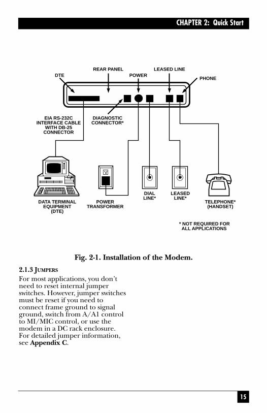
15
CHAPTER 2: Quick Start
Fig. 2-1. Installation of the Modem.
DTEREAR PANEL LEASED LINE
POWERPHONE
DIAGNOSTICCONNECTOR*
EIA RS-232CINTERFACE CABLE
WITH DB-25CONNECTOR
DATA TERMINALEQUIPMENT
(DTE)
POWERTRANSFORMER
DIALLINE*
LEASEDLINE*
TELEPHONE*(HANDSET)
* NOT REQUIRED FOR ALL APPLICATIONS
2.1.3 JUMPERS
For most applications, you don’tneed to reset internal jumperswitches. However, jumper switchesmust be reset if you need toconnect frame ground to signalground, switch from A/A1 controlto MI/MIC control, or use themodem in a DC rack enclosure.For detailed jumper information,see Appendix C.
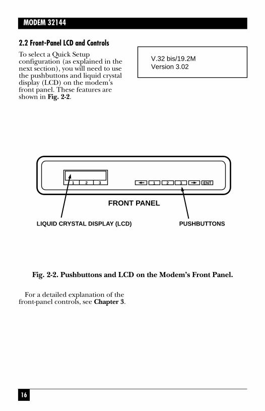
16
MODEM 32144
2.2 Front-Panel LCD and ControlsTo select a Quick Setupconfiguration (as explained in thenext section), you will need to usethe pushbuttons and liquid crystaldisplay (LCD) on the modem’sfront panel. These features areshown in Fig. 2-2.
LIQUID CRYSTAL DISPLAY (LCD)
1
PUSHBUTTONS
FRONT PANEL
2 3 ENT1 2 3
Fig. 2-2. Pushbuttons and LCD on the Modem’s Front Panel.
For a detailed explanation of thefront-panel controls, see Chapter 3.
V.32 bis/19.2MVersion 3.02

17
CHAPTER 2: Quick Start
2.2.1 POWER-ON SCREEN
When the modem is powered on,the unit momentarily displays thepower-on screen, which typicallylooks like this:
D=Dial line occupied
R=Ringing (R appears in sameposition as D.)
S=Connection secured by securityhandshake (S appears in the sameposition as D. S and D may flashalternately.)
TR=Data Terminal Ready
MR=Data Set Ready
RS=Request to Send
CS=Clear to Send
TD=Transmit Data
14,400, 9600, 4800, etc.=Data speedin bits per second (“idle” or H-01,H-14, etc. may also be displayed inthe data speed position; see below.)
TM=Test mode
ER=Error (poor signal quality)
CD=Carrier Detect
RD=Receive Data
Codes beginning with “H” (suchas H-01) in the lower left corner ofthe status screen indicate that themodem is handshaking withanother modem (attempting toestablish a connection). When themodem is off-line, the word “idle”is displayed in the same position.
V.32 bis/19.2MVersion 3.02
The numbers displayed in thelower right corner are the revisionlevels of the software used in themodem. The software revisionlevels displayed by your unit may be different than those shownabove. If you need to call TechnicalSupport, please be prepared to givethe support group the softwarerevision levels of your unit.
The modem spends about twoseconds checking the ROMchecksum and doing self-tests andthen displays the EIA status screen.
2.2.2 EIA STATUS SCREEN
The EIA status screen indicates theoperational status of the modem aswell as the condition of certain EIARS-232 leads. The abbreviationsthat may appear are identifiedbelow; however, typically only a few of these abbreviations will bedisplayed during actual operation.
D TR MR RS CD TD9600 TM ER CD RD
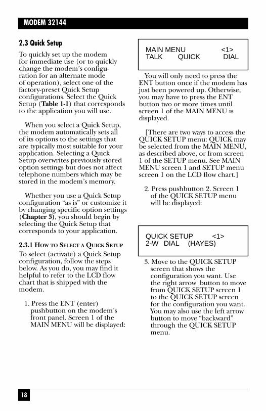
18
MODEM 32144
2.3 Quick SetupTo quickly set up the modem for immediate use (or to quicklychange the modem’s configu-ration for an alternate mode of operation), select one of thefactory-preset Quick Setupconfigurations. Select the QuickSetup (Table 1-1) that correspondsto the application you will use.
When you select a Quick Setup,the modem automatically sets all of its options to the settings that are typically most suitable for yourapplication. Selecting a QuickSetup overwrites previously storedoption settings but does not affecttelephone numbers which may bestored in the modem’s memory.
Whether you use a Quick Setupconfiguration “as is” or customize itby changing specific option settings(Chapter 3), you should begin byselecting the Quick Setup thatcorresponds to your application.
2.3.1 HOW TO SELECT A QUICK SETUP
To select (activate) a Quick Setupconfiguration, follow the stepsbelow. As you do, you may find ithelpful to refer to the LCD flowchart that is shipped with themodem.
1. Press the ENT (enter)pushbutton on the modem’sfront panel. Screen 1 of theMAIN MENU will be displayed:
You will only need to press theENT button once if the modem hasjust been powered up. Otherwise,you may have to press the ENTbutton two or more times untilscreen 1 of the MAIN MENU isdisplayed.
[There are two ways to access theQUICK SETUP menu: QUICK maybe selected from the MAIN MENU,as described above, or from screen1 of the SETUP menu. See MAINMENU screen 1 and SETUP menuscreen 1 on the LCD flow chart.]
2. Press pushbutton 2. Screen 1 of the QUICK SETUP menuwill be displayed:
MAIN MENU <1>TALK QUICK DIAL
QUICK SETUP <1>2-W DIAL (HAYES)
3. Move to the QUICK SETUPscreen that shows theconfiguration you want. Usethe right arrow button to movefrom QUICK SETUP screen 1to the QUICK SETUP screenfor the configuration you want.You may also use the left arrowbutton to move “backward”through the QUICK SETUPmenu.

19
CHAPTER 2: Quick Start
There are 15 QUICK SETUPscreens, one for each QuickSetup configuration. For a briefdescription of each QuickSetup configuration, see Table2-1.
4. When the LCD shows theQuick Setup configuration youwant, press pushbutton 2. Thiswill cause the bottom line ofthe display to flash on and off.
5. Press the ENT button twice. Asyou do this, you will see SETUPscreen 1; then—after you pressthe ENT button a second time—the modem will reset. (It is at this point that the selectedQuick Setup actually takeseffect.)
The modem is now set up for the Quick Setup configuration you have selected. All options willbe set as shown in Appendix A. Ifyou want to customize the QuickSetup configuration by changingindividual options, see Chapter 3.For Hayes mode options, see alsoChapter 5.

20
MODEM 32144
Table 2-1. Available Quick Setup Configurations.
Quick Setup as Identified on LCD Description
QUICK SETUP <1> 2-Wire Dial Hayes Emulation Mode—
2-W DIAL (HAYES) This Quick Setup (for communication
over ordinary phone lines) allows the
modem to automatically dial (autodial) a
previously stored phone number and
respond to Hayes commands. This
mode is compatible with communication
software packages that use Hayes™
style “AT” commands. The Hayes
mode Quick Setup is the factory-
default configuration for the modem.
QUICK SETUP <2> 2-Wire Dial V.25 bis Mode,
V25 DIAL (Async) Asynchronous—In V.25 bis mode,
the modem operates in conformance
with CCITT recommendation V.25 bis,
allowing you to store and direct
dial or autodial phone numbers
from the DTE. Use Quick Setup
2 if the DTE connected to the
modem is asynchronous.
QUICK SETUP <3> 2-Wire Dial V.25 bis Mode,
V25 DIAL (Syn_c) Synchronous, Character-
Oriented—Same as Quick Setup
2 except for data protocol. Use
Quick Setup 3 if the DTE is
synchronous, character-oriented.

21
CHAPTER 2: Quick Start
Table 2-1. Available Quick Setup Configurations (continued).
Quick Setup as Identified on LCD Description
QUICK SETUP <4> 2-Wire Dial V.25 bis Mode,
V25 DIAL (Syn-b) Synchronous, Bit-Oriented—Same
as Quick Setup 2 except for data
protocol. Use Quick Setup 4 if the
DTE is synchronous, bit-oriented.
QUICK SETUP <5> 2-Wire Dial Dumb Mode—When the
2-W DIAL (DUMB) modem is in Dumb mode, you can use
the modem for dial answer-only
applications, dial a previously stored
telephone number from the front panel,
or dial phone numbers via an external
source (telephone).
QUICK SETUP <6> 2-Wire Leased Line Originate Mode—
2-W LEASED (ORG) In Leased Line mode, the modem
connects to the leased line and stands
ready to send and receive data. Use
Quick Setup 6 if the leased line is a
2-wire line and you want to configure
the modem as the originate modem.
QUICK SETUP <7> 2-Wire Leased Line Answer Mode—
2-W LEASED (ANS) Same as Quick Setup 6 except for
modem answer/originate status. Use
Quick Setup 7 if the leased line is a
2-wire line and you want to configure
the modem as the answer modem.
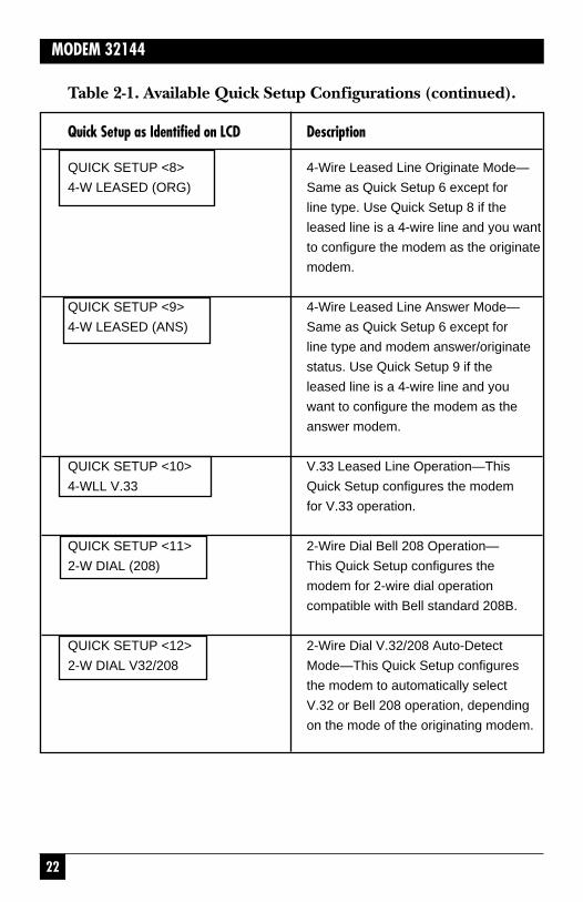
22
MODEM 32144
Table 2-1. Available Quick Setup Configurations (continued).
Quick Setup as Identified on LCD Description
QUICK SETUP <8> 4-Wire Leased Line Originate Mode—
4-W LEASED (ORG) Same as Quick Setup 6 except for
line type. Use Quick Setup 8 if the
leased line is a 4-wire line and you want
to configure the modem as the originate
modem.
QUICK SETUP <9> 4-Wire Leased Line Answer Mode—
4-W LEASED (ANS) Same as Quick Setup 6 except for
line type and modem answer/originate
status. Use Quick Setup 9 if the
leased line is a 4-wire line and you
want to configure the modem as the
answer modem.
QUICK SETUP <10> V.33 Leased Line Operation—This
4-WLL V.33 Quick Setup configures the modem
for V.33 operation.
QUICK SETUP <11> 2-Wire Dial Bell 208 Operation—
2-W DIAL (208) This Quick Setup configures the
modem for 2-wire dial operation
compatible with Bell standard 208B.
QUICK SETUP <12> 2-Wire Dial V.32/208 Auto-Detect
2-W DIAL V32/208 Mode—This Quick Setup configures
the modem to automatically select
V.32 or Bell 208 operation, depending
on the mode of the originating modem.

23
CHAPTER 2: Quick Start
Table 2-1. Available Quick Setup Configurations (continued).
Quick Setup as Identified on LCD Description
QUICK SETUP <13> 4-Wire Leased Line V.29 Mode—
4-WLL V.29 This Quick Setup configures the
modem for V.29 operation, for
compatibility with V.29 modems.
QUICK SETUP <14> V.29 Fast Master Mode—
V.29 FAST MASTER This Quick Setup configures the
modem for V.29 fast train master
operation, for use in a multidrop
network where multiple remote
(slave) modems share the master
modem as the host modem.
QUICK SETUP <15> V.29 Fast Slave Mode—
V.29 FAST SLAVE This Quick Setup configures the
modem for V.29 fast train slave
operation, for use in a multidrop
network where multiple remote (slave)
modems share the same host
(master) modem.
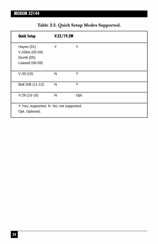
24
MODEM 32144
Table 2-2. Quick Setup Modes Supported.
Quick Setup V.32/19.2M
Hayes (01) Y Y
V.25bis (02-04)
Dumb (05)
Leased (06-09)
V.33 (10) N Y
Bell 208 (11-12) N Y
V.29 (13-15) N Opt.
Y Yes; supported. N No; not supported.
Opt. Optional;

25
CHAPTER 2: Quick Start
2.4 Basic OperationTo assist you in getting the modemup and running, the followingsections provide basic informationfor each of the modem’s primaryoperating modes. For additionaloperating information, refer to theremaining chapters in this manual.
If you encounter difficulty, referto Section 2.4 at the end of thischapter.
2.4.1 2-WIRE DIAL HAYES MODE(QUICK SETUP 1)Two-wire dial Hayes emulationmode is the factory defaultconfiguration for the modem.Hayes mode operation is explainedin detail in Chapter 5.
To dial a telephone number in Hayes mode, type the Hayescommand AT D on your computeror terminal keyboard followed bythe number you want to call. Forexample:
AT D 5551212 [CR]
Dashes or spaces may beincluded for clarity, but they arenot necessary. (The modem willignore them.) A carriage return[CR] or period is required at the end of each command line. (On most keyboards, the carriage-return [CR] key is labeled “Enter”or “Return.”) In response to thecommand line shown above, the modem will dial the number555-1212.
If you have to dial an access code such as 9 to dial out of yourbuilding, insert the access code and a comma in the dial string.
AT D 9,5551212 [CR]
The comma causes the modem to pause for 2 seconds. This allowsthe modem to detect a second dialtone (after the access code) beforedialing the number.
The default dialing mode is pulsedialing. To change to tone dialing,insert a T after AT D: AT DT. Tochange from tone dialing to pulsedialing, insert a P: AT DP. Thespecified dialing mode will remainactive until the alternate mode isspecified or the modem is reset.
When a phone number issuccessfully dialed, a “CONNECT”message will appear on thecomputer screen, and the LCDon the modem will display a statusscreen that typically look like this:
D TR MR RS CS TD9600 CD RDTD and RD will be flashing (to

26
MODEM 32144
indicate that the modem is tran-smitting and receiving data). (Thespeed may be other than 9600 bps;the modem will automaticallyadjust to the speed of the remotemodem, provided the remote unitis a compatible modem.)
To terminate a call, first enter the escape sequence +++. When theOK response appears on the DTEscreen, enter the command AT H.An alternate method is to drop theDTR signal from the DTE. If youare using a computer with acommunication software program,follow the program’s instructionsfor initiating and terminating calls.
2.4.2 2-WIRE DIAL V.25 BIS MODE(QUICK SETUP 2–4)The modem supports three types ofV.25 bis operation—asynchronous;synchronous, character-oriented; orsynchronous, bit oriented. There isa Quick Setup for each V.25 bistype, as shown in Table 2-1. ForV.25 bis operation, the modemmust be configured to use thesame data protocol (asynchronous;synchronous, character-oriented; or synchronous, bit-oriented) asthe attached DTE. If you haveselected the correct V.25 bis QuickSetup, the data protocol will be setautomatically to the correct setting.V.25 bis mode operation andcommands are explained in detail in Chapter 6.
Asynchronous V.25 bis Operation
In asynchronous applications,V.25bis commands (listed inChapter 6) may be entered fromthe DTE keyboard. As an example,the simplest command sequence isCRN 3331234. In response to thiscommand, the modem sends a VALresult code (indicating that thecommand has been accepted),dials the telephone number, 333-1234, and then waits for an answertone from a remote modem. If nocarrier is detected within a giventime (45 seconds by default), themodem automatically releases theline and sends a CFI NT result code.
Spaces entered in the commandline for readability are ignored;therefore, CRN 555 1212 will havethe same effect as CRN5551212.
The data format of the DTEshould be set to 7 data bits witheven parity and one stop bit. (Notethat the default DTE interface rateis 38,400 bps in asynchronousmode.)
When a phone number issuccessfully dialed, the EIA statusscreen on the modem will typicallylook like this:
D TR MR RS CS9600 CD
27
CHAPTER 2: Quick Start
Originating a Call from the FrontPanel
Before you can originate a callfrom the front panel, you muststore the number to be dialed inthe modem.
Storing a Number
From the EIA status screen, accessthe PHONE screen by pressing thefollowing pushbuttons in sequence:
ENTRight arrowPushbutton 1Left arrow 2 timesPushbutton 1
The abbreviations DEC, CTRL,and INC will be displayed on thebottom line of the LCD, indicatingthat you have located the PHONEscreen.
Store the phone number asfollows: Use the right and leftarrow pushbuttons to go to thedigit you want to change. Thecursor will cause the character at that digit location to blink,indicating that the digit orcharacter can be changed. Usepushbutton 1 to decrease numbersand pushbutton 3 to increase them.Use pushbutton 2 (CTRL) tosequence through the dialingcontrol characters (which areexplained in Chapter 4). Use thearrow pushbuttons to move on tothe next digit or character to bechanged. (The characters that can
Synchronous V.25 bis Operation
In synchronous applications, theV.25 bis commands can be used to facilitate computer-controlledoperations. Synchronous bit-oriented operation uses High-Level Data Link Control (HDLC)formatting. In synchronouscharacter-oriented operation,messages are framed by synchro-nous start-of-text and end-of-textcharacters, with the start-of-textcharacter preceded by twosynchronous (SY) characters.
2.4.3 2-WIRE DIAL DUMB MODE(QUICK SETUP 5)Dumb mode is used primarily for manual call origination, andanswer-only applications, and inconjunction with certain dial backsecurity systems that use MI/MICsignals to place the modem on-line.(If you need to configure themodem for MI/MIC use, refer to Appendix C.) For additionalinformation on Dumb mode, refer to Chapter 4.
Answering a Call Automatically
After the Quick Setup for 2-wiredial Dumb mode has been selected,the modem is configured toautomatically answer incomingcalls. The only other requirement isthat the DTE must provide theDTR signal (TR on the EIA statusscreen) to the modem or DTRmust be set to TRUE (using themodem’s DTR from EIA optionscreen).
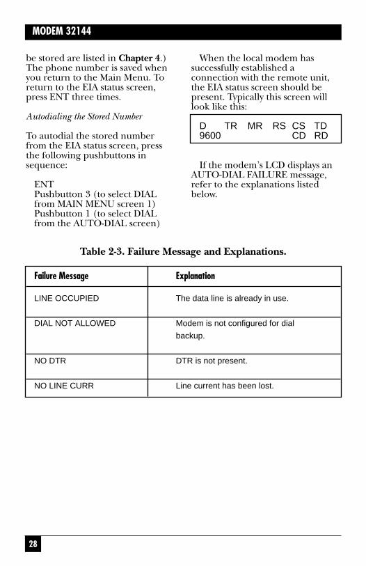
28
MODEM 32144
be stored are listed in Chapter 4.)The phone number is saved whenyou return to the Main Menu. Toreturn to the EIA status screen,press ENT three times.
Autodialing the Stored Number
To autodial the stored numberfrom the EIA status screen, pressthe following pushbuttons insequence:
ENTPushbutton 3 (to select DIALfrom MAIN MENU screen 1)Pushbutton 1 (to select DIALfrom the AUTO-DIAL screen)
When the local modem hassuccessfully established aconnection with the remote unit,the EIA status screen should bepresent. Typically this screen willlook like this:
D TR MR RS CS TD9600 CD RD
If the modem’s LCD displays anAUTO-DIAL FAILURE message,refer to the explanations listedbelow.
Table 2-3. Failure Message and Explanations.
Failure Message Explanation
LINE OCCUPIED The data line is already in use.
DIAL NOT ALLOWED Modem is not configured for dial
backup.
NO DTR DTR is not present.
NO LINE CURR Line current has been lost.

29
CHAPTER 2: Quick Start
Terminating a Data Call
Normal termination of a data call isprocessed through communicationsoftware. An alternate method is toswitch to the HANGUP option onthe AUTO-DIAL screen. Anothermethod is to drop the DTR signalfrom the DTE (by software controlor by turning the DTE off).
For manual originate/answeroperation, see Chapter 4.
2.5 Leased Line (2- or 4-Wire) Mode(Quick Setup 6–9)This section does not apply to V.33leased-line operation. For V.33leased-line operation, see the nextsection.
The following informationapplies to both 2-wire and 4-wireleased line operation:
• The modem must beconfigured for the correct linetype—2-wire or 4-wire. If youhave selected the correctLeased Line Quick Setup, the line type will be setautomatically to the correct setting.
• One modem must be set tooriginate mode and the otherto answer mode. If you haveselected the correct LeasedLine Quick Setup, theanswer/originate status will beset automatically to the correctsetting.
• Leased line operation isrestricted to data rates of 4800 bps or higher.
• Lines can be conditioned or unconditioned.
Four different leased-line QuickSetups are available (not countingV.33 leased line operation), asshown in Table 2-1. After you selectthe appropriate leased-line QuickSetup, the answer unit immediatelygenerates an answer tone thatsignals the originate modem tobegin the training sequence,meaning it is ready to “handshake”with the originate modem.
When the local modem hasestablished a connection with theremote unit, the EIA status screenshould be present. Typically thisscreen will look like this:
TR MR RS CS TD9600 CD RD
2.6 V.33 Leased Line Operation (QuickSetup 10)V.33 operation is available on themodem and is restricted to speedsof 12,000 and 14,400 bps.
V.33 leased line operationprovides compatibility with V.33modems (synchronous operationonly).
30
MODEM 32144
A 4-wire line must be used(conditioned or unconditioned),and both connected modems mustbe set for V.33 operation.
After the V.33 Leased Line Quick Setup has been selected, the modem immediately begins the training sequence, meaning itis ready to communicate with theother modem. The second modemto come online will automaticallyestablish the data link (regardlessof whether it is the local or remoteunit).
When the local modem hassuccessfully established aconnection with the remote unit,the EIA status screen should bepresent. Typically the screen willlook like this:
2.7 2-Wire Dial Bell 208 Operation(Quick Setup 11–12)The modem supports Bell 208operation. To confirm this, selectSETUP from MAIN MENU screen2. Then select QUICK from SETUPscreen 1. Press the right arrowpushbutton repeatedly to cyclethrough the Quick Setup screens. Ifyou can access the two Quick Setupscreens shown below, the unitsupports Bell 208 operation.
TR MR RS CS TD14.4 CD RD
Three options are intended forV.33 (and Bell 208A/B) operationexclusively. These options are listedin Chapter 3 under the headingV.33 and Bell 208A/B Options.

31
CHAPTER 2: Quick Start
2.8 Two Types of Bell 208 OperationTwo Bell 208 Quick Setups areavailable, as shown in Table 2-1.One configures the modem forBell 208 operation, exclusively; the other configures the modemfor V.32/208 auto-detect mode.
2.8.1 BELL 208 OPERATION(EXCLUSIVE)The Quick Setup identified on theLCD as 2-W DIAL (208) configuresthe modem for 2-wire dialsynchronous operation compatiblewith Bell standard 208B. The datarate is fixed at 4800 bps, and thedata format is set to synchronous.Both connected modems must beset for 208B operation.
Beginning with the section titled“Answering a Call Automatically,”all information in Section 2.4.3 alsoapplies to Bell 208 operation.
Fig. 2-3. Quick Setup.
QUICK SETUP <10>2-W DIAL (208)
QUICK SETUP <11>2-W DIAL V32/208

32
MODEM 32144
2.8.2 V.32/208 AUTO-SELECT MODE
The Quick Setup identified on theLCD as 2-W DIAL V32/208 (shownabove) configures the modem forV.32/208 auto-detect mode. Thismeans the modem will automati-cally select V.32 or Bell 208 mode,depending on the mode of theoriginating modem. Note that themodem will not handshake in V.22bis, Bell 212/103, or V.21/V.22/V.23 mode when it is configuredfor V.32/208 auto-detect mode.
2.9 4-Wire Leased Line V.29 Mode(Quick Setup 13)The following information appliesto 4-wire leased line V.29 operation:
• The modem must beconfigured for use with a 4-wireline. If you have selected the 4-Wire Leased Line V.29 QuickSetup, the line type will be setautomatically to the correctsetting.
• Operation is restricted to datarates of 4800, 7200, and 9600bps.
• Lines can be conditioned or unconditioned.
After you select the 4-WireLeased Line V.29 Quick Setup, the modem will send a trainingsequence and wait for a trainingresponse from the remote modem.
The modem will repeat the train-ing sequence every 1.2 secondsuntil the remote modem responds.
When the local modem hasestablished a connection with theremote unit, the TIA/EIA statusscreen will be present. Typically,this screen will look like this:
TR MR RS CS TD9600 CD RD
NOTEFor point-to-point 4-wireleased line V.29 operation,the Auto-Retrain optionshould be enabled on bothmodems. (Auto-Retrain isenabled by default if youselect the 4-Wire LeasedLine V.29 Quick Setup.) Ifthe Auto-Retrain option isdisabled, the modem will nottransmit a training sequenceand will instead train on thedata stream from the remotemodem. Disabling Auto-Retrain in 4-wire leased lineV.29 mode is recommendedfor test purposes only. IfAuto-Retrain is disabled, itshould be disabled on bothmodems.

33
CHAPTER 2: Quick Start
2.9.1 V.32 DIAL BACKUP
NOTEDial backup can only be usedin point-to-point applications.
To prevent service interruptionin case of poor leased lineconditions, the modem can beconfigured for V.29 leased lineoperation with V.32 dial backup.This means that the modem willuse dial lines to automaticallyrestore operation when conditionson the leased lines deteriorate.(The modem will use V.32modulation for dial backup.) Toset up the modem for V.29 leasedline operation with dial backup,follow these steps:
1. Select the 4-wire leased lineV.29 (4-WLL V.29) Quick Setupon both the local and remotemodem.
2. One modem must be set tooriginate mode and the otherto answer mode. To make thisselection, use the ANS/ORGDEFAULT screen on the frontpanel LCD.
3. Configure the modems forleased line auto-recovery, asexplained in Chapter 4.
2.10 V.29 Fast Master and SlaveModes (Quick Setups 14–15)
NOTEModems used in a V.29 FastMaster and Slave (multidrop)configuration must be modemsthat support V.29 operation.
In multidrop operation (Figure 2-4), the master modem transmits to all of the slave (remote) modems.When the DTE at a slave siterecognizes its own address in thepolling protocol, it raises RTS tothe slave transmitter. The slaveresponds by transmitting a specialtraining sequence, then raisingCTS and transmitting the datafrom the DTE. When the DTE hascompleted transmission, it lowersRTS and the modem will dropcarrier to let the next modem onthe poll list use the channel.
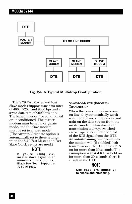
34
MODEM 32144
Fig. 2-4. A Typical Multidrop Configuration.
SLAVE-TO-MASTER (INBOUND)TRANSMISSION
When the remote modems comeon-line, they automatically synch-ronize to the incoming carrier andtrain on the data stream from themaster modem. Slave-to-mastertransmission is always switchedcarrier operation under control of the RTS signal from the DTE. An anti-streaming timer built intothe modem will (if enabled) halttransmission if the DTE holds RTSon for more than 30 seconds. Theassumption is that if RTS is held onfor more than 30 seconds, there isa fault in the DTE.
NOTESee page 176 (pump 3)to enable anti-streaming.
The V.29 Fast Master and FastSlave modes support sync data ratesof 4800, 7200, and 9600 bps and anasync data rate of 9600 bps only.The leased lines can be conditionedor unconditioned. The mastermodem must be set to originatemode, and the slave modem must be set to answer mode. (The Answer/Originate option isautomatically set to these settingswhen the V.29 Fast Master and FastSlave Quick Setups are used.)
NOTEIf you’re using V.29master/slave async in anunmanned location, callBlack Box Tech Support at724-746-5500.

35
CHAPTER 2: Quick Start
If you access the TIA/EIA statusscreen on the LCD display when aslave modem is transmitting to themaster modem, the status screenwill typically look like this:
TR MR RS CS TD9600 CD RD
Typically, TD, CD, and RD willflash on the master modem, andRS, CS, TD, and RD will flash onthe slave modem.
2.11 If You Have ProblemsIf you encounter difficulties insetting up or using the modem, trythe remedies described below. Ifyou suspect a system malfunction,follow the diagnostic proceduresdescribed in Chapter 7. If youcannot resolve the problem, callTechnical Support.
2.11.1 ALL MODES
Make sure all cables are properlyconnected to the back of themodem.
2.11.2 ALL DIAL MODES (HAYES, V.25BIS, DUMB, BELL 208, AND V.32/208)DTR (Data Terminal Ready) mustbe ON (received from DTE, orDTR from EIA option set to TRUE)if you want to use the modem’sautodial or auto-answer features. (If DTR is ON, the TR indicatorwill be present on the EIA statusscreen.

36
MODEM 32144
2.11.4 HAYES MODE
In Hayes mode, with defaultsettings in effect, the modemtransmits result codes (messages)to the DTE. In some installations,this may cause undesirableinteraction with the attached DTE.If such interaction occurs, resultcodes for incoming calls should besuppressed (using the commandAT Q2).
2.11.3 ALL ASYNCHRONOUS MODES
The modem’s default DTE speed is38,400 bps in asynchronous mode.If the local DTE does not supportthis speed, change the modem’sDTE Speed option setting. InHayes mode, the default DTEspeed is automatically overriddenwhen the modem is autobauded(when the Hayes mode “AT”attention code is sent to themodem).

37
CHAPTER 2: Quick Start
2.11.5 ALL LEASED-LINE MODES(2-WIRE, 4-WIRE, V.33, AND V.29)DTR (Data Terminal Ready) mustbe ON for the units to train on theleased line. (If DTR is ON, the TRindicator will be present on the EIAstatus screen.)
If the signal quality appears to be inadequate (see Section 7.6.2)or if the modems are frequentlyretraining, try changing theequalization option.
2.11.6 LEASED LINE (EXCLUDING V.33AND V.29 OPERATION)Make sure one modem has beenset to originate mode and that theother has been set to answer mode.(If the correct Quick Setup hasbeen selected, and not incorrectlymodified, the answer/originatestatus should be correct.)
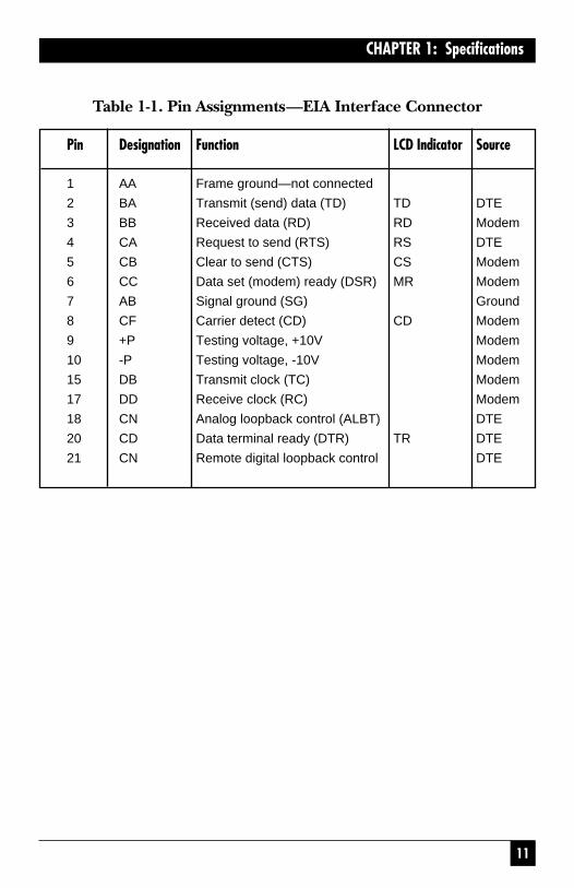
11
CHAPTER 1: Specifications
Table 1-1. Pin Assignments—EIA Interface Connector
Pin Designation Function LCD Indicator Source
1 AA Frame ground—not connected
2 BA Transmit (send) data (TD) TD DTE
3 BB Received data (RD) RD Modem
4 CA Request to send (RTS) RS DTE
5 CB Clear to send (CTS) CS Modem
6 CC Data set (modem) ready (DSR) MR Modem
7 AB Signal ground (SG) Ground
8 CF Carrier detect (CD) CD Modem
9 +P Testing voltage, +10V Modem
10 -P Testing voltage, -10V Modem
15 DB Transmit clock (TC) Modem
17 DD Receive clock (RC) Modem
18 CN Analog loopback control (ALBT) DTE
20 CD Data terminal ready (DTR) TR DTE
21 CN Remote digital loopback control DTE

12
MODEM 32144
Table 1-1. Pin Assignments—EIA Interface Connector (continued)
Pin Designation Function LCD Indicator Source
22 CE Ring indicator (RI) R Modem
23 CH Speed select DTE
24 DA External transmit clock DTE
25 CN Test mode indicator (TM) TM Modem

2
INSTRUCCIONES DE SEGURIDAD
NORMAS OFICIALES MEXICANAS (NOM)
ELECTRICAL SAFETY STATEMENT
INSTRUCCIONES DE SEGURIDAD
1. Todas las instrucciones de seguridad y operación deberán ser leídasantes de que el aparato eléctrico sea operado.
2. Las instrucciones de seguridad y operación deberán ser guardadaspara referencia futura.
3. Todas las advertencias en el aparato eléctrico y en sus instrucciones de operación deben ser respetadas.
4. Todas las instrucciones de operación y uso deben ser seguidas.
5. El aparato eléctrico no deberá ser usado cerca del agua—por ejemplo,cerca de la tina de baño, lavabo, sótano mojado o cerca de unaalberca, etc.
6. El aparato eléctrico debe ser usado únicamente con carritos opedestales que sean recomendados por el fabricante.
7. El aparato eléctrico debe ser montado a la pared o al techo sólo como sea recomendado por el fabricante.
8. Servicio—El usuario no debe intentar dar servicio al equipo eléctricomás allá a lo descrito en las instrucciones de operación. Todo otroservicio deberá ser referido a personal de servicio calificado.
9. El aparato eléctrico debe ser situado de tal manera que su posición nointerfiera su uso. La colocación del aparato eléctrico sobre una cama,sofá, alfombra o superficie similar puede bloquea la ventilación, no sedebe colocar en libreros o gabinetes que impidan el flujo de aire porlos orificios de ventilación.
10. El equipo eléctrico deber ser situado fuera del alcance de fuentes de calor como radiadores, registros de calor, estufas u otros aparatos(incluyendo amplificadores) que producen calor.
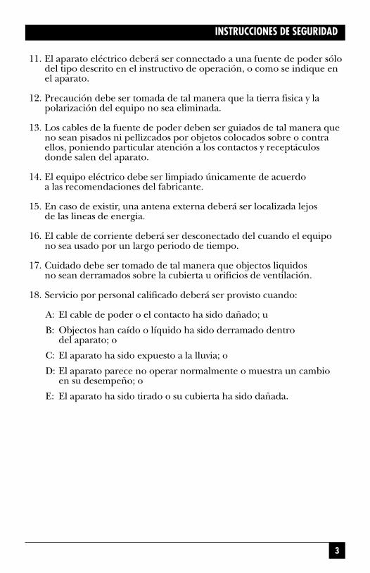
3
INSTRUCCIONES DE SEGURIDAD
11. El aparato eléctrico deberá ser connectado a una fuente de poder sólodel tipo descrito en el instructivo de operación, o como se indique enel aparato.
12. Precaución debe ser tomada de tal manera que la tierra fisica y lapolarización del equipo no sea eliminada.
13. Los cables de la fuente de poder deben ser guiados de tal manera queno sean pisados ni pellizcados por objetos colocados sobre o contraellos, poniendo particular atención a los contactos y receptáculosdonde salen del aparato.
14. El equipo eléctrico debe ser limpiado únicamente de acuerdo a las recomendaciones del fabricante.
15. En caso de existir, una antena externa deberá ser localizada lejos de las lineas de energia.
16. El cable de corriente deberá ser desconectado del cuando el equipono sea usado por un largo periodo de tiempo.
17. Cuidado debe ser tomado de tal manera que objectos liquidos no sean derramados sobre la cubierta u orificios de ventilación.
18. Servicio por personal calificado deberá ser provisto cuando:
A: El cable de poder o el contacto ha sido dañado; u
B: Objectos han caído o líquido ha sido derramado dentro del aparato; o
C: El aparato ha sido expuesto a la lluvia; o
D: El aparato parece no operar normalmente o muestra un cambio en su desempeño; o
E: El aparato ha sido tirado o su cubierta ha sido dañada.

4
TRADEMARKS
TRADEMARKS
All applied-for and registered trademarks are the property of theirrespective owners.
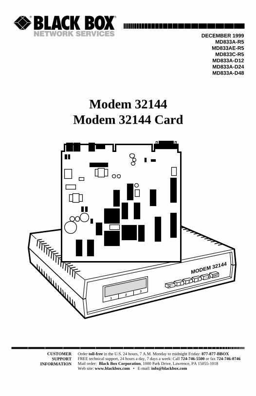
CUSTOMERSUPPORT
INFORMATION
Order toll-free in the U.S. 24 hours, 7 A.M. Monday to midnight Friday: 877-877-BBOXFREE technical support, 24 hours a day, 7 days a week: Call 724-746-5500 or fax 724-746-0746Mail order: Black Box Corporation, 1000 Park Drive, Lawrence, PA 15055-1018Web site: www.blackbox.com • E-mail: [email protected]
DECEMBER 1999MD833A-R5
MD833AE-R5MD833C-R5
MD833A-D12MD833A-D24MD833A-D48
Modem 32144Modem 32144 Card
MODEM 32144
➝
➝1
23
ENT
12
3