1 electron diffraction —...
TRANSCRIPT
1 electron diffraction — Introduction
The purpose of this laboratory is to observe the wave nature of the ectron, and to
measure the the two lattice spacings in graphite.
Please read the attached notes.
1

,
-<
•
•
• EXPERIMENT 7
Electron D action
Objective
To observe the wave like properties of the electron.
References
Wehr, Richards and Adair, Physics of the Atom, 7.4, Sproull, Modern Physics, 4-10 •
1 Introduction ,
The wave character of elecbo-magnetic radiation can be demonstrated by observation of diffraction effects with microwaves or through other elementary optics . Briefly, if a pair of narrow slits, separated by a distance d, in an opaque screen is illuminated with plane waves of coherent light of wavelength ..\ incident normal to the sucen , the transmitted light is scen to have intensity maxima due to constructive interference at angles 9 (rdative to the ) which satisfy the condition
d 9 = n..\ n = 0,±1,±2,... (1)
where the integer n is called the order number. The anguJar width (FWH M) of these is 59 = sin-l(..\j(2cl)). If the number of slit. is to N while the same
.Q.' d, the at which these maxima are seen . the same, the primary . being that the widthJ of the maxima becoming 59 = sin-l("\/(Ncl)). In the ofvcry large N, these widths become exotremely narrow and the device (a . grating) serves as a analyzer". That is, the incident light is "dispersed" into a spectrum with high resolution, For simplicity, only the first-order spectrum (n = 1) will be considered in the following.
The best man-made gratings are ruled with 2000 lines (slits) per mm, which conesponds to a slit ' of d = 5 X 10⁻⁴ mm = 500 urn (attempts.-to obtain a run into the problem of the_ gran of matter itself). If x-rays of wavelength O.O~ urn
- ---
1 .
•
•
•

•
• •
•
•
•
•
•
are diffracted by such a grating, the angle of the first order maximnm is 8 ~ sin 8 = >../ d = 0.02/500 = 4 x 10⁻⁵ rad, causing a displacement of only 0.4 urn on a screen placed 10 m from the grating. Clearly, a man-~ade grating is not a good instrument to use in the study of x-ray spectra •
.....
-e-
Figure 1: Schematic illustration of re1lection
In 1912, Prof. Max von Laue suggested that, if the granularity of matter the of gratings suitable for x-ray studies, perhaps this very in itself
•
provide _a suitable Sir Lawrence Bragg then calculated the interatomic . for a cubic crystal of NaCl and showed them to be of the right order to serve as a suitable grating for x-rays. Thus began the scientific field of x-ray crystallography. The proces. is illustrated schematically in Fig. 1, in which two planes (called . planes) of a crystal are shown. The dots are scattering centers (atoms). The pathlength . for incident waves scattered from the two different planes is 2d sin 8. H this distance it an integer num ber of wavelength. there will be constructive interference. This is known as Law:
2d sin 8 = n>.., n = 1,2,3, .... (2)
The similarity to Eq. 1 is noteworthy, but this is actually a different , because 8 has a different meaning in this case. Note that the angle of deflection of the x-raya (or electrons) is 28.
In a cubic crystal such as NaCl (table salt), it is possible to construct many of Bragg planes, as is in Fig. 2a, each corresponding to a different angle of de1lection. H polychromatic x-rays are incident upon a single crystal of NACL, the reflected x-rays a pattern of spots known as the von Laue spot pattern (see Fig. 3b). When the •
lIa
2
•

I
-
• ,
• powder, it contains very many crystals with random orientations and the pattern becomes a sene. of rings.
,
. a·· · · · .' .. · · .. .......... • • • • • • • •
• • • • • • • •
I
• ••• • • • • •
•
• • • • • • • • • • • • •
• ••••• • • • • • • • • • ... . ., ..
• •••••• • • • • • • • • • .. ... • • .......:.~:::::;?:'
• • • • • • • • • • ,
• • • • • •
• • ._-
• • • • • •
• • • • ... ~~:;;,
• • • • • • • • • • • • • • • . . . . . . . . . . ~ . . . .
•
b
•
•
•
2: (a) Fami1ies of Bragg planes in a cubic crystal of NaCl. The x-ray. incideut from the left are to be polychromatic. The rdlected are (b ) The von Laue spot pattern when a single crystal of NaCl is by polychromatic x-rays. The bright central spot has been blocked by an opaque disk.
Since NaCl is unsuitable for use in a vacuum, the target used in the present is - -polycrysta11ine carbon (graphite). The interatomic may be estimated by noting that 12 grams of carbon contains Avogadro's number (No = 6.02 X 10²¹) of C atom •• Since the density p of graphite is 2.25 g/cm3, the number of C atoms per 3 is pNolA = 2.25 X 6.02 X
1021 /12 = 1.13 X 10²¹ • The reciJ>ro~al of this number would be the volume per carbon atom, and on the assumption that the atom is a cube (not actually true, but useful for purposes of estimation), its side length would be {1.13 X 10²¹)-1/3 = 2.07 X 10-l cm = 0.207 nm. The
3
, -
•

•
• •
• •
•
•
• crystal structure of carbon is actually hexagonal, &II shown in Fig. 3. Note that two differellt sets of Bragg pJanes are shown, with different interatomic spacings, diG = 0.213 nm and du = 0.123 nm.
•
•
• •
,
•
Figure 3: lattice of graphite. (a) Two dimensional view, the two planes. (b) Three-dimensional (isometric) view, showing a cell" which two atoms.
Figure 3b shows two planes of the graphite lattice in an isometric perspective . Note the arrangement of carbon atoms parallel to the x-y plane, and the rectangular arrangement perpendicuJar to it. The parallelopiped (rhomboid) indicated is a nnit cell. It h&ll faces parallel to the x-y plane, at distances +b/2 -b/2 from it. The corners of the box are at the centers of neighboring hexagons. nnit cell contains two carbon atoms (black spots). From the results of this experiment, we can calculate the hexagon side-length a, and from this we calculate the area A of the (which is . the same &II the projected area of a nnit cell in the x-y plane). But the volume V of the unit cell is b A, and thus the volume occupied per carbon atom is V /2= b A/2. The product of
4
•
,

/
•
•
•
•
•
•
I
-•
,
•
I ~ , ~ / \ \
.J •
..-,
'-1
this vol11me and the BlJmber N of carbon atoms per cm3 is lem3 = 10-8m 3 = bAN/2. Since b is the only unknown quantity, we can solve for it, and thus determine the ..uJ.'
the hexagonal planes. . In 1926, Loui. de Broglie hypothesized that particles could have wave characteristic. with
a given by -
A =h/p • (3)
where h i. Planck'. constant and p is the momentum of the particle. If so, electrons incident upon a crystalsh~uld show the same kind of djffraction effects already with x-ray •. The verification o{this hypothesis was tr-;iJy a remarkable turn of events in the history of modern physics.
In other experiments, the charge-mas. ratio elm of the electron can be (e/m = 1.76 x 10¹¹ and the electron charge e can be determjned (e = 1.60 x 10⁻¹"0). Thus, the electron m is known (m = 9.11 x 1O-31kg). The value of hie (h/e = 4.14 x 10-lI J ~ec/C) be comoined with e to determine Planck's constant (h = 6.63 x lO-M J sec). If an electron is accelerated through a potential difference V it gajns kinetic energy K = V e, and (neglect-ing small relativistic corrections) it momentum p = v'2mK = v'2m Ve. This . be combined with Eq. 3 to yield
A = h = _ ~==:::::=:::====6.63 x 10⁻³⁴
v'2m Vex x =x=?"=::= X
1.228 = v'V nm (4)
-From Eq. 2 (with n = 1), diffraction effect. will be seen if. d_is about lOA. If dis
:::::: 0.2 nm as was estimated for carbon, the corresponding value of A would be ~ 0.02 nm. As may be calculated with Eq. 4, this corresponciJ to V = (1.228/0.02)2 = 3770 V, a voltage easily obtained in the laboratory. Therefore, this presents with a simple way of interatomic '. If a lluorescent is a L from the target and the first order . maximum is seen at r from the center of the in the small angle approximation ( sin 8 ::::::-8 :::::: 8) the angle is :::::: 28 ==r fL. Thus 8 ~ r/2L, Bragg's Law (for n = 1) becomes A =-2cl8 = 2dr/2L = dr is combined with Eq. 4, it is that
,
d( ) _ 1.228£ . L 1
nm - ITT r.v V
, j \
where L and r are measured in the same units. . ../
I
/
/
c ' I •
•
• .
(5)
. ~ , . •
• • •
•
•
.. , -
-
• -
•
, •
•
'GWI' •
t
4 ..
I. +
- •
, - •
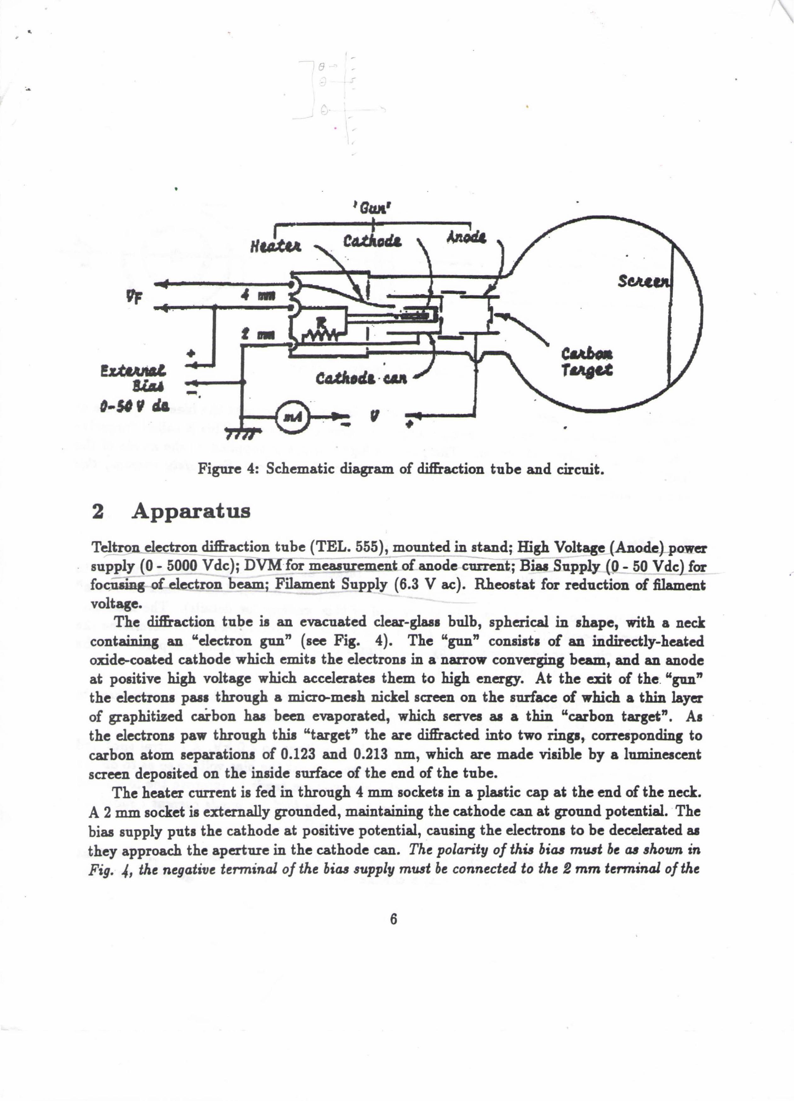
Figure 4: Schematic diagram of diffraction tube and circuit.
2 Apparatus
tube (TEL. 555), mounted in . High Voltage (Anode}.-power supply (0 -_5000 Vdc); DVM for _ of anode - Supply (0_- 50 Vdclfor fOCJlsing- o£..dectron beam; Filament Supply (6.3 Vac). Rheostat for red of fllament voltage.
The diffraction tube ia an evacuated clear-glass bulb, spheical in shape, with a neck "electron gilD" (see Fig. 4). The "glln" consists of indirectly-heated
oxide-coated cathode which emits the electrons in a narrow converging and anode at positive high voltage which accelerates them to high energy. At the exit of the. "gon" the electrons paas through a micro-mesh nickel screen on the of which a thin layer of graphitized c.a.Tbon haa been evaporated, which servea aa a thin "carbon target". As the electrons paw through thia "target" the are djffracted into two rings,. coneaponding to carbon atom separations of 0.123 0.213 nm, which are made visible by a ]nmjneacent screen deposited on the inside surface of the end of the tube.
The heater current is fed in through 4 mm sockets in a plastic cap at the end of the neck. A 2 mm socket is externally gronnded, maintaining the cathode can at gronnd potential . . The bias supply puts the cathode at positive potential, causing the electrons to be decelerated as they approach the aperture in the cathode The polarity of thi. bia. mu.d be a. ,hown in Fig. 4, the negative teM"inal of the bia. supply must be connected to the 2 mm terminal of the
6
•
•
•
,
•
•
•
•
•
•
. ----------- -
L • •
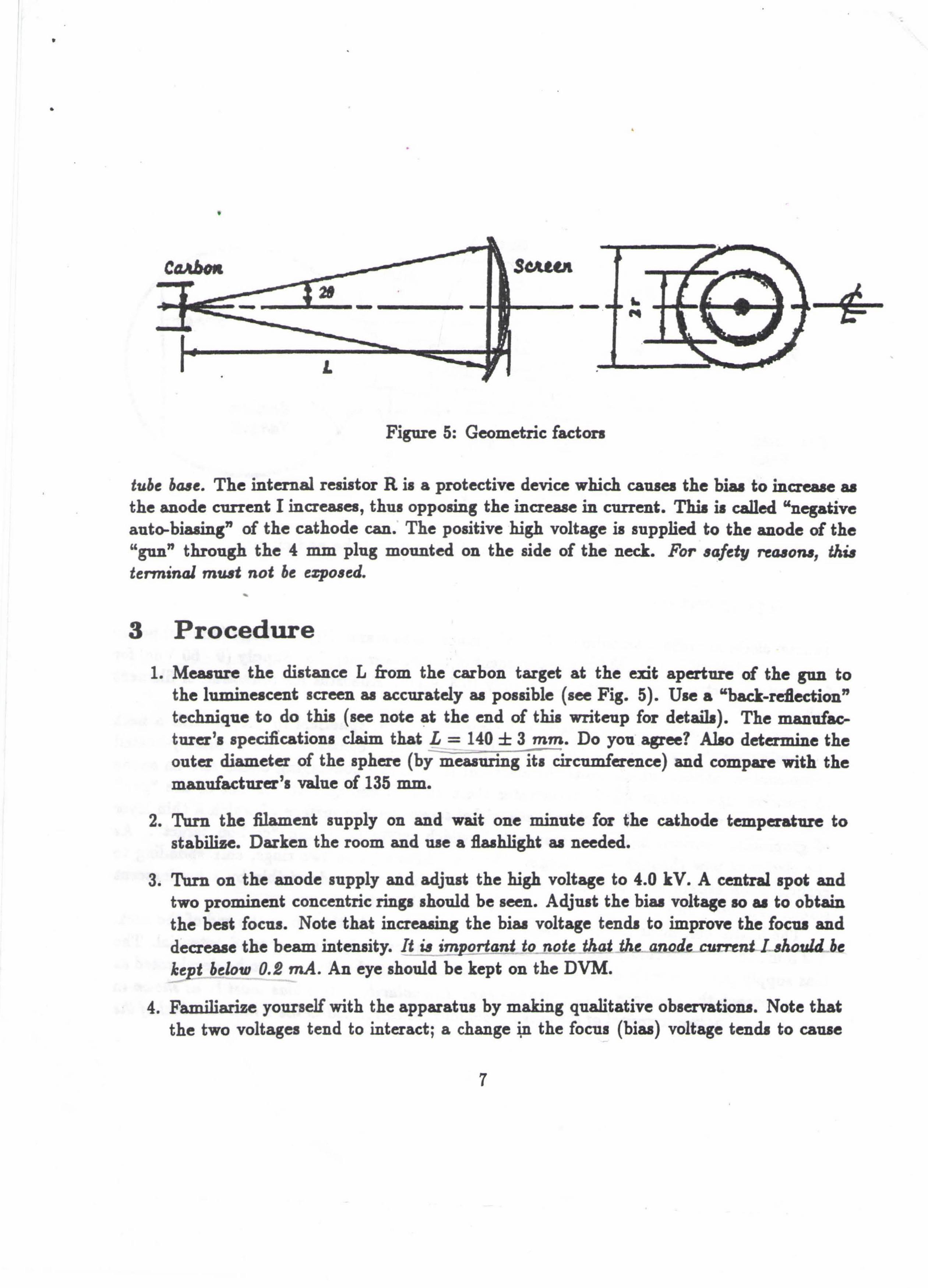
Figure 5: Geometric factors
•
.. ...
tube b48e. The internal resistor R is a protective device which causes the to . aa the anode current I increases, thus opposing the· in current. Thi, is called "negative auto-·· of the cathode . The positive high voltage is supplied to the of the "glln" through the 4 mm plug mounted on the side of the neck. For 6afety 1'e480fU, thu tet1ninal mu.tt not be ezp06ed.
3 Procedure
1. the L from the carbon target at the exit aperture of the glln to the as accurately as possible (see Fig. 5). Use a " technique to do this (see note at the end of this wliteup for details). The turer's specmcations claim that L = 140 ± 3 mm. Do you agree? determine the
~ - ... - -. :
outer diameter of the sphere (by measuring its circnmfetence) and compare with the value of 135 mm.
2. Turn the filament supply on and wait one minute for the cathode tcmpetatare to stabi1i~. Darken the room and use a flashlight as needed.
3. Turn on the anode supply and adjust the high voltage to 4.0 kV. A ulitralspot and two prominent concentric rings should be seen. Adjust the bias voltage 10 81 to obtain the best focus. Note that increasing the biu voltage tends to improve the focus and
the beam intensity. It u im ortant to not~ that the_lW.JJ.de CUD"~nt 1 ~houLlbe ke t below 0.2 mAo An eye should be kept on the DVM. ~
. 4. Fami1iarize yourself with the apparatus by making qualitative observations. Note that the two voltages tend to interact; a change i:n the focus (bias) voltage tends to cause
7
•
• . ,

•
• • "
•
•
•
•
• a change in the anode voltage. Alao, at a given anode voltage, the ring diameters should not change u the focus voltage is changed, but this is not always true; at the lower anode voltages, the ring diameters may increase u the foclll voltage is
the intensity. The explanation of this is that space charge effects (i.e., mutual Coulomb repulsion of the electrons) give added de:flection to the electrom. This is to be avoided. It also should be noted that . . ' the focus voltage tends to the beam and is a good way to keep below it
to keep the beam current u small u possible, consistent with making the required This will prolong the life of the tube.{It may be necessary to
the filament voltage in order to keep the filament current below this limit.) Finally, note thai u the anode voltage is varied the diameters of the rings ..,u.
the bias voltage also needs to be adjusted.
5. At anode voltage 2.0 kV, adjust the focus and use a to the diameter of each ring u accurately u possible. In order to accuracy, the ring diameter should be extrapolated u shown in Fig. 6, in order to compellsate for both the curvature and thickness of the glass envelope. This is most at low anode- voltages for which the ring cliameters are largest.
1.5 _ , •. , ..
•
•
•
L •
•
Figure 6: Determination of extrapolated radii
6. Repeat the measurements of Step 4 at 500 V intervals, up to 5 kV. At each anode voltage, adjust the focus and make sure that the anode current stays below 0.2 mA (it will increase u the anode voltage is increased; if it approaches that limit, increase the focus voltage or if that is not feasible, decrease the filament voltage before continuing).
8
•
•
•
•
• •
•
•
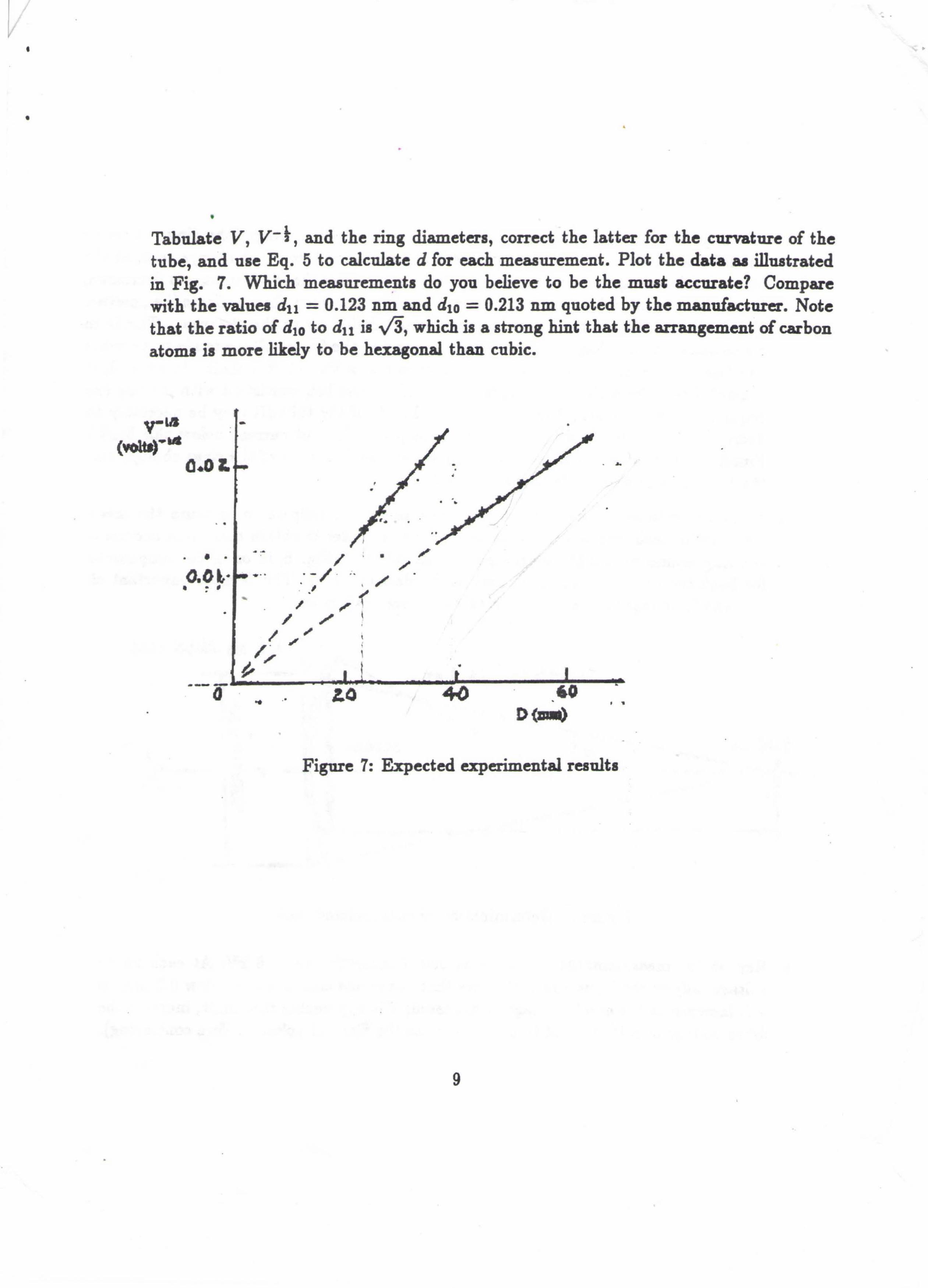
• Tabulate Y, y-t, and the ring , correct the latter for the curvature of the tube, and use Eq. 5 to calculate d for each measurement. Plot the data as illustrated in Fig. 7. Which . do you believe to be the must accurate? Compare with the values dll = 0.123 nm and diG = 0.213 nm quoted by the . Note that the ratio of d1G to dll is vta, which is a strong hint that the of carbon atoms is more likely to be hexagonal than cubic.
- •
•
0.01. • •
•
•
• • •
••• O.Ol." / . . /' /
. - / .. . . , , /' ,,' ,,'(
/ /' \ •
• • • • . -
• •• •
•
/ '" \ / . ", ; "II" •
.. .' • •
•
Figure 7: Expected exoperimental results
•
9
• •
•

~ . •
•
c
y y-
(volts ,
2000 0.0224 •
2500 0.0200 3000 0.0183
,
3500 0.0169 • 4000 0.0158
4500 0.0149 II 5000 0.0141
•
• , • \) -1 \
.-
l D(nun)
• • outer ring TI Inner nng •
15, o~ 0 :l.S,81~
\ L , 2-& Z' ~.Lt,15h
1., ,t:; rl 2~ l):'
l}. ,2~ 2?'~c ~ I .
2..100 ·11
\ 1., bl .
.
\ q.~ - ~? -<.: b 0
,2 , 2. ~I I \ ' 4-0 g - i)
•
10
•
I VI'
I, 'lAJ)
(). '1';t;5 i' 002 3 1,/7 1
o /1':J.c2 '.,7.J) ~ I UbS
•