1 directional antennas in ad hoc networks nitin vaidya university of illinois at urbana-champaign...
TRANSCRIPT
1
Directional Antennasin
Ad Hoc Networks
Nitin Vaidya
University of Illinois at Urbana-Champaign
Joint work with
Romit Roy Choudhury, UIUC
Xue Yang, UIUC
Ram Ramanathan, BBN
2
Mobile Ad Hoc Networks
Formed by wireless hosts which may be mobile
Without necessarily using a pre-existing infrastructure
Routes between nodes may potentially contain multiple hops
3
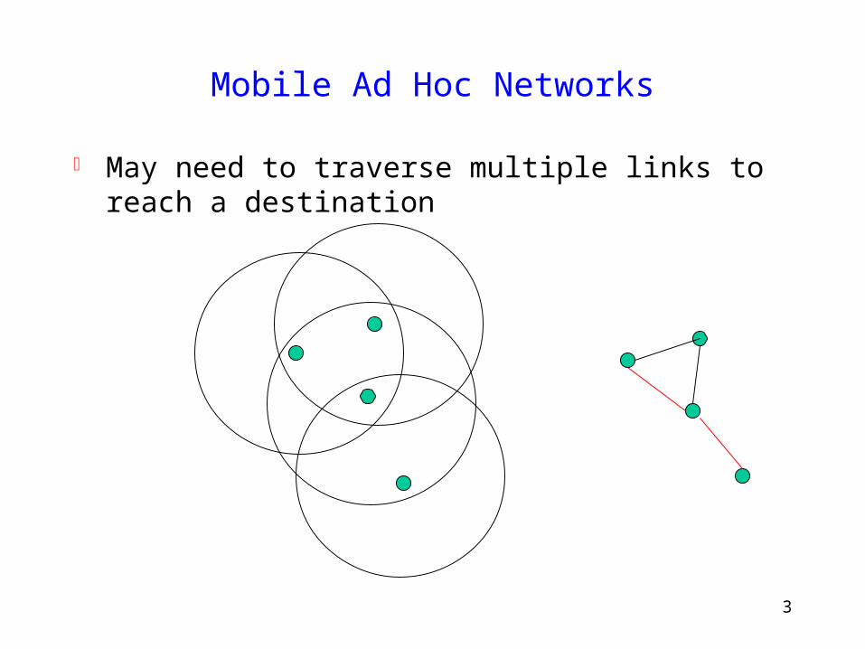
Mobile Ad Hoc Networks
May need to traverse multiple links to reach a destination
4
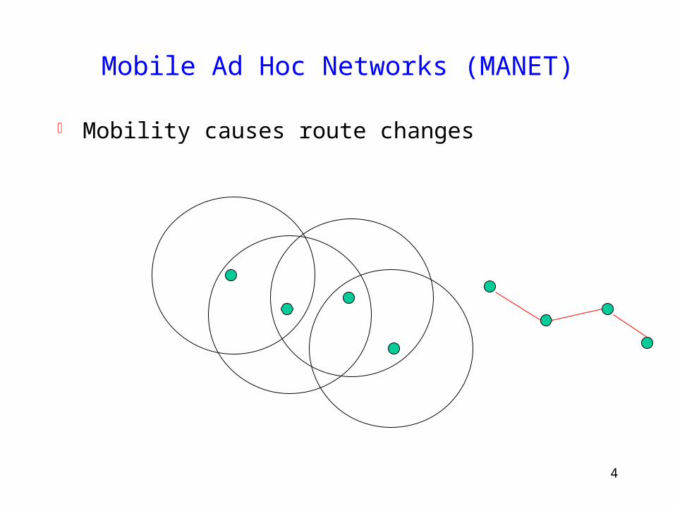
Mobile Ad Hoc Networks (MANET)
Mobility causes route changes
5
Why Ad Hoc Networks ?
Potential ease of deployment
Decreased dependence on infrastructure
6
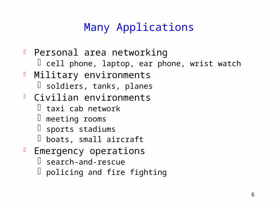
Many Applications
Personal area networking cell phone, laptop, ear phone, wrist watch
Military environments soldiers, tanks, planes
Civilian environments taxi cab network meeting rooms sports stadiums boats, small aircraft
Emergency operations search-and-rescue policing and fire fighting
7
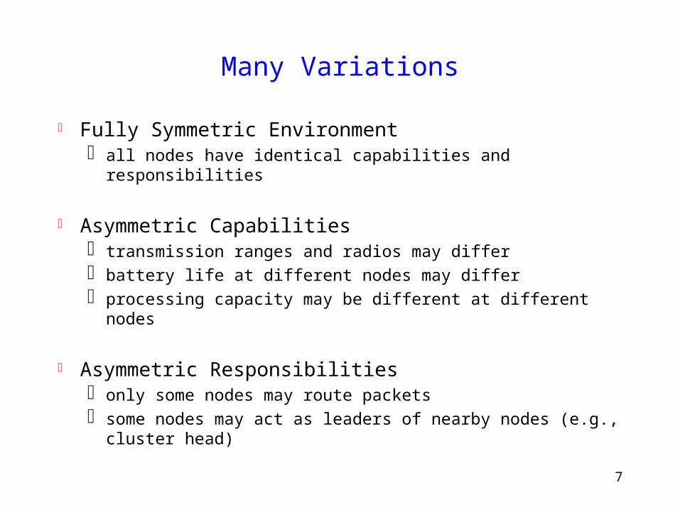
Many Variations
Fully Symmetric Environment all nodes have identical capabilities and responsibilities
Asymmetric Capabilities transmission ranges and radios may differ battery life at different nodes may differ processing capacity may be different at different nodes
Asymmetric Responsibilities only some nodes may route packets some nodes may act as leaders of nearby nodes (e.g.,
cluster head)
8
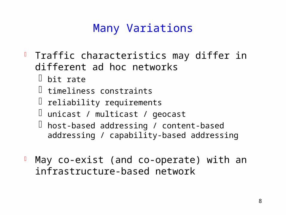
Many Variations
Traffic characteristics may differ in different ad hoc networks bit rate timeliness constraints reliability requirements unicast / multicast / geocast host-based addressing / content-based addressing /
capability-based addressing
May co-exist (and co-operate) with an infrastructure-based network
9
Many Variations
Mobility patterns may be different people sitting at an airport lounge New York taxi cabs kids playing military movements personal area network
Mobility characteristics speed predictability
• direction of movement
• pattern of movement uniformity (or lack thereof) of mobility characteristics among
different nodes
10
Challenges
Limited wireless transmission range Broadcast nature of the wireless medium
– Hidden terminal problem Packet losses due to transmission errors Mobility-induced route changes Mobility-induced packet losses Battery constraints Potentially frequent network partitions Ease of snooping on wireless transmissions (security
hazard)
11
Question
Can ad hoc networks benefit from the progress made at physical layer ?
Efficient coding schemes Power control Adaptive modulation Directional antennas …
Need improvements to upper layer protocols
12
Directional Antennas
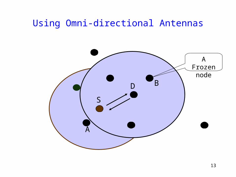
13
Using Omni-directional Antennas
A Frozen node
S
D
A
B
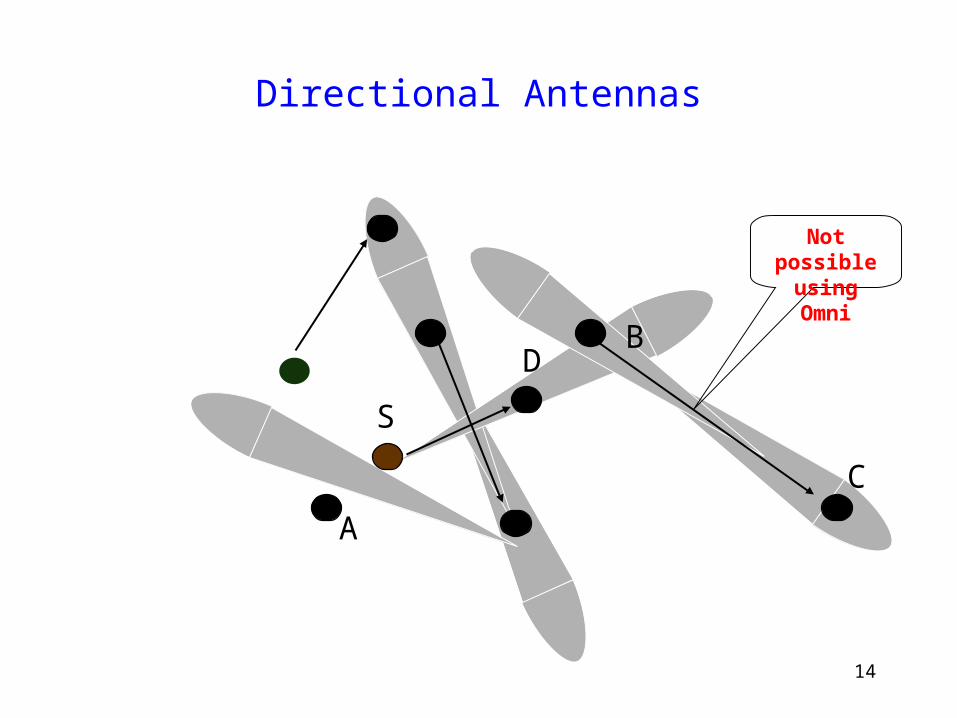
14
Directional Antennas
Not possible using Omni
S
D
A
B
C
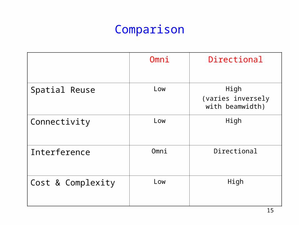
15
Comparison
Omni Directional
Spatial Reuse Low High
(varies inversely with beamwidth)
Connectivity Low High
Interference Omni Directional
Cost & Complexity Low High
16
Questions
Are Directional antennas beneficial in ad hoc networks ?
To what extent ?
Under what conditions ?
17
Research Direction
Identify issues affecting directional communication
Evaluate trade-offs across multiple layers
Design protocols that effectively use directional capabilities
Caveat: Work-in-Progress

18
Preliminaries
19
A B C
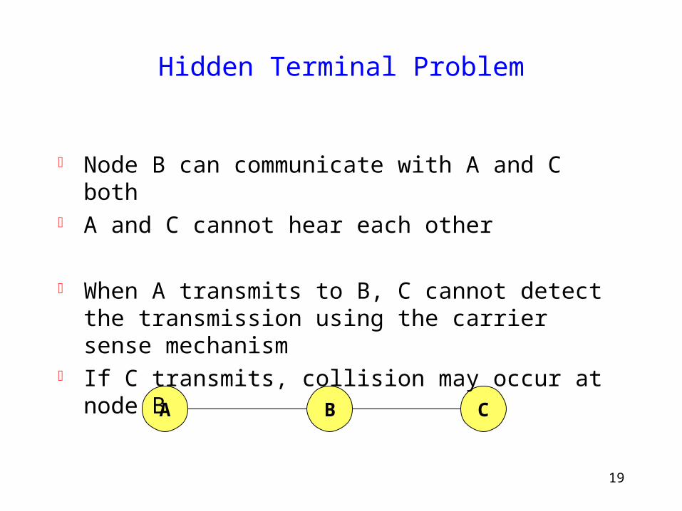
Hidden Terminal Problem
Node B can communicate with A and C both A and C cannot hear each other
When A transmits to B, C cannot detect the transmission using the carrier sense mechanism
If C transmits, collision may occur at node B
20
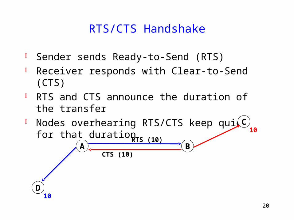
RTS/CTS Handshake
Sender sends Ready-to-Send (RTS) Receiver responds with Clear-to-Send (CTS) RTS and CTS announce the duration of the transfer Nodes overhearing RTS/CTS keep quiet for that
duration
D
C
BACTS (10)
RTS (10)
10
10
21
IEEE 802.11
Physical carrier sense Virtual carrier sense using Network Allocation Vector
(NAV) NAV is updated based on overheard
RTS/CTS/DATA/ACK packets, each of which specified duration of a pending transmission
Nodes stay silent when carrier sensed busy (physical/virtual)
22
Antenna Model
23
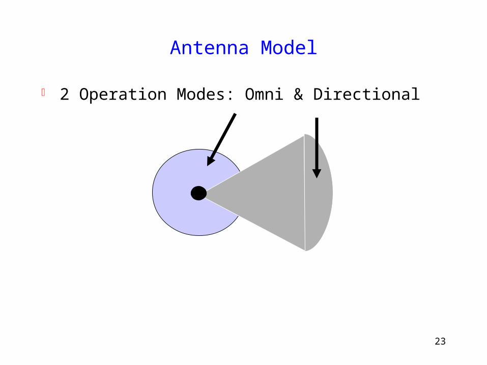
Antenna Model
2 Operation Modes: Omni & Directional
24
Antenna Model
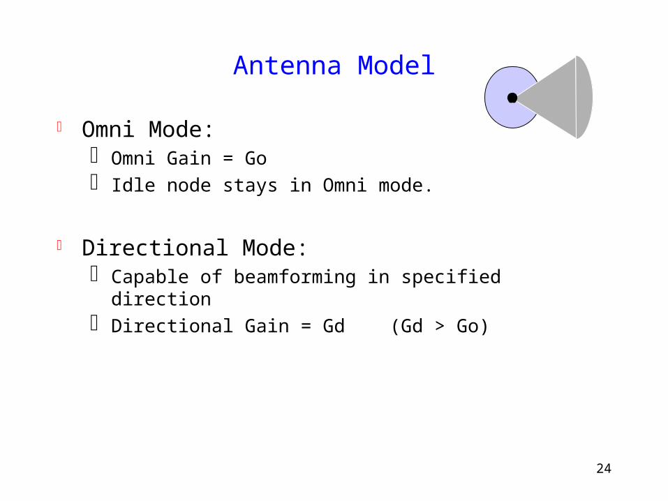
Omni Mode: Omni Gain = Go Idle node stays in Omni mode.
Directional Mode: Capable of beamforming in specified direction Directional Gain = Gd (Gd > Go)
25
C
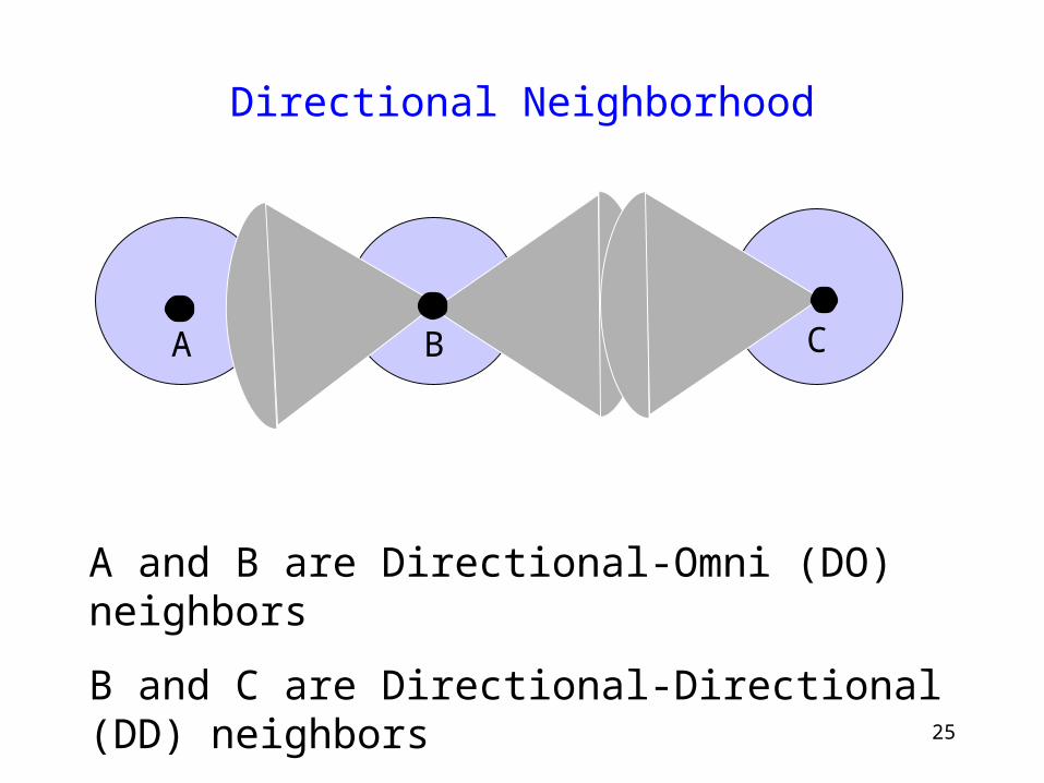
Directional Neighborhood
B
A
A and B are Directional-Omni (DO) neighbors
B and C are Directional-Directional (DD) neighbors
26
A Simple Directional MAC Protocol(DMAC)
27
DMAC Protocol
A node listens omni-directionally when idle Only DO links can be used
Sender node sends a directional-RTS using specified transceiver profile
Receiver of RTS sends directional-CTS
28
DMAC Protocol
DATA and ACK transmitted and received directionally
Nodes overhearing RTS or CTS sets up NAV for that DOA (direction of arrival)
Nodes defer transmitting only in directions for which NAV is set
29
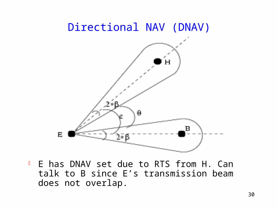
Directional NAV (DNAV)
Node E remembers directions in which it has received RTS/CTS, and blocks these directions.
Transmission initiated only if direction of transmission does not overlap with blocked directions.
30
Directional NAV (DNAV)
E has DNAV set due to RTS from H. Can talk to B since E’s transmission beam does not overlap.
31
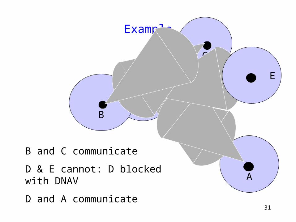
Example
B
C
A
D
E
B and C communicate
D & E cannot: D blocked with DNAV
D and A communicate
32
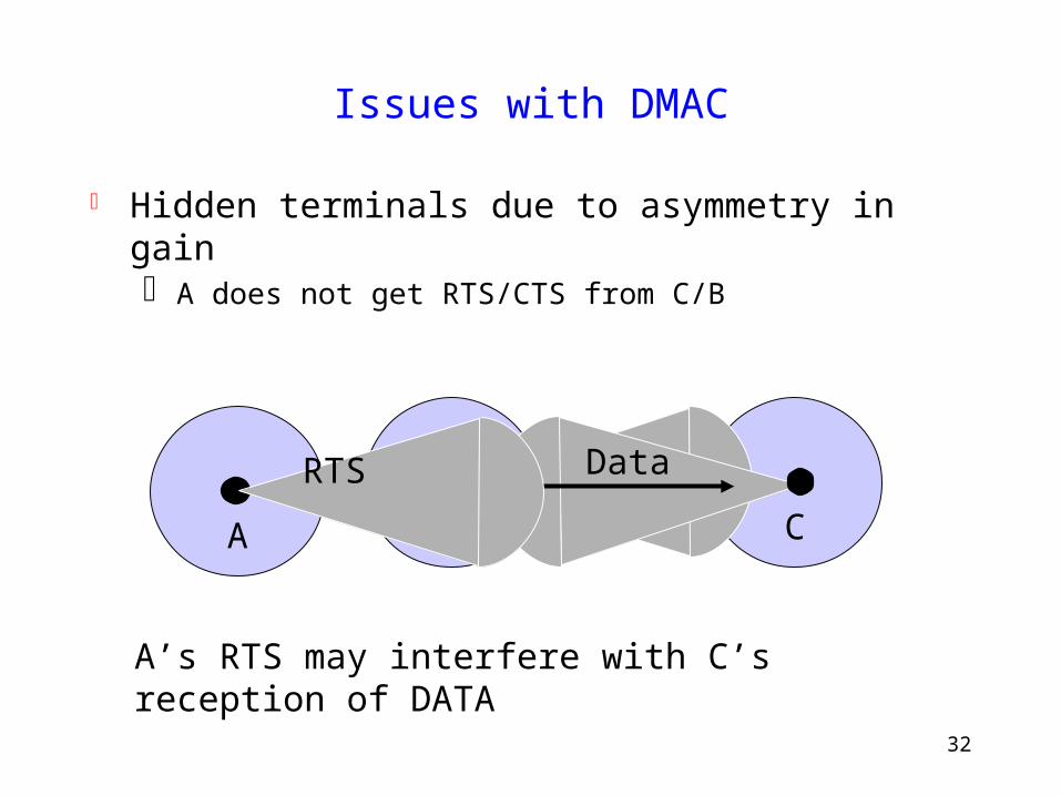
Issues with DMAC
Hidden terminals due to asymmetry in gain A does not get RTS/CTS from C/B
C
A B
DataRTS
A’s RTS may interfere with C’s reception of DATA
33
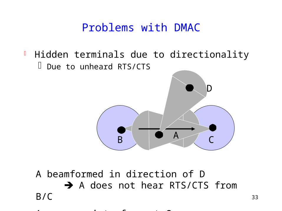
Problems with DMAC
Hidden terminals due to directionality Due to unheard RTS/CTS
CB
A beamformed in direction of D A does not hear RTS/CTS from B/C
A may now interfere at C
D
A
34
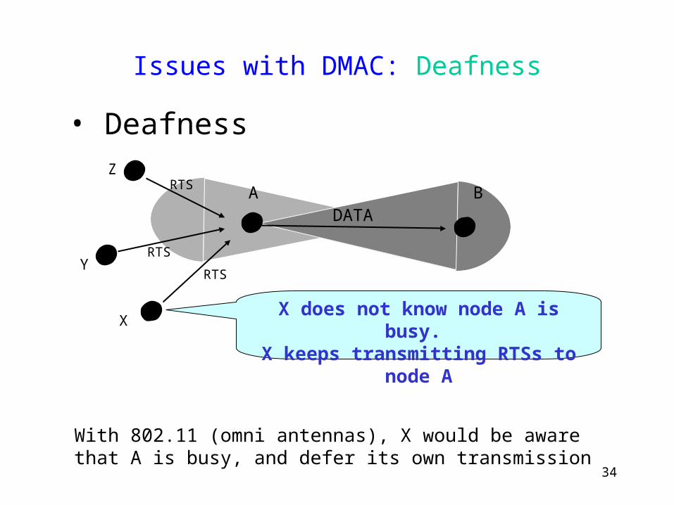
Issues with DMAC: Deafness
RTS
RTS
RTS
DATA
X does not know node A is busy. X keeps transmitting RTSs to node A
A B
With 802.11 (omni antennas), X would be aware that A is busy, and defer its own transmission
X
Z
Y
• Deafness
35
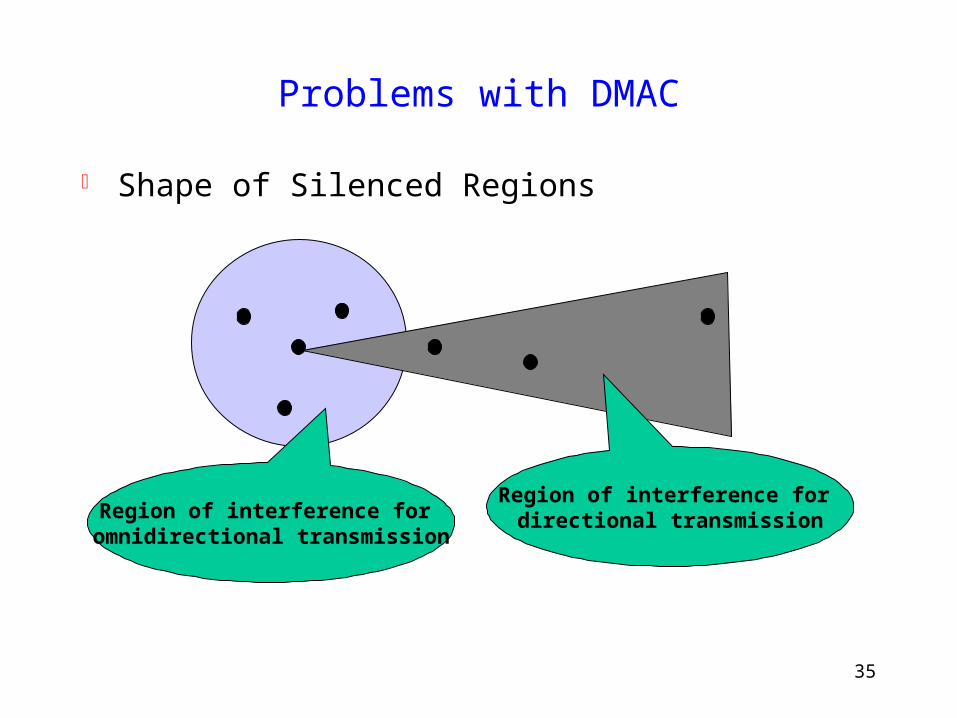
Problems with DMAC
Shape of Silenced Regions
Region of interference for directional transmissionRegion of interference for
omnidirectional transmission
36
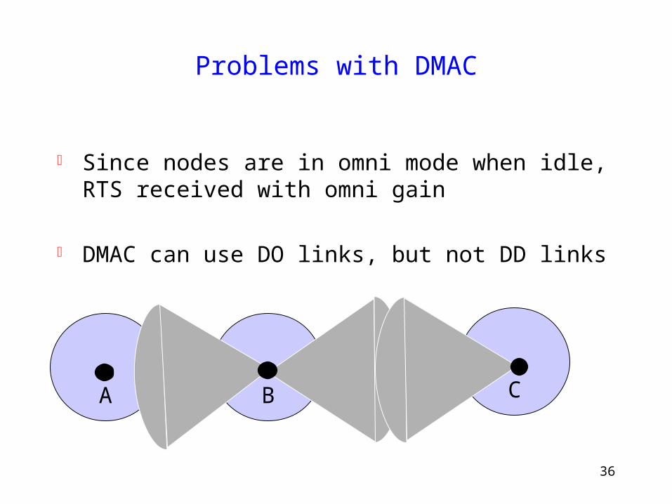
Problems with DMAC
Since nodes are in omni mode when idle, RTS received with omni gain
DMAC can use DO links, but not DD links
CB
A
37
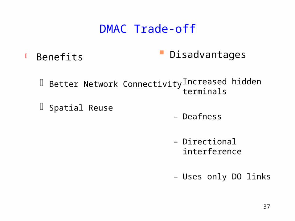
DMAC Trade-off
Benefits
Better Network Connectivity
Spatial Reuse
Disadvantages
– Increased hidden terminals
– Deafness
– Directional interference
– Uses only DO links
38
Solving DMAC Problems
Are improvements possible to make directional MAC protocols more effective ?
One possible improvement: Use DD links
39
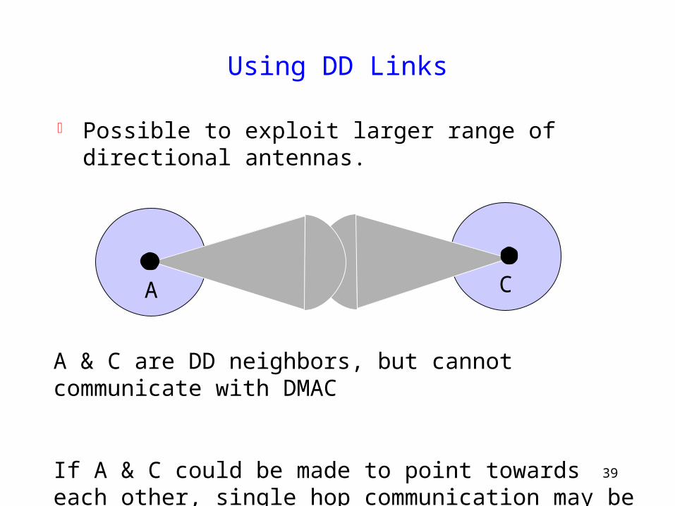
Using DD Links
Possible to exploit larger range of directional antennas.
C
A
A & C are DD neighbors, but cannot communicate with DMAC
If A & C could be made to point towards each other, single hop communication may be possible
40
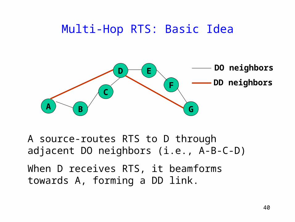
Multi-Hop RTS: Basic Idea
A B
C
D E
F
G
DO neighbors
DD neighbors
A source-routes RTS to D through adjacent DO neighbors (i.e., A-B-C-D)
When D receives RTS, it beamforms towards A, forming a DD link.
41
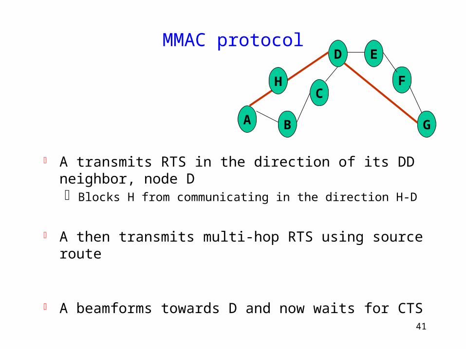
MMAC protocol
A transmits RTS in the direction of its DD neighbor, node D Blocks H from communicating in the direction H-D
A then transmits multi-hop RTS using source route
A beamforms towards D and now waits for CTS
A B
C
D E
F
G
H
42
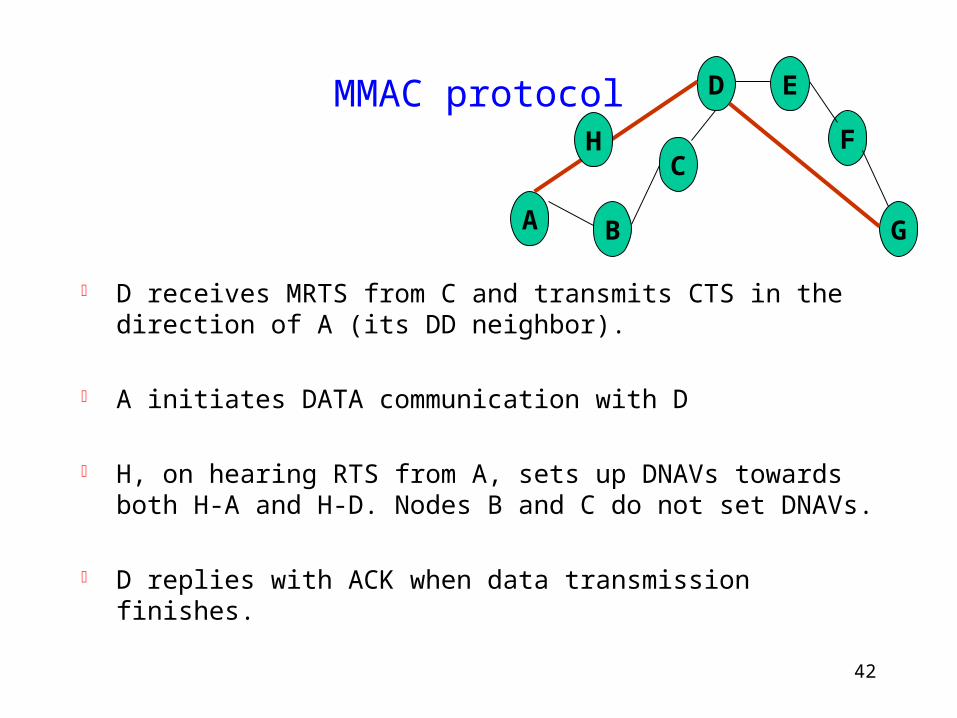
MMAC protocol
D receives MRTS from C and transmits CTS in the direction of A (its DD neighbor).
A initiates DATA communication with D
H, on hearing RTS from A, sets up DNAVs towards both H-A and H-D. Nodes B and C do not set DNAVs.
D replies with ACK when data transmission finishes.
A B
C
D E
F
G
H
43
Performance
Simulation Qualnet simulator 2.6.1 CBR traffic Packet Size – 512 Bytes 802.11 transmission range = 250 meters. Channel bandwidth 2 Mbps Mobility - none
44
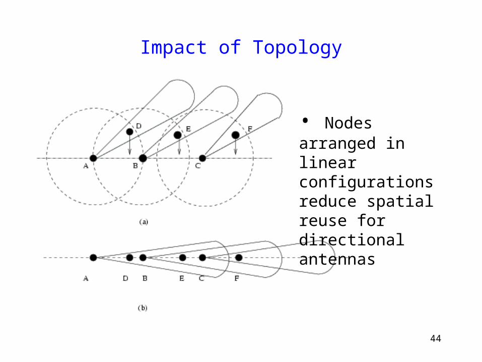
Impact of Topology
• Nodes arranged in linear configurations reduce spatial reuse for directional antennas
45
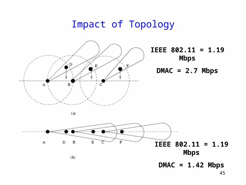
Impact of Topology
IEEE 802.11 = 1.19 Mbps
DMAC = 2.7 Mbps
IEEE 802.11 = 1.19 Mbps
DMAC = 1.42 Mbps
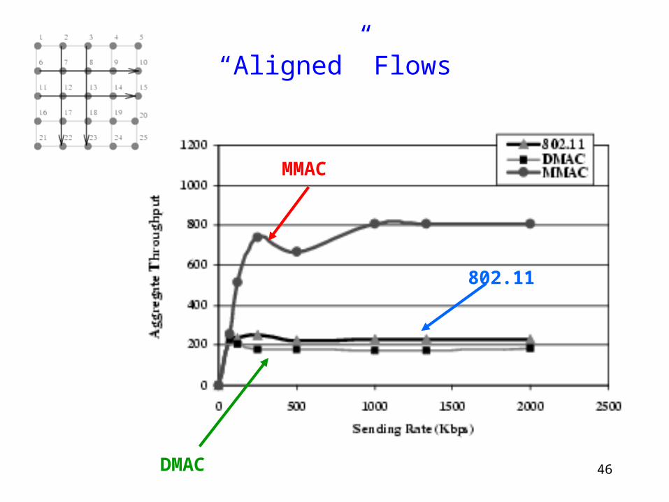
46
“Aligned” Flows
MMAC
DMAC
802.11
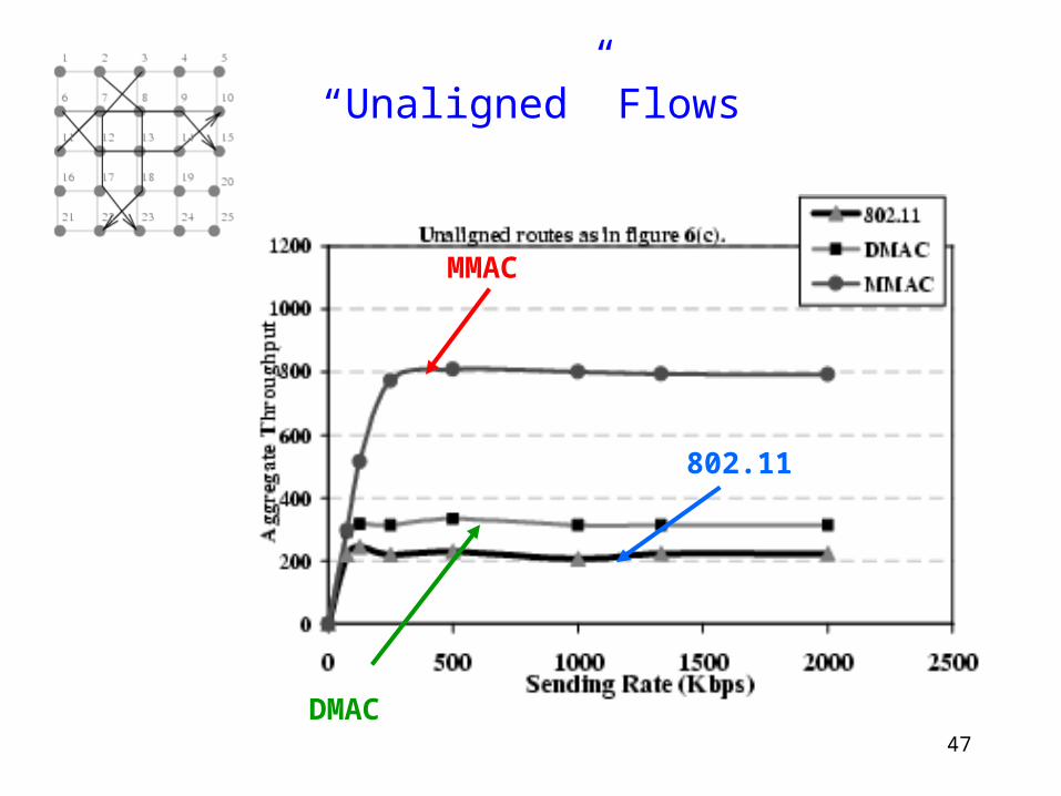
47
“Unaligned” Flows
MMAC
DMAC
802.11
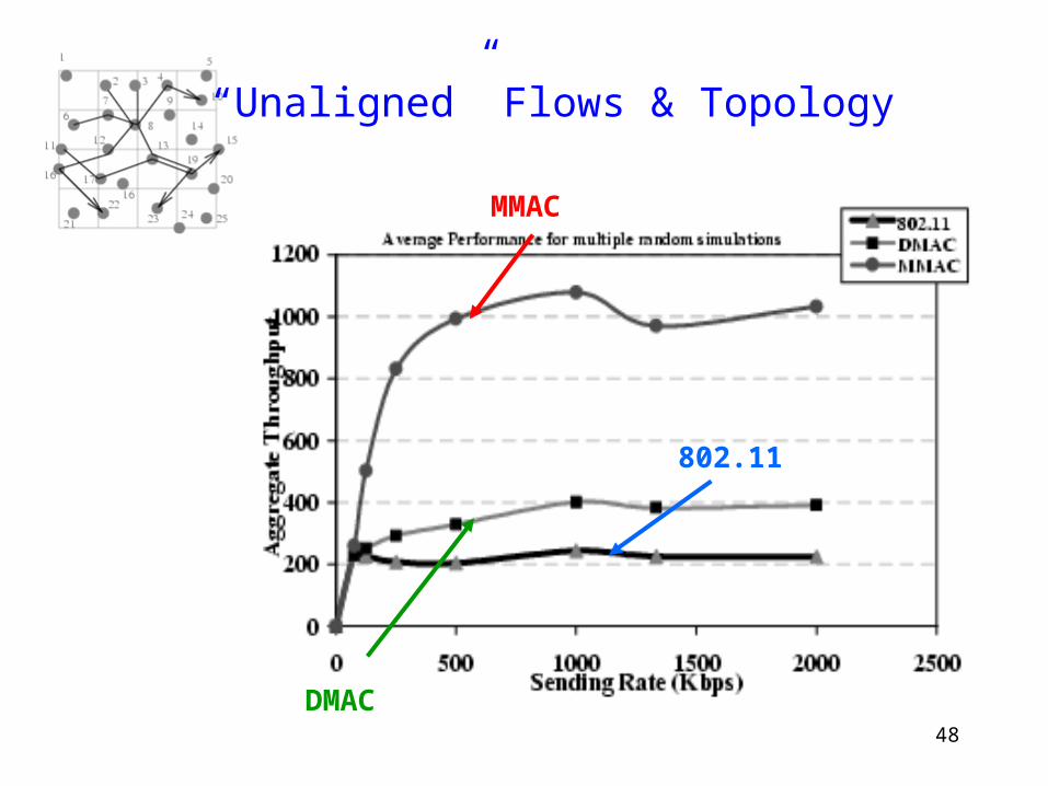
48
“Unaligned” Flows & Topology
MMAC
DMAC
802.11
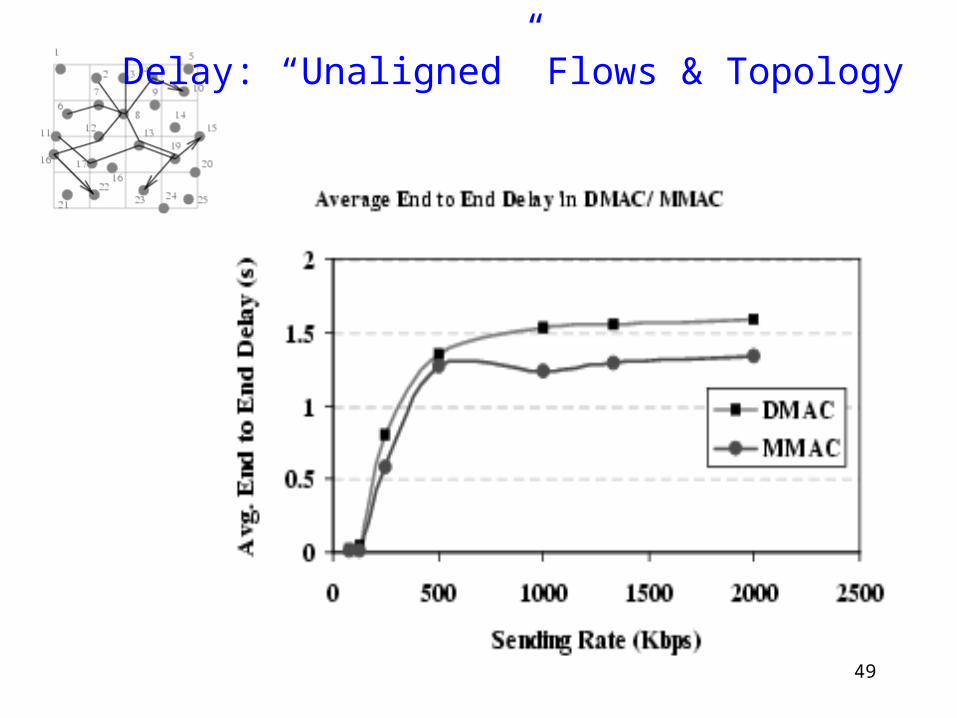
49
Delay: “Unaligned” Flows & Topology
50
Directional MAC: Summary
Directional MAC protocols can improve throughput and decrease delay But not always
Performance dependent on topology
51
Routing using Directional Antennas
52
Motivation
Directional antennas affect network layer, in addition to MAC protocols
53
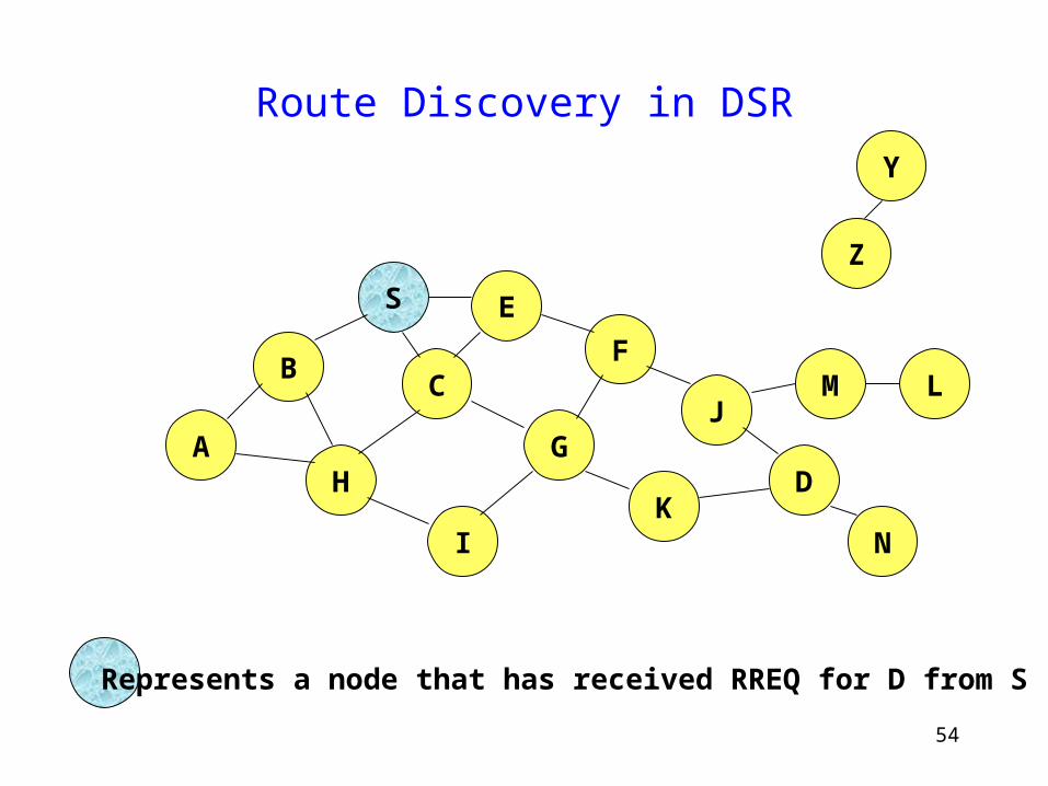
Dynamic Source Routing [Johnson]
Sender floods RREQ through the network
Nodes forward RREQs after appending their names
Destination node receives RREQ and unicasts a RREP back to sender node, using the route in which RREQ traveled
54
Route Discovery in DSR
B
A
S E
F
H
J
D
C
G
IK
Z
Y
Represents a node that has received RREQ for D from S
M
N
L
55
Route Discovery in DSR
B
A
S E
F
H
J
D
C
G
IK
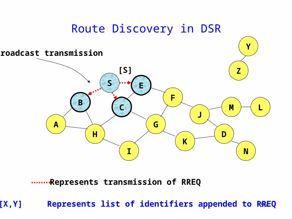
Represents transmission of RREQ
Z
YBroadcast transmission
M
N
L
[S]
[X,Y] Represents list of identifiers appended to RREQ
56
Route Discovery in DSR
B
A
S E
F
H
J
D
C
G
IK
Z
Y
M
N
L
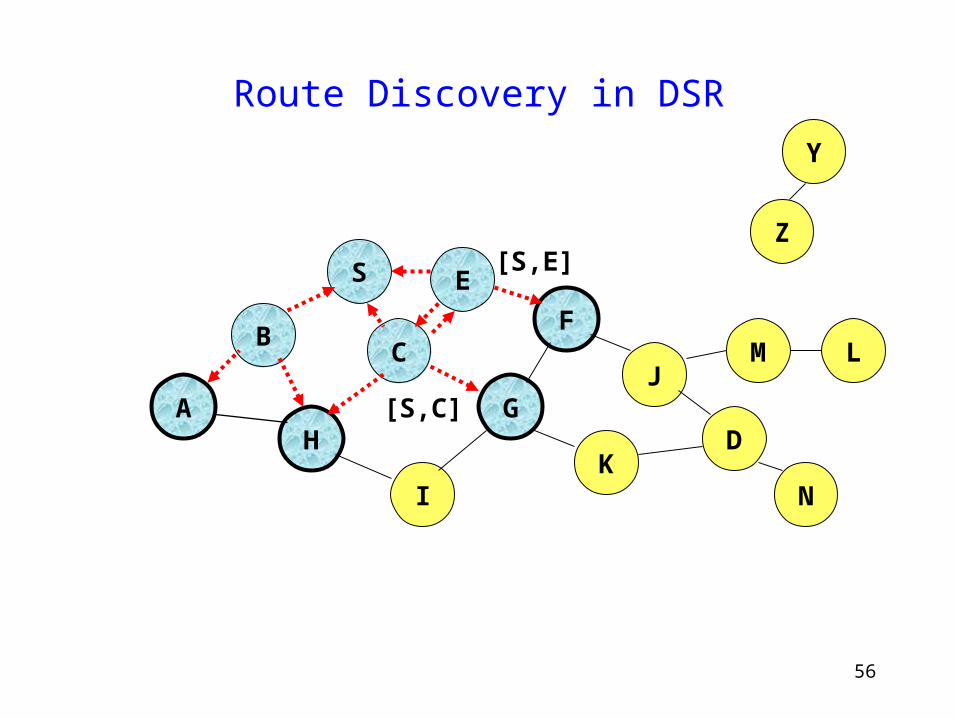
[S,E]
[S,C]
57
Route Discovery in DSR
B
A
S E
F
H
J
D
C
G
IK
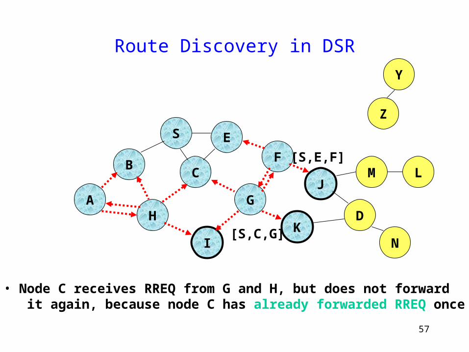
• Node C receives RREQ from G and H, but does not forward it again, because node C has already forwarded RREQ once
Z
Y
M
N
L
[S,C,G]
[S,E,F]
58
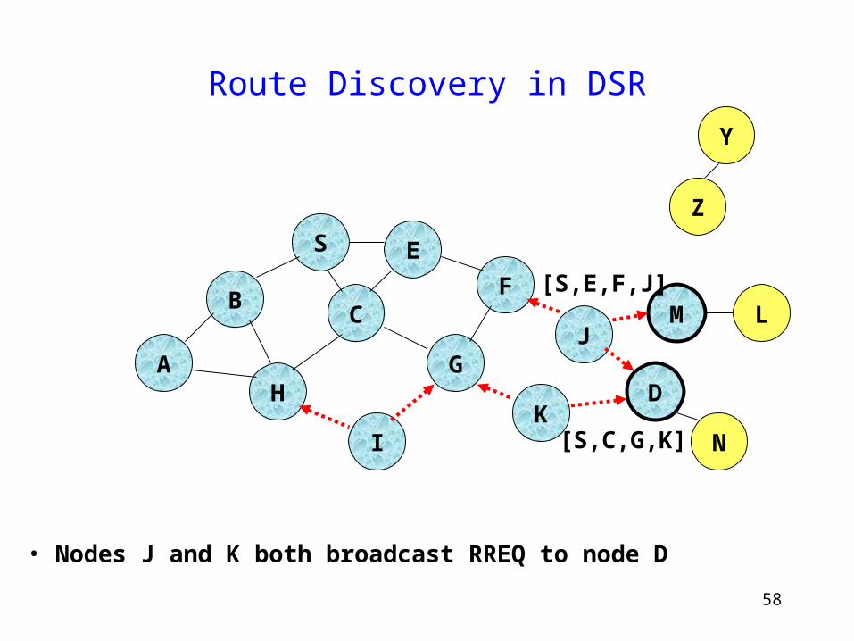
Route Discovery in DSR
B
A
S E
F
H
J
D
C
G
IK
Z
Y
M
• Nodes J and K both broadcast RREQ to node D
N
L
[S,C,G,K]
[S,E,F,J]
59
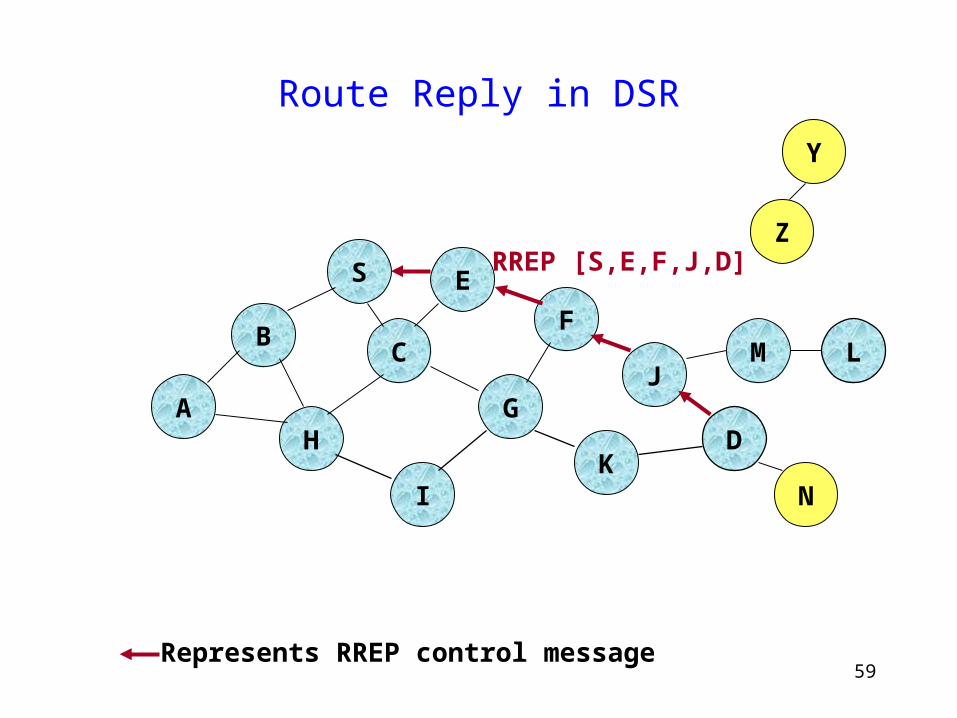
Route Reply in DSR
B
A
S E
F
H
J
D
C
G
IK
Z
Y
M
N
L
RREP [S,E,F,J,D]
Represents RREP control message
60
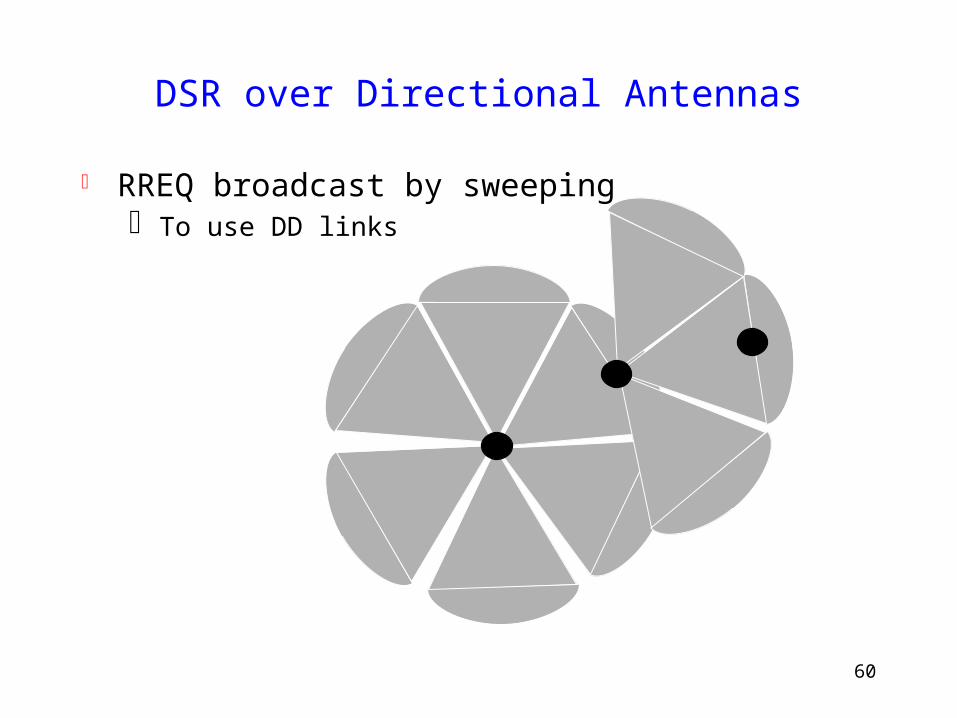
DSR over Directional Antennas
RREQ broadcast by sweeping To use DD links

61
Route Discovery in DSR
B
A
S E
F
H
J
D
C
G
IK
Z
Y
M
• Nodes J and K both broadcast RREQ to node D
N
L
[S,C,G,K]
[S,E,F,J]
62
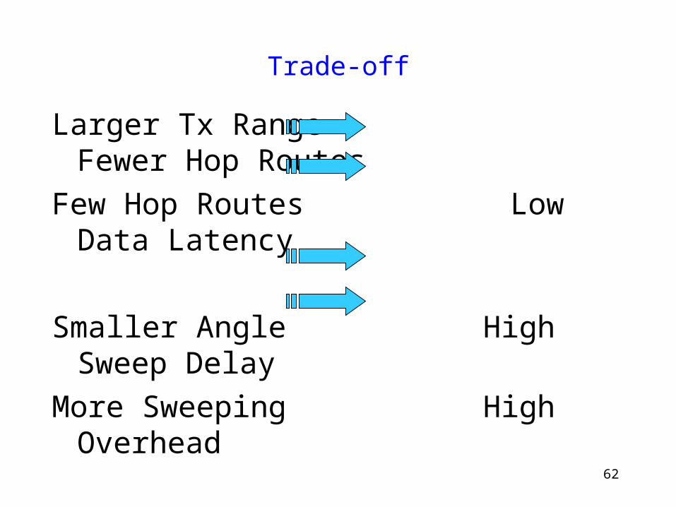
Trade-off
Larger Tx Range Fewer Hop Routes
Few Hop Routes Low Data Latency
Smaller Angle High Sweep Delay
More Sweeping High Overhead
63
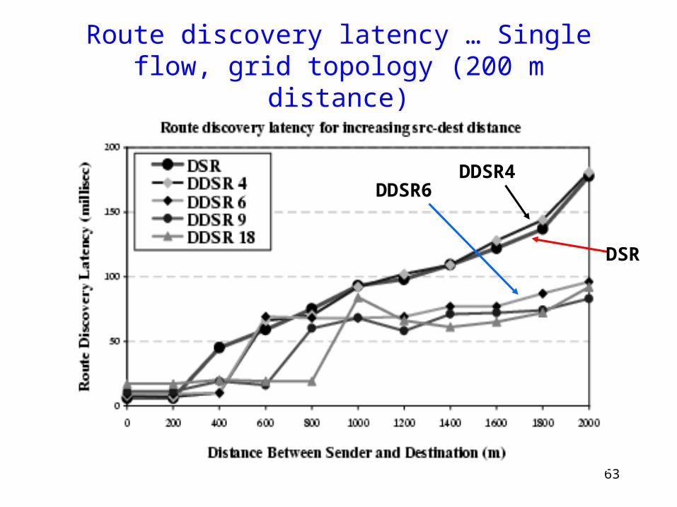
Route discovery latency … Single flow, grid topology (200 m distance)
DSR
DDSR4DDSR6
64
Observations
Advantage of higher transmit range significant only at higher distance of separation.
Grid distance = 200 m --- thus no gain with higher tx range of DDSR4 (350 m) over 802.11 (250 m).
However, DDSR4 has sweeping delay. Thus route discovery delay higher
65
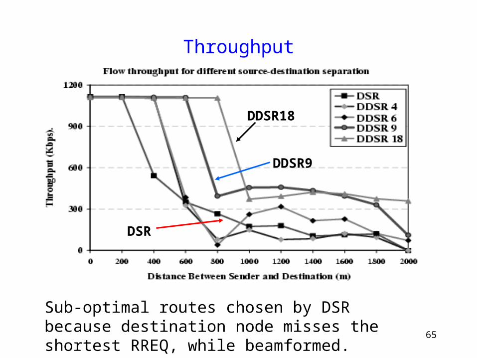
Throughput
Sub-optimal routes chosen by DSR because destination node misses the shortest RREQ, while beamformed.
DDSR18
DDSR9
DSR
66
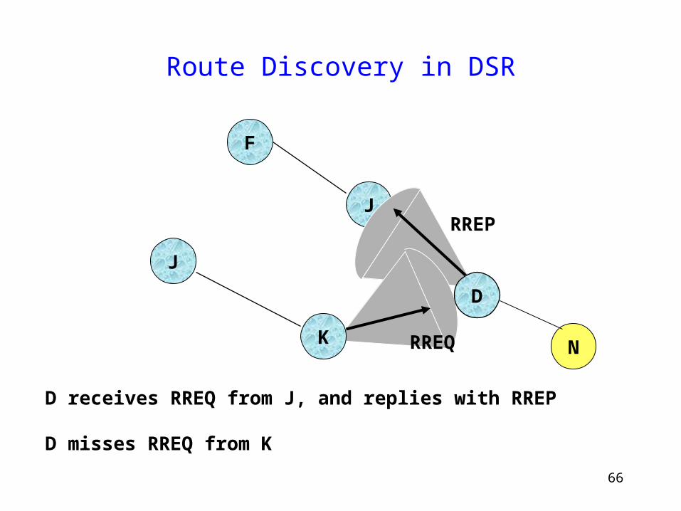
Route Discovery in DSR
F
J
D receives RREQ from J, and replies with RREP
D misses RREQ from K
N
J
RREP
RREQ
D
K
67
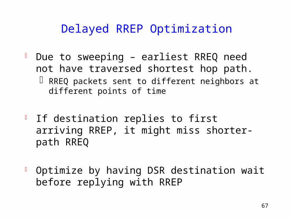
Delayed RREP Optimization
Due to sweeping – earliest RREQ need not have traversed shortest hop path. RREQ packets sent to different neighbors at different points
of time
If destination replies to first arriving RREP, it might miss shorter-path RREQ
Optimize by having DSR destination wait before replying with RREP
68
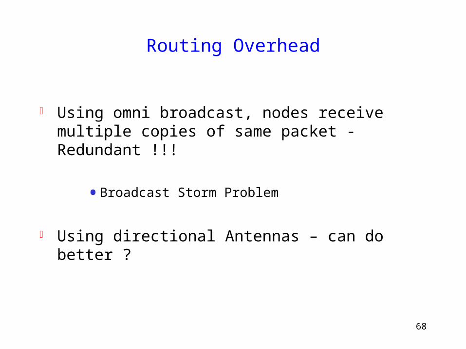
Routing Overhead
Using omni broadcast, nodes receive multiple copies of same packet - Redundant !!!
• Broadcast Storm Problem
Using directional Antennas – can do better ?
69
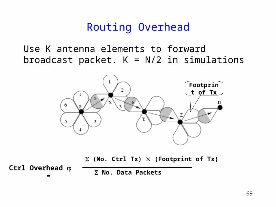
Use K antenna elements to forward broadcast packet. K = N/2 in simulations
Routing Overhead
Footprint of Tx
(No. Ctrl Tx) (Footprint of Tx) No. Data Packets
Ctrl Overhead =
70
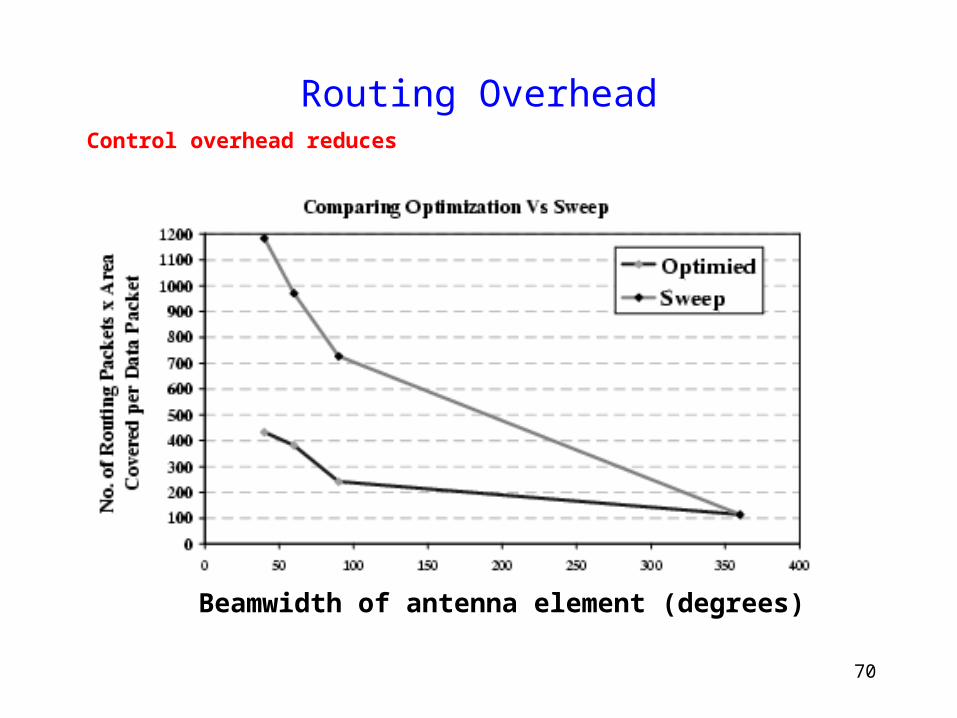
Routing OverheadControl overhead reduces
Beamwidth of antenna element (degrees)
71
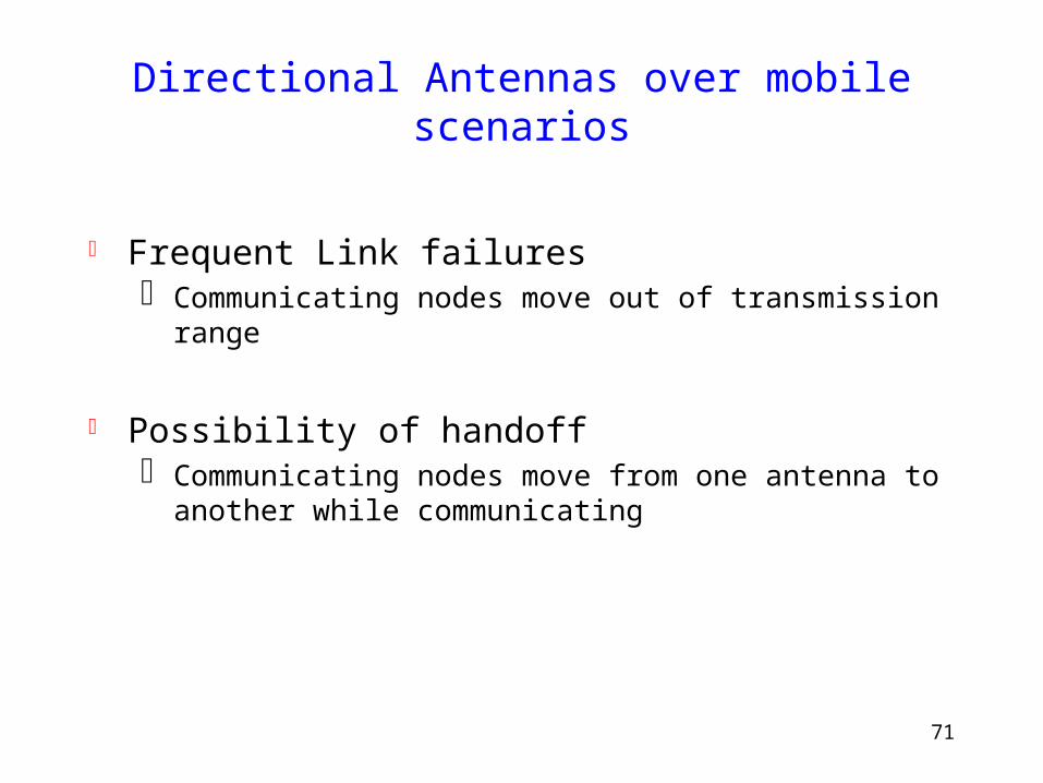
Directional Antennas over mobile scenarios
Frequent Link failures Communicating nodes move out of transmission range
Possibility of handoff Communicating nodes move from one antenna to another
while communicating
72
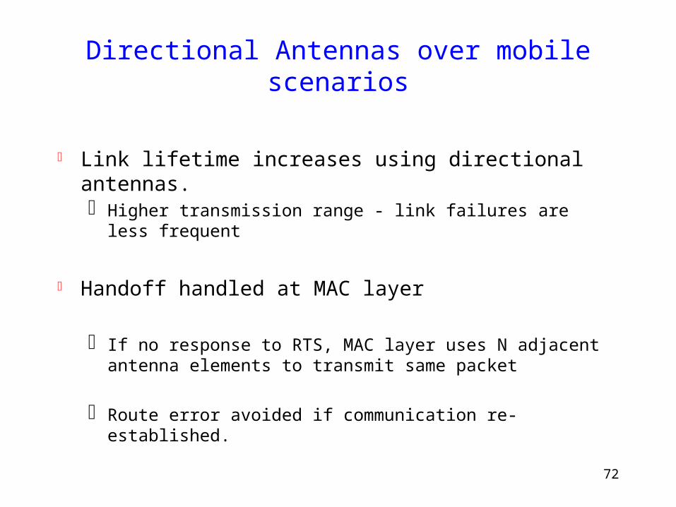
Directional Antennas over mobile scenarios
Link lifetime increases using directional antennas. Higher transmission range - link failures are less frequent
Handoff handled at MAC layer
If no response to RTS, MAC layer uses N adjacent antenna elements to transmit same packet
Route error avoided if communication re-established.
73
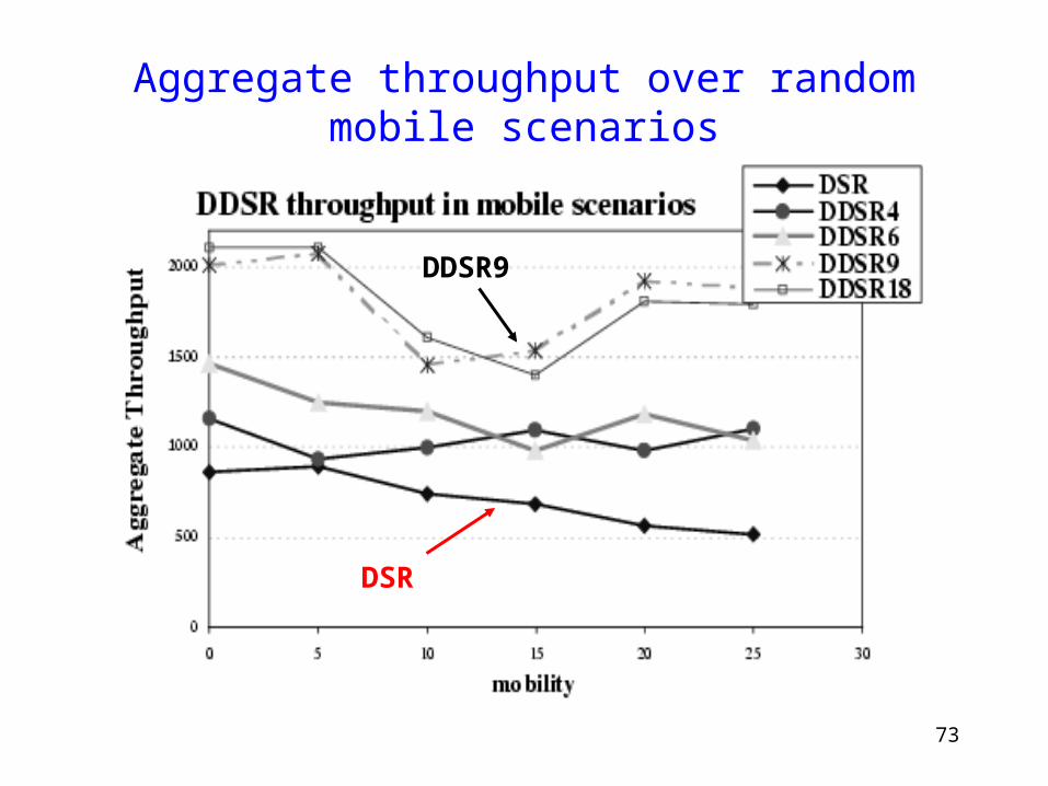
Aggregate throughput over random mobile scenarios
DSR
DDSR9
74
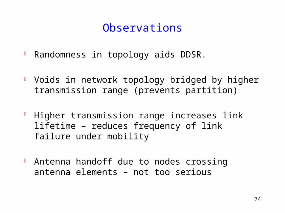
Observations
Randomness in topology aids DDSR.
Voids in network topology bridged by higher transmission range (prevents partition)
Higher transmission range increases link lifetime – reduces frequency of link failure under mobility
Antenna handoff due to nodes crossing antenna elements – not too serious
75
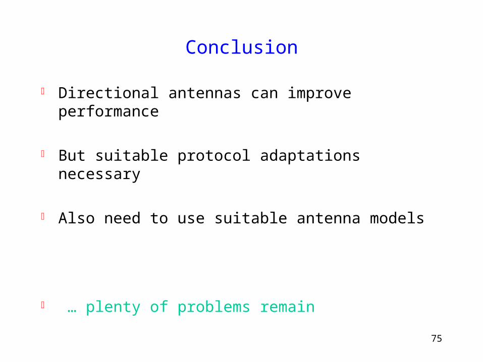
Conclusion
Directional antennas can improve performance
But suitable protocol adaptations necessary
Also need to use suitable antenna models
… plenty of problems remain

76
Thanks!
www.crhc.uiuc.edu/~nhv

77
78
Adaptive Modulation
Joint work with Gavin Holland and Victor Bahl
79
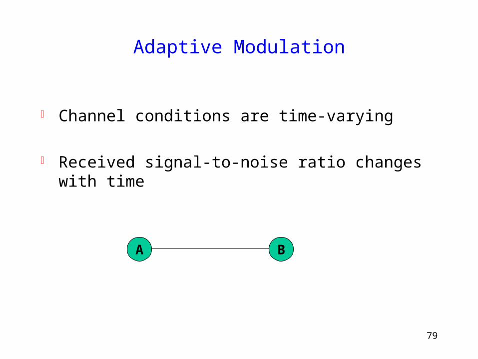
Adaptive Modulation
Channel conditions are time-varying
Received signal-to-noise ratio changes with time
A B
80
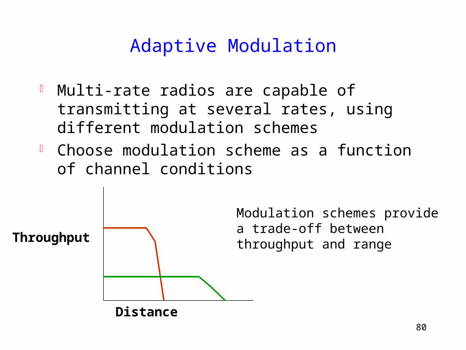
Adaptive Modulation
Multi-rate radios are capable of transmitting at several rates, using different modulation schemes
Choose modulation scheme as a function of channel conditions
Distance
Throughput
Modulation schemes providea trade-off betweenthroughput and range
81
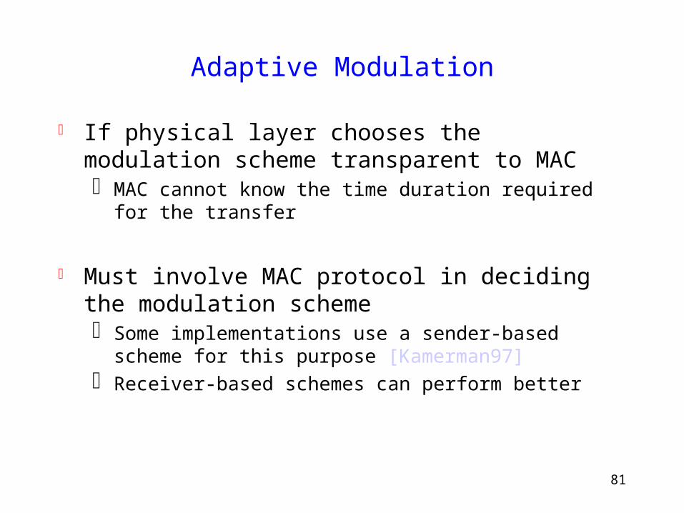
Adaptive Modulation
If physical layer chooses the modulation scheme transparent to MAC MAC cannot know the time duration required for the transfer
Must involve MAC protocol in deciding the modulation scheme Some implementations use a sender-based scheme for this
purpose [Kamerman97] Receiver-based schemes can perform better
82
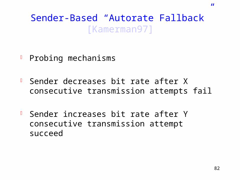
Sender-Based “Autorate Fallback” [Kamerman97]
Probing mechanisms
Sender decreases bit rate after X consecutive transmission attempts fail
Sender increases bit rate after Y consecutive transmission attempt succeed
83
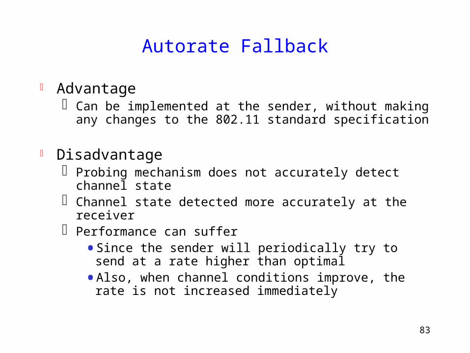
Autorate Fallback
Advantage Can be implemented at the sender, without making any
changes to the 802.11 standard specification
Disadvantage Probing mechanism does not accurately detect channel
state Channel state detected more accurately at the receiver Performance can suffer
• Since the sender will periodically try to send at a rate higher than optimal
• Also, when channel conditions improve, the rate is not increased immediately
84
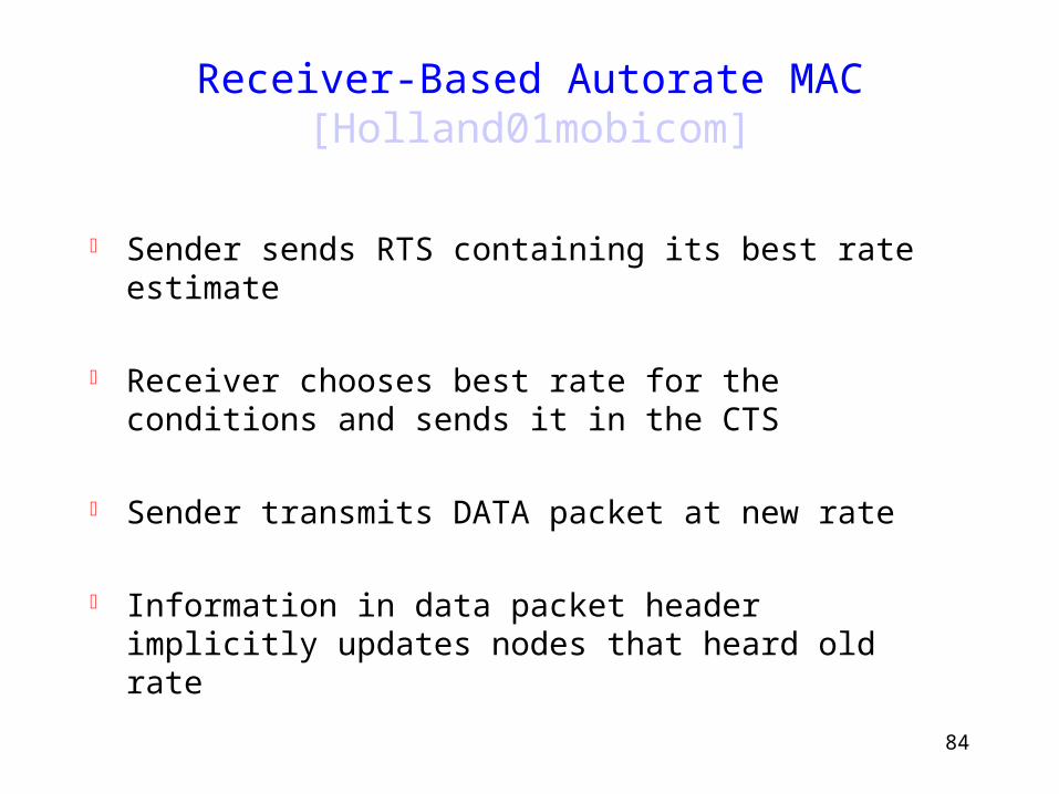
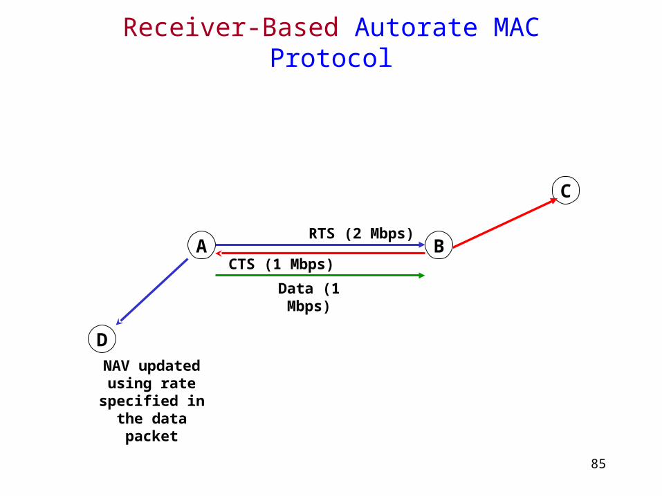
Receiver-Based Autorate MAC [Holland01mobicom]
Sender sends RTS containing its best rate estimate
Receiver chooses best rate for the conditions and sends it in the CTS
Sender transmits DATA packet at new rate
Information in data packet header implicitly updates nodes that heard old rate
85
Receiver-Based Autorate MAC Protocol
D
C
BACTS (1 Mbps)
RTS (2 Mbps)
Data (1 Mbps)
NAV updated using rate
specified in the data packet

86
Extra slides
87
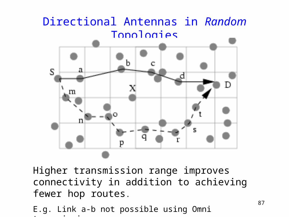
Directional Antennas in Random Topologies
Higher transmission range improves connectivity in addition to achieving fewer hop routes.
E.g. Link a-b not possible using Omni transmission.
88
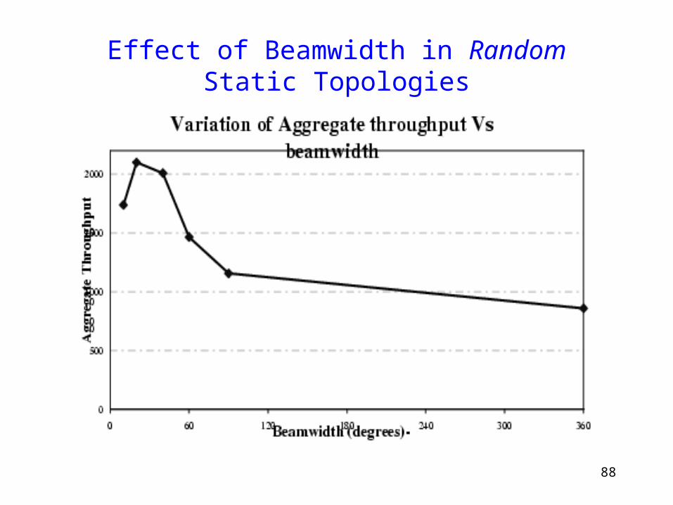
Effect of Beamwidth in Random Static Topologies