1 core instruction170.211.194.2/physics/physics_files/te_ch20.pdfelectromagnetic induction 690a...
TRANSCRIPT
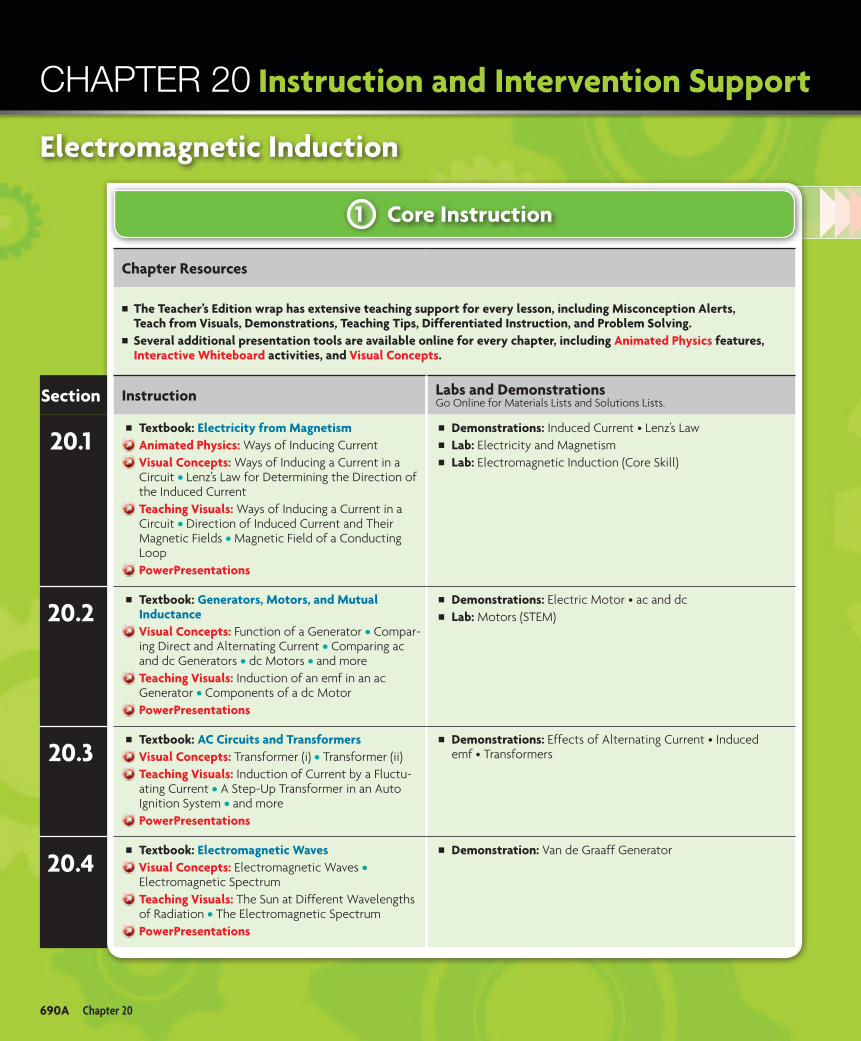
1 Core Instruction
Instruction and Intervention Support
Chapter Resources
The Teacher’s Edition wrap has extensive teaching support for every lesson, including Misconception Alerts,
Teach from Visuals, Demonstrations, Teaching Tips, Differentiated Instruction, and Problem Solving.Several additional presentation tools are available online for every chapter, including Animated Physics features, Interactive Whiteboard activities, and Visual Concepts.
Section Instruction Labs and DemonstrationsGo Online for Materials Lists and Solutions Lists.
20.1Textbook: Electricity from MagnetismAnimated Physics: Ways of Inducing CurrentVisual Concepts: Ways of Inducing a Current in a Circuit • Lenz’s Law for Determining the Direction of the Induced CurrentTeaching Visuals: Ways of Inducing a Current in a Circuit • Direction of Induced Current and Their Magnetic Fields • Magnetic Field of a Conducting LoopPowerPresentations
Demonstrations: Induced Current • Lenz’s LawLab: Electricity and MagnetismLab: Electromagnetic Induction (Core Skill)
20.2 Textbook: Generators, Motors, and Mutual InductanceVisual Concepts: Function of a Generator • Compar-ing Direct and Alternating Current • Comparing ac and dc Generators • dc Motors • and moreTeaching Visuals: Induction of an emf in an ac Generator • Components of a dc MotorPowerPresentations
Demonstrations: Electric Motor • ac and dcLab: Motors (STEM)
20.3Textbook: AC Circuits and TransformersVisual Concepts: Transformer (i) • Transformer (ii)Teaching Visuals: Induction of Current by a Fluctu-ating Current • A Step-Up Transformer in an Auto Ignition System • and morePowerPresentations
Demonstrations: Effects of Alternating Current • Induced emf • Transformers
20.4 Textbook: Electromagnetic Waves Visual Concepts: Electromagnetic Waves • Electromagnetic SpectrumTeaching Visuals: The Sun at Different Wavelengths of Radiation • The Electromagnetic SpectrumPowerPresentations
Demonstration: Van de Graaff Generator
Electromagnetic Induction
690A Chapter 20
CHAPTER 20

Where do I find it?
3 Specialized Support2 Support and Intervention
Find all of your resources online at HMDScience.com.
PRINT DVD ONLINE
Animated Physics
Demonstrations (TE wrap)
Labs
PowerPresentations
QuickLabs
Teaching Visuals
Textbook
Visual Concepts
Interactive Demos
Concept Maps
Sample Problem Set I
Sample Problem Set II
Scientific Reasoning Skill Builder
Study Guide
Chapter Summary Audio Files
Differentiated Instruction (TE wrap)
AssessmentSection Quizzes
Chapter Tests A and B
Alternative Assessment (SE)
Online Assessment and Remediation
ExamView Banks
Enrichment and ChallengeDifferentiated Instruction: Pre-AP (TE wrap)
Why It Matters (STEM): Electric Guitar Pickups (SE)
Why It Matters (STEM): Avoiding Electrocution (SE)
Why It Matters: Radio and TV Broadcasts (SE)
Timeline—Physics and Its World: 1830–1890 (SE)
Chapter Summary Audio Files
Differentiated Instruction: Inclusion and Below Level (TE wrap)
Study Guide
Concept Maps Scientific Reasoning Skill Builder
Interactive DemosSample Problem Set ISample Problem Set II
PREMIUM Content
Electromagnetic Induction 690B

I
I
N NN N NN
S
The vibrations of the strings in an electric guitar change the magnetic field near a coil of wire called the pickup. In turn, this induces an electric current in the coil, which is then amplified to create the unique sound of an electric guitar.
(bg)
©Aa
ron
Jone
s St
udio
/Get
ty Im
ages
690
Untitled-724 690 5/26/2011 9:47:49 AM
Lab Preview
Chapter OverviewSection 1 introduces induced current, discusses Lenz’s law, and applies Faraday’s law of induction to calculate induced emf and induced current.
Section 2 introduces generators and motors—devices that convert energy from one form to another—and examines mutual inductance.
Section 3 shows how to calculate the rms current for ac circuits, discusses transformers, and shows how to calculate the emf for a step-up or step-down transformer.
Section 4 further explores electromag-netic waves and the electromagnetic spectrum, first introduced in the chapter “Light and Reflection.”
About the ImageThe strings of an electric guitar are magnetized by a permanent magnet located inside coils of wire beneath the strings. Two sets of coils—one at the base of the neck and the other just above the bridge—can be seen in each of the guitars in the photograph. As a string vibrates, the changing magnetic field induces in the coil an alternating current, whose frequency depends on the string’s frequency.
The following investigations support the concepts presented in this chapter.
LAbSElectricity and Magnetism
Electromagnetic Induction (Core Skill)
Motors (STEM)
DemOnStrAtIOnSInduced Current
Lenz’s Law
Electric Motor
ac and dc
Effects of Alternating Current
Induced emf
Transformers
Van de Graaff Generator
690 Chapter 20
CHAPTER 20

PhysicsHMDScience.com
PREMIUM CONTENT
ONLINE PhysicsHMDScience.com
(bg)
©Aa
ron
Jone
s St
udio
/Get
ty Im
ages
Ways of Inducing Current
ONLINE LABS Electricity and Magnetism
Electromagnetic Induction
Motors
Why It Matters Electric guitars have many different types of pickups, but all generate electric current by the process of induction. An understanding of the induction of electromag-netic fields is essential to the good design of an electric guitar.
Electromagnetic Electromagnetic InductionInduction
Electromagnetic Induction
Electromagnetic Electromagnetic Induction
Electromagnetic
691
SECTION 1
Electricity from MagnetismSECTION 2
Generators, Motors, and Mutual InductanceSECTION 3
AC Circuits and TransformersSECTION 4
Electromagnetic Waves
CHAPTER 20
Untitled-724 691 5/26/2011 9:47:56 AM
Why It matters
Activate Prior KnowledgeKnOWLeDge tO revIeW•Thedefinitionofresistancestatesthat
the current in a circuit is proportional to the applied potential difference and inversely proportional to the resistance of the circuit.
•Emfproducesanelectricfieldthatcauses a force on free charges in a conductor. This force causes the free charges to move through the conductor. These moving charges are called an electric current.
•Achargedparticlemovingina magnetic field experiences a magnetic force. When the particle moves with a component perpendicular to the field, F
magnetic = qvB.
ItemS tO PrObe•Resistance: Have students calculate
current for various cases involving changing potential differences.
Focus and Motivate
COnneCtIng tO SOCIetyApplications of electromagnetic induction have had a profound effect on society. We have become increasingly dependent on electricity to power everything from life-support machines in hospitals to chargers for electronic devices such as phones. What happens to these items in a power outage?
Many places that carry out essential life functions (such as hospitals and shelters for natural disasters) are equipped with emergency
power generators. These generators generate current by the process of induction. The design of these devices relies on the concept of electromagnetic induction.
After briefly describing the importance of electromagnetic induction to students, point out that generators do not create energy but convert one form of energy into electrical energy. Ask them where the fuel comes from to operate a generator. Do they know of anyone who has a generator? What is its fuel?
Electromagnetic Induction 691

100
200
300
400
500600700
800900
100
200
300
400
500600700
800900
1000
Magnetic eldGalvanometer
NS
0
Current
Key Termelectromagnetic induction
Electromagnetic InductionRecall that when you were studying circuits, you were asked if it was possible to produce an electric current using only wires and no battery. So far, all electric circuits that you have studied have used a battery or an electrical power supply to create a potential difference within a circuit. The electric field associated with that potential difference causes charges to move through the circuit and to create a current.
It is also possible to induce a current in a circuit without the use of a battery or an electrical power supply. You have learned that a current in a circuit is the source of a magnetic field. Conversely, a current results when a closed electric circuit moves with respect to a magnetic field, as shown in Figure 1.1. The process of inducing a current in a circuit by changing the magnetic field that passes through the circuit is called electromagnetic induction.
Consider a closed circuit consisting of only a resistor that is in the vicinity of a magnet. There is no battery to supply a current. If neither the magnet nor the circuit is moving with respect to the other, no current will be present in the circuit. But, if the circuit moves toward or away from the magnet or the magnet moves toward or away from the circuit, a current is induced. As long as there is relative motion between the two, a current is created in the circuit.
The separation of charges by the magnetic force induces an emf.It may seem strange that there can be an induced emf and a correspond-ing induced current without a battery or similar source of electrical
Electricity from Magnetism
Objectives
Recognize that relative motion between a conductor and a magnetic field induces an emf in the conductor.
Describe how the change in the number of magnetic field lines through a circuit loop affects the magnitude and direction of the induced electric current.
Apply Lenz’s law and Faraday’s law of induction to solve problems involving induced emf and current.
electromagnetic induction the process of creating a current in a circuit loop by changing the magnetic flux in the loop
Electromagnetic Induction When the circuit loop crosses the lines of the magnetic field, a current is induced in the circuit, as indicated by the movement of the galvanometer needle.
FIGURE 1.1
Chapter 20692
SECTION 1
Untitled-785 692 6/3/2011 4:12:40 PM
Differentiated Instruction
Preview VocabularyLatin Word Origins The word induction comes from the Latin inductus, meaning “to lead.” Relate the Latin root to the definition of induction by explaining that induction processes “lead” a current through a circuit loop. Electromagnetic induction creates electricity by inducting a current through a circuit loop by changing magnetic flux.
Teaching TipRemind students that as discussed in the chapter on magnetism, electric charges that move through a magnetic field experience a magnetic force. The maximum value of this force is qvB. When charges are at rest with respect to the magnetic field (v = 0 m/s), they do not experience a magnetic force.
FIGURE 1.1 Be sure students understand the conditions required to induce a current in a circuit.
Ask Why is a current generated in a moving conductor in a magnetic field but not in a moving insulator in the same magnetic field?
Answer: A force acts on the charges in both cases. In conductors, the electrons are free to move in response to the magnetic force. A force also acts on the electrons in an insulator, but these electrons are not free to move.
Ask What condition is required for current to exist in the circuit in Fig. 1.1?
Answer: There must be relative motion between the circuit and the magnetic field; when the two are at rest relative to one another, charges in the conducting wires do not experience a magnetic force, so there is no induced current.
Plan and Prepare
Teach
TEACH FROM VISUALS
BELOW LEVELAs a scaffolding for below-level learners, give a review explanation of emf. Tell students that emf is the external work expected per unit of charge to produce an electric potential difference. This difference is created by separating positive and negative charges, which generates an electric field.
692 Chapter 20
SECTION 1

HRW • Holt PhysicsPH99PE-C22-001-004-A
vv v
(a) (b) (c)
B (out of page)
HRW • Holt PhysicsPH99PE-C22-001-002-A
v=
-
+
–+
energy. Recall from that a moving charge can be deflected by a magnetic field. This deflection can be used to explain how an emf occurs in a wire that moves through a magnetic field.
Consider a conducting wire pulled through a magnetic field, as shown on the left in Figure 1.2. You learned when studying magnetism that charged particles moving with a velocity at an angle to the magnetic field will experience a magnetic force. According to the right-hand rule, this force will be perpendicular to both the magnetic field and the motion of the charges. For free positive charges in the wire, the force is directed downward along the wire. For negative charges, the force is upward. This effect is equivalent to replacing the segment of wire and the magnetic field with a battery that has a potential difference, or emf, between its terminals, as shown on the right in Figure 1.2. As long as the conducting wire moves through the magnetic field, the emf will be maintained.
The polarity of the induced emf depends on the direction in which the wire is moved through the magnetic field. For instance, if the wire in Figure 1.2 is moved to the right, the right-hand rule predicts that the negative charges will be pushed upward. If the wire is moved to the left, the negative charges will be pushed downward. The magnitude of the induced emf depends on the velocity with which the wire is moving through the magnetic field, on the length of the wire in the field, and on the strength of the magnetic field.
The angle between a magnetic field and a circuit affects induction.One way to induce an emf in a closed loop of wire is to move all or part of the loop into or out of a constant magnetic field. No emf is induced if the loop is static and the magnetic field is constant.
The magnitude of the induced emf and current depend partly on how the loop is oriented to the magnetic field, as shown in Figure 1.3. The induced current is largest if the plane of the loop is perpendicular to the magnetic field, as in (a); it is smaller if the plane is tilted into the field, as in (b); and it is zero if the plane is parallel to the field, as in (c).
The role that the orientation of the loop plays in inducing the current can be explained by the force that the magnetic field exerts on the charges in the moving loop. Only the component of the magnetic field perpendicular to
Orientation of a Loop in a Magnetic Field These three loops of wire are moving out of a region that has a constant magnetic field. The induced emf and current are largest when the plane of the loop is perpendicular to the magnetic field (a), smaller when the plane of the loop is tilted (b), and zero when the plane of the loop and the magnetic field are parallel (c).
FIGURE 1.3
Potential Difference in a Wire The separation of positive and negative moving charges by the magnetic force creates a potential difference (emf) between the ends of the conductor.
FIGURE 1.2
Electromagnetic Induction 693
Untitled-785 693 6/3/2011 4:12:41 PM
FIGURE 1.3 Point out that any charge with a velocity component perpendicular to a magnetic field will experience a force that is perpendicular both to the magnetic field and to that velocity component.
Ask Why does a loop that is parallel to the field and moves as shown in Figure 1.3(c) experience no current around the loop, even though the loop is moving in the magnetic field?
Answer: The electrons do experience a magnetic force perpendicular to the field, but they cannot move in that direction because the loop is parallel to the field.
TEACH FROM VISUALS
BELOW LEVELRemind students that, as seen in the chapter on magnetism, a current creates a mag netic field whose direction can be found with the right-hand rule. If the thumb points in the direction of conventional current (moving positive charges), the right hand wraps around the wire in the direction of the magnetic field.
Electromagnetic Induction 693

both the plane and the motion of the loop exerts a magnetic force on the charges in the loop. If the area of the loop is moved parallel to the magnetic field, there is no magnetic field component perpendicular to the plane of the loop and therefore no induced emf to move the charges around the circuit.
Change in the number of magnetic field lines induces a current.So far, you have learned that moving a circuit loop into or out of a mag-netic field can induce an emf and a current in the circuit. Changing the size of the loop or the strength of the magnetic field also will induce an emf in the circuit.
One way to predict whether a current will be induced in a given situation is to consider how many magnetic field lines cut through the loop. For example, moving the circuit into the magnetic field causes some lines to move into the loop. Changing the size of the circuit loop or rotating the loop changes the number of field lines passing through the loop, as does changing the magnetic field’s strength or direction. Figure 1.4 summarizes these three ways of inducing a current.
Characteristics of Induced CurrentSuppose a bar magnet is pushed into a coil of wire. As the magnet moves into the coil, the strength of the magnetic field within the coil increases, and a current is induced in the circuit. This induced current in turn produces its own magnetic field, whose direction can be found by using the right-hand rule. If you were to apply this rule for several cases, you would notice that the induced magnetic field direction depends on the change in the applied field.
Did YOU Know?
In 1996, the space shuttle Columbia attempted to use a 20.7 km conducting tether to study Earth’s magnetic field in space. The plan was to drag the tether through the magnetic field, inducing an emf in the tether. The magnitude of the emf would directly vary with the strength of the magnetic field. Unfortunately, the tether broke before it was fully extended, so the experiment was abandoned.
FIGURE 1.4
WAYS OF INDUCING A CURRENT IN A CIRCUIT
Description Before After
Circuit is moved into or out of magnetic field (either circuit or magnet moving).
Circuit is rotated in the magnetic field (angle between area of circuit and magnetic field changes).
Intensity and/or direction of magnetic field is varied.
HRW • Holt PhysicsPH99PE-C22-001-005-A
v
B
v
I
HRW • Holt PhysicsPH99PE-C22-001-006-A
IB B
HRW • Holt PhysicsPH99PE-C22-001-007-A
B BI
HRW • Holt PhysicsPH99PE-C22-001-005-A
v
B
v
I
HRW • Holt PhysicsPH99PE-C22-001-006-A
IB B
HRW • Holt PhysicsPH99PE-C22-001-007-A
B BI
Chapter 20694
Untitled-785 694 6/3/2011 4:12:42 PM
Problem Solving
INDUCED CURRENTPurpose Show students an example of an induced current.
Materials flashlight bulb in holder, coil of wire, bar magnet (two may be required), con necting wires
Procedure Connect the flashlight bulb to the coil of wire with the connecting wires. Tell students to observe the demonstration with the intent of explaining the en ergy conversions. Move the bar magnet into and out of the coil several times in rapid succession. Have students explain the energy conversions on the board or in their notebooks. The following energy conversions should be discussed: kinetic energy is converted to electrical energy (moving magnet generates a current) and electrical energy is converted to light (the current heats the light bulb’s filament).
Teach continued
Demonstration
REALITy ChECkA current is induced in a loop when the magnetic flux changes inside a loop. The current produces a magnetic field that opposes the flux change. For example, if the flux decreases, the induced current will produce a magnetic field that increases the flux again. Students can use this fact and the right-hand rule to check their current directions in induction problems.
694 Chapter 20

HRW • Holt PhysicsPH99PE-C22-001-009-A
Recedingmagnetic field
Magnetic field frominduced currentInduced current
Wire
v
N SSN
HRW • Holt PhysicsPH99PE-C22-001-008-A
Approachingmagnetic field
Magnetic field frominduced currentInduced current
Wire
NS
v
N S
Conceptual Challenge
As the magnet approaches, the magnetic field passing through the coil increases in strength. The induced current in the coil is in a direction that produces a magnetic field that opposes the increasing strength of the approaching field. So, the induced magnetic field is in the opposite direction of the increasing magnetic field.
The induced magnetic field is similar to the field of a bar magnet that is oriented as shown in Figure 1.5. The coil and the approaching magnet create a pair of forces that repel each other.
If the magnet is moved away from the coil, the magnetic field passing through the coil decreases in strength. Again, the current induced in the coil produces a magnetic field that opposes the decreasing strength of the receding field. This means that the magnetic field that the coil sets up is in the same direction as the receding magnetic field.
The induced magnetic field is similar to the field of a bar magnet oriented as shown in Figure 1.6. In this case the coil and magnet attract each other.
Magnet Moving Away from Coil When a bar magnet is moved away from a coil, the induced magnetic field is similar to the field of a bar magnet with the orientation shown.
FIGURE 1.6
Magnet Moving Toward Coil When a bar magnet is moved toward a coil, the induced magnetic field is similar to the field of a bar magnet with the orientation shown.
FIGURE 1.5
Falling Magnet A bar magnet is dropped toward the floor, on which lies a large ring of conducting metal. The magnet’s length—and thus the poles of the magnet—is parallel to the direction of motion. Disregarding air resistance, does the magnet fall toward the ring with the constant accel-eration of a freely falling body? Explain your answer.
Induction in a Bracelet Suppose you are wearing a bracelet that is an unbroken ring of copper. If you walk briskly into a strong magnetic field while wearing the bracelet, how would you hold your wrist with respect to the magnetic field in order to avoid inducing a current in the bracelet?
Electromagnetic Induction 695
Untitled-785 695 6/3/2011 4:12:43 PM
Differentiated Instruction
The Language of PhysicsThe term emf originally stood for electromotive force. Today, emf is considered to be analogous to a potential difference instead of a force. Specifically, emf makes charges in a circuit move, just as a potential difference does. To avoid misconceptions, the term electromotive force is not used in this text.
Misconception Alert!Some students may not distinguish between the external mag netic field that induces a current and the magnetic field that is set up by the induced current. Use the two examples discussed on this page to clarify the difference between these two magnetic fields.
AnswersConceptual Challenge 1. no; The magnet’s acceleration is
slightly smaller. The magnet induces a current in the conducting ring, and the magnetic field of this current opposes the field of the falling magnet. This induced field exerts an upward force on the magnet, reducing the magnet’s net acceleration downward.
2. Upon entering and leaving the field, the plane of the bracelet must be parallel to the direction of the field.
INCLUSIONTactile and visual learners may benefit from the construction (or demonstration) of a solenoid having a large number of closely wound turns of insulated copper wire. Connecting ends to the terminal of a galvanometer and bringing the coil swiftly to one pole of the magnet will allow the students to observe the deflections. Keep the coil at rest and bring one end of the magnet swiftly to the coil, and then take it back at the
same speed. This will allow the students to see that the needle deflects to opposite directions and suddenly comes back to the initial position.
Electromagnetic Induction 695

HRW • Holt PhysicsPH99PE-C22-001-010-A
B
Normal toplane of loop
Loop
cos B
The rule for finding the direction of the induced current is called Lenz’s law and is expressed as follows:
The magnetic field of the induced current is in a direction to produce a field that opposes the change causing it.
Note that the field of the induced current does not oppose the applied field but rather the change in the applied field. If the applied field changes, the induced field tends to keep the total field strength constant.
Faraday’s law of induction predicts the magnitude of the induced emf.
Lenz’s law allows you to determine the direction of an induced current in a circuit. Lenz’s law does not provide information on the magnitude of the induced current or the induced emf. To calculate the magnitude of the induced emf, you must use Faraday’s law of magnetic induction. For a single loop of a circuit, this may be expressed as follows:
emf = − ∆ΦM _
∆t
Recall from the chapter on magnetism that the magnetic flux, ΦM, can be written as AB cos θ. This equation means that a change with time of any of the three variables—applied magnetic field strength, B; circuit area, A; or angle of orientation, θ—can give rise to an induced emf. The term B cos θ represents the component of the magnetic field perpen-dicular to the plane of the loop. The angle θ is measured between the applied magnetic field and the normal to the plane of the loop, as indicated in Figure 1.7.
The minus sign in front of the equation is included to indicate the polarity of the induced emf. The sign indicates that the induced magnetic field opposes the change in the applied magnetic field as stated by Lenz’s law.
If a circuit contains a number, N, of tightly wound loops, the average induced emf is simply N times the induced emf for a single loop. The equation thus takes the general form of Faraday’s law of magnetic induction.
Faraday’s Law of Magnetic Induction
emf = −N ∆ΦM _
∆t
average induced emf = −the number of loops in the circuit × the time rate of change of the magnetic flux
In this chapter, N is always assumed to be a whole number.
Recall that the SI unit for magnetic field strength is the tesla (T), which equals one newton per ampere-meter, or N/(A•m). The tesla can also be expressed in the equivalent units of one volt-second per meter squared, or (V•s)/m2. Thus, the unit for emf, as for electric potential, is the volt.
Magnetic Field of a Conducting Loop at an Angle The angle θ is defined as the angle between the magnetic field and the normal to the plane of the loop. B cos θ equals the strength of the magnetic field perpendicular to the plane of the loop.
FIGURE 1.7
Chapter 20696
Untitled-785 696 6/3/2011 4:12:43 PM
Differentiated Instruction
LENz’S LAWPurpose Illustrate Lenz’s law experimentally.
Materials flashlight bulb in holder, coil of wire, diode, connecting wires, bar magnet (or two)
Procedure Repeat the first demonstra-tion, but include a diode in the circuit. Tell students that the diode allows charges to move in only one direction.
Explain to students that you will be testing Lenz’s law experimentally. Point out that inserting the magnet one way (with the north pole first) will generate a current in one direction. Reversing the magnet will generate a current in the opposite direction, which the diode will stop. The light bulb will serve as an indication of the direction of current. Thus, the bulb should light up in one case but not in the other (because the diode blocks current in one direction). Perform the demonstration and verify these conclusions.
Teach continued
Demonstration
INCLUSIONVisual learners may benefit from a concrete example of Lenz’s Law and Faraday’s Law. One instance that illustrates these laws is a discussion of how currents inside strong magnets can create counter-rotating currents in copper or aluminum pipe. The speed of descent of the magnet is slower when dropped inside the pipe than when dropped outside of it. This can be diagrammed or demonstrated for students whose understanding is dependent upon visuals.
696 Chapter 20

Induced emf and Current
Sample Problem A A coil with 25 turns of wire is wrapped around a hollow tube with an area of 1.8 m2. Each turn has the same area as the tube. A uniform magnetic field is applied at a right angle to the plane of the coil. If the field increases uniformly from 0.00 T to 0.55 T in 0.85 s, find the magnitude of the induced emf in the coil. If the resistance in the coil is 2.5 Ω, find the magnitude of the induced current in the coil.
ANALYZE Given: ∆t = 0.85 s A = 1.8 m2 θ = 0.0° N = 25 turns
Bi = 0.00 T = 0.00 V•s/m2
Bf = 0.55 T = 0.55 V•s/m2
R = 2.5 Ω
Unknown: emf = ? I = ?
Diagram: Show the coil before and after the change in the magnetic field.
PLAN Choose an equation or situation: Use Faraday’s law of magnetic induction to find the induced emf in the coil.
emf = −N ∆ΦM _
∆t = −N
∆[AB cos θ] __
∆t
Substitute the induced emf into the definition of resistance to deter-mine the induced current in the coil.
I = emf _ R
Rearrange the equation to isolate the unknown: In this example, only the magnetic field strength changes with time. The other compo-nents (the coil area and the angle between the magnetic field and the coil) remain constant.
emf = -NA cos θ ∆B _ ∆t
Continued
HRW • Holt PhysicsPH99PE-C22-001-011-A
B = 0.00 T at t = 0.00 s
R = 2.5 Ω R = 2.5 Ω
A = 1.8 m2
N = 25 turns
A = 1.8 m2
N = 25 turns
B = 0.55 T at t = 0.85 s
PREMIUM CONTENT
Interactive DemoHMDScience.com
Electromagnetic Induction 697
Untitled-785 697 6/3/2011 4:12:44 PM
Problem Solving
The Language of PhysicsBoth emf and potential difference have similar current driving abilities, and both are measurable in the same units (volts). In terms of emf, Ohm’s law takes the following form:
I = emf _ R
This form of the definition of resistance is used in Sample Problem A.
Classroom PracticeINDUCED EMF AND CURRENTA coil with 25 turns of wire is moving in a uniform magnetic field of 1.5 T. The magnetic field is perpendicular to the plane of the coil. The coil has a cross-sectional area of 0.80 m2. The coil exits the field in 1.0 s.
a. Find the induced emf.
b. Determine the induced current if the coil’s resistance is 1.5 Ω.
Answers: a. a. 3.0 × 101 V b. 2.0 × 101 A
Teaching TipPoint out to students that Lenz’s law is used in the fourth step of Sample Problem A to find the direction of the induced current.
DECONSTRUCTING PROBLEMSSometimes information needed to solve a problem is not given directly, but rather is implied. For problems involving emf and current, students will use the Faraday’s Law equation:
Rather than expressly stating ∆t or A (area), students may be given information needed to determine these on their own, for example, t
i
and tf or r (radius). Students may also need to
use area formulas for basic shapes.
Electromagnetic Induction 697

(tr) ©
SW P
rodu
ctio
ns/P
hoto
disc
/Get
ty Im
ages
Induced emf and Current (continued)
SOLVE Substitute the values into the equation and solve:
emf = −(25)(1.8 m2)(cos 0.0°) ( (0.55 − 0.00) V•s _
m2 __
(0.85 s) ) = −29 V
I = −29 V _ 2.5 Ω
= −12 A
emf = −29 V
I = −12 A
CHECK YOUR WORK
The induced emf, and therefore the induced current, is directed through the coil so that the magnetic field produced by the induced current opposes the change in the applied magnetic field. For the diagram shown on the previous page, the induced magnetic field is directed to the right and the current that produces it is directed from left to right through the resistor.
1. A single circular loop with a radius of 22 cm is placed in a uniform external magnetic field with a strength of 0.50 T so that the plane of the coil is perpendicular to the field. The coil is pulled steadily out of the field in 0.25 s. Find the average induced emf during this interval.
2. A coil with 205 turns of wire, a total resistance of 23 Ω, and a cross-sectional area of 0.25 m2 is positioned with its plane perpendicular to the field of a powerful electromagnet. What average current is induced in the coil during the 0.25 s that the magnetic field drops from 1.6 T to 0.0 T?
3. A circular wire loop with a radius of 0.33 m is located in an external magnetic field of strength +0.35 T that is perpendicular to the plane of the loop. The field strength changes to −0.25 T in 1.5 s. (The plus and minus signs for a magnetic field refer to opposite directions through the coil.) Find the magnitude of the average induced emf during this interval.
4. A 505-turn circular-loop coil with a diameter of 15.5 cm is initially aligned so that its plane is perpendicular to Earth’s magnetic field. In 2.77 ms the coil is rotated 90.0° so that its plane is parallel to Earth’s magnetic field. If an average emf of 0.166 V is induced in the coil, what is the value of Earth’s magnetic field?
Tips and TricksBecause the minimum number of significant figures for the data is two, the calculator answer, 29.11764706, should be rounded to two digits.
Chapter 20698
Untitled-785 698 6/3/2011 4:12:45 PM
Problem Solving
PROBLEM GUIDE AUse this guide to assign problems.
SE = Student Edition Textbook
PW = Sample Problem Set I (online)
PB = Sample Problem Set II (online)
Solving for:
emf SE Sample, 1, 3; Ch. Rvw. 10, 12, 42
PW 4
PB 4–6
I SE Sample, 2; Ch. Rvw. 11
PW 7–8
∆t SE Ch. Rvw. 37
PW Sample, 1–3
PB 9–10
B SE 4; Ch. Rvw. 39
PB Sample, 1–3
N SE Ch. Rvw. 38
PW 5
A PW 6
*Challenging Problem
AnswersPractice A 1. 0.30 V
2. 14 A
3. 0.14 V
4. 4.83 × 10⁻⁵ T
Teach continued
DECONSTRUCTING PROBLEMSIn Practice Problem 1, area is not explicitly provided. The problem mentions radius, r, which can be used to determine area. The equation A = πr2 must be used.
Students must read problems closely to be sure they are using correct values. Using r instead of A would result in an incorrect answer.
698 Chapter 20

HRW • Holt PhysicsPH99PE-C22-001-014-A
R
v
v(a)
(b)
S N
Reviewing Main Ideas
1. A circular current loop made of flexible wire is located in a magnetic field. Describe three ways an emf can be induced in the loop.
2. A bar magnet is positioned near a coil of wire, as shown to the right. What is the direction of the current in the resistor when the magnet is moved to the left, as in (a)? to the right, as in (b)?
3. A 256-turn coil with a cross-sectional area of 0.0025 m2 is placed in a uniform external magnetic field of strength 0.25 T so that the plane of the coil is perpendicular to the field. The coil is pulled steadily out of the field in 0.75 s. Find the average induced emf during this interval.
Critical Thinking
4. Electric guitar strings are made of ferromag netic materials that can be magnetized. The strings lie closely over and perpendicular to a coil of wire. Inside the coil are permanent magnets that magnetize the segments of the strings overhead. Using this arrangement, explain how the vibrations of a plucked string produce an electrical signal at the same frequency as the vibration of the string.
(tr) ©
SW P
rodu
ctio
ns/P
hoto
disc
/Get
ty Im
ages
T he word pickup refers to a device that “picks up” the sound of an instrument and turns the sound into an electrical signal. The most common type of
electric guitar pickup uses electromagnetic induction to convert string vibrations into electrical energy.
In their most basic form, magnetic pickups consist simply of a permanent magnet and a coil of copper wire. A pole piece under each guitar string concentrates and
shapes the magnetic field. Because guitar strings are made from magnetic materials (steel and/or nickel), a vibrating guitar string causes a change in the magnetic field above the pickup. This changing magnetic field induces a current in the pickup coil.
Many turns of very fine gauge wire—finer than the hair on your head—are wound around each pole piece. The number of turns determines the current that the pickup produces, with more windings resulting in a larger current.
Electric Guitar Pickups
Vibrating string
Strings
Wire coil
Magnets
Electrical signal to amplifier
sp08se_magwim28ba 1st Pass vernnbt 6.22.06
Electromagnetic Induction 699
SECTION 1 FORMATIVE ASSESSMENT
Untitled-785 699 6/3/2011 4:12:47 PM
Answers to Section Assessment
Why It MattersELECTRIC GUITAR PICkUPSThe Rickenbacker Company made the first magnetic electric-guitar pickup in 1931. This first magnetic pickup consisted of two U-shaped magnets, pole pieces, and a single coil of wire.
A simple bobbin of wire around a magnet will create a pickup, but will also act as an antenna and pick up stray electrical noise like the 60 Hz hum from ac electricity. In 1956, Seth Lover designed the humbucking pickup to cancel out stray electrical noise. The humbucking pickup has two coils that are wired such that any noise that the coils detect is cancelled and any signal created by magnetic induction (from the string vibrations) is accepted.
Assess Use the Formative Assessment on this page to evaluate student mastery of the section.
Reteach For students who need additional instruction, download the Section Study Guide.
Response to Intervention To reassess students’ mastery, use the Section Quiz, available to print or to take directly online at hMDScience.com.
Assess and Reteach
1. Answers should include any three of the following: moving the loop into or out of the magnetic field; rotating the loop within the magnetic field; changing the strength of the magnetic field through the static loop; altering the loop’s shape.
2. from left to right; from right to left
3. 0.21 V
4. When the magnetized strings vibrate, the strength of their magnetic field changes periodically with respect to the wire loops in the coil, inducing an emf in the coil. The fluctuations in the induced current match the frequencies and amplitudes of the sounds produced on the vibrating strings.
Electromagnetic Induction 699

Key Termsgenerator alternating currentback emf mutual inductance
Generators and Alternating CurrentIn the previous section, you learned that a current can be induced in a circuit either by changing the magnetic field strength or by moving the circuit loop in or out of the magnetic field. Another way to induce a current is to change the orientation of the loop with respect to the magnetic field.
This second approach to inducing a current represents a practical means of generating electrical energy. In effect, the mechanical energy used to turn the loop is converted to electrical energy. A device that does this conversion is called an electric generator.
In most commercial power plants, mechanical energy is provided in the form of rotational motion. For example, in a hydroelectric plant, falling water di rected against the blades of a turbine causes the turbine to turn. In a coal or natural-gas-burning plant, energy produced by burning fuel is used to convert water to steam, and this steam is directed against the turbine blades to turn the turbine.
Basically, a generator uses the turbine’s rotary motion to turn a wire loop in a magnetic field. A simple generator is shown in Figure 2.1. As the loop rotates, the effective area of the loop changes with time, inducing an emf and a current in an external circuit connected to the ends of the loop.
A generator produces a continuously changing emf.Consider a single loop of wire that is rotated with a constant angular fre quency in a uniform magnetic field. The loop can be thought of as four conducting wires. In this example, the loop is rotating counterclockwise within a magnetic field directed to the left.
When the area of the loop is perpendicular to the magnetic field lines, as shown in Figure 2.2(a) on the next page, every segment of wire in the loop is moving parallel to the magnetic field lines. At this instant, the magnetic field does not exert force on the charges in any part of the wire, so the induced emf in each segment is therefore zero.
Generators, Motors, and Mutual Inductance
Objectives
Describe how generators and motors operate.
Explain the energy conversions that take place in generators and motors.
Describe how mutual induction occurs in circuits.
generator a machine that converts mechanical energy into electrical energy
A Simple Generator In a simple generator, the rotation of conducting loops through a constant magnetic field induces an alternating current in the loops.
FIGURE 2.1
Chapter 20700
SECTION 2
Untitled-726 700 5/26/2011 9:49:54 AM
Differentiated Instruction
Preview VocabularyVisual Vocabulary Review the concept of a sinusoidal wave with students by asking them to refer to the chapter on waves or by drawing a simple diagram on the board. Explain that with an alternat-ing current, electricity does not travel as a single, constant voltage. Rather it is a sinusoidal wave that starts at zero, increases to a maximum value, decreases to a minimum, and repeats. Relate this visual to generators and rate of gener-ated emf.
Misconception Alert!When trying to determine the direction of current in Figure 2.2, students might try using the right-hand rule for a current carrying wire in a magnetic field instead of the right-hand rule for charges moving in a magnetic field. Explain that the latter rule must be used because charges are not initially moving along the wire; rather, they move with the wire, in a direction perpendicular to the length of the wire. Thus, when applying the right-hand rule to find the direction of induced current, the thumb points along the direction in which the wire is moving, not along the wire, and the fingers point along the direction of the magnetic field. The resulting force on the charges, and thus the current, points out of the palm of the hand. Have students apply this form of the right-hand rule for segments a, b, c, and d in each case shown in Figure 2.2 to determine the direction of the current in each segment.
Plan and Prepare
Teach
Below leVelBelow-level learners may think that no work is required to generate electricity. Stress that this is not the case: work is required to rotate a loop in a magnetic field. In a hydroelectric power plant, this work is done by falling water. As the water falls, its potential energy is transformed to kinetic energy. The kinetic energy of the water is then transferred to equipment in the generator.
700 Chapter 20
SeCTIoN 2

PHYSICSSpec. Number PH 99 PE C22-002-002-ABoston Graphics, Inc.617.523.1333
0 +–
Induced emf
a
d
cb
B
PHYSICSSpec. Number PH 99 PE C22-002-004-ABoston Graphics, Inc.617.523.1333
c
a0 +–
Induced emf
d
b
B
PHYSICSSpec. Number PH 99 PE C22-002-005-ABoston Graphics, Inc.617.523.1333
a
dc
b
B
0 +–
Induced emf
PHYSICSSpec. Number PH 99 PE C22-002-003-ABoston Graphics, Inc.617.523.1333
a d
cb
B
0 +–
Induced emf
As the loop rotates away from this position, segments a and c cross magnetic field lines, so the magnetic force on the charges in these segments, and thus the induced emf, increases. The magnetic force on the charges in segments b and d cancel each other, so the motion of these segments does not contribute to the emf or the current. The greatest magnetic force on the charges and the greatest induced emf occur at the instant when segments a and c move perpendicularly to the magnetic field lines, as in Figure 2.2(b). This occurs when the plane of the loop is parallel to the field lines.
Because segment a moves downward through the field while segment c moves upward, their emfs are in opposite directions, but both produce a counterclockwise current. As the loop continues to rotate, segments a and c cross fewer lines, and the emf decreases. When the plane of the loop is perpendicular to the magnetic field, the motion of segments a and c is again parallel to the magnetic lines and the induced emf is again zero, as shown in Figure 2.2(c). Segments a and c now move in directions opposite those in which they moved from their positions in (a) to those in (b). As a result, the polarity of the induced emf and the direction of the current are reversed, as shown in Figure 2.2(d).
Induction of an emf in an ac Generator For a rotating loop in a magnetic field, the induced emf is zero when the loop is perpendicular to the magnetic field, as in (a) and (c), and is at a maximum when the loop is parallel to the field, as in (b) and (d).
FIGURE 2.2
(a)
(c)
(b)
(d)
Electromagnetic Induction 701
Untitled-726 701 5/26/2011 9:49:55 AM
FIGURe 2.2 Have students compare Figure 2.2 with the analogy introduced in the demonstration on alternating current. Plot graphs of y = sin x and y = |sin x| on the board, and use the graphs to compare the two cases.
TEACH FROM VISUALS
PRe-APDeepen advanced students’ knowledge of alternating currents by explaining more about sinusoidal wave measurements and introducing students to laboratory equipment used to conduct these measures (such as oscilloscopes, function generators, and filament transporters).
Explain that sine waves have three main measurements: amplitude, frequency, and phase. Correlate measurement to equipment and demonstrate or allow students to conduct
measurements (e.g., amplitude and frequency can be measured with an oscilloscope—the vertical and horizontal axes can be set to various voltage/div and time/div scales).
Electromagnetic Induction 701

emf
Time
Maximumemf
d
a c
b
A graph of the change in emf versus time as the loop rotates is shown in Figure 2.3. Note the similarities between this graph and a sine curve. The four locations marked on the curve correspond to the orientation of the loop with respect to the magnetic field in Figure 2.2. At locations a and c, the emf is zero. These locations correspond to the instants when the plane of the loop is parallel to the direction of the magnetic field. At locations b and d, the emf is at its maximum and minimum, respectively. These locations correspond to the instants when the plane of the loop is perpendicular to the magnetic field.
The induced emf is the result of the steady change in the angle θ between the magnetic field lines and the normal to the loop. The following equation for the emf produced by a generator can be derived from Faraday’s law of induction. The derivation is not shown here because it requires the use of calculus. In this equation, the angle of orientation, θ, has been replaced with the equivalent expression ωt, where ω is the angular frequency of rotation (2πf ).
emf = NABω sin ωt
The equation describes the sinusoidal variation of emf with time, as graphed in Figure 2.3.
The maximum emf strength can be easily calculated for a sinusoidal function. The emf has a maximum value when the plane of a loop is parallel to a magnetic field, that is, when sin ωt = 1, which occurs when ωt = θ = 90°. In this case, the expression above reduces to the following:
maximum emf = NABω
Note that the maximum emf is a function of four things: the number of loops, N; the area of the loop, A; the magnetic field strength, B; and the angular frequency of the rotation of the loop, ω.
Alternating current changes direction at a constant frequency.Note in Figure 2.3 that the emf alternates from positive to negative. As a result, the output current from the generator changes its direction at regular intervals. This variety of current is called alternating current, or, more commonly, ac.
The rate at which the coil in an ac generator rotates determines the maximum generated emf. The frequency of the alternating current can differ from country to country. In the United States, Canada, and Central America, the frequency of rotation for commercial generators is 60 Hz. This means that the emf undergoes one full cycle of changing direction 60 times each second. In the United Kingdom, Europe, and most of Asia and Africa, 50 Hz is used. (Recall that ω = 2πf, where f is the frequency in Hz.)
Resistors can be used in either alternating- or direct-current applications. A resistor resists the motion of charges regardless of whether they move in one continuous direction or shift direction periodically. Thus, if the definition for resistance holds for circuit elements in a dc circuit, it will also hold for the same circuit elements with alternating currents and emfs.
Alternating emf The change with time of the induced emf in a rotating loop is depicted by a sine wave. The letters on the plot correspond to the coil locations in Figure 2.2.
FIGURE 2.3
alternating current an electric current that changes direction at regular intervals
emf versus Time
Chapter 20702
Untitled-726 702 5/26/2011 9:49:56 AM
Differentiated Instruction
Misconception Alert!Some students may think that the equation for the maximum emf of a generator holds for all cases. Be sure they understand that this equation only holds when the plane of the rotating loop and the magnetic field vectors are parallel. When the plane of the loop and the magnetic field vectors are not parallel, emf is not at a maximum, and the first equation on this page must be used.
Teach continued
Below leVelTo help students understand that the direction of the current can change as a loop moves in a magnetic field, attach an ammeter to each end of a coil of wire. Show students how, as you move the magnet in and out of the coil, the current changes from positive to negative and back again.
702 Chapter 20

HRW • Holt PhysicsPH99PE-C22-002-012-A
Time
Curr
ent
ac Generator dc Generator
Slip rings
Brush
Brush
N
S
N
S
Brush
BrushCommutator
C22-002-011-A
Alternating current can be converted to direct current.The conducting loop in an ac generator must be free to rotate through the magnetic field. Yet it must also be part of an electric circuit at all times. To accomplish this, the ends of the loop are connected to conducting rings, called slip rings, that rotate with the loop. Connections to the external circuit are made by stationary graphite strips, called brushes, that makecontinuous contact with the slip rings. Because the current changes direction in the loop, the output current through the brushes alternates direction as well.
By varying this arrangement slightly, an ac generator can be converted to a dc generator. Note in Figure 2.4 that the components of a dc generator are essentially the same as those of the ac generator except that the contacts to the rotating loop are made by a single split slip ring, called a commutator.
At the point in the loop’s rotation when the current has dropped to zero and is about to change direction, each half of the commutator comes into contact with the brush that was previously in contact with the other half of the commutator. The reversed current in the loop changes directions again so that the output current has the same direction as it originally had, although it still changes from a maximum value to zero. A plot of this pulsating direct current is shown in Figure 2.5.
A steady direct current can be produced by using many loops and commutators distributed around the rotation axis of the dc generator. This generator uses slip rings to continually switch the output of the generator to the commutator that is producing its maximum emf. This switching produces an output that has a slight ripple but is nearly constant.
Current Output for a dc Generator The output current for a dc generator with a single loop is a sine wave with the negative parts of the curve made positive.
FIGURE 2.5
ac versus dc Generators A simple dc generator (shown on the right) employs the same design as an ac generator (shown on the left). A split slip ring converts alternating current to direct current.
FIGURE 2.4
Output Current versus Time for dc Generator
Electromagnetic Induction 703
Untitled-726 703 5/26/2011 9:49:57 AM
Teaching TipInform students that converting from ac to dc may also be accomplished electronically. This is done, for example, by ac-to-dc power converters, such as those used for portable electronic games, cell phones, laptops, or music players.
Teaching TipPoint out that, as shown by the graph of direct current in Figure 2.5, the direct current produced by a generator alternates over time but does not change polarity, as does alternating current. This kind of current is called half-wave rectified. The direct current generated by a battery, on the other hand, is steady and does not fluctuate. Generators can produce a steady direct current similar to that produced by batteries if many loops and commuta-tors are used.
INClUSIoNIt may help tactile and visual learners to have a concrete example of how alternating currents and direct currents function differently. A battery is an example of an energy source that provides a direct current. Electric outlets in a house provide alternating current. Comparing the motion of a model of a generator to a drawing of a sinusoidal wave (representation of an alternating current) would also help give a concrete distinction of the two.
Electromagnetic Induction 703

dc Motor
Brush
Brush
Commutator
N
S
C22-002-013-A
emf
+
MotorsMotors are machines that convert electrical energy to mechanical energy. Instead of a current being generated by a rotating loop in a magnetic field, a current is supplied to the loop by an emf source, and the magnetic force on the current loop causes it to rotate (see Figure 2.6).
A motor is almost identical in construction to a dc generator. The coil of wire is mounted on a rotating shaft and is positioned between the poles of a magnet. Brushes make contact with a commutator, which alternates the current in the coil. This alternation of the current causes the magnetic field produced by the current to regularly reverse and thus always be repelled by the fixed magnetic field. Thus, the coil and the shaft are kept in continuous rotational motion.
A motor can perform mechanical work when a shaft connected to its rotating coil is attached to some external device. As the coil in the motor rotates, however, the changing normal component of the magnetic field through it induces an emf that acts to reduce the current in the coil. If this were not the case, Lenz’s law would be violated. This induced emf is called the back emf.
The back emf increases in magnitude as the magnetic field changes at a higher rate. In other words, the faster the coil rotates, the greater the back emf becomes. The potential difference available to supply current to the motor equals the difference between the applied potential difference and the back emf. Consequently, the current in the coil is also reduced because of the presence of back emf. As the motor turns faster, both the net emf across the motor and the net current in the coil become smaller.
back emf the emf induced in a motor’s coil that tends to reduce the current in the coil of the motor
Components of a dc Motor In a motor, the current in the coil interacts with the magnetic field, causing the coil and the shaft on which the coil is mounted to turn.
FIGURE 2.6
Chapter 20704
Untitled-726 704 5/26/2011 9:49:58 AM
Differentiated Instruction
eleCTRIC MoToRPurpose Illustrate the similarity between generators and motors.
Materials hand-operated gener ator, capacitor (1 F), 100 Ω resistor, connecting wires
Procedure Connect the capacitor to the hand-operated generator. Charge the capacitor with the generator. Do not apply a large potential difference. Release the handle, and watch the generator become a motor.
Optional: An interesting comparison can be made between the responses of the generator to different loads. Repeat the demonstration with and without the resistor attached.
Teach continued
Demonstration
Below leVelBelow-level learners may have difficulty distinguishing between generators and motors. Describe the two as having opposite functions. Generators convert mechanical energy to electrical energy, while motors convert electrical energy to mechanical energy.
704 Chapter 20

Ironring
Primarycoil
Battery Secondarycoil
Galvanometer
+
C22-003-001-A
100
200
300
400
500600700
800900
100
200
300
400
500600700
800900
1000
0 +
Switch
Mutual InductanceThe basic principle of electromagnetic induction was first demonstrated by Michael Faraday. His experimental apparatus, which resembled the arrangement shown in Figure 2.7, used a coil connected to a switch and a battery instead of a magnet to produce a magnetic field. This coil is called the primary coil, and its circuit is called the primary circuit. The magnetic field is strengthened by the magnetic properties of the iron ring around which the primary coil is wrapped.
A second coil is wrapped around another part of the iron ring and is connected to a galvanometer. An emf is induced in this coil, called the secondary coil, when the magnetic field of the primary coil is changed. When the switch in the primary circuit is closed, the galvanometer in the secondary circuit deflects in one direction and then returns to zero. When the switch is opened, the galvanometer deflects in the opposite direction and again returns to zero. When there is a steady current in the primary circuit, the galvanometer reads zero.
The magnitude of this emf is predicted by Faraday’s law of induction. However, Faraday’s law can be rewritten so that the induced emf is proportional to the changing current in the primary coil. This can be done because of the direct proportionality between the magnetic field produced by a current in a coil, or solenoid, and the current itself. The form of Faraday’s law in terms of changing primary current is as follows:
emf = −N ∆ΦM _ ∆t
= −M ∆I _ ∆t
The constant, M, is called the mutual inductance of the two-coil system. The mutual inductance depends on the geometrical properties of the coils and their orientation to each other. A changing current in the secondary coil can also induce an emf in the primary circuit. In fact, when the current through the second coil varies, the induced emf in the first coil is governed by an analo gous equation with the same value of M.
The induced emf in the secondary circuit can be changed by changing the number of turns of wire in the secondary coil. This arrangement is the basis of an extremely useful electrical device: the transformer.
mutual inductance the ability of one circuit to induce an emf in a nearby circuit in the presence of a changing current
Induction of Current by a Fluctuating Current Faraday’s electromagnetic-induction experiment used a changing current in one circuit to induce a current in another circuit.
FIGURE 2.7
Electromagnetic Induction 705
Untitled-726 705 5/26/2011 9:49:59 AM
Problem Solving
AC AND DCPurpose Show the difference between alternating current and direct current.
Materials hand-operated generator, galvanometer, wires, oscilloscope, variable autotransformer, dc source
Procedure Show students that the current measured by the galvanometer varies from positive to negative as the ac generator is working. Hook up the dc source to the oscilloscope to show students that the oscilloscope is a type of voltmeter. Explain that the sweep allows you to see changes in the potential difference that may be too quick to see with a galvanometer.
Replace the dc source with the autotransformer. Tell students what the sweep frequency is, and have them determine the frequency of the alternating current. Repeat the process with a different sweep frequency. Show students what happens to the trace as you increase the potential difference. If time permits, you may wish to quantify the discussion by showing that the heating effects of the alternating current will be identical to those of the direct current if the effective (rather than the peak-to-peak) ac potential difference is used for the comparison.
Demonstration
TAke IT FURTheRAsk students: What are some ways of increasing emf in a generator or solenoid, and why do they work? Answer: You can increase emf by increasing current flow or speed. Emf is essentially magnetic flux. To increase magnetic flux, increase current flow, because the magnetic field is directly proportional to the magnitude of the current flowing through the field. Likewise, by increasing the number of turns
in the solenoid for each unit of length (for example, doubling the number of turns per unit) the magnetic flux within the solenoid will increase.
Electromagnetic Induction 705

Reviewing Main Ideas
1. A loop with 37 turns and an area of 0.33 m2 is rotating at 281 rad/s. The loop’s axis of rotation is perpendicular to a uniform magnetic field with a strength of 0.035 T. What is the maximum emf induced?
2. A generator coil has 25 turns of wire and a cross-sectional area of 36 cm2. The maximum emf developed in the generator is 2.8 V at 60 Hz. What is the strength of the magnetic field in which the coil rotates?
3. Explain what would happen if a commutator were not used in a motor.
Critical Thinking
4. Suppose a fixed distance separates the centers of two circular loops. What relative orientation of the loops will give the maximum mutual induc-tance? What orientation will give the minimum mutual inductance?
A person can receive an electric shock by touching something that is at a different electric potential than your body. For example, you might touch a
high electric potential object while in contact with a cold-water pipe (normally at zero potential) or while standing on the floor with wet feet (because impure water is a good conductor).
Electric shock can result in fatal burns or can cause the muscles of vital organs, such as the heart, to malfunction. The degree of damage to the body depends on the magnitude of the current, the length of time it acts, and the part of the body through which it passes. A current of 100 milliamps (mA) can be fatal. If the current is larger than about 10 mA, the hand muscles contract and the person may be unable to let go of the wire.
Any wires designed to have such currents in them are wrapped in insulation, usually plastic or rubber, to prevent electrocution. However, with frequent use, electrical cords can fray, exposing some of the conductors. In these and other situations in which electrical contact can be made, devices called a ground fault circuit interrupter (GFCI) and a ground fault interrupter (GFI) are mounted in electrical
outlets and individual appliances to prevent further electrocution.
GFCIs and GFIs provide protection by comparing the current in one side of the electrical outlet socket to the current in the other socket. The two currents are compared by induction in a device called a differential transformer. If there is even a 5 mA difference, the interrupter opens the circuit in a few milliseconds (thousandths of a second). The quick motion needed to open the circuit is again provided by induction, with the use of a solenoid switch.
Despite these safety devices, you can still be electrocuted. Never use electrical appliances near water or with wet hands. Use a battery-powered radio near water because batteries cannot supply enough current to harm you. It is also a good idea to replace old outlets with GFCI-equipped units or to install GFI-equipped circuit breakers.
Avoiding Electrocution
Chapter 20706
SECTION 2 FORMATIVE ASSESSMENT
Untitled-726 706 5/26/2011 9:50:02 AM
Answers to Section Assessment
why It MattersAVoIDING eleCTRoCUTIoNGround fault interrupters make use of Faraday’s law. Both the wire that leads from the wall outlet to the appliance and the wire that leads from the appliance back to the wall pass through an iron ring. Part of the iron ring is wrapped in a coil called a sensing coil. When the current to the appliance equals the current from the appliance, the net magnetic field through the sensing coil is zero.
If a short circuit occurs, the net magnetic field through the coil is no longer zero. Because the current in the wire is alternating, an ac potential difference is induced in the sensing coil. This induced potential difference in the coil is used to trigger a circuit breaker, stopping the current before it reaches a level that might be harmful to the person using the appliance.
Assess Use the Formative Assessment on this page to evaluate student mastery of the section.
Reteach For students who need additional instruction, download the Section Study Guide.
Response to Intervention To reassess students’ mastery, use the Section Quiz, available to print or to take directly online at hMDScience.com.
Teach continued
Assess and Reteach
1. 120 V
2. 8.3 × 10⁻² T
3. The commutator reverses the direction of the current in the coil so that the magnetic field that the current produces always opposes the external field. Without the commutator, the coil would stop turning once the coil’s magnetic field was aligned with the external field.
4. Maximum mutual inductance takes place when the planes of the two loops are parallel. Minimum mutual inductance takes place when the planes of the loops are perpendicular to each other.
706 Chapter 20

HRW • Holt PhysicsPH99PE-C22-002-008-A
vac source
∆
Req
AC Circuits and TransformersKey Termsrms current transformer
Effective CurrentIn the previous section, you learned that an electrical generator could produce an alternating current that varies as a sine wave with respect to time. Commercial power plants use generators to provide electrical energy to power the many electrical devices in our homes and busi-nesses. In this section, we will investigate the characteristics of simple ac circuits.
As with the discussion about direct-current circuits, the resistance, the current, and the potential difference in a circuit are all relevant to a discus-sion about alternating-current circuits. The emf in ac circuits is analogous to the potential difference in dc circuits. One way to measure these three important circuit parameters is with a digital multimeter, as shown in Figure 3.1. The resistance, current, or emf can be measured by choosing the proper settings on the multimeter and locations in the circuit.
Effective current and effective emf are measured in ac circuits.An ac circuit consists of combinations of circuit elements and an ac generator or an ac power supply, which provides the alternating current. As shown earlier, the emf produced by a typical ac generator is sinusoidal and varies with time. The induced emf as a function of time (∆v) can be written in terms of the maximum emf (∆Vmax), and the emf produced by a generator can be expressed as follows:
∆v = ∆Vmax sin ωt
A simple ac circuit can be treated as an equivalent resistance and an ac source. In a circuit diagram, the ac source is represented by the symbol
HRW • Holt PhysicsPH99PE-C22-002-014-A
, as shown in Figure 3.2.
The instantaneous current that changes with the potential difference can be determined using the definition for resistance. The instantaneous current, i, is related to maximum current by the following expression:
i = Imax sin ωt
The rate at which electrical energy is converted to internal energy in the resistor (the power, P) has the same form as in the case of direct current. The electrical energy converted to internal energy at some point in time in a resistor is proportional to the square of the instantaneous current and is independent of the direction of the current. However, the
Objectives
Distinguish between rms values and maximum values of current and potential difference.
Solve problems involving rms and maximum values of current and emf for ac circuits.
Apply the transformer equation to solve problems involving step-up and step-down transformers.
A Digital Multimeter The effective current and emf of an electric circuit can be measured using a digital multimeter.
A Schematic of an ac Circuit An ac circuit represented sche matically consists of an ac source and an equivalent resistance.
FIGURE 3.1
FIGURE 3.2
Electromagnetic Induction 707
SECTION 3
Untitled-727 707 5/26/2011 9:50:47 AM
Differentiated Instruction
Preview VocabularyScientific Meanings Students are probably familiar with the everyday use of the word transform, meaning “change.” Explain that in physics, a transformer is a device that initiates change. It is particular to electromagne-tism because it changes the amount of emf present in an alternating current.
Teaching TipBecause both emf and potential differ-ence are measured in volts, the term voltage is often used interchangeably when referring to either quantity. This usage can lead to some confusion between the two quantities. Strictly speaking, an induced emf does not have a potential difference. According to the definition of potential difference, the value of potential difference must be obtained independently of the path chosen to calculate the value. This definition is not true of induced emf. Thus, potential difference has no meaning when discussing magnetic induction.
Plan and Prepare
Teach
Below leVelRemind students that a sine wave (alternating current) moves at a constant frequency from zero to maximum to zero to minimum and repeats this pattern. This is why it is only at maximum for an instant.
Electromagnetic Induction 707
SeCTIoN 3
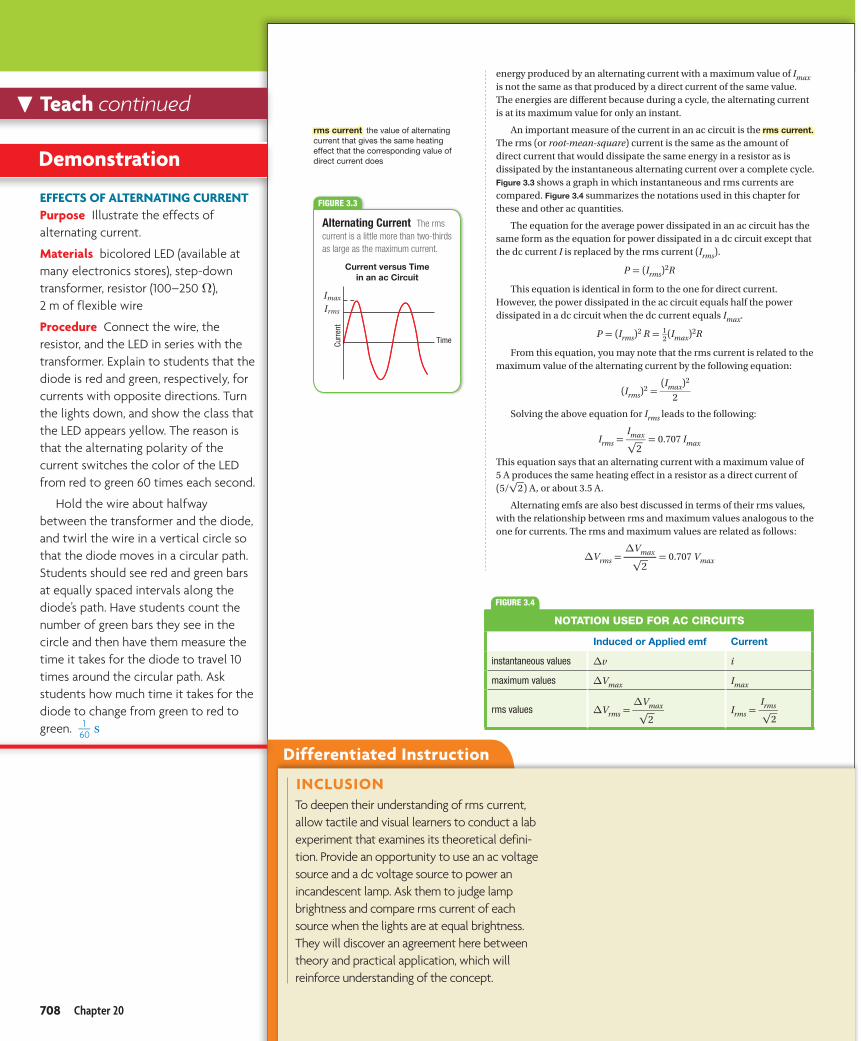
HRW • Holt PhysicsPH99PE-C22-002-009-A
Curr
ent
Time
ImaxIrms
energy produced by an alternating current with a maximum value of Imax is not the same as that produced by a direct current of the same value. The energies are different because during a cycle, the alternating current is at its maximum value for only an instant.
An important measure of the current in an ac circuit is the rms current. The rms (or root-mean-square) current is the same as the amount of direct current that would dissipate the same energy in a resistor as is dissipated by the instantaneous alternating current over a complete cycle.Figure 3.3 shows a graph in which instantaneous and rms currents are compared. Figure 3.4 summarizes the notations used in this chapter for these and other ac quantities.
The equation for the average power dissipated in an ac circuit has the same form as the equation for power dissipated in a dc circuit except that the dc current I is replaced by the rms current (Irms).
P = (Irms)2R
This equation is identical in form to the one for direct current. However, the power dissipated in the ac circuit equals half the power dissipated in a dc circuit when the dc current equals Imax.
P = (Irms)2 R = 1 __ 2 (Imax)2R
From this equation, you may note that the rms current is related to the maximum value of the alternating current by the following equation:
(Irms)2 =
(Imax)2
_ 2
Solving the above equation for Irms leads to the following:
Irms = Imax _
√ 2 = 0.707 Imax
This equation says that an alternating current with a maximum value of 5 A produces the same heating effect in a resistor as a direct current of (5/ √ 2 ) A, or about 3.5 A.
Alternating emfs are also best discussed in terms of their rms values, with the relationship between rms and maximum values analogous to the one for currents. The rms and maximum values are related as follows:
∆Vrms = ∆Vmax _
√ 2
= 0.707 Vmax
FIGURE 3.4
NOTATION USED FOR AC CIRCUITS
Induced or Applied emf Current
instantaneous values ∆v i
maximum values ∆Vmax Imax
rms values ∆Vrms = ∆Vmax _
√ 2 Irms =
Irms _
√ 2
rms current the value of alternating current that gives the same heating effect that the corresponding value of direct current does
Alternating Current The rms current is a little more than two-thirds as large as the maximum current.
FIGURE 3.3
Current versus Time in an ac Circuit
Chapter 20708
Untitled-727 708 5/26/2011 9:50:48 AM
Differentiated Instruction
effeCTS of AlTerNATINg CurreNTPurpose Illustrate the effects of alternating current.
Materials bicolored LED (available at many electronics stores), step-down transformer, resistor (100–250 Ω), 2 m of flexible wire
Procedure Connect the wire, the resistor, and the LED in series with the transformer. Explain to students that the diode is red and green, respectively, for currents with opposite directions. Turn the lights down, and show the class that the LED appears yellow. The reason is that the alternating polarity of the current switches the color of the LED from red to green 60 times each second.
Hold the wire about halfway between the transformer and the diode, and twirl the wire in a vertical circle so that the diode moves in a circular path. Students should see red and green bars at equally spaced intervals along the diode’s path. Have students count the number of green bars they see in the circle and then have them measure the time it takes for the diode to travel 10 times around the circular path. Ask students how much time it takes for the diode to change from green to red to green. 1
__ 60 s
Teach continued
Demonstration
INCluSIoNTo deepen their understanding of rms current, allow tactile and visual learners to conduct a lab experiment that examines its theoretical defini-tion. Provide an opportunity to use an ac voltage source and a dc voltage source to power an incandescent lamp. Ask them to judge lamp brightness and compare rms current of each source when the lights are at equal brightness. They will discover an agreement here between theory and practical application, which will reinforce understanding of the concept.
708 Chapter 20

rms Current and emf
Sample Problem B A generator with a maximum output emf of 205 V is connected to a 115 Ω resistor. Calculate the rms potential difference. Find the rms current through the resistor. Find the maximum ac current in the circuit.
ANALYZE Given: ∆Vmax = 205 V R = 115 Ω
Unknown: ∆Vrms = ? Irms = ? Imax = ?
Diagram:
HRW • Holt PhysicsPH99PE-C22-002-010-A
R = 115 Ω
= 205 VmaxV∆
PLAN Choose an equation or situation: Use the equation for the rms potential difference to find ∆Vrms.
∆Vrms = 0.707 ∆Vmax
Rearrange the definition for resistance to calculate Irms.
Irms = ∆Vrms _
R
Use the equation for rms current to find Imax.
Irms = 0.707 Imax
Rearrange the equation to isolate the unknown:Rearrange the equation relating rms current to maximum current so that maximum current is calculated.
Imax = Irms _
0.707
SOLVE Substitute the values into the equation and solve:
∆Vrms = (0.707)(205 V) = 145 V
Irms = 145 V _ 115 Ω
= 1.26 A
Imax = 1.26 A _ 0.707
= 1.78 A
∆Vrms = 145 V
Irms = 1.26 A
Imax = 1.78 A
CHECK YOUR WORK
The rms values for the emf and current are a little more than two-thirds the maximum values, as expected.
Continued
Rearrange the definition for resistance to calculate IrmsIrmsI .
Interactive DemoHMDScience.com
PREMIUM CONTENT
Tips and TricksBecause emf is measured in volts, maximum emf is frequently abbreviated as ∆Vmax, and rms emf can be abbreviated as ∆Vrms.
Electromagnetic Induction 709
Untitled-727 709 5/26/2011 9:50:48 AM
Problem Solving
Classroom PracticerMS CurreNT AND eMfA generator supplies 110 V rms to a 25 Ω circuit. What is the maximum current supplied to the circuit?
Answer: 6.2 A
INDuCeD eMfPurpose Show that induced emf depends on the number of turns of wire.
Materials 9 V battery, knife switch, 30 cm (or longer) iron bar, two (or more) flashlight bulbs in holders, three connecting wires (each about 1 m long)
Procedure Set up the primary coil before class by connecting the battery and switch in series with one of the wires coiled around the iron bar. Set up two secondary coils, one with 25 turns of wire and one with 50 turns of wire, each in series with a flashlight bulb. Close the switch, and have students compare the brightness of the two bulbs. You may wish to open and close the switch several times for repeated observations.
Demonstration
DeCoNSTruCTINg ProBleMSStudents should read rms current and emf problems carefully to determine what the question is asking them to calculate. Word problems often present a story that seems to complicate the calculation. When they first look at the problem, students should write down any specific values mentioned and then chose the correct equation.
Electromagnetic Induction 709

rms Current and emf (continued)
1. What is the rms current in a light bulb that has a resistance of 25 Ω and an rms emf of 120 V? What are the maximum values for current and emf?
2. The current in an ac circuit is measured with an ammeter. The meter gives a reading of 5.5 A. Calculate the maximum ac current.
3. A toaster is plugged into a source of alternating emf with an rms value of 110 V. The heating element is designed to convey a current with a peak value of 10.5 A. Find the following:
a. the rms current in the heating element
b. the resistance of the heating element
4. An audio amplifier provides an alternating rms emf of 15.0 V. A loudspeaker connected to the amplifier has a resistance of 10.4 Ω. What is the rms current in the speaker? What are the maximum values of the current and the emf?
5. An ac generator has a maximum emf output of 155 V.
a. Find the rms emf output.
b. Find the rms current in the circuit when the generator is connected to a 53 Ω resistor.
6. The largest emf that can be placed across a certain capacitor at any instant is 451 V. What is the largest rms emf that can be placed across the capacitor without damaging it?
Resistance influences current in an ac circuit.The ac potential difference (commonly called the voltage) of 120 V measured from an electrical outlet is actually an rms emf of 120 V. (This, too, is a simplification that assumes that the voltmeter has infinite resistance.) A quick calculation shows that such an emf has a maximum value of about 170 V.
The resistance of a circuit modifies the current in an ac circuit just as it does in a dc circuit. If the definition of resistance is valid for an ac circuit, the rms emf across a resistor equals the rms current multiplied by the resistance. Thus, all maximum and rms values can be calculated if only one current or emf value and the circuit resistance are known.
Ammeters and voltmeters that measure alternating current are calibrated to measure rms values. In this chapter, all values of alternating current and emf will be given as rms values unless otherwise noted. The equations for ac circuits have the same form as those for dc circuits when rms values are used.
Chapter 20710
Untitled-727 710 5/26/2011 9:50:49 AM
Problem Solving
ProBleM guIDe BUse this guide to assign problems.
Se = Student Edition Textbook
Pw = Sample Problem Set I (online)
PB = Sample Problem Set II (online)
Solving for:
∆V Se Sample, 1, 4, 5a, 6; Ch. Rvw. 25–28
Pw Sample, 4–6
PB Sample, 1, 4–6, 9
I Se Sample, 1–2, 3a, 4, 5b; Ch. Rvw. 26–28
Pw Sample, 1–5, 7
PB Sample, 1–5, 7, 8–10
R Se 3b
Pw 3, 5
PB 3, 5
P Se Ch. Rvw. 27
Pw Sample, 1
PB 8–10
*Challenging Problem
AnswersPractice B 1. 4.8 A; 6.8 A, 170 V
2. 7.8 A
3. a. 7.42 A
b. 14.8 Ω
4. 1.44 A; 2.04 A, 21.2 V
5. a. 1.10 × 10² V
b. 2.1 A
6. 319 V
Teach continued
DeCoNSTruCTINg ProBleMSReview Practice Problem 6 with students who need help. In this case, two values are men-tioned: emf (which is given) and rms emf (which is unknown). It is stated that 451 V is the largest emf, so that would mean it is the maximum emf. The students are being asked to determine largest (a.k.a. maximum) rms by relating it to emf. This tells them that they need to use an equation that does so.
710 Chapter 20

HRW • Holt PhysicsPH99PE-C22-003-002-A
Soft iron core
Primary(input)
R
Secondary(output)
1V∆ 2V∆2N1N
TransformersIt is often desirable or necessary to change a small ac applied emf to a larger one or to change a large applied emf to a smaller one. The device that makes these conversions possible is the transformer.
In its simplest form, an ac transformer consists of two coils of wire wound around a core of soft iron, like the apparatus for the Faraday experiment. The coil on the left in Figure 3.5 has N1 turns and is connected to the input ac potential difference source. This coil is called the primary winding, or the primary. The coil on the right, which is connected to a resistor R and consists of N2 turns, is the secondary. As in Faraday’s experiment, the iron core “guides” the magnetic field lines so that nearly all of the field lines pass through both of the coils.
Because the strength of the magnetic field in the iron core and the cross-sectional area of the core are the same for both the primary and secondary windings, the measured ac potential differences across the two windings differ only because of the different number of turns of wire for each. The applied emf that gives rise to the changing magnetic field in the primary is related to that changing field by Faraday’s law of induction.
∆V1 = −N1 ∆ΦM _
∆t
Similarly, the induced emf across the secondary coil is
∆V2 = −N2 ∆ΦM _
∆t
Taking the ratio of ∆V1 to ∆V2 causes all terms on the right side of both equations except for N1 and N2 to cancel. This result is the transformer equation.
Transformer Equation
∆V2 = N2 _ N1
∆V1
induced emf in secondary =
( number of turns in secondary
___ number of turns in primary
) applied emf in primary
Another way to express this equation is to equate the ratio of the potential differences to the ratio of the number of turns.
∆V2 _ ∆V1
= N2 _ N1
When N2 is greater than N1, the secondary emf is greater than that of the primary, and the transformer is called a step-up transformer. When N2 is less than N1, the secondary emf is less than that of the primary, and the transformer is called a step-down transformer.
transformer a device that increases or decreases the emf of alternating current
Basic Components of an ac Transformer A transformer uses the alternating current in the primary circuit to induce an alternating current in the secondary circuit.
FIGURE 3.5
Electromagnetic Induction 711
Untitled-727 711 5/26/2011 9:50:49 AM
Differentiated Instruction
TrANSforMerSPurpose Show students how a trans-former works, and reinforce the idea that a changing current is required.
Materials iron bar, 9 V battery, knife switch, flashlight bulb in holder, two 1 m long wires
Procedure Set up the primary side of the transformer before class by connecting the battery and switch in series with one of the wires coiled around the iron bar. The primary coil should have 50 turns. Set up the secondary coil with 25 turns, and connect the flashlight bulb to the secondary coil.
In class, demonstrate this step-down transformer by momentarily closing the switch and then opening it again. Have students discuss the transfer of energy that occurs in this situation.
Close the switch, and keep it closed. Have students note the behavior of the bulb. Discuss the brief illumination and fading of the bulb with students. Lead students to consider the concept of changing current. Open the switch, and note the illumination. Discuss this effect.
Teaching TipSome students may wonder whether dc transformers are possible. The dc produced by a battery would not work with a transformer. The reason is that a changing current is required, and a battery generates a steady direct current. However, a generator can produce a fluctuating direct current. Such a current could be used by a transformer.
Demonstration
Below leVelRemind students that flux through multiple loops is equal to the flux through one loop times the number of loops. If one loop has an area A, two loops would have an area of
A+A, or 2A. Three loops would have an area of A+A+A, or 3A. and so on. Transformers work because the flux is the same for both parts of the transformer, but the number of loops is different, so the induced emf is different from the original emf.
Electromagnetic Induction 711

It may seem that a transformer provides something for nothing. For example, a step-up transformer can change an applied emf from 10 V to 100 V. However, the power output at the secondary is, at best, equal to the power input at the primary. In reality, energy is lost to heating and radiation, so the output power will be less than the input power. Thus, an increase in induced emf at the secondary means that there must be a proportional decrease in current.
Transformers
Sample Problem C A step-up transformer is used on a 120 V line to provide a potential difference of 2400 V. If the primary has 75 turns, how many turns must the secondary have?
ANALYZE Given: ∆V1 = 120 V ∆V2 = 2400 V N1 = 75 turns
Unknown: N2 = ?
Diagram:
HRW • Holt PhysicsPH99PE-C22-003-004-A
= 120 V1V∆ = 2400 V
2V∆
75 turns = ?2N
=1N
PLAN Choose an equation or situation: Use the transformer equation.
∆V2 = N1 _ N2
∆V1
Rearrange the equation to isolate the unknown:
N2 = ∆V2 _ ∆V1
N1
SOLVE Substitute the values into the equation and solve:
N2 = ( 2400 V _ 120 V
) 75 turns = 1500 turns
N2 = 1500 turns
CHECK YOUR WORK
The greater number of turns in the secondary accounts for the increase in the emf in the secondary. The step-up factor for the transformer is 20:1.
Continued
PREMIUM CONTENT
Interactive DemoHMDScience.com
Chapter 20712
Untitled-727 712 5/26/2011 9:50:50 AM
Problem Solving
Classroom PracticeTrANSforMerSA transformer has 75 turns on the primary and 1500 turns on the secondary.
a. If the potential difference across the primary is 120 V, what is the potential difference across the secondary?
b. If the transformer has 1625 turns on the secondary instead of 1500, what is the potential difference across the secondary?
Answers: a. 2400 V b. 2600 V
Teach continued
reAlITy CheCkStudents should keep in mind that the number of turns in a coil and emf are directly propor-tional. If the number of turns in the secondary coil is greater than in the primary coil, the induced emf will be greater than the original emf. If the number of turns decreases, induced emf will decrease. Students should double-check their answers to see that the answers correspond to this proportional relationship.
712 Chapter 20

Transformers (continued)
1. A step-down transformer providing electricity for a residential neighborhood has exactly 2680 turns in its primary. When the potential difference across the primary is 5850 V, the potential difference at the secondary is 120 V. How many turns are in the secondary?
2. A step-up transformer used in an automobile has a potential difference across the primary of 12 V and a potential difference across the secondary of 2.0 × 10⁴ V. If the number of turns in the primary is 21, what is the number of turns in the secondary?
3. A step-up transformer for long-range transmission of electric power is used to create a potential difference of 119 340 V across the secondary. If the potential difference across the primary is 117 V and the number of turns in the secondary is 25 500, what is the number of turns in the primary?
4. A potential difference of 0.750 V is needed to provide a large current for arc welding. If the potential difference across the primary of a step-down transformer is 117 V, what is the ratio of the number of turns of wire on the primary to the number of turns on the secondary?
5. A step-down transformer has 525 turns in its secondary and 12 500 turns in its primary. If the potential difference across the primary is 3510 V, what is the potential difference across the secondary?
Real transformers are not perfectly efficient.The transformer equation assumes that no power is lost between the transformer’s primary and secondary coils. Real transformers typically have efficiencies ranging from 90 percent to 99 percent. Power is lost because of the small currents induced by changing magnetic fields in the transformer’s iron core and because of resistance in the wires of the windings.
The power lost to resistive heating in transmission lines varies as I2R. To minimize I2R loss and maximize the deliverable energy, power companies use a high emf and a low current when transmitting power over long distances. By reducing the current by a factor of 10, the power loss is reduced by a factor of 100. In practice, the emf is stepped up to around 230 000 V at the generating station, is stepped down to 20 000 V at a regional distribution station, and is finally stepped down to 120 V at the customer’s utility pole. The high emf in long-distance transmission lines makes the lines especially dangerous when high winds knock them down.
Electromagnetic Induction 713
Untitled-727 713 5/26/2011 9:50:51 AM
Differentiated Instruction
ProBleM guIDe CUse this guide to assign problems.
Se = Student Edition Textbook
Pw = Sample Problem Set I (online)
PB = Sample Problem Set II (online)
Solving for:
N Se Sample, 1–3; Ch. Rvw. 35–36
Pw 4–5, 7
PB 6, 8–10
N
1 _ N
2
Se 4; Ch. Rvw. 41
PB 7
∆V Se 5–6; Ch. Rvw. 40
Pw Sample, 1–3, 6b
PB Sample 1–5
I Pw 6a, 7
PB 10
*Challenging Problem
AnswersPractice C 1. 55 turns
2. 3.5 × 10⁴ turns
3. 25 turns
4. 156:1
5. 147 V
Below leVelTo help students understand why increasing the voltage for a given power decreases the power loss, remind students that power can also be calculated by multiplying the potential difference by the current. For the same power, increasing the potential difference decreases the current, and thus decreases the power loss over the length of the wires.
Electromagnetic Induction 713

–+
12 V battery
Step-up transfomer (ignition coil)
Spark plug
Ignitionswitch
Computer
Crank anglesensor
Reviewing Main Ideas
1. The rms current that a single coil of an electric guitar produces is 0.025 mA. The coil’s resistance is 4.3 kΩ. What is the maximum instan-taneous current? What is the rms emf produced by the coil? What is the maximum emf produced by the coil?
2. A step-up transformer has exactly 50 turns in its primary and exactly 7000 turns in its secondary. If the applied emf in the primary is 120 V, what emf is induced in the secondary?
3. A television picture tube requires a high potential difference, which a step-up transformer provides in older models. The transformer has 12 turns in its primary and 2550 turns in its secondary. If 120 V is applied across the primary, what is the output emf?
Critical Thinking
4. What is the average value of current over one cycle of an ac signal? Why, then, is a resistor heated by an ac current?
The ignition coil in a gasoline engine is a transformer.An automobile battery provides a constant emf of 12 dc volts to power various systems in your automobile. The ignition system uses a transformer, called the ignition coil, to convert the car battery’s 12 dc volts to a potential difference that is large enough to cause sparking between the gaps of the spark plugs. The diagram in Figure 3.6 shows a type of ignition system that has been used in automobiles since about 1990. In this arrangement, called an electronic ignition, each cylinder has its own transformer coil.
The ignition system on your car has to work in perfect concert with the rest of the engine. The goal is to ignite the fuel at the exact moment when the expanding gases can do the maximum amount of work. A photoelectric detector, called a crank angle sensor, uses the crankshaft’s position to determine when the cylinder’s con-tents are near maximum compression.
The sensor then sends a signal to the automobile’s computer. Upon receiving this signal, the computer closes the primary circuit to the cylinder’s coil, causing the current in the primary to rapidly increase. As we learned earlier in this chapter, the increase in current induces a rapid change in the magnetic field of the trans-former. Because the change in magnetic field on the primary side is so quick, the change induces a very large emf, from 40 000 to 100 000 V. The emf is applied across the spark plug and creates a spark that ignites and burns the fuel that powers your automobile.
A Step-Up Transformer in an Auto Ignition System The transformer in an automobile engine raises the potential difference across the gap in a spark plug so that sparking occurs.
FIGURE 3.6
Chapter 20714
SECTION 3 FORMATIVE ASSESSMENT
Untitled-727 714 5/26/2011 9:50:51 AM
Answers to Section Assessment
Teaching TipPoint out to students that spark plugs create a spark because the potential difference across the gap increases by up to 10 000 V. At such high potential differences, air is ionized and becomes a conductor.
Assess Use the Formative Assessment on this page to evaluate student mastery of the section.
reteach For students who need additional instruction, download the Section Study Guide.
response to Intervention To reassess students’ mastery, use the Section Quiz, available to print or to take directly online at hMDScience.com.
Teach continued
Assess and Reteach
1. 0.035 mA; 0.11 V; 0.15 V
2. 1.7 × 10⁴ V
3. 2.6 × 10⁴ V
4. zero; The current is positive for exactly the same amount of time that it is negative. The direction of current (positive or negative) does not affect the heating of the resistor. That is, the resistor is being heated throughout the cycle whether the current is positive or negative.
714 Chapter 20

©In
frare
d Pr
oces
sing
and
Ana
lysi
s Ce
nter
, Cal
iforn
ia In
stitu
te o
f Tec
hnol
ogy
Electromagnetic WavesKey Termselectromagnetic radiation photon
Propagation of Electromagnetic WavesLight is a phenomenon known as an electromagnetic wave. As the name implies, oscillating electric and magnetic fields create electromagnetic waves. In this section, you will learn more about the nature and the discovery of electromagnetic waves.
The wavelength and frequency of electromagnetic waves vary widely, from radio waves with very long wavelengths to gamma rays with extremely short wavelengths. The visible light that our eyes can detect occupies an intermediate range of wavelengths. Familiar objects “look” quite different at different wavelengths. Figure 4.1 shows how a person might appear to us if we could see beyond the red end of the visible spectrum.
In this chapter, you have learned that a changing magnetic field can induce a current in a circuit (Faraday’s law of induction). From Coulomb’s law, which describes the electrostatic force between two charges, you know that electric field lines start on positive charges and end at negative charges. On the other hand, magnetic field lines always form closed loops and have no beginning or end. Finally, you learned in the chapter on magnetism that a magnetic field is created around a current-carrying wire, as stated by Ampere’s law.
Electromagnetic waves consist of changing electric and magnetic fields.In the mid-1800s, Scottish physicist James Clerk Maxwell created a simple but sophisticated set of equations to describe the relationship between electric and magnetic fields. Maxwell’s equations summarized the known phenomena of his time: the observations that were described by Coulomb, Faraday, Ampere, and other scientists of his era. Maxwell believed that nature is symmetric, and he hypothesized that a changing electric field should produce a magnetic field in a manner analogous to Faraday’s law of induction.
Maxwell’s equations described many of the phenomena, such as magnetic induction, that had already been observed. However, other phenomena that had not been observed could be derived from the equations. For example, Maxwell’s
Objectives
Describe what electromagnetic waves are and how they are produced.
Recognize that electricity and magnetism are two aspects of a single electromagnetic force.
Explain how electromagnetic waves transfer energy.
Describe various applications of electromagnetic waves.
Infrared Image of a Person At normal body temperature, humans radiate most strongly in the infrared, at a wavelength of about 10 microns (10−5 m). The wavelength of the infrared radiation can be correlated to temperature.
FIGURE 4.1
Electromagnetic Induction 715
SECTION 4
Untitled-728 715 5/26/2011 9:51:28 AM
Differentiated Instruction
Preview VocabularyLatin Word Origins The term radiation comes from the Latin radiare, meaning “to shine or beam.” Since shining and beaming are two actions associated with light, students can use this root to help them remember that electromagnetic radiation happens at the speed of light.
FIGURE 4.1 Explain to students that the colors in the infrared photograph are added to provide contrast between the different parts of the image so that the parts can be easily seen in the visible spectrum. Point out that all images that are obtained using non-visible electro-magnetic radiation show only light and dark areas, as in a black-and-white photograph. The stronger that radiation is in a particular part of the image, the greater the exposure is in that part of the image. False color is often added later to these images.
Ask From which parts of the person is the most infrared radiation emitted?
Answer: The neck, eyes, and forehead emit the most infrared radiation.
Ask From which parts of the person is the least infrared radiation emitted?
Answer: The nose and hair emit the least infrared radiation.
Plan and Prepare
Teach
TEACH FROM VISUALS
IncLUsIOnDiscussion and understanding of colors can be a challenge for students who have vision impairments, such as blindness or color blindness. For these students, focus on the frequency, wavelength, and energy of certain electromagnetic waves. For color blind students, make sure you use colors that are less likely to be a problem for these students.
Electromagnetic Induction 715
sEcTIOn 4

PHYSICSSpec. Number PH 99 PE C14-001-002-ABoston Graphics, Inc.617.523.1333
Oscillating magnetic field
Oscillating electric field
Direction of the electromagnetic wave
(tr) ©
Big
Bear
Sol
ar O
bser
vato
ry/N
ew J
erse
y In
stitu
te o
f Tec
hnol
ogy;
(tc)
©Na
tiona
l Sol
ar O
bser
vato
ry/A
URA/
NSF;
(bl),
(bc)
©Co
urte
sy o
f SOH
O/EI
T co
nsor
tium
. SOH
O is
a p
roje
ct o
f int
erna
tiona
l coo
pera
tion
betw
een
ESA
and
NASA
.; (tl
) ©Th
e No
beya
ma
Radi
o Ob
serv
ator
y; (b
r) ©
Yohk
oh S
olar
Obs
erva
tory
equations predicted that a changing magnetic field would create a changing electric field, which would, in turn, create a changing magnetic field, and so on. The predicted result of those changing fields is a wave that moves through space at the speed of light.
Maxwell predicted that light was electromagnetic in nature. The scientific community did not immediately accept Maxwell’s equations. However, in 1887, a German physicist named Heinrich Hertz generated and detected electromagnetic waves in his laboratory. Hertz’s experi-mental confirmation of Maxwell’s work convinced the scientific community to accept the work.
Electromagnetic waves are simply oscillating electric and magnetic fields. The electric and magnetic fields are at right angles to each other and also at right angles to the direction that the wave is moving. Figure 4.2 is a simple illustration of an electromagnetic wave at a single point in time. The electric field oscillates back and forth in one plane while the magnetic field oscillates back and forth in a perpendicular plane. The wave travels in the direc-tion that is perpendicular to both of the oscillating fields. In the chapter on vibrations and waves you learned that this kind of wave is called a transverse wave.
Electric and magnetic forces are aspects of a single force.Although magnetism and electricity seem like very different things, we know that both electric and magnetic fields can produce forces on charged particles. These forces are aspects of one and the same force, called the electromagnetic force. Physicists have identified four fundamen-tal forces in the universe: the strong force, which holds together the nucleus of an atom; the electromagnetic force, which is discussed here; the weak force, which is involved in nuclear decay; and the gravitational force, discussed in the chapter “Circular Motion and Gravitation.” In the 1970s, physicists came to regard the electromagnetic and the weak force as two aspects of a single electroweak interaction.
The electromagnetic force obeys the inverse-square law. The force’s magnitude decreases as one over the distance from the source squared. The inverse-square law applies to phenomena—such as gravity, light, and sound—that spread their influence equally in all directions and with an infinite range.
All electromagnetic waves are produced by accelerating charges.The simplest radiation source is an oscillating charged particle. Consider a negatively charged particle (electron) moving back and forth beside a fixed positive charge (proton). Recall that the changing electric field induces a magnetic field perpendicular to the electric field. In this way, the wave propagates itself as each changing field induces the other.
An Electromagnetic Wave An electromagnetic wave consists of electric and magnetic field waves at right angles to each other. The wave moves in the direction perpendicular to both oscillating waves.
FIGURE 4.2
Chapter 20716
Untitled-728 716 5/26/2011 9:51:29 AM
Differentiated Instruction
Teaching TipExplain to students that one can take the product of the electric and magnetic field strengths to determine the power that electromagnetic radiation transmits. Because the electro-magnetic radiation moves in a direction perpendicular to both the electric and magnetic fields, the power radiated is a vector quantity. This vector is called the Poynting vector, after the English physicist John Henry Poynting.
Teach continued
BELOW LEVELLight waves tie together many of the concepts students have previously learned about electricity and magnetism. Remind students that a moving charge creates a magnetic field. If a charge vibrates, changing the direction in which it moves, it creates a changing magnetic field. The changing magnetic induces a changing electric field, which causes a changing magnetic field, and so on..
716 Chapter 20
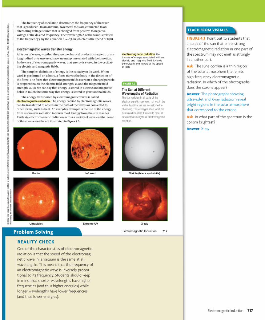
(tr) ©
Big
Bear
Sol
ar O
bser
vato
ry/N
ew J
erse
y In
stitu
te o
f Tec
hnol
ogy;
(tc)
©Na
tiona
l Sol
ar O
bser
vato
ry/A
URA/
NSF;
(bl),
(bc)
©Co
urte
sy o
f SOH
O/EI
T co
nsor
tium
. SOH
O is
a p
roje
ct o
f int
erna
tiona
l coo
pera
tion
betw
een
ESA
and
NASA
.; (tl
) ©Th
e No
beya
ma
Radi
o Ob
serv
ator
y; (b
r) ©
Yohk
oh S
olar
Obs
erva
tory
The frequency of oscillation determines the frequency of the wave that is produced. In an antenna, two metal rods are connected to an alternating voltage source that is changed from positive to negative voltage at the desired frequency. The wavelength λ of the wave is related to the frequency f by the equation λ = c/f, in which c is the speed of light.
Electromagnetic waves transfer energy.All types of waves, whether they are mechanical or electromagnetic or are longitudinal or transverse, have an energy associated with their motion. In the case of electromagnetic waves, that energy is stored in the oscillat-ing electric and magnetic fields.
The simplest definition of energy is the capacity to do work. When work is performed on a body, a force moves the body in the direction of the force. The force that electromagnetic fields exert on a charged particle is proportional to the electric field strength, E, and the magnetic field strength, B. So, we can say that energy is stored in electric and magnetic fields in much the same way that energy is stored in gravitational fields.
The energy transported by electromagnetic waves is called electromagnetic radiation. The energy carried by electromagnetic waves can be transferred to objects in the path of the waves or converted to other forms, such as heat. An everyday example is the use of the energy from microwave radiation to warm food. Energy from the sun reaches Earth via electromagnetic radiation across a variety of wavelengths. Some of these wavelengths are illustrated in Figure 4.3.
The Sun at Different Wavelengths of Radiation The sun radiates in all parts of the electromagnetic spectrum, not just in the visible light that we are accustomed to observing. These images show what the sun would look like if we could “see” at different wavelengths of electromagnetic radiation.
FIGURE 4.3
electromagnetic radiation the transfer of energy associated with an electric and magnetic field; it varies periodically and travels at the speed of light
Radio Infrared Visible (black and white)
Ultraviolet Extreme UV X-ray
Electromagnetic Induction 717
Untitled-728 717 5/26/2011 9:51:30 AM
Problem solving
FIGURE 4.3 Point out to students that an area of the sun that emits strong electromagnetic radiation in one part of the spectrum may not emit as strongly in another part.
Ask The sun’s corona is a thin region of the solar atmosphere that emits high-frequency electromagnetic radiation. In which of the photographs does the corona appear?
Answer: The photographs showing ultraviolet and X-ray radiation reveal bright regions in the solar atmosphere that correspond to the corona.
Ask In what part of the spectrum is the corona brightest?
Answer: X-ray
TEACH FROM VISUALS
REALITy chEckOne of the characteristics of electromagnetic radiation is that the speed of the electromag-netic wave in a vacuum is the same at all wavelengths. This means that the frequency of an electromagnetic wave is inversely propor-tional to its frequency. Students should keep in mind that shorter wavelengths have higher frequencies (and thus higher energies) while longer wavelengths have lower frequencies (and thus lower energies).
Electromagnetic Induction 717

©W
illia
m B
. Plo
wm
an/A
P Im
ages
High-energy electromagnetic waves behave like particles.Sometimes an electromagnetic wave behaves like a particle. This notion is called the wave-particle duality of light. It is important to understand that there is no difference in what light is at different frequencies. The difference lies in how light behaves.
When thinking about electromagnetic waves as a stream of particles, it is helpful to utilize the concept of a photon. A photon is a particle that carries energy but has zero mass. You will learn more about photons in the chapter on atomic physics. The relationship between frequency and photon energy is simple: E = hf, in which h, Plank’s constant, is a fixed number and f is the frequency of the wave.
Low-energy photons tend to behave more like waves, and higher energy photons behave more like particles. This distinction helps scientists design detectors and telescopes to distinguish different frequencies of radiation.
Y ou are listening to 97.7 WKID, student-run radio from Central High School.” What does the radio announcer mean by this greeting? Where do
those numbers and letters come from? The numbers mean that the radio station is broadcasting a frequency modulated (FM) radio signal of 97.7 megahertz (MHz). In other words, the electric and magnetic fields of the radio wave are changing back and forth between their minimum and maximum values 97 700 000 times per second. That’s a lot of oscillations in a three-minute-long song!
The Federal Communications Commission (FCC) assigns the call letters, such as WKID, and the frequencies that the various stations will use. All FM radio stations are located in the band of frequencies that range from 88 to 108 MHz.
Similarly, amplitude modulated (AM) radio stations are all in the 535 to 1700 kHz band. A kilohertz (kHz) is 1000 cycles per second, so the AM band is broadcast at lower frequencies than the FM band is. The television channels 2 to 6 broadcast between 54 MHz and 88 MHz. Channels 7 to 13 are in the 174 MHz to 220 MHz band, and the remaining channels occupy even higher frequency bands in the spectrum.
How are these radio waves transmitted? To create a simple radio transmitter, you need to create a rapidly changing electric current in a wire. The easiest form of a changing current is a sine wave. A sine wave can be created with a few simple circuit components, such as a capacitor and an inductor. The wave is amplified, sent to an antenna, and transmitted into space.
If you have a sine wave generator and a transmitter, you have a radio station. The only problem is that a sine wave contains very little information! To turn sound waves or pictures into information that your radio or television set can interpret, you need to change, or modulate, the signal. This modulation is done by slightly changing the frequency based on the information that you want to send. FM radio stations and the sound part of your TV signal convey information using this method.
Radio and TV Broadcasts
photon a unit or quantum of light; a particle of electromagnetic radiation that has zero mass and carries a quantum of energy
“
Chapter 20718
Untitled-728 718 5/26/2011 9:51:33 AM
Differentiated Instruction
Why It MattersRADIO AnD TV BROADcAsTsIn 1920, Reginald Fessenden accomplished the first modulation of radio waves by sound signals. The basic principle of transmitting sound by radio waves, or radiotelephony, involved imposing the waveform of a sound signal onto a radio carrier wave. Because sound waves have a much lower frequency than radio waves do, the amplitude or frequency of the carrier wave can be compressed or expanded (modulated) to the general shape of the sound signal.
Amplitude modulation (AM), which uses lower-frequency radio waves, often takes advantage of the ionosphere. This region of the atmosphere reflects the lower-frequency radio waves, giving them a greater broadcast range. Some high-power AM stations can be received in distant parts of the world.
Frequency modulation (FM) has the advantage of being less susceptible to interference either from other stations at the same frequency or static. However, FM’s shorter wavelengths do not reflect off the atmosphere, so they cannot be picked up over the horizon.
The Language of PhysicsIn 1926, the American physical chemist Gilbert N. Lewis introduced the word photon.
Teach continued
PRE-APStudents should recall that light was thought to be particles until Huygens provided evidence for diffraction in the nineteenth century. Because of his work, the wave theory became accepted. Then in 1905, Einstein published a theory explaining the photoelectric effect. He theorized that light travels in massless bundles. Have students research the evidence for wave and particle behavior for light.
718 Chapter 20

Wavelength(m)
Commonname ofwave
One wavelengthabout the samesize as a...
Frequency(Hz)
longer
radio waves
infrared
microwaves
visible
X rays
gamma raysultraviolet
shorter
higherlower
footballeld
humanbeing
soccerball
needle red bloodcell
microchiptransistor
DNAmolecule
atomicnucleus
C20004005_A
103 102 101 10-1 10-2 10-3 10-4 10-5 10-6 10-7 10-8 10-9 10-10 10-11 10-121
10 6 10 7 10 8 10 9 1010 1011 1012 1013 1014 1015 1016 1017 1018 1019 1020
©W
illia
m B
. Plo
wm
an/A
P Im
ages
The Electromagnetic SpectrumAt first glance, radio waves seem completely different from visible light and gamma rays. They are produced and detected in very different ways. Though your eyes can see visible light, a large antenna is needed to detect radio waves, and sophisticated scientific equipment must be used to observe gamma rays. Even though they appear quite different, all the different parts of the electromagnetic spectrum are fundamentally the same thing. They are all electromagnetic waves.
The electromagnetic spectrum can be expressed in terms of wave-length, frequency, or energy. The electromagnetic spectrum is shown in Figure 4.4. Longer wavelengths, like radio waves, are usually described in terms of frequency. If your favorite FM radio station is 90.5, the frequency is 90.5 MHz (9.05 × 10⁷ Hz). Infrared, visible, and ultraviolet light are usually described in terms of wavelength. We see the wavelength 670 nm (6.70 × 10⁻⁷ m) as red light. The shortest wavelength radiation is gener-ally described in terms of the energy of one photon. For example, the element cesium-137 emits gamma rays with energy of 662 keV (10−13 J). (A keV is a kilo-electron volt, equal to 1000 eV or 1.60 × 10⁻¹⁶ J.)
Radio waves.Radio waves have the longest wavelengths in the spectrum. The wave-lengths range in size from the diameter of a soccer ball to the length of a soccer field and beyond. Because long wavelengths easily travel around objects, they work well for transmitting information long distances. In the United States, the FCC regulates the radio spectrum by assigning the bands that certain stations can use for radio and television broadcasting.
Objects that are far away in deep space also emit radio waves. Because these waves can pass through Earth’s atmosphere, scientists can use huge antennas on land to collect the waves, which can help them understand the nature of the universe.
The Electromagnetic Spectrum The electromagnetic spectrum ranges from very long radio waves, with wavelengths equal to the height of a tall building, to very short-wavelength gamma rays, with wavelengths as short as the diameter of the nucleus of an atom.
FIGURE 4.4
Electromagnetic Induction 719
Untitled-728 719 5/26/2011 9:51:33 AM
VAn DE GRAAFF GEnERATORPurpose To show how an electric charge that is moving between surfaces produces electromagnetic radiation in the radio part of the spectrum.
Materials Van de Graaff generator, metal rod with insulated handle, portable radio
Procedure Turn the radio on and tune it to a part of the AM band where there is no channel and very little noise. Turn up the volume and place the radio several meters away from the Van de Graaff generator. Turn on the generator, hold the insulated end of the metal rod, and bring the opposite end of the rod close to the sphere of the generator. Have students notice that the radio clicks each time that a spark jumps between the generator and the rod. Explain that the sparks consist of changing electric currents, which produce changing electric and magnetic fields and thus electromagnetic waves.
Demonstration
BELOW LEVELStudents may think that radio waves are always associated with sound. Remind them that modulated radio waves in the FM part of the spectrum provide the picture component of a broadcast television signal. You can also mention that radio astronomy involves “seeing” rather than “listening” at very long electromagnetic wavelengths.
Electromagnetic Induction 719

Libr
ary
of C
ongr
ess,
Prin
ts a
nd P
hoto
grap
hs D
ivis
ion
[LC-
USZ6
2-95
345]
©Be
at G
lanz
man
n/Co
rbis
The Visible Light Spectrum When white light shines through a prism or through water, such as in this rainbow, you can see the colors of the visible light spectrum.
FIGURE 4.5
Microwaves.The wavelengths of microwaves range from 30 cm to 1 mm in length. These waves are considered to be part of the radio spectrum and are also regulated by the FCC. Microwaves are used to study the stars, to talk with satellites in orbit, and to heat up your after-school snack.
Microwave ovens use the longer-wavelength microwaves to cook your popcorn quickly. Microwaves are also useful for transmitting information because they can penetrate mist, clouds, smoke, and haze. Microwave towers throughout the world convey telephone calls and computer data from city to city. Shorter-wavelength microwaves are used for radar. Radar works by sending out bursts of microwaves and detecting the reflections off of objects the waves hit.
Infrared.Infrared light lies between the microwave and the visible parts of the electromagnetic spectrum. The far-infrared wavelengths, which are close to the microwave end of the spectrum, are about the size of the head of a pin. Short, near-infrared wavelengths are microscopic. They are about the size of a cell.
You experience far-infrared radiation every day as heat given off by anything warm: sunlight, a warm sidewalk, a flame, and even your own body! Television remote controls and some burglar alarm systems use near-infrared radiation. Night-vision goggles show the world as it looks in the infrared, which helps police officers and rescue workers to locate people, animals, and other warm objects in the dark. Mosquitoes can also “see” in the infrared, which is one of the tools in their arsenal for finding dinner.
Visible light.The wavelengths that the human eye can see range from about 700 nm (red light) to 400 nm (violet light). This range is a very small part of the electromagnetic spectrum! We see the visible spectrum as a rainbow, as shown in Figure 4.5.
Visible light is produced in many ways. An incandescent light bulb gives off light—and heat—from a glowing filament. In neon lights and in lasers, atoms emit light directly. Televisions and fluorescent lights make use of phosphors, which are materials that emit light when they are exposed to high-energy electrons or ultraviolet radiation. Fireflies create light through a chemical reaction.
Ultraviolet.Ultraviolet (UV) light has wavelengths that are shorter than visible light, just beyond the violet. Our sun emits light throughout the spectrum, but the ultraviolet waves are the ones responsible for causing sunburns. Even though you cannot see ultraviolet light with your eyes, this light will also damage your retina. Only a small portion of the ultraviolet waves that the sun emits actually penetrates Earth’s atmosphere. Various atmospheric gases, such as ozone, block most of the UV waves.
Chapter 20720
Untitled-728 720 5/26/2011 9:51:36 AM
Differentiated Instruction
Misconception Alert!Students may be perplexed about the bright colors that appear under low-frequency ultraviolet light, or black light. Explain that the materials used in black-light posters absorb ultraviolet radiation and then reemit the energy at longer wavelengths of light. This process, called fluorescence, produces the glowing colors that are seen under the invisible ultraviolet light.
Teach continued
PRE-APExplain to students that one common forms of electromagnetic radiation in the universe is in the microwave region of the spectrum. Hydrogen is the most abundant element in the universe. When a hydrogen electron undergoes a transition from its higher-energy spin state to its lower-energy spin state, the atom emits a photon. The photon has a specific wavelength associated with the energy change of the transition.
This low-energy microwave photon, with a wavelength of 21 cm, occurs in regions of hydrogen clouds where no stars have formed. Because interstellar dust does not readily absorb these waves, this radiation is easily observed throughout the Milky Way galaxy.
720 Chapter 20

Reviewing Main Ideas
1. What concepts did Maxwell use to help create his theory of electricity and magnetism? What phenomenon did Maxwell’s equations predict?
2. What do electric and magnetic forces have in common?
3. The parts of the electromagnetic spectrum are commonly described in one of three ways. What are these ways?
Critical Thinking
4. Where is the energy of an electromagnetic wave stored? Describe how this energy can be used.
Ultraviolet light is often used as a disinfectant to kill bacteria in city water supplies or to sterilize equipment in hospitals. Scientists use ultraviolet light to determine the chemical makeup of atoms and mol-ecules and also the nature of stars and other celestial bodies. Ultraviolet light is also used to harden some kinds of dental fillings.
X rays.As the wavelengths of electromagnetic waves decrease, the associated photons increase in energy. X rays have very short wavelengths, about the size of atoms, and are usually thought of in terms of their energy instead of their wavelength.
While the German scientist Wilhelm Conrad Roentgen was experi-menting with vacuum tubes, he accidentally discovered X rays. A week later, he took an X-ray photograph of his wife’s hand, which clearly revealed her wedding ring and her bones. This first X ray is shown in Figure 4.6. Roentgen called the phenomenon X ray to indicate that it was an unknown type of radiation, and the name remains in use today.
You are probably familiar with the use of X rays in medicine and dentistry. Airport security also uses X rays to see inside luggage. Emission of X rays from otherwise dark areas of space suggests the existence of black holes.
Gamma rays.The shortest-wavelength electromagnetic waves are called gamma rays. As with X rays, gamma rays are usually described by their energy. The highest-energy gamma rays observed by scientists come from the hottest regions of the universe.
Radioactive atoms and nuclear explosions produce gamma rays. Gamma rays can kill living cells and are used in medicine to destroy cancer cells. The universe is a huge generator of gamma rays. Because gamma rays do not fully pierce Earth’s atmosphere, astronomers frequently mount gamma-ray detectors on satellites.
Libr
ary
of C
ongr
ess,
Prin
ts a
nd P
hoto
grap
hs D
ivis
ion
[LC-
USZ6
2-95
345]
©Be
at G
lanz
man
n/Co
rbis
X-ray Image of a Hand Wilhelm Roentgen took this X-ray image of Bertha Roentgen’s hand one week after his discovery of this new type of electromagnetic radiation.
FIGURE 4.6
Electromagnetic Induction 721
SECTION 4 FORMATIVE ASSESSMENT
Untitled-728 721 5/26/2011 9:51:37 AM
Answers to section Assessment
The Language of PhysicsGamma rays, which were first observed by the French physicist P. Villard in 1900, were classified as such by Ernest Rutherford, who had already discovered alpha and beta rays the previous year.
Assess Use the Formative Assessment on this page to evaluate student mastery of the section.
Reteach For students who need additional instruction, download the Section Study Guide.
Response to Intervention To reassess students’ mastery, use the Section Quiz, available to print or to take directly online at hMDscience.com.
Assess and Reteach
1. Maxwell combined the following observations: static electric and magnetic fields, the magnetic field of a current-carrying wire and electromagnetic induction. He also hypothesized that a changing electric field would produce a magnetic field. Maxwell’s equations predicted electromagnetic radiation.
2. Both act on charged particles.
3. frequency, wavelength, and energy of a photon
4. The energy of electromagnetic waves is stored in the electric and magnetic fields that make up the wave. The energy can be added to materials to increase their energy, such as the heating of food.
Electromagnetic Induction 721
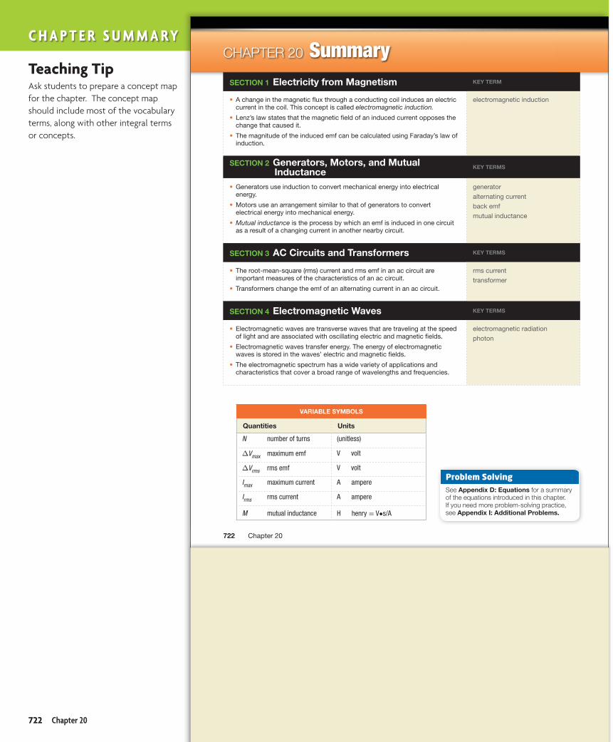
Summary
VARIABLE SYMBOLS
Quantities Units
N number of turns (unitless)
∆Vmax maximum emf V volt
∆Vrms rms emf V volt
Imax maximum current A ampere
Irms rms current A ampere
M mutual inductance H henry = V•s/A
SECTION 1 Electricity from Magnetism KEY TERM
A change in the magnetic flux through a conducting coil induces an electric • current in the coil. This concept is called electromagnetic induction.
Lenz’s law states that the magnetic field of an induced current opposes the • change that caused it.
The magnitude of the induced emf can be calculated using Faraday’s law of • induction.
electromagnetic induction
SECTION 2 Generators, Motors, and Mutual Inductance
KEY TERMS
Generators use induction to convert mechanical energy into electrical • energy.
Motors use an arrangement similar to that of generators to convert • electrical energy into mechanical energy.
Mutual inductance• is the process by which an emf is induced in one circuit as a result of a changing current in another nearby circuit.
generator
alternating current
back emf
mutual inductance
SECTION 3 AC Circuits and Transformers KEY TERMS
The root-mean-square (rms) current and rms emf in an ac circuit are • important measures of the characteristics of an ac circuit.
Transformers change the emf of an alternating current in an ac circuit.•
rms current
transformer
SECTION 4 Electromagnetic Waves KEY TERMS
Electromagnetic waves are transverse waves that are traveling at the speed • of light and are associated with oscillating electric and magnetic fields.
Electromagnetic waves transfer energy. The energy of electromagnetic • waves is stored in the waves’ electric and magnetic fields.
The electromagnetic spectrum has a wide variety of applications and • characteristics that cover a broad range of wavelengths and frequencies.
electromagnetic radiation
photon
Problem SolvingSee Appendix D: Equations for a summary of the equations introduced in this chapter. If you need more problem-solving practice, see Appendix I: Additional Problems.
Chapter 20722
CHAPTER 20
Untitled-723 722 5/26/2011 9:47:12 AM
Teaching TipAsk students to prepare a concept map for the chapter. The concept map should include most of the vocabulary terms, along with other integral terms or concepts.
C h a p t e r s u m m a ry
722 Chapter 20

Electromagnet
emf
Coil
Switch
HRW • Holt PhysicsPH99PE-C22-CHR-001-A
- +
R
B
HRW • Holt PhysicsPH99PE-C22-CHR-002-A
(a) (b)
Review
Electricity from MagnetismREVIEWING MAIN IDEAS
1. Suppose you have two circuits. One consists of an electromagnet, a dc emf source, and a variable resistor that permits you to control the strength of the magnetic field. In the second circuit, you have a coil of wire and a galvanometer. List three ways that you can induce a current in the second circuit.
2. Explain how Lenz’s law allows you to determine the direction of an induced current.
3. What four factors affect the magnitude of the induced emf in a coil of wire?
4. If you have a fixed magnetic field and a length of wire, how can you increase the induced emf across the ends of the wire?
CONCEPTUAL QUESTIONS
5. Rapidly inserting the north pole of a bar magnet into a coil of wire connected to a galvanometer causes the needle of the galvano meter to deflect to the right. What will happen to the needle if you do the following?a. pull the magnet out of the coilb. let the magnet sit at rest in the coilc. thrust the south end of the magnet into the coil
6. Explain how Lenz’s law illustrates the principle of energy conservation.
7. Does dropping a strong magnet down a long copper tube induce a current in the tube? If so, what effect will the induced current have on the motion of the magnet?
8. Two bar magnets are placed side by side so that the north pole of one magnet is next to the south pole of the other magnet. If these magnets are then pushed toward a coil of wire, would you expect an emf to be induced in the coil? Explain your answer.
9. An electromagnet is placed next to a coil of wire in the arrangement shown below. According to Lenz’s law, what will be the direction of the induced current in the resistor R in the following cases?a. The magnetic field suddenly decreases after the
switch is opened.b. The coil is moved closer to the electromagnet.
PRACTICE PROBLEMS
For problems 10–12, see Sample Problem A.
10. A flexible loop of conducting wire has a radius of 0.12 m and is perpendicular to a uniform magnetic field with a strength of 0.15 T, as in figure (a) below. The loop is grasped at opposite ends and stretched until it closes to an area of 3 × 10⁻³ m2, as in figure (b) below. If it takes 0.20 s to close the loop, find the magnitude of the average emf induced in the loop during this time.
11. A rectangular coil 0.055 m by 0.085 m is positioned so that its cross-sectional area is perpendicular to the direction of a magnetic field, B. If the coil has 75 turns and a total resistance of 8.7 Ω and the field decreases at a rate of 3.0 T/s, what is the magnitude of the induced current in the coil?
723Chapter Review
CHAPTER 20
Untitled-723 723 5/26/2011 9:47:13 AM
C h a p t e r r e V I e W
Answers 1. Place plane of coil perpendicular to
magnetic field and move it into or out of field, rotate coil about axis perpendicular to magnetic field, and change strength of magnetic field with variable resistor.
2. The direction of the induced current is such that its magnetic field will oppose the change in the external magnetic field.
3. magnetic field component perpen-dicular to plane of coil, area of coil, time in which changes occur, number of turns of wire in coil
4. Wrap the wire into a coil that has many turns (large N ), or move it in and out of the B field quickly (small ∆t).
5. a. needle deflects to the left
b. no deflection of needle
c. needle deflects to the left
6. By opposing changes in the external field, the induced B field prevents the system’s energy from increasing or decreasing.
7. yes; The induced field opposes the magnetic field of the magnet. The resulting force slows the magnet’s speed through the tube.
8. no; Effects of one magnet cancel those of other magnet.
9. a. from left to right
b. from right to left
10. 3.2 × 10⁻² V
11. 0.12 A
Electromagnetic Induction 723

PHYSICSSpec. Number PH 99 PE C22-CHR-003-ABoston Graphics, Inc.617.523.1333
(a)
(b) (c)
R
R SN S
N
R
N
S
CHAPTER REVIEW
12. A 52-turn coil with an area of 5.5 × 10⁻³ m2 is dropped from a position where B = 0.00 T to a new position where B = 0.55 T. If the displacement occurs in 0.25 s and the area of the coil is perpendicular to the magnetic field lines, what is the resulting average emf induced in the coil?
Generators, Motors, and Mutual Inductance
REVIEWING MAIN IDEAS
13. List the essential components of an electric generator, and explain the role of each component in generating an alternating emf.
14. A student turns the handle of a small generator attached to a lamp socket containing a 15 W bulb. The bulb barely glows. What should the student do to make the bulb glow more brightly?
15. What is meant by the term frequency in reference to an alternating current?
16. How can an ac generator be converted to a dc generator? Explain your answer.
17. What is meant by back emf? How is it induced in an electric motor?
18. Describe how mutual induction occurs.
19. What is the difference between a step-up transformer and a step-down transformer?
20. Does a step-up transformer increase power? Explain your answer.
CONCEPTUAL QUESTIONS
21. When the plane of a rotating loop of wire is parallel to the magnetic field lines, the number of lines passing through the loop is zero. Why is the current at a maximum at this point in the loop’s rotation?
22. In many transformers, the wire around one winding is thicker, and therefore has lower resistance, than the wire around the other winding. If the thicker wire is wrapped around the secondary winding, is the device a step-up or a step-down transformer? Explain.
23. A bar magnet is attached perpendicular to a rotating shaft. The magnet is then placed in the center of a coil of wire. In which of the arrangements shown below could this device be used as an electric generator? Explain your choice.
24. Would a transformer work with pulsating direct current? Explain your answer.
25. The faster the coil of loops, or armature, of an ac generator rotates, the harder it is to turn the arma-ture. Use Lenz’s law to explain why this happens.
PRACTICE PROBLEMS
For problems 26–29, see Sample Problem B.
26. The rms applied emf across high-voltage transmission lines in Great Britain is 220 000 V. What is the maximum emf?
27. The maximum applied emf across certain heavy-duty appliances is 340 V. If the total resistance of an appliance is 120 Ω, calculate the following:a. the rms applied emfb. the rms current
28. The maximum current that can pass through a light bulb filament is 0.909 A when its resistance is 182 Ω.a. What is the rms current conducted by the filament
of the bulb?b. What is the rms emf across the bulb’s filament?c. How much power does the light bulb use?
Chapter 20724
Untitled-723 724 5/26/2011 9:47:14 AM
C h a p t e r r e V I e W
12. −0.63 V
13. B field (induces emf in turning coil), wire coil (conducts induced current), slip rings (maintain contact with rest of circuit by means of conducting brushes)
14. turn the handle faster
15. Frequency indicates how often each second the current goes from a maximum value in one direction to a maximum value in the other direction and back.
16. Replace the slip rings with a commu-tator, which prevents the reversal of the current every half-cycle.
17. an emf with polarity opposite that of the emf powering the motor; The coil’s rotation in the B field induces a back emf that reduces the net potential difference across the motor.
18. The changing B field produced by a changing current in one circuit induces an emf and current in a nearby circuit.
19. A step-up transformer uses the B field of an alternating current to induce an increased emf in the secondary. A step-down transformer uses the same principle to induce a smaller emf in the secondary.
20. no; The change in potential difference in a transformer is accompanied by an inverse change in the current. In an ideal transformer, power is unchanged, as expected from energy conservation.
21. The magnetic forces are greatest on charges in the sides of a loop that move perpendicular to the B field (that is, when the plane of the loop is parallel to the field lines).
22. a step-down transformer; I is larger in the secondary, so wire with a lower R is needed to reduce energy dissipation.
23. a, b; The B field lines in these cases are in a plane perpendicular to the plane of the loop, so the loop crosses the field lines.
24. yes; Current changes continually, so its changing B field can induce an emf in a transformer’s secondary.
25. The B field of an induced current opposes the change (due to coil rotation) in the external B field. Faster rotation of the coil increases this induced current and thus the opposing field.
26. 3.1 × 10⁵ V
27. a. 2.4 × 10² V
b. 2.0 A
28. a. 0.643 A
b. 117 V
c. 75.2 W
724 Chapter 20

3turns
60turns
CHAPTER REVIEW
29. A 996 W hair dryer is designed to carry a peak current of 11.8 A.a. How large is the rms current in the hair dryer? b. What is the rms emf across the hair dryer?
ac Circuits and TransformersREVIEWING MAIN IDEAS
30. Which quantities remain constant when alternating currents are generated?
31. How does the power dissipated in a resistor by an alternating current relate to the power dissipated by a direct current that has potential difference and current values that are equal to the maximum values of the alternating current?
CONCEPTUAL QUESTIONS
32. In a ground fault interrupter, would the difference in current across an outlet be measured in terms of the rms value of current or the actual current at a given moment? Explain your answer.
33. Voltmeters and ammeters that measure ac quantities are calibrated to measure the rms values of emf and current, respectively. Why would this be preferred to measuring the maximum emf or current?
PRACTICE PROBLEMS
For problems 34–37, see Sample Problem C.
34. A transformer is used to convert 120 V to 9.0 V for use in a portable CD player. If the primary, which is connected to the outlet, has 640 turns, how many turns does the secondary have?
35. Suppose a 9.00 V CD player has a transformer for converting current in Great Britain. If the ratio of the turns of wire on the primary to the secondary coils is 24.6 to 1, what is the outlet potential difference?
36. A transformer is used to convert 120 V to 6.3 V in order to power a toy electric train. If there are 210 turns in the primary, how many turns should there be in the secondary?
37. The transformer shown in the figure below is constructed so that the coil on the left has five times as many turns of wire as the coil on the right does.a. If the input potential difference is across the coil
on the left, what type of transformer is this?b. If the input potential difference is 24 000 V, what is
the output potential difference?
Electromagnetic WavesREVIEWING MAIN IDEAS
38. How are electric and magnetic fields oriented to each other in an electromagnetic wave?
39. How does the behavior of low-energy electromag-netic radiation differ from that of high-energy electromagnetic radiation?
CONCEPTUAL QUESTIONS
40. Why does electromagnetic radiation obey the inverse-square law?
41. Why is a longer antenna needed to produce a low-frequency radio wave than to produce a high-frequency radio wave?
Mixed Review ProblemsREVIEWING MAIN IDEAS
42. A student attempts to make a simple generator by passing a single loop of wire between the poles of a horseshoe magnet with a 2.5 × 10⁻² T field. The area of the loop is 7.54 × 10⁻³ m2 and is moved perpen-dicular to the magnetic field lines. In what time interval will the student have to move the loop out of the magnetic field in order to induce an emf of 1.5 V? Is this a practical generator?
725Chapter Review
Untitled-723 725 5/26/2011 9:47:15 AM
C h a p t e r r e V I e W
29. a. 8.34 A
b. 119 V
30. frequency, maximum current, and maximum voltage
31. The ac power is half as large as the dc power.
32. rms value; The difference between different phases of an alternating current may be large enough to cause the GIF to break the circuit. Rms current is a measure of an effective current with constant value so that changes in the current can be reliably measured.
33. The rms values are convenient because they give the same heating effect as the same value of direct current.
34. 48 turns
35. 221 V
36. 11 turns
37. a. a step-down transformer
b. 1.2 × 10³ V
38. Changing electric and magnetic fields are at right angles to each other and to the direction in which the electromagnetic wave moves.
39. Low-energy electromagnetic radiation behaves more like a wave, while high-energy radiation behaves more like a particle.
40. Electromagnetic waves move radially outward from the source. The surface area of the sphere around the wave source increases with the square of the distance from the source, so the amount of radiation on any given part of the spherical surface decreases with the square of the radius.
41. The wave’s frequency is proportional to the inverse of the time that an electron takes to travel the length of the antenna. Because an electron takes longer to travel the length of a long antenna than a short one, the wave’s frequency will be smaller.
42. 1.3 × 10⁻⁴ s; no
Electromagnetic Induction 725

PHYSICSSpec. Number PH 99 PE C22-CHR-004-ABoston Graphics, Inc.617.523.1333
0.83
3 m
CHAPTER REVIEW
43. The same student in item 42 modifies the simple generator by wrapping a much longer piece of wire around a cylinder with about one-fourth the area of the original loop (1.886 × 10⁻³ m2). Again using a uniform magnetic field with a strength of 2.5 × 10⁻² T, the student finds that by removing the coil perpen-dicular to the magnetic field lines during 0.25 s, an emf of 149 mV can be induced. How many turns of wire are wrapped around the coil?
44. A coil of 325 turns and an area of 19.5 × 10⁻⁴ m2 is removed from a uniform magnetic field at an angle of 45° in 1.25 s. If the induced emf is 15 mV, what is the magnetic field’s strength?
45. A transformer has 22 turns of wire in its primary and 88 turns in its secondary.a. Is this a step-up or step-down transformer?b. If 110 V ac is applied to the primary, what is the
output potential dif ference?
46. A bolt of lightning, such as the one shown on the left side of the figure below, behaves like a vertical wire conducting electric current. As a result, it produces a magnetic field whose strength varies with the distance from the lightning. A 105-turn circular coil is oriented perpendicular to the magnetic field, as shown on the right side of the figure below. The coil has a radius of 0.833 m. If the magnetic field at the coil drops from 4.72 × 10⁻³ T to 0.00 T in 10.5 µs, what is the average emf induced in the coil?
Alternating CurrentIn alternating current (ac), the emf alternates from positive to negative. The current responds to changes in emf by oscillat-ing with the same frequency of the emf. This relationship is shown in the following equation for instantaneous current:
i = Imax sin ωt
In this equation, ω is the ac frequency, and Imax is the maximum current. The effective current of an ac circuit is the root-mean-square current (rms current), Irms. The rms current is related to the maximum current by the following equation:
Irms = Imax _ √ 2
In this graphing calculator activity, the calculator will use these two equations to make graphs of instantaneous current and rms current versus time. By analyzing these graphs, you will be able to determine what the values of the instanta-neous current and the rms current are at any point in time. The graphs will give you a better understanding of current in ac circuits.
Go online to HMDScience.com to find this graphing calculator activity.
Chapter 20726
Untitled-723 726 5/26/2011 9:47:16 AM
C h a p t e r r e V I e W
43. 790 turns
44. 4.2 × 10⁻² T
45. a. a step-up transformer
b. 440 V
46. 1.03 × 10⁵ V
726 Chapter 20

CHAPTER REVIEW
47. The potential difference in the lines that carry electric power to homes is typically 20.0 kV. What is the ratio of the turns in the primary to the turns in the secondary of the transformer if the output potential difference is 117 V?
48. The alternating emf of a generator is represented by the equation emf = (245 V) sin 560t, in which emf is in volts and t is in seconds. Use these values to find the frequency of the emf and the maximum emf output of the source.
49. A pair of adjacent coils has a mutual inductance of 1.06 H. Determine the average emf induced in the secondary circuit when the current in the primary circuit changes from 0 A to 9.50 A in a time interval of 0.0336 s.
50. A generator supplies 5.0 × 10³ kW of power. The output emf is 4500 V before it is stepped up to 510 kV. The electricity travels 410 mi (6.44 × 10⁵ m) through a transmission line that has a resistance per unit length of 4.5 × 10⁻⁴ Ω/m.a. How much power is lost through transmission of
the electrical energy along the line?b. How much power would be lost through transmis-
sion if the generator’s output emf were not stepped up? What does this answer tell you about the role of large emfs (voltages) in power transmission?
ALTERNATIVE ASSESSMENT
1. Two identical magnets are dropped simultaneously from the same point. One of them passes through a coil of wire in a closed circuit. Predict whether the two magnets will hit the ground at the same time. Explain your reasoning. Then, plan an experiment to test which of the following variables measurably affect how long each magnet takes to fall: magnetic strength, coil cross-sectional area, and the number of loops the coil has. What measurements will you make? What are the limits of precision in your measurements? If your teacher approves your plan, obtain the necessary materials and perform the experiments. Report your results to the class, describing how you made your measurements, what you concluded, and what additional questions need to be investigated.
2. What do adapters do to potential difference, current, frequency, and power? Examine the input/output information on several adapters to find out. Do they contain step-up or step-down transformers? How does the output current compare to the input? What happens to the frequency? What percentage of the energy do they transfer? What are they used for?
3. Research the debate between the proponents of alternating current and those who favored direct current in the 1880–1890s. How were Thomas Edison and George Westinghouse involved in the contro-versy? What advantages and disadvantages did each side claim? What uses of electricity were anticipated? What kind of current was finally generated in the Niagara Falls hydroelectric plant? Had you been in a position to fund these projects at that time, which projects would you have funded? Prepare your arguments to reenact a meeting of businesspeople in Buffalo in 1887.
4. Research the history of telecommunication. Who invented the telegraph? Who patented it in England? Who patented it in the United States? Research the contributions of Charles Wheatstone, Joseph Henry, and Samuel Morse. How did each of these men deal with issues of fame, wealth, and credit to other people’s ideas? Write a summary of your findings, and prepare a class discussion about the effect patents and copyrights have had on modern technology.
727Chapter Review
Untitled-723 727 5/26/2011 9:47:16 AM
C h a p t e r r e V I e W
47. 171:1
48. f = 89 Hz, 245 V
49. 300 V
50. a. 28 kW
b. 3.6 × 10⁵ kW; The power dissipated by the alternating current whose emf has not been stepped up is more than the power generated. This indicates that without stepping up its emf, electricity cannot be conveyed very far along a transmission line.
Alternative Assessment Answers 1. Students’ plans will vary. Be sure
proposed tests are safe, measure time accurately, and adjust one variable at a time.
2. Most adapters use step-down transformers. Students should note that power output is always less than input.
3. Students’ answers will vary. Edison claimed that ac was dangerous and unreliable. Westinghouse noted that dc could not be stepped up and that long-distance transmission was inefficient. Batteries can store dc for peak use, but new industries that used electricity at all hours favored ac.
4. Wheatstone (1802–1875) took out the first telegraph patent in England in 1837. In the United States, Henry (1797–1878) invented the telegraph ten years before Morse (1791–1872), who claimed in court that he invented it by himself.
Electromagnetic Induction 727

magnet
I
MULTIPLE CHOICE
1. Which of the following equations correctly describes Faraday’s law of induction?
A. emf = −N ∆(AB tan θ)
__ ∆t
B. emf = N ∆(AB cos θ)
__ ∆t
C. emf = −N ∆(AB cos θ)
__ ∆t
D. emf = M ∆(AB cos θ)
__ ∆t
2. For the coil shown in the figure below, what must be done to induce a clockwise current?F. Either move the north pole of a magnet down
into the coil, or move the south pole of the magnet up and out of the coil.
G. Either move the south pole of a magnet down into the coil, or move the north pole of the magnet up and out of the coil.
H. Move either pole of the magnet down into the coil.J. Move either pole of the magnet up and out of
the coil.
3. Which of the following would not increase the emf produced by a generator?
A. rotating the generator coil fasterB. increasing the strength of the generator magnetsC. increasing the number of turns of wire in the coilD. reducing the cross-sectional area of the coil
4. By what factor do you multiply the maximum emf to calculate the rms emf for an alternating current?F. 2G. √ 2
H. 1 _ √ 2
J. 1_2
5. Which of the following correctly describes the composition of an electromagnetic wave?A. a transverse electric wave and a magnetic
transverse wave that are parallel and are moving in the same direction
B. a transverse electric wave and a magnetic transverse wave that are perpendicular and are moving in the same direction
C. a transverse electric wave and a magnetic transverse wave that are parallel and are moving at right angles to each other
D. a transverse electric wave and a magnetic transverse wave that are perpendicular and are moving at right angles to each other
6. A coil is moved out of a magnetic field in order to induce an emf. The wire of the coil is then rewound so that the area of the coil is increased by 1.5 times. Extra wire is used in the coil so that the number of turns is doubled. If the time in which the coil is removed from the field is reduced by half and the magnetic field strength remains unchanged, how many times greater is the new induced emf than the original induced emf?F. 1.5 timesG. 2 timesH. 3 timesJ. 6 times
Standards-Based Assessment
Chapter 20728
Untitled-729 728 5/26/2011 9:51:49 AM
S TA N D A R D S - B A S E D A S S E S S M E N T
Answers 1. C
2. G
3. D
4. H
5. B
6. J
728 Chapter 20

240,000 V
50turns
600turns
20turns
1000turns
VΔ
TEST PREP
Use the passage below to answer questions 7–8.
A pair of transformers is connected in series, as shown in the figure below.
7. From left to right, what are the types of the two transformers?A. Both are step-down transformers.B. Both are step-up transformers.C. One is a step-down transformer and one is a
step-up transformer.D. One is a step-up transformer and one is a
step-down transformer.
8. What is the output potential difference from the secondary coil of the transformer on the right?F. 400 VG. 12 000 VH. 160 000 VJ. 360 000 V
9. What are the particles that can be used to describe electromagnetic radiation called?A. electronsB. magnetonsC. photonsD. protons
10. The maximum values for the current and potential difference in an ac circuit are 3.5 A and 340 V, respectively. How much power is dissipated in this circuit?F. 300 WG. 600 WH. 1200 WJ. 2400 W
SHORT RESPONSE
11. The alternating current through an electric toaster has a maximum value of 12.0 A. What is the rms value of this current?
12. What is the purpose of a commutator in an ac generator?
13. How does the energy of one photon of an electromagnetic wave relate to the wave’s frequency?
14. A transformer has 150 turns of wire on the primary coil and 75 000 turns on the secondary coil. If the input potential difference across the primary is 120 V, what is the output potential difference across the secondary?
EXTENDED RESPONSE
15. Why is alternating current used for power transmission instead of direct current? Be sure to include power dissipation and electrical safety considerations in your answer.
Base your answers to questions 16–18 on the information below.
A device at a carnival’s haunted house involves a metal ring that flies upward from a table when a patron passes near the table’s edge. The device consists of a photoelec-tric switch that activates the circuit when anyone walks in front of the switch and of a coil of wire into which a current is suddenly introduced when the switch is triggered.
16. Why must the current enter the coil just as someone comes up to the table?
17. Using Lenz’s law, explain why the ring flies upward when there is an increasing current in the coil?
18. Suppose the change in the magnetic field is 0.10 T/s. If the radius of the ring is 2.4 cm and the ring is assumed to consist of one turn of wire, what is the emf induced in the ring?
8910
11 12
7 6 543
21 Test Tip
Be sure to convert all units of given quantities to proper SI units.
729Standards-Based Assessment
Untitled-729 729 5/26/2011 9:51:50 AM
7. A
8. F
9. C
10. G
11. 8.48 A
12. It converts ac to a changing current in one direction only.
13. The energy is directly proportional to the wave’s frequency (E = hf ).
14. 6.0 × 10⁴ V
15. For electric power to be transferred over long distances without a large amount of power dissipation, the electric power must have a high potential difference and low current. However, to be safely used in homes, the potential difference must be lower than that used for long-distance power transmission. Because of induction, the potential difference and current of electricity can be transformed to higher or lower values, but the current must change continuously (alternate) for this to happen.
16. The change in current in the coil will produce a changing magnetic field, which will induce a current in the ring. The induced current produces a magnetic field that interacts with the magnetic field from the coil, causing the ring to rise from the table.
17. According to Lenz’s law, the magnetic field induced in the ring must oppose the magnetic field that induces the current in the ring. The opposing fields cause the ring, which can move freely, to rise upward from the coil under the table’s surface.
18. 1.8 × 10⁻⁴ V
Electromagnetic Induction 729
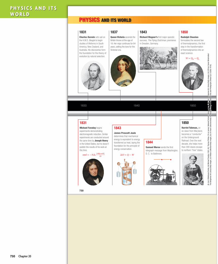
• •
185018401830
1844Samuel Morse sends the first telegraph message from Washington, D. C. to Baltimore.
1843Richard Wagner’s first major operatic success, The Flying Dutchman, premieres in Dresden, Germany.
1837Queen Victoria ascends the British throne at the age of 18. Her reign continues for 64 years, setting the tone for the Victorian era.
1850Rudolph Clausius formulates the second law of thermodynamics, the first step in the transformation of thermodynamics into an exact science.
1831Charles Darwin sets sail on the H.M.S. Beagle to begin studies of lifeforms in South America, New Zealand, and Australia. His discoveries form the foundation for the theory of evolution by natural selection.
1831Michael Faraday begins experiments demonstrating electromagnetic induction. Similar experiments are conducted around the same time by Joseph Henry in the United States, but he doesn’t publish the results of his work at this time.
1843James Prescott Joule determines that mechanical energy is equivalent to energy transferred as heat, laying the foundation for the principle of energy conservation.
1850Harriet Tubman, an ex-slave from Maryland, becomes a “conductor” on the Underground Railroad. Over the next decade, she helps more than 300 slaves escape to northern “free” states.
PHYSICS AND ITS WORLD
(tl),
(bcr
) ©Be
ttman
n/Co
rbis
; (bl
) Mic
hael
Far
aday
(184
1-42
), Th
omas
Phi
llips
. Oil
on c
anva
s. N
atio
nal P
ortra
it Ga
llery
, Lon
don,
UK.
Pho
to ©
Brid
gem
an A
rt Li
brar
y/Ge
tty Im
ages
; (tc
l) ©
Fran
z Xa
vier
Win
terh
alte
r/Th
e Br
idge
man
Art
Libr
ary/
Getty
Imag
es; (
tr) ©
Kean
Col
lect
ion/
Getty
Imag
es; (
tcr)
© K
ean
Colle
ctio
n/Ge
tty Im
ages
;(br)
Libr
ary
of C
ongr
ess,
Prin
ts a
nd P
hoto
grap
hs D
ivis
ion
[LC-
USZ6
2-78
16]
(bl)
Bom
bard
men
t of F
ort S
umte
r, Ch
arle
ston
Har
bor (
19th
cen
tury
), Cu
rrie
r and
Ives
. Mus
eum
of t
he C
ity o
f New
Yor
k. P
hoto
©Sc
ala/
Art R
esou
rce,
NY;
(bc)
Impr
essi
on: S
unris
e, L
e Ha
vre
(187
2), C
laud
e M
onet
. Oil
on c
anva
s, 4
8 x
63 c
m. M
usée
M
arm
otta
n, P
aris
. Pho
to ©
Brid
gem
an-G
iraud
on/A
rt Re
sour
ce, N
Y; (t
l), (b
r) ©
Bettm
ann/
Corb
is; (
tcl)
©Ba
ldw
in H
. War
d &
Kath
ryn
C. W
ard/
Corb
is; (
tcr)
©M
useu
m o
f the
City
of N
ew Y
ork/
Getty
Imag
es; (
tr) ©
Hulto
n Ar
chiv
e/Ge
tty Im
ages
W = Qh - Qc
emf = -N∆ [AB(cosθ)] ________
∆t ∆U = Q - W
730
Untitled-730 730 5/26/2011 9:52:48 AM
P h y s i c s a n d i t s W o r l d
730 Chapter 20

189018801860 1870
1861Benito Juárez is elected president of Mexico. During his administration, the invasion by France is repelled and basic social reforms are implemented.
1861The American Civil War begins at Fort Sumter in Charleston, South Carolina.
1873James Clerk Maxwell completes his Treatise on Electricity and Magnetism. In this work, Maxwell gives Michael Faraday’s discoveries a mathematical framework.
1874The first exhibition of impressionist paintings, including works by Claude Monet, Camille Pissarro, and Pierre-Auguste Renoir, takes place in Paris.
1878The first commercial telephone exchange in the United States begins operation in New Haven, Connecticut.
1884Adventures of Huckleberry Finn, by Samuel L. Clemens (better known as Mark Twain), is published.
1888Heinrich Hertz experimentally demonstrates the existence of electromagnetic waves, which were predicted by James Clerk Maxwell. Oliver Lodge makes the same discovery independently.
1830 – 18901830 – 1890
(tl),
(bcr
) ©Be
ttman
n/Co
rbis
; (bl
) Mic
hael
Far
aday
(184
1-42
), Th
omas
Phi
llips
. Oil
on c
anva
s. N
atio
nal P
ortra
it Ga
llery
, Lon
don,
UK.
Pho
to ©
Brid
gem
an A
rt Li
brar
y/Ge
tty Im
ages
; (tc
l) ©
Fran
z Xa
vier
Win
terh
alte
r/Th
e Br
idge
man
Art
Libr
ary/
Getty
Imag
es; (
tr) ©
Kean
Col
lect
ion/
Getty
Imag
es; (
tcr)
© K
ean
Colle
ctio
n/Ge
tty Im
ages
;(br)
Libr
ary
of C
ongr
ess,
Prin
ts a
nd P
hoto
grap
hs D
ivis
ion
[LC-
USZ6
2-78
16]
(bl)
Bom
bard
men
t of F
ort S
umte
r, Ch
arle
ston
Har
bor (
19th
cen
tury
), Cu
rrie
r and
Ives
. Mus
eum
of t
he C
ity o
f New
Yor
k. P
hoto
©Sc
ala/
Art R
esou
rce,
NY;
(bc)
Impr
essi
on: S
unris
e, L
e Ha
vre
(187
2), C
laud
e M
onet
. Oil
on c
anva
s, 4
8 x
63 c
m. M
usée
M
arm
otta
n, P
aris
. Pho
to ©
Brid
gem
an-G
iraud
on/A
rt Re
sour
ce, N
Y; (t
l), (b
r) ©
Bettm
ann/
Corb
is; (
tcl)
©Ba
ldw
in H
. War
d &
Kath
ryn
C. W
ard/
Corb
is; (
tcr)
©M
useu
m o
f the
City
of N
ew Y
ork/
Getty
Imag
es; (
tr) ©
Hulto
n Ar
chiv
e/Ge
tty Im
ages
c = 1 _____
√ µ0ε0
λ = c _ f
731
Untitled-730 731 5/26/2011 9:52:50 AM
P h y s i c s a n d i t s W o r l d
Electromagnetic Induction 731