1. computational methods - vnrvjiet.ac.in. computational methods 2. applied thermodynamics 3....
TRANSCRIPT
VNR VIGNANA JYOTHI INSTITUTE OF ENGINEERING AND TECHNOLOGY
Department of Automobile Engineering
II B.Tech. II Semester (AE) 2016-17
1. Computational Methods
2. Applied Thermodynamics
3. Automotive Engines and Systems
4. Theory of Machines
5. Basic Electrical and Electronics Engineering
6. Machine drawing
VNR VIGNANA JYOTHI INSTITUTE OF ENGINEERING & TECHNOLOGY
(Autonomous)
DEPARTMENT OF AUTOMOBILE ENGINEERING
Subject : COMPUTATIONAL METHODS
Subject Code : 5BS13
Academic Year : 2016 – 17
Number of working days :
Number of Hours / week :
Total number of periods planned :
Name of the Faculty Member : Dr. G.Padmavathi
1.Scope and objective of the course (one paragraph):
This course includes solution of linear and Transcendental equations, solution of a system
of linear and non-linear large systems by direct and Iterative methods. In Interpolation estimation
of function values and rate of change of functions will be found using various methods of
estimation of functions including highly accurate, interpolation, Spline methods. When
analytical methods of mathematics fail to solve Ordinary Differential Equations of Initial value
and Boundary value Problems type, it may be solved by various Numerical Methods based on
nature of problem. In the last two units, Linear Algebra involving Computational Methods for
solving linear and non-linear problems are done.
Course objectives:
Understand the numerical methods for non linear systems, evaluating definite integrals
and solving Ordinary Differential Equations.
Understand various methods of interpolation and application.
Understand the Echelon form and Normal form of a matrix and its applications in solving
linear system of equations.
Solving system of linear equations using Jacobi and Gauss-Seidal methods.
Learning outcomes:
Student will be able to
Apply the numerical methods to find a root of algebraic and transcendental equations.
Apply the numerical methods to find the solutions of ordinary differential quations.
Find the rank using Echelon form, Normal form and compute eigen values.
Solve linear equations using Jacobi method and Gauss-Seidal method
Text Books :
1. Numerical Methods for science and engineering – Dr B. S. Grewal
REFERENCE BOOKS
1. Advanced Engineering Mathematics -Erwin Kreyszig ,(2002), 8th
Edition, John Wiley and
Sons
2. Elementary Numerical Analysis an Algorithmic Approach-Samuel D.Conte and Carl de
Boor,(2006),3rd
Edition,
Tata McGraw Hill.
3. Numerical Analysis – R.L Burden and J. L. Faires, (2007) Thomson (Indian Edition)
http://www.powershow.com/view/11b458-
MDVmM/Finding_Roots_of_Nonlinear_Equations_powerpoint_ppt_presentation#.Vtw4D
WYyOv8.gmail
Unit: 1 course plan
Lecture Schedule:
Lecture 1: Introduction and importance of numerical methods
Lecture 2: Mathematical Preliminaries
Lecture 3: Methods of solution and Bisection method
Lecture 4: Regula Falsi/ False position method and application
Lecture 5: Iterative methods: fixed point iterative method
Lecture 6: Newton-Raphson method and rate of convergence
Lecture 7: Problems by iterative methods
Lecture 8: Solving problems
Assignment:
1. Find the root of 5 25 with 5th
decimal accuracy.
2. Find the least positive real root of: tan x =1, using Newton’s Raphson method with
6th
decimal accuracy.
3. Write the fixed point algorithm for .0cos xex x and check whether solution
converges.
Unit: 2 Course plan:
Lecture Schedule:
Lecture 1: Introduction and importance of Interpolation &applications
Lecture 2: Un-equally spaced data & Lagrange’s formula
Lecture 4: Different operators and relations among them
Lecture 5: Newton Divided Difference Formula and application
Lecture 6: Equally spaced data and interpolation formulae
Lecture 7: Newton forward and Backward interpolation formulae
Lecture 6: Gauss fwd and bwd difference formulae
Lecture7 : Problems
Lecture8 : Applications

Assignment:
1. Write the best interpolation method and write the advantages and disadvantages of it.
Find the missing values in the following table
x 0 5 10 15 20 25
y 6 10 -- 17 -- 31
3. Prove that 2222 )
2
11(1
4. Find y(25) , given that .40,35,32,24 32282420 yyyy by using Gauss forward
interpolation formula.
5. Using the following table find f(x) as a polynomial in x and using it, estimate function
value at x = 1.
6. Estimate the function at x=0.5 using Gauss formula
x -1 0 1 2 3
y -6 -1 4 12 15
Unit: 3
Numerical Differentiation & Integration, Numerical Solution of Ordinary Differential
Equations :
Lecture Schedule:
Lecture 1: Introduction & importance of Numerical differentiation and Integration
Lecture 2: Differentiation formulae for equ., Uneq. spaced data
Lecture 3: Numerical Integration and Newton-Cotes formula
Lecture 4: Trapezoidal and Simpson’s 1/3, 3/8 Rules
Lecture 5: Quadrature 2, 3 point formula
Lecture 6: Numerical solution of IVP by Taylor’s series
Lecture 7: Picards’ method and problems
Lecture 8: Euler’s and modified Euler’s method
Lecture 9: Runge-kutta method for IVP
Lecture 10: Adams-Bashforth Multistep methods
Lecture 11: Problems
Assignment:
1. Estimate the approximate value of the integral
d2/
0
cos with step size h= π
8 using
⅓ Simpson’s rule and Quadrature 2 , 3 point formulae
2. (a) Using Taylor’s series method find an approximate value of 𝑦1 = xy such that
y(0)=1 at x = 0.1 upto 3rd
decimal accuracy.
(b) Find an approximate solution of 𝑦1 = 𝑦−𝑥
𝑦+𝑥 such that y(0)=1 at x=0.1using 4
th order
Runge-Kutta method.
x -1 0 3 6 7
f(x) 3 -6 39 822 1611

Unit: 4
Matrices Lecture Schedule:
Lecture 1: Elementary Transformations, Rank of matrix,
Lecture 2: Echelon and Normal forms,
Lecture 3: Consistency of linear simultaneous equations
Lecture 4: Homog. And non-homog. systems
Lecture 5: Eigen values and eigen vectors
Lecture 6: and its properties
Lecture 7: Caley – Hamilton theorem (without proof),
Lecture 8: Quadratic forms
Lecture 9: Reduction of quadratic form to canonical form
Lecture 10: By linear(congruent) and orthogonal transforms..
Lecture 11: Problems
Assignment.
Unit: 5
Complex Matrices and Iterative methods
Lecture Schedule:
Lecture 1: Hermitian , skew – Hermitian & Unitary matrices.
Lecture 2: Iterative methods for solving linear system
Lecture 3: Jacobi method
Lecture 4: Gauss-Seidal algorithm
Lecture 5: Power method
Lecture 6: finding largest and smallest eigen values
Lecture 7: Problems
Assignment:
4.Evaluation Scheme:
(a) Assignment Test Weight-age :10 marks, average of 1st and 2
nd Assignments
(b) MID Exams Weight-age : 30 marks with best for 80% and next for 20%
1) I MID forenoon and afternoon
2) II MID forenoon and afternoon

VNR VIGNANA JYOTHI INSTITUTE OF ENGINEERING & TECHNOLOGY
(Autonomous)
DEPARTMENT OF AUTOMOBILE ENGINEERING
Subject : Applied Thermodynamics
Subject Code : 5AE01
Academic Year : 2016 – 17
Number of working days :
Number of Hours / week :
Total number of periods planned :
Name of the Faculty Member : Dr. T. Srinivasa Rao
TEXT BOOKS: 1. Thermal Engineering/ Rathod / TMH
2. Gas Turbines / V. Ganesan / TMH
REFERENCES: 1. Thermal Engineering / R.K.Rajput / Laxmi Publications
2. I. C Engines / Mathur & Sharma / Dhanpath Rai & Sons
2. Thermodynamics & Heat Engines / R.Yadav/ Central Book Depot.
3. Thermal Engineering / P L Ballaney / Khanna Publishers
4. Gas Turbines and Propulsive systems / P Khajuria and S P Dubey / Dhanpat Rai & Sons
Course Plan:
S.No. Topic Name Number of
Periods
Cumulative
Periods
1 INTRODUCTION 1 1
UNIT-I
2 Introduction & Classification of Boilers 1 2
3 Working Principles of Fire Tube and Water Tube
Boilers
1 3
4 Babcock and Wilcox 1 4
5 Lamont Boiler 1 5
6 Boiler draught 2 7
7 Performance of boilers 2 9
8 Purpose and types of condensers 2 11
9 Efficiency of condenser, Edward Air Pump 2 13
UNIT-II
10 Functions of nozzle, applications & types 1 14
11 Flow through nozzles, Thermodynamic analysis 2 16
12 Ideal and actual expansion in nozzle 1 17
13 Condition for maximum discharge, Critical pressure
ratio.
2 19
14 Steam Turbines Classification 1 20
15 Impulse turbine Velocity diagram 2 22

16 Effect of friction, Power developed 2 24
17 Diagram efficiency, Condition for maximum
efficiency
2 26
18 Methods to reduce rotor speed. 1 27
19 Reaction Turbine: Mechanical details – principle of
operation
1 28
20 Thermodynamic analysis of a stage, Degree of
reaction, velocity diagram
2 30
21 Parson’s reaction turbine, condition for maximum
efficiency.
1 31
UNIT-III
22 Compressors : Classification 1 32
23 fan, Blower and compressor 1 33
24 Roots blower, Vane blower 1 34
25 Lysholm compressor –working principles. 1 35
26 Reciprocating Compressors: Principle of operation 1 36
27 Work required, Isothermal efficiency, volumetric
efficiency
2 38
28 effect of clearance 1 39
29 Multi Stage compression 1 40
30 minimum work condition for stage compression 2 42
UNIT-IV
31 Centrifugal Compressors: Mechanical details and
principle of operation
1 43
32 Velocity and pressure variation, . Energy transfer 1 44
33 Impeller blade shape-losses, slip factor, power input
factor, pressure co-efficient and adiabatic co-efficient
2 46
34 velocity diagrams, power requirement to run the
compressor
2 48
35 Axial flow compressors- principle of operation,
velocity triangles and energy transfer per stage
2 50
36
Degree of reaction, work done factor, Isentropic
efficiency
1 51
37 Pressure rise calculations, Polytrophic efficiency 1 52
UNIT-V
38 Classification of Gas Turbine plants 1 53
39 Essential components, parameters of performance 1 54
40 Actual cycle, regeneration, inter cooling and
reheating.
2 56
41 Classification of Jet propulsion engines, Working
principles schematic diagram and representation on
T- s diagram.
2 58
31 Needs and demands met by Turbo Jet Engines 1 59
32 Application, working principle, Classification,
Propellant type.
2 61

Submission Dates for Assignments:
S. No. Assignment Topic Last date for Submission
1 1 to 21 11-02-2016
2 22 to 32 25-04-2016
UNIT I
Steam Generators: Introduction, Classification of Boilers, Working Principles of Fire Tube and
Water Tube Boilers, Low Pressure boilers, High Pressure Boilers, Babcock and Wilcox, Lamont
Boiler, Boiler draught and performance of boilers, Equivalent evaporation.
Steam Condensors: Introduction, purpose and types of condensers, Efficiency of condenser,
Edward Air Pump.
Learning objectives : after successful completion of unit – I the student will be able to
1. Understand the differences between various boilers
2. Select the boiler based on the application.
3. Perform the draught and heat balance calculations.
4. Design the steam condenser.
UNIT – II
Steam Nozzles : Functions of nozzle, applications, types, flow through nozzles, Thermodynamic
analysis, assumptions, velocity of nozzle at exit, Ideal and actual expansion in nozzle, velocity
co-efficient, condition for maximum discharge, Critical pressure ratio.
Steam Turbines: Classification – Impulse turbine, Mechanical details, Velocity diagram, Effect
of friction, Power developed, axial thrust, diagram efficiency, Condition for maximum
efficiency. Methods to reduce rotor speed.
Reaction Turbine: Mechanical details – principle of operation, Thermodynamic analysis of a
stage, Degree of reaction, velocity diagram, parson’s reaction turbine, condition for maximum
efficiency.
Learning objectives: after successful completion of unit – II the student will be able to
1. Choose the geometry of the nozzle for the given conditions.
2. Calculate the maximum mass flow through given nozzle.
3. Design the various components of the steam turbines.
UNIT – III
Compressors : Classification – Power producing and power absorbing machines, fan, Blower
and compressor, Roots blower, Vane blower, Sealed compressor, Lysholm compressor –
working principles.
Reciprocating Compressors: Principle of operation, work required, Isothermal efficiency,
volumetric efficiency and effect of clearance, Multi Stage compression, under cooling, saving of
work, minimum work condition for stage compression.
Learning objectives: after successful completion of unit – III the student will be able to
1. Understand the working principles of different types of compressors.
2. Find the optimum parameters for reciprocating compressors.
3. Appreciate the difference between fans, blowers and compressors.
4. Select the type of compressor for particular application.
UNIT – IV
Centrifugal Compressors: Mechanical details and principle of operation, velocity and pressure
variation. Energy transfer, Impeller blade shape-losses, slip factor, power input factor, pressure
co-efficient and adiabatic co-efficient, velocity diagrams, power requirement to run the
compressor.
Axial flow compressors: Mechanical details and principle of operation, velocity triangles and
energy transfer per stage degree of reaction, work done factor, Isentropic efficiency, Pressure rise
calculations,
Polytrophic efficiency
Learning objectives : after successful completion of unit – IV, the student will be able to
1. Understand the applications and working principles of centrifugal compressors.
2. Draw velocity diagrams and calculate the different performance parameters.
3. Select the type of compressor for particular application.
UNIT – V
Gas Turbines: Classification of Gas Turbine plants, Ideal cycle, essential components,
parameters of performance, actual cycle, regeneration, inter cooling and reheating.
Jet Propulsion and Rockets: Classification of Jet propulsion engines, Principle of operation,
working principles with schematic diagram and representation on T- s diagram. Needs and
demands met by Turbo Jet Engines, Rockets, Application, working principle, Classification,
Propellant type.
Learning objectives : after successful completion of unit – V the student will be able to
1. Justify the importance of each component in gas turbine power plant.
2. Understand the principles of jet propulsion.
3. Identify essential components of jet propulsion.
4. Do calculations on performance of jet propulsion.
VNR VIGNANA JYOTHI INSTITUTE OF ENGINEERING & TECHNOLOGY
(Autonomous)
DEPARTMENT OF AUTOMOBILE ENGINEERING
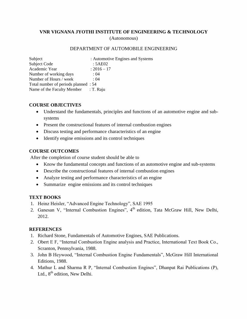
Subject : Automotive Engines and Systems
Subject Code : 5AE02
Academic Year : 2016 – 17
Number of working days : 04
Number of Hours / week : 04
Total number of periods planned : 54
Name of the Faculty Member : T. Raju
COURSE OBJECTIVES
Understand the fundamentals, principles and functions of an automotive engine and sub-
systems
Present the constructional features of internal combustion engines
Discuss testing and performance characteristics of an engine
Identify engine emissions and its control techniques
COURSE OUTCOMES
After the completion of course student should be able to
Know the fundamental concepts and functions of an automotive engine and sub-systems
Describe the constructional features of internal combustion engines
Analyze testing and performance characteristics of an engine
Summarize engine emissions and its control techniques
TEXT BOOKS
1. Heinz Heisler, “Advanced Engine Technology”, SAE 1995
2. Ganesan V, “Internal Combustion Engines”, 4th
edition, Tata McGraw Hill, New Delhi,
2012.
REFERENCES
1. Richard Stone, Fundamentals of Automotive Engines, SAE Publications.
2. Obert E F, “Internal Combustion Engine analysis and Practice, International Text Book Co.,
Scranton, Pennsylvania, 1988.
3. John B Heywood, “Internal Combustion Engine Fundamentals”, McGraw Hill International
Editions, 1988.
4. Mathur L and Sharma R P, “Internal Combustion Engines”, Dhanpat Rai Publications (P),
Ltd., 8th
edition, New Delhi.
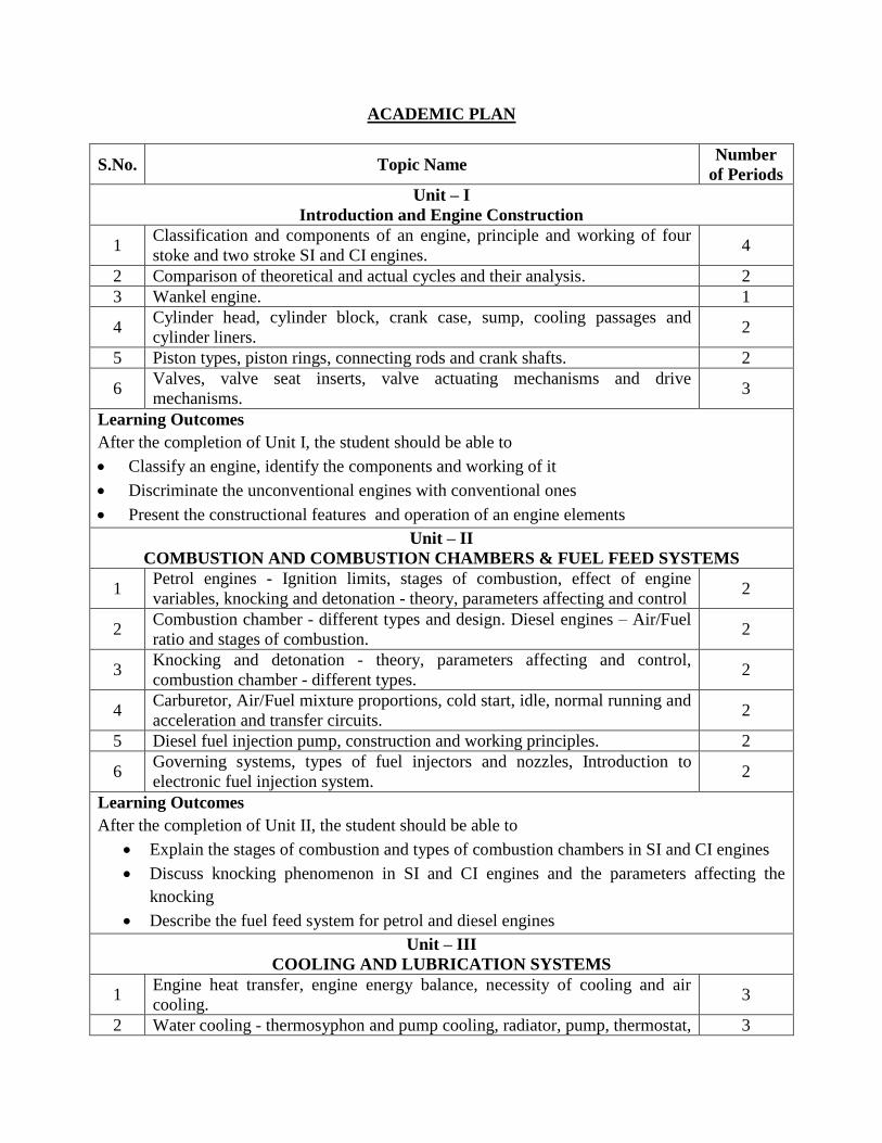
ACADEMIC PLAN
S.No. Topic Name Number
of Periods
Unit – I
Introduction and Engine Construction
1 Classification and components of an engine, principle and working of four
stoke and two stroke SI and CI engines. 4
2 Comparison of theoretical and actual cycles and their analysis. 2
3 Wankel engine. 1
4 Cylinder head, cylinder block, crank case, sump, cooling passages and
cylinder liners. 2
5 Piston types, piston rings, connecting rods and crank shafts. 2
6 Valves, valve seat inserts, valve actuating mechanisms and drive
mechanisms. 3
Learning Outcomes
After the completion of Unit I, the student should be able to
Classify an engine, identify the components and working of it
Discriminate the unconventional engines with conventional ones
Present the constructional features and operation of an engine elements
Unit – II
COMBUSTION AND COMBUSTION CHAMBERS & FUEL FEED SYSTEMS
1 Petrol engines - Ignition limits, stages of combustion, effect of engine
variables, knocking and detonation - theory, parameters affecting and control 2
2 Combustion chamber - different types and design. Diesel engines – Air/Fuel
ratio and stages of combustion. 2
3 Knocking and detonation - theory, parameters affecting and control,
combustion chamber - different types. 2
4 Carburetor, Air/Fuel mixture proportions, cold start, idle, normal running and
acceleration and transfer circuits. 2
5 Diesel fuel injection pump, construction and working principles. 2
6 Governing systems, types of fuel injectors and nozzles, Introduction to
electronic fuel injection system. 2
Learning Outcomes
After the completion of Unit II, the student should be able to
Explain the stages of combustion and types of combustion chambers in SI and CI engines
Discuss knocking phenomenon in SI and CI engines and the parameters affecting the
knocking
Describe the fuel feed system for petrol and diesel engines
Unit – III
COOLING AND LUBRICATION SYSTEMS
1 Engine heat transfer, engine energy balance, necessity of cooling and air
cooling. 3
2 Water cooling - thermosyphon and pump cooling, radiator, pump, thermostat, 3

antifreeze solution and radiator fan.
3 Lubrication Systems – Mist, splash, forced and dry sump lubrication. 2
4 Wet sump lubrication, oil filters and oil pumps. 2
Learning Outcomes
After the completion of Unit III, the student should be able to
Discuss cooling requirements, types of cooling systems, parts and coolants
Explain the lubrication system types and elements involved in it.
UNIT IV- SUPERCHARGING AND TURBOCHARGING
1. Necessity of supercharging, mechanical supercharging and turbocharging. 2
2. compressors and turbines for supercharging 2
3. Degree of supercharging, methods of supercharging and efficiency of
supercharged engine.
2
Learning Outcomes
After the completion of Unit III, the student should be able to
Describe the methods of supercharging and turbocharging and degree of supercharging
Unit – V
ENGINE TESTING AND PERFORMANCE & ENGINE EMISSION AND CONTROL
1 Indicated power, brake power, engine torque, mechanical efficiency and air
standard efficiency 2
2 Brake thermal efficiency, indicated thermal efficiency, relative efficiency and
volumetric efficiency. 2
3 Heat balance sheet and exhaust gas analyzer. 2
4 Sources of emissions, unburnt hydrocarbons (HC), oxides of nitrogen (NOX)
and carbon monoxide (CO) in SI engines. 2
5 Catalytic converters, unburnt hydrocarbons (HC), oxides of nitrogen (NOX)
and particulate matter (PM) in CI engines. 2
6 Exhaust gas recirculation. 2
Learning Outcomes
After the completion of Unit V, the student should be able to
Illustrate the performance characteristics and different efficiencies of an engine
Identify sources of engine emissions from SI and CI engines
Explain catalytic converter and exhaust gas recirculation
Cumulative Periods 54
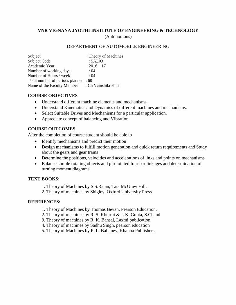
VNR VIGNANA JYOTHI INSTITUTE OF ENGINEERING & TECHNOLOGY
(Autonomous)
DEPARTMENT OF AUTOMOBILE ENGINEERING
Subject : Theory of Machines
Subject Code : 5AE03
Academic Year : 2016 – 17
Number of working days : 04
Number of Hours / week : 04
Total number of periods planned : 60
Name of the Faculty Member : Ch Vamshikrishna
COURSE OBJECTIVES
Understand different machine elements and mechanisms.
Understand Kinematics and Dynamics of different machines and mechanisms.
Select Suitable Drives and Mechanisms for a particular application.
Appreciate concept of balancing and Vibration.
COURSE OUTCOMES
After the completion of course student should be able to
Identify mechanisms and predict their motion
Design mechanisms to fulfill motion generation and quick return requirements and Study
about the gears and gear trains
Determine the positions, velocities and accelerations of links and points on mechanisms
Balance simple rotating objects and pin-jointed four bar linkages and determination of
turning moment diagrams.
TEXT BOOKS:
1. Theory of Machines by S.S.Ratan, Tata McGraw Hill.
2. Theory of machines by Shigley, Oxford University Press
REFERENCES:
1. Theory of Machines by Thomas Bevan, Pearson Education.
2. Theory of machines by R. S. Khurmi & J. K. Gupta, S.Chand
3. Theory of machines by R. K. Bansal, Laxmi publication
4. Theory of machines by Sadhu Singh, pearson education
5. Theory of Machines by P. L. Ballaney, Khanna Publishers

ACADEMIC PLAN
S.No. Topic Name Number
of Periods
UNIT-I
MECHANISMS AND MACHINES, PLANE MOTION OF BODY
1 Introduction, Mechanism and Machine, Rigid and Resistant Bodies, Link,
Kinematic Pair, Degrees of Freedom 2
2 Classification of Kinematic Pairs, Kinematic Chain Linkage, Mechanism and
Structure, 2
3 Mobility of Mechanisms, The Four-Bar Chain 2
4 The Slider-Crank Chain & Double Slider-Crank Chain mechanisms 2
5 Inversions of these mechanisms, Mechanical Advantage 2
6 Instantaneous center of rotation, centrode - relative motion between two
bodies-Three centers in line theorem 2
Learning Outcomes
After the completion of Unit I, the student should be able to
Identify mechanisms and predict their motion
Determine the kinematic chain and mobility
Perform the kinematic analysis of a given mechanism
Unit – II
KINEMATICS, ANALYSIS OF MECHANISMS
1 Velocity and acceleration-motion of link in machine 2
2 Determination of velocity and acceleration diagrams-graphical method 2
3 Application of relative velocity method- four bar chain 2
4 Analysis of slider crank chain for displacement, velocity and acceleration of
slider- acceleration diagram for a given mechanism 2
5 Klein’s construction, Coriolis acceleration, determination of Coriolis
component of acceleration 2
6 dynamic analysis of slider-crank mechanism 2
Learning Outcomes
After the completion of Unit II, the student should be able to
Understanding of the concepts of displacement, velocity and acceleration as vectors and
how to determine them
Discuss Klein’s construction, Coriolis acceleration and determine acceleration for a given
mechanism
Analyze dynamics of given mechanism
Unit – III
CAMS
1 Definition of cam and followers-their uses-types of followers and cams-
terminology 2
2 Types of follower motion-uniform velocity-simple harmonic motion and
uniform acceleration 2
3 Maximum velocity and acceleration during outward and return strokes in the
above three cases 2

4 Analysis of motion of followers: roller follower- circular cam with straight, 2
5 Concave and convex flanks. 2
6 Problems 2
Learning Outcomes
After the completion of Unit III, the student should be able to
Describe the various combinations of cams and follower
Design the cam profile for give conditions
Determine velocity and acceleration at various conditions
Unit – IV HIGHER PAIRS, GEAR TRAINS
1 Friction wheels and toothed gears-types-law of gearing, condition for
constant velocity ratio for transmission of motion 2
2 Forms of teeth- Cycloidal and Involute profiles. Velocity of sliding-
phenomena of interference-methods of interference 2
3 condition for minimum number of teeth to avoid interference, expression for
arc of contact and path of contact.. 2
4 Introduction-train value-types-simple and reverted wheel trains 2
5 epicyclic gear train, methods of finding train value or velocity ratio-selection
of gear box differential gear for an automobile. 2
6 Problems 2
Learning Outcomes
After the completion of Unit IV, the student should be able to
Discuss friction and toothed wheel, forms of teeth
Explain the gear train system.
Design the gear train system for their requirement
Unit – V
TURNING MOMENT DIAGRAMS, GYROSCOPE, BALANCING
1 Inertia torque-angular velocity and acceleration of connecting rod, crank
effort and torque diagrams 2
2 Angular Velocity, Angular Acceleration, Gyroscopic Torque, Gyroscopic
Effect on Naval Ships 2
3 Stability of an Automobile, Stability of a Two-Wheel Vehicle 2
4 Introduction, Static Balancing, Dynamic Balancing 2
5 Transference of a Force from One Plane to Another, Balancing of Several
Masses in Different Planes 2
6 Transference of a Force from One Plane to Another, Balancing of Several
Masses in Different Planes 2
Learning Outcomes
After the completion of Unit V, the student should be able to
Draw the turning movement diagram for flywheel
Gyroscopic effect on naval ship, 4-wheel drive and 2-wheel drive
Balance the un balanced rotating and reciprocating masses in automotive
Cumulative Periods 60

VNR VIGNANA JYOTHI INSTITUTE OF ENGINEERING & TECHNOLOGY
(Autonomous)
DEPARTMENT OF AUTOMOBILE ENGINEERING
Subject : BASIC ELECTRICAL AND ELECTRONICS ENGINEERING
Subject Code : 5EE23
Academic Year : 2016 – 17
Number of working days :
Number of Hours / week :
Total number of periods planned :
Name of the Faculty Member : R.Sireesha
UNIT-I:
syllabus
ELECTRICAL CIRCUITS: Circuit Concept R-L-C parameters-Ohm’s law - Kirchhoff’s laws
- Series - Parallel resistive networks - Star/delta transformations.
AC Circuits : Average value, RMS value, form factor of sinusoidal function, R-L, R-C and R-L-
C circuits- Concept of Power factor, Real and reactive powers simple problems.
Learning Objectives On the conclusion of the Unit - I , the student must be able to
Identify the difference between Active & Passive elements
Explain the properties of R, L, C parameters.
Solve problems based on the network reduction technique
Solve problems using circuit Analysis
Lecture plan: 13hours Lecture1: Introduction to Electrical Circuits Lecture2: Definition of network, circuit & Network elements classifications Lecture3: RLC parameters Lecture4: Series, parallel resistive network an problems Lecture5: KVL discussion and problem Lecture6: KCL discussion and problem Lecture7: Concept of network reduction technique & problems for various combinations Lecture8: Star transformation and problem Lecture9: Delta transformation and problem Lecture10: RM.S, Average values of sinusoidal waveform
Lecture11: Form factor and peak factor for sinusoidal wave form
Lecture12: Response of R-L,R-C,R-L-C circuits with sinusoidal excitation Lecture13: concept of power factor, Real, Reactive power
Tutorial
1. Define Kirchhoff’s laws
2. Describe network sources, resistive, inductive and capacitive networks and series-parallel
networks.
3. Explain Star and Delta transformation with an example?
4. Explain KVL and KCL with an example?

5 An alternating current is expressed as i=14.14sin314t. Determine: a) rms current b) frequency
c) instantaneous current when t = 0.02ms.
6. Give an explanation of analysis of ac circuits with single basic network element taking an
example.
Assignment
1. Define Network & Network elements. 2. Classify network elements based on their properties. 3. Calculate the equivalent resistance for any one type of network. 4. Explain about Active, Reactive and apparent powers. Give expression for the above. 5. Define RMS , average value and form factor of an alternating quantity.
UNIT-II:
Syllabus
DC MACHINES: Principle of operation of DC Generator – emf equation - types – Principle of
operation of DC Motor - DC motor types –torque equation – Three point starter -Swinburne’s
test, applications.
TRANSFORMERS: Principle of operation of single phase transformer–emf equation– losses–
OC and SC tests - efficiency and regulation
Learning Objectives
On the conclusion of the Unit – II, the student must be able to
Explain the principle of operation of DC Generator with types Explain the principle of operation of DC Motor with types Identify the difference between generator and motor Explain the principle of operation of single phase transformer
Lecture Plan : 13 hours
Lecture1&2 : Working principle of DC Generator
Lecture3 : Derivation of EMF Equation with problems Lecture4 : Types of DC generator Lecture 5&6 : Working principle of DC Motor Lecture7 : Derivation of Torque Equation with problems Lecture8 : Maximum Power Transfer Theorem Lecture9 : Three point starter Lecture10 : Swinburne’s test description on DC Motor Lecture11 : Principle of operation of single phase transformer Lecture12 : Derivation of EMF Equation with problems Lecture13 : Efficiency and regulation of single phase transformer
Tutorial
1. Explain the principle of operation of dc motor. 2. A shunt generator delivers 50 kW at 250 V and runs at 400 rpm. The armature and field
resistances are 0.02 Ω and 50 Ω respectively. Calculate the speed of the machine running as
a shunt motor and taking 50 kW input at 250 V. Allow 1 V per brush for contact drop.
3. What are the losses in a transformer and how they vary with load? Deduce a condition for
maximum efficiency.
4. Derive the emf equation of dc generator.
5. Derive the torque equation of dc motor
6. Distingish between dc generator and dc motor.
7. List out Various types of dc generator and dc motor with operation.
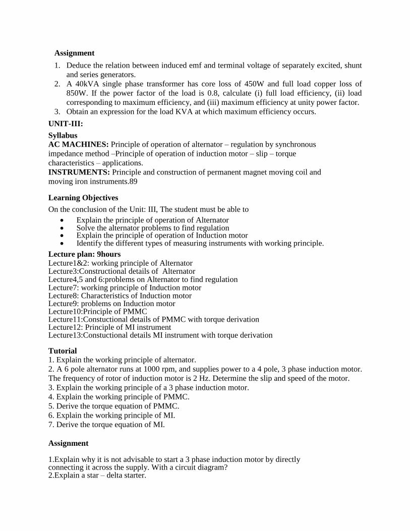
Assignment
1. Deduce the relation between induced emf and terminal voltage of separately excited, shunt
and series generators.
2. A 40kVA single phase transformer has core loss of 450W and full load copper loss of
850W. If the power factor of the load is 0.8, calculate (i) full load efficiency, (ii) load
corresponding to maximum efficiency, and (iii) maximum efficiency at unity power factor.
3. Obtain an expression for the load KVA at which maximum efficiency occurs.
UNIT-III:
Syllabus AC MACHINES: Principle of operation of alternator – regulation by synchronous
impedance method –Principle of operation of induction motor – slip – torque
characteristics – applications.
INSTRUMENTS: Principle and construction of permanent magnet moving coil and
moving iron instruments.89
Learning Objectives
On the conclusion of the Unit: III, The student must be able to
Explain the principle of operation of Alternator Solve the alternator problems to find regulation Explain the principle of operation of Induction motor Identify the different types of measuring instruments with working principle.
Lecture plan: 9hours Lecture1&2: working principle of Alternator Lecture3:Constructional details of Alternator Lecture4,5 and 6:problems on Alternator to find regulation Lecture7: working principle of Induction motor Lecture8: Characteristics of Induction motor Lecture9: problems on Induction motor Lecture10:Principle of PMMC Lecture11:Constuctional details of PMMC with torque derivation Lecture12: Principle of MI instrument Lecture13:Constuctional details MI instrument with torque derivation Tutorial 1. Explain the working principle of alternator.
2. A 6 pole alternator runs at 1000 rpm, and supplies power to a 4 pole, 3 phase induction motor.
The frequency of rotor of induction motor is 2 Hz. Determine the slip and speed of the motor.
3. Explain the working principle of a 3 phase induction motor.
4. Explain the working principle of PMMC.
5. Derive the torque equation of PMMC.
6. Explain the working principle of MI.
7. Derive the torque equation of MI.
Assignment
1.Explain why it is not advisable to start a 3 phase induction motor by directly connecting it across the supply. With a circuit diagram? 2.Explain a star – delta starter.

UNIT-IV:
Syllabus
Diode and its characetistics:
Diode equation, Symbol and volt ampere characteristics. Diode applications Half-wave
rectifier, Full-wave rectifier and bridge rectifier(simple problems).
Learning objectives
At the end of completion of all learning activities the student is able to
Explain pn junction diode
Explain forward bias and reverse bias
Explain the V-I characteristics of forward biased pn junction diode
Explain the V-I characteristics of reverse biased pn junction diode
Define static resistance, dynamic resistance and bulk resistance of a diode.
Define reverse saturation current and reverse breakdown voltage of a diode.
Describe current equation of diode.
Explain the current components of a diode
Define transition capacitance and diffusion capacitance of a diode.
Distinguish the features of Si and Ge diodes
Explain the function of rectifier
Explain half wave rectifier and full wave rectifier
Explain the advantages of full wave rectifier over half wave rectifier
Explain the advantage of bridge rectifier
Define and derive Ripple factor, % regulation, efficiency of HWR
Define and derive Ripple factor, % regulation, efficiency of FWR
Lecture plan: 11Hrs
Lecture1: introduction
Lecture2: pn-junction diode FB, RB Characteristics & junction Potential
Lecture3: Diode parameters, specifications, equivalent circuits
Lecture4: Diode current components, current equation
Lecture5: Introduction to Rectifiers, Half wave rectifier circuits, operation
Lecture6: Full wave and bridge rectifier, circuits, operation
Lecture7: Performance Parameters (Regulation, Ripple factor, efficiency etc.) Derivations
Tutorial
1. For a silicon diode with reverse saturation current of 0.2 μA, calculate the dynamic forward
and reverse resistance at a voltage of 0.72 V and -0.72 V respectively, applied across the
diode, at room temperature of 270 C.
2. Afull wave rectifier is operated from 50Hz supply with 120Vrms.It is connected to a load
drawing 50 mA and using 100μF capacitor filter. Calculate the dc output voltage and the rms
value of ripple voltage. Also calculate the ripple factor.
3. A full wave bridge rectifier is using LC filter. The peak value of the transformer secondary
voltage is 162 V.The LC filter components are L= 1000mH with 100 Ω resistance and C=50
μF .The load resistance is 1K Ω Calculate the dc filter output voltage and ripple factor.
4. Calculate the ripple factor for a π type filter ,employing 10Hchoke and two equal capacitors
16 μF each and fed from a full wave rectifier and 50Hzs main.

Assignment
1. What is the ratio of current for a forward bias of 0.08V to the current for the same
magnitude of reverse bias for the Germanium diode.
2. The transition capacitance of an abrupt junction diode is 30pf at 8V Determine
the value of Capacitance for an increase in the bias voltage of 2 V.
3. Find the value of dc resistance and ac resistance of a Ge junction diode at 25 0C, I0 =
10μA and applied voltage is 0.1 V.
4. Calculate the Dynamic forward and reverse resistance of a PN junction diode when the
applied Voltage is 0.2 V, I0 =2 μA and T= 25 0C. Consider Ge diode.
5. A Half wave rectifier circuit feeds a resistive load of 10KΩ through a power transformer
having a step down turns ratio of 8:1 and operated from 230V,50Hzs ac mains supply.
Assume the forward resistance of a diode to be 40Ω and transformer secondary winding
resistance as 12Ω. Calculate the maximum, RMS,and average values of current ,DC output
voltage and power ,efficiency of rectification and ripple factor.
6. A bridge rectifier uses four identical diodes having forward resistance of 5 Ω each.
Transformer secondary resistance is 5 Ω and secondary voltage is 30V
(R.M.S).Determine the D.C output voltage for Idc= 200mA.and the value of output ripple
voltage
7. A full wave rectifier circuit is fed from a transformer having centre tapped secondary
winding .The rms voltage from either end of secondary tap to centre is 20V.If the diode
forward resistance is 3Ω and that of secondary is 5Ω,for a load of 1KΩ,calculate
a) power delivered to load
b) % regulation at full load
c) efficiency at fullload
d) TUF of secondary.
8. A full wave single phase rectifier makes use of two diodes, the internal forward resistance
of each can be considered as 30Ω.The load resistance is 1KΩ.The transformer secondary
voltage is 200-0-200Vrms. Calculate
a) The dc load current
b) The dc output voltage
c) PIV of diode.
UNIT V:
Syllabus
Transistors
pnp and npn junction transistor. Transistor as an amplifier, SCR Characteristics and applications.
Cathode Ray Oscilloscope:
Principles of CRT, Deflection, sensitivity, Electrostatic and magnetic deflection, applications of
CRO, voltage, current and frequency measurements.
Learning objectives
At the end of completion of all learning activities the student is able to
Explain the principle of operation of transistor (pnp and npn)
Explain the basic techniques used for the construction of transistor (grown type,micro
alloy type, electrochemically etched type, diffusion type, epitaxial growth type)
Draw the symbols and different configurations of transistor
Draw and explain the input and out put characteristics of common emitter configuration.
Draw and explain the input and out put characteristics of common base configuration
Draw and explain the input and out put characteristics of common collector configuration
Identify active ,cutoff and saturation regions on out put characteristics
Derive expression for collector current in CE configuration.
Explain the principle of operation CRT.
Explain the Electrostatic and magnetic deflection.
Explain the voltage, current and frequency measurements.
Lecture plan:16Hrs
Lecture1 : Introduction to Bipolar junction transistor, Transistor operation (NPN&PNP)
Configurations
Lecture2 : Common base configuration characteristics, early effect
Lecture3 : Common emitter configuration characteristics,
Lecture4 : Common collector configuration characteristics
Lecture7 : Transistor as an amplifier
Lecture8: Problems on transistor currents
Lecture9: principle of operation CRT
Lecture10: Deflection, sensitivity
Lecture11: Electrostatic and magnetic deflection
Lecture12: applications of CRO
Lecture13: voltage measurements
Lecture 14: current measurements
Lecture 15: frequency measurements
Tutorial.
1. In a certain transistor 99.6% of the carriers injected into the base cross the collector-base
junction. If the leakage current is 5 µA and the collector current is 200mA,calculate (i)
the value of αdc (ii) the emitter current
2. Calculate the values of collector current and the base current for a transistor with αdc=
0.99 and ICBO= 10 μA. The emitter current is measured as 8 mA.
3. An npn transistor of β = 50 is used in common emitter circuit with Vcc=10V and Rc =
2KΩ is obtained by connecting 100KΩ resistance from collector to base. Find the
quiescent point and stability factors.
4. Explain the principle of operation CRT.
5. Explain the Electrostatic and magnetic deflection.
Assignment
1. Calculate the values of collector current and emitter current for a transistor with αdc= 0.99
and ICBO= 5 μA. The base current is measured as 20 μA.
2. The reverse leakage current of a transistor when connected in CB configuration is 0.2 μA
while it is 18 μA when the same transistor is connected in CE configuration. Calculate
αdc and βdc.
3. CalculateRi,Ai=Il/Is,Av,Avs=Vo/Vs,Rofortheckt,R1=10K,Rs=1K,R2=10K,RL=20K.
For the CB ckt the transistor parameters are hib=22ohms,hfb=-0.98,hob=0.49microA
4. Explain the voltage, current and frequency measurements.

VNR VIGNANA JYOTHI INSTITUTE OF ENGINEERING & TECHNOLOGY
(Autonomous)
DEPARTMENT OF AUTOMOBILE ENGINEERING
Subject : Machine drawing
Subject Code : 5ME57
Academic Year : 2016 – 17
Number of working days : 32
Number of Hours / week : 06
Total number of periods planned : 70
Name of the Faculty Member : R. Ramu
Machine drawing conventions - 1 hr
Need for drawing conventions – Introduction to IS conventions - 3 hrs
a) Conventional representation of materials, common machine elements and parts such as
screws, nuts, bolts, keys, gears, webs and ribs.-6 hrs
b) Types of sections – selection of section planes and drawing of sections and auxiliary
sectional views. – 3 hrs
c) Parts not usually sectioned.-3 hrs
d) Methods of dimensioning, general rules for sizes, and placement of dimensions for holes,
centers, and curved and tapered features.- 3 hrs
e) Title boxes, their size, location, and other details - common abbreviations and their liberal
usage-3 hrs
f) Types of drawings – working drawings for machine parts.-3 hrs
DRAWING OF MACHINE ELEMENTS AND SIMPLE PARTS- 3 hrs
Selection of orthogonal views and additional views for the following machine elements and parts
with every drawing proportion.
a) Popular forms of screw threads, bolts, nuts, stud bolts. - 3 hrs
b) Keys, cottered joints, and knuckle joint.- 3 hrs + 3 hrs
c) Riveted joints for plates.- 3 hrs
d) Shaft coupling and spigot joint.- 3 hrs
e) Journal, pivot, and collar bearings.- 3 hrs
ASSEMBLY DRAWINGS
Assembly drawings using conventions and easy drawing proportions- 6 hrs
a) Engine parts – stuffing boxes- 3 hrs,
b) eccentrics- 3 hrs,
c) I.C. engine connecting rod – 3 hrs
d) piston assembly- 3 hrs
e) Other parts - screws jacks- 3 hrs
f) Machine vices,- 3 hrs
g) Tailstock.- 3 hrs
NOTE
1. To adopt first angle of projection.
2. The student should be able to provide working drawings of actual parts.
TEXT BOOK:
1. Machine Drawing by K. L. Narayana, P. Kannaiah and K. Venkata Reddy;
Publisher:New Age/ Publishers.
REFERENCES:
1. Machine Drawing by Siddheswar, Kannaiah and Sastry.
2. Machine Drawing by N. D. Bhat.