1 combinational logic chapter 4. 2 §agenda § combinational logic l design procedure l adders,...
TRANSCRIPT
1
Combinational Logic
Chapter 4
2
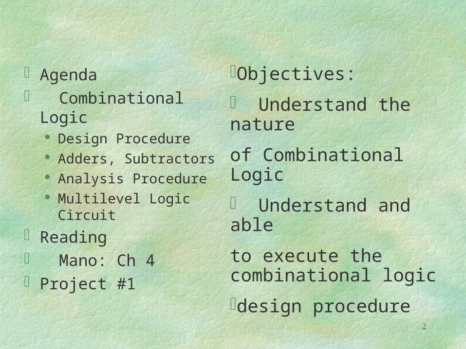
Agenda Combinational Logic
Design Procedure Adders, Subtractors Analysis Procedure Multilevel Logic Circuit
Reading Mano: Ch 4Project #1
Objectives:
Understand the nature
of Combinational Logic
Understand and able
to execute the combinational logic
design procedure
3
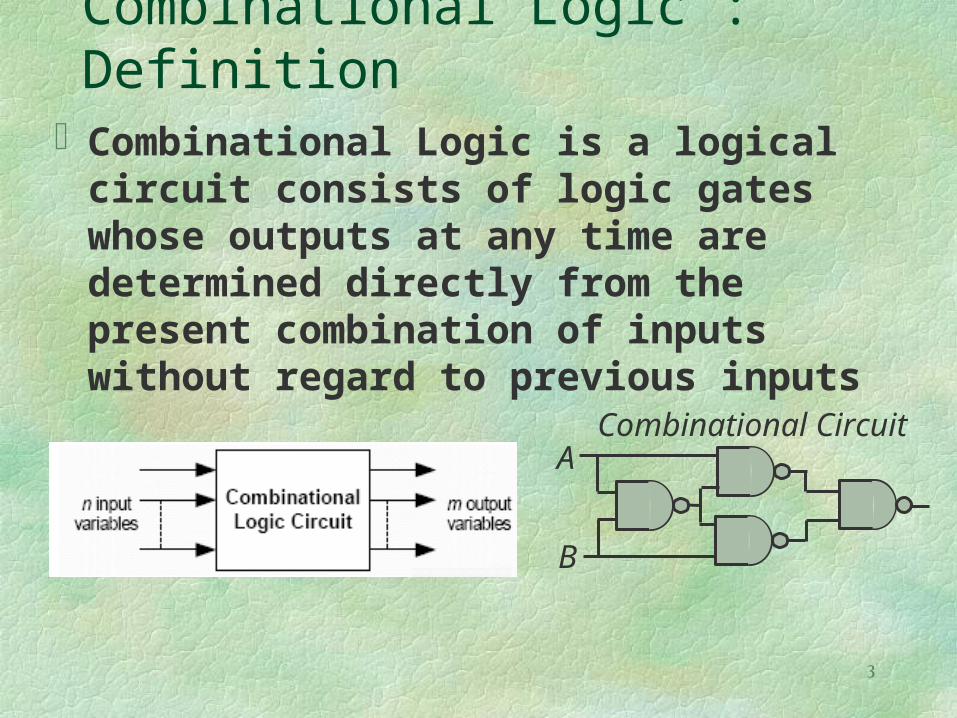
Combinational Logic : DefinitionCombinational Logic is a logical
circuit consists of logic gates whose outputs at any time are determined directly from the present combination of inputs without regard to previous inputs
Combinational CircuitA
B

4
Analysis Procedure:
F2=AB+AC+BCT1=A+B+C
T2=ABCand
T3=F2' T1F1=T3+T2Therefore,
F1=T3+T2= F2' T1 + ABC =( AB+AC+BC)'(A+B+C) +
ABC=(A'+B')(A'+C')(B'+C')(A+B+C)+ABC
==A'BC'+A'B'C+AB'C'+ABC

5
Design Procedure:
1. Define the problem2. Define the input/output variables3. Truth table of the relationships4. Simplify Boolean functions5. Draw the logic diagram
Constraints:1. Min No. of gates2. Minimum number of inputs to a gate3. Min Propagation time4. Min no. of interconnections
6
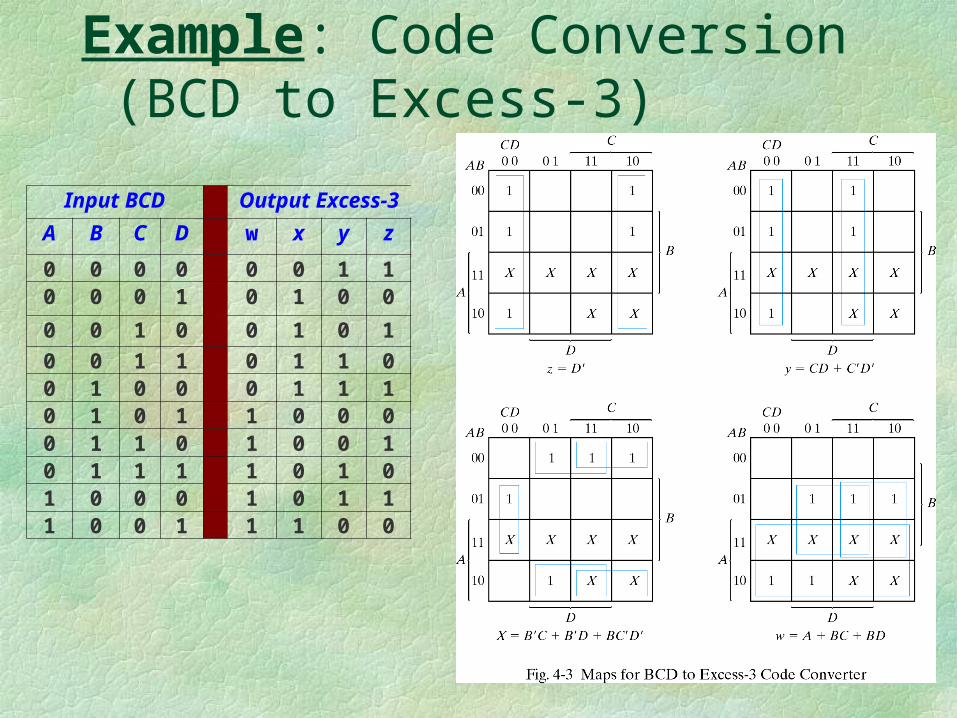
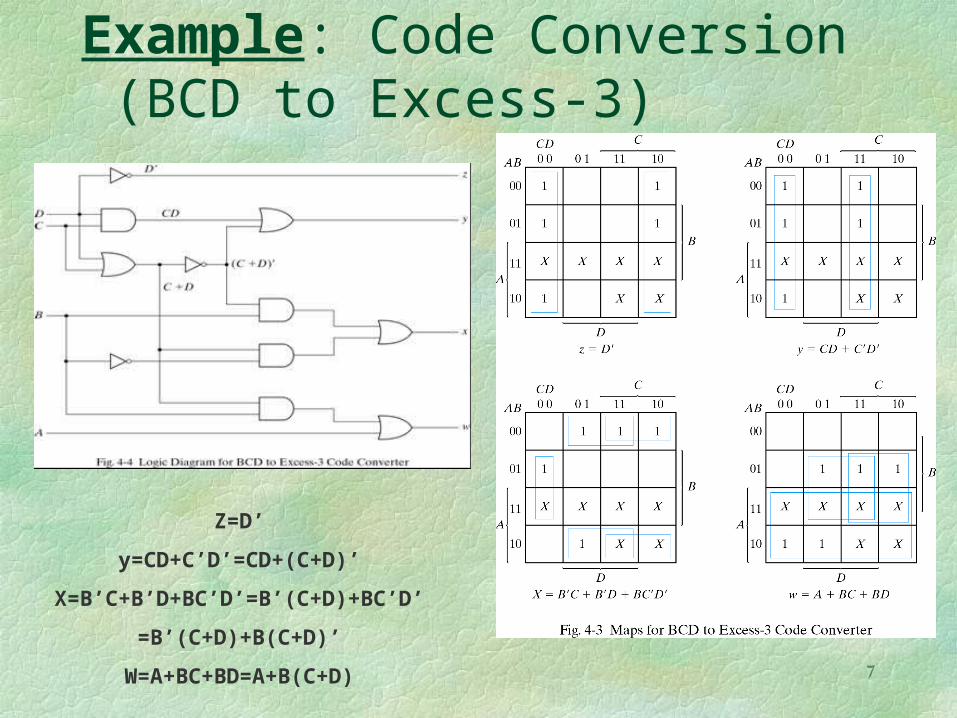
Example: Code Conversion (BCD to Excess-3)
Input BCD Output Excess-3
A B C D w x y z
0 0 0 0 0 0 1 10 0 0 1 0 1 0 0
0 0 1 0 0 1 0 1
0 0 1 1 0 1 1 00 1 0 0 0 1 1 10 1 0 1 1 0 0 00 1 1 0 1 0 0 10 1 1 1 1 0 1 01 0 0 0 1 0 1 11 0 0 1 1 1 0 0
7
Example: Code Conversion (BCD to Excess-3)
Z=D’
y=CD+C’D’=CD+(C+D)’
X=B’C+B’D+BC’D’=B’(C+D)+BC’D’
=B’(C+D)+B(C+D)’
W=A+BC+BD=A+B(C+D)
8
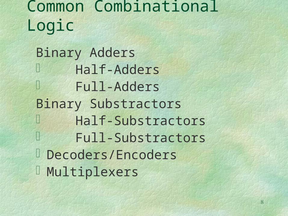
Common Combinational Logic
Binary Adders Half-Adders Full-AddersBinary Substractors Half-Substractors Full-SubstractorsDecoders/EncodersMultiplexers

9
Binary Adders
One of the basic arithmetic process in computer system
One that performs the addition of 2 bits is Half–Adder
One that performs the addition in 3 bits (2 significant bits and a previous carry) is called Full–Adder

10
Half-Adder
2 Input & 2 outputThe truth tableThus the Boolean
Function is S = x'y+xy'; C = xyThe function
cannot be further simplified
X Y C S
0 0 0 0
0 1 0 1
1 0 0 1
1 1 1 0
Truth Table

11
Half-Adder Implementations

12
Full–Adder Truth Table
3 Input (x & y as the input and z as the previous carry), & 2 output (s, c)
The truth table is :
X Y Z C S
0 0 0 0 0
0 0 1 0 1
0 1 0 0 1
0 1 1 1 0
1 0 0 0 1
1 0 1 1 0
1 1 0 1 0
1 1 1 1 1

13
Full-Adder Map

14
Full–Adder Simple Implementation
Logic Expression S = x'y'z+x'yz'+xy'z'+xyzC = xy + xz + yz
Implementation
15
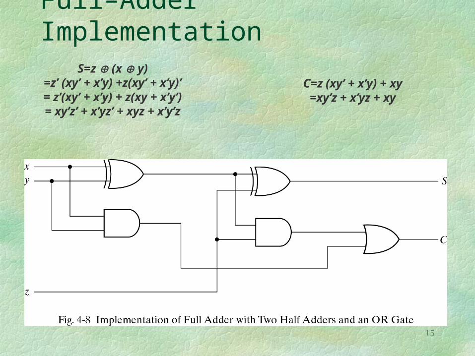
Full–Adder ImplementationS=z (x y)
=z’ (xy’ + x’y) +z(xy’ + x’y)’= z’(xy’ + x’y) + z(xy + x’y’)= xy’z’ + x’yz’ + xyz + x’y’z
C=z (xy’ + x’y) + xy=xy’z + x’yz + xy

16
Full–Adder Application

17
Example:A=1011, B=0011 then S= 1110
Subscript i 3 2 1 0
Input carry 0 1 1 0 Ci
Augend 1 0 1 1 Ai
Addend 0 0 1 1 Bi
Sum 1 1 1 0 Si
Output carry 0 0 1 1 Ci+1

18
Full–Adder Other Implementation
Pi=Ai Bi
Gi= Ai Bi
Si=Pi Ci
Ci+1= Gi + Pi Ci
Gi: Carry generate
Pi: Carry propagate

19
Carry Propagation:
The total propagation time is equal to the propagation delay of a typical gate times the number of gate levels in the circuit.
C0=input carry C1= G0+P0C0 C2=G1+P1C1=G1+P1(G0+P0C0)=G1+P1G0+P1P0C0 C3=G2+P2C2=G2+P2G1+P2P1G0+P2P1P0C0
20
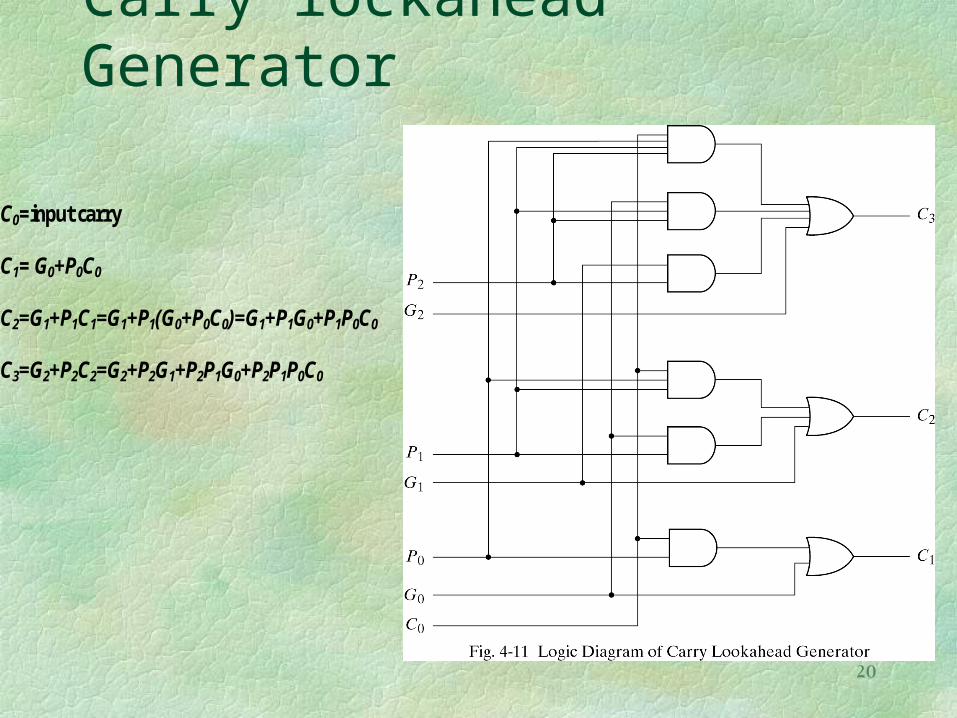
Carry lockahead Generator
C0=input carry C1= G0+P0C0 C2=G1+P1C1=G1+P1(G0+P0C0)=G1+P1G0+P1P0C0 C3=G2+P2C2=G2+P2G1+P2P1G0+P2P1P0C0

21
Adder with carry lockahead Genertaor

22
Binary SubstractorsOne of the basic arithmetic process
in computer systemOne that subtracts 2 and produce
their difference is Half-SubstractorOne that subtracts 2 and produce
their difference while taking account that 1 have been borrowed by a lower significant stage.
it is called : Full-Substractor
23
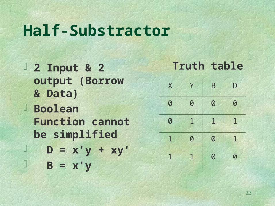
Half-Substractor
2 Input & 2 output (Borrow & Data)
Boolean Function cannot be simplified
D = x'y + xy' B = x'y
Truth table
X Y B D
0 0 0 0
0 1 1 1
1 0 0 1
1 1 0 0

24
Full-Substractor
You do it Truth table Simplify with K-Map Draw the Logic Gate

25
Adder-SubstractorThe operation A-B =A+ “1’s complement of B” +1
= A+ “2’s complement of B.For unsigned numbers, this gives A-B if A>= B
or the 2’s complement of (B-A) if A < B.For signed numbers the result is A-B provided that
there is no overflow.The addition and subtraction operations can be
combined into one circuit with one common binary adder and including an X-OR gate with each full adder.

26
Adder-Substractor
When M=0, the circuit is adder (since B 0 = B), and when M=1, the circuit
is subtractor (since B 1 = B' ).

27
Overflow
Carries: 0 1 carries:1 0
+70 0 1000110 -70 1 0111010
+80 0 1010000 -80 1 0110000
+150 1 0010110 -150 0 1101010
28
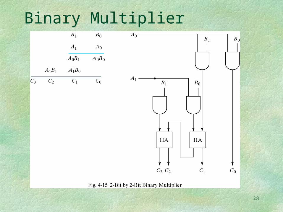
Binary Multiplier

29
4 by 3 Binary Multiplier
C1
C1
C2
C2
C2
C2
C3
C3
C3
C4
C3C4
C4
C5
C5
C0

30
Decoder
Inputs Outputs
x y z D0 D1 D2 D3 D4 D5 D6 D7
0 0 0 1 0 0 0 0 0 0 0
0 0 1 0 1 0 0 0 0 0 0
0 1 0 0 0 1 0 0 0 0 0
0 1 1 0 0 0 1 0 0 0 0
1 0 0 0 0 0 0 1 0 0 0
1 0 1 0 0 0 0 0 1 0 0
1 1 0 0 0 0 0 0 0 1 0
1 1 1 0 0 0 0 0 0 0 1

31
2-4 Line Decoder (1-4 line Demultiplexer)