1 class #25.1 civil engineering materials – cive 2110 definitions material properties concrete...
TRANSCRIPT

11
Class #25.1Class #25.1
Civil Engineering Materials – CIVE 2110Civil Engineering Materials – CIVE 2110
DefinitionsDefinitions
Material Properties Material Properties
Concrete Compressive Strength, f’Concrete Compressive Strength, f’cc
Fall 2010Fall 2010
Dr. GuptaDr. Gupta
Dr. PickettDr. Pickett

22
Advantage Disadvantage Advantage Disadvantage
Shapes Any shape Must make forms Manufactured shapes
Limited shapes
Fire resistance
1-3 Hr. resistance with NO coating
Must add
fire-proof coating
Maintenance
Less,
No need to paint
More,
Must paint for corrosion resistance
Time dependent
Creep due to long term load.
Shrinkage due to curing.
More thermal expansion and
contraction
Strength
Low tensile strength.
Low
strength/volume ratio.
High tensile strength.
High
strength/volume ratio.
Weight
Higher,
More seismic load
Lower,
Less seismic load
Stiffness
Rigid,
Less; drift, deflection, vibrations.
Flexible ,
More; drift, deflection, vibrations.
Reinforced Concrete Structural Steel

33
What is Reinforced Concrete?What is Reinforced Concrete? DefinitionDefinition: :
A construction material composed of:A construction material composed of: Course Aggregate – particles > 0.25“ diameter, retained on #4 sieve.Course Aggregate – particles > 0.25“ diameter, retained on #4 sieve. Fine Aggregate – Sand particles < 0.25” diameter, pass #4 sieve.Fine Aggregate – Sand particles < 0.25” diameter, pass #4 sieve. Water Water Cement powder Cement powder cement paste, cement paste,
Forms a gluing paste, when mixed with proper amount of waterForms a gluing paste, when mixed with proper amount of water Reinforcement bars – steel (if no reinforcement, use ACI 318, Ch.22)Reinforcement bars – steel (if no reinforcement, use ACI 318, Ch.22)
Two Methods of Reinforced Concrete Construction: Two Methods of Reinforced Concrete Construction: Cast-in-Place: : members are constructed at their final location;members are constructed at their final location;
A form (wood) or mold (steel) is built in the shape of the member,A form (wood) or mold (steel) is built in the shape of the member, Reinforcement bars are placed inside form (mold);Reinforcement bars are placed inside form (mold); Concrete is poured into form (mold).Concrete is poured into form (mold).
Pre-Cast: : members are constructed off-site;members are constructed off-site; Members are transported to their final location,Members are transported to their final location, Members are erected and joined to form a structure.Members are erected and joined to form a structure.

44
Cast-In-Place ConcreteCast-In-Place Concrete
I-75, Suder Ave. ramp
McCormac, 8th ed., p.73

55
Pre-Cast ConcretePre-Cast Concrete
Veterans Glass City Skyway bridge

66
Reinforced Concrete StructuresReinforced Concrete StructuresLoad bearing
masonry walls.
Gravity loads supported
by columns.
Fig. 4-1,MacGregor, 5th edition, 2009, Pearson/Prentice Hall
One-way slab
One-way slab
Two-way slab
One-way slab
MacGregor, 5th ed., Fig. 4-1

77
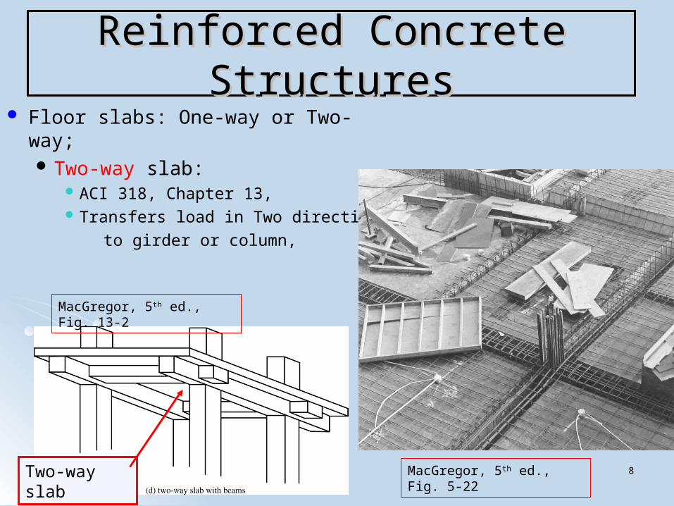
Reinforced Concrete StructuresReinforced Concrete Structures Floor slabs: One-way or Two-way;
One-way slab: Takes load in only One direction, Slab forms top flange of T-beam joist,
T-beam takes load in only One direction, Load transferred to T-beam joist, T-beam transfers load to girder, Girder transfers load to column (or wall), Column (or wall) transfers load to;
Piles, Spread footings.
- one-way slab; L- one-way slab; L2/L/L11 > 2 > 2
- two-way slab; L- two-way slab; L2/L/L1 < 2 < 2
L2
L1
One-way slab
MacGregor, 5th ed., Fig. 4-34
MacGregor, 5th ed., Fig. 4-36
88
Reinforced Concrete StructuresReinforced Concrete Structures Floor slabs: One-way or Two-way;
Two-way slab: ACI 318, Chapter 13, Transfers load in Two directions
to girder or column,
Two-way slab
MacGregor, 5th ed., Fig. 13-2
MacGregor, 5th ed., Fig. 5-22
99
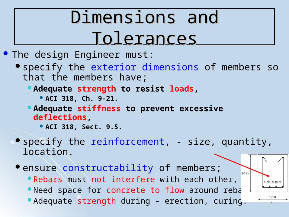
The design Engineer must:specify the exterior dimensions of members so that
the members have;Adequate strength to resist loads,
ACI 318, Ch. 9-21.Adequate stiffness to prevent excessive deflections,
ACI 318, Sect. 9.5.
specify the reinforcement, - size, quantity, location.
ensure constructability of members;Rebars must not interfere with each other,Need space for concrete to flow around rebars,Adequate strength during – erection, curing.
Dimensions and TolerancesDimensions and Tolerances

1010
Dimensions and TolerancesDimensions and Tolerances
The design Engineer should specify:Calculations;
3 significant digits,Exterior dimensions of beams, columns;
In whole inch increments, Slab thickness;
In half-inch increments, Rebar size, length;
Bar sizes are manufactured in 1/8 in. increments,Length in two-inch increments, ACI 318, Sect. 7.5.
Concrete cover;In half-inch increments,
Rebar diameter = 9/8”

1111
Dimensions and TolerancesDimensions and Tolerances
The design Engineer should ensure
construction tolerances of:Exterior dimensions of beams and columns;
0.5 inch,
Slab thickness; 0.25 inch,
Concrete cover; ACI 318, Sect. 7.5.2.1; 0.375 inch, effective depth, d 8 inch, 0.5 inch, effective depth, d > 8 inch,

1212
Material PropertiesMaterial Properties
In any beam (concrete, steel, masonry, wood): Applied loads produce
Internal resisting Couple,Tension and Compression
forces form couple.
Positive bending moment, Axial Compression forces
in the top regions,Axial Tension forces
in the bottom regions,
MacGregor, 5th ed., Fig. 1-4
1313
Material PropertiesMaterial Properties
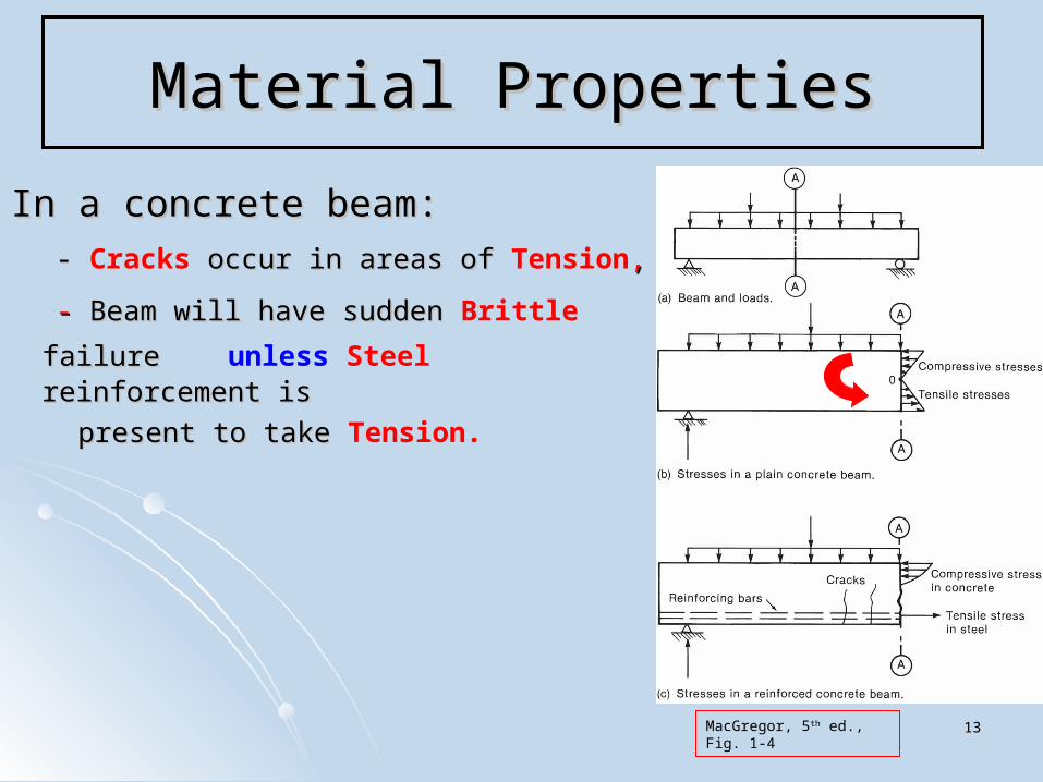
In a concrete beam:In a concrete beam:
- - Cracks occur in areas of occur in areas of Tension,,
- - Beam will have sudden Beam will have sudden Brittle failure failure unless Steel reinforcement is reinforcement is
present to take present to take Tension.
MacGregor, 5th ed., Fig. 1-4

1414
Material PropertiesMaterial Properties
Concrete is: Strong in Compression, Weak in Tension,
Cracks occur in Concrete when:Cracks occur in Concrete when:
Tensile Stress can be due to:Tensile Stress can be due to:LoadsLoadsRestrained shrinkage during curing Restrained shrinkage during curing Temperature changes Temperature changes
ConcreteofStrengthTensileConcreteinStressTensile
'10.005.0 ct ff

1515
Material PropertiesMaterial Properties
= Specified Compressive Strength of Concrete Nominal strength ( n ) is based upon
Design Strength ≥ Required StrengthReduced Nominal Strength ≥ Factored Up Load
n ≥ U
ACI 318, Sect. 5.3;ACI 318, Sect. 5.3; In order to validate a specifiedIn order to validate a specified , concrete plant must have;, concrete plant must have;
Strength test records Strength test records 12 months old, 12 months old, A sample standard deviation, A sample standard deviation,
established from 30 consecutive compressive strength testsestablished from 30 consecutive compressive strength tests 2 cylinders tested per test 2 cylinders tested per test
'cf
'cf
'cf
ss

1616
Material PropertiesMaterial Properties
ACI 318, Sect. 5.3;ACI 318, Sect. 5.3; In order to validate a specifiedIn order to validate a specified ;;
A Required Average Compressive Strength, , must be obtained;A Required Average Compressive Strength, , must be obtained;
ForFor
Use the Use the larger value computed from Eq. (5-1) and Eq. (5-2); computed from Eq. (5-1) and Eq. (5-2); Eq. (5-1)Eq. (5-1)
Eq. (5-2)Eq. (5-2)
Eq. (5-1) is based on a probability of 1-in-100 that the average of Eq. (5-1) is based on a probability of 1-in-100 that the average of 3 consecutive tests may < specified.3 consecutive tests may < specified.
Eq. (5.2) is based on a probability of 1-in-100 that an individual test Eq. (5.2) is based on a probability of 1-in-100 that an individual test may be more than 500 psi below specified.may be more than 500 psi below specified.
sccr sff 34.1''
'cf '
crfpsifc 5000'
50033.2'' sccr sff
'cf
'cf

1717
Material PropertiesMaterial Properties
ACI 318, Sect. 5.3;ACI 318, Sect. 5.3; In order to validate a specifiedIn order to validate a specified ;;
A Required Average Compressive Strength, , must be obtained;A Required Average Compressive Strength, , must be obtained;
ForFor
Use the Use the larger value computed from Eq. (5-1) and Eq. (5-3); computed from Eq. (5-1) and Eq. (5-3); Eq. (5-1)Eq. (5-1)
Eq. (5-3)Eq. (5-3)
Eq. (5-1) is based on a probability of 1-in-100 that the average of Eq. (5-1) is based on a probability of 1-in-100 that the average of 3 consecutive tests may < specified.3 consecutive tests may < specified.
Eq. (5.3) is based on a probability of 1-in-100 that an individual test Eq. (5.3) is based on a probability of 1-in-100 that an individual test may be < specified.may be < specified.
sccr sff 34.1''
'cf
'crf
psifc 5000'
sccr sff 33.290.0 ''
'cf
'90.0 cf

1818
Material PropertiesMaterial Properties
ACI 318, Compressive Strength Test;ACI 318, Compressive Strength Test; Standard Cylinders;Standard Cylinders; Concrete samples taken per ASTM C172, Concrete samples taken per ASTM C172, Concrete samples molded, cured per ASTM C31,Concrete samples molded, cured per ASTM C31, Concrete strength tested per ASTM C39;Concrete strength tested per ASTM C39;
6”x12” cylinders, 6”x12” cylinders, Fill cylinder with concrete,Fill cylinder with concrete, Allow concrete to harden in cylinder,Allow concrete to harden in cylinder,
24 hours, 6024 hours, 60˚̊ 80˚F, no moisture loss, 80˚F, no moisture loss, Strip the cylinder mold,Strip the cylinder mold,
Place cylinder in a curing room (100% humidity) Place cylinder in a curing room (100% humidity) or water tank at or water tank at 72˚F,72˚F,
After 28 days, After 28 days, Load 2 cylinders in compression at rate of 35 psi/sec.Load 2 cylinders in compression at rate of 35 psi/sec. Record failure load, calculate failure stress.Record failure load, calculate failure stress.
ComprApC max
ComprApC max
6”
12”
1919
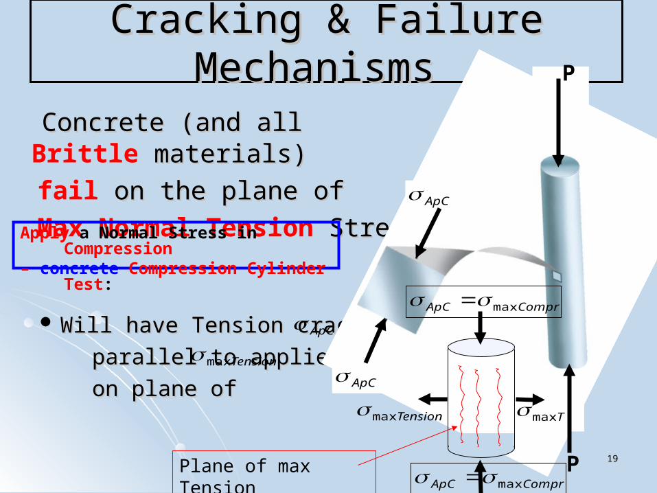
Cracking & Failure Mechanisms Cracking & Failure Mechanisms
Concrete (and all Concrete (and all Brittle materials) materials)
fail on the plane of on the plane of
Max Normal Tension Stress Stress
Will have Tension cracksWill have Tension cracks
parallel to applied load, parallel to applied load,
on plane of on plane of ApC
ApC
P
P
Apply a Normal Stress in Compression – concrete Compression Cylinder Test:
ApC
Tensionmax
ComprApC max
ComprApC max
Tensionmax Tmax
Plane of max Tension

2020
Mohr’s Circle Method – Failure ModesMohr’s Circle Method – Failure ModesApply a Normal Stress in Compression – Split Cylinder Test:
max
ApC
Ductile Material fails by Buckling.
Brittle Material fails on plane of max
NORMAL (Tension) Stress,
Failure stress is 2x90˚=180˚
on Mohr Circle from applied stress
90˚ApC min
2maxApC
2x90˚
Steel Ductile
Concrete
Brittle
tension
90˚Plane of max Tension
Tensionmax
ApCTensionmax
CompressionTension
ApC

2121
Mohr’s Circle Method – Failure ModesMohr’s Circle Method – Failure ModesApply a Normal Stress in Tension:
ApT max
ApT
Ductile Material fails on plane of
From to failure stress = 2x45˚=90˚
on Mohr Circle
Brittle Material fails on plane of
acts on plane perpendicular
to applied Tension load.
45˚
45˚
45˚
45˚
90˚0min
2maxApT
2x45˚
Steel Ductile
Cast Iron Plexiglass
Brittle
Plane of max Tension
maxTensionmax
TensionmaxTensionmax
max
max
TensionCompression

2222
Mohr’s Circle Method – Failure ModesMohr’s Circle Method – Failure Modes
ionslightTensmax
Brittle concrete fails on plane of max normal (tension) Stress.
Failure stress located at: 2x90˚=180˚on Mohr Circle
ApC min
2maxApC
2x45˚
2x90˚
tension
Shear Stress Normal Stress Principal Stress
Neutral Axis
90˚
tension
Plane of max Tension
Concrete Brittle

2323
Cracking & Failure Mechanisms Cracking & Failure Mechanisms
Concrete cracking process;Concrete cracking process; - - 4 stages: : (MacGregor, 5(MacGregor, 5thth ed., pp. 41-43) ed., pp. 41-43)
(0) Overall Cracking Process ; ;- individually, cement paste & aggregateindividually, cement paste & aggregate
each have brittle, linear stress-strain curves,each have brittle, linear stress-strain curves,- during a cylinder compression test,during a cylinder compression test,
- friction between test machine head-plates and cylinder ends,friction between test machine head-plates and cylinder ends,- prevents lateral expansion at cylinder ends,prevents lateral expansion at cylinder ends,- this restrains vertical cracking near cylinder endsthis restrains vertical cracking near cylinder ends,,
- this strengthens conical regions near cylinder ends,this strengthens conical regions near cylinder ends,- vertical cracks at mid-height of cylinder do not enter conical regions.vertical cracks at mid-height of cylinder do not enter conical regions.
ApC
ApC
But, in the concrete mixture, But, in the concrete mixture, the cement paste & aggregate together the cement paste & aggregate together produce a non-linear stress-strain curve, produce a non-linear stress-strain curve, that appears slightlythat appears slightly ductile,ductile,
due to the gradual micro-cracking due to the gradual micro-cracking within the mixture and within the mixture and redistribution of stress throughoutredistribution of stress throughout the concrete mixture.the concrete mixture.
(MacGregor, 5th ed., Fig. 3.13)

2424
Cracking & Failure Mechanisms Cracking & Failure Mechanisms
Concrete cracking process;Concrete cracking process; - - 4 stages: : (MacGregor, 5(MacGregor, 5thth ed., pp. 41-43) ed., pp. 41-43)
(1) No-Load Bond Cracking during curing; during curing;
- cement paste shrinks,- cement paste shrinks,
- shrinkage restrained by non-shrinking - shrinkage restrained by non-shrinking aggregate,aggregate,
- shrinkage causes tension in the concrete,- shrinkage causes tension in the concrete,
- - No-Load Bond Cracks occur along interface occur along interface
between cement paste and aggregate,between cement paste and aggregate,
- cracks have little effect on concrete at low loads,- cracks have little effect on concrete at low loads,
- stress-strain curve remains nearly linear up to - stress-strain curve remains nearly linear up to
'3.00 cApC f
'3.0 cApC f
ApC

2525
Cracking & Failure Mechanisms Cracking & Failure Mechanisms
(MacGregor, 5(MacGregor, 5thth ed., Fig. 3.1) ed., Fig. 3.1)
'3.0 cf
'5.0 cf
'75.0 cf
'cf

2626
Cracking & Failure Mechanisms Cracking & Failure Mechanisms
Concrete cracking process;Concrete cracking process; - - 4 stages: : (MacGregor, 5(MacGregor, 5thth ed., pp. 41-43) ed., pp. 41-43)
(2) Stable Crack Initiation ; ;
- - Bond Cracks occur from one aggregate to occur from one aggregate to
another piece of aggregate,another piece of aggregate,
- cracks are stable, - cracks are stable,
- cracks will propagate only if load is increased,- cracks will propagate only if load is increased,
- additional load is redistributed to un-cracked - additional load is redistributed to un-cracked portions,portions,
- causes gradual curving of stress-strain curve. - causes gradual curving of stress-strain curve.
ApC
'5.03.0 cApC f
2727
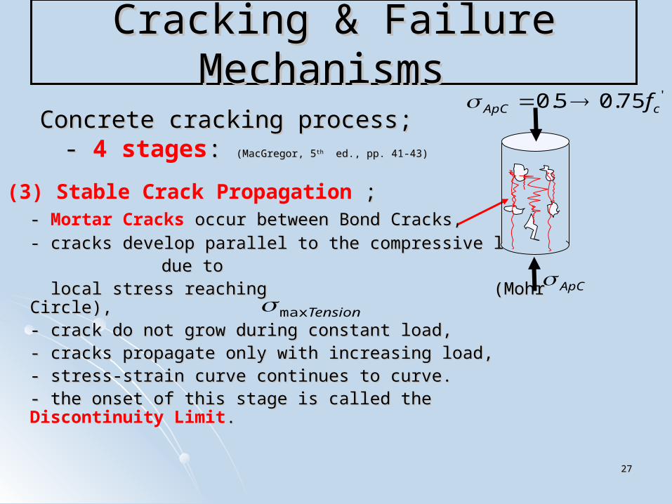
Cracking & Failure Mechanisms Cracking & Failure Mechanisms
Concrete cracking process;Concrete cracking process; - - 4 stages: : (MacGregor, 5(MacGregor, 5thth ed., pp. 41-43) ed., pp. 41-43)
(3) Stable Crack Propagation ; ;- - Mortar Cracks occur between Bond Cracks, occur between Bond Cracks,
- cracks develop parallel to the compressive load, - cracks develop parallel to the compressive load, due todue to
local stress reaching (Mohr Circle),local stress reaching (Mohr Circle),- crack do not grow during constant load,- crack do not grow during constant load,- cracks propagate only with increasing load,- cracks propagate only with increasing load,
- stress-strain curve continues to curve. - stress-strain curve continues to curve. - the onset of this stage is called the - the onset of this stage is called the Discontinuity
Limit..
ApC
'75.05.0 cApC f
Tensionmax
2828
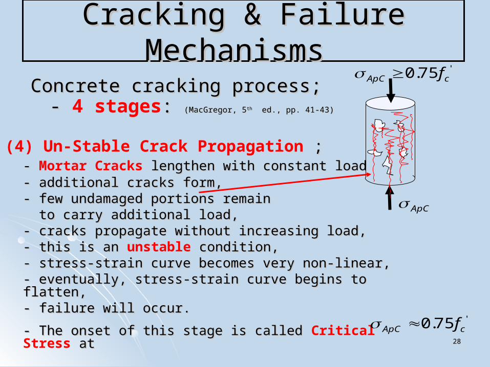
Cracking & Failure Mechanisms Cracking & Failure Mechanisms
Concrete cracking process;Concrete cracking process; - - 4 stages: : (MacGregor, 5(MacGregor, 5thth ed., pp. 41-43) ed., pp. 41-43)
(4) Un-Stable Crack Propagation ; ;- - Mortar Cracks lengthen with constant load, lengthen with constant load,- additional cracks form,- additional cracks form,- few undamaged portions remain- few undamaged portions remain to carry additional load,to carry additional load,- cracks propagate without increasing load,- cracks propagate without increasing load,- this is an - this is an unstable condition, condition,
- stress-strain curve becomes very non-linear,- stress-strain curve becomes very non-linear,- eventually, stress-strain curve begins to flatten,- eventually, stress-strain curve begins to flatten,- failure will occur.- failure will occur.
- The onset of this stage is called - The onset of this stage is called Critical Stress at at
ApC
'75.0 cApC f
'75.0 cApC f

2929
Cracking & Failure Mechanisms Cracking & Failure Mechanisms
Concrete cracking process;Concrete cracking process; - - 4 stages: : (MacGregor, 5(MacGregor, 5thth ed., pp. 41-43)) ed., pp. 41-43))
(4) Un-Stable Crack Propagation ; ;- - Critical Stress; - significant lateral strains caused by lateral strains caused by
large amount of micro cracks,large amount of micro cracks, - volumetric strain increases, significantly,- volumetric strain increases, significantly, - causes outward force on lateral confining reinforcement,- causes outward force on lateral confining reinforcement,
- spirals, - spirals, - lateral ties,- lateral ties,
- confining reinforcement becomes in Tension, - confining reinforcement becomes in Tension, - confining Steel restrains concrete expansion and disintegration,- confining Steel restrains concrete expansion and disintegration, - puts column in a state of Triaxial Compressive Stress. - puts column in a state of Triaxial Compressive Stress.
ApC
'75.0 cApC f
'75.0 cApC f
3030
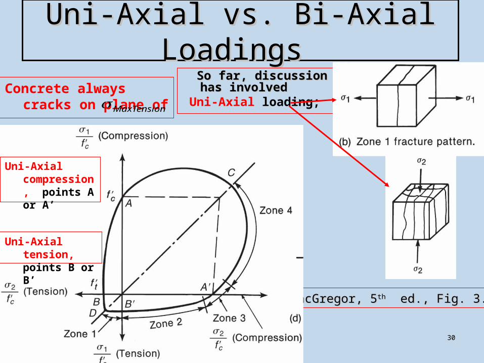
Uni-Axial vs. Bi-Axial Loadings Uni-Axial vs. Bi-Axial Loadings So far, discussion has So far, discussion has
involvedinvolved Uni-Axial loading;
(MacGregor, 5(MacGregor, 5thth ed., Fig. 3.12) ed., Fig. 3.12)
Uni-Axial tension, points B or B’
Uni-Axial compression, points A or A’
Concrete always cracks on plane of MaxTension

3131
Uni-Axial vs. Bi-Axial Loadings Uni-Axial vs. Bi-Axial Loadings
(MacGregor, 5(MacGregor, 5thth ed., Fig. 3.12) ed., Fig. 3.12)
Bi-Axial Compression; from points A-C-A’
- Delays the formation of - Bond Cracks- Bond Cracks
- Mortar Cracks- Mortar Cracks
- Stable crack propagation - longer time - Stable crack propagation - longer time
- higher load- higher load
Due to Bi-Axial Compression; failure at point C ≈ '07.1 cf

3232
Tri-Axial Loadings Tri-Axial Loadings
(MacGregor, 5(MacGregor, 5thth ed., Fig. 3.15) ed., Fig. 3.15)
(MacGregor, 5(MacGregor, 5thth ed., Fig. 3.16) ed., Fig. 3.16)33.4 Failure
Tri-axial Compression ;
- Compared to uni-axial compression;
- higher compressive
strength,
- more ductile,
In columns: In columns: - Uni-axial compression causes Uni-axial compression causes
outward force on outward force on lateral confining reinforcement, lateral confining reinforcement, - spirals - spirals - ties- ties- confining Steel restrains concrete - confining Steel restrains concrete
expansion and disintegration,expansion and disintegration,- reinforcement becomes in Tension, - reinforcement becomes in Tension,
as it restrains concrete expansion as it restrains concrete expansion - puts column into - puts column into Triaxial Compression
3333
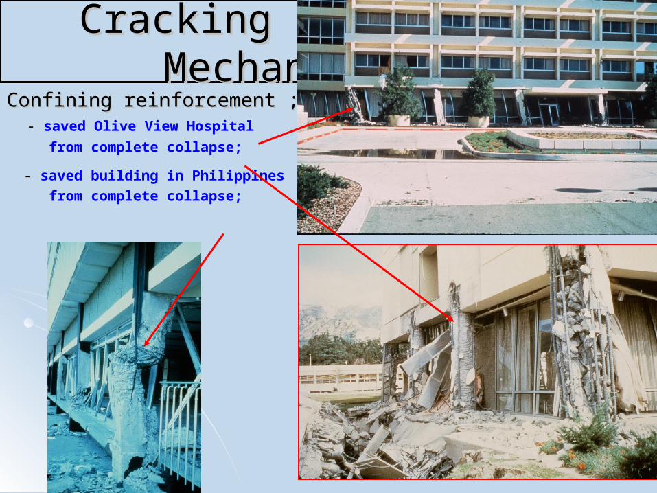
Cracking & Failure Mechanisms Cracking & Failure Mechanisms Confining reinforcement ;Confining reinforcement ; - - saved Olive View Hospital
from complete collapse;
- - saved building in Philippines
from complete collapse;
3434
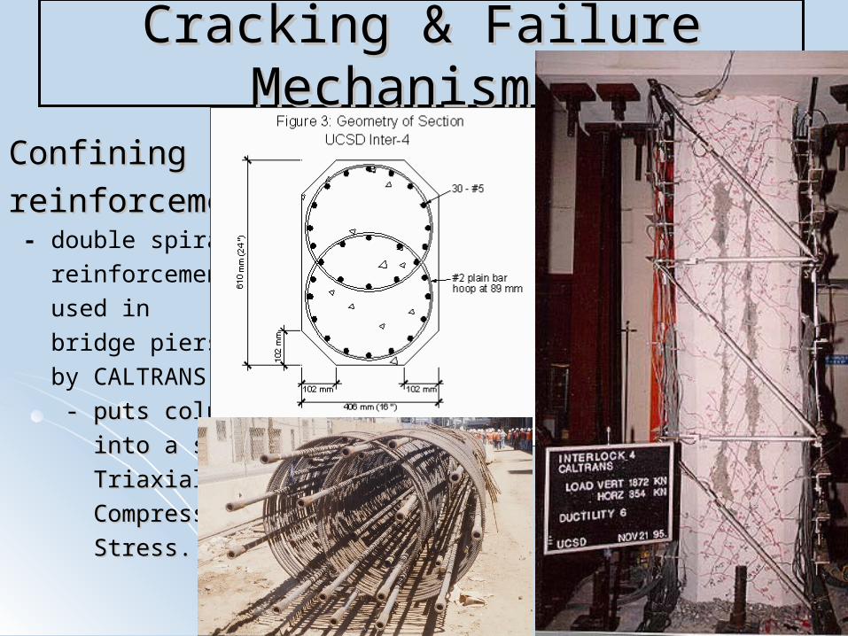
Cracking & Failure Mechanisms Cracking & Failure Mechanisms
ConfiningConfining
reinforcement ;reinforcement ; - double spiral
reinforcement
used in
bridge piers
by CALTRANS,
- puts column - puts column
into a state of into a state of
Triaxial Triaxial
CompressiveCompressive
Stress. Stress.