1 chain bracket 2 strain relief - murri oy · mp classic mp 41 system overview 1 2 3 1 chain...
TRANSCRIPT
MP ClassicMP 41
System overview
1
2
3
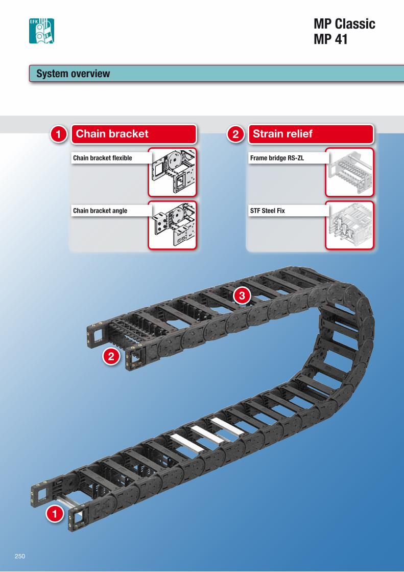
1 Chain bracket
Chain bracket flexible
Chain bracket angle
2 Strain relief
Frame bridge RS-ZL
STF Steel Fix
250
251
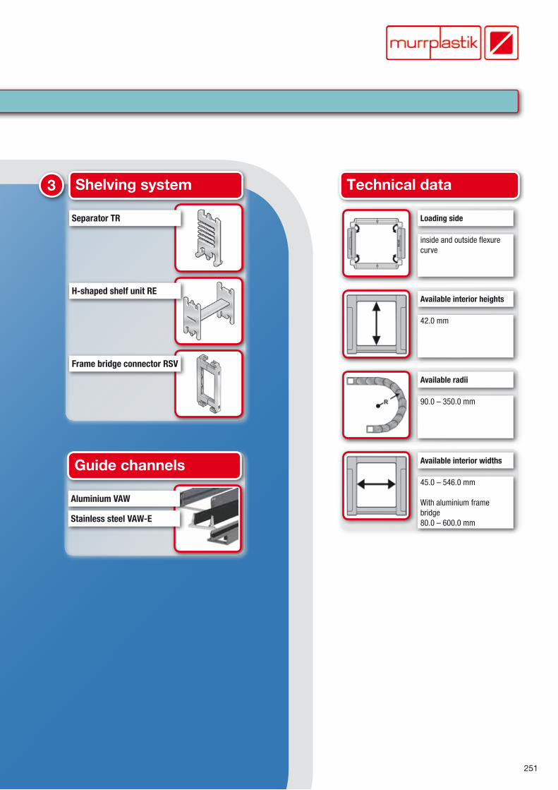
3 Shelving system
Separator TR
H-shaped shelf unit RE
Frame bridge connector RSV
Guide channels
Aluminium VAW
Stainless steel VAW-E
Technical data
Loading side
inside and outside flexure curve
Available interior heights
42.0 mm
Available radii
90.0 – 350.0 mm
Available interior widths
45.0 – 546.0 mm
With aluminium frame bridge80.0 – 600.0 mm
252
MP ClassicMP 41
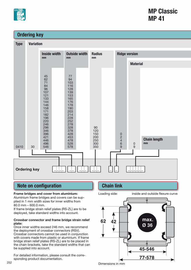
Ordering key
0410
Type
30
Variation
4562718496
107121133144146158171182196220246296346396421446496546
Inside widthmm
7794103116128139153165176178190203214228252278328378428453478528578
Outside widthmm
90120150200250300350
Radiusmm
02469
Ridge version
09
Material
Chain lengthmm
Ordering key _ _ _ _ _ _ _ _ _ _ _ _ _ _ _ _ _ _ _ _
Note on configurationFrame bridges and cover from aluminium:Aluminium frame bridges and covers can be sup-plied in 1 mm width sizes for inner widths from 80.0 mm – 600.0 mm.If frame bridge strain relief plates (RS-ZL) are to be deployed, take standard widths into account.
Crossbar connector and frame bridge strain relief plate:Once inner widths exceed 246 mm, we recommend the deployment of crossbar connectors (RSV).Crossbar connectors cannot be used in conjunction with covers made from plastic or aluminium. If frame bridge strain relief plates (RS-ZL) are to be placed in the chain brackets, take the standard widths that can be supplied into account.
For detailed information, please consult the corre-sponding product documentation.
Chain linkLoading side: inside and outside flexure curve
Dimensions in mm
253
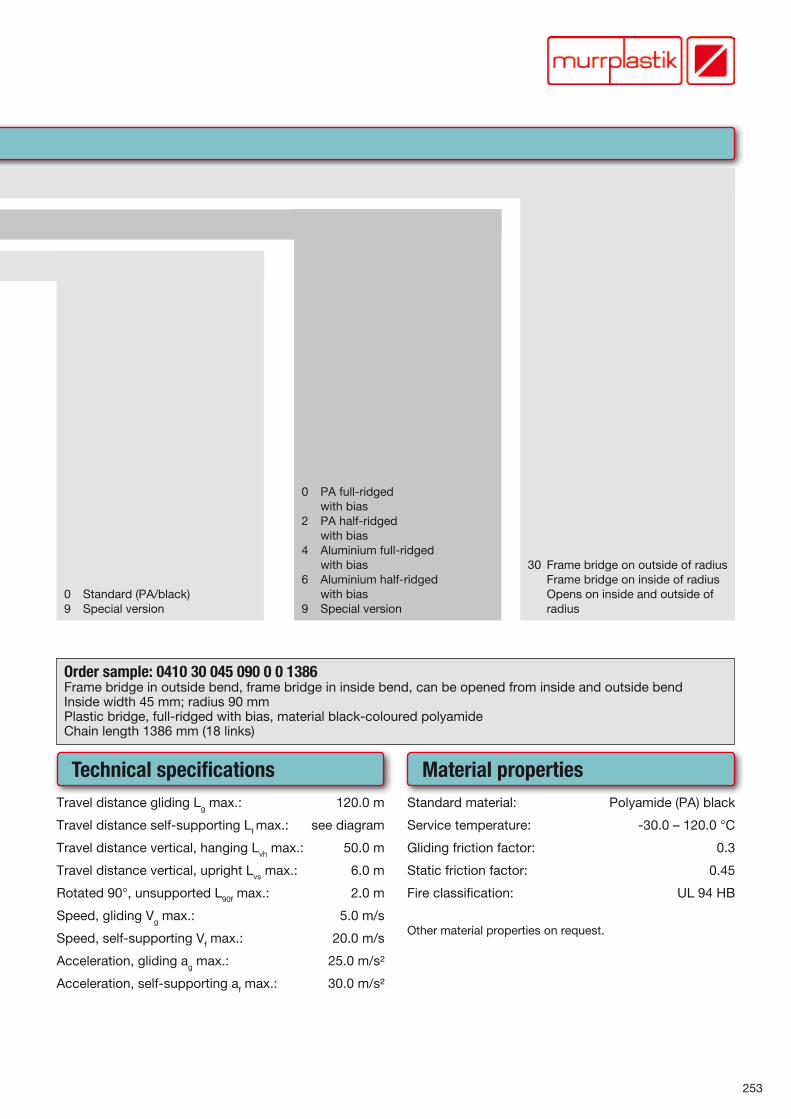
30 Frame bridge on outside of radius Frame bridge on inside of radius Opens on inside and outside of
radius
0 PA full-ridged with bias2 PA half-ridged with bias4 Aluminium full-ridged with bias6 Aluminium half-ridged with bias9 Special version
0 Standard (PA/black)9 Special version
Order sample: 0410 30 045 090 0 0 1386Frame bridge in outside bend, frame bridge in inside bend, can be opened from inside and outside bendInside width 45 mm; radius 90 mmPlastic bridge, full-ridged with bias, material black-coloured polyamideChain length 1386 mm (18 links)
Technical specificationsTravel distance gliding Lg max.: 120.0 m
Travel distance self-supporting Lf max.: see diagram
Travel distance vertical, hanging Lvh max.: 50.0 m
Travel distance vertical, upright Lvs max.: 6.0 m
Rotated 90°, unsupported L90f max.: 2.0 m
Speed, gliding Vg max.: 5.0 m/s
Speed, self-supporting Vf max.: 20.0 m/s
Acceleration, gliding ag max.: 25.0 m/s²
Acceleration, self-supporting af max.: 30.0 m/s²
Material propertiesStandard material: Polyamide (PA) black
Service temperature: -30.0 – 120.0 °C
Gliding friction factor: 0.3
Static friction factor: 0.45
Fire classification: UL 94 HB
Other material properties on request.
254
MP ClassicMP 41
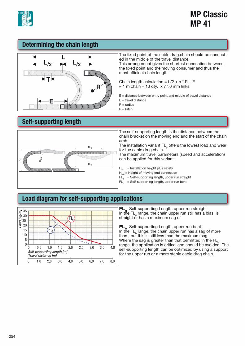
Determining the chain lengthThe fixed point of the cable drag chain should be connect-ed in the middle of the travel distance.This arrangement gives the shortest connection between the fixed point and the moving consumer and thus the most efficient chain length. Chain length calculation = L/2 + π * R + E≈ 1 m chain = 13 qty. x 77.0 mm links. E = distance between entry point and middle of travel distanceL = travel distanceR = radiusP = Pitch
Self-supporting length
FL
FL b
g
H HM
A
S
The self-supporting length is the distance between the chain bracket on the moving end and the start of the chain arch.The installation variant FLg offers the lowest load and wear for the cable drag chain.The maximum travel parameters (speed and acceleration) can be applied for this variant. HS = Installation height plus safetyHMA = Height of moving end connectionFLg = Self-supporting length, upper run straightFLb = Self-supporting length, upper run bent
Load diagram for self-supporting applicationsFLg Self-supporting Length, upper run straightIn the FLg range, the chain upper run still has a bias, is straight or has a maximum sag of
FLb Self-supporting Length, upper run bentIn the FLb range, the chain upper run has a sag of more than , but this is still less than the maximum sag.Where the sag is greater than that permitted in the FLb range, the application is critical and should be avoided. The self-supporting length can be optimized by using a support for the upper run or a more stable cable drag chain.
255
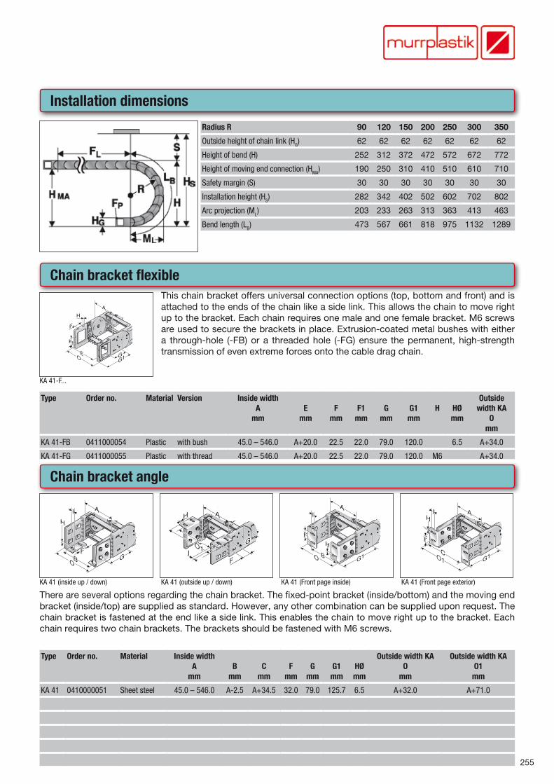
Installation dimensions
Radius R 90 120 150 200 250 300 350
Outside height of chain link (HG) 62 62 62 62 62 62 62
Height of bend (H) 252 312 372 472 572 672 772
Height of moving end connection (HMA) 190 250 310 410 510 610 710
Safety margin (S) 30 30 30 30 30 30 30
Installation height (HS) 282 342 402 502 602 702 802
Arc projection (ML) 203 233 263 313 363 413 463
Bend length (LB) 473 567 661 818 975 1132 1289
Chain bracket flexible
KA 41-F...
This chain bracket offers universal connection options (top, bottom and front) and is attached to the ends of the chain like a side link. This allows the chain to move right up to the bracket. Each chain requires one male and one female bracket. M6 screws are used to secure the brackets in place. Extrusion-coated metal bushes with either a through-hole (-FB) or a threaded hole (-FG) ensure the permanent, high-strength transmission of even extreme forces onto the cable drag chain.
Type Order no. Material Version Inside widthA
mmE
mmF
mmF1
mmG
mmG1
mmH HØ
mm
Outside width KA
Omm
KA 41-FB 0411000054 Plastic with bush 45.0 – 546.0 A+20.0 22.5 22.0 79.0 120.0 6.5 A+34.0
KA 41-FG 0411000055 Plastic with thread 45.0 – 546.0 A+20.0 22.5 22.0 79.0 120.0 M6 A+34.0
Chain bracket angle
KA 41 (inside up / down) KA 41 (outside up / down) KA 41 (Front page inside) KA 41 (Front page exterior)
There are several options regarding the chain bracket. The fixed-point bracket (inside/bottom) and the moving end bracket (inside/top) are supplied as standard. However, any other combination can be supplied upon request. The chain bracket is fastened at the end like a side link. This enables the chain to move right up to the bracket. Each chain requires two chain brackets. The brackets should be fastened with M6 screws.
Type Order no. Material Inside widthA
mmB
mmC
mmF
mmG
mmG1
mmHØmm
Outside width KAO
mm
Outside width KAO1
mm
KA 41 0410000051 Sheet steel 45.0 – 546.0 A-2.5 A+34.5 32.0 79.0 125.7 6.5 A+32.0 A+71.0
256
MP ClassicMP 41
Shelving system (Continued...)Shelving system
Shelving system
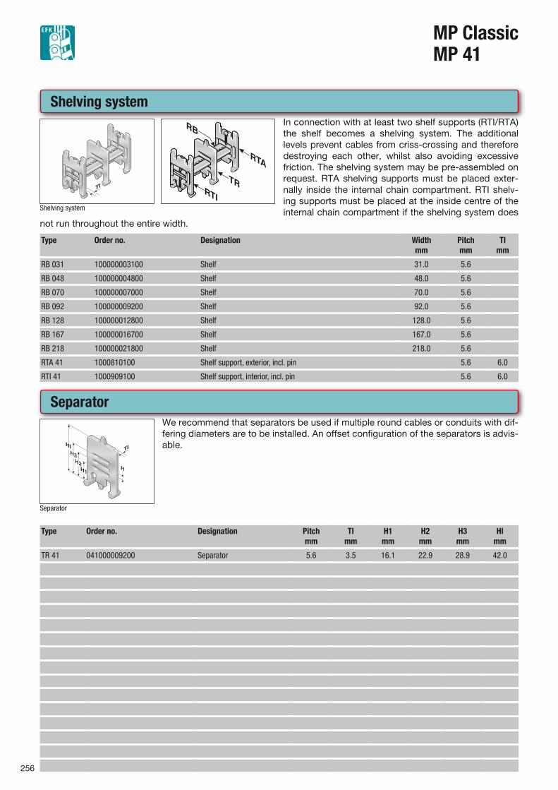
In connection with at least two shelf supports (RTI/RTA) the shelf becomes a shelving system. The additional levels prevent cables from criss-crossing and therefore destroying each other, whilst also avoiding excessive friction. The shelving system may be pre-assembled on request. RTA shelving supports must be placed exter-nally inside the internal chain compartment. RTI shelv-ing supports must be placed at the inside centre of the internal chain compartment if the shelving system does
not run throughout the entire width.
Type Order no. Designation Widthmm
Pitchmm
TImm
RB 031 100000003100 Shelf 31.0 5.6
RB 048 100000004800 Shelf 48.0 5.6
RB 070 100000007000 Shelf 70.0 5.6
RB 092 100000009200 Shelf 92.0 5.6
RB 128 100000012800 Shelf 128.0 5.6
RB 167 100000016700 Shelf 167.0 5.6
RB 218 100000021800 Shelf 218.0 5.6
RTA 41 1000810100 Shelf support, exterior, incl. pin 5.6 6.0
RTI 41 1000909100 Shelf support, interior, incl. pin 5.6 6.0
Separator
Separator
We recommend that separators be used if multiple round cables or conduits with dif-fering diameters are to be installed. An offset configuration of the separators is advis-able.
Type Order no. Designation Pitchmm
TImm
H1mm
H2mm
H3mm
HImm
TR 41 041000009200 Separator 5.6 3.5 16.1 22.9 28.9 42.0
257
Shelf unit
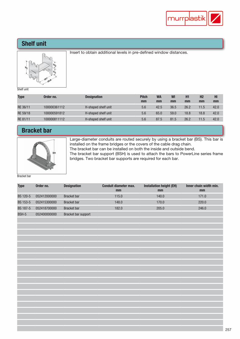
Shelf unit
Insert to obtain additional levels in pre-defined window distances.
Type Order no. Designation Pitchmm
WAmm
WImm
H1mm
H2mm
HImm
RE 36/11 100000361112 H-shaped shelf unit 5.6 42.5 36.5 26.2 11.5 42.0
RE 59/18 100000591812 H-shaped shelf unit 5.6 65.0 59.0 18.8 18.8 42.0
RE 81/11 100000811112 H-shaped shelf unit 5.6 87.5 81.5 26.2 11.5 42.0
Bracket bar
Bracket bar
Large-diameter conduits are routed securely by using a bracket bar (BS). This bar is installed on the frame bridges or the covers of the cable drag chain.The bracket bar can be installed on both the inside and outside bend.The bracket bar support (BSH) is used to attach the bars to PowerLine series frame bridges. Two bracket bar supports are required for each bar.
Type Order no. Designation Conduit diameter max.mm
Installation height (EH)mm
Inner chain width min.mm
BS 120-5 052412000000 Bracket bar 115.0 140.0 171.0
BS 153-5 052415300000 Bracket bar 148.0 170.0 220.0
BS 187-5 052418700000 Bracket bar 182.0 205.0 246.0
BSH-5 052400000000 Bracket bar support
258
MP ClassicMP 41
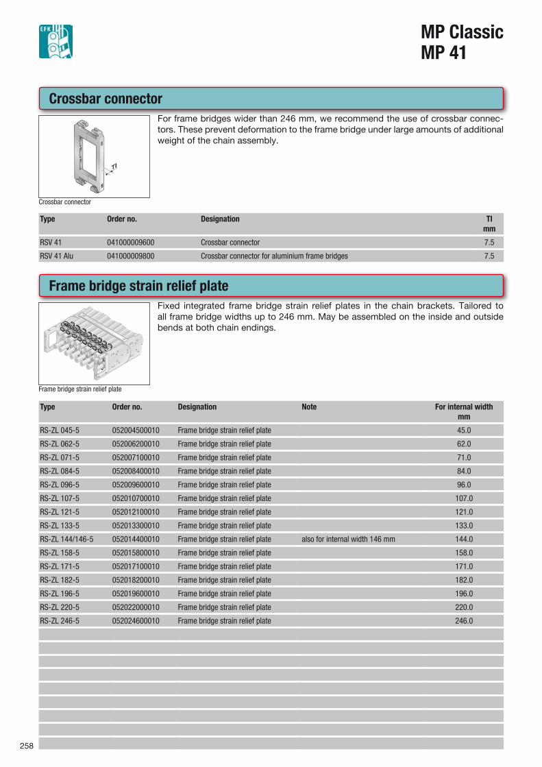
Crossbar connector
Crossbar connector
For frame bridges wider than 246 mm, we recommend the use of crossbar connec-tors. These prevent deformation to the frame bridge under large amounts of additional weight of the chain assembly.
Type Order no. Designation TImm
RSV 41 041000009600 Crossbar connector 7.5
RSV 41 Alu 041000009800 Crossbar connector for aluminium frame bridges 7.5
Frame bridge strain relief plate
Frame bridge strain relief plate
Fixed integrated frame bridge strain relief plates in the chain brackets. Tailored to all frame bridge widths up to 246 mm. May be assembled on the inside and outside bends at both chain endings.
Type Order no. Designation Note For internal widthmm
RS-ZL 045-5 052004500010 Frame bridge strain relief plate 45.0
RS-ZL 062-5 052006200010 Frame bridge strain relief plate 62.0
RS-ZL 071-5 052007100010 Frame bridge strain relief plate 71.0
RS-ZL 084-5 052008400010 Frame bridge strain relief plate 84.0
RS-ZL 096-5 052009600010 Frame bridge strain relief plate 96.0
RS-ZL 107-5 052010700010 Frame bridge strain relief plate 107.0
RS-ZL 121-5 052012100010 Frame bridge strain relief plate 121.0
RS-ZL 133-5 052013300010 Frame bridge strain relief plate 133.0
RS-ZL 144/146-5 052014400010 Frame bridge strain relief plate also for internal width 146 mm 144.0
RS-ZL 158-5 052015800010 Frame bridge strain relief plate 158.0
RS-ZL 171-5 052017100010 Frame bridge strain relief plate 171.0
RS-ZL 182-5 052018200010 Frame bridge strain relief plate 182.0
RS-ZL 196-5 052019600010 Frame bridge strain relief plate 196.0
RS-ZL 220-5 052022000010 Frame bridge strain relief plate 220.0
RS-ZL 246-5 052024600010 Frame bridge strain relief plate 246.0
259
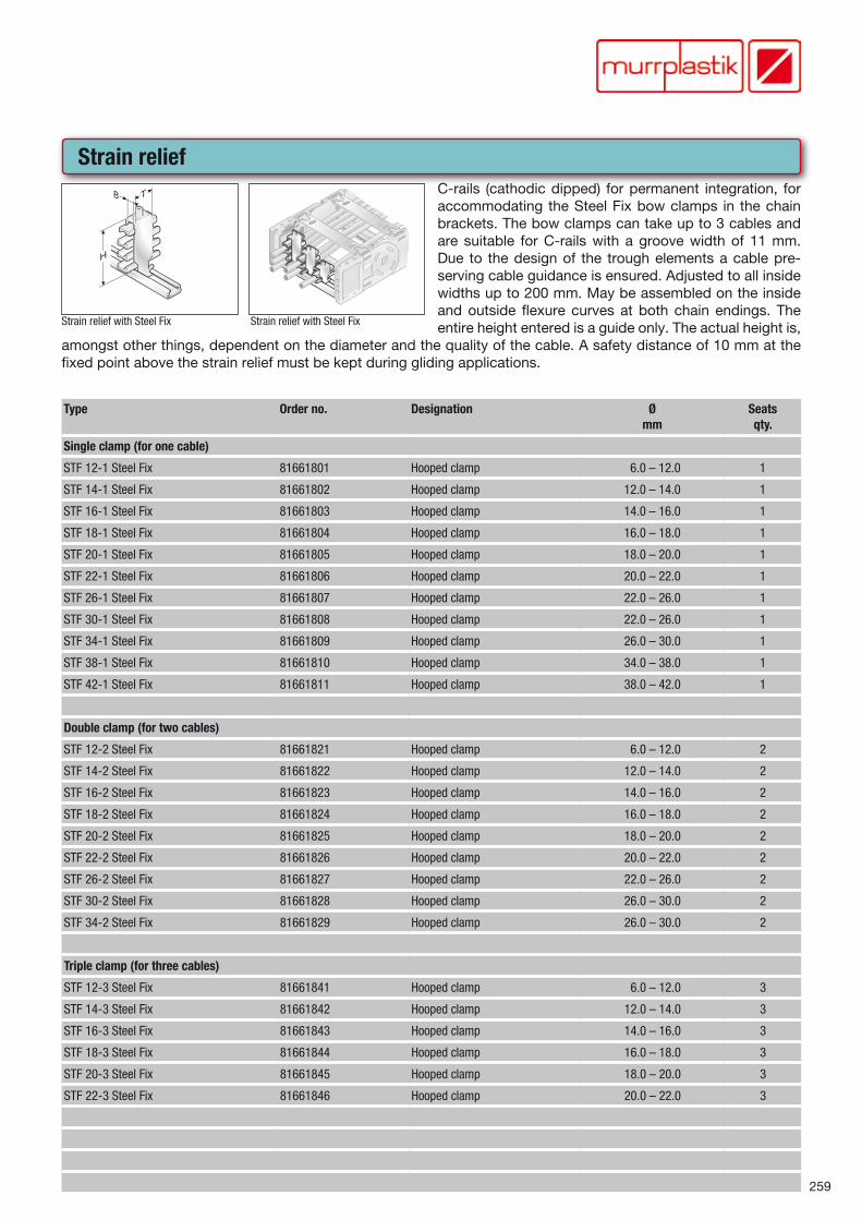
Strain relief
Strain relief with Steel Fix
TB
H
Strain relief with Steel Fix
AB C D E F G H
I
I H G F E D C
BA
B C D E F G H I
C-rails (cathodic dipped) for permanent integration, for accommodating the Steel Fix bow clamps in the chain brackets. The bow clamps can take up to 3 cables and are suitable for C-rails with a groove width of 11 mm. Due to the design of the trough elements a cable pre-serving cable guidance is ensured. Adjusted to all inside widths up to 200 mm. May be assembled on the inside and outside flexure curves at both chain endings. The entire height entered is a guide only. The actual height is,
amongst other things, dependent on the diameter and the quality of the cable. A safety distance of 10 mm at the fixed point above the strain relief must be kept during gliding applications.
Type Order no. Designation Ømm
Seatsqty.
Single clamp (for one cable)
STF 12-1 Steel Fix 81661801 Hooped clamp 6.0 – 12.0 1
STF 14-1 Steel Fix 81661802 Hooped clamp 12.0 – 14.0 1
STF 16-1 Steel Fix 81661803 Hooped clamp 14.0 – 16.0 1
STF 18-1 Steel Fix 81661804 Hooped clamp 16.0 – 18.0 1
STF 20-1 Steel Fix 81661805 Hooped clamp 18.0 – 20.0 1
STF 22-1 Steel Fix 81661806 Hooped clamp 20.0 – 22.0 1
STF 26-1 Steel Fix 81661807 Hooped clamp 22.0 – 26.0 1
STF 30-1 Steel Fix 81661808 Hooped clamp 22.0 – 26.0 1
STF 34-1 Steel Fix 81661809 Hooped clamp 26.0 – 30.0 1
STF 38-1 Steel Fix 81661810 Hooped clamp 34.0 – 38.0 1
STF 42-1 Steel Fix 81661811 Hooped clamp 38.0 – 42.0 1
Double clamp (for two cables)
STF 12-2 Steel Fix 81661821 Hooped clamp 6.0 – 12.0 2
STF 14-2 Steel Fix 81661822 Hooped clamp 12.0 – 14.0 2
STF 16-2 Steel Fix 81661823 Hooped clamp 14.0 – 16.0 2
STF 18-2 Steel Fix 81661824 Hooped clamp 16.0 – 18.0 2
STF 20-2 Steel Fix 81661825 Hooped clamp 18.0 – 20.0 2
STF 22-2 Steel Fix 81661826 Hooped clamp 20.0 – 22.0 2
STF 26-2 Steel Fix 81661827 Hooped clamp 22.0 – 26.0 2
STF 30-2 Steel Fix 81661828 Hooped clamp 26.0 – 30.0 2
STF 34-2 Steel Fix 81661829 Hooped clamp 26.0 – 30.0 2
Triple clamp (for three cables)
STF 12-3 Steel Fix 81661841 Hooped clamp 6.0 – 12.0 3
STF 14-3 Steel Fix 81661842 Hooped clamp 12.0 – 14.0 3
STF 16-3 Steel Fix 81661843 Hooped clamp 14.0 – 16.0 3
STF 18-3 Steel Fix 81661844 Hooped clamp 16.0 – 18.0 3
STF 20-3 Steel Fix 81661845 Hooped clamp 18.0 – 20.0 3
STF 22-3 Steel Fix 81661846 Hooped clamp 20.0 – 22.0 3
260
MP ClassicMP 41
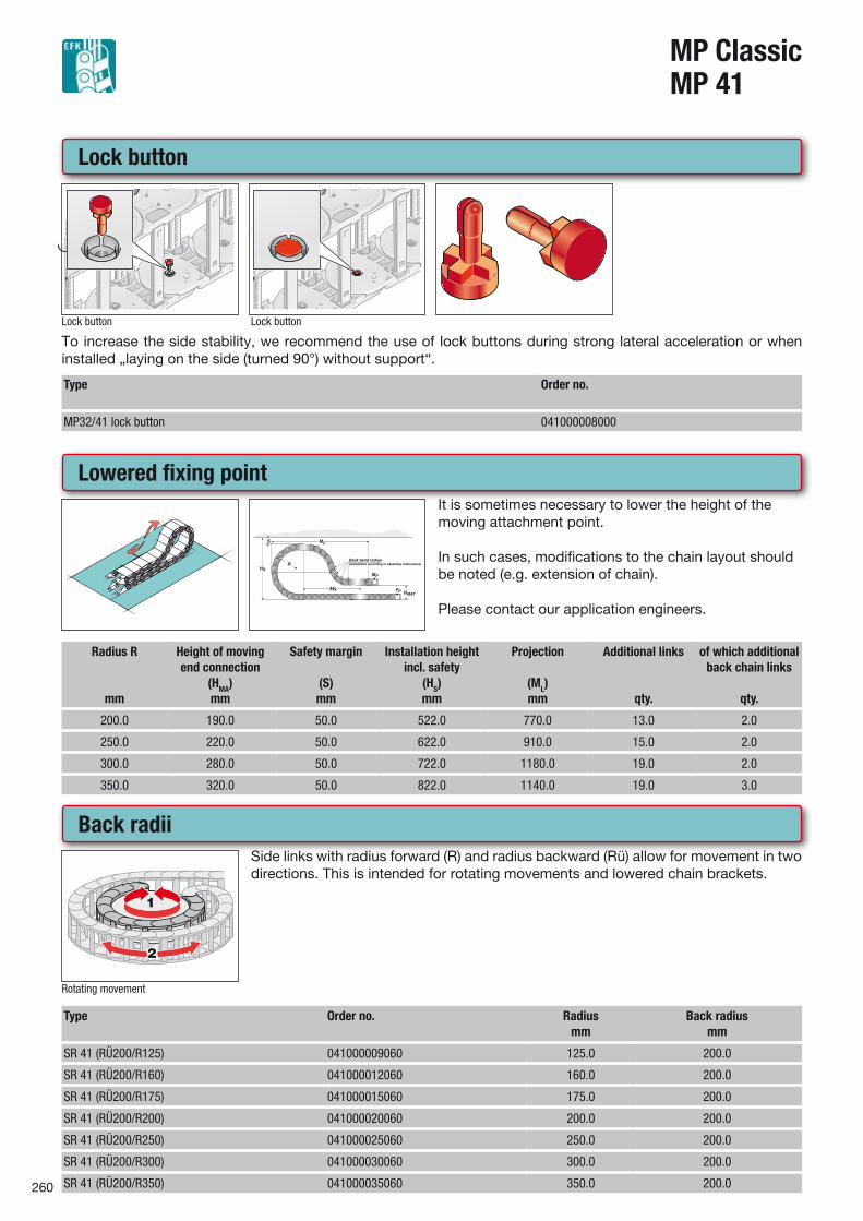
Back radii
Rotating movement
Side links with radius forward (R) and radius backward (Rü) allow for movement in two directions. This is intended for rotating movements and lowered chain brackets.
Type Order no. Radiusmm
Back radiusmm
SR 41 (RÜ200/R125) 041000009060 125.0 200.0
SR 41 (RÜ200/R160) 041000012060 160.0 200.0
SR 41 (RÜ200/R175) 041000015060 175.0 200.0
SR 41 (RÜ200/R200) 041000020060 200.0 200.0
SR 41 (RÜ200/R250) 041000025060 250.0 200.0
SR 41 (RÜ200/R300) 041000030060 300.0 200.0
SR 41 (RÜ200/R350) 041000035060 350.0 200.0
Lowered fixing pointIt is sometimes necessary to lower the height of the moving attachment point.
In such cases, modifications to the chain layout should be noted (e.g. extension of chain).
Please contact our application engineers.
Radius R
mm
Height of moving end connection
(HMA)mm
Safety margin
(S)mm
Installation height incl. safety
(HS)mm
Projection
(ML)mm
Additional links
qty.
of which additional back chain links
qty.
200.0 190.0 50.0 522.0 770.0 13.0 2.0
250.0 220.0 50.0 622.0 910.0 15.0 2.0
300.0 280.0 50.0 722.0 1180.0 19.0 2.0
350.0 320.0 50.0 822.0 1140.0 19.0 3.0
Lock button
Lock button
1.
Lock button
1.
To increase the side stability, we recommend the use of lock buttons during strong lateral acceleration or when installed „laying on the side (turned 90°) without support“.
Type Order no.
MP32/41 lock button 041000008000
261
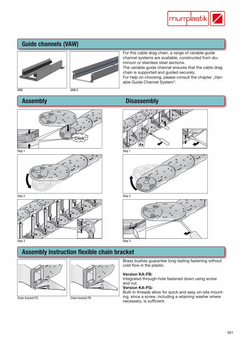
Guide channels (VAW)
VAW VAW-E
For this cable drag chain, a range of variable guide channel systems are available, constructed from alu-minium or stainless steel sections.The variable guide channel ensures that the cable drag chain is supported and guided securely. For help on choosing, please consult the chapter „Vari-able Guide Channel System“.
Guide channels (VAW) (Continued...)Assembly Disassembly
Step 1 Step 1
Step 2 Step 2
Step 3 Step 3
Assembly instruction flexible chain bracket
Chain bracket FG Chain bracket FB
Brass bushes guarantee long-lasting fastening without cold flow in the plastic.
Version KA-FB:Integrated through-hole fastened down using screw and nut.Version KA-FG:Built-in threads allow for quick and easy on-site mount-ing, since a screw, including a retaining washer where necessary, is sufficient.