1.- c280 epa tier 2 - imo ii marine project guide
TRANSCRIPT
7/23/2019 1.- c280 Epa Tier 2 - Imo II Marine Project Guide
http://slidepdf.com/reader/full/1-c280-epa-tier-2-imo-ii-marine-project-guide 1/222©2009 Caterpillar® All rights reserved.

7/23/2019 1.- c280 Epa Tier 2 - Imo II Marine Project Guide
http://slidepdf.com/reader/full/1-c280-epa-tier-2-imo-ii-marine-project-guide 2/222

7/23/2019 1.- c280 Epa Tier 2 - Imo II Marine Project Guide
http://slidepdf.com/reader/full/1-c280-epa-tier-2-imo-ii-marine-project-guide 3/222
©2012 Caterpillar® All rights reserved.
General ................................................................................ 1
Basic C280 Diesel Engine Design ................................................................ 1
C280 Diesel Engine Ratings ........................................................................ 2
Propulsion Engines ................................................................................ 2
Matching of Propellers and Waterjets ........................................................... 4
System Response ................................................................................. 5
Engine and Waterjet Tolerances .............................................................. 5
Waterjet Tolerances .............................................................................. 7
Technical Data ...................................................................... 9
C280 Technical Data Sheets ....................................................................... 9
Propulsion Data .................................................................................. 10
Auxiliary and Diesel Electric Propulsion Data .......................................... 45
Lubrication Oil System ........................................................ 61
General .................................................................................................. 61
Internal Lubrication System ...................................................................... 61
Oil Coolers ......................................................................................... 61
Thermostats ....................................................................................... 61
Oil Filters ........................................................................................... 61
Centrifugal Bypass Filters ..................................................................... 62
Oil Pumps .......................................................................................... 62
Lube Oil Heaters ................................................................................. 62
Prelubrication .......................................................................................... 62
Redundant Prelube System (recommended system) ................................. 62
Intermittent Prelube System ................................................................. 63
Continuous Prelube System .................................................................. 63
Postlubrication .................................................................................... 63
Generator Bearing Lube Oil System ............................................................ 63
Oil Requirements ..................................................................................... 64
Lubricant Viscosity ............................................................................. 64
Total Base Number (TBN)..................................................................... 64
Use of Commercial Oil ......................................................................... 64
Oil Change Interval .................................................................................. 64
Scheduled Oil Sampling ....................................................................... 65
Increasing Oil Change Intervals ............................................................. 65
Initial Oil Change Interval ..................................................................... 65
Change Interval without Oil Analysis Results .......................................... 65
7/23/2019 1.- c280 Epa Tier 2 - Imo II Marine Project Guide
http://slidepdf.com/reader/full/1-c280-epa-tier-2-imo-ii-marine-project-guide 4/222
©2012 Caterpillar® All rights reserved.
Inclination Capability ................................................................................ 65
Customer Piping Connections ................................................................... 66
Engine Connections ............................................................................. 66
Package Connections .......................................................................... 66
Lube Oil System Schematic ...................................................................... 66
Crankcase Ventilation System............................................. 68
Crankcase Emissions ............................................................................... 68
Crankcase Fumes Disposal ....................................................................... 68
Fuel System ....................................................................... 71
General .................................................................................................. 71
Internal Fuel System ................................................................................ 71
Fuel Transfer Pump ............................................................................. 71
Unit Injectors (EUI) .............................................................................. 71
External Fuel System Design Considerations ............................................... 71
Fuel Storage System ........................................................................... 71
Fuel Transfer System .......................................................................... 72
Fuel Filtration System .......................................................................... 72
Miscellaneous Fuel System Considerations ............................................. 72
Fuel Recommendations ............................................................................ 73
Customer Piping Connections ................................................................... 74
Fuel System Schematic ............................................................................ 74
Cooling System .................................................................. 75
General .................................................................................................. 75
Internal Cooling System ........................................................................... 75
Fresh Water Pumps ............................................................................. 75
External Cooling System Design Considerations .......................................... 75
Coolant Flow Control .......................................................................... 75
Coolant Temperature Control ............................................................... 77
Sea Water Pump (customer furnished) ................................................... 77
Expansion Tanks ................................................................................. 77
System Capacities .............................................................................. 77
Heat Exchangers ................................................................................. 78
Heat Exchanger Sizing ......................................................................... 78
Jacket Water Heaters .......................................................................... 79
System Pressures ............................................................................... 79
Venting ............................................................................................. 79
System Monitoring .............................................................................. 79

7/23/2019 1.- c280 Epa Tier 2 - Imo II Marine Project Guide
http://slidepdf.com/reader/full/1-c280-epa-tier-2-imo-ii-marine-project-guide 5/222
©2012 Caterpillar® All rights reserved.
Serviceability ...................................................................................... 79
System Pressures and Velocities ........................................................... 79
Heat Recovery ........................................................................................ 82
Water Maker ...................................................................................... 82
Generator Cooling ................................................................................... 82
Cooling Water Requirements ..................................................................... 82
Water Quality, Rust Inhibitors and Antifreeze ......................................... 82
Customer Piping Connections ................................................................... 83
Cooling System Schematics ...................................................................... 83
Starting Air System ............................................................ 97
General .................................................................................................. 97
Engine Starting Air System ....................................................................... 97
Starting Air System Design Considerations ................................................. 97
Air Supply Line Sizing ............................................................................ 101
Starting Air System Schematic................................................................ 102
Combustion Air System .................................................... 103
General ................................................................................................ 103
Combustion Air System Design Considerations ......................................... 103
Engine Room Supplied Air .................................................................. 103
Separate Combustion Air System ........................................................ 103
General ............................................................................................ 104
Combustion Air Piping System ................................................................ 105
Engine Room Ventilation ................................................... 108
General ................................................................................................ 108
Sizing Considerations ............................................................................. 108
Cooling Air ....................................................................................... 108
Combustion Air ................................................................................ 108
Ventilation Air Flow .......................................................................... 109
Engine Room Temperature ...................................................................... 109
Radiant Heat .................................................................................... 110
Calculating Required Ventilation Air Flow ............................................. 110
Ventilation Fans .................................................................................... 111
Fan Location .................................................................................... 111
Fan Type ......................................................................................... 111
Fan Sizing ........................................................................................ 111
Exhaust Fans ........................................................................................ 111
Two Speed Fan Motors ..................................................................... 112

7/23/2019 1.- c280 Epa Tier 2 - Imo II Marine Project Guide
http://slidepdf.com/reader/full/1-c280-epa-tier-2-imo-ii-marine-project-guide 6/222
©2012 Caterpillar® All rights reserved.
Routing Considerations .......................................................................... 112
1 and 2 Engine Applications ............................................................... 113
Ventilation Types 1 and 2 (Preferred Design) ........................................ 113
Ventilation Type 3 (Alternate Design) .................................................. 113
Ventilation Type 4 (Alternate Design) .................................................. 113
Multiple Engine (3+) Applications ....................................................... 115
Exhaust System ................................................................ 117
General ................................................................................................ 117
Exhaust System Design Considerations .................................................... 117
Exhaust Backpressure Limits .............................................................. 117
Turbochargers .................................................................................. 117
Exhaust Slobber (Extended Periods of Low Load) .................................. 117
Engine Operation at Idle or Low Load Conditions .................................. 118
Exhaust Piping .................................................................................. 118
Engine Piping Connections ...................................................................... 119
Exhaust Gas Piping System .................................................................... 119
Engine Governing and Control System .............................. 120
Introduction .......................................................................................... 120
Generator Engine Governing System ................................................... 120
Generator Engine Control System ....................................................... 120
Protection System PLC (MMS / GMS) ...................................................... 120
Features .......................................................................................... 120
PLC Monitoring System Options ......................................................... 124
Protection System ECP (Relay Based) ...................................................... 125
ECP Minimum Protection System (Accessory Module Mounted) .............. 125
ECP Complete Protection System (Accessory Module Mounted) ............. 126
ECP Maximum Protection System (Accessory module mounted) ............. 126
Other Optional Equipment (Not Control System Dependant) ................... 126
Other Optional Equipment (Main Components) ..................................... 127
Other Optional Equipment .................................................................. 128
Optional Marine Safety Requirements .................................................. 128
Optional Spare Part Kits ..................................................................... 128
Optional Engine Testing ..................................................................... 128
Optional Service Tools/Shipping Protection/Factory Support ................... 128
Optional Literature ............................................................................ 129
Engine Monitoring and Shutdown ..................................... 130
Engine Shutdown .................................................................................. 130
Engine Monitoring ................................................................................. 130

7/23/2019 1.- c280 Epa Tier 2 - Imo II Marine Project Guide
http://slidepdf.com/reader/full/1-c280-epa-tier-2-imo-ii-marine-project-guide 7/222
©2012 Caterpillar® All rights reserved.
Pressure Sensors .............................................................................. 130
Temperature Sensors ........................................................................ 130
Engine Control Panel ......................................................................... 130
Engine Mounting and Foundation Design ........................... 131
Propulsion Engine Mounting and Foundation ............................................. 131
C280 Engine Related Frequencies ............................................................ 132
Auxiliary Engine/Package Mounting and Foundation ................................... 133
Mounting ......................................................................................... 133
General ............................................................................................ 133
Generators ........................................................................................... 133
General ............................................................................................ 133
Miscellaneous .................................................................. 134
Engine Weights ..................................................................................... 134
C280 Genset Witness Test Description .................................................... 135
Performance Data: ............................................................................ 135
Electrical data: .................................................................................. 135
Pressures (kPa): ................................................................................ 135
Generator RTD: ................................................................................ 136
Temperatures (Deg C): ...................................................................... 136
General Information: .......................................................................... 136
Engine Data: .................................................................................... 136
Generator Data: ................................................................................ 136
Test Operation Data: ......................................................................... 136
Test Conditions: ............................................................................... 136
Maintenance Interval Schedule ................................................................ 137
Every Service Hour ........................................................................... 137
Daily ............................................................................................... 137
Every Week ...................................................................................... 137
Every 250 Service Hours ................................................................... 137
Every 250 Service Hours or 6 Weeks .................................................. 137
Every 500 Service Hours or 3 Months ................................................. 137
Initial 1000 Service Hours or 6 Months ............................................... 138
Every 1000 Service Hours or 6 Months ............................................... 138
Every 2000 Service Hours ................................................................. 138
Every 2000 Service Hours or 1 Year ................................................... 138
Every 4000 Service Hours or 1 Year ................................................... 138
Every 8000 Service Hours or 1 Year ................................................... 138
Every 8000 Service Hours or 3 Years .................................................. 139
Between 16,000 and 24,000 Service Hours ........................................ 139

7/23/2019 1.- c280 Epa Tier 2 - Imo II Marine Project Guide
http://slidepdf.com/reader/full/1-c280-epa-tier-2-imo-ii-marine-project-guide 8/222
©2012 Caterpillar® All rights reserved.
Every 16,000 Service Hours or 6 Years ............................................... 139
Between 36,000 and 44,000 Service Hours ........................................ 139
Storage Preservation Specification ........................................................... 140
Preservation Procedures .................................................................... 140
General Arrangement Drawings ........................................ 142
C280-Diesel Engine General Arrangement Drawings .................................. 142
C280-6 Engine Only .......................................................................... 142
C280-8 Engine Only .......................................................................... 151
C280-12 Engine Only ........................................................................ 159
C280-16 Engine Only ........................................................................ 167
C280-16 Front Mounted Turbocharger Engine ...................................... 176
C280-16 Front Mounted Turbocharger Genset ..................................... 181
C280-6 Genset ................................................................................. 187
C280-12 Genset ............................................................................... 191
C280-16 Genset ............................................................................... 193
Shipped Loose Items ......................................................................... 199
Optional Items .................................................................................. 201
Lifting Schematic .............................................................................. 205
Inline Engines Removal Distances ....................................................... 206
Vee Engines Removal Distances ......................................................... 207
Typical Supplied Auxiliary Equipment ....................................................... 209
Reference Material ........................................................... 211

7/23/2019 1.- c280 Epa Tier 2 - Imo II Marine Project Guide
http://slidepdf.com/reader/full/1-c280-epa-tier-2-imo-ii-marine-project-guide 9/222
©2012 Caterpillar® All rights reserved. 1
G E N E R A L
General
Basic C280 Diesel Engine DesignThe C280 Engine Family for marine applications is a modern, highly efficient, IMO
certified engine series consisting of in-line engines of 6 and 8 cylinders and veeengines of 12 and 16 cylinders. These are four stroke, non-reversible engines ratedat speeds from 900 to 1000 rpm and intended for use as main propulsion andelectric power generator drivers for marine applications. The engines areturbocharged, charge air cooled and with a direct injection fuel system using unitfuel injectors. The use of individual fuel injectors eliminates the need for highpressure piping and provides for an accurate, high injection pressure.
The engine block is a nodular cast iron block. The intake plenum runs the fulllength of the engine, providing even air distribution to the cylinders.
The crankshaft is a pressed forging that is induction hardened. A counter-weight
for each cylinder is bolted to the crankshaft using a robust 3 bolt design.Crankshaft end flanges are identical so full power can be taken off from either end.
The main, rod and camshaft bearings are steel-backed, nickel bonded aluminumwith a lead-tin overlay, copper-bonded to the aluminum. Experience has shown thisproduces the best bearing construction available for the longest possible life.
The connecting rods are forged, heat treated and shot peened before machining.The special four-bolt design allows for an extra-large bearing which reduces bearingload and extends bearing life.
The cylinder liners are high alloy iron castings, induction hardened, plateau honedand water jacketed over their full length. The liners are equipped with an anti-
polishing ring (cuff) to avoid piston / liner carbonizing and thus improve lube oilcontrol and liner life.
The pistons are two-piece with a steel crown and forged aluminum skirt forexcellent strength and durability, yet light weight. Each piston has four rings, twoin hardened grooves in the crown and two in the skirt. The top compression ring isasymmetrically faced with a chrome-ceramic matrix coating to provide extendedring and liner life. The two middle rings are taper-faced and chrome plated, whilethe lower lube oil control ring is double rail chrome faced, with a spring expander.Oil is jet sprayed into passageways within the pistons for cooling and lubrication ofthe piston pin.
The valve seats on the replaceable inserts are induction-hardened. Positiverotators on all the valves maintain a uniform temperature and wear pattern acrossthe valve face and seat. The exhaust and air inlet valves are both manufacturedfrom Nimonic 80A material.
The cooling system can either be combined circuit or separate circuit, dependingon emissions levels and available sea water temperature. Both versions use twoidentical centrifugal pumps to get coolant (usually a 50/50 water/glycol mix) to theaftercooler, oil cooler, block, and heads. Orifices are used to ensure correct coolant

7/23/2019 1.- c280 Epa Tier 2 - Imo II Marine Project Guide
http://slidepdf.com/reader/full/1-c280-epa-tier-2-imo-ii-marine-project-guide 10/222
C28
MARINE PROJECT GUIDE
©2012 Caterpillar® All rights reserved.2
G E N E R A L
flow to each component. There is an optional connection for a jacket water heaterif required to meet cold-starting applications.
The air starting system is highly reliable turbine driven air motor that does notcontain rubbing parts and does not required external lubrication.
The engine mounting system is a robust system of mounting feet that enableproper support to the installation foundation and top plate(s). The C280-6 andC280-8 are designed with four mounting feet and the C280-12 and C280-16 usesix mounting feet.
C280 Diesel Engine Ratings
Propulsion Engines
Continuous Service Ratings (CSR) – Marine Diesel Oil
Engine Model C280-6 C280-8
Rated Speed (rpm) 900 1000 900 1000
Rated Power (bkW) 1730 1850 2300 2460
Rated Power (bhp) 2320 2481 3084 3299
Rated Power (mhp) 2352 2515 3127 3345
Max. air temp. to turbocharger – °C (°F)
Max. aftercooler inlet water temp. – °C (°F)
Aftercooler temperature for sizing – °C (°F)** 32 oC (90 oF)
Engine Model C280-12 C280-16
Rated Speed (rpm) 900 1000 900 1000
Rated Power (bkW) 3460 3700 4600 4920
Rated Power (bhp) 4640 4962 6169 6598
Rated Power (mhp) 4704 5031 6255 6690
Max. air temp. to turbocharger – °C (°F)
Max. aftercooler inlet water temp. – °C (°F)**
Aftercooler temperature for sizing – °C (°F)** 32 oC (90 oF)
The above ratings are based on the following approximate load profile:
• 100% of the engine operating hours at 100% of rated power.
These ratings correspond to the ISO 3046 Fuel Stop Power definitions.
These ratings can also be used for AUX, DEP Continuous Ratings.
** See Heat Exchanger Sizing Chart for C280 engines on page 78.
7/23/2019 1.- c280 Epa Tier 2 - Imo II Marine Project Guide
http://slidepdf.com/reader/full/1-c280-epa-tier-2-imo-ii-marine-project-guide 11/222
©2012 Caterpillar® All rights reserved. 3
G E N E R A L
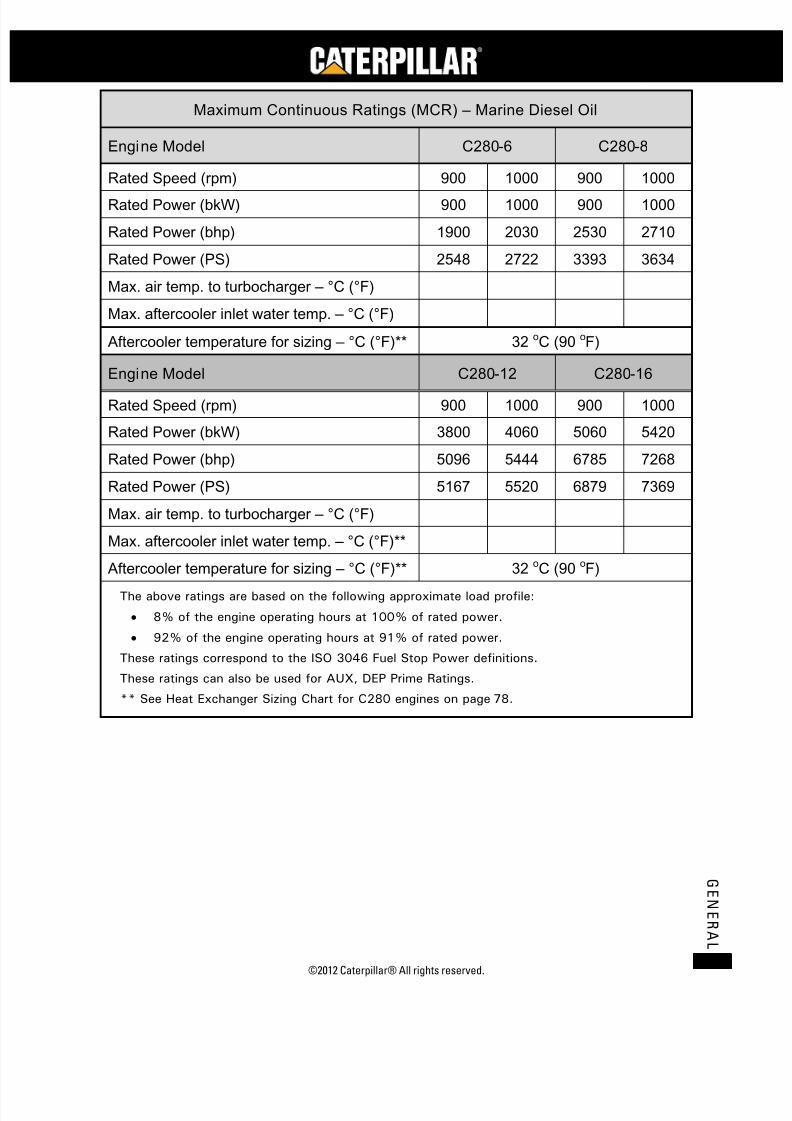
Maximum Continuous Ratings (MCR) – Marine Diesel Oil
Engine Model C280-6 C280-8
Rated Speed (rpm) 900 1000 900 1000
Rated Power (bkW) 900 1000 900 1000
Rated Power (bhp) 1900 2030 2530 2710
Rated Power (PS) 2548 2722 3393 3634
Max. air temp. to turbocharger – °C (°F)
Max. aftercooler inlet water temp. – °C (°F)
Aftercooler temperature for sizing – °C (°F)** 32 oC (90 oF)
Engine Model C280-12 C280-16
Rated Speed (rpm) 900 1000 900 1000
Rated Power (bkW) 3800 4060 5060 5420
Rated Power (bhp) 5096 5444 6785 7268
Rated Power (PS) 5167 5520 6879 7369
Max. air temp. to turbocharger – °C (°F)
Max. aftercooler inlet water temp. – °C (°F)**
Aftercooler temperature for sizing – °C (°F)** 32 oC (90 oF)
The above ratings are based on the following approximate load profile:
• 8% of the engine operating hours at 100% of rated power.
• 92% of the engine operating hours at 91% of rated power.
These ratings correspond to the ISO 3046 Fuel Stop Power definitions.
These ratings can also be used for AUX, DEP Prime Ratings.
** See Heat Exchanger Sizing Chart for C280 engines on page 78.

7/23/2019 1.- c280 Epa Tier 2 - Imo II Marine Project Guide
http://slidepdf.com/reader/full/1-c280-epa-tier-2-imo-ii-marine-project-guide 12/222
C28
MARINE PROJECT GUIDE
©2012 Caterpillar® All rights reserved.4
G E N E R A L
Commercial Fast Vessel Ratings – Marine Diesel Oil
Engine Model C280-16
Rated Speed (rpm) 1000
Rated Power (bkW) 5650
Rated Power (bhp) 7577
Rated Power (PS) 7682
Max. air temp. to turbocharger – °C (°F) 45 oC (113 oF)
Max. aftercooler inlet water temp. – °C (°F) ** 38 oC (100 oF)
The above ratings are based on the following approximate load profile:
• 85% of the engine operating hours at 100% of rated power.
• 15% of the engine operating hours at less than 50% of rated power.
These ratings correspond to the ISO 3046 Fuel Stop Power definitions.
** See Heat Exchanger Sizing Chart for C280 engines on page 78.
Ratings are based on ISO 3046/1 and SAE J1995 standard reference conditionsof 100 kPa (30 in. Hg), 25°C (77°F), and 30% relative humidity at the statedcharge air cooler water temperature.
Performance and fuel consumption based on 35 API, 16°C (61°F) fuel used @29°C (84°F) with a density of 838.9 g/l (7.001 lbs/U.S. gal). Lower heat value offuel 42 750 kJ/kg (18,380 btu/lb).
Ratings meet the classification society maximum requirements of 45°C (113°F)to the air inlet of the turbocharger and 32°C (100°F) sea water temperaturewithout derate, unless otherwise stated.
Matching of Propellers and WaterjetsControllable Pitch (CP) propellers are normally designed so that 90 to 100% of
the rated power is utilized when the ship is on trial at a specified speed and load.Overload protection or load control is necessary to protect the engine from
overload in the event of heavy vessel loading weather conditions, sea state, or hullfouling.
Waterjets approximate a fixed pitch propeller demand curve and can also beaffected by vessel loading, weather conditions, sea state, and hull fouling. Thewaterjet power demand should be matched such that these conditions do not resultin engine overload. The waterjet to engine match should be based on expectedheavy ship conditions, propulsion system power losses, reduction gear losses, etc.
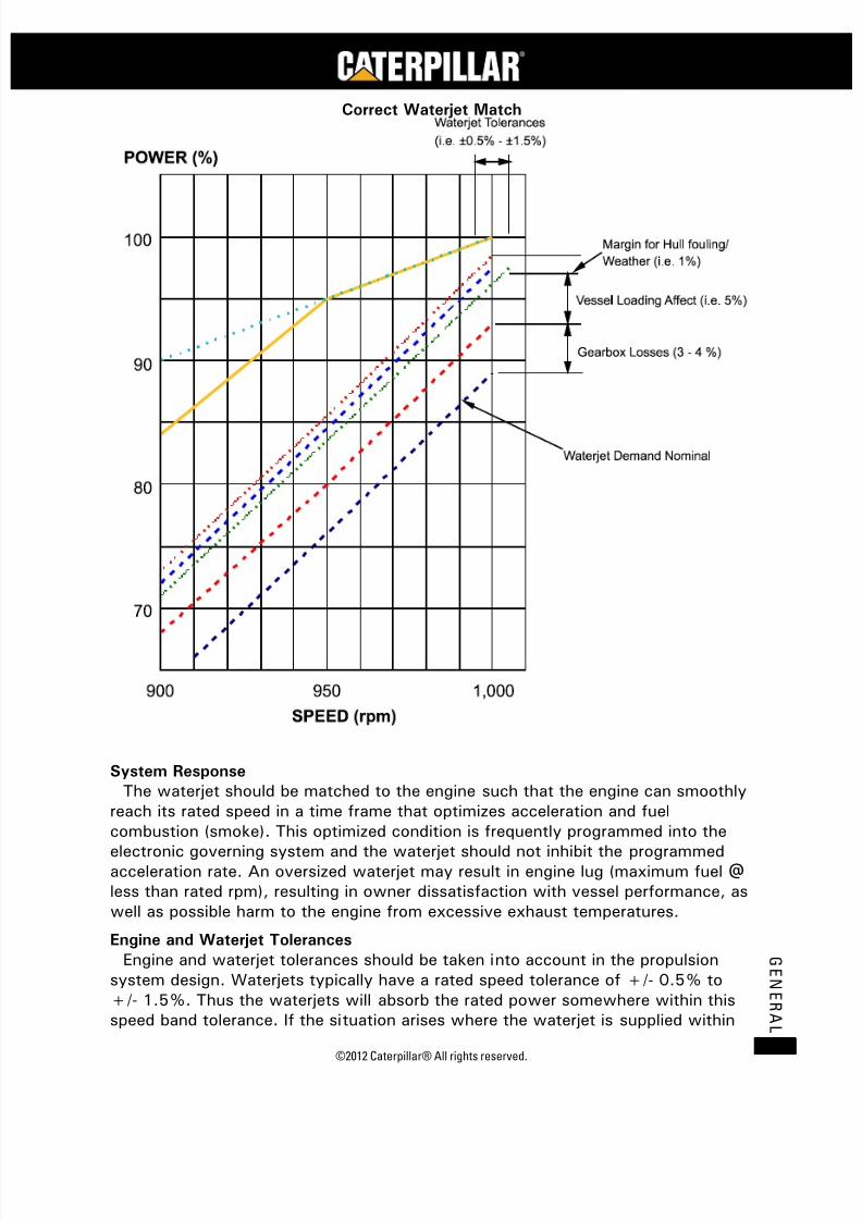
The following graph provides an example of a correct waterjet match.
7/23/2019 1.- c280 Epa Tier 2 - Imo II Marine Project Guide
http://slidepdf.com/reader/full/1-c280-epa-tier-2-imo-ii-marine-project-guide 13/222
©2012 Caterpillar® All rights reserved. 5
G E N E R A L
Correct Waterjet Match
System Response
The waterjet should be matched to the engine such that the engine can smoothlyreach its rated speed in a time frame that optimizes acceleration and fuelcombustion (smoke). This optimized condition is frequently programmed into theelectronic governing system and the waterjet should not inhibit the programmedacceleration rate. An oversized waterjet may result in engine lug (maximum fuel @less than rated rpm), resulting in owner dissatisfaction with vessel performance, aswell as possible harm to the engine from excessive exhaust temperatures.
Engine and Waterjet Tolerances
Engine and waterjet tolerances should be taken into account in the propulsionsystem design. Waterjets typically have a rated speed tolerance of +/- 0.5% to+/- 1.5%. Thus the waterjets will absorb the rated power somewhere within thisspeed band tolerance. If the situation arises where the waterjet is supplied within

7/23/2019 1.- c280 Epa Tier 2 - Imo II Marine Project Guide
http://slidepdf.com/reader/full/1-c280-epa-tier-2-imo-ii-marine-project-guide 14/222
C28
MARINE PROJECT GUIDE
©2012 Caterpillar® All rights reserved.6
G E N E R A L
these specifications, but at the lower limit of the speed tolerance, it could meanthat the propeller demand would require 4.5% more power at the nominal ratedspeed. If the waterjet is supplied with the ability to absorb the power only at theupper limit of the speed tolerance, the engine may not be able to pull the ratedpower out of the waterjet, as the engine may not be able to operate at this higher
rpm. The C280 tolerances provide nominal power +/- 1.5% with a rated speedtolerance of + 0.5% to – 1.0%. To insure the best possible match between theengine and the waterjet in view of the tolerance differences, the followingprocedure applies.
Engine adjustment and acceptability guidelines for sea trials:
1. If the maximum engine speed in the ship installation during full load sea trialsis between 995 rpm and 1000 rpm, no adjustments will be made to theengine settings.
2. If the maximum engine speed in the ship installation during full load sea trialsis 1000 rpm and the shipyard measured parameters such as boost, fuel rate,
rack position and/or cylinder pressure indicate that between 1001 and 1005rpm is necessary to achieve the rated power, no adjustments will be made tothe engine settings.
3. If the maximum engine speed in the ship installation during full load sea trialsis between 990 rpm and 994 rpm and the shipyard parameters indicate thatthe engine is in the lower end of the power tolerance, the rack setting can beincreased so that the minimum power will be within -1.5% tolerance (2670bkW in the case of the 2710 bkW rating) based on standard ambientconditions. A new specification will be created to reflect the new racksetting and a new engine nameplate will be stamped.
4. If the maximum engine speed in the ship installation during full load sea trialsis 1000 rpm and the shipyard measured parameters indicate that between1006 rpm and 1010 rpm is necessary to achieve the rated power, the enginerated speed may be increased. The engine rated speed will not exceed 1010rpm and Caterpillar reserves the option of reducing fuel stop setting toprovide a maximum output of 2750 bkW at standard conditions within the1006-1010 rpm speed range. If necessary, a new specification will becreated to reflect the new rack setting and a new nameplate will bestamped.
5. A maximum attainable engine speed of less than 990 rpm is considered
unacceptable for lug for continuous operation.
Requirements / Conditions:
1. The dynamometer test results at fuel stop power will be used as the criteriafor evaluating installed engine power.
2. ISO standard reference conditions apply for power, not site conditions.
3. Minimum power setting (no negative tolerance in the dyno) will be driven bythe quoter including the associated additional cost.
4. The minimum tolerance on engine power in the dyno will be reduced to 2%.

7/23/2019 1.- c280 Epa Tier 2 - Imo II Marine Project Guide
http://slidepdf.com/reader/full/1-c280-epa-tier-2-imo-ii-marine-project-guide 15/222
©2012 Caterpillar® All rights reserved. 7
G E N E R A L
5. A tolerance of +/- 1.5% applies to engine power in the field based onstandard conditions.
6. The standard rated power and speed will not be changed on the newnameplate, only the rack setting.
Note: The nominal propeller demand curve shown in the C280-8 Power and SpeedTolerances Graph shows the cubic demand curve through the engine design pointof 2710 bkW at 1000 rpm. The propeller demand curves 2 and 3 are matchedthrough the minimum and maximum power tolerance limits at rated speed.
C280-8 Power and Speed Tolerances
Waterjet Tolerances
Standard waterjet tolerances are +/- 1.5% speed at rated power. This speedtolerance is a function of the pump design, hull form, vessel speed and waterjet
intake design. The engine speed tolerance at rated power is less than the waterjettolerance (+0.5%/-1.0% versus +/- 1.5%). This means there is a possibility forthe waterjet to be oversized or undersized if the maximum minus or plus speedtolerance on the water jet is obtained at rated power.
An oversized waterjet will cause the engine to operate at fuel stop rack (lug)when the engine is set for the rated 2710 bkW at 1000 rpm. The engine speedmay be less than the minimum 990 rpm (-1.0% engine speed tolerance) required toobtain power within the minus tolerance band with factory rack setting. The enginecan operate in lug continuously down to 980 rpm. However, the engine poweroutput will be out of the minus tolerance band.

7/23/2019 1.- c280 Epa Tier 2 - Imo II Marine Project Guide
http://slidepdf.com/reader/full/1-c280-epa-tier-2-imo-ii-marine-project-guide 16/222
C28
MARINE PROJECT GUIDE
©2012 Caterpillar® All rights reserved.8
G E N E R A L
An undersized waterjet will prevent the engine from reaching rated power at therated 1000 rpm. Engine speed may be increased to a maximum of 1015 rpm butpower output may still be below the minimum tolerance of 2670 bkW with thefactory rack setting. The rack setting may be changed to achieve a maximumoutput of 2750 bkW at standard ambient conditions at 1015 rpm.
To minimize the possibility of a significantly oversized waterjet, the customerand/or jet manufacturer may choose to use a different nominal jet sizing point thanthe rated engine operating point (2710 bkW at 1000 rpm). By choosing a lowernominal water jet rating at 1000 rpm, the jet speed tolerance band may be made tofall entirely within the engine limits such that continuous lug operation is notpossible.

7/23/2019 1.- c280 Epa Tier 2 - Imo II Marine Project Guide
http://slidepdf.com/reader/full/1-c280-epa-tier-2-imo-ii-marine-project-guide 17/222
©2012 Caterpillar® All rights reserved. 9
T E C H N I C A L D A T A
Technical Data
C280 Technical Data SheetsThe following Technical Data Sheets represent the latest available C280 engine
series technical information at the time of publication and are subject to change.Consult with a Caterpillar dealer to obtain the most current data.
7/23/2019 1.- c280 Epa Tier 2 - Imo II Marine Project Guide
http://slidepdf.com/reader/full/1-c280-epa-tier-2-imo-ii-marine-project-guide 18/222
C28
MARINE PROJECT GUIDE
©2012 Caterpillar® All rights reserved.10
T E C H N I C A L D A T A
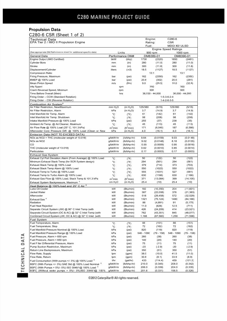
Propulsion Data
C280-6 CSR (Sheet 1 of 2)
bkW (bhp) (2320) 1850 (2481)
mm (in) (11.0) 280 (11.0)
mm (in) (11.8) 300 (11.8)
liters (in3) (1127) 18.5 (1127)
bar (psi) (2350) 162 (2350)
bar (psi) (302) 20.0 (291)
m/s (ft/s) (29.5) 10.0 (32.8)
mm H2O (in H2O) (5/15) 125/380 (5/15)
kPa (in H2O) (14.9) 3.7 (14.9)oC (
oF) (142) 61 (142)
oC (
oF) (208) 98 (208)
kPa (psi) (37) 238 (35)oC (
oF) (113) 45 (113)
m3/min (ft
3/min) (6,049) 187 (6,586)
kPa (in H2O) (16.1) 4.0 (16.1)
g/bkW-hr (lb/bhp-hr) (0.0159) 9.03 (0.0148)
g/bkW-hr (lb/bhp-hr) (0.0148) 8.18 (0.0135)
g/bkW-hr (lb/bhp-hr) (0.0009) 0.95 (0.0016)
g/bkW-hr (lb/bhp-hr) (0.0010) 0.85 (0.0014)
g/bkW-hr (lb/bhp-hr) (0.0003) 0.17 (0.0003)
oC (
oF) (122) 50 (122)
oC (
oF) (561) 294 (561)
o
C (o
F) (714) 373 (703)oC (
oF) (1022) 550 (1022)
oC (
oF) (1031) 527 (981)
oC (
oF) (1166) 630 (1166)
m3/min (ft
3/min) (13,084) 399 (14,105)
cm H2O (in H2O) (10) 25.4 (10)
kW (Btu/min) (10,350) 204 (11,601)
kW (Btu/min) (22,008) 376 (21,383)
kW (Btu/min) (29,458) 572 (32,529)
kW (Btu/min) (75,124) 1480 (84,166)
kW (Btu/min) (4,891) 91 (5,175)
kW (Btu/min) (626) 12.5 (711)
kW (Btu/min) (24,209) 414 (23,521)
kW (Btu/min) (43,351) 845 (48,077)
kW (Btu/min) (67,560) 1,259 (71,598)
oC (
oF) (151) 66 (151)
oC (
oF) (162) 72 (162)
kPa (psi) (119) 820 (119)
kPa (psi) (79 - 158) 546 - 1090 (79 - 158)
kPa (psi) (38) 260 (38)
kPa (psi) (20) 140 (20)
kPa (psi) (11) 75 (11)
kPa (psi) (-2.9) -20 (-2.9)
kPa (psi) (51) 350 (51)
lpm (gpm) (10.0) 41.5 (11.0)
lpm (gpm) (8.1) 33.9 (8.9)
l/hr (gal/hr) (114.4) 459 (121.2)
g/bkW-hr (lb/bhp-hr) (0.345) 208.0 (0.342)
g/bkW-hr (lb/bhp-hr) (0.339) 204.0 (0.335)
g/bkW-hr (lb/bhp-hr) (0.331) 198.5 (0.326)
Technical Data Engine: C280-6
EPA Tier 2 / IMO II Propulsion Engine Rating: CSR
Fuel: MDO/ #2/ ULSD
Engine Speed Ratings(See appropr iate DM Performance sheet for additional specif ic data) Units 900 rpm 1000 rpm
General Data Performance DM# DM8389-01 DM8390-01Engine Output (IMO Certified) 1730
Cylinder Bore 280
Stroke 300
Displacement/Cylinder 18.5
Compression Ratio 13:1 13:1
Firing Pressure, Maximum 162
BMEP @ 100% Load 20.8
Mean Piston Speed 9.0
Idle Speed rpm 350 350
Crash Reversal Speed, Minimum rpm 300 300
Time Before Overall (Main) hrs 36,000 - 44,000 36,000 - 44,000
Firing Order – CCW (Standard Rotation) 1-5-3-6-2-4
Firing Order – CW (Reverse Rotation) 1-4-2-6-3-5
Combustion Air System6
Air Filter Restriction, New/Maximum 125/380
Air Filter Restriction, Alarm 3.7Inlet Manifold Air Temp. Alarm 61
Inlet Manifold Air Temp. Shutdown 98
Intake Manifold Pressure @ 100% Load 255
Ambient Air Temp. @ Air Cleaner, Maximum 45
Air Flow Rate @ 100% Load (25° C, 101.3 kPa) 171
Aftercooler Core Pressure Diff. @ 100% Load (Clean or New 4.0
Emiss ion Data (NOT TO EXCEED DATA)
NOx as NO2 + THC (molecular weight of 13.018) 9.64
NOx as NO2 9.02
CO 0.55
THC (molecular weight of 13.018) 0.62
Particulates 0.17
Exhaust Gas System
Exhaust Cyl Port Deviation Alarm (From Average) @ 100% Load 50
Minimum Exhaust Stack Temp (for SCR System design) 294
Exhaust Stack Temp @ 100% Load 379Exhaust Stack Temp Alarm @ 100% Load 550
Exhaust Temp to Turbo @ 100% Load 555
Exhaust Temp to Turbo Alarm @ 100% Load 630
Exhaust Gas Flow @ 100% Load, Stack Temp & 101.3 kPa 371
Exhaust System Backpressure, Maximum3 25.4
Heat Balance @ 100% load and 25° C Air6
Lube Oil Cooler 182
Jacket Water 387
Aftercooler 518
Exhaust Gas4 1321
Radiation 86
Fuel Heat Rejection 11.0
Separate Circuit System (JW) @ 90° C Inlet Temp (with 426
Separate Circuit System (OC & AC) @ 32° C Inlet Temp (with 762
Combined Circuit System (JW, OC & AC) @ 32° C Inlet (with 1,188
Fuel SystemFuel Temperature, Alarm 66
Fuel Temperature, Stop 72
Fuel Manifold Pressure Nominal @ 100% Load 820
Fuel Manifold Pressure Range @ 100% Load 546 - 1090
Fuel Pressure, Alarm > 650 rpm 260
Fuel Pressure, Alarm < 650 rpm 140
Fuel Filter Differential Pressure, Alarm 75
Pump Suction Restriction, Maximum -20
Return Line Backpressure, Maximum 350
Flow Rate, Supply 38.0
Flow Rate, Return 30.8
Fuel Consumption (With pumps +/- 3%) @ 100% Load5 433
BSFC (With Pumps +/- 3%) SAE Std @ 100% Load Nominal5 210.0
BSFC (With Pumps + 5%/- 0%) ISO 3046/1@ 100% Load5 206.0
BSFC (Without water pumps + 5%/- 0%)ISO 3046/1@ 100%
201.6

7/23/2019 1.- c280 Epa Tier 2 - Imo II Marine Project Guide
http://slidepdf.com/reader/full/1-c280-epa-tier-2-imo-ii-marine-project-guide 19/222
©2012 Caterpillar® All rights reserved. 11
T E C H N I C A L D A T A
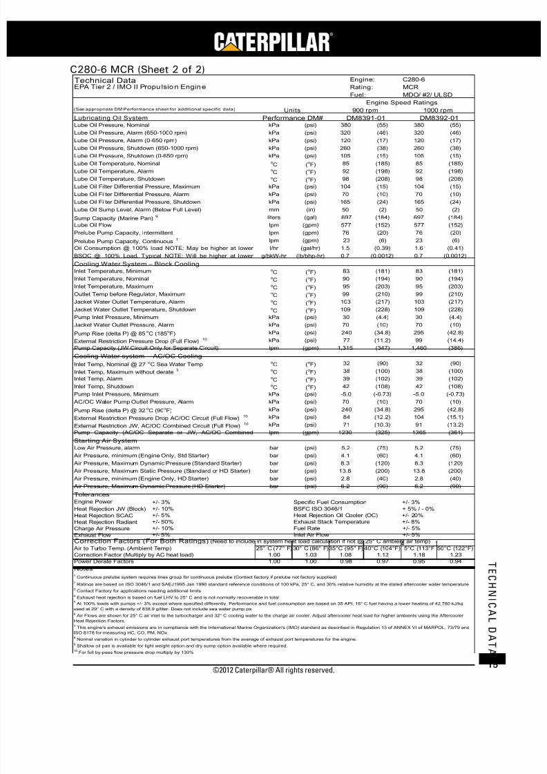
C280-6 CSR (Sheet 2 of 2)
kPa (psi) (55) 380 (55)
kPa (psi) (46) 320 (46)kPa (psi) (17) 120 (17)
kPa (psi) (38) 260 (38)
kPa (psi) (15) 105 (15)oC (
oF) (185) 85 (185)
oC (
oF) (198) 92 (198)
oC (
oF) (208) 98 (208)
kPa (psi) (15) 104 (15)
kPa (psi) (10) 70 (10)
kPa (psi) (24) 165 (24)
mm (in) (2) 50 (2)
liters (gal) (184) 697 (184)
lpm (gpm) (152) 577 (152)
lpm (gpm) (20) 76 (20)
lpm (gpm) (6) 23 (6)
l/hr (gal/hr) (0.35) 1.4 (0.38)
g/bkW-hr (lb/bhp-hr) (0.0012) 0.7 (0.0012)
oC (
oF) (181) 83 (181)
oC (
oF) (194) 90 (194)
oC (
oF) (203) 95 (203)
oC (
oF) (210) 99 (210)
oC (
oF) (217) 103 (217)
oC (
oF) (228) 109 (228)
kPa (psi) (4.4) 30 (4.4)
kPa (psi) (10) 70 (10)
kPa (psi) (34.8) 295 (42.8)
kPa (psi) (11.2) 99 (14.4)
lpm (gpm) (347) 1,460 (386)
oC (
oF) (90) 32 (90)
oC (
oF) (100) 38 (100)
oC (
oF) (102) 39 (102)
oC (
oF) (108) 42 (108)
kPa (psi) (-0.73) -5.0 (-0.73)
kPa (psi) (10) 70 (10)
kPa (psi) (34.8) 295 (42.8)
kPa (psi) (12.2) 104 (15.1)
kPa (psi) (10.3) 91 (13.2)
lpm (gpm) (325) 1365 (361)
bar (psi) (75) 5.2 (75)
bar (psi) (60) 4.1 (60)
bar (psi) (120) 8.3 (120)
bar (psi) (200) 13.8 (200)
bar (psi) (40) 2.8 (40)
bar (psi) (90) 6.2 (90)
Engine Power +/- 3%
Heat Rejection JW (Block) +/- 10%
Heat Rejection SCAC +/- 5%
Heat Rejection Radiant +/- 50%
Charge Air Pressure +/- 10%
Exhaust Flow +/- 5%
25° C (77° F)30° C (86° F) 40°C (104°F) 5°C (113°F 50°C (122°F)
1.00 1.03 1.13 1.18 1.23
1.00 1.00 0.97 0.95 0.94
8 Normal variation in cylinder to cylinder exhaust port temperatures from the average of exhaust port temperatures for the engine.
9 Shallow oil pan is available for light weight option and dry sump option available where required.
10 For full by-pass flow pressure drop multiply by 130%
4 Exhaust heat rejection is based on fuel LHV to 25° C and is not normally recoverable in total
5 At 100% loads with pumps +/- 3% except where specified differently. Performance and fuel consumption are based on 35 API, 16° C fuel having a lower heating of 42,780 kJ/kg
used at 29° C with a density of 838.9 g/liter. Does not include sea water pump pa6 Air Flows are shown for 25° C air inlet to the turbocharger and 32° C cooling water to the charge air cooler. Adjust aftercooler heat load for higher ambients using the Aftercooler
Heat Rejection Factors.7 This engine's exhaust emissions are in compliance with the International Marine Organization's (IMO) standard as described in Regulation 13 of ANNEX VI of MARPOL, 73/79 and
ISO 8178 for measuring HC, CO, PM, NOx.
Notes1 Continuous prelube system requires lines group for continuous prelube (Contact factory if prelube not factory supplied)
2 Ratings are based on ISO 3046/1 and SAEJ1995 Jan 1990 standard reference conditions of 100 kPa, 25° C, and 30% relative humidity at the stated aftercooler water temperature
3 Contact Factory for applications needing additional limits
Correction Factor (Multiply by AC heat load) 1.08
Power Derate Factors 0.98
Inlet Air Flow +/- 5%Correction Factors (For Both Ratings) (Need to include in system heat load calculation if not @ 25° C ambient air temp)
Air to Turbo Temp. (Ambient Temp) 35°C (95° F)
Exhaust Stack Temperature +/- 8%
Fuel Rate +/- 5%
BSFC ISO 3046/1 + 5% / - 0%
Heat Rejection Oil Cooler (OC) +/- 20%
Air Pressure, Maximum Dynamic Pressure (HD Starter) 6.2
Tolerances
Specific Fuel Consumption +/- 3%
Air Pressure, Maximum Static Pressure (Standard or HD Starter) 13.8
Air Pressure, minimum (Engine Only, HD Starter) 2.8
Air Pressure, minimum (Engine Only, Std Starter) 4.1
Air Pressure, Maximum Dynamic Pressure (Standard Starter) 8.3
Pump Capacity (AC/OC Separate or JW, AC/OC Combined 1230
Starting Air System
Low Air Pressure, alarm 5.2
External Restriction Pressure Drop AC/OC Circuit (Full Flow)10 84
External Restriction JW, AC/OC Combined Circuit (Full Flow)10 71
AC/OC Water Pump Outlet Pressure, Alarm 70
Pump Rise (delta P) @ 32oC (90
oF) 240
Inlet Temp, Shutdown 42
Pump Inlet Pressure, Minimum -5.0
Inlet Temp, Maximum without derate3 38
Inlet Temp, Alarm 39
Pump Capacity (JW Circuit Only for Separate Circuit) 1,315
Cooling Water system – AC/OC Cooling
Inlet Temp, Nominal @ 27oC Sea Water Temp 32
Pump Rise (delta P) @ 85oC (185
oF) 240
External Restriction Pressure Drop (Full Flow)10 77
Pump Inlet Pressure, Minimum 30
Jacket Water Outlet Pressure, Alarm 70
Jacket Water Outlet Temperature, Alarm 103
Jacket Water Outlet Temperature, Shutdown 109
Inlet Temperature, Maximum 95
Outlet Temp before Regulator, Maximum 99
Cooling Water System – Block CoolingInlet Temperature, Minimum 83
Inlet Temperature, Nominal 90
Oil Consumption @ 100% load NOTE: May be higher at lower 1.3
BSOC @ 100% Load, Typical NOTE: Will be higher at lower 0.7
Prelube Pump Capacity, Intermittent 76
Prelube Pump Capacity, Continuous1 23
Sump Capacity (Marine Pan)9 697
Lube Oil Flow 577
Lube Oil Filter Differential Pressure, Shutdown 165
Lube Oil Sump Level, Alarm (Below Full Level) 50
Lube Oil Filter Differential Pressure, Maximum 104
Lube Oil Filter Differential Pressure, Alarm 70
Lube Oil Temperature, Alarm 92
Lube Oil Temperature, Shutdown 98
Lube Oil Pressure, Shutdown (0-650 rpm) 105
Lube Oil Temperature, Nominal 85
Lube Oil Pressure, Alarm (0-650 rpm) 120
Lube Oil Pressure, Shutdown (650-1000 rpm) 260
Lube Oil Pressure, Nominal 380
Lube Oil Pressure, Alarm (650-1000 rpm) 320
Lubricating Oil System Performance DM# DM8389-01 DM8390-01
(See appropriate DM Performance sheet for additional specific data) Units 900 rpm 1000 rpm
Fuel: MDO/ #2/ ULSD
Engine Speed Ratings
Technical Data Engine: C280-6
EPA Tier 2 / IMO II Propulsi on Engine Rating: CSR

7/23/2019 1.- c280 Epa Tier 2 - Imo II Marine Project Guide
http://slidepdf.com/reader/full/1-c280-epa-tier-2-imo-ii-marine-project-guide 20/222
C28
MARINE PROJECT GUIDE
©2012 Caterpillar® All rights reserved.12
T E C H N I C A L D A T A
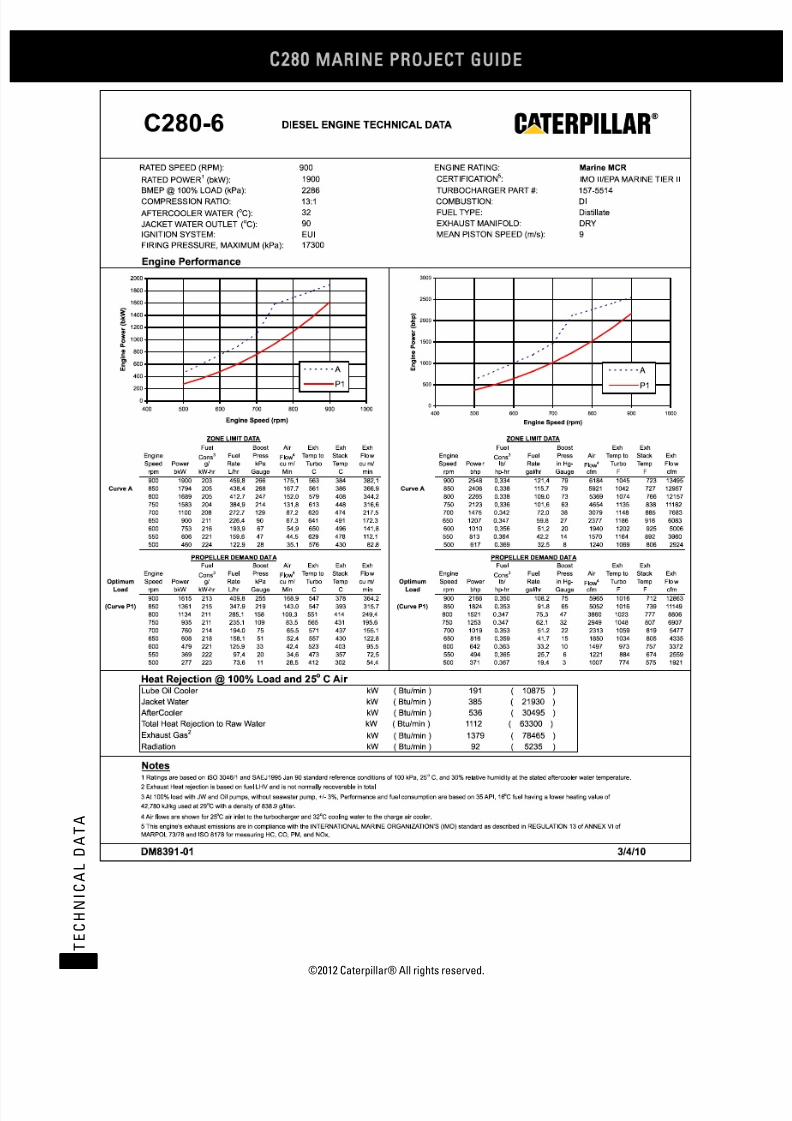
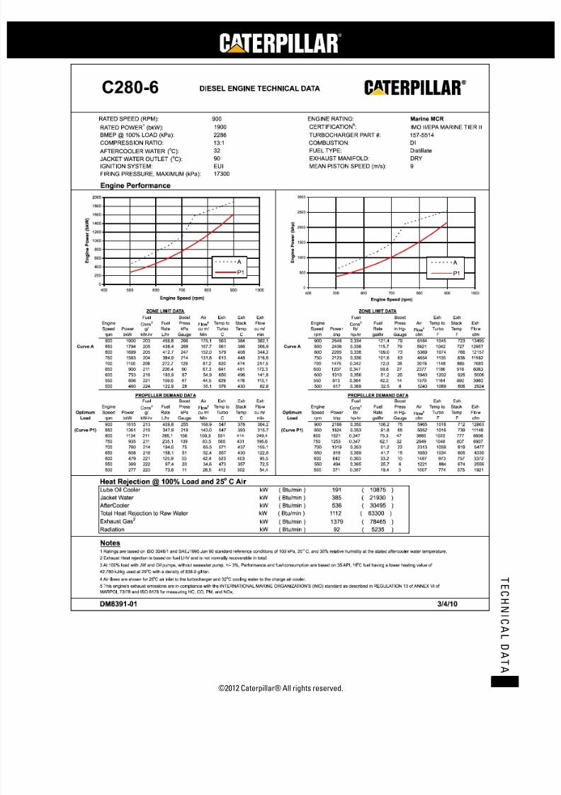
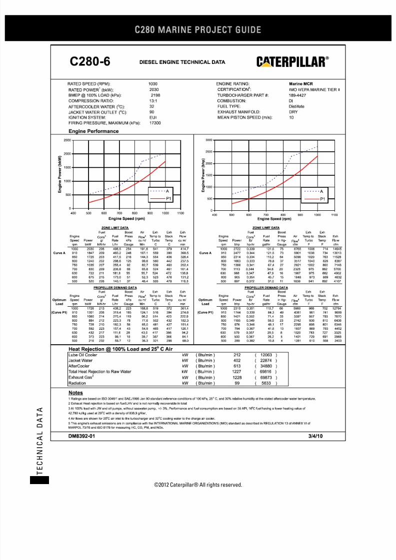
C280-6 DIESEL ENGINE TECHNICAL DATA
RATED SPEED (RPM): 900 ENGINE RATING: Marine CSR
RATED POWER (bkW):1 1730 CERTIFICATION :
5IMO II/EPA MARINE TIER II
BMEP @ 100% LOAD (kPa): 2082 TURBOCHARGER PART #: 157-5514COMPRESSION RATIO: 13:1 COMBUSTION: DI
AFTERCOOLER WATER (oC): 32 FUEL TYPE: Distillate
JACKET WATER OUTLET (oC): 90 EXHAUST MANIFOLD: DRY
IGNITION SYSTEM: EUI MEAN PISTON SPEED (m/s): 9
FIRING PRESSURE, MAXIMUM (kPa):
Engine Performance
ZONE LIMIT DATA ZONE LIMIT DATA
Fuel Boost Air Exh Exh Exh Fuel Boost Exh Exh
Engine Cons Fuel Press3Flow
4 Temp to Stack Flow Engine Cons Fuel Press3 Air Temp to Stack Exh
Speed Power g/ Rate kPa cu m/ Turbo Temp cu m/ Speed Power lb/ Rate in Hg- Flow4 Turbo Temp Flow
rpm bkW kW-hr L/hr Gauge Min C C min rpm bhp hp-hr gal/hr Gauge cfm F F cfm
900 1730 210 432.3 255 171.3 555 379 370.5 900 2320 0.345 114.1 75 6049 1031 714 13084
Curve A 850 1634 209 407.1 264 164.7 559 389 361.6 Curve A 850 2191 0.344 107.5 78 5815 1039 733 12771
800 1538 208 380.5 245 148.6 576 413 338.1 800 2062 0.342 100.5 73 5248 1069 775 11942
750 1442 206 354.3 209 127.3 605 447 305.1 750 1934 0.339 93.5 62 4495 1122 837 10775
700 987 209 245.9 111 79.7 609 464 196.3 700 1324 0.344 64.9 33 2815 1128 868 6932
650 841 212 212.9 82 64.3 631 480 162.0 650 1128 0.350 56.2 24 2270 1168 896 5721
600 704 217 181.9 60 52.6 633 482 133.0 600 944 0.357 48.0 18 1857 1172 899 4698
550 567 221 149.4 42 42.7 608 462 105.2 550 760 0.364 39.4 12 1508 1127 863 3716
500 430 223 114.4 25 33.9 553 411 77.6 500 577 0.367 30.2 7 1196 1028 772 2741
PROPELLER DEMAND DAT A PROPELLER DEMAND DATA
Fuel Boost Air Exh Exh Exh Fuel Boost Exh Exh
EngineCons
Fuel Press3
Flow
4 Temp to Stack Flow EngineCons
Fuel Press3 Air Temp to Stack Exh
Optimum Speed Power g/ Rate kPa cu m/ Turbo Temp cu m/ Optimum Speed Power lb/ Rate in Hg- Flow4 Turbo Temp Flow
Load rpm bkW kW-hr L/hr Gauge Min C C min Load rpm bhp hp-hr gal/hr Gauge cfm F F cfm
900 1557 215 399.0 253 166.8 545 378 359.8 900 2088 0.354 105.4 75 5891 1012 713 12705
(Curve P1) 850 1312 215 335.4 207 137.5 543 393 303.7 (Curve P1) 850 1759 0.353 88.6 61 4857 1010 740 10724
800 1094 211 275.3 148 105.2 547 413 239.8 800 1466 0.348 72.7 44 3717 1017 776 8468
750 901 212 227.5 103 81.0 560 428 189.0 750 1208 0.349 60.1 31 2860 1040 802 6674
700 733 215 187.8 71 63.9 563 433 150.4 700 982 0.354 49.6 21 2258 1046 811 5311
650 587 219 152.9 48 51.3 547 423 119.2 650 787 0.360 40.4 14 1813 1017 794 4210
600 461 221 121.6 31 41.7 512 395 92.7 600 619 0.364 32.1 9 1471 954 742 3274
550 355 222 94.0 18 34.1 462 348 70.4 550 477 0.365 24.8 5 1204 864 658 2487
500 267 223 71.1 10 28.2 402 294 53.1 500 358 0.368 18.8 3 997 756 561 1874
Heat Rejection @ 100% Load and 25o C Air
Lube Oil Cooler kW ( Btu/min ) 182 ( 10356 )
Jacket Water kW ( Btu/min ) 387 ( 22020 )
AfterCooler kW ( Btu/min ) 518 ( 29474 )
Total Heat Rejection to Raw Water kW ( Btu/min ) 1087 ( 61850 )
Exhaust Gas kW ( Btu/min ) 1321 ( 75165 )2
Radiation kW ( Btu/min ) 86 ( 4893 )
Notes1 Ratings are based on ISO 3046/1 and SAEJ1995 Jan 90 standard reference conditions of 100 kPa, 25 C, and 30% relative humidity at the stated aftercooler water temperature.
o
2 Exhaust Heat rejection is based on fuel LHV and is not normally recoverable in total
4 Air flows are shown for 25 C air inlet to the turbocharger and 32 C cooling water to the charge air cooler.o o
DM8389-01 3/4/10
3 At 100% load with JW and Oil pumps, without seawater pump, +/- 3%. Performance and fuel consumpt ion are based on 35 API, 16 C fuel having a lower heating value ofo
42,780 kJ/kg used at 29 C with a density of 838.9 g/liter.o
5 This engine's exhaust emissions are in compliance with the INTERNATIONAL MARINE ORGANIZATION'S (IMO) standard as described in REGULATION 13 of ANNEX VI of
MARPOL 73/78 and ISO 8178 for measuring HC, CO, PM, and NOx.
16200
0
200
400
600
800
1000
1200
1400
1600
1800
2000
400 500 600 700 800 900 1000
Engine Speed (rpm)
E n g i n e P o w e r ( b k W )
A
P1
0
500
1000
1500
2000
2500
400 500 600 700 800 900 1000
Engine Speed (rpm)
E n g i n e P o w e r ( b h p )
A
P1

7/23/2019 1.- c280 Epa Tier 2 - Imo II Marine Project Guide
http://slidepdf.com/reader/full/1-c280-epa-tier-2-imo-ii-marine-project-guide 21/222
©2012 Caterpillar® All rights reserved. 13
T E C H N I C A L D A T A

7/23/2019 1.- c280 Epa Tier 2 - Imo II Marine Project Guide
http://slidepdf.com/reader/full/1-c280-epa-tier-2-imo-ii-marine-project-guide 22/222
C28
MARINE PROJECT GUIDE
©2012 Caterpillar® All rights reserved.14
T E C H N I C A L D A T A
C280-6 MCR (Sheet 1 of 2)
bkW (bhp) (2548) 2030 (2722)
mm (in) (11.0) 280 (11.0)
mm (in) (11.8) 300 (11.8)
liters (in3) (1127) 18.5 (1127)
bar (psi) (2509) 173 (2509)
bar (psi) (331) 22.0 (319)
m/s (ft/s) (29.5) 10.0 (32.8)
mm H2O (in H2O) (5/15) 125/380 (5/15)
kPa (in H2O) (14.9) 3.7 (14.9)o
C (o
F) (142) 61 (142)oC (
oF) (208) 98 (208)
kPa (psi) (39) 254 (37)oC (
oF) (113) 45 (113)
m3/min (ft
3/min) (6,184) 192 (6,766)
kPa (in H2O) (16.1) 4.0 (16.1)
g/bkW-hr (lb/bhp-hr) (0.0153) 8.67 (0.0143)
g/bkW-hr (lb/bhp-hr) (0.0143) 7.96 (0.0131)
g/bkW-hr (lb/bhp-hr) (0.0010) 1.04 (0.0017)
g/bkW-hr (lb/bhp-hr) (0.0010) 0.71 (0.0012)
g/bkW-hr (lb/bhp-hr) (0.0003) 0.16 (0.0003)
oC (
oF) (122) 50 (122)
oC (
oF) (576) 298 (568)
oC (
oF) (723) 379 (714)
oC (oF) (1022) 550 (1022)oC (
oF) (1045) 541 (1006)
oC (
oF) (1166) 630 (1166)
m3/min (ft
3/min) (13,494) 415 (14,645)
cm H2O (in H2O) (10) 25.4 (10)
kW (Btu/min) (10,862) 212 (12,056)
kW (Btu/min) (21,895) 402 (22,861)
kW (Btu/min) (30,482) 613 (34,861)
kW (Btu/min) (78,422) 1228 (69,835)
kW (Btu/min) (5,232) 99 (5,630)
kW (Btu/min) (626) 12.5 (711)
kW (Btu/min) (24,084) 442 (25,147)
kW (Btu/min) (45,040) 898 (51,071)
kW (Btu/min) (69,124) 1,340 (76,219)
oC (oF) (151) 66 (151)oC (
oF) (162) 72 (162)
kPa (psi) (119) 820 (119)
kPa (psi) (79 - 158) 546 - 1090 (79 - 158)
kPa (psi) (38) 260 (38)
kPa (psi) (20) 140 (20)
kPa (psi) (11) 75 (11)
kPa (psi) (-2.9) -20 (-2.9)
kPa (psi) (51) 350 (51)
lpm (gpm) (10.0) 41.5 (11.0)
lpm (gpm) (8.0) 33.2 (8.8)
l/hr (gal/hr) (121.5) 498 (131.7)
g/bkW-hr (lb/bhp-hr) (0.334) 206.0 (0.339)
g/bkW-hr (lb/bhp-hr) (0.327) 202.1 (0.332)
g/bkW-hr (lb/bhp-hr) (0.321) 197.0 (0.324)BSFC (Without water pumps + 5%/- 0%)ISO 3046/1@ 100%
195.2
BSFC (With Pumps +/- 3%) SAE Std @ 100% Load Nominal5 203.0
BSFC (With Pumps + 5%/- 0%) ISO 3046/1@ 100% Load5 199.1
Flow Rate, Return 30.3
Fuel Consumption (With pumps +/- 3%) @ 100% Load5 460
Return Line Backpressure, Maximum 350
Flow Rate, Supply 38.0
Fuel Filter Differential Pressure, Alarm 75
Pump Suction Restriction, Maximum -20
Fuel Pressure, Alarm > 650 rpm 260
Fuel Pressure, Alarm < 650 rpm 140
Fuel Manifold Pressure Nominal @ 100% Load 820
Fuel Manifold Pressure Range @ 100% Load 546 - 1090
Fuel System
Fuel Temperature, Alarm 66
Fuel Temperature, Stop 72
Separate Circuit System (OC & AC) @ 32° C Inlet Temp (with 792
Combined Circuit System (JW, OC & AC) @ 32° C Inlet (with 1,216
Fuel Heat Rejection 11.0
Separate Circuit System (JW) @ 90° C Inlet Temp (with 424
Exhaust Gas4 1379
Radiation 92
Jacket Water 385
Aftercooler 536
Exhaust System Backpressure, Maximum3 25.4
Heat Balance @ 100% load and 25° C Air6
Lube Oil Cooler 191
Exhaust Temp to Turbo Alarm @ 100% Load 630
Exhaust Gas Flow @ 100% Load, Stack Temp & 101.3 kPa 382
Exhaust Stack Temp Alarm @ 100% Load 550Exhaust Temp to Turbo @ 100% Load 563
Minimum Exhaust Stack Temp (for SCR System design) 302
Exhaust Stack Temp @ 100% Load 384
Particulates 0.18
Exhaust Gas System
Exhaust Cyl Port Deviation Alarm (From Average) @ 100% Load 50
CO 0.63
THC (molecular weight of 13.018) 0.62
Emission Data (NOT TO EXCEED DATA)
NOx as NO2 + THC (molecular weight of 13.018) 9.30
NOx as NO2 8.68
Air Flow Rate @ 100% Load (25° C, 101.3 kPa) 175
Aftercooler Core Pressure Diff. @ 100% Load (Clean or New 4.0
Intake Manifold Pressure @ 100% Load 266
Ambient Air Temp. @ Air Cleaner, Maximum 45
Inlet Manifold Air Temp. Alarm 61Inlet Manifold Air Temp. Shutdown 98
Combustion Air System6
Air Filter Restriction, New/Maximum 125/380
Air Filter Restriction, Alarm 3.7
Firing Order – CCW (Standard Rotation) 1-5-3-6-2-4
Firing Order – CW (Reverse Rotation) 1-4-2-6-3-5
Time Before Overall (Main) hrs 36,000 - 44,000 36,000 - 44,000
Crash Reversal Speed, Minimum rpm 300 300
Idle Speed rpm 350 350
BMEP @ 100% Load 22.8
Mean Piston Speed 9.0
Compression Ratio 13:1 13:1
Firing Pressure, Maximum 173
Stroke 300
Displacement/Cylinder 18.5
Engine Output (IMO Certified) 1900
Cylinder Bore 280
General Data Performance DM# DM8391-01 DM8392-01
(See appropriate DM Performance sheet for additional specific data) Units 900 rpm 1000 rpm
Fuel: MDO/ #2/ ULSD
Engine Speed Ratings
Technical Data Engine: C280-6
EPA Tier 2 / IMO II Propulsion Engine Rating: MCR
7/23/2019 1.- c280 Epa Tier 2 - Imo II Marine Project Guide
http://slidepdf.com/reader/full/1-c280-epa-tier-2-imo-ii-marine-project-guide 23/222
©2012 Caterpillar® All rights reserved. 15
T E C H N I C A L D A T A
C280-6 MCR (Sheet 2 of 2)
kPa (psi) (55) 380 (55)
kPa (psi) (46) 320 (46)kPa (psi) (17) 120 (17)
kPa (psi) (38) 260 (38)
kPa (psi) (15) 105 (15)oC (
oF) (185) 85 (185)
oC (
oF) (198) 92 (198)
oC (
oF) (208) 98 (208)
kPa (psi) (15) 104 (15)
kPa (psi) (10) 70 (10)
kPa (psi) (24) 165 (24)
mm (in) (2) 50 (2)
liters (gal) (184) 697 (184)
lpm (gpm) (152) 577 (152)
lpm (gpm) (20) 76 (20)
lpm (gpm) (6) 23 (6)
l/hr (gal/hr) (0.39) 1.6 (0.41)
g/bkW-hr (lb/bhp-hr) (0.0012) 0.7 (0.0012)
oC (
oF) (181) 83 (181)
oC (
oF) (194) 90 (194)
oC (
oF) (203) 95 (203)
oC (
oF) (210) 99 (210)
oC (
oF) (217) 103 (217)
oC (
oF) (228) 109 (228)
kPa (psi) (4.4) 30 (4.4)
kPa (psi) (10) 70 (10)
kPa (psi) (34.8) 295 (42.8)
kPa (psi) (11.2) 99 (14.4)
lpm (gpm) (347) 1,460 (386)
oC (
oF) (90) 32 (90)
oC (
oF) (100) 38 (100)
oC (
oF) (102) 39 (102)
oC (
oF) (108) 42 (108)
kPa (psi) (-0.73) -5.0 (-0.73)
kPa (psi) (10) 70 (10)
kPa (psi) (34.8) 295 (42.8)
kPa (psi) (12.2) 104 (15.1)
kPa (psi) (10.3) 91 (13.2)
lpm (gpm) (325) 1365 (361)
bar (psi) (75) 5.2 (75)
bar (psi) (60) 4.1 (60)
bar (psi) (120) 8.3 (120)
bar (psi) (200) 13.8 (200)
bar (psi) (40) 2.8 (40)
bar (psi) (90) 6.2 (90)
Engine Power +/- 3%
Heat Rejection JW (Block) +/- 10%
Heat Rejection SCAC +/- 5%
Heat Rejection Radiant +/- 50%
Charge Air Pressure +/- 10%
Exhaust Flow +/- 5%
25° C (77° F)30° C (86° F) 40°C (104°F) 5°C (113°F 50°C (122°F)
1.00 1.03 1.13 1.18 1.23
1.00 1.00 0.97 0.95 0.94
8 Normal variation in cylinder to cylinder exhaust port temperatures from the average of exhaust port temperatures for the engine.
9 Shallow oil pan is available for light weight option and dry sump option available where required.
10 For full by-pass flow pressure drop multiply by 130%
4 Exhaust heat rejection is based on fuel LHV to 25° C and is not normally recoverable in total
5 At 100% loads with pumps +/- 3% except where specified differently. Performance and fuel consumption are based on 35 API, 16° C fuel having a lower heating of 42,780 kJ/kg
used at 29° C with a density of 838.9 g/liter. Does not include sea water pump pa6 Air Flows are shown for 25° C air inlet to the turbocharger and 32° C cooling water to the charge air cooler. Adjust aftercooler heat load for higher ambients using the Aftercooler
Heat Rejection Factors.7 This engine's exhaust emissions are in compliance with the International Marine Organization's (IMO) standard as described in Regulation 13 of ANNEX VI of MARPOL, 73/79 and
ISO 8178 for measuring HC, CO, PM, NOx.
Notes1 Continuous prelube system requires lines group for continuous prelube (Contact factory if prelube not factory supplied)
2 Ratings are based on ISO 3046/1 and SAEJ1995 Jan 1990 standard reference conditions of 100 kPa, 25° C, and 30% relative humidity at the stated aftercooler water temperature
3 Contact Factory for applications needing additional limits
Correction Factor (Multiply by AC heat load) 1.08
Power Derate Factors 0.98
Inlet Air Flow +/- 5%
Correction Factors (For Both Ratings) (Need to include in system heat load calculation if not @ 25° C ambient air temp)
Air to Turbo Temp. (Ambient Temp) 35°C (95° F)
Exhaust Stack Temperature +/- 8%
Fuel Rate +/- 5%
BSFC ISO 3046/1 + 5% / - 0%
Heat Rejection Oil Cooler (OC) +/- 20%
Air Pressure, Maximum Dynamic Pressure (HD Starter) 6.2
Tolerances
Specific Fuel Consumption +/- 3%
Air Pressure, Maximum Static Pressure (Standard or HD Starter) 13.8
Air Pressure, minimum (Engine Only, HD Starter) 2.8
Air Pressure, minimum (Engine Only, Std Starter) 4.1
Air Pressure, Maximum Dynamic Pressure (Standard Starter) 8.3
Pump Capacity (AC/OC Separate or JW, AC/OC Combined 1230
Starting Air System
Low Air Pressure, alarm 5.2
External Restriction Pressure Drop AC/OC Circuit (Full Flow)10 84
External Restriction JW, AC/OC Combined Circuit (Full Flow)10 71
AC/OC Water Pump Outlet Pressure, Alarm 70
Pump Rise (delta P) @ 32oC (90
oF) 240
Inlet Temp, Shutdown 42
Pump Inlet Pressure, Minimum -5.0
Inlet Temp, Maximum without derate3 38
Inlet Temp, Alarm 39
Pump Capacity (JW Circuit Only for Separate Circuit) 1,315
Cooling Water system – AC/OC Cooling
Inlet Temp, Nominal @ 27oC Sea Water Temp 32
Pump Rise (delta P) @ 85oC (185
oF) 240
External Restriction Pressure Drop (Full Flow)10 77
Pump Inlet Pressure, Minimum 30
Jacket Water Outlet Pressure, Alarm 70
Jacket Water Outlet Temperature, Alarm 103
Jacket Water Outlet Temperature, Shutdown 109
Inlet Temperature, Maximum 95
Outlet Temp before Regulator, Maximum 99
Cooling Water System – Block CoolingInlet Temperature, Minimum 83
Inlet Temperature, Nominal 90
Oil Consumption @ 100% load NOTE: May be higher at lower 1.5
BSOC @ 100% Load, Typical NOTE: Will be higher at lower 0.7
Prelube Pump Capacity, Intermittent 76
Prelube Pump Capacity, Continuous1 23
Sump Capacity (Marine Pan)9 697
Lube Oil Flow 577
Lube Oil Filter Differential Pressure, Shutdown 165
Lube Oil Sump Level, Alarm (Below Full Level) 50
Lube Oil Filter Differential Pressure, Maximum 104
Lube Oil Filter Differential Pressure, Alarm 70
Lube Oil Temperature, Alarm 92
Lube Oil Temperature, Shutdown 98
Lube Oil Pressure, Shutdown (0-650 rpm) 105
Lube Oil Temperature, Nominal 85
Lube Oil Pressure, Alarm (0-650 rpm) 120
Lube Oil Pressure, Shutdown (650-1000 rpm) 260
Lube Oil Pressure, Nominal 380
Lube Oil Pressure, Alarm (650-1000 rpm) 320
Lubricating Oil System Performance DM# DM8391-01 DM8392-01
(See appropriate DM Performance sheet for additional specific data) Units 900 rpm 1000 rpm
Fuel: MDO/ #2/ ULSD
Engine Speed Ratings
Technical Data Engine: C280-6
EPA Tier 2 / IMO II Propu lsion Engine Rating: MCR
7/23/2019 1.- c280 Epa Tier 2 - Imo II Marine Project Guide
http://slidepdf.com/reader/full/1-c280-epa-tier-2-imo-ii-marine-project-guide 24/222
C28
MARINE PROJECT GUIDE
©2012 Caterpillar® All rights reserved.16
T E C H N I C A L D A T A
7/23/2019 1.- c280 Epa Tier 2 - Imo II Marine Project Guide
http://slidepdf.com/reader/full/1-c280-epa-tier-2-imo-ii-marine-project-guide 25/222
©2012 Caterpillar® All rights reserved. 17
T E C H N I C A L D A T A
7/23/2019 1.- c280 Epa Tier 2 - Imo II Marine Project Guide
http://slidepdf.com/reader/full/1-c280-epa-tier-2-imo-ii-marine-project-guide 26/222
C28
MARINE PROJECT GUIDE
©2012 Caterpillar® All rights reserved.18
T E C H N I C A L D A T A

7/23/2019 1.- c280 Epa Tier 2 - Imo II Marine Project Guide
http://slidepdf.com/reader/full/1-c280-epa-tier-2-imo-ii-marine-project-guide 27/222
©2012 Caterpillar® All rights reserved. 19
T E C H N I C A L D A T A

7/23/2019 1.- c280 Epa Tier 2 - Imo II Marine Project Guide
http://slidepdf.com/reader/full/1-c280-epa-tier-2-imo-ii-marine-project-guide 28/222
C28
MARINE PROJECT GUIDE
©2012 Caterpillar® All rights reserved.20
T E C H N I C A L D A T A
C280-8 CSR (Sheet 1 of 2)
bkW (bhp) (3084) 2460 (3299)
mm (in) (11.0) 280 (11.0)
mm (in) (11.8) 300 (11.8)
liters (in3) (1127) 18.5 (1127)
bar (psi) (2350) 162 (2350)
bar (psi) (301) 20.0 (290)
m/s (ft/s) (29.5) 10.0 (32.8)
mm H2O (in H2O) (5/15) 125/380 (5/15)
kPa (in H2O) (14.9) 3.7 (14.9)o
C (o
F) (142) 61 (142)oC (
oF) (208) 98 (208)
kPa (psi) (38) 268 (39)oC (
oF) (113) 45 (113)
m3/min (ft
3/min) (8,889) 274 (9,680)
kPa (in H2O) (16.1) 4.0 (16.1)
g/bkW-hr (lb/bhp-hr) (0.0164) 10.33 (0.0170)
g/bkW-hr (lb/bhp-hr) (0.0152) 9.26 (0.0152)
g/bkW-hr (lb/bhp-hr) (0.0008) 0.64 (0.0011)
g/bkW-hr (lb/bhp-hr) (0.0012) 1.07 (0.0018)
g/bkW-hr (lb/bhp-hr) (0.0003) 0.18 (0.0003)
oC (
oF) (122) 50 (122)
oC (
oF) (651) 320 (608)
oC (
oF) (687) 375 (707)
oC (oF) (1022) 550 (1022)oC (
oF) (1009) 543 (1009)
oC (
oF) (1166) 630 (1166)
m3/min (ft
3/min) (18,731) 587 (20,744)
cm H2O (in H2O) (10) 25.4 (10)
kW (Btu/min) (13,762) 271 (15,411)
kW (Btu/min) (27,525) 499 (28,378)
kW (Btu/min) (39,581) 626 (35,600)
kW (Btu/min) (102,592) 2056 (116,923)
kW (Btu/min) (6,483) 125 (7,109)
kW (Btu/min) (830) 16.7 (950)
kW (Btu/min) (30,277) 549 (31,215)
kW (Btu/min) (58,075) 983 (55,874)
kW (Btu/min) (88,352) 1,531 (87,089)
oC (oF) (151) 66 (151)oC (
oF) (162) 72 (162)
kPa (psi) (119) 820 (119)
kPa (psi) (79 - 158) 546 - 1090 (79 - 158)
kPa (psi) (38) 260 (38)
kPa (psi) (20) 140 (20)
kPa (psi) (11) 75 (11)
kPa (psi) (-2.9) -20 (-2.9)
kPa (psi) (51) 350 (51)
lpm (gpm) (10.0) 41.5 (11.0)
lpm (gpm) (7.5) 31.1 (8.2)
l/hr (gal/hr) (149.9) 625 (165.0)
g/bkW-hr (lb/bhp-hr) (0.340) 213.0 (0.350)
g/bkW-hr (lb/bhp-hr) (0.334) 208.9 (0.344)
g/bkW-hr (lb/bhp-hr) (0.328) 204.6 (0.336)
Fuel Heat Rejection 14.6
Separate Circuit System (JW) @ 90° C Inlet Temp (with 532
Exhaust Gas Flow @ 100% Load, Stack Temp & 101.3 kPa 530
Exhaust System Backpressure, Maximum3 25.4
Radiation 114
550Exhaust Temp to Turbo @ 100% Load 543
Exhaust Temp to Turbo Alarm @ 100% Load 630
Exhaust Stack Temp Alarm @ 100% Load
Ambient Air Temp. @ Air Cleaner, Maximum 45
Combustion Air System6
Air Filter Restriction, New/Maximum 125/380
Air Filter Restriction, Alarm 3.7
98
Fuel: MDO/ #2/ ULSD
Crash Reversal Speed, Minimum rpm
Intake Manifold Pressure @ 100% Load 265
Exhaust Gas4 1804
Jacket Water 484
Aftercooler
36,000 - 44,000
Firing Order – CCW (Standard Rotation) 1-6-2-5-8-3-7-4
Firing Order – CW (Reverse Rotation) 1-4-7-3-8-5-2-6
61Inlet Manifold Air Temp. Shutdown
300 300
Engine Speed Ratings
Technical Data Engine: C280-8
EPA Tier 2 / IMO II Propulsion Engine Rating: CSR
(See appropriate DM Performance sheet for additional specific data) Units 900 rpm 1000 rpm
Engine Output (IMO Certified) 2300
Cylinder Bore 280
General Data Performance DM# DM8397-02 DM8398-02
Stroke 300
Displacement/Cylinder 18.5
Compression Ratio 13:1 13:1
Firing Pressure, Maximum 162
BMEP @ 100% Load 20.8
Mean Piston Speed 9.0
Idle Speed rpm 350 350
Air Flow Rate @ 100% Load (25° C, 101.3 kPa) 252
Time Before Overall (Main) hrs 36,000 - 44,000
Inlet Manifold Air Temp. Alarm
Aftercooler Core Pressure Diff. @ 100% Load (Clean or New 4.0
Emission Data (NOT TO EXCEED DATA)
NOx as NO2 + THC (molecular weight of 13.018) 10.00
NOx as NO2 9.27
CO 0.47
THC (molecular weight of 13.018)
Exhaust Cyl Port Deviation Alarm (From Average) @ 100% Load 50
0.73
Particulates 0.20
Exhaust Gas System
Minimum Exhaust Stack Temp (for SCR System design) 344
Exhaust Stack Temp @ 100% Load 364
Separate Circuit System (OC & AC) @ 32° C Inlet Temp (with 1,021
696
Heat Balance @ 100% load and 25° C Air6
Lube Oil Cooler 242
Combined Circuit System (JW, OC & AC) @ 32° C Inlet (with 1,554
Fuel System
Fuel Temperature, Alarm 66
Fuel Temperature, Stop 72
Fuel Manifold Pressure Nominal @ 100% Load 820
Fuel Manifold Pressure Range @ 100% Load 546 - 1090
Fuel Pressure, Alarm > 650 rpm 260
Pump Suction Restriction, Maximum -20
Fuel Pressure, Alarm < 650 rpm 140
Fuel Filter Differential Pressure, Alarm 75
Return Line Backpressure, Maximum 350
Fuel Consumption (With pumps +/- 3%) @ 100% Load5 568
Flow Rate, Supply 38.0
Flow Rate, Return 28.5
BSFC (With Pumps +/- 3%) SAE Std @ 100% Load Nominal5 207.0
BSFC (With Pumps + 5%/- 0%) ISO 3046/1@ 100% Load5 203.1
BSFC (Without water pumps + 5%/- 0%)ISO 3046/1@ 100%
199.8

7/23/2019 1.- c280 Epa Tier 2 - Imo II Marine Project Guide
http://slidepdf.com/reader/full/1-c280-epa-tier-2-imo-ii-marine-project-guide 29/222
©2012 Caterpillar® All rights reserved. 21
T E C H N I C A L D A T A
C280-8 CSR (Sheet 2 of 2)
kPa (psi) (55) 380 (55)
kPa (psi) (46) 320 (46)kPa (psi) (17) 120 (17)
kPa (psi) (38) 260 (38)
kPa (psi) (15) 105 (15)oC (
oF) (185) 85 (185)
oC (
oF) (198) 92 (198)
oC (
oF) (208) 98 (208)
kPa (psi) (15) 104 (15)
kPa (psi) (10) 70 (10)
kPa (psi) (24) 165 (24)
mm (in) (2) 50 (2)
liters (gal) (201) 760 (201)
lpm (gpm) (192) 728 (192)
lpm (gpm) (20) 76 (20)
lpm (gpm) (6) 23 (6)
l/hr (gal/hr) (0.47) 1.9 (0.50)
g/bkW-hr (lb/bhp-hr) (0.0012) 0.7 (0.0012)
oC (
oF) (181) 83 (181)
oC (
oF) (194) 90 (194)
oC (
oF) (203) 95 (203)
oC (
oF) (210) 99 (210)
oC (
oF) (217) 103 (217)
oC (
oF) (228) 109 (228)
kPa (psi) (4.4) 30 (4.4)
kPa (psi) (10) 70 (10)
kPa (psi) (34.8) 295 (42.8)
kPa (psi) (11.2) 99 (14.4)
lpm (gpm) (347) 1,460 (386)
oC (
oF) (90) 32 (90)
oC (
oF) (100) 38 (100)
oC (
oF) (102) 39 (102)
oC (
oF) (108) 42 (108)
kPa (psi) (-0.73) -5.0 (-0.73)
kPa (psi) (10) 70 (10)
kPa (psi) (34.8) 295 (42.8)
kPa (psi) (12.2) 104 (15.1)
kPa (psi) (10.3) 91 (13.2)
lpm (gpm) (325) 1365 (361)
bar (psi) (75) 5.2 (75)
bar (psi) (60) 4.1 (60)
bar (psi) (120) 8.3 (120)
bar (psi) (200) 13.8 (200)
bar (psi) (40) 2.8 (40)
bar (psi) (90) 6.2 (90)
Engine Power +/- 3%
Heat Rejection JW (Block) +/- 10%
Heat Rejection SCAC +/- 5%
Heat Rejection Radiant +/- 50%
Charge Air Pressure +/- 10%
Exhaust Flow +/- 5%
25° C (77° F)30° C (86° F) 40°C (104°F) 5°C (113°F)50°C (122°F)
1.00 1.03 1.13 1.18 1.23
1.00 1.00 0.97 0.95 0.94
10 For full by-pass flow pressure drop multiply by 130%
6 Air Flows are shown for 25° C air inlet to the turbocharger and 32° C cooling water to the charge air cooler. Adjust aftercooler heat load for higher ambients using the Aftercooler
Heat Rejection Factors.7 This engine's exhaust emissions are in compliance with the International Marine Organization's (IMO) standard as described in Regulation 13 of ANNEX VI of MARPOL, 73/79 and
ISO 8178 for measuring HC, CO, PM, NOx.8 Normal variation in cylinder to cylinder exhaust port temperatures from the average of exhaust port temperatures for the engine.
9 Shallow oil pan is available for light weight option and dry sump option available where required.
2 Ratings are based on ISO 3046/1 and SAEJ1995 Jan 1990 standard reference conditions of 100 kPa, 25° C, and 30% relative humidity at the stated aftercooler water temperature
3 Contact Factory for applications needing additional limits
4 Exhaust heat rejection is based on fuel LHV to 25° C and is not normally recoverable in total5 At 100% loads with pumps +/- 3% except where specified differently. Performance and fuel consumption are based on 35 API, 16° C fuel having a lower heating of 42,780 kJ/kg
used at 29° C with a density of 838.9 g/liter. Does not include sea water pump pa
Power Derate Factors 0.98
Notes1 Continuous prelube system requires lines group for continuous prelube (Contact factory if prelube not factory supplied)
Correction Factors (For Both Ratings) (Need to include in system heat load calculation if not @ 25° C ambient air temp)
Air to Turbo Temp. (Ambient Temp) 35°C (95° F)
Correction Factor (Multiply by AC heat load) 1.08
Fuel Rate +/- 5%
Inlet Air Flow +/- 5%
Heat Rejection Oil Cooler (OC) +/- 20%
Exhaust Stack Temperature +/- 8%
Tolerances
Specific Fuel Consumption +/- 3%
BSFC ISO 3046/1 + 5% / - 0%
Air Pressure, minimum (Engine Only, HD Starter) 2.8
Air Pressure, Maximum Dynamic Pressure (HD Starter) 6.2
Air Pressure, Maximum Dynamic Pressure (Standard Starter) 8.3
Air Pressure, Maximum Static Pressure (Standard or HD Starter) 13.8
Starting Air System
Low Air Pressure, alarm 5.2
Air Pressure, minimum (Engine Only, Std Starter) 4.1
External Restriction JW, AC/OC Combined Circuit (Full Flow)10 71
Pump Capacity (AC/OC Separate or JW, AC/OC Combined 1230
Pump Rise (delta P) @ 32oC (90
oF) 240
External Restriction Pressure Drop AC/OC Circuit (Full Flow)10 84
Pump Inlet Pressure, Minimum -5.0
AC/OC Water Pump Outlet Pressure, Alarm 70
760
Lube Oil Flow 728
Prelube Pump Capacity, Intermittent 76
Sump Capacity (Marine Pan)9
1000 rpm
Lubricating Oil System Performance DM# DM8397-02 DM8398-02
(See appropriate DM Performance sheet for additional specific data) Units 900 rpm
MDO/ #2/ ULSD
Engine Speed Ratings
Fuel:
Engine:Technical Data C280-8
Rating:EPA Tier 2 / IMO II Propuls ion Engine CSR
Lube Oil Pressure, Nominal 380
Lube Oil Pressure, Alarm (650-1000 rpm) 320Lube Oil Pressure, Alarm (0-650 rpm) 120
Lube Oil Pressure, Shutdown (650-1000 rpm) 260
Lube Oil Pressure, Shutdown (0-650 rpm) 105
Lube Oil Temperature, Shutdown 98
Lube Oil Temperature, Nominal 85
Lube Oil Temperature, Alarm 92
Lube Oil Filter Differential Pressure, Maximum 104
Lube Oil Filter Differential Pressure, Alarm 70
Lube Oil Filter Differential Pressure, Shutdown 165
Lube Oil Sump Level, Alarm (Below Full Level) 50
Prelube Pump Capacity, Continuous1 23
Oil Consumption @ 100% load NOTE: May be higher at lower 1.8
BSOC @ 100% Load, Typical NOTE: Will be higher at lower 0.7
Cooling Water System – Block CoolingInlet Temperature, Minimum 83
Inlet Temperature, Nominal 90
Inlet Temperature, Maximum 95
Outlet Temp before Regulator, Maximum 99
Jacket Water Outlet Temperature, Alarm 103
Jacket Water Outlet Temperature, Shutdown 109
Pump Inlet Pressure, Minimum 30
Jacket Water Outlet Pressure, Alarm 70
Pump Rise (delta P) @ 85oC (185
oF) 240
External Restriction Pressure Drop (Full Flow)10 77
Pump Capacity (JW Circuit Only for Separate Circuit) 1,315
Inlet Temp, Alarm 39
Inlet Temp, Shutdown
Cooling Water syst em – AC/OC Cooling
Inlet Temp, Nominal @ 27oC Sea Water Temp 32
Inlet Temp, Maximum without derate3 38
42

7/23/2019 1.- c280 Epa Tier 2 - Imo II Marine Project Guide
http://slidepdf.com/reader/full/1-c280-epa-tier-2-imo-ii-marine-project-guide 30/222
C28
MARINE PROJECT GUIDE
©2012 Caterpillar® All rights reserved.22
T E C H N I C A L D A T A
C280-8 DIESEL ENGINE TECHNICAL DATA
RATED SPEED (RPM): 900 ENGINE RATING: Marine CSR
RATED POWER (bkW):1 2300 CERTIFICATION :
5IMO II/EPA MARINE TIER II
BMEP @ 100% LOAD (kPa): 2076 TURBOCHARGER PART #: 284-8280COMPRESSION RATIO: 13:1 COMBUSTION: DI
AFTERCOOLER WATER (oC): 32 FUEL TYPE: Distillate
JACKET WATER OUTLET (oC): 90 EXHAUST MANIFOLD: DRY
IGNITION SYSTEM: EUI MEAN PISTON SPEED (m/s): 9
FIRING PRESSURE, MAXIMUM (kPa):
Engine Performance
ZONE LIMIT DATA ZONE LIMIT DATA
Fuel Boost Air Exh Exh Exh Fuel Boost Exh Exh
Engine Cons Fuel Press3Flow
4 Temp to Stack Flow Engine Cons Fuel Press3 Air Temp to Stack Exh
Speed Power g/ Rate kPa cu m/ Turbo Temp cu m/ Speed Power lb/ Rate in Hg- Flow4 Turbo Temp Flow
rpm bkW kW-hr L/hr Gauge Min C C min rpm bhp hp-hr gal/hr Gauge cfm F F cfm
900 2300 207 568.2 265 251.7 543 364 530.4 900 3084 0.341 150.0 78 8889 1009 687 18732
Curve A 850 2172 209 540.3 260 240.9 543 367 510.3 Curve A 850 2913 0.344 142.7 77 8508 1009 693 18020
800 2044 209 508.5 250 226.1 543 372 482.1 800 2742 0.344 134.3 74 7983 1010 701 17026
750 1917 196 446.9 209 192.3 528 373 411.1 750 2570 0.322 118.0 62 6790 982 703 14517
700 1266 203 306.7 124 132.9 517 399 295.5 700 1698 0.335 81.0 37 4693 962 750 10435
650 1029 202 248.1 77 97.8 530 431 228.3 650 1380 0.333 65.5 23 3453 985 807 8062
600 822 209 204.5 50 76.3 540 450 183.5 600 1103 0.343 54.0 15 2696 1005 843 6480
550 705 215 180.6 35 68.4 540 455 165.3 550 945 0.354 47.7 10 2414 1004 851 5838
500 587 218 152.7 24 51.6 538 458 125.8 500 787 0.359 40.3 7 1823 1000 856 4443
PROPELLER DEMAND DAT A PROPELLER DEMAND DATA
Fuel Boost Air Exh Exh Exh Fuel Boost Exh Exh
EngineCons
Fuel Press3
Flow
4 Temp to Stack Flow EngineCons
Fuel Press3 Air Temp to Stack Exh
Optimum Speed Power g/ Rate kPa cu m/ Turbo Temp cu m/ Optimum Speed Power lb/ Rate in Hg- Flow4 Turbo Temp Flow
Load rpm bkW kW-hr L/hr Gauge Min C C min Load rpm bhp hp-hr gal/hr Gauge cfm F F cfm
900 2070 214 527.3 253 242.4 529 358 505.3 900 2776 0.352 139.2 75 8559 984 676 17846
(Curve P1) 850 1744 210 437.2 213 210.3 500 348 430.8 (Curve P1) 850 2338 0.346 115.4 63 7428 932 658 15214
800 1454 206 356.7 167 172.7 485 352 356.2 800 1950 0.339 94.2 49 6100 904 666 12580
750 1198 204 291.6 119 135.2 483 373 288.7 750 1606 0.336 77.0 35 4776 902 704 10196
700 974 206 239.6 81 104.8 493 398 232.7 700 1306 0.340 63.3 24 3700 920 749 8219
650 780 211 196.0 51 80.9 500 416 184.7 650 1046 0.347 51.7 15 2857 931 781 6524
600 613 214 156.8 31 63.9 484 411 145.1 600 822 0.353 41.4 9 2258 903 773 5123
550 472 216 121.6 14 53.2 404 383 115.4 550 634 0.356 32.1 4 1878 759 721 4075
500 355 216 91.3 9 42.1 388 344 85.7 500 476 0.355 24.1 3 1485 730 651 3026
Heat Rejection @ 100% Load and 25o C Air
Lube Oil Cooler kW ( Btu/min ) 242 ( 13770 )
Jacket Water kW ( Btu/min ) 484 ( 27540 )
AfterCooler kW ( Btu/min ) 696 ( 39602 )
Total Heat Rejection to Raw Water kW ( Btu/min ) 1422 ( 80912 )
Exhaust Gas kW ( Btu/min ) 1804 ( 102648 )2
Radiation kW ( Btu/min ) 114 ( 6487 )
Notes1 Ratings are based on ISO 3046/1 and SAEJ1995 Jan 90 standard reference conditions of 100 kPa, 25 C, and 30% relative humidity at the stated aftercooler water temperature.
o
2 Exhaust Heat rejection is based on fuel LHV and is not normally recoverable in total
4 Air flows are shown for 25 C air inlet to the turbocharger and 32 C cooling water to the charge air cooler.o o
DM8397-02 3/15/10
3 At 100% load with JW and Oil pumps, without seawater pump, +/- 3%. Performance and fuel consumption are based on 35 API, 16C fuel having a lower heating value ofo
42,780 kJ/kg used at 29 C with a density of 838.9 g/liter.o
5 This engine's exhaust emissions are in compliance with the INTERNATIONAL MARINE ORGANIZATION'S (IMO) standard as described in REGULATION 13 of ANNEX VI of
MARPOL 73/78 and ISO 8178 for measuring HC, CO, PM, and NOx.
16200
0
500
1000
1500
2000
2500
400 500 600 700 800 900 1000
Engine Speed (rpm)
E n g i n e P o w e r ( b k W )
A
P1
0
500
1000
1500
2000
2500
3000
3500
400 500 600 700 800 900 1000
Engine Speed (rpm)
E n g i n e P o w e r ( b h p )
A
P1

7/23/2019 1.- c280 Epa Tier 2 - Imo II Marine Project Guide
http://slidepdf.com/reader/full/1-c280-epa-tier-2-imo-ii-marine-project-guide 31/222
©2012 Caterpillar® All rights reserved. 23
T E C H N I C A L D A T A
C280-8 DIESEL ENGINE TECHNICAL DATA
RATED SPEED (RPM): 1000 ENGINE RATING: Marine CSR
RATED POWER (bkW):1 2460 CERTIFICATION :
5IMO II/EPA MARINE TIER II
BMEP @ 100% LOAD (kPa): 1998 TURBOCHARGER PART #: 284-8276COMPRESSION RATIO: 13:1 COMBUSTION: DI
AFTERCOOLER WATER (oC): 32 FUEL TYPE: Distillate
JACKET WATER INLET (oC): 90 EXHAUST MANIFOLD: DRY
IGNITION SYSTEM: EUI MEAN PISTON SPEED (m/s): 10
FIRING PRESSURE, MAXIMUM (kPa):
Engine Performance
ZONE LIMIT DATA ZONE LIMIT DATA
Fuel Boost Air Exh Exh Exh Fuel Boost Exh Exh
Engine Cons Fuel Press3Flow
4 Temp to Stack Flow Engine Cons Fuel Press3 Air Temp to Stack Exh
Speed Power g/ Rate kPa cu m/ Turbo Temp cu m/ Speed Power lb/ Rate in Hg- Flow4 Turbo Temp Flow
rpm bkW kW-hr L/hr Gauge Min C C min rpm bhp hp-hr gal/hr Gauge cfm F F cfm
1000 2460 213 624.4 268 274.1 543 375 587.4 1000 3299 0.351 164.9 79 9680 1010 707 20743
Curve A 950 2337 212 589.8 258 263.3 541 368 557.9 Curve A 950 3134 0.349 155.7 76 9297 1006 694 19702
910 2239 211 562.6 243 247.8 544 374 530.6 910 3002 0.347 148.5 72 8751 1011 706 18739
850 2091 210 523.3 213 216.7 562 405 487.0 850 2804 0.346 138.2 63 7652 1043 762 17200
800 1474 212 372.7 115 139.6 584 466 343.0 800 1976 0.349 98.4 34 4929 1082 872 12112
750 1212 217 313.7 77 105.2 615 509 274.5 750 1625 0.357 82.8 23 3717 1138 948 9693
700 950 223 252.1 47 78.5 628 536 212.2 700 1274 0.367 66.6 14 2772 1163 996 7494
630 760 227 205.8 29 59.5 634 545 163.2 630 1019 0.374 54.3 9 2101 1172 1013 5762
600 741 229 202.1 26 55.4 654 561 155.3 600 994 0.377 53.4 8 1956 1210 1042 5484
500 532 236 149.8 12 38.9 616 523 104.3 500 714 0.389 39.6 4 1375 1141 973 3685
PROPELLER DEMAND DATA PROPELLER DEMAND DATA
Fuel Boost Air Exh Exh Exh Fuel Boost Exh Exh
Engine Cons Fuel Press3Flow
4 Temp to Stack Flow Engine Cons Fuel Press3 Air Temp to Stack Exh
Optimum Speed Power g/ Rate kPa cu m/ Turbo Temp cu m/ Optimum Speed Power lb/ Rate in Hg- Flow4 Turbo Temp Flow
Load rpm bkW kW-hr L/hr Gauge Min C C min Load rpm bhp hp-hr gal/hr Gauge cfm F F cfm
1000 2214 215 567.6 247 268.3 523 361 562.0 1000 2969 0.354 149.9 73 9474 973 683 19847
(Curve P1) 950 1898 216 489.1 204 230.7 524 378 495.6 (Curve P1) 950 2546 0.356 129.1 60 8148 974 712 17502
910 1668 214 425.5 160 192.2 529 402 428.8 910 2237 0.352 112.3 47 6787 983 756 15143
850 1360 214 347.2 104 140.8 550 446 335.6 850 1823 0.353 91.7 31 4974 1022 835 11853
800 1134 218 294.7 71 109.1 571 479 272.9 800 1520 0.359 77.8 21 3854 1060 895 9638
750 934 222 247.0 48 85.5 585 501 220.5 750 1253 0.365 65.2 14 3019 1085 935 7789
700 759 225 203.6 31 68.0 579 501 175.5 700 1018 0.370 53.8 9 2400 1074 934 6198
630 554 229 150.8 16 50.6 528 458 123.4 630 742 0.376 39.8 5 1788 982 857 4360
600 478 230 131.3 11 44.9 496 429 105.1 600 641 0.379 34.7 3 1586 924 805 3711
500 277 237 78.2 3 31.7 370 320 62.3 500 371 0.390 20.6 1 1119 698 607 2199
Heat Rejection @ 100% Load and 2 5o C Air
Lube Oil Cooler kW ( Btu/min ) 271 ( 15420 )
Jacket Water kW ( Btu/min ) 499 ( 28393 )
AfterCooler kW ( Btu/min ) 626 ( 35619 )
Total Heat Rejection to Raw Water kW ( Btu/min ) 1396 ( 79432 )
Exhaust Gas kW ( Btu/min ) 2056 ( 116986 )2
Radiation kW ( Btu/min ) 125 ( 7113 )
Notes1 Ratings are based on ISO 3046/1 and SAEJ1995 Jan 90 standard reference condit ions of 100 kPa, 25 C, and 30% relative humidity at the stated aftercooler water temperature.
o
2 Exhaust Heat rejection is based on fuel LHV and is not normally recoverable in total
4 Air flows are shown for 25 C air inlet to the turbocharger and 32 C cooling water to the charge air cooler.o o
DM8398-02 3/4/10
3 At 100% load with JW and Oil pumps, without seawater pump, +/- 3%. Performance and fuel consumpt ion are based on 35 API, 16 C fuel having a lower heating value ofo
42,780 kJ/kg used at 29 C with a density of 838.9 g/liter.o
5 This engine's exhaust emissions are in compliance with the INTERNATIONAL MARINE ORGANIZATION'S (IMO) standard as described in REGULATION 13 of ANNEX VI of
MARPOL 73/78 and ISO 8178 for measuring HC, CO, PM, and NOx.
16200
0
500
1000
1500
2000
2500
3000
400 500 600 700 800 900 1000 1100
Engine Speed (rpm)
E n g i n e P o w e r ( b k W )
A
P1
0
500
1000
1500
2000
2500
3000
3500
400 500 600 700 800 900 1000 1100
Engine Speed (rpm)
E n g i n e P o w e r ( b h p )
A
P1

7/23/2019 1.- c280 Epa Tier 2 - Imo II Marine Project Guide
http://slidepdf.com/reader/full/1-c280-epa-tier-2-imo-ii-marine-project-guide 32/222
C28
MARINE PROJECT GUIDE
©2012 Caterpillar® All rights reserved.24
T E C H N I C A L D A T A
C280-8 MCR (Sheet 1 of 2)
bkW (bhp) (3393) 2710 (3634)
mm (in) (11.0) 280 (11.0)
mm (in) (11.8) 300 (11.8)
liters (in3) (1127) 18.5 (1127)
bar (psi) (2509) 173 (2509)
bar (psi) (331) 22.0 (319)
m/s (ft/s) (29.5) 10.0 (32.8)
mm H2O (in H2O) (5/15) 125/380 (5/15)
kPa (in H2O) (14.9) 3.7 (14.9)o
C (o
F) (142) 61 (142)oC (
oF) (208) 98 (208)
kPa (psi) (41) 289 (42)oC (
oF) (113) 45 (113)
m3/min (ft
3/min) (9,295) 288 (10,153)
kPa (in H2O) (16.1) 4.0 (16.1)
g/bkW-hr (lb/bhp-hr) (0.0158) 9.87 (0.0162)
g/bkW-hr (lb/bhp-hr) (0.0146) 8.88 (0.0146)
g/bkW-hr (lb/bhp-hr) (0.0011) 0.73 (0.0012)
g/bkW-hr (lb/bhp-hr) (0.0012) 0.99 (0.0016)
g/bkW-hr (lb/bhp-hr) (0.0003) 0.17 (0.0003)
oC (
oF) (122) 50 (122)
oC (
oF) (640) 329 (624)
oC (
oF) (698) 386 (727)
oC (oF) (1022) 550 (1022)oC (
oF) (1029) 563 (1045)
oC (
oF) (1166) 630 (1166)
m3/min (ft
3/min) (19,776) 628 (22,167)
cm H2O (in H2O) (10) 25.4 (10)
kW (Btu/min) (14,502) 284 (16,151)
kW (Btu/min) (29,174) 537 (30,539)
kW (Btu/min) (40,718) 883 (50,215)
kW (Btu/min) (110,724) 2272 (129,206)
kW (Btu/min) (6,995) 137 (7,791)
kW (Btu/min) (830) 16.7 (950)
kW (Btu/min) (32,091) 591 (33,593)
kW (Btu/min) (60,156) 1,268 (72,107)
kW (Btu/min) (92,247) 1,859 (105,700)
oC (oF) (151) 66 (151)oC (
oF) (162) 72 (162)
kPa (psi) (119) 820 (119)
kPa (psi) (79 - 158) 546 - 1090 (79 - 158)
kPa (psi) (38) 260 (38)
kPa (psi) (20) 140 (20)
kPa (psi) (11) 75 (11)
kPa (psi) (-2.9) -20 (-2.9)
kPa (psi) (51) 350 (51)
lpm (gpm) (10.0) 41.5 (11.0)
lpm (gpm) (7.3) 30.0 (7.9)
l/hr (gal/hr) (162.5) 688 (181.8)
g/bkW-hr (lb/bhp-hr) (0.335) 213.0 (0.350)
g/bkW-hr (lb/bhp-hr) (0.329) 208.9 (0.344)
g/bkW-hr (lb/bhp-hr) (0.324) 205.0 (0.337)
716
Separate Circuit System (OC & AC) @ 32° C Inlet Temp (with 1,058
Combined Circuit System (JW, OC & AC) @ 32° C Inlet (with 1,622
564Separate Circuit System (JW) @ 90° C Inlet Temp (with
Radiation 123
Fuel Heat Rejection 14.6
NOx as NO2 + THC (molecular weight of 13.018) 9.58
Aftercooler Core Pressure Diff. @ 100% Load (Clean or New
550
50
NOx as NO2 8.87
CO 0.66
THC (molecular weight of 13.018)
Intake Manifold Pressure @ 100% Load 284
4.0
Emission Data (NOT TO EXCEED DATA)
Crash Reversal Speed, Minimum rpm 300 300
61Inlet Manifold Air Temp. Shutdown 98
1-6-2-5-8-3-7-4
Air Filter Restriction, Alarm 3.7
Inlet Manifold Air Temp. Alarm
Displacement/Cylinder 18.5
BMEP @ 100% Load 22.8
MDO/ #2/ ULSD
Stroke 300
General Data Performance DM# DM8399-01 DM8400-02
(See appropriate DM Performance sheet for additional specific data) Units 1000 rpm
Return Line Backpressure, Maximum 350
Flow Rate, Supply 38.0
546 - 1090
Fuel Pressure, Alarm > 650 rpm 260
Fuel Pressure, Alarm < 650 rpm
Pump Suction Restriction, Maximum -20
Exhaust Stack Temp Alarm @ 100% Load
Exhaust Gas4 1947
Lube Oil Cooler 255
Jacket Water 513
Exhaust Temp to Turbo @ 100% Load 554
Aftercooler
Exhaust Gas System
Exhaust System Backpressure, Maximum3 25.4
Heat Balance @ 100% load and 25° C Air6
Minimum Exhaust Stack Temp (for SCR System design) 338
Exhaust Stack Temp @ 100% Load 370
Exhaust Gas Flow @ 100% Load, Stack Temp & 101.3 kPa 560
350
Compression Ratio 13:1 13:1
Firing Pressure, Maximum 173
Mean Piston Speed 9.0
Idle Speed rpm
Technical Data Engine: C280-8
EPA Tier 2 / IMO II Propulsion Engine Rating: MCR
Engine Output (IMO Certified) 2530
Cylinder Bore 280
900 rpm
Fuel:
Engine Speed Ratings
hrs 36,000 - 44,000
350
36,000 - 44,000
Air Filter Restriction, New/Maximum 125/380Combustion Air System
6
Time Before Overall (Main)
Firing Order – CW (Reverse Rotation) 1-4-7-3-8-5-2-6
Firing Order – CCW (Standard Rotation)
Exhaust Temp to Turbo Alarm @ 100% Load 630
Ambient Air Temp. @ Air Cleaner, Maximum 45
Air Flow Rate @ 100% Load (25° C, 101.3 kPa) 263
Exhaust Cyl Port Deviation Alarm (From Average) @ 100% Load
0.71
Particulates 0.19
Fuel System
Fuel Temperature, Alarm
140
Fuel Filter Differential Pressure, Alarm 75
66
Fuel Temperature, Stop 72
Fuel Manifold Pressure Nominal @ 100% Load 820
Fuel Consumption (With pumps +/- 3%) @ 100% Load5 615
BSFC (With Pumps +/- 3%) SAE Std @ 100% Load Nominal5 204.0
BSFC (With Pumps + 5%/- 0%) ISO 3046/1@ 100% Load5 200.1
Flow Rate, Return 27.7
Fuel Manifold Pressure Range @ 100% Load
BSFC (Without water pumps + 5%/- 0%)ISO 3046/1@ 100%
197.2
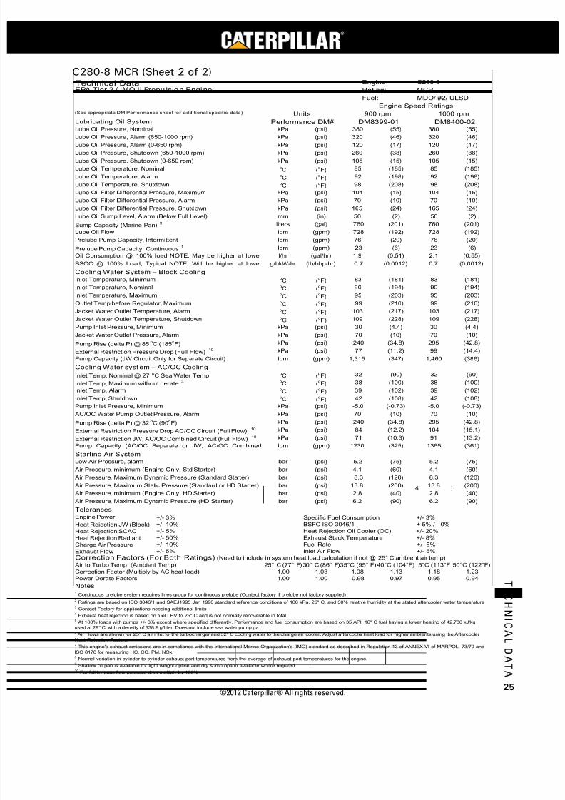
7/23/2019 1.- c280 Epa Tier 2 - Imo II Marine Project Guide
http://slidepdf.com/reader/full/1-c280-epa-tier-2-imo-ii-marine-project-guide 33/222
©2012 Caterpillar® All rights reserved. 25
T E C H N I C A L D A T A
C280-8 MCR (Sheet 2 of 2)
kPa (psi) (55) 380 (55)
kPa (psi) (46) 320 (46)kPa (psi) (17) 120 (17)
kPa (psi) (38) 260 (38)
kPa (psi) (15) 105 (15)oC (
oF) (185) 85 (185)
oC (
oF) (198) 92 (198)
oC (
oF) (208) 98 (208)
kPa (psi) (15) 104 (15)
kPa (psi) (10) 70 (10)
kPa (psi) (24) 165 (24)
mm (in) (2) 50 (2)
liters (gal) (201) 760 (201)
lpm (gpm) (192) 728 (192)
lpm (gpm) (20) 76 (20)
lpm (gpm) (6) 23 (6)
l/hr (gal/hr) (0.51) 2.1 (0.55)
g/bkW-hr (lb/bhp-hr) (0.0012) 0.7 (0.0012)
oC (
oF) (181) 83 (181)
oC (
oF) (194) 90 (194)
oC (
oF) (203) 95 (203)
oC (
oF) (210) 99 (210)
oC (
oF) (217) 103 (217)
oC (
oF) (228) 109 (228)
kPa (psi) (4.4) 30 (4.4)
kPa (psi) (10) 70 (10)
kPa (psi) (34.8) 295 (42.8)
kPa (psi) (11.2) 99 (14.4)
lpm (gpm) (347) 1,460 (386)
oC (
oF) (90) 32 (90)
oC (
oF) (100) 38 (100)
oC (
oF) (102) 39 (102)
oC (
oF) (108) 42 (108)
kPa (psi) (-0.73) -5.0 (-0.73)
kPa (psi) (10) 70 (10)
kPa (psi) (34.8) 295 (42.8)
kPa (psi) (12.2) 104 (15.1)
kPa (psi) (10.3) 91 (13.2)
lpm (gpm) (325) 1365 (361)
bar (psi) (75) 5.2 (75)
bar (psi) (60) 4.1 (60)
bar (psi) (120) 8.3 (120)
bar (psi) (200) 13.8 (200)
bar (psi) (40) 2.8 (40)
bar (psi) (90) 6.2 (90)
Engine Power +/- 3%
Heat Rejection JW (Block) +/- 10%
Heat Rejection SCAC +/- 5%
Heat Rejection Radiant +/- 50%
Charge Air Pressure +/- 10%
Exhaust Flow +/- 5%
25° C (77° F)30° C (86° F) 40°C (104°F) 5°C (113°F 50°C (122°F)
1.00 1.03 1.13 1.18 1.23
1.00 1.00 0.97 0.95 0.94
8 Normal variation in cylinder to cylinder exhaust port temperatures from the average of exhaust port temperatures for the engine.
9 Shallow oil pan is available for light weight option and dry sump option available where required.
10 For full by-pass flow pressure drop multiply by 130%
4 Exhaust heat rejection is based on fuel LHV to 25° C and is not normally recoverable in total
5 At 100% loads with pumps +/- 3% except where specified differently. Performance and fuel consumption are based on 35 API, 16° C fuel having a lower heating of 42,780 kJ/kg
used at 29° C with a density of 838.9 g/liter. Does not include sea water pump pa6 Air Flows are shown for 25° C air inlet to the turbocharger and 32° C cooling water to the charge air cooler. Adjust aftercooler heat load for higher ambients using the Aftercooler
Heat Rejection Factors.7 This engine's exhaust emissions are in compliance with the International Marine Organization's (IMO) standard as described in Regulation 13 of ANNEX VI of MARPOL, 73/79 and
ISO 8178 for measuring HC, CO, PM, NOx.
Notes1 Continuous prelube system requires lines group for continuous prelube (Contact factory if prelube not factory supplied)
2 Ratings are based on ISO 3046/1 and SAEJ1995 Jan 1990 standard reference conditions of 100 kPa, 25° C, and 30% relative humidity at the stated aftercooler water temperature
3 Contact Factory for applications needing additional limits
Correction Factor (Multiply by AC heat load) 1.08
Power Derate Factors 0.98
Correction Factors (For Both Ratings) (Need to include in system heat load calculation if not @ 25° C ambient air temp)
Air to Turbo Temp. (Ambient Temp) 35°C (95° F)
Exhaust Stack Temperature +/- 8%
Fuel Rate +/- 5%
70
Pump Rise (delta P) @ 85oC (185
oF) 240
Pump Inlet Pressure, Minimum
Inlet Air Flow +/- 5%
Prelube Pump Capacity, Intermittent 76
Prelube Pump Capacity, Continuous1 23
Lube Oil Flow
30
1000 rpm
Lubricating Oil System Performance DM# DM8399-01 DM8400-02
MDO/ #2/ ULSDFuel:
Engine:
Rating:
Jacket Water Outlet Temperature, Alarm 103
Oil Consumption @ 100% load NOTE: May be higher at lower 1.9
BSOC @ 100% Load, Typical NOTE: Will be higher at lower
Cooling Water System – Block CoolingInlet Temperature, Minimum 83
Inlet Temperature, Nominal 90
Inlet Temperature, Maximum 95
0.7
Lube Oil Sump Level, Alarm (Below Full Level) 50
Sump Capacity (Marine Pan)9 760
Lube Oil Filter Differential Pressure, Alarm 70
Lube Oil Filter Differential Pressure, Shutdown 165
728
Lube Oil Temperature, Shutdown 98
Lube Oil Filter Differential Pressure, Maximum 104
Lube Oil Temperature, Nominal 85
Lube Oil Temperature, Alarm 92
Lube Oil Pressure, Shutdown (650-1000 rpm) 260
Lube Oil Pressure, Shutdown (0-650 rpm) 105
Lube Oil Pressure, Alarm (650-1000 rpm) 320Lube Oil Pressure, Alarm (0-650 rpm) 120
Engine Speed Ratings
C280-8
EPA Tier 2 / IMO II Propu lsion Engine MCR
900 rpm
Lube Oil Pressure, Nominal 380
(See appropriate DM Performance sheet for additional specific data) Units
Technical Data
99
External Restriction Pressure Drop (Full Flow)10 77
Pump Capacity (JW Circuit Only for Separate Circuit) 1,315
Cooling Water syst em – AC/OC Cooling
Jacket Water Outlet Temperature, Shutdown 109
Outlet Temp before Regulator, Maximum
Jacket Water Outlet Pressure, Alarm
Inlet Temp, Nominal @ 27oC Sea Water Temp 32
Inlet Temp, Maximum without derate3 38
Inlet Temp, Alarm 39
Inlet Temp, Shutdown
Pump Rise (delta P) @ 32oC (90
oF) 240
42
Pump Inlet Pressure, Minimum -5.0
AC/OC Water Pump Outlet Pressure, Alarm 70
External Restriction Pressure Drop AC/OC Circuit (Full Flow)10 84
External Restriction JW, AC/OC Combined Circuit (Full Flow)10
Low Air Pressure, alarm 5.2
71
Pump Capacity (AC/OC Separate or JW, AC/OC Combined 1230
Starting Air System
Air Pressure, minimum (Engine Only, Std Starter) 4.1
Air Pressure, Maximum Dynamic Pressure (Standard Starter)
Air Pressure, Maximum Dynamic Pressure (HD Starter) 6.2
8.3
Air Pressure, Maximum Static Pressure (Standard or HD Starter) 13.8
Air Pressure, minimum (Engine Only, HD Starter) 2.8
Heat Rejection Oil Cooler (OC) +/- 20%
Tolerances
Specific Fuel Consumption +/- 3%
BSFC ISO 3046/1 + 5% / - 0%

7/23/2019 1.- c280 Epa Tier 2 - Imo II Marine Project Guide
http://slidepdf.com/reader/full/1-c280-epa-tier-2-imo-ii-marine-project-guide 34/222
C28
MARINE PROJECT GUIDE
©2012 Caterpillar® All rights reserved.26
T E C H N I C A L D A T A
C280-8 DIESEL ENGINE TECHNICAL DATA
RATED SPEED (RPM): 900 ENGINE RATING: Marine MCR
RATED POWER (bkW):1 2530 CERTIFICATION :
5IMO II/EPA MARINE TIER II
BMEP @ 100% LOAD (kPa): 2283 TURBOCHARGER PART #: 284-8280COMPRESSION RATIO: 13:1 COMBUSTION: DI
AFTERCOOLER WATER (oC): 32 FUEL TYPE: Distillate
JACKET WATER OUTLET (oC): 90 EXHAUST MANIFOLD: DRY
IGNITION SYSTEM: EUI MEAN PISTON SPEED (m/s): 9
FIRING PRESSURE, MAXIMUM (kPa):
Engine Performance
ZONE LIMIT DATA ZONE LIMIT DATA
Fuel Boost Air Exh Exh Exh Fuel Boost Exh Exh
Engine Cons Fuel Press3Flow
4 Temp to Stack Flow Engine Cons Fuel Press3 Air Temp to Stack Exh
Speed Power g/ Rate kPa cu m/ Turbo Temp cu m/ Speed Power lb/ Rate in Hg- Flow4 Turbo Temp Flow
rpm bkW kW-hr L/hr Gauge Min C C min rpm bhp hp-hr gal/hr Gauge cfm F F cfm
900 2530 204 616.3 284 263.2 554 370 560.0 900 3393 0.336 162.7 84 9296 1028 697 19778
Curve A 850 2389 203 577.3 273 248.6 550 369 528.3 Curve A 850 3204 0.334 152.4 81 8779 1022 696 18657
800 2249 202 540.9 262 233.9 546 370 497.7 800 3016 0.332 142.8 78 8261 1015 698 17576
750 2108 195 489.1 233 206.8 540 374 442.9 750 2827 0.320 129.1 69 7304 1004 705 15642
700 1417 199 336.7 144 145.1 519 392 319.1 700 1900 0.328 88.9 43 5124 967 737 11270
650 1204 198 284.1 99 110.4 541 429 257.0 650 1614 0.326 75.0 29 3898 1006 804 9077
600 986 203 238.7 66 85.2 564 462 208.4 600 1322 0.334 63.0 20 3009 1047 864 7361
550 818 214 208.6 43 70.9 584 472 176.0 550 1097 0.352 55.1 13 2503 1083 882 6217
500 650 218 168.9 29 53.9 572 484 136.2 500 871 0.359 44.6 9 1903 1062 903 4812
PROPELLER DEMAND DAT A PROPELLER DEMAND DATA
Fuel Boost Air Exh Exh Exh Fuel Boost Exh Exh
EngineCons
Fuel Press3
Flow
4 Temp to Stack Flow EngineCons
Fuel Press3 Air Temp to Stack Exh
Optimum Speed Power g/ Rate kPa cu m/ Turbo Temp cu m/ Optimum Speed Power lb/ Rate in Hg- Flow4 Turbo Temp Flow
Load rpm bkW kW-hr L/hr Gauge Min C C min Load rpm bhp hp-hr gal/hr Gauge cfm F F cfm
900 2151 211 541.7 258 246.3 531 357 512.7 900 2884 0.348 143.0 76 8697 988 674 18106
(Curve P1) 850 1812 211 455.8 224 217.2 508 350 446.5 (Curve P1) 850 2430 0.347 120.3 66 7670 946 662 15767
800 1511 206 370.6 175 178.9 486 350 367.6 800 2026 0.339 97.8 52 6317 907 661 12981
750 1245 204 302.4 127 140.3 486 372 298.8 750 1669 0.336 79.9 38 4955 908 701 10551
700 1012 206 248.1 86 108.1 495 400 240.5 700 1357 0.339 65.5 25 3817 924 751 8494
650 810 210 202.5 54 82.9 504 419 190.0 650 1087 0.345 53.5 16 2926 939 786 6711
600 637 214 162.3 34 65.9 489 415 150.3 600 855 0.352 42.9 10 2326 913 780 5309
550 491 222 129.9 11 48.9 458 388 107.5 550 658 0.366 34.3 3 1728 856 730 3796
500 369 228 100.2 9 42.5 386 338 86.1 500 495 0.375 26.5 3 1503 727 640 3039
Heat Rejection @ 100% Load and 25o C Air
Lube Oil Cooler kW ( Btu/min ) 255 ( 14483 )
Jacket Water kW ( Btu/min ) 513 ( 29187 )
AfterCooler kW ( Btu/min ) 716 ( 40747 )
Total Heat Rejection to Raw Water kW ( Btu/min ) 1484 ( 84418 )
Exhaust Gas kW ( Btu/min ) 1947 ( 110784 )2
Radiation kW ( Btu/min ) 123 ( 6999 )
Notes1 Ratings are based on ISO 3046/1 and SAEJ1995 Jan 90 standard reference conditions of 100 kPa, 25 C, and 30% relative humidity at the stated aftercooler water temperature.
o
2 Exhaust Heat rejection is based on fuel LHV and is not normally recoverable in total
4 Air flows are shown for 25 C air inlet to the turbocharger and 32 C cooling water to the charge air cooler.o o
DM8399-01 3/4/10
3 At 100% load with JW and Oil pumps, without seawater pump, +/- 3%. Performance and fuel consumpt ion are based on 35 API, 16 C fuel having a lower heating value ofo
42,780 kJ/kg used at 29 C with a density of 838.9 g/liter.o
5 This engine's exhaust emissions are in compliance with the INTERNATIONAL MARINE ORGANIZATION'S (IMO) standard as described in REGULATION 13 of ANNEX VI of
MARPOL 73/78 and ISO 8178 for measuring HC, CO, PM, and NOx.
17300
0
500
1000
1500
2000
2500
3000
400 500 600 700 800 900 1000
Engine Speed (rpm)
E n g i n e P o w e r ( b k W )
A
P1
0
500
1000
1500
2000
2500
3000
3500
4000
400 500 600 700 800 900 1000
Engine Speed (rpm)
E n g i n e P o w e r ( b h p )
A
P1
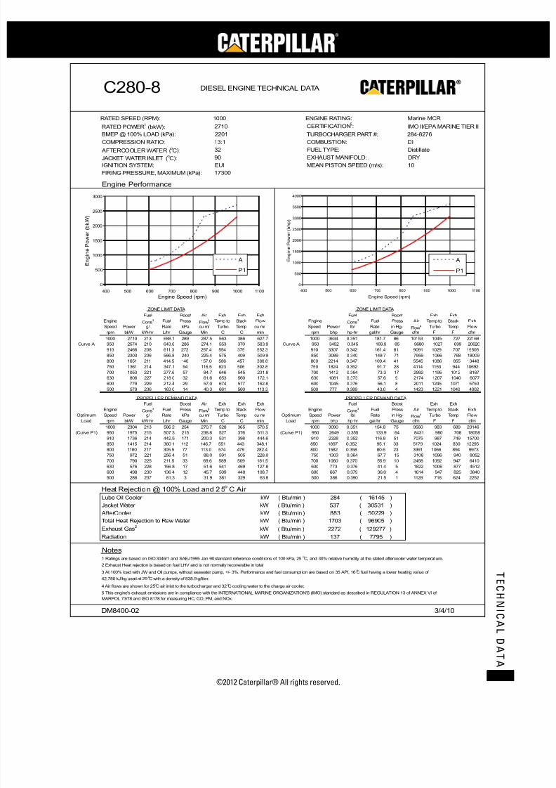
7/23/2019 1.- c280 Epa Tier 2 - Imo II Marine Project Guide
http://slidepdf.com/reader/full/1-c280-epa-tier-2-imo-ii-marine-project-guide 35/222
©2012 Caterpillar® All rights reserved. 27
T E C H N I C A L D A T A
C280-8 DIESEL ENGINE TECHNICAL DATA
RATED SPEED (RPM): 1000 ENGINE RATING: Marine MCR
RATED POWER (bkW):1 2710 CERTIFICATION :
5IMO II/EPA MARINE TIER II
BMEP @ 100% LOAD (kPa): 2201 TURBOCHARGER PART #: 284-8276COMPRESSION RATIO: 13:1 COMBUSTION: DI
AFTERCOOLER WATER (oC): 32 FUEL TYPE: Distillate
JACKET WATER INLET (oC): 90 EXHAUST MANIFOLD: DRY
IGNITION SYSTEM: EUI MEAN PISTON SPEED (m/s): 10
FIRING PRESSURE, MAXIMUM (kPa):
Engine Performance
ZONE LIMIT DATA ZONE LIMIT DATA
Fuel Boost Air Exh Exh Exh Fuel Boost Exh Exh
Engine Cons Fuel Press3Flow
4 Temp to Stack Flow Engine Cons Fuel Press3 Air Temp to Stack Exh
Speed Power g/ Rate kPa cu m/ Turbo Temp cu m/ Speed Power lb/ Rate in Hg- Flow4 Turbo Temp Flow
rpm bkW kW-hr L/hr Gauge Min C C min rpm bhp hp-hr gal/hr Gauge cfm F F cfm
1000 2710 213 688.1 289 287.5 563 386 627.7 1000 3634 0.351 181.7 86 10153 1045 727 22168
Curve A 950 2574 210 643.6 286 274.1 553 370 583.9 Curve A 950 3452 0.345 169.9 85 9680 1027 699 20620
910 2466 208 611.3 272 257.4 554 375 552.3 910 3307 0.342 161.4 81 9091 1029 707 19505
850 2303 206 566.8 240 225.4 575 409 509.9 850 3089 0.340 149.7 71 7959 1066 768 18009
800 1651 211 414.5 140 157.0 586 457 380.8 800 2214 0.347 109.4 41 5545 1086 855 13448
750 1361 214 347.1 94 116.5 623 506 302.8 750 1824 0.352 91.7 28 4114 1153 944 10692
700 1053 221 277.6 57 84.7 646 545 231.8 700 1412 0.364 73.3 17 2992 1195 1012 8187
630 806 227 218.0 32 61.6 653 560 172.1 630 1081 0.373 57.6 9 2174 1207 1040 6077
600 779 229 212.4 29 57.0 674 577 162.8 600 1045 0.376 56.1 8 2011 1245 1071 5750
500 579 236 163.0 14 40.3 661 560 113.3 500 777 0.389 43.0 4 1423 1221 1040 4002
PROPELLER DEMAND DATA PROPELLER DEMAND DATA
Fuel Boost Air Exh Exh Exh Fuel Boost Exh Exh
Engine Cons Fuel Press3Flow
4 Temp to Stack Flow Engine Cons Fuel Press3 Air Temp to Stack Exh
Optimum Speed Power g/ Rate kPa cu m/ Turbo Temp cu m/ Optimum Speed Power lb/ Rate in Hg- Flow4 Turbo Temp Flow
Load rpm bkW kW-hr L/hr Gauge Min C C min Load rpm bhp hp-hr gal/hr Gauge cfm F F cfm
1000 2304 213 586.2 254 270.7 528 365 570.5 1000 3090 0.351 154.8 75 9560 983 689 20146
(Curve P1) 950 1975 215 507.3 215 238.8 527 376 511.3 (Curve P1) 950 2649 0.355 133.9 64 8431 980 708 18058
910 1736 214 442.5 171 200.3 531 398 444.6 910 2328 0.352 116.8 51 7075 987 749 15700
850 1415 214 360.1 112 146.7 551 443 348.1 850 1897 0.352 95.1 33 5179 1024 830 12295
800 1180 217 305.5 77 113.0 574 479 282.4 800 1582 0.358 80.6 23 3991 1066 894 9973
750 972 221 256.4 51 88.0 591 505 228.0 750 1303 0.364 67.7 15 3108 1096 940 8052
700 790 225 211.5 33 69.6 589 509 181.5 700 1060 0.370 55.9 10 2458 1092 947 6410
630 576 228 156.8 17 51.6 541 469 127.8 630 773 0.376 41.4 5 1822 1006 877 4512
600 498 230 136.4 12 45.7 509 440 108.7 600 667 0.379 36.0 4 1614 947 825 3840
500 288 237 81.3 3 31.9 381 329 63.8 500 386 0.390 21.5 1 1128 718 624 2252
Heat Rejection @ 100% Load and 25o C Air
Lube Oil Cooler kW ( Btu/min ) 284 ( 16145 )
Jacket Water kW ( Btu/min ) 537 ( 30531 )
AfterCooler kW ( Btu/min ) 883 ( 50229 )
Total Heat Rejection to Raw Water kW ( Btu/min ) 1703 ( 96905 )
Exhaust Gas kW ( Btu/min ) 2272 ( 129277 )2
Radiation kW ( Btu/min ) 137 ( 7795 )
Notes1 Ratings are based on ISO 3046/1 and SAEJ1995 Jan 90 standard reference condit ions of 100 kPa, 25 C, and 30% relative humidity at the stated aftercooler water temperature.
o
2 Exhaust Heat rejection is based on fuel LHV and is not normally recoverable in total
4 Air flows are shown for 25 C air inlet to the turbocharger and 32 C cooling water to the charge air cooler.o o
DM8400-02 3/4/10
3 At 100% load with JW and Oil pumps, without seawater pump, +/- 3%. Performance and fuel consumpt ion are based on 35 API, 16 C fuel having a lower heating value ofo
42,780 kJ/kg used at 29 C with a density of 838.9 g/liter.o
5 This engine's exhaust emissions are in compliance with the INTERNATIONAL MARINE ORGANIZATION'S (IMO) standard as described in REGULATION 13 of ANNEX VI of
MARPOL 73/78 and ISO 8178 for measuring HC, CO, PM, and NOx.
17300
0
500
1000
1500
2000
2500
3000
400 500 600 700 800 900 1000 1100
Engine Speed (rpm)
E n g i n e P o w e r ( b k W )
A
P1
0
500
1000
1500
2000
2500
3000
3500
4000
400 500 600 700 800 900 1000 1100
Engine Speed (rpm)
E n g i n e P o w e r ( b h p )
A
P1

7/23/2019 1.- c280 Epa Tier 2 - Imo II Marine Project Guide
http://slidepdf.com/reader/full/1-c280-epa-tier-2-imo-ii-marine-project-guide 36/222
C28
MARINE PROJECT GUIDE
©2012 Caterpillar® All rights reserved.28
T E C H N I C A L D A T A
C280-12 CSR (Sheet 1 of 2)
bkW (bhp) (4640) 3700 (4962)
mm (in) (11.0) 280 (11.0)
mm (in) (11.8) 300 (11.8)
liters (in3) (1127) 18.5 (1127)
bar (psi) (2350) 162 (2350)
bar (psi) (302) 20.0 (291)
m/s (ft/s) (29.5) 10.0 (32.8)
mm H2O (in H2O) (5/15) 125/380 (5/15)
kPa (in H2O) (14.9) 3.7 (14.9)o
C (o
F) (142) 61 (142)oC (
oF) (208) 98 (208)
kPa (psi) (36) 224 (32)oC (
oF) (113) 45 (113)
m3/min (ft
3/min) (11,795) 341 (12,039)
kPa (in H2O) (16.1) 4.0 (16.1)
g/bkW-hr (lb/bhp-hr) (0.0168) 9.69 (0.0159)
g/bkW-hr (lb/bhp-hr) (0.0158) 8.89 (0.0146)
g/bkW-hr (lb/bhp-hr) (0.0008) 0.91 (0.0015)
g/bkW-hr (lb/bhp-hr) (0.0010) 0.80 (0.0013)
g/bkW-hr (lb/bhp-hr) (0.0003) 0.17 (0.0003)
oC (
oF) (122) 50 (122)
oC (
oF) (561) 293 (559)
oC (
oF) (712) 374 (705)
oC (oF) (1022) 550 (1022)oC (
oF) (1024) 523 (973)
oC (
oF) (1166) 630 (1166)
m3/min (ft
3/min) (25,480) 733 (25,875)
cm H2O (in H2O) (10) 25.4 (10)
kW (Btu/min) (20,700) 377 (21,440)
kW (Btu/min) (41,344) 758 (43,107)
kW (Btu/min) (54,708) 1188 (67,560)
kW (Btu/min) (145,642) 2768 (157,413)
kW (Btu/min) (9,611) 179 (10,180)
kW (Btu/min) (1,251) 25.0 (1,422)
kW (Btu/min) (45,478) 834 (47,417)
kW (Btu/min) (82,284) 1,700 (96,666)
kW (Btu/min) (127,762) 2,534 (144,083)
oC (oF) (151) 66 (151)oC (
oF) (162) 72 (162)
kPa (psi) (119) 820 (119)
kPa (psi) (79 - 158) 546 - 1090 (79 - 158)
kPa (psi) (38) 260 (38)
kPa (psi) (20) 140 (20)
kPa (psi) (11) 75 (11)
kPa (psi) (-2.9) -20 (-2.9)
kPa (psi) (51) 350 (51)
lpm (gpm) (19.0) 78.5 (20.7)
lpm (gpm) (15.3) 63.5 (16.8)
l/hr (gal/hr) (224.5) 900 (237.7)
g/bkW-hr (lb/bhp-hr) (0.339) 204.0 (0.335)
g/bkW-hr (lb/bhp-hr) (0.332) 200.1 (0.329)
g/bkW-hr (lb/bhp-hr) (0.329) 197.3 (0.324)BSFC (Without water pumps + 5%/- 0%)ISO 3046/1@ 100%
199.9
BSFC (With Pumps +/- 3%) SAE Std @ 100% Load Nominal5 206.0
BSFC (With Pumps + 5%/- 0%) ISO 3046/1@ 100% Load5 202.1
Flow Rate, Return 57.8
Fuel Consumption (With pumps +/- 3%) @ 100% Load5 850
Return Line Backpressure, Maximum 350
Flow Rate, Supply 72.0
Fuel Filter Differential Pressure, Alarm 75
Pump Suction Restriction, Maximum -20
Fuel Pressure, Alarm > 650 rpm 260
Fuel Pressure, Alarm < 650 rpm 140
Fuel Manifold Pressure Nominal @ 100% Load 820
Fuel Manifold Pressure Range @ 100% Load 546 - 1090
Fuel System
Fuel Temperature, Alarm 66
Fuel Temperature, Stop 72
Separate Circuit System (OC & AC) @ 32° C Inlet Temp (with 1,447
Combined Circuit System (JW, OC & AC) @ 32° C Inlet (with 2,247
Fuel Heat Rejection 22.0
Separate Circuit System (JW) @ 90° C Inlet Temp (with 800
Exhaust Gas4 2561
Radiation 169
Jacket Water 727
Aftercooler 962
Exhaust System Backpressure, Maximum3 25.4
Heat Balance @ 100% load and 25° C Air6
Lube Oil Cooler 364
Exhaust Temp to Turbo Alarm @ 100% Load 630
Exhaust Gas Flow @ 100% Load, Stack Temp & 101.3 kPa 722
Exhaust Stack Temp Alarm @ 100% Load 550Exhaust Temp to Turbo @ 100% Load 551
Minimum Exhaust Stack Temp (for SCR System design) 294
Exhaust Stack Temp @ 100% Load 378
Particulates 0.16
Exhaust Gas System
Exhaust Cyl Port Deviation Alarm (From Average) @ 100% Load 50
CO 0.51
THC (molecular weight of 13.018) 0.60
Emission Data (NOT TO EXCEED DATA)
NOx as NO2 + THC (molecular weight of 13.018) 10.20
NOx as NO2 9.60
Air Flow Rate @ 100% Load (25° C, 101.3 kPa) 334
Aftercooler Core Pressure Diff. @ 100% Load (Clean or New 4.0
Intake Manifold Pressure @ 100% Load 245
Ambient Air Temp. @ Air Cleaner, Maximum 45
Inlet Manifold Air Temp. Alarm 61Inlet Manifold Air Temp. Shutdown 98
Combustion Air System6
Air Filter Restriction, New/Maximum 125/380
Air Filter Restriction, Alarm 3.7
Firing Order – CCW (Standard Rotation) 1-12-9-4-5-8-11-2-3-10-7-6
Firing Order – CW (Reverse Rotation) 1-6-7-10-3-2-11-8-5-4-9-12
Time Before Overall (Main) hrs 36,000 - 44,000 36,000 - 44,000
Crash Reversal Speed, Minimum rpm 300 300
Idle Speed rpm 350 350
BMEP @ 100% Load 20.8
Mean Piston Speed 9.0
Compression Ratio 13:1 13:1
Firing Pressure, Maximum 162
Stroke 300
Displacement/Cylinder 18.5
Engine Output (IMO Certified) 3460
Cylinder Bore 280
General Data Performance DM# DM8405-01 DM8406-01
(See appropr iate DM Performance sheet fo r addition al specific data) Units 900 rpm 1000 rpm
Fuel: MDO/ #2/ ULSD
Engine Speed Ratings
Technical Data Engine: C280-12
EPA Tier 2 / IMO II Propulsion Engine Rating: CSR

7/23/2019 1.- c280 Epa Tier 2 - Imo II Marine Project Guide
http://slidepdf.com/reader/full/1-c280-epa-tier-2-imo-ii-marine-project-guide 37/222
©2012 Caterpillar® All rights reserved. 29
T E C H N I C A L D A T A
C280-12 CSR (Sheet 2 of 2)
kPa (psi) (55) 380 (55)
kPa (psi) (46) 320 (46)kPa (psi) (17) 120 (17)
kPa (psi) (38) 260 (38)
kPa (psi) (15) 105 (15)oC (
oF) (185) 85 (185)
oC (
oF) (198) 92 (198)
oC (
oF) (208) 98 (208)
kPa (psi) (15) 104 (15)
kPa (psi) (10) 70 (10)
kPa (psi) (24) 165 (24)
mm (in) (2) 50 (2)
liters (gal) (240) 910 (240)
lpm (gpm) (229) 868 (229)
lpm (gpm) (20) 76 (20)
lpm (gpm) (6) 23 (6)
l/hr (gal/hr) (0.70) 2.8 (0.75)
g/bkW-hr (lb/bhp-hr) (0.0012) 0.7 (0.0012)
oC (
oF) (181) 83 (181)
oC (
oF) (194) 90 (194)
oC (
oF) (203) 95 (203)
oC (
oF) (210) 99 (210)
oC (
oF) (217) 103 (217)
oC (
oF) (228) 109 (228)
kPa (psi) (4.4) 30 (4.4)
kPa (psi) (10) 70 (10)
kPa (psi) (34.8) 295 (42.8)
kPa (psi) (11.7) 103 (14.9)
lpm (gpm) (695) 2,920 (771)
oC (
oF) (90) 32 (90)
oC (
oF) (100) 38 (100)
oC (
oF) (102) 39 (102)
oC (
oF) (108) 42 (108)
kPa (psi) (-0.73) -5.0 (-0.73)
kPa (psi) (10) 70 (10)
kPa (psi) (35.5) 305 (44.2)
kPa (psi) (9.6) 85 (12.3)
kPa (psi) (9.6) 85 (12.3)
lpm (gpm) (412) 1730 (457)
bar (psi) (75) 5.2 (75)
bar (psi) (60) 4.1 (60)
bar (psi) (150) 10.4 (150)
bar (psi) (200) 13.8 (200)
bar (psi) (40) 2.8 (40)
bar (psi) (150) 10.4 (150)
Engine Power +/- 3%
Heat Rejection JW (Block) +/- 10%
Heat Rejection SCAC +/- 5%
Heat Rejection Radiant +/- 50%
Charge Air Pressure +/- 10%
Exhaust Flow +/- 5%
25° C (77° F)30° C (86° F) 40°C (104°F) 5°C (113°F 50°C (122°F)
1.00 1.03 1.13 1.18 1.23
1.00 1.00 0.97 0.95 0.94
8 Normal variation in cylinder to cylinder exhaust port temperatures from the average of exhaust port temperatures for the engine.
9 Shallow oil pan is available for light weight option and dry sump option available where required.
10 For full by-pass flow pressure drop multiply by 130%
4 Exhaust heat rejection is based on fuel LHV to 25° C and is not normally recoverable in total
5 At 100% loads with pumps +/- 3% except where specified differently. Performance and fuel consumption are based on 35 API, 16° C fuel having a lower heating of 42,780 kJ/kg
used at 29° C with a density of 838.9 g/liter. Does not include sea water pump pa6 Air Flows are shown for 25° C air inlet to the turbocharger and 32° C cooling water to the charge air cooler. Adjust aftercooler heat load for higher ambients using the Aftercooler
Heat Rejection Factors.7 This engine's exhaust emissions are in compliance with the International Marine Organization's (IMO) standard as described in Regulation 13 of ANNEX VI of MARPOL, 73/79 and
ISO 8178 for measuring HC, CO, PM, NOx.
Notes1 Continuous prelube system requires lines group for continuous prelube (Contact factory if prelube not factory supplied)
2 Ratings are based on ISO 3046/1 and SAEJ1995 Jan 1990 standard reference conditions of 100 kPa, 25° C, and 30% relative humidity at the stated aftercooler water temperature
3 Contact Factory for applications needing additional limits
Correction Factor (Multiply by AC heat load) 1.08
Power Derate Factors 0.98
Inlet Air Flow +/- 5%Correction Factors (For Both Ratings) (Need to include in system heat load calculation if not @ 25° C ambient air temp)
Air to Turbo Temp. (Ambient Temp) 35°C (95° F)
Exhaust Stack Temperature +/- 8%
Fuel Rate +/- 5%
BSFC ISO 3046/1 + 5% / - 0%
Heat Rejection Oil Cooler (OC) +/- 20%
Air Pressure, Maximum Dynamic Pressure (Dual Starter) 10.4
Tolerances
Specific Fuel Consumption +/- 3%
Air Pressure, Maximum Static Pressure (Standard or Dual 13.8
Air Pressure, minimum (Engine Only, Dual Starter) 2.8
Air Pressure, minimum (Engine Only, Std Starter) 4.1
Air Pressure, Maximum Dynamic Pressure (Standard Starter) 10.4
Pump Capacity (AC/OC Separate or JW, AC/OC Combined 1560
Starting Air System
Low Air Pressure, alarm 5.2
External Restriction Pressure Drop AC/OC Circuit (Full Flow)10 66
External Restriction JW, AC/OC Combined Circuit (Full Flow)10 66
AC/OC Water Pump Outlet Pressure, Alarm 70
Pump Rise (delta P) @ 32oC (90
oF) 245
Inlet Temp, Shutdown 42
Pump Inlet Pressure, Minimum -5.0
Inlet Temp, Maximum without derate3 38
Inlet Temp, Alarm 39
Pump Capacity (JW Circuit Only for Separate Circuit) 2,630
Cooling Water syst em – AC/OC Cooling
Inlet Temp, Nominal @ 27oC Sea Water Temp 32
Pump Rise (delta P) @ 85oC (185
oF) 240
External Restriction Pressure Drop (Full Flow)10 81
Pump Inlet Pressure, Minimum 30
Jacket Water Outlet Pressure, Alarm 70
Jacket Water Outlet Temperature, Alarm 103
Jacket Water Outlet Temperature, Shutdown 109
Inlet Temperature, Maximum 95
Outlet Temp before Regulator, Maximum 99
Cooling Water System – Block CoolingInlet Temperature, Minimum 83
Inlet Temperature, Nominal 90
Oil Consumption @ 100% load NOTE: May be higher at lower 2.7
BSOC @ 100% Load, Typical NOTE: Will be higher at lower 0.7
Prelube Pump Capacity, Intermittent 76
Prelube Pump Capacity, Continuous1 23
Sump Capacity (Marine Pan)9 910
Lube Oil Flow 868
Lube Oil Filter Differential Pressure, Shutdown 165
Lube Oil Sump Level, Alarm (Below Full Level) 50
Lube Oil Filter Differential Pressure, Maximum 104
Lube Oil Filter Differential Pressure, Alarm 70
Lube Oil Temperature, Alarm 92
Lube Oil Temperature, Shutdown 98
Lube Oil Pressure, Shutdown (0-650 rpm) 105
Lube Oil Temperature, Nominal 85
Lube Oil Pressure, Alarm (0-650 rpm) 120
Lube Oil Pressure, Shutdown (650-1000 rpm) 260
Lube Oil Pressure, Nominal 380
Lube Oil Pressure, Alarm (650-1000 rpm) 320
Lubricating Oil System Performance DM# DM8405-01 DM8406-01
(See appropriate DM Performance sheet for additio nal specific data) Units 900 rpm 1000 rpm
Fuel: MDO/ #2/ ULSD
Engine Speed Ratings
Technical Data Engine: C280-12
EPA Tier 2 / IMO II Propulsion Engine Rating: CSR
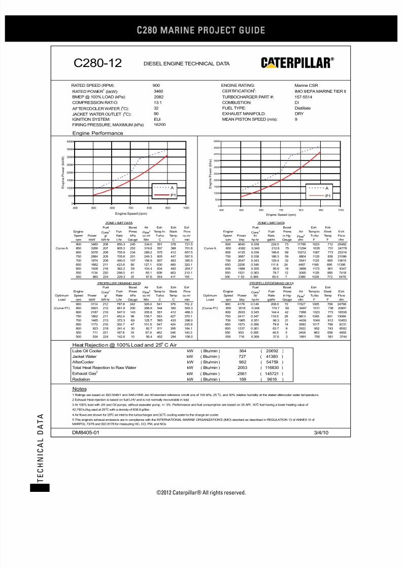
7/23/2019 1.- c280 Epa Tier 2 - Imo II Marine Project Guide
http://slidepdf.com/reader/full/1-c280-epa-tier-2-imo-ii-marine-project-guide 38/222
C28
MARINE PROJECT GUIDE
©2012 Caterpillar® All rights reserved.30
T E C H N I C A L D A T A
C280-12 DIESEL ENGINE TECHNICAL DATA
RATED SPEED (RPM): 900 ENGINE RATING: Marine CSR
RATED POWER (bkW):1 3460 CERTIFICATION :
5IMO II/EPA MARINE TIER II
BMEP @ 100% LOAD (kPa): 2082 TURBOCHARGER PART #: 157-5514COMPRESSION RATIO: 13:1 COMBUSTION: DI
AFTERCOOLER WATER (oC): 32 FUEL TYPE: Distillate
JACKET WATER OUTLET (oC): 90 EXHAUST MANIFOLD: DRY
IGNITION SYSTEM: EUI MEAN PISTON SPEED (m/s): 9
FIRING PRESSURE, MAXIMUM (kPa):
Engine Performance
ZONE LIMIT DATA ZONE LIMIT DATA
Fuel Boost Air Exh Exh Exh Fuel Boost Exh Exh
Engine Cons Fuel Press3Flow
4 Temp to Stack Flow Engine Cons Fuel Press3 Air Temp to Stack Exh
Speed Power g/ Rate kPa cu m/ Turbo Temp cu m/ Speed Power lb/ Rate in Hg- Flow4 Turbo Temp Flow
rpm bkW kW-hr L/hr Gauge Min C C min rpm bhp hp-hr gal/hr Gauge cfm F F cfm
900 3460 206 850.3 245 334.0 551 378 721.5 900 4640 0.339 224.5 73 11795 1023 712 25482
Curve A 850 3268 207 805.3 252 319.8 557 388 701.6 Curve A 850 4382 0.340 212.6 75 11294 1035 731 24778
800 3076 206 755.9 234 289.2 575 412 657.5 800 4125 0.339 199.6 69 10212 1067 773 23219
750 2884 205 705.8 201 249.3 605 447 597.5 750 3867 0.338 186.3 59 8804 1120 836 21099
700 1974 208 490.0 107 156.9 607 463 385.5 700 2647 0.343 129.4 32 5541 1125 865 13615
650 1682 211 423.8 80 127.1 630 480 320.1 650 2256 0.348 111.9 24 4487 1166 895 11306
600 1408 216 362.2 59 104.4 634 483 264.7 600 1888 0.355 95.6 18 3688 1173 901 9347
550 1134 220 298.0 41 85.1 609 463 210.1 550 1521 0.363 78.7 12 3005 1128 865 7418
500 860 224 229.3 25 67.6 554 411 155.1 500 1153 0.368 60.5 7 2389 1028 772 5476
PROPELLER DEMAND DAT A PROPELLER DEMAND DATA
Fuel Boost Air Exh Exh Exh Fuel Boost Exh Exh
EngineCons
Fuel Press3
Flow
4 Temp to Stack Flow EngineCons
Fuel Press3 Air Temp to Stack Exh
Optimum Speed Power g/ Rate kPa cu m/ Turbo Temp cu m/ Optimum Speed Power lb/ Rate in Hg- Flow4 Turbo Temp Flow
Load rpm bkW kW-hr L/hr Gauge Min C C min Load rpm bhp hp-hr gal/hr Gauge cfm F F cfm
900 3114 212 787.8 242 326.4 541 376 702.2 900 4176 0.349 208.0 72 11527 1005 709 24798
(Curve P1) 850 2623 212 661.8 200 268.9 544 392 593.3 (Curve P1) 850 3518 0.348 174.7 59 9497 1011 738 20951
800 2187 210 547.0 143 205.8 551 412 468.3 800 2933 0.345 144.4 42 7268 1023 773 16538
750 1802 211 452.4 99 158.7 563 427 370.1 750 2417 0.347 119.5 29 5603 1045 801 13069
700 1465 213 372.3 69 125.7 565 433 296.0 700 1965 0.351 98.3 21 4439 1049 812 10453
650 1173 216 302.7 47 101.5 547 424 235.9 650 1573 0.356 79.9 14 3583 1017 796 8331
600 923 219 241.4 30 82.7 511 395 184.1 600 1237 0.361 63.7 9 2922 952 743 6502
550 711 221 187.6 18 67.9 462 348 140.3 550 953 0.365 49.5 5 2400 863 658 4955
500 534 224 142.6 10 56.4 402 294 106.0 500 716 0.369 37.6 3 1991 756 561 3744
Heat Rejection @ 100% Load and 25o C Air
Lube Oil Cooler kW ( Btu/min ) 364 ( 20692 )
Jacket Water kW ( Btu/min ) 727 ( 41380 )
AfterCooler kW ( Btu/min ) 962 ( 54759 )
Total Heat Rejection to Raw Water kW ( Btu/min ) 2053 ( 116830 )
Exhaust Gas kW ( Btu/min ) 2561 ( 145721 )2
Radiation kW ( Btu/min ) 169 ( 9616 )
Notes1 Ratings are based on ISO 3046/1 and SAEJ1995 Jan 90 standard reference conditions of 100 kPa, 25 C, and 30% relative humidity at the stated aftercooler water temperature.
o
2 Exhaust Heat rejection is based on fuel LHV and is not normally recoverable in total
4 Air flows are shown for 25 C air inlet to the turbocharger and 32 C cooling water to the charge air cooler.o o
DM8405-01 3/4/10
3 At 100% load with JW and Oil pumps, without seawater pump, +/- 3%. Performance and fuel consumpt ion are based on 35 API, 16 C fuel having a lower heating value ofo
42,780 kJ/kg used at 29 C with a density of 838.9 g/liter.o
5 This engine's exhaust emissions are in compliance with the INTERNATIONAL MARINE ORGANIZATION'S (IMO) standard as described in REGULATION 13 of ANNEX VI of
MARPOL 73/78 and ISO 8178 for measuring HC, CO, PM, and NOx.
16200
0
500
1000
1500
2000
2500
3000
3500
4000
400 500 600 700 800 900 1000
Engine Speed (rpm)
E n g i n e P o w e r ( b k W )
A
P1
0
500
1000
1500
2000
2500
3000
3500
4000
4500
5000
400 500 600 700 800 900 1000
Engine Speed (rpm)
E n g i n e P o w e r ( b h p )
A
P1

7/23/2019 1.- c280 Epa Tier 2 - Imo II Marine Project Guide
http://slidepdf.com/reader/full/1-c280-epa-tier-2-imo-ii-marine-project-guide 39/222
©2012 Caterpillar® All rights reserved. 31
T E C H N I C A L D A T A

7/23/2019 1.- c280 Epa Tier 2 - Imo II Marine Project Guide
http://slidepdf.com/reader/full/1-c280-epa-tier-2-imo-ii-marine-project-guide 40/222
C28
MARINE PROJECT GUIDE
©2012 Caterpillar® All rights reserved.32
T E C H N I C A L D A T A
C280-12 MCR (Sheet 1 of 2)
bkW (bhp) (5096) 4060 (5445)
mm (in) (11.0) 280 (11.0)
mm (in) (11.8) 300 (11.8)
liters (in3) (1127) 18.5 (1127)
bar (psi) (2509) 173 (2509)
bar (psi) (331) 22.0 (319)
m/s (ft/s) (29.5) 10.0 (32.8)
mm H2O (in H2O) (5/15) 125/380 (5/15)
kPa (in H2O) (14.9) 3.7 (14.9)o
C (o
F) (142) 61 (142)oC (
oF) (208) 98 (208)
kPa (psi) (38) 251 (36)oC (
oF) (113) 45 (113)
m3/min (ft
3/min) (12,166) 379 (13,381)
kPa (in H2O) (16.1) 4.0 (16.1)
g/bkW-hr (lb/bhp-hr) (0.0168) 9.69 (0.0159)
g/bkW-hr (lb/bhp-hr) (0.0158) 8.89 (0.0146)
g/bkW-hr (lb/bhp-hr) (0.0008) 0.91 (0.0015)
g/bkW-hr (lb/bhp-hr) (0.0010) 0.80 (0.0013)
g/bkW-hr (lb/bhp-hr) (0.0003) 0.17 (0.0003)
oC (
oF) (122) 50 (122)
oC (
oF) (574) 298 (568)
oC (
oF) (720) 375 (707)
oC (oF) (1022) 550 (1022)oC (
oF) (1035) 536 (997)
oC (
oF) (1166) 630 (1166)
m3/min (ft
3/min) (26,479) 815 (28,796)
cm H2O (in H2O) (10) 25.4 (10)
kW (Btu/min) (21,724) 397 (22,577)
kW (Btu/min) (43,789) 803 (45,666)
kW (Btu/min) (60,224) 1334 (75,863)
kW (Btu/min) (152,750) 3097 (176,123)
kW (Btu/min) (10,350) 198 (11,260)
kW (Btu/min) (1,251) 25.0 (1,422)
kW (Btu/min) (48,168) 883 (50,232)
kW (Btu/min) (89,304) 1,877 (106,749)
kW (Btu/min) (137,472) 2,760 (156,981)
oC (oF) (151) 66 (151)oC (
oF) (162) 72 (162)
kPa (psi) (119) 820 (119)
kPa (psi) (79 - 158) 546 - 1090 (79 - 158)
kPa (psi) (38) 260 (38)
kPa (psi) (20) 140 (20)
kPa (psi) (11) 75 (11)
kPa (psi) (-2.9) -20 (-2.9)
kPa (psi) (51) 350 (51)
lpm (gpm) (19.0) 78.5 (20.7)
lpm (gpm) (15.0) 62.0 (16.4)
l/hr (gal/hr) (240.5) 992 (262.1)
g/bkW-hr (lb/bhp-hr) (0.330) 205.0 (0.337)
g/bkW-hr (lb/bhp-hr) (0.324) 201.1 (0.331)
g/bkW-hr (lb/bhp-hr) (0.321) 198.6 (0.326)BSFC (Without water pumps + 5%/- 0%)ISO 3046/1@ 100%
195.2
BSFC (With Pumps +/- 3%) SAE Std @ 100% Load Nominal5 201.0
BSFC (With Pumps + 5%/- 0%) ISO 3046/1@ 100% Load5 197.2
Flow Rate, Return 56.8
Fuel Consumption (With pumps +/- 3%) @ 100% Load5 910
Return Line Backpressure, Maximum 350
Flow Rate, Supply 72.0
Fuel Filter Differential Pressure, Alarm 75
Pump Suction Restriction, Maximum -20
Fuel Pressure, Alarm > 650 rpm 260
Fuel Pressure, Alarm < 650 rpm 140
Fuel Manifold Pressure Nominal @ 100% Load 820
Fuel Manifold Pressure Range @ 100% Load 546 - 1090
Fuel System
Fuel Temperature, Alarm 66
Fuel Temperature, Stop 72
Separate Circuit System (OC & AC) @ 32° C Inlet Temp (with 1,570
Combined Circuit System (JW, OC & AC) @ 32° C Inlet (with 2,417
Fuel Heat Rejection 22.0
Separate Circuit System (JW) @ 90° C Inlet Temp (with 847
Exhaust Gas4 2686
Radiation 182
Jacket Water 770
Aftercooler 1059
Exhaust System Backpressure, Maximum3 25.4
Heat Balance @ 100% load and 25° C Air6
Lube Oil Cooler 382
Exhaust Temp to Turbo Alarm @ 100% Load 630
Exhaust Gas Flow @ 100% Load, Stack Temp & 101.3 kPa 750
Exhaust Stack Temp Alarm @ 100% Load 550Exhaust Temp to Turbo @ 100% Load 557
Minimum Exhaust Stack Temp (for SCR System design) 301
Exhaust Stack Temp @ 100% Load 382
Particulates 0.16
Exhaust Gas System
Exhaust Cyl Port Deviation Alarm (From Average) @ 100% Load 50
CO 0.51
THC (molecular weight of 13.018) 0.60
Emission Data (NOT TO EXCEED DATA)
NOx as NO2 + THC (molecular weight of 13.018) 10.20
NOx as NO2 9.60
Air Flow Rate @ 100% Load (25° C, 101.3 kPa) 345
Aftercooler Core Pressure Diff. @ 100% Load (Clean or New 4.0
Intake Manifold Pressure @ 100% Load 261
Ambient Air Temp. @ Air Cleaner, Maximum 45
Inlet Manifold Air Temp. Alarm 61Inlet Manifold Air Temp. Shutdown 98
Combustion Air System6
Air Filter Restriction, New/Maximum 125/380
Air Filter Restriction, Alarm 3.7
Firing Order – CCW (Standard Rotation) 1-12-9-4-5-8-11-2-3-10-7-6
Firing Order – CW (Reverse Rotation) 1-6-7-10-3-2-11-8-5-4-9-12
Time Before Overall (Main) hrs 36,000 - 44,000 36,000 - 44,000
Crash Reversal Speed, Minimum rpm 300 300
Idle Speed rpm 350 350
BMEP @ 100% Load 22.8
Mean Piston Speed 9.0
Compression Ratio 13:1 13:1
Firing Pressure, Maximum 173
Stroke 300
Displacement/Cylinder 18.5
Engine Output (IMO Certified) 3800
Cylinder Bore 280
General Data Performance DM# DM8407-01 DM8408-01
(See appropriate DM Performance sheet for additional specific data) Units 900 rpm 1000 rpm
Fuel: MDO/ #2/ ULSD
Engine Speed Ratings
Technical Data Engine: C280-12
EPA Tier 2 / IMO II Propulsion Engine Rating: MCR

7/23/2019 1.- c280 Epa Tier 2 - Imo II Marine Project Guide
http://slidepdf.com/reader/full/1-c280-epa-tier-2-imo-ii-marine-project-guide 41/222
©2012 Caterpillar® All rights reserved. 33
T E C H N I C A L D A T A
C280-12 MCR (Sheet 2 of 2)
kPa (psi) (55) 380 (55)
kPa (psi) (46) 320 (46)kPa (psi) (17) 120 (17)
kPa (psi) (38) 260 (38)
kPa (psi) (15) 105 (15)
oC (
oF) (185) 85 (185)
oC (
oF) (198) 92 (198)
oC (
oF) (208) 98 (208)
kPa (psi) (15) 104 (15)
kPa (psi) (10) 70 (10)
kPa (psi) (24) 165 (24)
mm (in) (2) 50 (2)
liters (gal) (240) 910 (240)
lpm (gpm) (229) 868 (229)
lpm (gpm) (20) 76 (20)
lpm (gpm) (6) 23 (6)
l/hr (gal/hr) (0.77) 3.1 (0.83)
g/bkW-hr (lb/bhp-hr) (0.0012) 0.7 (0.0012)
oC (
oF) (181) 83 (181)
oC (
oF) (194) 90 (194)
oC (
oF) (203) 95 (203)
oC (
oF) (210) 99 (210)
oC (
oF) (217) 103 (217)
oC (
oF) (228) 109 (228)
kPa (psi) (4.4) 30 (4.4)
kPa (psi) (10) 70 (10)
kPa (psi) (34.8) 295 (42.8)
kPa (psi) (11.7) 103 (14.9)
lpm (gpm) (695) 2,920 (771)
oC (
oF) (90) 32 (90)
oC (
oF) (100) 38 (100)
oC (
oF) (102) 39 (102)
oC (
oF) (108) 42 (108)
kPa (psi) (-0.73) -5.0 (-0.73)
kPa (psi) (10) 70 (10)kPa (psi) (35.5) 305 (44.2)
kPa (psi) (9.6) 85 (12.3)
kPa (psi) (9.6) 85 (12.3)
lpm (gpm) (412) 1730 (457)
bar (psi) (75) 5.2 (75)
bar (psi) (60) 4.1 (60)
bar (psi) (150) 10.4 (150)
bar (psi) (200) 13.8 (200)
bar (psi) (40) 2.8 (40)
bar (psi) (150) 10.4 (150)
Engine Power +/- 3%
Heat Rejection JW (Block) +/- 10%
Heat Rejection SCAC +/- 5%
Heat Rejection Radiant +/- 50%
Charge Air Pressure +/- 10%
Exhaust Flow +/- 5%
25° C (77° F)30° C (86° F) 40°C (104°F)45°C (113°F)50°C (122°F)
1.00 1.03 1.13 1.18 1.23
1.00 1.00 0.97 0.95 0.94
8 Normal variation in cylinder to cylinder exhaust port temperatures from the average of exhaust port temperatures for the engine.
9 Shallow oil pan is available for light weight option and dry sump option available where required.
10 For full by-pass flow pressure drop multiply by 130%
4 Exhaust heat rejection is based on fuel LHV to 25° C and is not normally recoverable in total
5 At 100% loads with pumps +/- 3% except where specified differently. Performance and fuel consumption are based on 35 API, 16° C fuel having a lower heating of 42,780 kJ/kg
used at 29° C with a density of 838.9 g/liter. Does not include sea water pump pa6 Air Flows are shown for 25° C air inlet to the turbocharger and 32° C cooling water to the charge air cooler. Adjust aftercooler heat load for higher ambients using the Aftercooler
Heat Rejection Factors.7 This engine's exhaust emissions are in compliance with the International Marine Organization's (IMO) standard as described in Regulation 13 of ANNEX VI of MARPOL, 73/79 and
ISO 8178 for measuring HC, CO, PM, NOx.
Notes1 Continuous prelube system requires lines group for continuous prelube (Contact factory if prelube not factory supplied)
2 Ratings are based on ISO 3046/1 and SAEJ1995 Jan 1990 standard reference conditions of 100 kPa, 25° C, and 30% relative humidity at the stated aftercooler water temperature3 Contact Factory for applications needing additional limits
Correction Factor (Multiply by AC heat load) 1.08
Power Derate Factors 0.98
Inlet Air Flow +/- 5%Correction Factors (For Both Ratings) (Need to include in system heat load calculation if not @ 25° C ambient air temp)
Air to Turbo Temp. (Ambient Temp) 35°C (95° F)
Exhaust Stack Temperature +/- 8%
Fuel Rate +/- 5%
BSFC ISO 3046/1 + 5% / - 0%
Heat Rejection Oil Cooler (OC) +/- 20%
Air Pressure, Maximum Dynamic Pressure (Dual Starter) 10.4
Tolerances
Specific Fuel Consumption +/- 3%
Air Pressure, Maximum Static Pressure (Standard or Dual 13.8
Air Pressure, minimum (Engine Only, Dual Starter) 2.8
Air Pressure, minimum (Engine Only, Std Starter) 4.1
Air Pressure, Maximum Dynamic Pressure (Standard Starter) 10.4
Pump Capacity (AC/OC Separate or JW, AC/OC Combined 1560
Starting Air System
Low Air Pressure, alarm 5.2
External Restriction Pressure Drop AC/OC Circuit (Full Flow)10 66
External Restriction JW, AC/OC Combined Circuit (Full Flow)10 66
AC/OC Water Pump Outlet Pressure, Alarm 70
Pump Rise (delta P) @ 32oC (90
oF) 245
Inlet Temp, Shutdown 42
Pump Inlet Pressure, Minimum -5.0
Inlet Temp, Maximum without derate3 38
Inlet Temp, Alarm 39
Pump Capacity (JW Circuit Only for Separate Circuit) 2,630
Cooling Water system – AC/OC Cooling
Inlet Temp, Nominal @ 27oC Sea Water Temp 32
Pump Rise (delta P) @ 85oC (185
oF) 240
External Restriction Pressure Drop (Full Flow)10 81
Pump Inlet Pressure, Minimum 30
Jacket Water Outlet Pressure, Alarm 70
Jacket Water Outlet Temperature, Alarm 103
Jacket Water Outlet Temperature, Shutdown 109
Inlet Temperature, Maximum 95
Outlet Temp before Regulator, Maximum 99
Cooling Water System – Block Cooli ng
Inlet Temperature, Minimum 83
Inlet Temperature, Nominal 90
Oil Consumption @ 100% load NOTE: May be higher at lower 2.9
BSOC @ 100% Load, Typical NOTE: Will be higher at lower 0.7
Prelube Pump Capacity, Intermittent 76
Prelube Pump Capacity, Continuous1 23
Sump Capacity (Marine Pan)9 910
Lube Oil Flow 868
Lube Oil Filter Differential Pressure, Shutdown 165
Lube Oil Sump Level, Alarm (Below Full Level) 50
Lube Oil Filter Differential Pressure, Maximum 104
Lube Oil Filter Differential Pressure, Alarm 70
Lube Oil Temperature, Alarm 92
Lube Oil Temperature, Shutdown 98
Lube Oil Pressure, Shutdown (0-650 rpm) 105
Lube Oil Temperature, Nominal 85
Lube Oil Pressure, Alarm (0-650 rpm) 120
Lube Oil Pressure, Shutdown (650-1000 rpm) 260
Lube Oil Pressure, Nominal 380
Lube Oil Pressure, Alarm (650-1000 rpm) 320
Lubricating Oil System Performance DM# DM8407-01 DM8408-01
(See appropriate DM Performance sheet for additional specific data) Units 900 rpm 1000 rpm
Fuel: MDO/ #2/ ULSD
Engine Speed Ratings
Technical Data Engine: C280-12
EPA Tier 2 / IMO II Propul sion Engine Rating: MCR

7/23/2019 1.- c280 Epa Tier 2 - Imo II Marine Project Guide
http://slidepdf.com/reader/full/1-c280-epa-tier-2-imo-ii-marine-project-guide 42/222
C28
MARINE PROJECT GUIDE
©2012 Caterpillar® All rights reserved.34
T E C H N I C A L D A T A
C280-12 DIESEL ENGINE TECHNICAL DATA
RATED SPEED (RPM): 900 ENGINE RATING: Marine MCR
RATED POWER (bkW):1 3800 CERTIFICATION :
5IMO II/EPA MARINE TIER II
BMEP @ 100% LOAD (kPa): 2286 TURBOCHARGER PART #: 157-5514COMPRESSION RATIO: 13:1 COMBUSTION: DI
AFTERCOOLER WATER (oC): 32 FUEL TYPE: Distillate
JACKET WATER OUTLET (oC): 90 EXHAUST MANIFOLD: DRY
IGNITION SYSTEM: EUI MEAN PISTON SPEED (m/s): 9
FIRING PRESSURE, MAXIMUM (kPa):
Engine Performance
ZONE LIMIT DATA ZONE LIMIT DATA
Fuel Boost Air Exh Exh Exh Fuel Boost Exh Exh
Engine Cons Fuel Press3Flow
4 Temp to Stack Flow Engine Cons Fuel Press3 Air Temp to Stack Exh
Speed Power g/ Rate kPa cu m/ Turbo Temp cu m/ Speed Power lb/ Rate in Hg- Flow4 Turbo Temp Flow
rpm bkW kW-hr L/hr Gauge Min C C min rpm bhp hp-hr gal/hr Gauge cfm F F cfm
900 3800 201 910.8 261 344.5 557 382 749.8 900 5096 0.331 240.5 77 12167 1035 720 26480
Curve A 850 3588 203 868.5 260 327.8 557 385 716.6 Curve A 850 4812 0.334 229.3 77 11577 1035 725 25305
800 3378 203 818.9 239 296.7 577 409 672.7 800 4530 0.335 216.2 71 10479 1071 767 23756
750 3166 203 766.4 207 257.5 615 450 620.9 750 4246 0.334 202.4 61 9095 1139 842 21927
700 2200 207 542.4 125 172.1 618 472 428.5 700 2950 0.341 143.2 37 6076 1145 882 15134
650 1800 211 452.1 88 133.2 638 489 339.9 650 2414 0.347 119.4 26 4702 1180 912 12003
600 1506 216 387.0 66 109.1 650 497 281.8 600 2020 0.355 102.2 20 3854 1202 926 9953
550 1212 221 318.8 46 88.7 629 480 224.0 550 1625 0.363 84.2 14 3131 1165 895 7912
500 920 224 245.9 28 70.1 577 431 165.5 500 1234 0.369 64.9 8 2476 1070 807 5844
PROPELLER DEMAND DAT A PROPELLER DEMAND DATA
Fuel Boost Air Exh Exh Exh Fuel Boost Exh Exh
EngineCons
Fuel Press3
Flow
4 Temp to Stack Flow EngineCons
Fuel Press3 Air Temp to Stack Exh
Optimum Speed Power g/ Rate kPa cu m/ Turbo Temp cu m/ Optimum Speed Power lb/ Rate in Hg- Flow4 Turbo Temp Flow
Load rpm bkW kW-hr L/hr Gauge Min C C min Load rpm bhp hp-hr gal/hr Gauge cfm F F cfm
900 3230 211 810.8 243 330.1 544 377 711.0 900 4331 0.347 214.1 72 11657 1012 710 25108
(Curve P1) 850 2721 211 685.8 212 279.6 547 392 616.7 (Curve P1) 850 3649 0.348 181.1 63 9875 1017 738 21778
800 2269 209 566.2 152 213.7 554 413 487.0 800 3042 0.345 149.5 45 7548 1029 775 17198
750 1869 210 467.8 105 163.6 567 430 382.9 750 2507 0.346 123.5 31 5777 1053 806 13524
700 1520 212 384.9 73 128.8 573 438 305.2 700 2038 0.350 101.6 22 4547 1063 820 10779
650 1217 216 313.1 50 103.5 557 431 243.0 650 1632 0.355 82.7 15 3655 1035 807 8581
600 957 219 249.9 32 84.2 522 403 189.7 600 1283 0.361 66.0 10 2972 971 757 6698
550 737 221 194.4 19 68.9 473 356 144.3 550 989 0.364 51.3 6 2433 883 673 5097
500 554 224 147.7 11 57.0 413 301 108.6 500 743 0.368 39.0 3 2012 775 575 3836
Heat Rejection @ 100% Load and 25o C Air
Lube Oil Cooler kW ( Btu/min ) 382 ( 21745 )
Jacket Water kW ( Btu/min ) 770 ( 43825 )
AfterCooler kW ( Btu/min ) 1059 ( 60266 )
Total Heat Rejection to Raw Water kW ( Btu/min ) 2212 ( 125836 )
Exhaust Gas kW ( Btu/min ) 2686 ( 152833 )2
Radiation kW ( Btu/min ) 182 ( 10356 )
Notes1 Ratings are based on ISO 3046/1 and SAEJ1995 Jan 90 standard reference conditions of 100 kPa, 25 C, and 30% relative humidity at the stated aftercooler water temperature.
o
2 Exhaust Heat rejection is based on fuel LHV and is not normally recoverable in total
4 Air flows are shown for 25 C air inlet to the turbocharger and 32 C cooling water to the charge air cooler.o o
DM8407-01 3/4/10
3 At 100% load with JW and Oil pumps, without seawater pump, +/- 3%. Performance and fuel consumpt ion are based on 35 API, 16 C fuel having a lower heating value ofo
42,780 kJ/kg used at 29 C with a density of 838.9 g/liter.o
5 This engine's exhaust emissions are in compliance with the INTERNATIONAL MARINE ORGANIZATION'S (IMO) standard as described in REGULATION 13 of ANNEX VI of
MARPOL 73/78 and ISO 8178 for measuring HC, CO, PM, and NOx.
17300
0
500
1000
1500
2000
2500
3000
3500
4000
400 500 600 700 800 900 1000
Engine Speed (rpm)
E n g i n e P o w e r ( b k W )
A
P1
0
1000
2000
3000
4000
5000
6000
400 500 600 700 800 900 1000
Engine Speed (rpm)
E n g i n e P o w e r ( b h p )
A
P1

7/23/2019 1.- c280 Epa Tier 2 - Imo II Marine Project Guide
http://slidepdf.com/reader/full/1-c280-epa-tier-2-imo-ii-marine-project-guide 43/222
©2012 Caterpillar® All rights reserved. 35
T E C H N I C A L D A T A
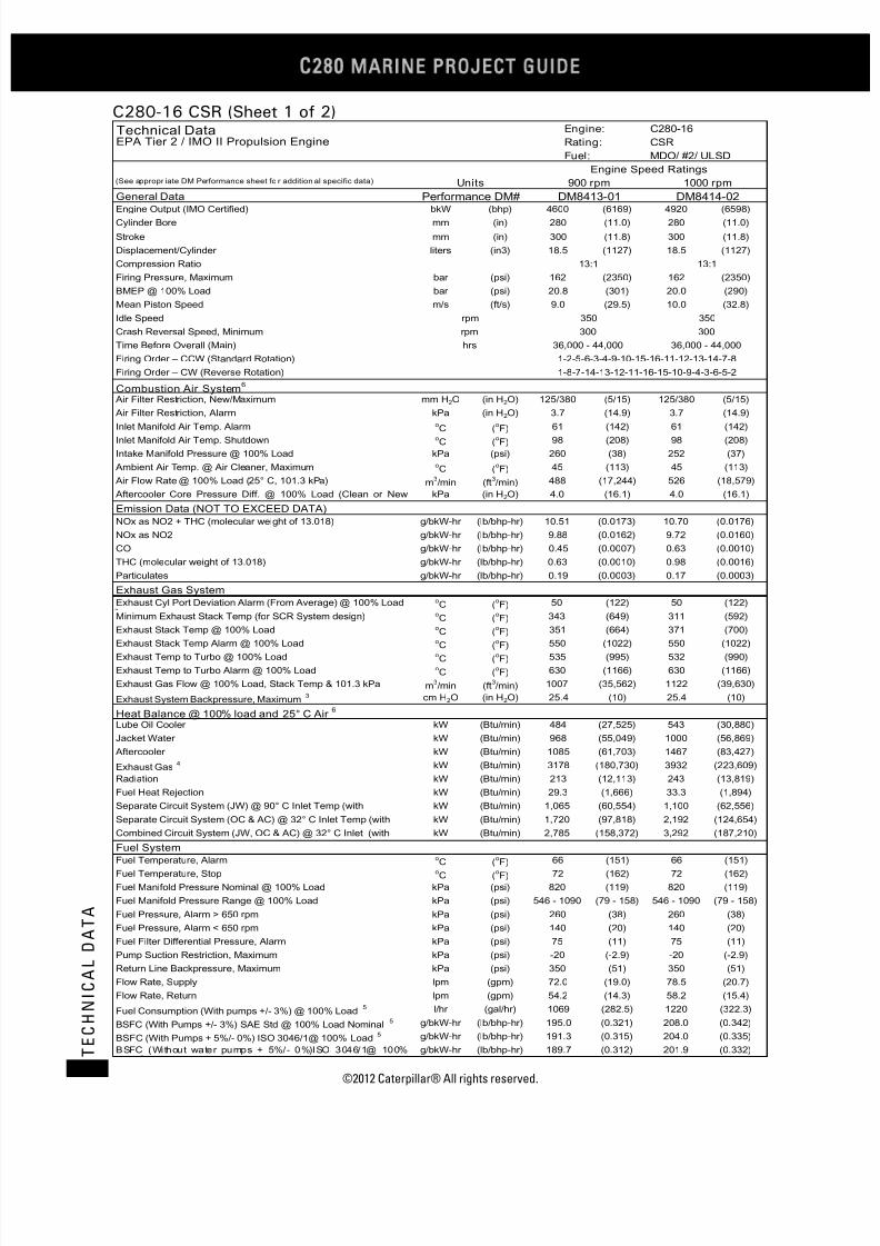
7/23/2019 1.- c280 Epa Tier 2 - Imo II Marine Project Guide
http://slidepdf.com/reader/full/1-c280-epa-tier-2-imo-ii-marine-project-guide 44/222
C28
MARINE PROJECT GUIDE
©2012 Caterpillar® All rights reserved.36
T E C H N I C A L D A T A
C280-16 CSR (Sheet 1 of 2)
bkW (bhp) (6169) 4920 (6598)
mm (in) (11.0) 280 (11.0)
mm (in) (11.8) 300 (11.8)
liters (in3) (1127) 18.5 (1127)
bar (psi) (2350) 162 (2350)
bar (psi) (301) 20.0 (290)
m/s (ft/s) (29.5) 10.0 (32.8)
mm H2O (in H2O) (5/15) 125/380 (5/15)
kPa (in H2O) (14.9) 3.7 (14.9)
o
C (o
F) (142) 61 (142)oC (
oF) (208) 98 (208)
kPa (psi) (38) 252 (37)oC (
oF) (113) 45 (113)
m3/min (ft
3/min) (17,244) 526 (18,579)
kPa (in H2O) (16.1) 4.0 (16.1)
g/bkW-hr (lb/bhp-hr) (0.0173) 10.70 (0.0176)
g/bkW-hr (lb/bhp-hr) (0.0162) 9.72 (0.0160)
g/bkW-hr (lb/bhp-hr) (0.0007) 0.63 (0.0010)
g/bkW-hr (lb/bhp-hr) (0.0010) 0.98 (0.0016)
g/bkW-hr (lb/bhp-hr) (0.0003) 0.17 (0.0003)
oC (
oF) (122) 50 (122)
oC (
oF) (649) 311 (592)
oC (
oF) (664) 371 (700)
oC (oF) (1022) 550 (1022)oC (
oF) (995) 532 (990)
oC (
oF) (1166) 630 (1166)
m3/min (ft
3/min) (35,562) 1122 (39,630)
cm H2O (in H2O) (10) 25.4 (10)
kW (Btu/min) (27,525) 543 (30,880)
kW (Btu/min) (55,049) 1000 (56,869)
kW (Btu/min) (61,703) 1467 (83,427)
kW (Btu/min) (180,730) 3932 (223,609)
kW (Btu/min) (12,113) 243 (13,819)
kW (Btu/min) (1,666) 33.3 (1,894)
kW (Btu/min) (60,554) 1,100 (62,556)
kW (Btu/min) (97,818) 2,192 (124,654)
kW (Btu/min) (158,372) 3,292 (187,210)
oC (oF) (151) 66 (151)oC (
oF) (162) 72 (162)
kPa (psi) (119) 820 (119)
kPa (psi) (79 - 158) 546 - 1090 (79 - 158)
kPa (psi) (38) 260 (38)
kPa (psi) (20) 140 (20)
kPa (psi) (11) 75 (11)
kPa (psi) (-2.9) -20 (-2.9)
kPa (psi) (51) 350 (51)
lpm (gpm) (19.0) 78.5 (20.7)
lpm (gpm) (14.3) 58.2 (15.4)
l/hr (gal/hr) (282.5) 1220 (322.3)
g/bkW-hr (lb/bhp-hr) (0.321) 208.0 (0.342)
g/bkW-hr (lb/bhp-hr) (0.315) 204.0 (0.335)
g/bkW-hr (lb/bhp-hr) (0.312) 201.9 (0.332)BSFC (Without water pumps + 5%/- 0%)ISO 3046/1@ 100%
189.7
BSFC (With Pumps +/- 3%) SAE Std @ 100% Load Nominal5 195.0
BSFC (With Pumps + 5%/- 0%) ISO 3046/1@ 100% Load5 191.3
Flow Rate, Return 54.2
Fuel Consumption (With pumps +/- 3%) @ 100% Load5 1069
Return Line Backpressure, Maximum 350
Flow Rate, Supply 72.0
Fuel Filter Differential Pressure, Alarm 75
Pump Suction Restriction, Maximum -20
Fuel Pressure, Alarm > 650 rpm 260
Fuel Pressure, Alarm < 650 rpm 140
Fuel Manifold Pressure Nominal @ 100% Load 820
Fuel Manifold Pressure Range @ 100% Load 546 - 1090
Fuel System
Fuel Temperature, Alarm 66
Fuel Temperature, Stop 72
Separate Circuit System (OC & AC) @ 32° C Inlet Temp (with 1,720
Combined Circuit System (JW, OC & AC) @ 32° C Inlet (with 2,785
Fuel Heat Rejection 29.3
Separate Circuit System (JW) @ 90° C Inlet Temp (with 1,065
Exhaust Gas4 3178
Radiation 213
Jacket Water 968
Aftercooler 1085
Exhaust System Backpressure, Maximum3 25.4
Heat Balance @ 100% load and 25° C Air6
Lube Oil Cooler 484
Exhaust Temp to Turbo Alarm @ 100% Load 630
Exhaust Gas Flow @ 100% Load, Stack Temp & 101.3 kPa 1007
Exhaust Stack Temp Alarm @ 100% Load 550Exhaust Temp to Turbo @ 100% Load 535
Minimum Exhaust Stack Temp (for SCR System design) 343
Exhaust Stack Temp @ 100% Load 351
Particulates 0.19
Exhaust Gas System
Exhaust Cyl Port Deviation Alarm (From Average) @ 100% Load 50
CO 0.45
THC (molecular weight of 13.018) 0.63
Emission Data (NOT TO EXCEED DATA)
NOx as NO2 + THC (molecular weight of 13.018) 10.51
NOx as NO2 9.88
Air Flow Rate @ 100% Load (25° C, 101.3 kPa) 488
Aftercooler Core Pressure Diff. @ 100% Load (Clean or New 4.0
Intake Manifold Pressure @ 100% Load 260
Ambient Air Temp. @ Air Cleaner, Maximum 45
Inlet Manifold Air Temp. Alarm 61Inlet Manifold Air Temp. Shutdown 98
Combustion Air System6
Air Filter Restriction, New/Maximum 125/380
Air Filter Restriction, Alarm 3.7
Firing Order – CCW (Standard Rotation) 1-2-5-6-3-4-9-10-15-16-11-12-13-14-7-8
Firing Order – CW (Reverse Rotation) 1-8-7-14-13-12-11-16-15-10-9-4-3-6-5-2
Time Before Overall (Main) hrs 36,000 - 44,000 36,000 - 44,000
Crash Reversal Speed, Minimum rpm 300 300
Idle Speed rpm 350 350
BMEP @ 100% Load 20.8
Mean Piston Speed 9.0
Compression Ratio 13:1 13:1
Firing Pressure, Maximum 162
Stroke 300
Displacement/Cylinder 18.5
Engine Output (IMO Certified) 4600
Cylinder Bore 280
General Data Performance DM# DM8413-01 DM8414-02
(See appropr iate DM Performance sheet fo r addition al specific data) Units 900 rpm 1000 rpm
Fuel: MDO/ #2/ ULSD
Engine Speed Ratings
Technical Data Engine: C280-16
EPA Tier 2 / IMO II Propulsion Engine Rating: CSR

7/23/2019 1.- c280 Epa Tier 2 - Imo II Marine Project Guide
http://slidepdf.com/reader/full/1-c280-epa-tier-2-imo-ii-marine-project-guide 45/222
©2012 Caterpillar® All rights reserved. 37
T E C H N I C A L D A T A
C280-16 CSR (Sheet 2 of 2)
kPa (psi) (55) 380 (55)
kPa (psi) (46) 320 (46)
kPa (psi) (17) 120 (17)
kPa (psi) (38) 260 (38)
kPa (psi) (15) 105 (15)oC (
oF) (185) 85 (185)
oC (
oF) (198) 92 (198)
oC (
oF) (208) 98 (208)
kPa (psi) (15) 104 (15)
kPa (psi) (10) 70 (10)
kPa (psi) (24) 165 (24)
mm (in) (2) 50 (2)
liters (gal) (280) 1060 (280)
lpm (gpm) (295) 1117 (295)
lpm (gpm) (20) 76 (20)
lpm (gpm) (6) 23 (6)
l/hr (gal/hr) (0.94) 3.8 (1.00)
g/bkW-hr (lb/bhp-hr) (0.0012) 0.7 (0.0012)
oC (
oF) (181) 83 (181)
oC (
oF) (194) 90 (194)
oC (
oF) (203) 95 (203)
oC (
oF) (210) 99 (210)
oC (
oF) (217) 103 (217)
oC (
oF) (228) 109 (228)
kPa (psi) (4.4) 30 (4.4)
kPa (psi) (10) 70 (10)
kPa (psi) (34.8) 295 (42.8)
kPa (psi) (11.7) 103 (14.9)
lpm (gpm) (695) 2,920 (771)
oC (
oF) (90) 32 (90)
oC (
oF) (100) 38 (100)
oC (
oF) (102) 39 (102)
oC (
oF) (108) 42 (108)
kPa (psi) (-0.73) -5.0 (-0.73)
kPa (psi) (10) 70 (10)
kPa (psi) (35.5) 305 (44.2)
kPa (psi) (9.6) 85 (12.3)
kPa (psi) (9.6) 85 (12.3)
lpm (gpm) (412) 1730 (457)
bar (psi) (75) 5.2 (75)
bar (psi) (50) 3.4 (50)
bar (psi) (150) 10.4 (150)
bar (psi) (200) 13.8 (200)
Engine Power +/- 3%
Heat Rejection JW (Block) +/- 10%
Heat Rejection SCAC +/- 5%
Heat Rejection Radiant +/- 50%
Charge Air Pressure +/- 10%
Exhaust Flow +/- 5%
25° C (77° F)30° C (86° F) 40°C (104°F)45°C (113°F)50°C (122°F)
1.00 1.03 1.13 1.18 1.23
1.00 1.00 0.97 0.95 0.94
8 Normal variation in cylinder to cylinder exhaust port temperatures from the average of exhaust port temperatures for the engine.
9 Shallow oil pan is available for light weight option and dry sump option available where required.
10 For full by-pass flow pressure drop multiply by 130%
4 Exhaust heat rejection is based on fuel LHV to 25° C and is not normally recoverable in total
5 At 100% loads with pumps +/- 3% except where specified differently. Performance and fuel consumption are based on 35 API, 16° C fuel having a lower heating of 42,780 kJ/kg
used at 29° C with a density of 838.9 g/liter. Does not include sea water pump pa6 Air Flows are shown for 25° C air inlet to the turbocharger and 32° C cooling water to the charge air cooler. Adjust aftercooler heat load for higher ambients using the Aftercooler
Heat Rejection Factors.7 This engine's exhaust emissions are in compliance with the International Marine Organization's (IMO) standard as described in Regulation 13 of ANNEX VI of MARPOL, 73/79 and
ISO 8178 for measuring HC, CO, PM, NOx.
Notes1 Continuous prelube system requires lines group for continuous prelube (Contact factory if prelube not factory supplied)
2 Ratings are based on ISO 3046/1 and SAEJ1995 Jan 1990 standard reference conditions of 100 kPa, 25° C, and 30% relative humidity at the stated aftercooler water temperature
3 Contact Factory for applications needing additional limits
Correction Factor (Multiply by AC heat load) 1.08
Power Derate Factors 0.98
Inlet Air Flow +/- 5%Correction Factors (For Both Ratings) (Need to include in system heat load calculation if not @ 25° C ambient air temp)
Air to Turbo Temp. (Ambient Temp) 35°C (95° F)
Exhaust Stack Temperature +/- 8%
Fuel Rate +/- 5%
BSFC ISO 3046/1 + 5% / - 0%
Heat Rejection Oil Cooler (OC) +/- 20%
Tolerances
Specific Fuel Consumption +/- 3%
Air Pressure, Maximum Static Pressure (Dual Starter) 13.8
Air Pressure, minimum (Engine Only, Dual Starter) 3.4
Air Pressure, Maximum Dynamic Pressure (Dual Starter) 10.4
Pump Capacity (AC/OC Separate or JW, AC/OC Combined 1560
Starting Air System
Low Air Pressure, alarm 5.2
External Restriction Pressure Drop AC/OC Circuit (Full Flow)10 66
External Restriction JW, AC/OC Combined Circuit (Full Flow)10 66
AC/OC Water Pump Outlet Pressure, Alarm 70
Pump Rise (delta P) @ 32oC (90
oF) 245
Inlet Temp, Shutdown 42
Pump Inlet Pressure, Minimum -5.0
Inlet Temp, Maximum without derate3 38
Inlet Temp, Alarm 39
Pump Capacity (JW Circuit Only for Separate Circuit) 2,630
Cooling Water system – AC/OC Cooling
Inlet Temp, Nominal @ 27oC Sea Water Temp 32
Pump Rise (delta P) @ 85oC (185
oF) 240
External Restriction Pressure Drop (Full Flow)10 81
Pump Inlet Pressure, Minimum 30
Jacket Water Outlet Pressure, Alarm 70
Jacket Water Outlet Temperature, Alarm 103
Jacket Water Outlet Temperature, Shutdown 109
Inlet Temperature, Maximum 95
Outlet Temp before Regulator, Maximum 99
Cooling Water System – Block Cooling
Inlet Temperature, Minimum 83
Inlet Temperature, Nominal 90
Oil Consumption @ 100% load NOTE: May be higher at lower 3.5
BSOC @ 100% Load, Typical NOTE: Will be higher at lower 0.7
Prelube Pump Capacity, Intermittent 76
Prelube Pump Capacity, Continuous1 23
Sump Capacity (Marine Pan)9 1060
Lube Oil Flow 1117
Lube Oil Filter Differential Pressure, Shutdown 165
Lube Oil Sump Level, Alarm (Below Full Level) 50
Lube Oil Filter Differential Pressure, Maximum 104
Lube Oil Filter Differential Pressure, Alarm 70
Lube Oil Temperature, Alarm 92
Lube Oil Temperature, Shutdown 98
Lube Oil Pressure, Shutdown (0-650 rpm) 105
Lube Oil Temperature, Nominal 85
Lube Oil Pressure, Alarm (0-650 rpm) 120
Lube Oil Pressure, Shutdown (650-1000 rpm) 260
Lube Oil Pressure, Nominal 380
Lube Oil Pressure, Alarm (650-1000 rpm) 320
Lubricating Oil System Performance DM# DM8413-01 DM8414-02
(See appropriate DM Performance sheet for additional specific data) Units 900 rpm 1000 rpm
Fuel: MDO/ #2/ ULSD
Engine Speed Ratings
Technical Data Engine: C280-16
EPA Tier 2 / IMO II Propulsion Engine Rating: CSR
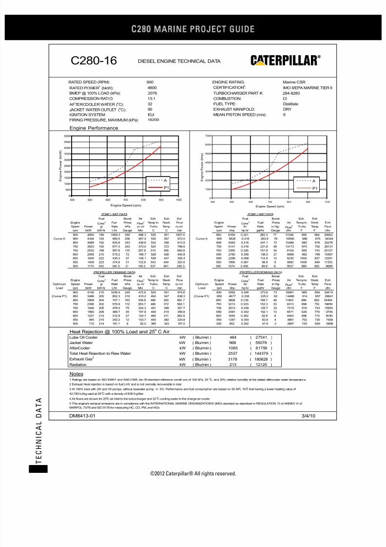
7/23/2019 1.- c280 Epa Tier 2 - Imo II Marine Project Guide
http://slidepdf.com/reader/full/1-c280-epa-tier-2-imo-ii-marine-project-guide 46/222
C28
MARINE PROJECT GUIDE
©2012 Caterpillar® All rights reserved.38
T E C H N I C A L D A T A
C280-16 DIESEL ENGINE TECHNICAL DATA
RATED SPEED (RPM): 900 ENGINE RATING: Marine CSR
RATED POWER (bkW):1 4600 CERTIFICATION :
5IMO II/EPA MARINE TIER II
BMEP @ 100% LOAD (kPa): 2076 TURBOCHARGER PART #: 284-8280COMPRESSION RATIO: 13:1 COMBUSTION: DI
AFTERCOOLER WATER (oC): 32 FUEL TYPE: Distillate
JACKET WATER OUTLET (oC): 90 EXHAUST MANIFOLD: DRY
IGNITION SYSTEM: EUI MEAN PISTON SPEED (m/s): 9
FIRING PRESSURE, MAXIMUM (kPa):
Engine Performance
ZONE LIMIT DATA ZONE LIMIT DATA
Fuel Boost Air Exh Exh Exh Fuel Boost Exh Exh
Engine Cons Fuel Press3Flow
4 Temp to Stack Flow Engine Cons Fuel Press3 Air Temp to Stack Exh
Speed Power g/ Rate kPa cu m/ Turbo Temp cu m/ Speed Power lb/ Rate in Hg- Flow4 Turbo Temp Flow
rpm bkW kW-hr L/hr Gauge Min C C min rpm bhp hp-hr gal/hr Gauge cfm F F cfm
900 4600 195 1069.3 260 488.3 535 351 1007.0 900 6169 0.321 282.3 77 17246 995 664 35563
Curve A 850 4344 193 999.5 256 467.4 530 357 972.5 Curve A 850 5826 0.318 263.9 76 16506 986 675 34344
800 4089 192 935.8 243 438.6 532 358 913.9 800 5483 0.316 247.1 72 15488 990 676 32276
750 3833 192 877.4 203 373.0 524 372 796.6 750 5141 0.316 231.6 60 13173 975 702 28131
700 2532 198 597.6 115 257.8 515 395 569.9 700 3395 0.326 157.8 34 9104 959 743 20127
650 2058 210 515.2 72 189.7 528 426 440.8 650 2760 0.346 136.0 21 6698 982 799 15567
600 1645 222 435.3 47 148.1 538 447 355.4 600 2206 0.366 114.9 14 5230 1000 837 12551
550 1409 223 374.6 31 132.6 543 454 320.9 550 1890 0.367 98.9 9 4683 1009 849 11333
500 1174 243 340.0 21 100.2 537 461 246.3 500 1574 0.400 89.8 6 3537 999 862 8698
PROPELLER DEMAND DAT A PROPELLER DEMAND DATA
Fuel Boost Air Exh Exh Exh Fuel Boost Exh Exh
EngineCons
Fuel Press3
Flow
4 Temp to Stack Flow EngineCons
Fuel Press3 Air Temp to Stack Exh
Optimum Speed Power g/ Rate kPa cu m/ Turbo Temp cu m/ Optimum Speed Power lb/ Rate in Hg- Flow4 Turbo Temp Flow
Load rpm bkW kW-hr L/hr Gauge Min C C min Load rpm bhp hp-hr gal/hr Gauge cfm F F cfm
900 4140 210 1036.4 245 472.6 520 351 974.6 900 5552 0.346 273.6 73 16691 968 664 34419
(Curve P1) 850 3488 205 852.3 210 410.2 490 347 839.3 (Curve P1) 850 4677 0.338 225.0 62 14486 914 657 29641
800 2908 204 707.1 163 336.8 480 350 692.7 800 3899 0.336 186.7 48 11895 896 662 24464
750 2396 202 576.9 112 263.7 480 372 562.1 750 3213 0.333 152.3 33 9313 896 702 19850
700 1948 205 476.0 75 204.3 491 395 451.7 700 2612 0.338 125.7 22 7215 916 743 15953
650 1560 208 386.7 45 157.8 498 415 359.8 650 2091 0.342 102.1 13 5571 928 779 12705
600 1227 214 312.9 27 124.7 480 411 282.9 600 1645 0.352 82.6 8 4404 896 772 9990
550 945 215 242.2 12 103.7 400 382 224.8 550 1267 0.354 63.9 4 3661 752 720 7938
500 710 214 181.1 8 82.0 385 343 167.0 500 952 0.352 47.8 2 2897 725 649 5898
Heat Rejection @ 100% Load and 25o C Air
Lube Oil Cooler kW ( Btu/min ) 484 ( 27541 )
Jacket Water kW ( Btu/min ) 968 ( 55079 )
AfterCooler kW ( Btu/min ) 1085 ( 61759 )
Total Heat Rejection to Raw Water kW ( Btu/min ) 2537 ( 144379 )
Exhaust Gas kW ( Btu/min ) 3178 ( 180828 )2
Radiation kW ( Btu/min ) 213 ( 12120 )
Notes1 Ratings are based on ISO 3046/1 and SAEJ1995 Jan 90 standard reference conditions of 100 kPa, 25 C, and 30% relative humidity at the stated aftercooler water temperature.
o
2 Exhaust Heat rejection is based on fuel LHV and is not normally recoverable in total
4 Air flows are shown for 25 C air inlet to the turbocharger and 32 C cooling water to the charge air cooler.o o
DM8413-01 3/4/10
3 At 100% load with JW and Oil pumps, without seawater pump, +/- 3%. Performance and fuel consumpt ion are based on 35 API, 16 C fuel having a lower heating value ofo
42,780 kJ/kg used at 29 C with a density of 838.9 g/liter.o
5 This engine's exhaust emissions are in compliance with the INTERNATIONAL MARINE ORGANIZATION'S (IMO) standard as described in REGULATION 13 of ANNEX VI of
MARPOL 73/78 and ISO 8178 for measuring HC, CO, PM, and NOx.
16200
0
500
1000
1500
2000
2500
3000
3500
4000
4500
5000
400 500 600 700 800 900 1000
Engine Speed (rpm)
E n g i n e P o w e r ( b k W )
A
P1
0
1000
2000
3000
4000
5000
6000
7000
400 500 600 700 800 900 1000
Engine Speed (rpm)
E n g i n e P o w e r ( b h p )
A
P1

7/23/2019 1.- c280 Epa Tier 2 - Imo II Marine Project Guide
http://slidepdf.com/reader/full/1-c280-epa-tier-2-imo-ii-marine-project-guide 47/222
©2012 Caterpillar® All rights reserved. 39
T E C H N I C A L D A T A
C280-16 DIESEL ENGINE TECHNICAL DATA
RATED SPEED (RPM): 1000 ENGINE RATING: Marine CSR
RATED POWER (bkW):1 4920 CERTIFICATION :
5IMO II/EPA MARINE TIER II
BMEP @ 100% LOAD (kPa): 1998 TURBOCHARGER PART #: 284-8276COMPRESSION RATIO: 13:1 COMBUSTION: DI
AFTERCOOLER WATER (oC): 32 FUEL TYPE: Distillate
JACKET WATER INLET (oC): 90 EXHAUST MANIFOLD: DRY
IGNITION SYSTEM: EUI MEAN PISTON SPEED (m/s): 10
FIRING PRESSURE, MAXIMUM (kPa):
Engine Performance
ZONE LIMIT DATA ZONE LIMIT DATA
Fuel Boost Air Exh Exh Exh Fuel Boost Exh Exh
Engine Cons Fuel Press3Flow
4 Temp to Stack Flow Engine Cons Fuel Press3 Air Temp to Stack Exh
Speed Power g/ Rate kPa cu m/ Turbo Temp cu m/ Speed Power lb/ Rate in Hg- Flow4 Turbo Temp Flow
rpm bkW kW-hr L/hr Gauge Min C C min rpm bhp hp-hr gal/hr Gauge cfm F F cfm
1000 4920 208 1222.0 252 526.1 532 371 1122.2 1000 6598 0.343 322.6 75 18580 989 701 39630
Curve A 950 4674 208 1159.8 249 506.3 533 365 1069.1 Curve A 950 6268 0.343 306.2 74 17880 992 689 37754
910 4477 208 1109.4 238 477.3 539 374 1021.4 910 6004 0.342 292.9 70 16855 1002 704 36071
850 4182 208 1034.9 209 418.3 563 408 944.9 850 5608 0.342 273.2 62 14771 1045 767 33368
800 2947 211 742.4 110 271.9 581 466 668.4 800 3952 0.348 196.0 33 9603 1078 871 23604
750 2424 215 622.0 74 206.6 608 504 535.9 750 3251 0.354 164.2 22 7297 1127 940 18925
700 1900 221 501.0 46 156.1 620 525 416.4 700 2548 0.364 132.3 13 5512 1148 977 14706
630 1520 226 410.1 28 119.7 626 529 321.8 630 2038 0.373 108.3 8 4227 1158 984 11364
600 1482 228 403.1 26 111.5 648 545 306.2 600 1987 0.376 106.4 8 3936 1199 1013 10814
500 1065 236 299.8 12 77.4 617 509 203.8 500 1428 0.389 79.2 4 2732 1142 948 7196
PROPELLER DEMAND DATA PROPELLER DEMAND DATA
Fuel Boost Air Exh Exh Exh Fuel Boost Exh Exh
Engine Cons Fuel Press3Flow
4 Temp to Stack Flow Engine Cons Fuel Press3 Air Temp to Stack Exh
Optimum Speed Power g/ Rate kPa cu m/ Turbo Temp cu m/ Optimum Speed Power lb/ Rate in Hg- Flow4 Turbo Temp Flow
Load rpm bkW kW-hr L/hr Gauge Min C C min Load rpm bhp hp-hr gal/hr Gauge cfm F F cfm
1000 4428 210 1108.5 238 508.2 520 365 1070.8 1000 5938 0.346 292.7 71 17946 968 688 37817
(Curve P1) 950 3796 212 959.4 197 449.7 523 377 965.0 (Curve P1) 950 5091 0.349 253.3 58 15880 974 710 34077
910 3337 211 839.3 154 372.1 530 402 830.9 910 4475 0.347 221.6 46 13141 986 756 29344
850 2719 211 684.0 100 272.9 549 445 649.6 850 3647 0.347 180.6 30 9638 1021 832 22941
800 2267 215 581.0 68 211.7 567 475 526.7 800 3040 0.354 153.4 20 7475 1053 887 18602
750 1868 219 487.7 45 167.7 577 492 427.5 750 2505 0.361 128.8 13 5922 1071 918 15097
700 1519 222 401.9 30 135.4 569 487 343.2 700 2037 0.366 106.1 9 4781 1056 909 12121
630 1107 225 297.0 15 101.7 519 443 242.5 630 1485 0.370 78.4 5 3592 967 829 8566
600 956 229 261.1 11 90.2 489 415 206.8 600 1283 0.377 68.9 3 3187 913 779 7305
500 554 236 155.7 3 63.5 371 311 122.7 500 742 0.389 41.1 1 2241 700 591 4335
Heat Rejection @ 100% Load and 2 5o C Air
Lube Oil Cooler kW ( Btu/min ) 543 ( 30885 )
Jacket Water kW ( Btu/min ) 1000 ( 56886 )
AfterCooler kW ( Btu/min ) 1467 ( 83480 )
Total Heat Rejection to Raw Water kW ( Btu/min ) 3010 ( 171250 )
Exhaust Gas kW ( Btu/min ) 3932 ( 223731 )2
Radiation kW ( Btu/min ) 243 ( 13827 )
Notes1 Ratings are based on ISO 3046/1 and SAEJ1995 Jan 90 standard reference condit ions of 100 kPa, 25 C, and 30% relative humidity at the stated aftercooler water temperature.
o
2 Exhaust Heat rejection is based on fuel LHV and is not normally recoverable in total
4 Air flows are shown for 25 C air inlet to the turbocharger and 32 C cooling water to the charge air cooler.o o
DM8414-02 3/4/10
3 At 100% load with JW and Oil pumps, without seawater pump, +/- 3%. Performance and fuel consumpt ion are based on 35 API, 16 C fuel having a lower heating value ofo
42,780 kJ/kg used at 29 C with a density of 838.9 g/liter.o
5 This engine's exhaust emissions are in compliance with the INTERNATIONAL MARINE ORGANIZATION'S (IMO) standard as described in REGULATION 13 of ANNEX VI of
MARPOL 73/78 and ISO 8178 for measuring HC, CO, PM, and NOx.
16200
0
1000
2000
3000
4000
5000
6000
400 500 600 700 800 900 1000 1100
Engine Speed (rpm)
E n g i n e P o w e r ( b k W )
A
P1
0
1000
2000
3000
4000
5000
6000
7000
400 500 600 700 800 900 1000 1100
Engine Speed (rpm)
E n g i n e P o w e r ( b h p )
A
P1

7/23/2019 1.- c280 Epa Tier 2 - Imo II Marine Project Guide
http://slidepdf.com/reader/full/1-c280-epa-tier-2-imo-ii-marine-project-guide 48/222
C28
MARINE PROJECT GUIDE
©2012 Caterpillar® All rights reserved.40
T E C H N I C A L D A T A
C280-16 MCR (Sheet 1 of 2)
bkW (bhp) (6786) 5420 (7268)mm (in) (11.0) 280 (11.0)
mm (in) (11.8) 300 (11.8)
liters (in3) (1127) 18.5 (1127)
bar (psi) (2509) 173 (2509)
bar (psi) (331) 22.0 (319)
m/s (ft/s) (29.5) 10.0 (32.8)
mm H2O (in H2O) (5/15) 125/380 (5/15)
kPa (in H2O) (14.9) 3.7 (14.9)o
C (o
F) (142) 61 (142)oC (
oF) (208) 98 (208)
kPa (psi) (40) 271 (39)oC (
oF) (113) 45 (113)
m3/min (ft
3/min) (18,219) 547 (19,314)
kPa (in H2O) (16.1) 4.0 (16.1)
g/bkW-hr (lb/bhp-hr) (0.0173) 10.70 (0.0176)
g/bkW-hr (lb/bhp-hr) (0.0162) 9.72 (0.0160)
g/bkW-hr (lb/bhp-hr) (0.0007) 0.63 (0.0010)
g/bkW-hr (lb/bhp-hr) (0.0010) 0.98 (0.0016)
g/bkW-hr (lb/bhp-hr) (0.0003) 0.17 (0.0003)
oC (
oF) (122) 50 (122)
oC (
oF) (644) 320 (608)
oC (
oF) (667) 373 (703)
oC (oF) (1022) 550 (1022)oC (
oF) (997) 543 (1009)
oC (
oF) (1166) 630 (1166)
m3/min (ft
3/min) (37,727) 1170 (41,311)
cm H2O (in H2O) (10) 25.4 (10)
kW (Btu/min) (28,946) 567 (32,245)
kW (Btu/min) (58,348) 1074 (61,077)
kW (Btu/min) (76,887) 1561 (88,773)
kW (Btu/min) (192,843) 4122 (234,414)
kW (Btu/min) (13,250) 262 (14,900)
kW (Btu/min) (1,666) 33.3 (1,894)
kW (Btu/min) (64,182) 1,181 (67,185)
kW (Btu/min) (115,467) 2,319 (131,905)
kW (Btu/min) (179,649) 3,501 (199,090)
oC (oF) (151) 66 (151)oC (
oF) (162) 72 (162)
kPa (psi) (119) 820 (119)
kPa (psi) (79 - 158) 546 - 1090 (79 - 158)
kPa (psi) (38) 260 (38)
kPa (psi) (20) 140 (20)
kPa (psi) (11) 75 (11)
kPa (psi) (-2.9) -20 (-2.9)
kPa (psi) (51) 350 (51)
lpm (gpm) (19.0) 78.5 (20.7)
lpm (gpm) (13.9) 56.6 (15.0)
l/hr (gal/hr) (309.1) 1312 (346.5)
g/bkW-hr (lb/bhp-hr) (0.319) 203.0 (0.334)
g/bkW-hr (lb/bhp-hr) (0.313) 199.1 (0.327)
g/bkW-hr (lb/bhp-hr) (0.311) 197.2 (0.324)BSFC (Without water pumps + 5%/- 0%)ISO 3046/1@ 100%
188.9
BSFC (With Pumps +/- 3%) SAE Std @ 100% Load Nominal5 194.0
BSFC (With Pumps + 5%/- 0%) ISO 3046/1@ 100% Load5 190.3
Flow Rate, Return 52.5
Fuel Consumption (With pumps +/- 3%) @ 100% Load5 1170
Return Line Backpressure, Maximum 350
Flow Rate, Supply 72.0
Fuel Filter Differential Pressure, Alarm 75
Pump Suction Restriction, Maximum -20
Fuel Pressure, Alarm > 650 rpm 260
Fuel Pressure, Alarm < 650 rpm 140
Fuel Manifold Pressure Nominal @ 100% Load 820
Fuel Manifold Pressure Range @ 100% Load 546 - 1090
Fuel System
Fuel Temperature, Alarm 66
Fuel Temperature, Stop 72
Separate Circuit System (OC & AC) @ 32° C Inlet Temp (with 2,030
Combined Circuit System (JW, OC & AC) @ 32° C Inlet (with 3,159
Fuel Heat Rejection 29.3
Separate Circuit System (JW) @ 90° C Inlet Temp (with 1,129
Exhaust Gas4 3391
Radiation 233
Jacket Water 1026
Aftercooler 1352
Exhaust System Backpressure, Maximum3 25.4
Heat Balance @ 100% load and 25° C Air6
Lube Oil Cooler 509
Exhaust Temp to Turbo Alarm @ 100% Load 630
Exhaust Gas Flow @ 100% Load, Stack Temp & 101.3 kPa 1068
Exhaust Stack Temp Alarm @ 100% Load 550Exhaust Temp to Turbo @ 100% Load 536
Minimum Exhaust Stack Temp (for SCR System design) 340
Exhaust Stack Temp @ 100% Load 353
Particulates 0.19
Exhaust Gas System
Exhaust Cyl Port Deviation Alarm (From Average) @ 100% Load 50
CO 0.45
THC (molecular weight of 13.018) 0.63
Emission Data (NOT TO EXCEED DATA)
NOx as NO2 + THC (molecular weight of 13.018) 10.51
NOx as NO2 9.88
Air Flow Rate @ 100% Load (25° C, 101.3 kPa) 516
Aftercooler Core Pressure Diff. @ 100% Load (Clean or New 4.0
Intake Manifold Pressure @ 100% Load 276
Ambient Air Temp. @ Air Cleaner, Maximum 45
Inlet Manifold Air Temp. Alarm 61Inlet Manifold Air Temp. Shutdown 98
Combustion Air System6
Air Filter Restriction, New/Maximum 125/380
Air Filter Restriction, Alarm 3.7
Firing Order – CCW (Standard Rotation) 1-2-5-6-3-4-9-10-15-16-11-12-13-14-7-8
Firing Order – CW (Reverse Rotation) 1-8-7-14-13-12-11-16-15-10-9-4-3-6-5-2
Time Before Overall (Main) hrs 36,000 - 44,000 36,000 - 44,000
Crash Reversal Speed, Minimum rpm 300 300
Idle Speed rpm 350 350
BMEP @ 100% Load 22.8
Mean Piston Speed 9.0
Compression Ratio 13:1 13:1
Firing Pressure, Maximum 173
Stroke 300
Displacement/Cylinder 18.5
Engine Output (IMO Certified) 5060Cylinder Bore 280
General Data Performance DM# DM8415-01 DM8416-02
(See appropriate DM Performance sheet for additional specific data) Units 900 rpm 1000 rpm
Fuel: MDO/ #2/ ULSD
Engine Speed Ratings
Technical Data Engine: C280-16
EPA Tier 2 / IMO II Propulsion Engine Rating: MCR

7/23/2019 1.- c280 Epa Tier 2 - Imo II Marine Project Guide
http://slidepdf.com/reader/full/1-c280-epa-tier-2-imo-ii-marine-project-guide 49/222
©2012 Caterpillar® All rights reserved. 41
T E C H N I C A L D A T A
C280-16 MCR (Sheet 2 of 2)
kPa (psi) (55) 380 (55)
kPa (psi) (46) 320 (46)
kPa (psi) (17) 120 (17)
kPa (psi) (38) 260 (38)
kPa (psi) (15) 105 (15)oC (
oF) (185) 85 (185)
oC (
oF) (198) 92 (198)
oC (
oF) (208) 98 (208)
kPa (psi) (15) 104 (15)
kPa (psi) (10) 70 (10)
kPa (psi) (24) 165 (24)
mm (in) (2) 50 (2)
liters (gal) (280) 1060 (280)
lpm (gpm) (295) 1117 (295)
lpm (gpm) (20) 76 (20)
lpm (gpm) (6) 23 (6)
l/hr (gal/hr) (1.03) 4.2 (1.10)
g/bkW-hr (lb/bhp-hr) (0.0012) 0.7 (0.0012)
oC (
oF) (181) 83 (181)
oC (
oF) (194) 90 (194)
oC (
oF) (203) 95 (203)
oC (
oF) (210) 99 (210)
oC (
oF) (217) 103 (217)
oC (
oF) (228) 109 (228)
kPa (psi) (4.4) 30 (4.4)
kPa (psi) (10) 70 (10)
kPa (psi) (34.8) 295 (42.8)
kPa (psi) (11.7) 103 (14.9)
lpm (gpm) (695) 2,920 (771)
oC (
oF) (90) 32 (90)
oC (
oF) (100) 38 (100)
oC (
oF) (102) 39 (102)
oC (
oF) (108) 42 (108)
kPa (psi) (-0.73) -5.0 (-0.73)
kPa (psi) (10) 70 (10)
kPa (psi) (35.5) 305 (44.2)
kPa (psi) (9.6) 85 (12.3)
kPa (psi) (9.6) 85 (12.3)
lpm (gpm) (412) 1730 (457)
bar (psi) (75) 5.2 (75)
bar (psi) (50) 3.4 (50)
bar (psi) (150) 10.4 (150)
bar (psi) (200) 13.8 (200)
Engine Power +/- 3%
Heat Rejection JW (Block) +/- 10%
Heat Rejection SCAC +/- 5%
Heat Rejection Radiant +/- 50%
Charge Air Pressure +/- 10%
Exhaust Flow +/- 5%
25° C (77° F)30° C (86° F) 40°C (104°F) 5°C (113°F 50°C (122°F)
1.00 1.03 1.13 1.18 1.23
1.00 1.00 0.97 0.95 0.94
8 Normal variation in cylinder to cylinder exhaust port temperatures from the average of exhaust port temperatures for the engine.
9 Shallow oil pan is available for light weight option and dry sump option available where required.
10 For full by-pass flow pressure drop multiply by 130%
4 Exhaust heat rejection is based on fuel LHV to 25° C and is not normally recoverable in total
5 At 100% loads with pumps +/- 3% except where specified differently. Performance and fuel consumption are based on 35 API, 16° C fuel having a lower heating of 42,780 kJ/kg
used at 29° C with a density of 838.9 g/liter. Does not include sea water pump pa6 Air Flows are shown for 25° C air inlet to the turbocharger and 32° C cooling water to the charge air cooler. Adjust aftercooler heat load for higher ambients using the Aftercooler
Heat Rejection Factors.7 This engine's exhaust emissions are in compliance with the International Marine Organization's (IMO) standard as described in Regulation 13 of ANNEX VI of MARPOL, 73/79 and
ISO 8178 for measuring HC, CO, PM, NOx.
Notes1 Continuous prelube system requires lines group for continuous prelube (Contact factory if prelube not factory supplied)
2 Ratings are based on ISO 3046/1 and SAEJ1995 Jan 1990 standard reference conditions of 100 kPa, 25° C, and 30% relative humidity at the stated aftercooler water temperature
3 Contact Factory for applications needing additional limits
Correction Factor (Multiply by AC heat load) 1.08
Power Derate Factors 0.98
Inlet Air Flow +/- 5%Correction Factors (For Both Ratings) (Need to include in system heat load calculation if not @ 25° C ambient air temp)
Air to Turbo Temp. (Ambient Temp) 35°C (95° F)
Exhaust Stack Temperature +/- 8%
Fuel Rate +/- 5%
BSFC ISO 3046/1 + 5% / - 0%
Heat Rejection Oil Cooler (OC) +/- 20%
Tolerances
Specific Fuel Consumption +/- 3%
Air Pressure, Maximum Static Pressure (Dual Starter) 13.8
Air Pressure, minimum (Engine Only, Dual Starter) 3.4
Air Pressure, Maximum Dynamic Pressure (Dual Starter) 10.4
Pump Capacity (AC/OC Separate or JW, AC/OC Combined 1560
Starting Air System
Low Air Pressure, alarm 5.2
External Restriction Pressure Drop AC/OC Circuit (Full Flow)10 66
External Restriction JW, AC/OC Combined Circuit (Full Flow)10 66
AC/OC Water Pump Outlet Pressure, Alarm 70
Pump Rise (delta P) @ 32oC (90
oF) 245
Inlet Temp, Shutdown 42
Pump Inlet Pressure, Minimum -5.0
Inlet Temp, Maximum without derate3 38
Inlet Temp, Alarm 39
Pump Capacity (JW Circuit Only for Separate Circuit) 2,630
Cooling Water syst em – AC/OC Cooling
Inlet Temp, Nominal @ 27oC Sea Water Temp 32
Pump Rise (delta P) @ 85oC (185
oF) 240
External Restriction Pressure Drop (Full Flow)10 81
Pump Inlet Pressure, Minimum 30
Jacket Water Outlet Pressure, Alarm 70
Jacket Water Outlet Temperature, Alarm 103
Jacket Water Outlet Temperature, Shutdown 109
Inlet Temperature, Maximum 95
Outlet Temp before Regulator, Maximum 99
Cooling Water System – Block Cooling
Inlet Temperature, Minimum 83
Inlet Temperature, Nominal 90
Oil Consumption @ 100% load NOTE: May be higher at lower 3.9
BSOC @ 100% Load, Typical NOTE: Will be higher at lower 0.7
Prelube Pump Capacity, Intermittent 76
Prelube Pump Capacity, Continuous1 23
Sump Capacity (Marine Pan)9 1060
Lube Oil Flow 1117
Lube Oil Filter Differential Pressure, Shutdown 165
Lube Oil Sump Level, Alarm (Below Full Level) 50
Lube Oil Filter Differential Pressure, Maximum 104
Lube Oil Filter Differential Pressure, Alarm 70
Lube Oil Temperature, Alarm 92
Lube Oil Temperature, Shutdown 98
Lube Oil Pressure, Shutdown (0-650 rpm) 105
Lube Oil Temperature, Nominal 85
Lube Oil Pressure, Alarm (0-650 rpm) 120
Lube Oil Pressure, Shutdown (650-1000 rpm) 260
Lube Oil Pressure, Nominal 380
Lube Oil Pressure, Alarm (650-1000 rpm) 320
Lubricating Oil System Performance DM# DM8415-01 DM8416-02
(See appropr iate DM Performance sheet for additional specific data) Units 900 rpm 1000 rpm
Fuel: MDO/ #2/ ULSD
Engine Speed Ratings
Technical Data Engine: C280-16
EPA Tier 2 / IMO II Propulsion Engine Rating: MCR

7/23/2019 1.- c280 Epa Tier 2 - Imo II Marine Project Guide
http://slidepdf.com/reader/full/1-c280-epa-tier-2-imo-ii-marine-project-guide 50/222
C28
MARINE PROJECT GUIDE
©2012 Caterpillar® All rights reserved.42
T E C H N I C A L D A T A
C280-16 DIESEL ENGINE TECHNICAL DATA
RATED SPEED (RPM): 900 ENGINE RATING: Marine MCR
RATED POWER (bkW):1 5060 CERTIFICATION :
5IMO II/EPA MARINE TIER II
BMEP @ 100% LOAD (kPa): 2283 TURBOCHARGER PART #: 284-8280COMPRESSION RATIO: 13:1 COMBUSTION: DI
AFTERCOOLER WATER (oC): 32 FUEL TYPE: Distillate
JACKET WATER OUTLET (oC): 90 EXHAUST MANIFOLD: DRY
IGNITION SYSTEM: EUI MEAN PISTON SPEED (m/s): 9
FIRING PRESSURE, MAXIMUM (kPa):
Engine Performance
ZONE LIMIT DATA ZONE LIMIT DATA
Fuel Boost Air Exh Exh Exh Fuel Boost Exh Exh
Engine Cons Fuel Press3Flow
4 Temp to Stack Flow Engine Cons Fuel Press3 Air Temp to Stack Exh
Speed Power g/ Rate kPa cu m/ Turbo Temp cu m/ Speed Power lb/ Rate in Hg- Flow4 Turbo Temp Flow
rpm bkW kW-hr L/hr Gauge Min C C min rpm bhp hp-hr gal/hr Gauge cfm F F cfm
900 5060 194 1170.2 276 515.9 536 353 1068.3 900 6785 0.319 309.0 82 18220 997 667 37728
Curve A 850 4779 197 1122.2 265 487.3 532 356 1014.4 Curve A 850 6408 0.324 296.3 79 17208 990 673 35823
800 4498 195 1045.5 256 458.5 530 365 967.8 800 6032 0.321 276.0 76 16192 986 689 34178
750 4217 193 970.1 230 405.4 524 381 878.0 750 5654 0.318 256.1 68 14315 975 718 31008
700 2833 196 661.9 137 284.4 515 428 659.5 700 3799 0.323 174.8 41 10044 959 802 23289
650 2408 200 574.0 91 216.3 539 473 536.3 650 3229 0.329 151.5 27 7639 1002 884 18938
600 1972 206 484.2 60 167.0 560 510 435.6 600 2644 0.339 127.8 18 5898 1040 950 15384
550 1636 224 436.8 38 138.9 580 539 376.8 550 2194 0.369 115.3 11 4907 1076 1002 13305
500 1300 227 351.7 27 102.5 571 568 289.2 500 1743 0.374 92.8 8 3622 1060 1055 10214
PROPELLER DEMAND DAT A PROPELLER DEMAND DATA
Fuel Boost Air Exh Exh Exh Fuel Boost Exh Exh
EngineCons
Fuel Press3
Flow
4 Temp to Stack Flow EngineCons
Fuel Press3 Air Temp to Stack Exh
Optimum Speed Power g/ Rate kPa cu m/ Turbo Temp cu m/ Optimum Speed Power lb/ Rate in Hg- Flow4 Turbo Temp Flow
Load rpm bkW kW-hr L/hr Gauge Min C C min Load rpm bhp hp-hr gal/hr Gauge cfm F F cfm
900 4302 205 1051.3 250 481.7 522 342 979.0 900 5769 0.338 277.6 74 17012 972 648 34572
(Curve P1) 850 3624 206 889.9 2215 424.8 505 346 868.0 (Curve P1) 850 4860 0.339 235.0 656 15002 941 655 30654
800 3021 202 727.5 165 349.9 484 340 707.9 800 4052 0.333 192.1 49 12356 903 644 24999
750 2490 201 596.5 120 274.4 486 363 576.7 750 3339 0.331 157.5 36 9691 907 685 20365
700 2024 204 493.1 81 211.4 494 398 469.5 700 2714 0.336 130.2 24 7465 921 748 16581
650 1621 209 403.5 47 162.1 501 412 368.1 650 2173 0.344 106.5 14 5723 934 774 13000
600 1275 214 325.2 27 128.8 488 414 293.6 600 1709 0.352 85.9 8 4550 910 777 10370
550 982 220 257.5 11 95.7 450 380 207.8 550 1317 0.362 68.0 3 3381 842 716 7338
500 738 227 199.6 9 83.2 425 363 175.3 500 989 0.374 52.7 3 2939 797 685 6192
Heat Rejection @ 100% Load and 25o C Air
Lube Oil Cooler kW ( Btu/min ) 509 ( 28971 )
Jacket Water kW ( Btu/min ) 1026 ( 58391 )
AfterCooler kW ( Btu/min ) 1352 ( 76941 )
Total Heat Rejection to Raw Water kW ( Btu/min ) 2888 ( 164303 )
Exhaust Gas kW ( Btu/min ) 3391 ( 192948 )2
Radiation kW ( Btu/min ) 233 ( 13258 )
Notes1 Ratings are based on ISO 3046/1 and SAEJ1995 Jan 90 standard reference conditions of 100 kPa, 25 C, and 30% relative humidity at the stated aftercooler water temperature.
o
2 Exhaust Heat rejection is based on fuel LHV and is not normally recoverable in total
4 Air flows are shown for 25 C air inlet to the turbocharger and 32 C cooling water to the charge air cooler.o o
DM8415-01 3/4/10
3 At 100% load with JW and Oil pumps, without seawater pump, +/- 3%. Performance and fuel consumpt ion are based on 35 API, 16 C fuel having a lower heating value ofo
42,780 kJ/kg used at 29 C with a density of 838.9 g/liter.o
5 This engine's exhaust emissions are in compliance with the INTERNATIONAL MARINE ORGANIZATION'S (IMO) standard as described in REGULATION 13 of ANNEX VI of
MARPOL 73/78 and ISO 8178 for measuring HC, CO, PM, and NOx.
17300
0
1000
2000
3000
4000
5000
6000
400 500 600 700 800 900 1000
Engine Speed (rpm)
E n g i n e P o w e r ( b k W )
A
P1
0
1000
2000
3000
4000
5000
6000
7000
8000
400 500 600 700 800 900 1000
Engine Speed (rpm)
E n g i n e P o w e r ( b h p )
A
P1

7/23/2019 1.- c280 Epa Tier 2 - Imo II Marine Project Guide
http://slidepdf.com/reader/full/1-c280-epa-tier-2-imo-ii-marine-project-guide 51/222
©2012 Caterpillar® All rights reserved. 43
T E C H N I C A L D A T A
C280-16 DIESEL ENGINE TECHNICAL DATA
RATED SPEED (RPM): 1000 ENGINE RATING: Marine MCR
RATED POWER (bkW):1 5420 CERTIFICATION :
5IMO II/EPA MARINE TIER II
BMEP @ 100% LOAD (kPa): 2201 TURBOCHARGER PART #: 284-8276COMPRESSION RATIO: 13:1 COMBUSTION: DI
AFTERCOOLER WATER (oC): 32 FUEL TYPE: Distillate
JACKET WATER INLET (oC): 90 EXHAUST MANIFOLD: DRY
IGNITION SYSTEM: EUI MEAN PISTON SPEED (m/s): 10
FIRING PRESSURE, MAXIMUM (kPa):
Engine Performance
ZONE LIMIT DATA ZONE LIMIT DATA
Fuel Boost Air Exh Exh Exh Fuel Boost Exh Exh
Engine Cons Fuel Press3Flow
4 Temp to Stack Flow Engine Cons Fuel Press3 Air Temp to Stack Exh
Speed Power g/ Rate kPa cu m/ Turbo Temp cu m/ Speed Power lb/ Rate in Hg- Flow4 Turbo Temp Flow
rpm bkW kW-hr L/hr Gauge Min C C min rpm bhp hp-hr gal/hr Gauge cfm F F cfm
1000 5420 203 1312.7 271 546.9 543 373 1169.8 1000 7268 0.335 346.6 80 19312 1009 703 41310
Curve A 950 5149 203 1245.8 273 528.6 537 361 1110.1 Curve A 950 6905 0.334 328.9 81 18666 999 682 39202
910 4932 203 1193.8 263 499.8 543 370 1064.0 910 6614 0.334 315.2 78 17651 1009 697 37574
850 4607 204 1118.7 233 439.9 573 410 996.5 850 6178 0.335 295.4 69 15535 1063 770 35193
800 3302 210 827.1 135 306.2 585 460 745.7 800 4428 0.346 218.4 40 10814 1085 859 26333
750 2721 213 692.3 92 230.2 619 505 597.4 750 3649 0.351 182.8 27 8130 1146 941 21096
700 2105 219 550.7 55 168.5 638 536 456.1 700 2823 0.361 145.4 16 5950 1181 997 16107
630 1612 226 434.3 31 123.8 645 545 339.7 630 2162 0.372 114.7 9 4373 1194 1013 11997
600 1559 228 423.5 28 114.6 668 561 321.2 600 2090 0.375 111.8 8 4047 1234 1041 11344
500 1159 236 326.2 14 80.0 661 545 220.9 500 1554 0.389 86.1 4 2825 1222 1013 7803
PROPELLER DEMAND DATA PROPELLER DEMAND DATA
Fuel Boost Air Exh Exh Exh Fuel Boost Exh Exh
Engine Cons Fuel Press3Flow
4 Temp to Stack Flow Engine Cons Fuel Press3 Air Temp to Stack Exh
Optimum Speed Power g/ Rate kPa cu m/ Turbo Temp cu m/ Optimum Speed Power lb/ Rate in Hg- Flow4 Turbo Temp Flow
Load rpm bkW kW-hr L/hr Gauge Min C C min Load rpm bhp hp-hr gal/hr Gauge cfm F F cfm
1000 4608 208 1142.5 244 510.5 523 367 1080.8 1000 6179 0.342 301.7 72 18030 974 693 38167
(Curve P1) 950 3951 210 989.0 207 462.1 526 375 988.5 (Curve P1) 950 5298 0.346 261.1 61 16318 978 707 34910
910 3472 208 861.0 165 387.4 531 398 859.8 910 4657 0.342 227.3 49 13681 988 749 30364
850 2830 211 711.8 107 283.9 551 442 673.5 850 3795 0.347 187.9 32 10027 1023 828 23786
800 2359 214 601.8 73 219.2 571 475 545.6 800 3164 0.352 158.9 22 7742 1059 887 19267
750 1944 218 505.2 49 172.5 584 496 442.1 750 2607 0.359 133.4 15 6091 1083 925 15612
700 1581 222 418.3 32 138.6 579 495 355.1 700 2120 0.366 110.4 10 4894 1074 923 12540
630 1152 227 311.8 17 103.6 532 453 251.1 630 1545 0.374 82.3 5 3660 990 848 8869
600 995 229 271.7 12 91.8 502 426 213.9 600 1335 0.377 71.7 4 3242 936 798 7553
500 576 235 161.4 3 63.9 383 320 125.7 500 772 0.387 42.6 1 2257 721 608 4440
Heat Rejection @ 100% Load and 25o C Air
Lube Oil Cooler kW ( Btu/min ) 567 ( 32289 )
Jacket Water kW ( Btu/min ) 1074 ( 61104 )
AfterCooler kW ( Btu/min ) 1561 ( 88832 )
Total Heat Rejection to Raw Water kW ( Btu/min ) 3203 ( 182225 )
Exhaust Gas kW ( Btu/min ) 4122 ( 234542 )2
Radiation kW ( Btu/min ) 262 ( 14908 )
Notes1 Ratings are based on ISO 3046/1 and SAEJ1995 Jan 90 standard reference condit ions of 100 kPa, 25 C, and 30% relative humidity at the stated aftercooler water temperature.
o
2 Exhaust Heat rejection is based on fuel LHV and is not normally recoverable in total
4 Air flows are shown for 25 C air inlet to the turbocharger and 32 C cooling water to the charge air cooler.o o
DM8416-02 3/4/10
3 At 100% load with JW and Oil pumps, without seawater pump, +/- 3%. Performance and fuel consumpt ion are based on 35 API, 16 C fuel having a lower heating value ofo
42,780 kJ/kg used at 29 C with a density of 838.9 g/liter.o
5 This engine's exhaust emissions are in compliance with the INTERNATIONAL MARINE ORGANIZATION'S (IMO) standard as described in REGULATION 13 of ANNEX VI of
MARPOL 73/78 and ISO 8178 for measuring HC, CO, PM, and NOx.
17300
0
1000
2000
3000
4000
5000
6000
400 500 600 700 800 900 1000 1100
Engine Speed (rpm)
E n g i n e P o w e r ( b k W )
A
P1
0
1000
2000
3000
4000
5000
6000
7000
8000
400 500 600 700 800 900 1000 1100
Engine Speed (rpm)
E n g i n e P o w e r ( b h p )
A
P1

7/23/2019 1.- c280 Epa Tier 2 - Imo II Marine Project Guide
http://slidepdf.com/reader/full/1-c280-epa-tier-2-imo-ii-marine-project-guide 52/222
C28
MARINE PROJECT GUIDE
©2012 Caterpillar® All rights reserved.44
T E C H N I C A L D A T A
C280-16 FCVR (Sheet 1 of 2)
bkW (bhp) 5650 (7577)
mm (in) 280 (11.0)
mm (in) 300 (11.8)
liters (in3) 18.5 (1127)
bar (psi) 173 (2509)
bar (psi) 22.9 (333)
m/s (ft/s) 10.0 (32.8)
mm H2O (in H2O) 125/380 (5/15)
kPa (in H2O) 3.7 (14.9)o
C (o
F) 61 (142)oC (
oF) 98 (208)
kPa (psi) 284 (41)oC (
oF) 45 (113)
m3/min (ft
3/min) 567 (20,006)
kPa (in H2O) 4.0 (16.1)
g/bkW-hr (lb/bhp-hr) 10.70 (0.0176)
g/bkW-hr (lb/bhp-hr) 9.72 (0.0160)
g/bkW-hr (lb/bhp-hr) 0.63 (0.0010)
g/bkW-hr (lb/bhp-hr) 0.98 (0.0016)
g/bkW-hr (lb/bhp-hr) 0.17 (0.0003)
oC (
oF) 50 (122)
oC (
oF) 328 (622)
oC (
oF) 377 (711)
oC (oF) 550 (1022)oC (
oF) 571 (1060)
oC (
oF) 630 (1166)
m3/min (ft
3/min) 1221 (43,123)
cm H2O (in H2O) 25.4 (10)
kW (Btu/min) 591 (33,610)
kW (Btu/min) 1120 (63,693)
kW (Btu/min) 1627 (92,526)
kW (Btu/min) 4297 (244,366)
kW (Btu/min) 273 (15,525)
kW (Btu/min) 33.3 (1,894)
kW (Btu/min) 1,232 (70,063)
kW (Btu/min) 2,418 (137,484)
kW (Btu/min) 3,650 (207,546)
oC (oF) 66 (151)oC (
oF) 72 (162)
kPa (psi) 820 (119)
kPa (psi) 546 - 1090 (79 - 158)
kPa (psi) 260 (38)
kPa (psi) 140 (20)
kPa (psi) 75 (11)
kPa (psi) -20 (-2.9)
kPa (psi) 350 (51)
lpm (gpm) 78.5 (20.7)
lpm (gpm) 55.0 (14.5)
l/hr (gal/hr) 1408 (371.9)
g/bkW-hr (lb/bhp-hr) 209.0 (0.344)
g/bkW-hr (lb/bhp-hr) 205.0 (0.337)
g/bkW-hr (lb/bhp-hr) 203.1 (0.334)
Technical Data Engine: C280-16
EPA Tier 2 / IMO II Propulsion Engine Rating: FCVR
Fuel: MDO/ #2/ ULSD
Engine Speed Ratings(See appropr iate DM Performance sheet for additional specific data) Units 900 rpm 1000 rpm
General Data Performance DM# DM8972-00Engine Output (IMO Certified)
Cylinder Bore
Stroke
Displacement/Cylinder
Compression Ratio 13:1
Firing Pressure, Maximum
BMEP @ 100% Load
Mean Piston Speed
Idle Speed rpm 350
Crash Reversal Speed, Minimum rpm 300
Time Before Overall (Main) hrs 36,000 - 44,000
Firing Order – CCW (Standard Rotation) 1-2-5-6-3-4-9-10-15-16-11-12-13-14-7-8
Firing Order – CW (Reverse Rotation) 1-8-7-14-13-12-11-16-15-10-9-4-3-6-5-2
Combustion Air System6
Air Filter Restriction, New/Maximum
Air Filter Restriction, Alarm
Inlet Manifold Air Temp. AlarmInlet Manifold Air Temp. Shutdown
Intake Manifold Pressure @ 100% Load
Ambient Air Temp. @ Air Cleaner, Maximum
Air Flow Rate @ 100% Load (25° C, 101.3 kPa)
Aftercooler Core Pressure Diff. @ 100% Load (Clean or New
Emission Data (NOT TO EXCEED DATA)
NOx as NO2 + THC (molecular weight of 13.018)
NOx as NO2
CO
THC (molecular weight of 13.018)
Particulates
Exhaust Gas System
Exhaust Cyl Port Deviation Alarm (From Average) @ 100% Load
Minimum Exhaust Stack Temp (for SCR System design)
Exhaust Stack Temp @ 100% Load
Exhaust Stack Temp Alarm @ 100% LoadExhaust Temp to Turbo @ 100% Load
Exhaust Temp to Turbo Alarm @ 100% Load
Exhaust Gas Flow @ 100% Load, Stack Temp & 101.3 kPa
Exhaust System Backpressure, Maximum3
Heat Balance @ 100% load and 25° C Air6
Lube Oil Cooler
Jacket Water
Aftercooler
Exhaust Gas4
Radiation
Fuel Heat Rejection
Separate Circuit System (JW) @ 90° C Inlet Temp (with
Separate Circuit System (OC & AC) @ 32° C Inlet Temp (with
Combined Circuit System (JW, OC & AC) @ 32° C Inlet (with
Fuel System
Fuel Temperature, Alarm
Fuel Temperature, Stop
Fuel Manifold Pressure Nominal @ 100% Load
Fuel Manifold Pressure Range @ 100% Load
Fuel Pressure, Alarm > 650 rpm
Fuel Pressure, Alarm < 650 rpm
Fuel Filter Differential Pressure, Alarm
Pump Suction Restriction, Maximum
Return Line Backpressure, Maximum
Flow Rate, Supply
Flow Rate, Return
Fuel Consumption (With pumps +/- 3%) @ 100% Load5
BSFC (With Pumps +/- 3%) SAE Std @ 100% Load Nominal5
BSFC (With Pumps + 5%/- 0%) ISO 3046/1@ 100% Load5
BSFC (Without water pumps + 5%/- 0%)ISO 3046/1@ 100%

7/23/2019 1.- c280 Epa Tier 2 - Imo II Marine Project Guide
http://slidepdf.com/reader/full/1-c280-epa-tier-2-imo-ii-marine-project-guide 53/222
©2012 Caterpillar® All rights reserved. 45
T E C H N I C A L D A T A
C280-16 FCVR (Sheet 2 of 2)
kPa (psi) 380 (55)
kPa (psi) 320 (46)
kPa (psi) 120 (17)
kPa (psi) 260 (38)
kPa (psi) 105 (15)
oC (
oF) 85 (185)
oC (
oF) 92 (198)
oC (
oF) 98 (208)
kPa (psi) 104 (15)
kPa (psi) 70 (10)
kPa (psi) 165 (24)
mm (in) 50 (2)
liters (gal) 1060 (280)
lpm (gpm) 1117 (295)
lpm (gpm) 76 (20)
lpm (gpm) 23 (6)
l/hr (gal/hr) 4.3 (1.15)
g/bkW-hr (lb/bhp-hr) 0.7 (0.0012)
oC (
oF) 83 (181)
oC (
oF) 90 (194)
oC (
oF) 95 (203)
oC (
oF) 99 (210)
oC (
oF) 103 (217)
oC (
oF) 109 (228)
kPa (psi) 30 (4.4)
kPa (psi) 70 (10)
kPa (psi) 295 (42.8)
kPa (psi) 103 (14.9)
lpm (gpm) 2,920 (771)
oC (
oF) 32 (90)
oC (
oF) 38 (100)
oC (
oF) 39 (102)
oC (
oF) 42 (108)
kPa (psi) -5.0 (-0.73)
kPa (psi) 70 (10)
kPa (psi) 305 (44.2)
kPa (psi) 85 (12.3)
kPa (psi) 85 (12.3)
lpm (gpm) 1730 (457)
bar (psi) 5.2 (75)
bar (psi) 3.4 (50)
bar (psi) 10.4 (150)
bar (psi) 13.8 (200)
Engine Power +/- 3%
Heat Rejection JW (Block) +/- 10%
Heat Rejection SCAC +/- 5%
Heat Rejection Radiant +/- 50%
Charge Air Pressure +/- 10%
Exhaust Flow +/- 5%
25° C (77° F)30° C (86° F) 40°C (104°F) 5°C (113°F 50°C (122°F)
1.00 1.03 1.13 1.18 1.23
1.00 1.00 0.97 0.95 0.94
Technical Data Engine: C280-16
EPA Tier 2 / IMO II Propulsion Engine Rating: FCVR
Fuel: MDO/ #2/ ULSD
Engine Speed Ratings(See appropri ate DM Performance sheet for additional specific data) Units 900 rpm 1000 rpm
Lubricating Oil System Performance DM# DM8972-00Lube Oil Pressure, Nominal
Lube Oil Pressure, Alarm (650-1000 rpm)
Lube Oil Pressure, Alarm (0-650 rpm)
Lube Oil Pressure, Shutdown (650-1000 rpm)
Lube Oil Pressure, Shutdown (0-650 rpm)
Lube Oil Temperature, Nominal
Lube Oil Temperature, Alarm
Lube Oil Temperature, Shutdown
Lube Oil Filter Differential Pressure, Maximum
Lube Oil Filter Differential Pressure, Alarm
Lube Oil Filter Differential Pressure, Shutdown
Lube Oil Sump Level, Alarm (Below Full Level)
Sump Capacity (Marine Pan)9
Lube Oil Flow
Prelube Pump Capacity, Intermittent
Prelube Pump Capacity, Continuous1
Oil Consumption @ 100% load NOTE: May be higher at lower
BSOC @ 100% Load, Typical NOTE: Will be higher at lower
Cooling Water System – Block Cooling
Inlet Temperature, Minimum
Inlet Temperature, Nominal
Inlet Temperature, Maximum
Outlet Temp before Regulator, Maximum
Jacket Water Outlet Temperature, Alarm
Jacket Water Outlet Temperature, Shutdown
Pump Inlet Pressure, Minimum
Jacket Water Outlet Pressure, Alarm
Pump Rise (delta P) @ 85oC (185
oF)
External Restriction Pressure Drop (Full Flow)10
Pump Capacity (JW Circuit Only for Separate Circuit)
Cooling Water system – AC/OC Cooling
Inlet Temp, Nominal @ 27oC Sea Water Temp
Inlet Temp, Maximum without derate3
Inlet Temp, Alarm
Inlet Temp, Shutdown
Pump Inlet Pressure, Minimum
AC/OC Water Pump Outlet Pressure, Alarm
Pump Rise (delta P) @ 32oC (90
oF)
External Restriction Pressure Drop AC/OC Circuit (Full Flow)10
External Restriction JW, AC/OC Combined Circuit (Full Flow)10
Pump Capacity (AC/OC Separate or JW, AC/OC Combined
Starting Air System
Low Air Pressure, alarm
Air Pressure, minimum (Engine Only, Dual Starter)
Air Pressure, Maximum Dynamic Pressure (Dual Starter)
Air Pressure, Maximum Static Pressure (Dual Starter)
Tolerances
Specific Fuel Consumption +/- 3%
BSFC ISO 3046/1 + 5% / - 0%
Heat Rejection Oil Cooler (OC) +/- 20%
Exhaust Stack Temperature +/- 8%
Fuel Rate +/- 5%
Inlet Air Flow +/- 5%Correction Factors (For Both Ratings) (Need to include in system heat load calculation if not @ 25° C ambient air temp)
Air to Turbo Temp. (Ambient Temp) 35°C (95° F)
Correction Factor (Multiply by AC heat load) 1.08
Power Derate Factors 0.98
Notes1 Continuous prelube system requires lines group for continuous prelube (Contact factory if prelube not factory supplied)
2 Ratings are based on ISO 3046/1 and SAEJ1995 Jan 1990 standard reference conditions of 100 kPa, 25° C, and 30% relative humidity at the stated aftercooler water temperature
3 Contact Factory for applications needing additional limits
8 Normal variation in cylinder to cylinder exhaust port temperatures from the average of exhaust port temperatures for the engine.
9 Shallow oil pan is available for light weight option and dry sump option available where required.
10 For full by-pass flow pressure drop multiply by 130%
4 Exhaust heat rejection is based on fuel LHV to 25° C and is not normally recoverable in total
5 At 100% loads with pumps +/- 3% except where specified differently. Performance and fuel consumption are based on 35 API, 16° C fuel having a lower heating of 42,780 kJ/kg
used at 29° C with a density of 838.9 g/liter. Does not include sea water pump pa6 Air Flows are shown for 25° C air inlet to the turbocharger and 32° C cooling water to the charge air cooler. Adjust aftercooler heat load for higher ambients using the Aftercooler
Heat Rejection Factors.7 This engine's exhaust emissions are in compliance with the International Marine Organization's (IMO) standard as described in Regulation 13 of ANNEX VI of MARPOL, 73/79 and
ISO 8178 for measuring HC, CO, PM, NOx.

7/23/2019 1.- c280 Epa Tier 2 - Imo II Marine Project Guide
http://slidepdf.com/reader/full/1-c280-epa-tier-2-imo-ii-marine-project-guide 54/222
C28
MARINE PROJECT GUIDE
©2012 Caterpillar® All rights reserved.46
T E C H N I C A L D A T A
C280-16 DIESEL ENGINE TECHNICAL DATA
RATED SPEED (RPM): 1000 ENGINE RATING: Fast Vessel
RATED POWER (bkW):1 5650 CERTIFICATION :
5IMO II/EPA MARINE TIER II
BMEP @ 100% LOAD (kPa): 2294 TURBOCHARGER PART #: 284-8276COMPRESSION RATIO: 13:1 COMBUSTION: DI
AFTERCOOLER WATER (oC): 32 FUEL TYPE: Distillate
JACKET WATER INLET (oC): 90 EXHAUST MANIFOLD: DRY
IGNITION SYSTEM: EUI MEAN PISTON SPEED (m/s): 10
FIRING PRESSURE, MAXIMUM (kPa):
Engine Performance
ZONE LIMIT DATA ZONE LIMIT DATA
Fuel Boost Air Exh Exh Exh Fuel Boost Exh Exh
Engine Cons Fuel Press3Flow
4 Temp to Stack Flow Engine Cons Fuel Press3 Air Temp to Stack Exh
Speed Power g/ Rate kPa cu m/ Turbo Temp cu m/ Speed Power lb/ Rate in Hg- Flow4 Turbo Temp Flow
rpm bkW kW-hr L/hr Gauge Min C C min rpm bhp hp-hr gal/hr Gauge cfm F F cfm
1000 5650 209 1407.6 284 566.5 571 377 1221.1 1000 7577 0.344 371.6 84 20007 1060 711 43122
Curve A 950 5307 210 1328.5 283 546.0 568 370 1163.4 Curve A 950 7117 0.346 350.8 84 19282 1054 698 41087
910 5141 209 1280.8 275 530.0 549 372 1132.6 910 6894 0.344 338.2 81 18715 1020 702 39997
850 4720 211 1187.2 243 475.1 580 415 1084.1 850 6330 0.347 313.4 72 16778 1076 779 38284
800 3480 212 879.4 143 323.2 591 455 782.3 800 4667 0.349 232.2 42 11414 1096 851 27628
750 2810 214 716.8 96 244.7 623 510 638.6 750 3768 0.352 189.3 28 8642 1153 950 22553
700 2310 220 605.8 57 173.0 645 532 467.2 700 3098 0.362 159.9 17 6109 1193 990 16498
630 1632 224 435.8 32 128.3 646 543 350.7 630 2189 0.369 115.1 9 4530 1195 1009 12385
600 1496 227 404.8 27 116.5 672 571 329.6 600 2006 0.374 106.9 8 4113 1242 1060 11641
500 1160 240 331.9 15 81.0 663 549 224.9 500 1556 0.395 87.6 4 2861 1225 1020 7942
PROPELLER DEMAND DATA PROPELLER DEMAND DATA
Fuel Boost Air Exh Exh Exh Fuel Boost Exh Exh
Engine Cons Fuel Press3Flow
4 Temp to Stack Flow Engine Cons Fuel Press3 Air Temp to Stack Exh
Optimum Speed Power g/ Rate kPa cu m/ Turbo Temp cu m/ Optimum Speed Power lb/ Rate in Hg- Flow4 Turbo Temp Flow
Load rpm bkW kW-hr L/hr Gauge Min C C min Load rpm bhp hp-hr gal/hr Gauge cfm F F cfm
1000 5650 209 1407.6 284 566.5 571 377 1221.1 1000 7577 0.344 371.6 84 20007 1060 711 43122
(Curve P1) 950 4844 208 1201.1 198 541.8 575 388 1183.8 (Curve P1) 950 6496 0.342 317.1 59 19133 1067 730 41807
910 4258 210 1065.8 179 390.7 543 401 875.7 910 5710 0.346 281.4 53 13798 1009 754 30924
850 3470 212 876.9 123 289.5 545 453 701.2 850 4653 0.349 231.5 36 10222 1013 847 24762
800 2893 215 741.4 77 229.5 580 479 577.3 800 3879 0.354 195.7 23 8106 1076 894 20386
750 2384 220 625.1 55 181.4 591 504 472.6 750 3196 0.362 165.0 16 6407 1096 939 16690
700 1938 225 519.8 43 137.6 592 502 358.7 700 2599 0.370 137.2 13 4858 1098 936 12669
630 1413 226 380.6 21 108.0 541 463 266.8 630 1895 0.372 100.5 6 3815 1006 865 9420
600 1220 228 331.7 15 93.7 505 431 221.3 600 1637 0.375 87.6 4 3308 941 808 7816
500 706 234 197.0 2 60.8 390 328 122.1 500 947 0.385 52.0 1 2146 734 622 4313
Heat Rejection @ 100% Load and 25o C Air
Lube Oil Cooler kW ( Btu/min ) 567 ( 32289 )
Jacket Water kW ( Btu/min ) 1074 ( 61104 )
AfterCooler kW ( Btu/min ) 1561 ( 88832 )
Total Heat Rejection to Raw Water kW ( Btu/min ) 3203 ( 182225 )
Exhaust Gas kW ( Btu/min ) 4122 ( 234542 )2
Radiation kW ( Btu/min ) 262 ( 14908 )
Notes1 Ratings are based on ISO 3046/1 and SAEJ1995 Jan 90 standard reference condit ions of 100 kPa, 25 C, and 30% relative humidity at the stated aftercooler water temperature.
o
2 Exhaust Heat rejection is based on fuel LHV and is not normally recoverable in total
4 Air flows are shown for 25 C air inlet to the turbocharger and 32 C cooling water to the charge air cooler.o o
DM8972-00 4/10/07
3 At 100% load with JW and Oil pumps, without seawater pump, +/- 3%. Performance and fuel consumpt ion are based on 35 API, 16 C fuel having a lower heating value ofo
42,780 kJ/kg used at 29 C with a density of 838.9 g/liter.o
5 This engine's exhaust emissions are in compliance with the INTERNATIONAL MARINE ORGANIZATION'S (IMO) standard as described in REGULATION 13 of ANNEX VI of
MARPOL 73/78 and ISO 8178 for measuring HC, CO, PM, and NOx.
17300
0
1000
2000
3000
4000
5000
6000
400 500 600 700 800 900 1000 1100
Engine Speed (rpm)
E n g i n e P o w e r ( b k W )
A
P1
0
1000
2000
3000
4000
5000
6000
7000
8000
400 500 600 700 800 900 1000 1100
Engine Speed (rpm)
E n g i n e P o w e r ( b h p )
A
P1
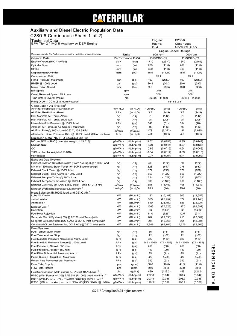
7/23/2019 1.- c280 Epa Tier 2 - Imo II Marine Project Guide
http://slidepdf.com/reader/full/1-c280-epa-tier-2-imo-ii-marine-project-guide 55/222
©2012 Caterpillar® All rights reserved. 47
T E C H N I C A L D A T A
Auxiliary and Diesel Electric Propulsion Data
C280-6 Continuous (Sheet 1 of 2)
bkW (bhp) (2320) 1850 (2481)
mm (in) (11.0) 280 (11.0)
mm (in) (11.8) 300 (11.8)
liters (in3) (1127) 18.5 (1127)
bar (psi) (2350) 162 (2350)
bar (psi) (301) 20.0 (290)
m/s (ft/s) (29.5) 10.0 (32.8)
mm H2O (in H2O) (5/15) 125/380 (5/15)
kPa (in H2O) (14.9) 3.7 (14.9)
oC (oF) (142) 61 (142)oC (
oF) (208) 98 (208)
kPa (psi) (51) 334 (48)oC (
oF) (113) 45 (113)
m3/min (ft
3/min) (6,332) 196 (6,925)
kPa (in H2O) (16.1) 4.0 (16.1)
g/bkW-hr (lb/bhp-hr) (0.0158) 8.95 (0.0147)
g/bkW-hr (lb/bhp-hr) (0.0145) 8.07 (0.0133)
g/bkW-hr (lb/bhp-hr) (0.0016) 0.54 (0.0009)
g/bkW-hr (lb/bhp-hr) (0.0014) 0.89 (0.0015)
g/bkW-hr (lb/bhp-hr) (0.0004) 0.21 (0.0003)
oC (
oF) (122) 50 (122)
oC (
oF) (613) 278 (532)
oC (
oF) (715) 376 (709)
oC (oF) (1022) 550 (1022)oC (
oF) (1029) 523 (973)
oC (
oF) (1166) 630 (1166)
m3/min (ft
3/min) (13,469) 405 (14,313)
cm H2O (in H2O) (10) 25.4 (10)
kW (Btu/min) (10,407) 205 (11,658)
kW (Btu/min) (20,757) 377 (21,440)
kW (Btu/min) (31,790) 586 (33,325)
kW (Btu/min) (77,626) 1470 (83,597)
kW (Btu/min) (4,891) 92 (5,232)
kW (Btu/min) (626) 12.5 (711)
kW (Btu/min) (22,833) 415 (23,584)
kW (Btu/min) (45,868) 861 (48,981)
kW (Btu/min) (68,701) 1,276 (72,565)
oC (oF) (151) 66 (151)oC (
oF) (162) 72 (162)
kPa (psi) (119) 820 (119)
kPa (psi) (79 - 158) 546 - 1090 (79 - 158)
kPa (psi) (38) 260 (38)
kPa (psi) (20) 140 (20)
kPa (psi) (11) 75 (11)
kPa (psi) (-2.9) -20 (-2.9)
kPa (psi) (51) 350 (51)
lpm (gpm) (10.0) 41.5 (11.0)
lpm (gpm) (8.2) 33.9 (8.9)
l/hr (gal/hr) (113.2) 458 (121.0)
g/bkW-hr (lb/bhp-hr) (0.342) 207.7 (0.342)
g/bkW-hr (lb/bhp-hr) (0.335) 203.7 (0.335)
g/bkW-hr (lb/bhp-hr) (0.328) 198.2 (0.326)
Technical Data Engine: C280-6
EPA Tier 2 / IMO II Auxiliary or DEP Engine Rating: Continuous
Fuel: MDO/ #2/ ULSD
Engine Speed Ratings(See appropr iate DM Performance sheet fo r addition al specific data) Units 900 rpm 1000 rpm
General Data Performance DM# DM8396-02 DM8395-02Engine Output (IMO Certified) 1730
Cylinder Bore 280
Stroke 300
Displacement/Cylinder 18.5
Compression Ratio 13:1 13:1
Firing Pressure, Maximum 162
BMEP @ 100% Load 20.8
Mean Piston Speed 9.0
Idle Speed rpm 350 350
Crash Reversal Speed, Minimum rpm 300 300
Time Before Overall (Main) hrs 36,000 - 44,000 36,000 - 44,000
Firing Order – CCW (Standard Rotation) 1-5-3-6-2-4
Combustion Air System6
Air Filter Restriction, New/Maximum 125/380
Air Filter Restriction, Alarm 3.7
Inlet Manifold Air Temp. Alarm 61
Inlet Manifold Air Temp. Shutdown 98
Intake Manifold Pressure @ 100% Load 348
Ambient Air Temp. @ Air Cleaner, Maximum 45
Air Flow Rate @ 100% Load (25° C, 101.3 kPa) 179
Aftercooler Core Pressure Diff. @ 100% Load (Clean or New 4.0
Emiss ion Data (NOT TO EXCEED DATA)
NOx as NO2 + THC (molecular weight of 13.018) 9.62
NOx as NO2 8.79
CO 0.96
THC (molecular weight of 13.018) 0.84
Particulates 0.27
Exhaust Gas System
Exhaust Cyl Port Deviation Alarm (From Average) @ 100% Load 50
Minimum Exhaust Stack Temp (for SCR System design) 323
Exhaust Stack Temp @ 100% Load 379
Exhaust Stack Temp Alarm @ 100% Load 550
Exhaust Temp to Turbo @ 100% Load 554
Exhaust Temp to Turbo Alarm @ 100% Load 630
Exhaust Gas Flow @ 100% Load, Stack Temp & 101.3 kPa 381
Exhaust System Backpressure, Maximum3 25.4
Heat Balance @ 100% load and 25° C Air6
Lube Oil Cooler 183
Jacket Water 365
Aftercooler 559
Exhaust Gas4 1365
Radiation 86
Fuel Heat Rejection 11.0
Separate Circuit System (JW) @ 90° C Inlet Temp (with 402
Separate Circuit System (OC & AC) @ 32° C Inlet Temp (with 807
Combined Circuit System (JW, OC & AC) @ 32° C Inlet (with 1,208
Fuel System
Fuel Temperature, Alarm 66
Fuel Temperature, Stop 72
Fuel Manifold Pressure Nominal @ 100% Load 820
Fuel Manifold Pressure Range @ 100% Load 546 - 1090
Fuel Pressure, Alarm > 650 rpm 260
Fuel Pressure, Alarm < 650 rpm 140
Fuel Filter Differential Pressure, Alarm 75
Pump Suction Restriction, Maximum -20
Return Line Backpressure, Maximum 350
Flow Rate, Supply 38.0
Flow Rate, Return 30.9
Fuel Consumption (With pumps +/- 3%) @ 100% Load5 429
BSFC (With Pumps +/- 3%) SAE Std @ 100% Load Nominal5 207.8
BSFC (With Pumps + 5%/- 0%) ISO 3046/1@ 100% Load5 203.8
BSFC (Without water pumps + 5%/- 0%)ISO 3046/1@ 100%
199.5

7/23/2019 1.- c280 Epa Tier 2 - Imo II Marine Project Guide
http://slidepdf.com/reader/full/1-c280-epa-tier-2-imo-ii-marine-project-guide 56/222
C28
MARINE PROJECT GUIDE
©2012 Caterpillar® All rights reserved.48
T E C H N I C A L D A T A
C280-6 Continuous (Sheet 2 of 2)
kPa (psi) (55) 380 (55)
kPa (psi) (46) 320 (46)kPa (psi) (17) 120 (17)
kPa (psi) (38) 260 (38)
kPa (psi) (15) 105 (15)oC (
oF) (185) 85 (185)
oC (
oF) (198) 92 (198)
oC (
oF) (208) 98 (208)
kPa (psi) (15) 104 (15)
kPa (psi) (10) 70 (10)
kPa (psi) (24) 165 (24)
mm (in) (2) 50 (2)
liters (gal) (184) 697 (184)
lpm (gpm) (152) 577 (152)
lpm (gpm) (20) 76 (20)
lpm (gpm) (6) 23 (6)
l/hr (gal/hr) (0.35) 1.4 (0.38)
g/bkW-hr (lb/bhp-hr) (0.0012) 0.7 (0.0012)
oC (
oF) (181) 83 (181)
oC (
oF) (194) 90 (194)
oC (
oF) (203) 95 (203)
oC (
oF) (210) 99 (210)
oC (
oF) (217) 103 (217)
oC (
oF) (228) 109 (228)
kPa (psi) (4.4) 30 (4.4)
kPa (psi) (10) 70 (10)
kPa (psi) (34.8) 295 (42.8)
kPa (psi) (11.2) 99 (14.4)
lpm (gpm) (347) 1,460 (386)
oC (
oF) (90) 32 (90)
oC (
oF) (100) 38 (100)
oC (
oF) (102) 39 (102)
oC (
oF) (108) 42 (108)
kPa (psi) (-0.73) -5.0 (-0.73)
kPa (psi) (10) 70 (10)
kPa (psi) (34.8) 295 (42.8)
kPa (psi) (12.2) 104 (15.1)
kPa (psi) (10.3) 91 (13.2)
lpm (gpm) (325) 1365 (361)
bar (psi) (75) 5.2 (75)
bar (psi) (60) 4.1 (60)
bar (psi) (120) 8.3 (120)
bar (psi) (200) 13.8 (200)
bar (psi) (40) 2.8 (40)
bar (psi) (90) 6.2 (90)
Engine Power +/- 3%
Heat Rejection JW (Block) +/- 10%
Heat Rejection SCAC +/- 5%
Heat Rejection Radiant +/- 50%
Charge Air Pressure +/- 10%
Exhaust Flow +/- 5%
25° C (77° F)30° C (86° F) 40°C (104°F) 5°C (113°F)50°C (122°F)
1.00 1.03 1.13 1.18 1.23
1.00 1.00 0.97 0.95 0.94
Technical Data Engine: C280-6
EPA Tier 2 / IMO II Auxili ary or DEP Engine Rating: Continuous
Fuel: MDO/ #2/ ULSD
Engine Speed Ratings(See appropriate DM Performance sheet for additional specific data) Units 900 rpm 1000 rpm
Lubricating Oil System Performance DM# DM8396-02 DM8395-02Lube Oil Pressure, Nominal 380
Lube Oil Pressure, Alarm (650-1000 rpm) 320Lube Oil Pressure, Alarm (0-650 rpm) 120
Lube Oil Pressure, Shutdown (650-1000 rpm) 260
Lube Oil Pressure, Shutdown (0-650 rpm) 105
Lube Oil Temperature, Nominal 85
Lube Oil Temperature, Alarm 92
Lube Oil Temperature, Shutdown 98
Lube Oil Filter Differential Pressure, Maximum 104
Lube Oil Filter Differential Pressure, Alarm 70
Lube Oil Filter Differential Pressure, Shutdown 165
Lube Oil Sump Level, Alarm (Below Full Level) 50
Sump Capacity (Marine Pan)9 697
Lube Oil Flow 577
Prelube Pump Capacity, Intermittent 76
Prelube Pump Capacity, Continuous1 23
Oil Consumption @ 100% load NOTE: May be higher at lower 1.3
BSOC @ 100% Load, Typical NOTE: Will be higher at lower 0.7
Cooling Water System – Block CoolingInlet Temperature, Minimum 83
Inlet Temperature, Nominal 90
Inlet Temperature, Maximum 95
Outlet Temp before Regulator, Maximum 99
Jacket Water Outlet Temperature, Alarm 103
Jacket Water Outlet Temperature, Shutdown 109
Pump Inlet Pressure, Minimum 30
Jacket Water Outlet Pressure, Alarm 70
Pump Rise (delta P) @ 85oC (185
oF) 240
External Restriction Pressure Drop (Full Flow)10 77
Pump Capacity (JW Circuit Only for Separate Circuit) 1,315
Cooling Water syst em – AC/OC Cooling
Inlet Temp, Nominal @ 27oC Sea Water Temp 32
Inlet Temp, Maximum without derate3 38
Inlet Temp, Alarm 39
Inlet Temp, Shutdown 42
Pump Inlet Pressure, Minimum -5.0
AC/OC Water Pump Outlet Pressure, Alarm 70
Pump Rise (delta P) @ 32oC (90
oF) 240
External Restriction Pressure Drop AC/OC Circuit (Full Flow)10 84
External Restriction JW, AC/OC Combined Circuit (Full Flow)10 71
Pump Capacity (AC/OC Separate or JW, AC/OC Combined 1230
Starting Air System
Low Air Pressure, alarm 5.2
Air Pressure, minimum (Engine Only, Std Starter) 4.1
Air Pressure, Maximum Dynamic Pressure (Standard Starter) 8.3
Air Pressure, Maximum Static Pressure (Standard or HD Starter) 13.8
Air Pressure, minimum (Engine Only, HD Starter) 2.8
Air Pressure, Maximum Dynamic Pressure (HD Starter) 6.2
Tolerances
Specific Fuel Consumption +/- 3%
BSFC ISO 3046/1 + 5% / - 0%
Heat Rejection Oil Cooler (OC) +/- 20%
Exhaust Stack Temperature +/- 8%
Fuel Rate +/- 5%
Inlet Air Flow +/- 5%Correction Factors (For Both Ratings) (Need to include in system heat load calculation if not @ 25° C ambient air temp)
Air to Turbo Temp. (Ambient Temp) 35°C (95° F)
Correction Factor (Multiply by AC heat load) 1.08
Power Derate Factors 0.98
Notes1 Continuous prelube system requires lines group for continuous prelube (Contact factory if prelube not factory supplied)
2 Ratings are based on ISO 3046/1 and SAEJ1995 Jan 1990 standard reference conditions of 100 kPa, 25° C, and 30% relative humidity at the stated aftercooler water temperature
3 Contact Factory for applications needing additional limits
8 Normal variation in cylinder to cylinder exhaust port temperatures from the average of exhaust port temperatures for the engine.
9 Shallow oil pan is available for light weight option and dry sump option available where required.
10 For full by-pass flow pressure drop multiply by 130%
4 Exhaust heat rejection is based on fuel LHV to 25° C and is not normally recoverable in total
5 At 100% loads with pumps +/- 3% except where specified differently. Performance and fuel consumption are based on 35 API, 16° C fuel having a lower heating of 42,780 kJ/kg
used at 29° C with a density of 838.9 g/liter. Does not include sea water pump pa6 Air Flows are shown for 25° C air inlet to the turbocharger and 32° C cooling water to the charge air cooler. Adjust aftercooler heat load for higher ambients using the Aftercooler
Heat Rejection Factors.7 This engine's exhaust emissions are in compliance with the International Marine Organization's (IMO) standard as described in Regulation 13 of ANNEX VI of MARPOL, 73/79 and
ISO 8178 for measuring HC, CO, PM, NOx.
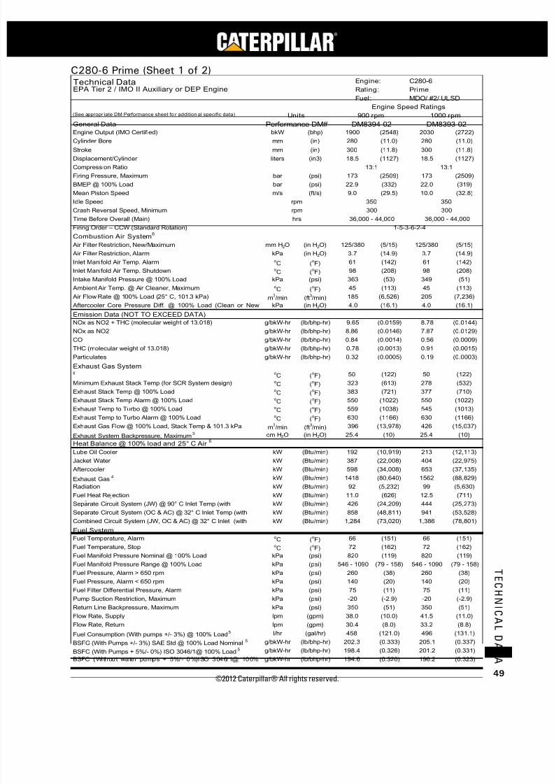
7/23/2019 1.- c280 Epa Tier 2 - Imo II Marine Project Guide
http://slidepdf.com/reader/full/1-c280-epa-tier-2-imo-ii-marine-project-guide 57/222
©2012 Caterpillar® All rights reserved. 49
T E C H N I C A L D A T A
C280-6 Prime (Sheet 1 of 2)
bkW (bhp) (2548) 2030 (2722)mm (in) (11.0) 280 (11.0)
mm (in) (11.8) 300 (11.8)
liters (in3) (1127) 18.5 (1127)
bar (psi) (2509) 173 (2509)
bar (psi) (332) 22.0 (319)
m/s (ft/s) (29.5) 10.0 (32.8)
mm H2O (in H2O) (5/15) 125/380 (5/15)
kPa (in H2O) (14.9) 3.7 (14.9)oC (
oF) (142) 61 (142)
oC (oF) (208) 98 (208)
kPa (psi) (53) 349 (51)oC (
oF) (113) 45 (113)
m3/min (ft
3/min) (6,526) 205 (7,236)
kPa (in H2O) (16.1) 4.0 (16.1)
g/bkW-hr (lb/bhp-hr) (0.0159) 8.78 (0.0144)
g/bkW-hr (lb/bhp-hr) (0.0146) 7.87 (0.0129)
g/bkW-hr (lb/bhp-hr) (0.0014) 0.56 (0.0009)
g/bkW-hr (lb/bhp-hr) (0.0013) 0.91 (0.0015)
g/bkW-hr (lb/bhp-hr) (0.0005) 0.19 (0.0003)
oC (
oF) (122) 50 (122)
oC (
oF) (613) 278 (532)
oC (
oF) (721) 377 (710)
oC (
oF) (1022) 550 (1022)
oC (
oF) (1038) 545 (1013)
oC (
oF) (1166) 630 (1166)
m3/min (ft
3/min) (13,978) 426 (15,037)
cm H2O (in H2O) (10) 25.4 (10)
kW (Btu/min) (10,919) 213 (12,113)
kW (Btu/min) (22,008) 404 (22,975)
kW (Btu/min) (34,008) 653 (37,135)
kW (Btu/min) (80,640) 1562 (88,829)
kW (Btu/min) (5,232) 99 (5,630)
kW (Btu/min) (626) 12.5 (711)
kW (Btu/min) (24,209) 444 (25,273)
kW (Btu/min) (48,811) 941 (53,528)
kW (Btu/min) (73,020) 1,386 (78,801)
o
C (o
F) (151) 66 (151)oC (
oF) (162) 72 (162)
kPa (psi) (119) 820 (119)
kPa (psi) (79 - 158) 546 - 1090 (79 - 158)
kPa (psi) (38) 260 (38)
kPa (psi) (20) 140 (20)
kPa (psi) (11) 75 (11)
kPa (psi) (-2.9) -20 (-2.9)
kPa (psi) (51) 350 (51)
lpm (gpm) (10.0) 41.5 (11.0)
lpm (gpm) (8.0) 33.2 (8.8)
l/hr (gal/hr) (121.0) 496 (131.1)
g/bkW-hr (lb/bhp-hr) (0.333) 205.1 (0.337)
g/bkW-hr (lb/bhp-hr) (0.326) 201.2 (0.331)
g/bkW-hr (lb/bhp-hr) (0.320) 196.2 (0.323)
Technical Data Engine: C280-6
EPA Tier 2 / IMO II Auxiliary or DEP Engine Rating: Prime
Fuel: MDO/ #2/ ULSD
Engine Speed Ratings(See appropr iate DM Performance sheet fo r addition al specific data) Units 900 rpm 1000 rpm
General Data Performance DM# DM8394-02 DM8393-02
Engine Output (IMO Certified) 1900Cylinder Bore 280
Stroke 300
Displacement/Cylinder 18.5
Compression Ratio 13:1 13:1
Firing Pressure, Maximum 173
BMEP @ 100% Load 22.9
Mean Piston Speed 9.0
Idle Speed rpm 350 350
Crash Reversal Speed, Minimum rpm 300 300
Time Before Overall (Main) hrs 36,000 - 44,000 36,000 - 44,000
Firing Order – CCW (Standard Rotation) 1-5-3-6-2-4
Combustion Air System6
Air Filter Restriction, New/Maximum 125/380
Air Filter Restriction, Alarm 3.7
Inlet Manifold Air Temp. Alarm 61
Inlet Manifold Air Temp. Shutdown 98
Intake Manifold Pressure @ 100% Load 363
Ambient Air Temp. @ Air Cleaner, Maximum 45
Air Flow Rate @ 100% Load (25° C, 101.3 kPa) 185
Aftercooler Core Pressure Diff. @ 100% Load (Clean or New 4.0
Emission Data (NOT TO EXCEED DATA)
NOx as NO2 + THC (molecular weight of 13.018) 9.65
NOx as NO2 8.86
CO 0.84
THC (molecular weight of 13.018) 0.78
Particulates 0.32
Exhaust Gas System 8 50
Minimum Exhaust Stack Temp (for SCR System design) 323
Exhaust Stack Temp @ 100% Load 383
Exhaust Stack Temp Alarm @ 100% Load 550
Exhaust Temp to Turbo @ 100% Load 559
Exhaust Temp to Turbo Alarm @ 100% Load 630
Exhaust Gas Flow @ 100% Load, Stack Temp & 101.3 kPa 396
Exhaust System Backpressure, Maximum3 25.4
Heat Balance @ 100% load and 25° C Air6
Lube Oil Cooler 192
Jacket Water 387
Aftercooler 598
Exhaust Gas4 1418
Radiation 92
Fuel Heat Rejection 11.0
Separate Circuit System (JW) @ 90° C Inlet Temp (with 426
Separate Circuit System (OC & AC) @ 32° C Inlet Temp (with 858
Combined Circuit System (JW, OC & AC) @ 32° C Inlet (with 1,284
Fuel System
Fuel Temperature, Alarm 66Fuel Temperature, Stop 72
Fuel Manifold Pressure Nominal @ 100% Load 820
Fuel Manifold Pressure Range @ 100% Load 546 - 1090
Fuel Pressure, Alarm > 650 rpm 260
Fuel Pressure, Alarm < 650 rpm 140
Fuel Filter Differential Pressure, Alarm 75
Pump Suction Restriction, Maximum -20
Return Line Backpressure, Maximum 350
Flow Rate, Supply 38.0
Flow Rate, Return 30.4
Fuel Consumption (With pumps +/- 3%) @ 100% Load5 458
BSFC (With Pumps +/- 3%) SAE Std @ 100% Load Nominal5 202.3
BSFC (With Pumps + 5%/- 0%) ISO 3046/1@ 100% Load5 198.4
BSFC (Without water pumps + 5%/- 0%)ISO 3046/1@ 100%
194.6

7/23/2019 1.- c280 Epa Tier 2 - Imo II Marine Project Guide
http://slidepdf.com/reader/full/1-c280-epa-tier-2-imo-ii-marine-project-guide 58/222
C28
MARINE PROJECT GUIDE
©2012 Caterpillar® All rights reserved.50
T E C H N I C A L D A T A
C280-6 Prime (Sheet 2 of 2)
kPa (psi) (55) 380 (55)
kPa (psi) (46) 320 (46)kPa (psi) (17) 120 (17)
kPa (psi) (38) 260 (38)
kPa (psi) (15) 105 (15)oC (
oF) (185) 85 (185)
oC (
oF) (198) 92 (198)
oC (
oF) (208) 98 (208)
kPa (psi) (15) 104 (15)
kPa (psi) (10) 70 (10)
kPa (psi) (24) 165 (24)
mm (in) (2) 50 (2)
liters (gal) (184) 697 (184)
lpm (gpm) (152) 577 (152)
lpm (gpm) (20) 76 (20)
lpm (gpm) (6) 23 (6)
l/hr (gal/hr) (0.39) 1.6 (0.41)
g/bkW-hr (lb/bhp-hr) (0.0012) 0.7 (0.0012)
oC (
oF) (181) 83 (181)
oC (
oF) (194) 90 (194)
oC (
oF) (203) 95 (203)
oC (
oF) (210) 99 (210)
oC (
oF) (217) 103 (217)
oC (
oF) (228) 109 (228)
kPa (psi) (4.4) 30 (4.4)
kPa (psi) (10) 70 (10)
kPa (psi) (34.8) 295 (42.8)
kPa (psi) (11.2) 99 (14.4)
lpm (gpm) (347) 1,460 (386)
oC (
oF) (90) 32 (90)
oC (
oF) (100) 38 (100)
oC (
oF) (102) 39 (102)
oC (
oF) (108) 42 (108)
kPa (psi) (-0.73) -5.0 (-0.73)
kPa (psi) (10) 70 (10)kPa (psi) (34.8) 295 (42.8)
kPa (psi) (12.2) 104 (15.1)
kPa (psi) (10.3) 91 (13.2)
lpm (gpm) (325) 1365 (361)
bar (psi) (75) 5.2 (75)
bar (psi) (60) 4.1 (60)
bar (psi) (120) 8.3 (120)
bar (psi) (200) 13.8 (200)
bar (psi) (40) 2.8 (40)
bar (psi) (90) 6.2 (90)
Engine Power +/- 3%
Heat Rejection JW (Block) +/- 10%
Heat Rejection SCAC +/- 5%
Heat Rejection Radiant +/- 50%
Charge Air Pressure +/- 10%
Exhaust Flow +/- 5%
25° C (77° F)30° C (86° F) 40°C (104°F) 5°C (113°F)50°C (122°F)
1.00 1.03 1.13 1.18 1.23
1.00 1.00 0.97 0.95 0.94
Technical Data Engine: C280-6
EPA Tier 2 / IMO II Auxiliary or DEP Engine Rating: Prime
Fuel: MDO/ #2/ ULSD
Engine Speed Ratings(See appropriate DM Performance sheet for additional sp ecific data) Units 900 rpm 1000 rpm
Lubricating Oil System Performance DM# DM8394-02 DM8393-02Lube Oil Pressure, Nominal 380
Lube Oil Pressure, Alarm (650-1000 rpm) 320Lube Oil Pressure, Alarm (0-650 rpm) 120
Lube Oil Pressure, Shutdown (650-1000 rpm) 260
Lube Oil Pressure, Shutdown (0-650 rpm) 105
Lube Oil Temperature, Nominal 85
Lube Oil Temperature, Alarm 92
Lube Oil Temperature, Shutdown 98
Lube Oil Filter Differential Pressure, Maximum 104
Lube Oil Filter Differential Pressure, Alarm 70
Lube Oil Filter Differential Pressure, Shutdown 165
Lube Oil Sump Level, Alarm (Below Full Level) 50
Sump Capacity (Marine Pan)9 697
Lube Oil Flow 577
Prelube Pump Capacity, Intermittent 76
Prelube Pump Capacity, Continuous1 23
Oil Consumption @ 100% load NOTE: May be higher at lower 1.5
BSOC @ 100% Load, Typical NOTE: Will be higher at lower 0.7
Cooling Water System – Block Cooli ng
Inlet Temperature, Minimum 83
Inlet Temperature, Nominal 90
Inlet Temperature, Maximum 95
Outlet Temp before Regulator, Maximum 99
Jacket Water Outlet Temperature, Alarm 103
Jacket Water Outlet Temperature, Shutdown 109
Pump Inlet Pressure, Minimum 30
Jacket Water Outlet Pressure, Alarm 70
Pump Rise (delta P) @ 85oC (185
oF) 240
External Restriction Pressure Drop (Full Flow)10 77
Pump Capacity (JW Circuit Only for Separate Circuit) 1,315
Cooling Water system – AC/OC Cooling
Inlet Temp, Nominal @ 27oC Sea Water Temp 32
Inlet Temp, Maximum without derate3 38
Inlet Temp, Alarm 39
Inlet Temp, Shutdown 42
Pump Inlet Pressure, Minimum -5.0
AC/OC Water Pump Outlet Pressure, Alarm 70
Pump Rise (delta P) @ 32oC (90
oF) 240
External Restriction Pressure Drop AC/OC Circuit (Full Flow)10 84
External Restriction JW, AC/OC Combined Circuit (Full Flow)10 71
Pump Capacity (AC/OC Separate or JW, AC/OC Combined 1230
Starting Air System
Low Air Pressure, alarm 5.2
Air Pressure, minimum (Engine Only, Std Starter) 4.1
Air Pressure, Maximum Dynamic Pressure (Standard Starter) 8.3
Air Max Static Pressure Reference (Standard or HD Starter) 13.8
Air Pressure, minimum (Engine Only, HD Starter) 2.8
Air Pressure, Maximum Dynamic Pressure (HD Starter) 6.2
Tolerances
Specific Fuel Consumption +/- 3%
BSFC ISO 3046/1 + 5% / - 0%
Heat Rejection Oil Cooler (OC) +/- 20%
Exhaust Stack Temperature +/- 8%Fuel Rate +/- 5%
Inlet Air Flow +/- 5%Correction Factors (For Both Ratings) (Need to include in system heat load calculation if not @ 25° C ambient air temp)
Air to Turbo Temp. (Ambient Temp) 35°C (95° F)
Correction Factor (Multiply by AC heat load) 1.08
Power Derate Factors 0.98
Notes1 Continuous prelube system requires lines group for continuous prelube (Contact factory if prelube not factory supplied)
2 Ratings are based on ISO 3046/1 and SAEJ1995 Jan 1990 standard reference conditions of 100 kPa, 25° C, and 30% relative humidity at the stated aftercooler water temperature
3 Contact Factory for applications needing additional limits
8 Normal variation in cylinder to cylinder exhaust port temperatures from the average of exhaust port temperatures for the engine.9 Shallow oil pan is available for light weight option and dry sump option available where required.
10 For full by-pass flow pressure drop multiply by 130%
4 Exhaust heat rejection is based on fuel LHV to 25° C and is not normally recoverable in total
At 100% loads with pumps +/- 3% except where specified differently. Performance and fuel consumption are based on 35 API, 16° C fuel having a lower heating of 42,780 kJ/kg
used at 29° C with a density of 838.9 g/liter. Does not include sea water pump pa
6 Air Flows are shown for 25° C air inlet to the turbocharger and 32° C cooling water to the charge air cooler. Adjust aftercooler heat load for higher ambients using the Aftercooler
Heat Rejection Factors.7 This engine's exhaust emissions are in compliance with the International Marine Organization's (IMO) standard as described in Regulation 13 of ANNEX VI of MARPOL, 73/79 and
ISO 8178 for measuring HC, CO, PM, NOx.
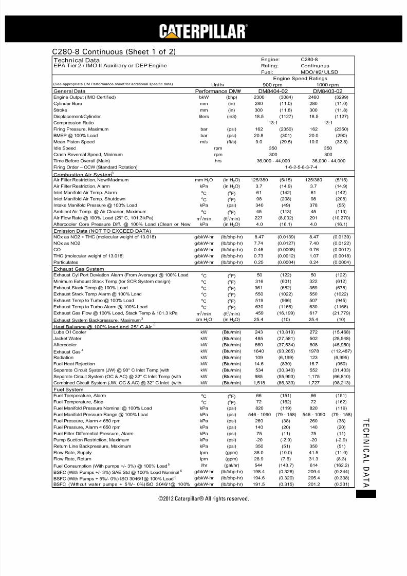
7/23/2019 1.- c280 Epa Tier 2 - Imo II Marine Project Guide
http://slidepdf.com/reader/full/1-c280-epa-tier-2-imo-ii-marine-project-guide 59/222
©2012 Caterpillar® All rights reserved. 51
T E C H N I C A L D A T A
C280-8 Continuous (Sheet 1 of 2)
bkW (bhp) (3084) 2460 (3299)mm (in) (11.0) 280 (11.0)
mm (in) (11.8) 300 (11.8)
liters (in3) (1127) 18.5 (1127)
bar (psi) (2350) 162 (2350)
bar (psi) (301) 20.0 (290)
m/s (ft/s) (29.5) 10.0 (32.8)
mm H2O (in H2O) (5/15) 125/380 (5/15)
kPa (in H2O) (14.9) 3.7 (14.9)oC (
oF) (142) 61 (142)
oC (oF) (208) 98 (208)
kPa (psi) (49) 378 (55)oC (
oF) (113) 45 (113)
m3/min (ft
3/min) (8,002) 291 (10,270)
kPa (in H2O) (16.1) 4.0 (16.1)
g/bkW-hr (lb/bhp-hr) (0.0139) 8.47 (0.0139)
g/bkW-hr (lb/bhp-hr) (0.0127) 7.40 (0.0122)
g/bkW-hr (lb/bhp-hr) (0.0008) 0.76 (0.0012)
g/bkW-hr (lb/bhp-hr) (0.0012) 1.07 (0.0018)
g/bkW-hr (lb/bhp-hr) (0.0004) 0.24 (0.0004)
oC (
oF) (122) 50 (122)
oC (
oF) (601) 322 (612)
oC (
oF) (682) 359 (678)
oC (
oF) (1022) 550 (1022)
oC (
oF) (966) 507 (945)
oC (
oF) (1166) 630 (1166)
m3/min (ft
3/min) (16,199) 617 (21,779)
cm H2O (in H2O) (10) 25.4 (10)
kW (Btu/min) (13,819) 272 (15,468)
kW (Btu/min) (27,581) 502 (28,548)
kW (Btu/min) (37,534) 808 (45,950)
kW (Btu/min) (93,265) 1978 (112,487)
kW (Btu/min) (6,199) 123 (6,995)
kW (Btu/min) (830) 16.7 (950)
kW (Btu/min) (30,340) 552 (31,403)
kW (Btu/min) (55,993) 1,175 (66,810)
kW (Btu/min) (86,333) 1,727 (98,213)
o
C (o
F) (151) 66 (151)oC (
oF) (162) 72 (162)
kPa (psi) (119) 820 (119)
kPa (psi) (79 - 158) 546 - 1090 (79 - 158)
kPa (psi) (38) 260 (38)
kPa (psi) (20) 140 (20)
kPa (psi) (11) 75 (11)
kPa (psi) (-2.9) -20 (-2.9)
kPa (psi) (51) 350 (51)
lpm (gpm) (10.0) 41.5 (11.0)
lpm (gpm) (7.6) 31.3 (8.3)
l/hr (gal/hr) (143.7) 614 (162.2)
g/bkW-hr (lb/bhp-hr) (0.326) 209.4 (0.344)
g/bkW-hr (lb/bhp-hr) (0.320) 205.4 (0.338)
g/bkW-hr (lb/bhp-hr) (0.315) 201.2 (0.331)
Flow Rate, Supply 38.0
Flow Rate, Return 28.9
Pump Suction Restriction, Maximum -20
Return Line Backpressure, Maximum 350
Fuel Pressure, Alarm < 650 rpm 140
Fuel Filter Differential Pressure, Alarm 75
Fuel Manifold Pressure Range @ 100% Load 546 - 1090
Fuel Pressure, Alarm > 650 rpm 260
Fuel Temperature, Stop 72
Fuel Manifold Pressure Nominal @ 100% Load 820
Separate Circuit System (JW) @ 90° C Inlet Temp (with 534
Separate Circuit System (OC & AC) @ 32° C Inlet Temp (with
Fuel Temperature, Alarm 66
985
Combined Circuit System (JW, OC & AC) @ 32° C Inlet (with 1,518
Fuel System
Radiation 109
Fuel Heat Rejection 14.6
Aftercooler 660
Exhaust Gas4 1640
Exhaust Gas Flow @ 100% Load, Stack Temp & 101.3 kPa 459
Exhaust System Backpressure, Maximum3
Jacket Water 485
25.4
Heat Balance @ 100% load and 25° C Air6
Lube Oil Cooler 243
Minimum Exhaust Stack Temp (for SCR System design) 316
Exhaust Stack Temp @ 100% Load
Exhaust Temp to Turbo Alarm @ 100% Load 630
361
Exhaust Stack Temp Alarm @ 100% Load 550
Exhaust Temp to Turbo @ 100% Load 519
0.46
THC (molecular weight of 13.018)
Exhaust Cyl Port Deviation Alarm (From Average) @ 100% Load 50
Exhaust Gas System
Time Before Overall (Main) hrs 36,000 - 44,000 36,000 - 44,000
Idle Speed rpm 350 350
BMEP @ 100% Load 20.8
Mean Piston Speed 9.0
Compression Ratio 13:1 13:1
Firing Pressure, Maximum 162
Stroke 300
Displacement/Cylinder 18.5
Cylinder Bore 280
General Data Performance DM# DM8404-02
900 rpm(See appropriate DM Performance sheet for additional specific data) Units 1000 rpm
Engine Output (IMO Certified) 2300
DM8403-02
Technical Data Engine: C280-8
EPA Tier 2 / IMO II Auxili ary or DEP Engine Rating: Continuous
Fuel Consumption (With pumps +/- 3%) @ 100% Load5 544
BSFC (With Pumps +/- 3%) SAE Std @ 100% Load Nominal5 198.4
Fuel:
Firing Order – CCW (Standard Rotation) 1-6-2-5-8-3-7-4
Combustion Air System6
Air Filter Restriction, New/Maximum 125/380
MDO/ #2/ ULSD
Crash Reversal Speed, Minimum rpm 300 300
Engine Speed Ratings
Air Filter Restriction, Alarm 3.7
Inlet Manifold Air Temp. Alarm 61
Inlet Manifold Air Temp. Shutdown 98
227
Aftercooler Core Pressure Diff. @ 100% Load (Clean or New 4.0
Intake Manifold Pressure @ 100% Load 340
Ambient Air Temp. @ Air Cleaner, Maximum 45
Emission Data (NOT TO EXCEED DATA)
Air Flow Rate @ 100% Load (25° C, 101.3 kPa)
0.73
Particulates 0.25
NOx as NO2 + THC (molecular weight of 13.018) 8.47
NOx as NO2 7.74
CO
BSFC (With Pumps + 5%/- 0%) ISO 3046/1@ 100% Load5 194.6
BSFC (Without water pumps + 5%/- 0%)ISO 3046/1@ 100%
191.5
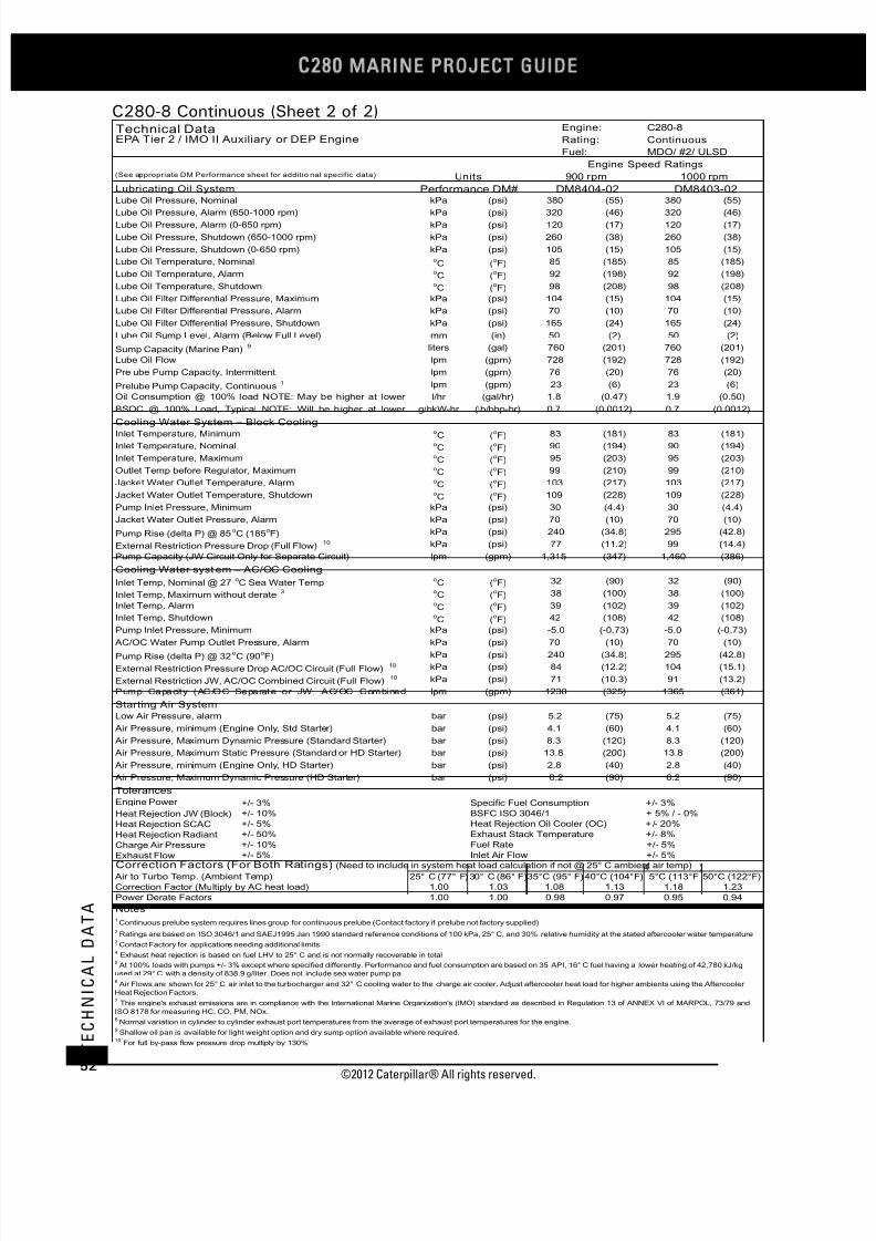
7/23/2019 1.- c280 Epa Tier 2 - Imo II Marine Project Guide
http://slidepdf.com/reader/full/1-c280-epa-tier-2-imo-ii-marine-project-guide 60/222
C28
MARINE PROJECT GUIDE
©2012 Caterpillar® All rights reserved.52
T E C H N I C A L D A T A
C280-8 Continuous (Sheet 2 of 2)
kPa (psi) (55) 380 (55)
kPa (psi) (46) 320 (46)kPa (psi) (17) 120 (17)
kPa (psi) (38) 260 (38)
kPa (psi) (15) 105 (15)oC (
oF) (185) 85 (185)
oC (
oF) (198) 92 (198)
oC (
oF) (208) 98 (208)
kPa (psi) (15) 104 (15)
kPa (psi) (10) 70 (10)
kPa (psi) (24) 165 (24)
mm (in) (2) 50 (2)
liters (gal) (201) 760 (201)
lpm (gpm) (192) 728 (192)
lpm (gpm) (20) 76 (20)
lpm (gpm) (6) 23 (6)
l/hr (gal/hr) (0.47) 1.9 (0.50)
g/bkW-hr (lb/bhp-hr) (0.0012) 0.7 (0.0012)
oC (
oF) (181) 83 (181)
oC (
oF) (194) 90 (194)
oC (
oF) (203) 95 (203)
oC (
oF) (210) 99 (210)
oC (
oF) (217) 103 (217)
oC (
oF) (228) 109 (228)
kPa (psi) (4.4) 30 (4.4)
kPa (psi) (10) 70 (10)
kPa (psi) (34.8) 295 (42.8)
kPa (psi) (11.2) 99 (14.4)
lpm (gpm) (347) 1,460 (386)
oC (
oF) (90) 32 (90)
oC (
oF) (100) 38 (100)
oC (
oF) (102) 39 (102)
oC (
oF) (108) 42 (108)
kPa (psi) (-0.73) -5.0 (-0.73)
kPa (psi) (10) 70 (10)
kPa (psi) (34.8) 295 (42.8)
kPa (psi) (12.2) 104 (15.1)
kPa (psi) (10.3) 91 (13.2)
lpm (gpm) (325) 1365 (361)
bar (psi) (75) 5.2 (75)
bar (psi) (60) 4.1 (60)
bar (psi) (120) 8.3 (120)
bar (psi) (200) 13.8 (200)
bar (psi) (40) 2.8 (40)
bar (psi) (90) 6.2 (90)
Engine Power +/- 3%
Heat Rejection JW (Block) +/- 10%
Heat Rejection SCAC +/- 5%
Heat Rejection Radiant +/- 50%
Charge Air Pressure +/- 10%
Exhaust Flow +/- 5%
25° C (77° F)30° C (86° F) 40°C (104°F) 5°C (113°F 50°C (122°F)
1.00 1.03 1.13 1.18 1.23
1.00 1.00 0.97 0.95 0.94
Outlet Temp before Regulator, Maximum 99
Inlet Temperature, Minimum 83
Inlet Temperature, Nominal 90
Inlet Temperature, Maximum 95
Prelube Pump Capacity, Intermittent 76
Prelube Pump Capacity, Continuous1
Cooling Water System – Block Cooling
23
Oil Consumption @ 100% load NOTE: May be higher at lower 1.8
BSOC @ 100% Load, Typical NOTE: Will be higher at lower 0.7
Sump Capacity (Marine Pan)9 760
Lube Oil Flow 728
Lube Oil Filter Differential Pressure, Shutdown 165
Lube Oil Sump Level, Alarm (Below Full Level) 50
Lube Oil Filter Differential Pressure, Maximum 104
Lube Oil Filter Differential Pressure, Alarm 70
Lube Oil Temperature, Alarm 92
Lube Oil Temperature, Shutdown 98
Lube Oil Pressure, Shutdown (0-650 rpm) 105
Lube Oil Temperature, Nominal 85
Lube Oil Pressure, Alarm (0-650 rpm) 120
Lube Oil Pressure, Shutdown (650-1000 rpm) 260
Lube Oil Pressure, Nominal 380
Lube Oil Pressure, Alarm (650-1000 rpm) 320
MDO/ #2/ ULSD
Engine Speed Ratings
Cooling Water syst em – AC/OC Cooling
Rating:
Fuel:
C280-8
EPA Tier 2 / IMO II Auxiliary or DEP Engine Continuous
Inlet Temp, Nominal @ 27oC Sea Water Temp 32
Inlet Temp, Maximum without derate3 38
Inlet Temp, Alarm 39
Inlet Temp, Shutdown 42
Air Pressure, Maximum Dynamic Pressure (HD Starter)
External Restriction Pressure Drop AC/OC Circuit (Full Flow)10 84
External Restriction JW, AC/OC Combined Circuit (Full Flow)10 71
Air Pressure, Maximum Static Pressure (Standard or HD Starter) 13.8
Air Pressure, minimum (Engine Only, HD Starter) 2.8
Air Pressure, minimum (Engine Only, Std Starter) 4.1
Air Pressure, Maximum Dynamic Pressure (Standard Starter) 8.3
Technical Data Engine:
1000 rpm
Lubricating Oil System Performance DM# DM8404-02 DM8403-02
(See appropriate DM Performance sheet for additio nal specific data) Units 900 rpm
Jacket Water Outlet Temperature, Alarm 103
Jacket Water Outlet Temperature, Shutdown 109
Jacket Water Outlet Pressure, Alarm 70
Pump Inlet Pressure, Minimum 30
Pump Rise (delta P) @ 85oC (185
oF) 240
External Restriction Pressure Drop (Full Flow)10 77
Pump Capacity (JW Circuit Only for Separate Circuit) 1,315
-5.0
AC/OC Water Pump Outlet Pressure, Alarm 70
Pump Rise (delta P) @ 32oC (90
oF) 240
Pump Inlet Pressure, Minimum
Specific Fuel Consumption +/- 3%
BSFC ISO 3046/1 + 5% / - 0%
1230
Starting Air System
Low Air Pressure, alarm 5.2
Pump Capacity (AC/OC Separate or JW, AC/OC Combined
6.2
Tolerances
Fuel Rate +/- 5%
Inlet Air Flow +/- 5%Correction Factors (For Both Ratings) (Need to include in system heat load calculation if not @ 25° C ambient air temp)
Heat Rejection Oil Cooler (OC) +/- 20%
Exhaust Stack Temperature +/- 8%
5 At 100% loads with pumps +/- 3% except where specified differently. Performance and fuel consumption are based on 35 API, 16° C fuel having a lower heating of 42,780 kJ/kg
used at 29° C with a density of 838.9 g/liter. Does not include sea water pump pa
Air to Turbo Temp. (Ambient Temp) 35°C (95° F)
Correction Factor (Multiply by AC heat load) 1.08
Power Derate Factors 0.98
10 For full by-pass flow pressure drop multiply by 130%
6 Air Flows are shown for 25° C air inlet to the turbocharger and 32° C cooling water to the charge air cooler. Adjust aftercooler heat load for higher ambients using the Aftercooler
Heat Rejection Factors.7 This engine's exhaust emissions are in compliance with the International Marine Organization's (IMO) standard as described in Regulation 13 of ANNEX VI of MARPOL, 73/79 and
ISO 8178 for measuring HC, CO, PM, NOx.8 Normal variation in cylinder to cylinder exhaust port temperatures from the average of exhaust port temperatures for the engine.
9 Shallow oil pan is available for light weight option and dry sump option available where required.
Notes1 Continuous prelube system requires lines group for continuous prelube (Contact factory if prelube not factory supplied)
2 Ratings are based on ISO 3046/1 and SAEJ1995 Jan 1990 standard reference conditions of 100 kPa, 25° C, and 30% relative humidity at the stated aftercooler water temperature
3 Contact Factory for applications needing additional limits
4 Exhaust heat rejection is based on fuel LHV to 25° C and is not normally recoverable in total
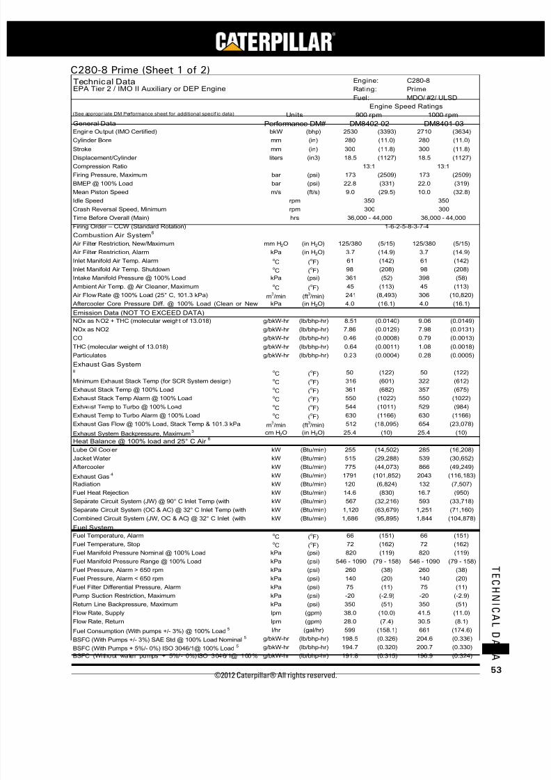
7/23/2019 1.- c280 Epa Tier 2 - Imo II Marine Project Guide
http://slidepdf.com/reader/full/1-c280-epa-tier-2-imo-ii-marine-project-guide 61/222
©2012 Caterpillar® All rights reserved. 53
T E C H N I C A L D A T A
C280-8 Prime (Sheet 1 of 2)
bkW (bhp) (3393) 2710 (3634)mm (in) (11.0) 280 (11.0)
mm (in) (11.8) 300 (11.8)
liters (in3) (1127) 18.5 (1127)
bar (psi) (2509) 173 (2509)
bar (psi) (331) 22.0 (319)
m/s (ft/s) (29.5) 10.0 (32.8)
mm H2O (in H2O) (5/15) 125/380 (5/15)
kPa (in H2O) (14.9) 3.7 (14.9)oC (
oF) (142) 61 (142)
oC (oF) (208) 98 (208)
kPa (psi) (52) 398 (58)oC (
oF) (113) 45 (113)
m3/min (ft
3/min) (8,493) 306 (10,820)
kPa (in H2O) (16.1) 4.0 (16.1)
g/bkW-hr (lb/bhp-hr) (0.0140) 9.06 (0.0149)
g/bkW-hr (lb/bhp-hr) (0.0129) 7.98 (0.0131)
g/bkW-hr (lb/bhp-hr) (0.0008) 0.79 (0.0013)
g/bkW-hr (lb/bhp-hr) (0.0011) 1.08 (0.0018)
g/bkW-hr (lb/bhp-hr) (0.0004) 0.28 (0.0005)
oC (
oF) (122) 50 (122)
oC (
oF) (601) 322 (612)
oC (
oF) (682) 357 (675)
oC (
oF) (1022) 550 (1022)
oC (
oF) (1011) 529 (984)
oC (
oF) (1166) 630 (1166)
m3/min (ft
3/min) (18,095) 654 (23,078)
cm H2O (in H2O) (10) 25.4 (10)
kW (Btu/min) (14,502) 285 (16,208)
kW (Btu/min) (29,288) 539 (30,652)
kW (Btu/min) (44,073) 866 (49,249)
kW (Btu/min) (101,852) 2043 (116,183)
kW (Btu/min) (6,824) 132 (7,507)
kW (Btu/min) (830) 16.7 (950)
kW (Btu/min) (32,216) 593 (33,718)
kW (Btu/min) (63,679) 1,251 (71,160)
kW (Btu/min) (95,895) 1,844 (104,878)
o
C (o
F) (151) 66 (151)oC (
oF) (162) 72 (162)
kPa (psi) (119) 820 (119)
kPa (psi) (79 - 158) 546 - 1090 (79 - 158)
kPa (psi) (38) 260 (38)
kPa (psi) (20) 140 (20)
kPa (psi) (11) 75 (11)
kPa (psi) (-2.9) -20 (-2.9)
kPa (psi) (51) 350 (51)
lpm (gpm) (10.0) 41.5 (11.0)
lpm (gpm) (7.4) 30.5 (8.1)
l/hr (gal/hr) (158.1) 661 (174.6)
g/bkW-hr (lb/bhp-hr) (0.326) 204.6 (0.336)
g/bkW-hr (lb/bhp-hr) (0.320) 200.7 (0.330)
g/bkW-hr (lb/bhp-hr) (0.315) 196.9 (0.324)
Minimum Exhaust Stack Temp (for SCR System design) 316
Fuel Manifold Pressure Nominal @ 100% Load 820
BSFC (Without water pumps + 5%/- 0%)ISO 3046/1@ 100%
191.8
BSFC (With Pumps + 5%/- 0%) ISO 3046/1@ 100% Load5 194.7
-20
350
Flow Rate, Return 28.0
Fuel Consumption (With pumps +/- 3%) @ 100% Load5 599
BSFC (With Pumps +/- 3%) SAE Std @ 100% Load Nominal5
14.6
Radiation
198.5
Fuel Temperature, Stop 72
Flow Rate, Supply 38.0
Fuel Manifold Pressure Range @ 100% Load 546 - 1090
Fuel Filter Differential Pressure, Alarm
Lube Oil Cooler 255
Pump Suction Restriction, Maximum
Fuel Pressure, Alarm > 650 rpm 260
Fuel Pressure, Alarm < 650 rpm 140
Exhaust Gas4 1791
Fuel Heat Rejection
Exhaust Gas System 8 50
Exhaust Stack Temp @ 100% Load 361
120
Jacket Water 515
Aftercooler 775
Air Filter Restriction, Alarm 3.7
NOx as NO2 + THC (molecular weight of 13.018) 8.51
Inlet Manifold Air Temp. Shutdown
Heat Balance @ 100% load and 25° C Air6
THC (molecular weight of 13.018) 0.64
Particulates 0.23
36,000 - 44,000
1-6-2-5-8-3-7-4
hrs
98
Combustion Air System6
Ambient Air Temp. @ Air Cleaner, Maximum 45
Firing Order – CCW (Standard Rotation)
Intake Manifold Pressure @ 100% Load 361
Separate Circuit System (OC & AC) @ 32° C Inlet Temp (with 1,120
Combined Circuit System (JW, OC & AC) @ 32° C Inlet (with
125/380
Time Before Overall (Main) 36,000 - 44,000
Inlet Manifold Air Temp. Alarm 61
Air Filter Restriction, New/Maximum
CO
Air Flow Rate @ 100% Load (25° C, 101.3 kPa) 241
Emission Data (NOT TO EXCEED DATA)
Aftercooler Core Pressure Diff. @ 100% Load (Clean or New
Separate Circuit System (JW) @ 90° C Inlet Temp (with 567
0.46
NOx as NO2 7.86
4.0
Idle Speed 350 350
Crash Reversal Speed, Minimum 300 300
rpm
rpm
BMEP @ 100% Load 22.8
Mean Piston Speed 9.0
13:1 13:1
Firing Pressure, Maximum 173
Compression Ratio
Stroke 300
Displacement/Cylinder 18.5
Engine Output (IMO Certified) 2530Cylinder Bore 280
General Data Performance DM# DM8402-02 DM8401-03
(See appropr iate DM Performance sheet for additional specif ic data) Units 900 rpm 1000 rpm
Fuel: MDO/ #2/ ULSD
Engine Speed Ratings
Technical Data Engine: C280-8
EPA Tier 2 / IMO II Auxiliary or DEP Engine Rating: Prime
1,686
Fuel System
Fuel Temperature, Alarm 66
75
Return Line Backpressure, Maximum
Exhaust Stack Temp Alarm @ 100% Load 550
Exhaust Temp to Turbo @ 100% Load 544
Exhaust System Backpressure, Maximum3 25.4
Exhaust Temp to Turbo Alarm @ 100% Load 630
Exhaust Gas Flow @ 100% Load, Stack Temp & 101.3 kPa 512

7/23/2019 1.- c280 Epa Tier 2 - Imo II Marine Project Guide
http://slidepdf.com/reader/full/1-c280-epa-tier-2-imo-ii-marine-project-guide 62/222
C28
MARINE PROJECT GUIDE
©2012 Caterpillar® All rights reserved.54
T E C H N I C A L D A T A
C280-8 Prime (Sheet 2 of 2)
kPa (psi) (55) 380 (55)
kPa (psi) (46) 320 (46)kPa (psi) (17) 120 (17)
kPa (psi) (38) 260 (38)
kPa (psi) (15) 105 (15)oC (
oF) (185) 85 (185)
oC (
oF) (198) 92 (198)
oC (
oF) (208) 98 (208)
kPa (psi) (15) 104 (15)
kPa (psi) (10) 70 (10)
kPa (psi) (24) 165 (24)
mm (in) (2) 50 (2)
liters (gal) (201) 760 (201)
lpm (gpm) (192) 728 (192)
lpm (gpm) (20) 76 (20)
lpm (gpm) (6) 23 (6)
l/hr (gal/hr) (0.51) 2.1 (0.55)
g/bkW-hr (lb/bhp-hr) (0.0012) 0.7 (0.0012)
oC (
oF) (181) 83 (181)
oC (
oF) (194) 90 (194)
oC (
oF) (203) 95 (203)
oC (
oF) (210) 99 (210)
oC (
oF) (217) 103 (217)
oC (
oF) (228) 109 (228)
kPa (psi) (4.4) 30 (4.4)
kPa (psi) (10) 70 (10)
kPa (psi) (34.8) 295 (42.8)
kPa (psi) (11.2) 99 (14.4)
lpm (gpm) (347) 1,460 (386)
oC (
oF) (90) 32 (90)
oC (
oF) (100) 38 (100)
oC (
oF) (102) 39 (102)
oC (
oF) (108) 42 (108)
kPa (psi) (-0.73) -5.0 (-0.73)
kPa (psi) (10) 70 (10)
kPa (psi) (34.8) 295 (42.8)
kPa (psi) (12.2) 104 (15.1)
kPa (psi) (10.3) 91 (13.2)
lpm (gpm) (325) 1365 (361)
bar (psi) (75) 5.2 (75)
bar (psi) (60) 4.1 (60)
bar (psi) (120) 8.3 (120)
bar (psi) (200) 13.8 (200)
bar (psi) (40) 2.8 (40)
bar (psi) (90) 6.2 (90)
Engine Power +/- 3%
Heat Rejection JW (Block) +/- 10%
Heat Rejection SCAC +/- 5%
Heat Rejection Radiant +/- 50%
Charge Air Pressure +/- 10%
Exhaust Flow +/- 5%
25° C (77° F)30° C (86° F) 40°C (104°F)45°C (113°F)50°C (122°F)
1.00 1.03 1.13 1.18 1.23
1.00 1.00 0.97 0.95 0.94
9 Shallow oil pan is available for light weight option and dry sump option available where required.
DM8402-02 DM8401-03Lubricating Oil System
PrimeTechnical Data
13.8
Low Air Pressure, alarm 5.2
7 This engine's exhaust emissions are in compliance with the International Marine Organization's (IMO) standard as described in Regulation 13 of ANNEX VI of MARPOL, 73/79 and
ISO 8178 for measuring HC, CO, PM, NOx.
2 Ratings are based on ISO 3046/1 and SAEJ1995 Jan 1990 standard reference conditions of 100 kPa, 25° C, and 30% relative humidity at the stated aftercooler water temperature
3 Contact Factory for applications needing additional limits
4 Exhaust heat rejection is based on fuel LHV to 25° C and is not normally recoverable in total
At 100% loads with pumps +/- 3% except where specified differently. Performance and fuel consumption are based on 35 API, 16° C fuel having a lower heating of 42,780 kJ/kg
used at 29° C with a density of 838.9 g/liter. Does not include sea water pump pa
6 Air Flows are shown for 25° C air inlet to the turbocharger and 32° C cooling water to the charge air cooler. Adjust aftercooler heat load for higher ambients using the Aftercooler
Heat Rejection Factors.
Air Pressure, Maximum Dynamic Pressure (Standard Starter) 8.3
Air Pressure, minimum (Engine Only, HD Starter)
Correction Factor (Multiply by AC heat load) 1.08
MDO/ #2/ ULSD
Tolerances
Specific Fuel Consumption
Air Max Static Pressure Reference (Standard or HD Starter)
240
External Restriction Pressure Drop AC/OC Circuit (Full Flow)10 84
Notes1 Continuous prelube system requires lines group for continuous prelube (Contact factory if prelube not factory supplied)
Power Derate Factors 0.98
Starting Air System
Air Pressure, minimum (Engine Only, Std Starter) 4.1
External Restriction JW, AC/OC Combined Circuit (Full Flow)10 71
Inlet Temp, Alarm
Pump Capacity (AC/OC Separate or JW, AC/OC Combined 1230
Pump Inlet Pressure, Minimum -5.0
AC/OC Water Pump Outlet Pressure, Alarm 70
Pump Rise (delta P) @ 32oC (90
oF)
109
Pump Inlet Pressure, Minimum 30
39
Inlet Temp, Shutdown 42
External Restriction Pressure Drop (Full Flow)10 77
Pump Rise (delta P) @ 85oC (185
oF)
Fuel:
C280-8
Inlet Temp, Nominal @ 27oC Sea Water Temp 32
Jacket Water Outlet Temperature, Alarm 103
Jacket Water Outlet Temperature, Shutdown
95
Outlet Temp before Regulator, Maximum 99
Inlet Temp, Maximum without derate3 38
Cooling Water system – AC/OC Cooling
Jacket Water Outlet Pressure, Alarm 70
Pump Capacity (JW Circuit Only for Separate Circuit) 1,315
Lube Oil Filter Differential Pressure, Shutdown 165
Lube Oil Filter Differential Pressure, Alarm 70
240
Inlet Temperature, Minimum 83
Inlet Temperature, Nominal 90
Inlet Temperature, Maximum
Lube Oil Flow 728
760
92
Lube Oil Temperature, Shutdown 98
Lube Oil Sump Level, Alarm (Below Full Level) 50
Lube Oil Filter Differential Pressure, Maximum 104
Cooling Water System – Block Cooli ng
BSOC @ 100% Load, Typical NOTE: Will be higher at lower 0.7
Prelube Pump Capacity, Continuous1 23
Oil Consumption @ 100% load NOTE: May be higher at lower 1.9
Prelube Pump Capacity, Intermittent
Lube Oil Pressure, Shutdown (650-1000 rpm) 260
Lube Oil Temperature, Nominal 85
Lube Oil Pressure, Shutdown (0-650 rpm) 105
Lube Oil Temperature, Alarm
Sump Capacity (Marine Pan)9
76
Lube Oil Pressure, Alarm (650-1000 rpm) 320Lube Oil Pressure, Alarm (0-650 rpm) 120
EPA Tier 2 / IMO II Auxi liary or DEP Engine Rating:
Engine Speed Ratings
Units 900 rpm 1000 rpm
Engine:
Lube Oil Pressure, Nominal 380
(See appropriate DM Performance sheet for additional specific data)
10 For full by-pass flow pressure drop multiply by 130%
8 Normal variation in cylinder to cylinder exhaust port temperatures from the average of exhaust port temperatures for the engine.
BSFC ISO 3046/1 + 5% / - 0%
Exhaust Stack Temperature +/- 8%
Air Pressure, Maximum Dynamic Pressure (HD Starter) 6.2
2.8
Performance DM#
Correction Factors (For Both Ratings) (Need to include in system heat load calculation if not @ 25° C ambient air temp)
Air to Turbo Temp. (Ambient Temp) 35°C (95° F)
+/- 3%
Heat Rejection Oil Cooler (OC) +/- 20%
Fuel Rate +/- 5%
Inlet Air Flow +/- 5%

7/23/2019 1.- c280 Epa Tier 2 - Imo II Marine Project Guide
http://slidepdf.com/reader/full/1-c280-epa-tier-2-imo-ii-marine-project-guide 63/222
©2012 Caterpillar® All rights reserved. 55
T E C H N I C A L D A T A
C280-12 Continuous (Sheet 1 of 2)
bkW (bhp) (4640) 3700 (4962)mm (in) (11.0) 280 (11.0)
mm (in) (11.8) 300 (11.8)
liters (in3) (1127) 18.5 (1127)
bar (psi) (2350) 162 (2350)
bar (psi) (302) 20.0 (291)
m/s (ft/s) (29.5) 10.0 (32.8)
mm H2O (in H2O) (5/15) 125/380 (5/15)
kPa (in H2O) (14.9) 3.7 (14.9)oC (
oF) (142) 61 (142)
oC (oF) (208) 98 (208)
kPa (psi) (51) 329 (48)oC (
oF) (113) 45 (113)
m3/min (ft
3/min) (12,448) 386 (13,631)
kPa (in H2O) (16.1) 4.0 (16.1)
g/bkW-hr (lb/bhp-hr) (0.0173) 10.93 (0.0180)
g/bkW-hr (lb/bhp-hr) (0.0160) 10.02 (0.0165)
g/bkW-hr (lb/bhp-hr) (0.0014) 0.75 (0.0012)
g/bkW-hr (lb/bhp-hr) (0.0013) 0.91 (0.0015)
g/bkW-hr (lb/bhp-hr) (0.0004) 0.23 (0.0004)
oC (
oF) (122) 50 (122)
oC (
oF) (613) 278 (532)
oC (
oF) (714) 374 (704)
o
C (
o
F) (1022) 550 (1022)oC (
oF) (1022) 518 (964)
oC (
oF) (1166) 630 (1166)
m3/min (ft
3/min) (26,136) 821 (28,986)
cm H2O (in H2O) (10) 25.4 (10)
kW (Btu/min) (20,757) 378 (21,496)
kW (Btu/min) (41,514) 760 (43,220)
kW (Btu/min) (66,309) 1155 (65,684)
kW (Btu/min) (147,461) 2911 (165,546)
kW (Btu/min) (9,668) 182 (10,350)
kW (Btu/min) (1,251) 25.0 (1,422)
kW (Btu/min) (45,666) 836 (47,542)
kW (Btu/min) (94,533) 1,666 (94,764)
kW (Btu/min) (140,199) 2,502 (142,306)
oC (oF) (151) 66 (151)oC (
oF) (162) 72 (162)
kPa (psi) (119) 820 (119)
kPa (psi) (79 - 158) 546 - 1090 (79 - 158)
kPa (psi) (38) 260 (38)
kPa (psi) (20) 140 (20)
kPa (psi) (11) 75 (11)
kPa (psi) (-2.9) -20 (-2.9)
kPa (psi) (51) 350 (51)
lpm (gpm) (19.0) 78.5 (20.7)
lpm (gpm) (15.3) 63.4 (16.7)
l/hr (gal/hr) (223.9) 909 (240.0)
g/bkW-hr (lb/bhp-hr) (0.338) 206.0 (0.339)
g/bkW-hr (lb/bhp-hr) (0.331) 202.1 (0.332)
g/bkW-hr (lb/bhp-hr) (0.328) 199.3 (0.328)
Technical Data Engine: C280-12
EPA Tier 2 / IMO II Auxiliary or DEP Engine Rating: Continuous
Fuel: MDO/ #2/ ULSD
Engine Speed Ratings(See appropr iate DM Performance sheet fo r addition al specific data) Units 900 rpm 1000 rpm
General Data Performance DM# DM8412-02 DM8411-03
Engine Output (IMO Certified) 3460Cylinder Bore 280
Stroke 300
Displacement/Cylinder 18.5
Compression Ratio 13:1 13:1
Firing Pressure, Maximum 162
BMEP @ 100% Load 20.8
Mean Piston Speed 9.0
Idle Speed rpm 350 350
Crash Reversal Speed, Minimum rpm 300 300
Time Before Overall (Main) hrs 36,000 - 44,000 36,000 - 44,000
Firing Order – CCW (Standard Rotation) 1-12-9-4-5-8-11-2-3-10-7-6
Combustion Air System6
Air Filter Restriction, New/Maximum 125/380
Air Filter Restriction, Alarm 3.7
Inlet Manifold Air Temp. Alarm 61
Inlet Manifold Air Temp. Shutdown 98
Intake Manifold Pressure @ 100% Load 348
Ambient Air Temp. @ Air Cleaner, Maximum 45
Air Flow Rate @ 100% Load (25° C, 101.3 kPa) 353
Aftercooler Core Pressure Diff. @ 100% Load (Clean or New 4.0
Emission Data (NOT TO EXCEED DATA)
NOx as NO2 + THC (molecular weight of 13.018) 10.50
NOx as NO2 9.72
CO 0.84
THC (molecular weight of 13.018) 0.78
Particulates 0.26
Exhaust Gas System
Exhaust Cyl Port Deviation Alarm (From Average) @ 100% Load 50
Minimum Exhaust Stack Temp (for SCR System design) 323
Exhaust Stack Temp @ 100% Load 379
Exhaust Stack Temp Alarm @ 100% Load 550Exhaust Temp to Turbo @ 100% Load 550
Exhaust Temp to Turbo Alarm @ 100% Load 630
Exhaust Gas Flow @ 100% Load, Stack Temp & 101.3 kPa 740
Exhaust System Backpressure, Maximum3 25.4
Heat Balance @ 100% load and 25° C Air6
Lube Oil Cooler 365
Jacket Water 730
Aftercooler 1166
Exhaust Gas4 2593
Radiation 170
Fuel Heat Rejection 22.0
Separate Circuit System (JW) @ 90° C Inlet Temp (with 803
Separate Circuit System (OC & AC) @ 32° C Inlet Temp (with 1,662
Combined Circuit System (JW, OC & AC) @ 32° C Inlet (with 2,465
Fuel System
Fuel Temperature, Alarm 66
Fuel Temperature, Stop 72
Fuel Manifold Pressure Nominal @ 100% Load 820
Fuel Manifold Pressure Range @ 100% Load 546 - 1090
Fuel Pressure, Alarm > 650 rpm 260
Fuel Pressure, Alarm < 650 rpm 140
Fuel Filter Differential Pressure, Alarm 75
Pump Suction Restriction, Maximum -20
Return Line Backpressure, Maximum 350
Flow Rate, Supply 72.0
Flow Rate, Return 57.9
Fuel Consumption (With pumps +/- 3%) @ 100% Load5 848
BSFC (With Pumps +/- 3%) SAE Std @ 100% Load Nominal5 205.5
BSFC (With Pumps + 5%/- 0%) ISO 3046/1@ 100% Load5 201.6
BSFC (Without water pumps + 5%/- 0%)ISO 3046/1@ 100%
199.4

7/23/2019 1.- c280 Epa Tier 2 - Imo II Marine Project Guide
http://slidepdf.com/reader/full/1-c280-epa-tier-2-imo-ii-marine-project-guide 64/222
C28
MARINE PROJECT GUIDE
©2012 Caterpillar® All rights reserved.56
T E C H N I C A L D A T A
C280-12 Continuous (Sheet 2 of 2)
kPa (psi) (55) 380 (55)
kPa (psi) (46) 320 (46)kPa (psi) (17) 120 (17)
kPa (psi) (38) 260 (38)
kPa (psi) (15) 105 (15)oC (
oF) (185) 85 (185)
oC (
oF) (198) 92 (198)
oC (
oF) (208) 98 (208)
kPa (psi) (15) 104 (15)
kPa (psi) (10) 70 (10)
kPa (psi) (24) 165 (24)
mm (in) (2) 50 (2)
liters (gal) (240) 910 (240)
lpm (gpm) (229) 868 (229)
lpm (gpm) (20) 76 (20)
lpm (gpm) (6) 23 (6)
l/hr (gal/hr) (0.70) 2.8 (0.75)
g/bkW-hr (lb/bhp-hr) (0.0012) 0.7 (0.0012)
oC (
oF) (181) 83 (181)
oC (
oF) (194) 90 (194)
oC (
oF) (203) 95 (203)
oC (
oF) (210) 99 (210)
oC (
oF) (217) 103 (217)
oC (
oF) (228) 109 (228)
kPa (psi) (4.4) 30 (4.4)
kPa (psi) (10) 70 (10)
kPa (psi) (34.8) 295 (42.8)
kPa (psi) (11.7) 103 (14.9)
lpm (gpm) (695) 2,920 (771)
oC (
oF) (90) 32 (90)
oC (
oF) (100) 38 (100)
oC (
oF) (102) 39 (102)
oC (
oF) (108) 42 (108)
kPa (psi) (-0.73) -5.0 (-0.73)
kPa (psi) (10) 70 (10)
kPa (psi) (35.5) 305 (44.2)
kPa (psi) (9.6) 85 (12.3)
kPa (psi) (9.6) 85 (12.3)
lpm (gpm) (412) 1730 (457)
bar (psi) (75) 5.2 (75)
bar (psi) (60) 4.1 (60)
bar (psi) (150) 10.4 (150)
bar (psi) (200) 13.8 (200)
bar (psi) (40) 2.8 (40)
bar (psi) (150) 10.4 (150)
Engine Power +/- 3%
Heat Rejection JW (Block) +/- 10%
Heat Rejection SCAC +/- 5%
Heat Rejection Radiant +/- 50%
Charge Air Pressure +/- 10%
Exhaust Flow +/- 5%
25° C (77° F)30° C (86° F) 40°C (104°F) 5°C (113°F)50°C (122°F)
1.00 1.03 1.13 1.18 1.23
1.00 1.00 0.97 0.95 0.94
Technical Data Engine: C280-12
EPA Tier 2 / IMO II Auxil iary or DEP Engine Rating: Continuous
Fuel: MDO/ #2/ ULSD
Engine Speed Ratings(See appropriate DM Performance sheet for additional specific data) Units 900 rpm 1000 rpm
Lubricating Oil System Performance DM# DM8412-02 DM8411-03Lube Oil Pressure, Nominal 380
Lube Oil Pressure, Alarm (650-1000 rpm) 320Lube Oil Pressure, Alarm (0-650 rpm) 120
Lube Oil Pressure, Shutdown (650-1000 rpm) 260
Lube Oil Pressure, Shutdown (0-650 rpm) 105
Lube Oil Temperature, Nominal 85
Lube Oil Temperature, Alarm 92
Lube Oil Temperature, Shutdown 98
Lube Oil Filter Differential Pressure, Maximum 104
Lube Oil Filter Differential Pressure, Alarm 70
Lube Oil Filter Differential Pressure, Shutdown 165
Lube Oil Sump Level, Alarm (Below Full Level) 50
Sump Capacity (Marine Pan)9 910
Lube Oil Flow 868
Prelube Pump Capacity, Intermittent 76
Prelube Pump Capacity, Continuous1 23
Oil Consumption @ 100% load NOTE: May be higher at lower 2.7
BSOC @ 100% Load, Typical NOTE: Will be higher at lower 0.7
Cooling Water System – Block CoolingInlet Temperature, Minimum 83
Inlet Temperature, Nominal 90
Inlet Temperature, Maximum 95
Outlet Temp before Regulator, Maximum 99
Jacket Water Outlet Temperature, Alarm 103
Jacket Water Outlet Temperature, Shutdown 109
Pump Inlet Pressure, Minimum 30
Jacket Water Outlet Pressure, Alarm 70
Pump Rise (delta P) @ 85oC (185
oF) 240
External Restriction Pressure Drop (Full Flow)10 81
Pump Capacity (JW Circuit Only for Separate Circuit) 2,630
Cooling Water syst em – AC/OC Cooling
Inlet Temp, Nominal @ 27oC Sea Water Temp 32
Inlet Temp, Maximum without derate3 38
Inlet Temp, Alarm 39
Inlet Temp, Shutdown 42
Pump Inlet Pressure, Minimum -5.0
AC/OC Water Pump Outlet Pressure, Alarm 70
Pump Rise (delta P) @ 32oC (90
oF) 245
External Restriction Pressure Drop AC/OC Circuit (Full Flow)10 66
External Restriction JW, AC/OC Combined Circuit (Full Flow)10 66
Pump Capacity (AC/OC Separate or JW, AC/OC Combined 1560
Starting Air System
Low Air Pressure, alarm 5.2
Air Pressure, minimum (Engine Only, Std Starter) 4.1
Air Pressure, Maximum Dynamic Pressure (Standard Starter) 10.4
Air Pressure, Maximum Static Pressure (Standard or Dual 13.8
Air Pressure, minimum (Engine Only, Dual Starter) 2.8
Air Pressure, Maximum Dynamic Pressure (Dual Starter) 10.4
Tolerances
Specific Fuel Consumption +/- 3%
BSFC ISO 3046/1 + 5% / - 0%
Heat Rejection Oil Cooler (OC) +/- 20%
Exhaust Stack Temperature +/- 8%
Fuel Rate +/- 5%
Inlet Air Flow +/- 5%
Correction Factors (For Both Ratings) (Need to include in system heat load calculation if not @ 25° C ambient air temp)
Air to Turbo Temp. (Ambient Temp) 35°C (95° F)
Correction Factor (Multiply by AC heat load) 1.08
Power Derate Factors 0.98
Notes1 Continuous prelube system requires lines group for continuous prelube (Contact factory if prelube not factory supplied)
2 Ratings are based on ISO 3046/1 and SAEJ1995 Jan 1990 standard reference conditions of 100 kPa, 25° C, and 30% relative humidity at the stated aftercooler water temperature
3 Contact Factory for applications needing additional limits
8 Normal variation in cylinder to cylinder exhaust port temperatures from the average of exhaust port temperatures for the engine.
9 Shallow oil pan is available for light weight option and dry sump option available where required.10
For full by-pass flow pressure drop multiply by 130%
4 Exhaust heat rejection is based on fuel LHV to 25° C and is not normally recoverable in total5 At 100% loads with pumps +/- 3% except where specified differently. Performance and fuel consumption are based on 35 API, 16° C fuel having a lower heating of 42,780 kJ/kg
used at 29° C with a density of 838.9 g/liter. Does not include sea water pump pa6 Air Flows are shown for 25° C air inlet to the turbocharger and 32° C cooling water to the charge air cooler. Adjust aftercooler heat load for higher ambients using the Aftercooler
Heat Rejection Factors.7 This engine's exhaust emissions are in compliance with the International Marine Organization's (IMO) standard as described in Regulation 13 of ANNEX VI of MARPOL, 73/79 and
ISO 8178 for measuring HC, CO, PM, NOx.

7/23/2019 1.- c280 Epa Tier 2 - Imo II Marine Project Guide
http://slidepdf.com/reader/full/1-c280-epa-tier-2-imo-ii-marine-project-guide 65/222
©2012 Caterpillar® All rights reserved. 57
T E C H N I C A L D A T A
C280-12 Prime (Sheet 1 of 2)
bkW (bhp) (5096) 4060 (5445)mm (in) (11.0) 280 (11.0)
mm (in) (11.8) 300 (11.8)
liters (in3) (1127) 18.5 (1127)
bar (psi) (2509) 173 (2509)
bar (psi) (332) 22.0 (319)
m/s (ft/s) (29.5) 10.0 (32.8)
mm H2O (in H2O) (5/15) 125/380 (5/15)
kPa (in H2O) (14.9) 3.7 (14.9)oC (
oF) (142) 61 (142)
oC (oF) (208) 98 (208)
kPa (psi) (52) 349 (51)oC (
oF) (113) 45 (113)
m3/min (ft
3/min) (12,840) 409 (14,458)
kPa (in H2O) (16.1) 4.0 (16.1)
g/bkW-hr (lb/bhp-hr) (0.0177) 10.22 (0.0168)
g/bkW-hr (lb/bhp-hr) (0.0163) 9.30 (0.0153)
g/bkW-hr (lb/bhp-hr) (0.0016) 0.66 (0.0011)
g/bkW-hr (lb/bhp-hr) (0.0013) 0.92 (0.0015)
g/bkW-hr (lb/bhp-hr) (0.0005) 0.21 (0.0003)
oC (
oF) (122) 50 (122)
oC (
oF) (613) 278 (532)
oC (
oF) (706) 377 (710)
oC (
oF) (1022) 550 (1022)
oC (
oF) (1013) 540 (1004)
oC (
oF) (1166) 630 (1166)
m3/min (ft
3/min) (26,334) 876 (30,943)
cm H2O (in H2O) (10) 25.4 (10)
kW (Btu/min) (21,838) 398 (22,634)
kW (Btu/min) (44,017) 806 (45,836)
kW (Btu/min) (71,143) 1312 (74,612)
kW (Btu/min) (157,015) 3142 (178,682)
kW (Btu/min) (10,464) 199 (11,317)
kW (Btu/min) (1,251) 25.0 (1,422)
kW (Btu/min) (48,418) 887 (50,420)
kW (Btu/min) (100,906) 1,855 (105,503)
kW (Btu/min) (149,324) 2,742 (155,923)
o
C (o
F) (151) 66 (151)oC (
oF) (162) 72 (162)
kPa (psi) (119) 820 (119)
kPa (psi) (79 - 158) 546 - 1090 (79 - 158)
kPa (psi) (38) 260 (38)
kPa (psi) (20) 140 (20)
kPa (psi) (11) 75 (11)
kPa (psi) (-2.9) -20 (-2.9)
kPa (psi) (51) 350 (51)
lpm (gpm) (19.0) 78.5 (20.7)
lpm (gpm) (15.0) 62.0 (16.4)
l/hr (gal/hr) (241.6) 992 (262.0)
g/bkW-hr (lb/bhp-hr) (0.332) 204.9 (0.337)
g/bkW-hr (lb/bhp-hr) (0.326) 201.0 (0.330)
g/bkW-hr (lb/bhp-hr) (0.322) 198.5 (0.326)
Technical Data Engine: C280-12
EPA Tier 2 / IMO II Auxil iary or DEP Engine Rating: Prime
Fuel: MDO/ #2/ ULSD
Engine Speed Ratings(See appropriate DM Performance sheet for additional specific data) Units 900 rpm 1000 rpm
General Data Performance DM# DM8410-02 DM8409-03
Engine Output (IMO Certified) 3800Cylinder Bore 280
Stroke 300
Displacement/Cylinder 18.5
Compression Ratio 13:1 13:1
Firing Pressure, Maximum 173
BMEP @ 100% Load 22.9
Mean Piston Speed 9.0
Idle Speed rpm 350 350
Crash Reversal Speed, Minimum rpm 300 300
Time Before Overall (Main) hrs 36,000 - 44,000 36,000 - 44,000
Firing Order – CCW (Standard Rotation) 1-12-9-4-5-8-11-2-3-10-7-6
Combustion Air System6
Air Filter Restriction, New/Maximum 125/380
Air Filter Restriction, Alarm 3.7
Inlet Manifold Air Temp. Alarm 61
Inlet Manifold Air Temp. Shutdown 98
Intake Manifold Pressure @ 100% Load 356
Ambient Air Temp. @ Air Cleaner, Maximum 45
Air Flow Rate @ 100% Load (25° C, 101.3 kPa) 364
Aftercooler Core Pressure Diff. @ 100% Load (Clean or New 4.0
Emission Data (NOT TO EXCEED DATA)
NOx as NO2 + THC (molecular weight of 13.018) 10.75
NOx as NO2 9.93
CO 0.96
THC (molecular weight of 13.018) 0.82
Particulates 0.28
Exhaust Gas System 8 50
Minimum Exhaust Stack Temp (for SCR System design) 323
Exhaust Stack Temp @ 100% Load 374
Exhaust Stack Temp Alarm @ 100% Load 550
Exhaust Temp to Turbo @ 100% Load 545
Exhaust Temp to Turbo Alarm @ 100% Load 630
Exhaust Gas Flow @ 100% Load, Stack Temp & 101.3 kPa 746
Exhaust System Backpressure, Maximum3 25.4
Heat Balance @ 100% load and 25° C Air6
Lube Oil Cooler 384
Jacket Water 774
Aftercooler 1251
Exhaust Gas4 2761
Radiation 184
Fuel Heat Rejection 22.0
Separate Circuit System (JW) @ 90° C Inlet Temp (with 851
Separate Circuit System (OC & AC) @ 32° C Inlet Temp (with 1,774
Combined Circuit System (JW, OC & AC) @ 32° C Inlet (with 2,626
Fuel System
Fuel Temperature, Alarm 66Fuel Temperature, Stop 72
Fuel Manifold Pressure Nominal @ 100% Load 820
Fuel Manifold Pressure Range @ 100% Load 546 - 1090
Fuel Pressure, Alarm > 650 rpm 260
Fuel Pressure, Alarm < 650 rpm 140
Fuel Filter Differential Pressure, Alarm 75
Pump Suction Restriction, Maximum -20
Return Line Backpressure, Maximum 350
Flow Rate, Supply 72.0
Flow Rate, Return 56.8
Fuel Consumption (With pumps +/- 3%) @ 100% Load5 915
BSFC (With Pumps +/- 3%) SAE Std @ 100% Load Nominal5 201.9
BSFC (With Pumps + 5%/- 0%) ISO 3046/1@ 100% Load5 198.1
BSFC (Without water pumps + 5%/- 0%)ISO 3046/1@ 100%
196.1
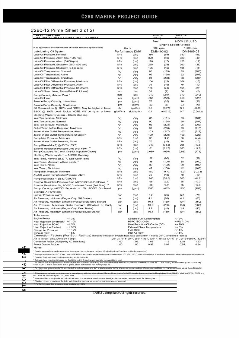
7/23/2019 1.- c280 Epa Tier 2 - Imo II Marine Project Guide
http://slidepdf.com/reader/full/1-c280-epa-tier-2-imo-ii-marine-project-guide 66/222
C28
MARINE PROJECT GUIDE
©2012 Caterpillar® All rights reserved.58
T E C H N I C A L D A T A
C280-12 Prime (Sheet 2 of 2)
kPa (psi) (55) 380 (55)
kPa (psi) (46) 320 (46)kPa (psi) (17) 120 (17)
kPa (psi) (38) 260 (38)
kPa (psi) (15) 105 (15)oC (
oF) (185) 85 (185)
oC (
oF) (198) 92 (198)
oC (
oF) (208) 98 (208)
kPa (psi) (15) 104 (15)
kPa (psi) (10) 70 (10)
kPa (psi) (24) 165 (24)
mm (in) (2) 50 (2)
liters (gal) (240) 910 (240)
lpm (gpm) (229) 868 (229)
lpm (gpm) (20) 76 (20)
lpm (gpm) (6) 23 (6)
l/hr (gal/hr) (0.77) 3.1 (0.83)
g/bkW-hr (lb/bhp-hr) (0.0012) 0.7 (0.0012)
oC (
oF) (181) 83 (181)
oC (
oF) (194) 90 (194)
oC (
oF) (203) 95 (203)
oC (
oF) (210) 99 (210)
oC (
oF) (217) 103 (217)
oC (
oF) (228) 109 (228)
kPa (psi) (4.4) 30 (4.4)
kPa (psi) (10) 70 (10)
kPa (psi) (34.8) 295 (42.8)
kPa (psi) (11.7) 103 (14.9)
lpm (gpm) (695) 2,920 (771)
oC (
oF) (90) 32 (90)
oC (
oF) (100) 38 (100)
oC (
oF) (102) 39 (102)
oC (
oF) (108) 42 (108)
kPa (psi) (-0.73) -5.0 (-0.73)
kPa (psi) (10) 70 (10)
kPa (psi) (35.5) 305 (44.2)
kPa (psi) (9.6) 85 (12.3)
kPa (psi) (9.6) 85 (12.3)
lpm (gpm) (412) 1730 (457)
bar (psi) (75) 5.2 (75)
bar (psi) (60) 4.1 (60)
bar (psi) (150) 10.4 (150)
bar (psi) (200) 13.8 (200)
bar (psi) (40) 2.8 (40)
bar (psi) (150) 10.4 (150)
Engine Power +/- 3%
Heat Rejection JW (Block) +/- 10%
Heat Rejection SCAC +/- 5%
Heat Rejection Radiant +/- 50%
Charge Air Pressure +/- 10%
Exhaust Flow +/- 5%
25° C (77° F)30° C (86° F) 40°C (104°F) 5°C (113°F)50°C (122°F)
1.00 1.03 1.13 1.18 1.23
1.00 1.00 0.97 0.95 0.94
Technical Data Engine: C280-12
EPA Tier 2 / IMO II Auxiliary or DEP Engine Rating: Prime
Fuel: MDO/ #2/ ULSD
Engine Speed Ratings(See appropriate DM Performance sheet for additional specific data) Units 900 rpm 1000 rpm
Lubricating Oil System Performance DM# DM8410-02 DM8409-03Lube Oil Pressure, Nominal 380
Lube Oil Pressure, Alarm (650-1000 rpm) 320Lube Oil Pressure, Alarm (0-650 rpm) 120
Lube Oil Pressure, Shutdown (650-1000 rpm) 260
Lube Oil Pressure, Shutdown (0-650 rpm) 105
Lube Oil Temperature, Nominal 85
Lube Oil Temperature, Alarm 92
Lube Oil Temperature, Shutdown 98
Lube Oil Filter Differential Pressure, Maximum 104
Lube Oil Filter Differential Pressure, Alarm 70
Lube Oil Filter Differential Pressure, Shutdown 165
Lube Oil Sump Level, Alarm (Below Full Level) 50
Sump Capacity (Marine Pan)9 910
Lube Oil Flow 868
Prelube Pump Capacity, Intermittent 76
Prelube Pump Capacity, Continuous1 23
Oil Consumption @ 100% load NOTE: May be higher at lower 2.9
BSOC @ 100% Load, Typical NOTE: Will be higher at lower 0.7
Cooling Water System – Block CoolingInlet Temperature, Minimum 83
Inlet Temperature, Nominal 90
Inlet Temperature, Maximum 95
Outlet Temp before Regulator, Maximum 99
Jacket Water Outlet Temperature, Alarm 103
Jacket Water Outlet Temperature, Shutdown 109
Pump Inlet Pressure, Minimum 30
Jacket Water Outlet Pressure, Alarm 70
Pump Rise (delta P) @ 85oC (185
oF) 240
External Restriction Pressure Drop (Full Flow)10 81
Pump Capacity (JW Circuit Only for Separate Circuit) 2,630
Cooling Water system – AC/OC Cooling
Inlet Temp, Nominal @ 27oC Sea Water Temp 32
Inlet Temp, Maximum without derate3 38
Inlet Temp, Alarm 39
Inlet Temp, Shutdown 42
Pump Inlet Pressure, Minimum -5.0
AC/OC Water Pump Outlet Pressure, Alarm 70
Pump Rise (delta P) @ 32oC (90
oF) 245
External Restriction Pressure Drop AC/OC Circuit (Full Flow)10 66
External Restriction JW, AC/OC Combined Circuit (Full Flow)10 66
Pump Capacity (AC/OC Separate or JW, AC/OC Combined 1560
Starting Air System
Low Air Pressure, alarm 5.2
Air Pressure, minimum (Engine Only, Std Starter) 4.1
Air Pressure, Maximum Dynamic Pressure (Standard Starter) 10.4
Air Pressure, Maximum Static Pressure (Standard or Dual 13.8
Air Pressure, minimum (Engine Only, Dual Starter) 2.8
Air Pressure, Maximum Dynamic Pressure (Dual Starter) 10.4
Tolerances
Specific Fuel Consumption +/- 3%
BSFC ISO 3046/1 + 5% / - 0%
Heat Rejection Oil Cooler (OC) +/- 20%
Exhaust Stack Temperature +/- 8%Fuel Rate +/- 5%
Inlet Air Flow +/- 5%Correction Factors (For Both Ratings) (Need to include in system heat load calculation if not @ 25° C ambient air temp)
Air to Turbo Temp. (Ambient Temp) 35°C (95° F)
Correction Factor (Multiply by AC heat load) 1.08
Power Derate Factors 0.98
Notes1 Continuous prelube system requires lines group for continuous prelube (Contact factory if prelube not factory supplied)
2 Ratings are based on ISO 3046/1 and SAEJ1995 Jan 1990 standard reference conditions of 100 kPa, 25° C, and 30% relative humidity at the stated aftercooler water temperature
3 Contact Factory for applications needing additional limits
8 Normal variation in cylinder to cylinder exhaust port temperatures from the average of exhaust port temperatures for the engine.
9 Shallow oil pan is available for light weight option and dry sump option available where required.
10 For full by-pass flow pressure drop multiply by 130%
4 Exhaust heat rejection is based on fuel LHV to 25° C and is not normally recoverable in total
At 100% loads with pumps +/- 3% except where specified differently. Performance and fuel consumption are based on 35 API, 16° C fuel having a l ower heating of 42,780 kJ/kg
used at 29° C with a density of 838.9 g/liter. Does not include sea water pump pa
6 Air Flows are shown for 25° C air inlet to the turbocharger and 32° C cooling water to the charge air cooler. Adjust aftercooler heat load for higher ambients using the Aftercooler
Heat Rejection Factors.7 This engine's exhaust emissions are in compliance with the International Marine Organization's (IMO) standard as described in Regulation 13 of ANNEX VI of MARPOL, 73/79 and
ISO 8178 for measuring HC, CO, PM, NOx.
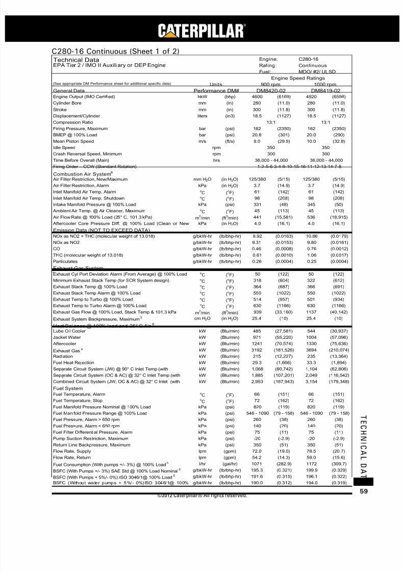
7/23/2019 1.- c280 Epa Tier 2 - Imo II Marine Project Guide
http://slidepdf.com/reader/full/1-c280-epa-tier-2-imo-ii-marine-project-guide 67/222
©2012 Caterpillar® All rights reserved. 59
T E C H N I C A L D A T A
C280-16 Continuous (Sheet 1 of 2)
bkW (bhp) (6169) 4920 (6598)mm (in) (11.0) 280 (11.0)
mm (in) (11.8) 300 (11.8)
liters (in3) (1127) 18.5 (1127)
bar (psi) (2350) 162 (2350)
bar (psi) (301) 20.0 (290)
m/s (ft/s) (29.5) 10.0 (32.8)
mm H2O (in H2O) (5/15) 125/380 (5/15)
kPa (in H2O) (14.9) 3.7 (14.9)oC (
oF) (142) 61 (142)
oC (oF) (208) 98 (208)
kPa (psi) (48) 345 (50)oC (
oF) (113) 45 (113)
m3/min (ft
3/min) (15,581) 536 (18,915)
kPa (in H2O) (16.1) 4.0 (16.1)
g/bkW-hr (lb/bhp-hr) (0.0163) 10.86 (0.0179)
g/bkW-hr (lb/bhp-hr) (0.0153) 9.80 (0.0161)
g/bkW-hr (lb/bhp-hr) (0.0008) 0.76 (0.0012)
g/bkW-hr (lb/bhp-hr) (0.0010) 1.06 (0.0017)
g/bkW-hr (lb/bhp-hr) (0.0004) 0.25 (0.0004)
oC (
oF) (122) 50 (122)
oC (
oF) (604) 322 (612)
oC (
oF) (687) 366 (691)
o
C (
o
F) (1022) 550 (1022)oC (
oF) (957) 501 (934)
oC (
oF) (1166) 630 (1166)
m3/min (ft
3/min) (33,160) 1137 (40,142)
cm H2O (in H2O) (10) 25.4 (10)
kW (Btu/min) (27,581) 544 (30,937)
kW (Btu/min) (55,220) 1004 (57,096)
kW (Btu/min) (70,574) 1330 (75,636)
kW (Btu/min) (181,526) 3694 (210,074)
kW (Btu/min) (12,227) 235 (13,364)
kW (Btu/min) (1,666) 33.3 (1,894)
kW (Btu/min) (60,742) 1,104 (62,806)
kW (Btu/min) (107,201) 2,049 (116,542)
kW (Btu/min) (167,943) 3,154 (179,348)
oC (oF) (151) 66 (151)oC (
oF) (162) 72 (162)
kPa (psi) (119) 820 (119)
kPa (psi) (79 - 158) 546 - 1090 (79 - 158)
kPa (psi) (38) 260 (38)
kPa (psi) (20) 140 (20)
kPa (psi) (11) 75 (11)
kPa (psi) (-2.9) -20 (-2.9)
kPa (psi) (51) 350 (51)
lpm (gpm) (19.0) 78.5 (20.7)
lpm (gpm) (14.3) 59.0 (15.6)
l/hr (gal/hr) (282.9) 1172 (309.7)
g/bkW-hr (lb/bhp-hr) (0.321) 199.9 (0.329)
g/bkW-hr (lb/bhp-hr) (0.315) 196.1 (0.322)
g/bkW-hr (lb/bhp-hr) (0.312) 194.0 (0.319)
Technical Data Engine: C280-16
EPA Tier 2 / IMO II Auxili ary or DEP Engine Rating: Continuous
Fuel: MDO/ #2/ ULSD
Engine Speed Ratings(See appropriate DM Performance sheet for additional specific data) Units 900 rpm 1000 rpm
General Data Performance DM# DM8420-02 DM8419-02
Engine Output (IMO Certified) 4600Cylinder Bore 280
Stroke 300
Displacement/Cylinder 18.5
Compression Ratio 13:1 13:1
Firing Pressure, Maximum 162
BMEP @ 100% Load 20.8
Mean Piston Speed 9.0
Idle Speed rpm 350 350
Crash Reversal Speed, Minimum rpm 300 300
Time Before Overall (Main) hrs 36,000 - 44,000 36,000 - 44,000
Firing Order – CCW (Standard Rotation) 1-2-5-6-3-4-9-10-15-16-11-12-13-14-7-8
Combustion Air System6
Air Filter Restriction, New/Maximum 125/380
Air Filter Restriction, Alarm 3.7
Inlet Manifold Air Temp. Alarm 61
Inlet Manifold Air Temp. Shutdown 98
Intake Manifold Pressure @ 100% Load 331
Ambient Air Temp. @ Air Cleaner, Maximum 45
Air Flow Rate @ 100% Load (25° C, 101.3 kPa) 441
Aftercooler Core Pressure Diff. @ 100% Load (Clean or New 4.0
Emission Data (NOT TO EXCEED DATA)
NOx as NO2 + THC (molecular weight of 13.018) 9.92
NOx as NO2 9.31
CO 0.46
THC (molecular weight of 13.018) 0.61
Particulates 0.26
Exhaust Gas System
Exhaust Cyl Port Deviation Alarm (From Average) @ 100% Load 50
Minimum Exhaust Stack Temp (for SCR System design) 318
Exhaust Stack Temp @ 100% Load 364
Exhaust Stack Temp Alarm @ 100% Load 550Exhaust Temp to Turbo @ 100% Load 514
Exhaust Temp to Turbo Alarm @ 100% Load 630
Exhaust Gas Flow @ 100% Load, Stack Temp & 101.3 kPa 939
Exhaust System Backpressure, Maximum3 25.4
Heat Balance @ 100% load and 25° C Air6
Lube Oil Cooler 485
Jacket Water 971
Aftercooler 1241
Exhaust Gas4 3192
Radiation 215
Fuel Heat Rejection 29.3
Separate Circuit System (JW) @ 90° C Inlet Temp (with 1,068
Separate Circuit System (OC & AC) @ 32° C Inlet Temp (with 1,885
Combined Circuit System (JW, OC & AC) @ 32° C Inlet (with 2,953
Fuel System
Fuel Temperature, Alarm 66
Fuel Temperature, Stop 72
Fuel Manifold Pressure Nominal @ 100% Load 820
Fuel Manifold Pressure Range @ 100% Load 546 - 1090
Fuel Pressure, Alarm > 650 rpm 260
Fuel Pressure, Alarm < 650 rpm 140
Fuel Filter Differential Pressure, Alarm 75
Pump Suction Restriction, Maximum -20
Return Line Backpressure, Maximum 350
Flow Rate, Supply 72.0
Flow Rate, Return 54.2
Fuel Consumption (With pumps +/- 3%) @ 100% Load5 1071
BSFC (With Pumps +/- 3%) SAE Std @ 100% Load Nominal5 195.3
BSFC (With Pumps + 5%/- 0%) ISO 3046/1@ 100% Load5 191.6
BSFC (Without water pumps + 5%/- 0%)ISO 3046/1@ 100%
190.0

7/23/2019 1.- c280 Epa Tier 2 - Imo II Marine Project Guide
http://slidepdf.com/reader/full/1-c280-epa-tier-2-imo-ii-marine-project-guide 68/222
C28
MARINE PROJECT GUIDE
©2012 Caterpillar® All rights reserved.60
T E C H N I C A L D A T A
C280-16 Continuous (Sheet 2 of 2)
kPa (psi) (55) 380 (55)
kPa (psi) (46) 320 (46)
kPa (psi) (17) 120 (17)
kPa (psi) (38) 260 (38)
kPa (psi) (15) 105 (15)oC (
oF) (185) 85 (185)
oC (
oF) (198) 92 (198)
oC (
oF) (208) 98 (208)
kPa (psi) (15) 104 (15)
kPa (psi) (10) 70 (10)
kPa (psi) (24) 165 (24)
mm (in) (2) 50 (2)
liters (gal) (280) 1060 (280)
lpm (gpm) (295) 1117 (295)
lpm (gpm) (20) 76 (20)
lpm (gpm) (6) 23 (6)
l/hr (gal/hr) (0.94) 3.8 (1.00)
g/bkW-hr (lb/bhp-hr) (0.0012) 0.7 (0.0012)
oC (
oF) (181) 83 (181)
oC (
oF) (194) 90 (194)
oC (
oF) (203) 95 (203)
oC (
oF) (210) 99 (210)
oC (
oF) (217) 103 (217)
oC (
oF) (228) 109 (228)
kPa (psi) (4.4) 30 (4.4)
kPa (psi) (10) 70 (10)
kPa (psi) (34.8) 295 (42.8)
kPa (psi) (11.7) 103 (14.9)
lpm (gpm) (695) 2,920 (771)
oC (
oF) (90) 32 (90)
oC (
oF) (100) 38 (100)
oC (
oF) (102) 39 (102)
oC (
oF) (108) 42 (108)
kPa (psi) (-0.73) -5.0 (-0.73)
kPa (psi) (10) 70 (10)
kPa (psi) (35.5) 305 (44.2)
kPa (psi) (9.6) 85 (12.3)
kPa (psi) (9.6) 85 (12.3)
lpm (gpm) (412) 1730 (457)
bar (psi) (75) 5.2 (75)
bar (psi) (50) 3.4 (50)
bar (psi) (150) 10.4 (150)
bar (psi) (200) 13.8 (200)
Engine Power +/- 3%
Heat Rejection JW (Block) +/- 10%
Heat Rejection SCAC +/- 5%
Heat Rejection Radiant +/- 50%
Charge Air Pressure +/- 10%
Exhaust Flow +/- 5%
25° C (77° F)30° C (86° F) 40°C (104°F) 5°C (113°F)50°C (122°F)
1.00 1.03 1.13 1.18 1.23
1.00 1.00 0.97 0.95 0.94
Technical Data Engine: C280-16
EPA Tier 2 / IMO II Auxiliary or DEP Engine Rating: Continuous
Fuel: MDO/ #2/ ULSD
Engine Speed Ratings(See appropr iate DM Performance sheet for additional specif ic data) Units 900 rpm 1000 rpm
Lubricating Oil System Performance DM# DM8420-02 DM8419-02Lube Oil Pressure, Nominal 380
Lube Oil Pressure, Alarm (650-1000 rpm) 320
Lube Oil Pressure, Alarm (0-650 rpm) 120
Lube Oil Pressure, Shutdown (650-1000 rpm) 260
Lube Oil Pressure, Shutdown (0-650 rpm) 105
Lube Oil Temperature, Nominal 85
Lube Oil Temperature, Alarm 92
Lube Oil Temperature, Shutdown 98
Lube Oil Filter Differential Pressure, Maximum 104
Lube Oil Filter Differential Pressure, Alarm 70
Lube Oil Filter Differential Pressure, Shutdown 165
Lube Oil Sump Level, Alarm (Below Full Level) 50
Sump Capacity (Marine Pan)9 1060
Lube Oil Flow 1117
Prelube Pump Capacity, Intermittent 76
Prelube Pump Capacity, Continuous1 23
Oil Consumption @ 100% load NOTE: May be higher at lower 3.5
BSOC @ 100% Load, Typical NOTE: Will be higher at lower 0.7
Cooling Water System – Block Cooli ng
Inlet Temperature, Minimum 83
Inlet Temperature, Nominal 90
Inlet Temperature, Maximum 95
Outlet Temp before Regulator, Maximum 99
Jacket Water Outlet Temperature, Alarm 103
Jacket Water Outlet Temperature, Shutdown 109
Pump Inlet Pressure, Minimum 30
Jacket Water Outlet Pressure, Alarm 70
Pump Rise (delta P) @ 85oC (185
oF) 240
External Restriction Pressure Drop (Full Flow)10 81
Pump Capacity (JW Circuit Only for Separate Circuit) 2,630
Cooling Water system – AC/OC Cooling
Inlet Temp, Nominal @ 27oC Sea Water Temp 32
Inlet Temp, Maximum without derate3 38
Inlet Temp, Alarm 39
Inlet Temp, Shutdown 42
Pump Inlet Pressure, Minimum -5.0
AC/OC Water Pump Outlet Pressure, Alarm 70
Pump Rise (delta P) @ 32oC (90
oF) 245
External Restriction Pressure Drop AC/OC Circuit (Full Flow)10 66
External Restriction JW, AC/OC Combined Circuit (Full Flow)10 66
Pump Capacity (AC/OC Separate or JW, AC/OC Combined 1560
Starting Air System
Low Air Pressure, alarm 5.2
Air Pressure, minimum (Engine Only, Dual Starter) 3.4
Air Pressure, Maximum Dynamic Pressure (Dual Starter) 10.4
Tolerances
Specific Fuel Consumption +/- 3%
Air Pressure, Maximum Static Pressure (Dual Starter) 13.8
BSFC ISO 3046/1 + 5% / - 0%
Heat Rejection Oil Cooler (OC) +/- 20%
Exhaust Stack Temperature +/- 8%
Fuel Rate +/- 5%
Inlet Air Flow +/- 5%Correction Factors (For Both Ratings) (Need to include in system heat load calculation if not @ 25° C ambient air temp)
Air to Turbo Temp. (Ambient Temp) 35°C (95° F)
Correction Factor (Multiply by AC heat load) 1.08
Power Derate Factors 0.98
Notes1 Continuous prelube system requires lines group for continuous prelube (Contact factory if prelube not factory supplied)
2 Ratings are based on ISO 3046/1 and SAEJ1995 Jan 1990 standard reference conditions of 100 kPa, 25° C, and 30% relative humidity at the stated aftercooler water temperature
3 Contact Factory for applications needing additional limits
8 Normal variation in cylinder to cylinder exhaust port temperatures from the average of exhaust port temperatures for the engine.
9 Shallow oil pan is available for light weight option and dry sump option available where required.
10 For full by-pass flow pressure drop multiply by 130%
4 Exhaust heat rejection is based on fuel LHV to 25° C and is not normally recoverable in total
5 At 100% loads with pumps +/- 3% except where specified differently. Performance and fuel consumption are based on 35 API, 16° C fuel having a lower heating of 42,780 kJ/kg
used at 29° C with a density of 838.9 g/liter. Does not include sea water pump pa6 Air Flows are shown for 25° C air inlet to the turbocharger and 32° C cooling water to the charge air cooler. Adjust aftercooler heat load for higher ambients using the Aftercooler
Heat Rejection Factors.7 This engine's exhaust emissions are in compliance with the International Marine Organization's (IMO) standard as described in Regulation 13 of ANNEX VI of MARPOL, 73/79 and
ISO 8178 for measuring HC, CO, PM, NOx.

7/23/2019 1.- c280 Epa Tier 2 - Imo II Marine Project Guide
http://slidepdf.com/reader/full/1-c280-epa-tier-2-imo-ii-marine-project-guide 69/222
©2012 Caterpillar® All rights reserved. 61
T E C H N I C A L D A T A
C280-16 Prime (Sheet 1 of 2)
bkW (bhp) (6786) 5420 (7268)mm (in) (11.0) 280 (11.0)
mm (in) (11.8) 300 (11.8)
liters (in3) (1127) 18.5 (1127)
bar (psi) (2509) 173 (2509)
bar (psi) (331) 22.0 (319)
m/s (ft/s) (29.5) 10.0 (32.8)
mm H2O (in H2O) (5/15) 125/380 (5/15)
kPa (in H2O) (14.9) 3.7 (14.9)oC (
oF) (142) 61 (142)
oC (oF) (208) 98 (208)
kPa (psi) (52) 365 (53)oC (
oF) (113) 45 (113)
m3/min (ft
3/min) (16,873) 566 (19,995)
kPa (in H2O) (16.1) 4.0 (16.1)
g/bkW-hr (lb/bhp-hr) (0.0157) 11.66 (0.0192)
g/bkW-hr (lb/bhp-hr) (0.0147) 10.55 (0.0173)
g/bkW-hr (lb/bhp-hr) (0.0008) 0.79 (0.0013)
g/bkW-hr (lb/bhp-hr) (0.0010) 1.11 (0.0018)
g/bkW-hr (lb/bhp-hr) (0.0004) 0.28 (0.0005)
oC (
oF) (122) 50 (122)
oC (
oF) (604) 322 (612)
oC (
oF) (684) 363 (685)
o
C (
o
F) (1022) 550 (1022)oC (
oF) (997) 524 (975)
oC (
oF) (1166) 630 (1166)
m3/min (ft
3/min) (36,123) 1209 (42,695)
cm H2O (in H2O) (10) 25.4 (10)
kW (Btu/min) (29,060) 569 (32,358)
kW (Btu/min) (58,518) 1079 (61,362)
kW (Btu/min) (82,858) 1472 (83,711)
kW (Btu/min) (199,667) 3833 (217,979)
kW (Btu/min) (13,478) 253 (14,388)
kW (Btu/min) (1,666) 33.3 (1,894)
kW (Btu/min) (64,370) 1,187 (67,498)
kW (Btu/min) (121,873) 2,228 (126,727)
kW (Btu/min) (186,243) 3,415 (194,225)
oC (oF) (151) 66 (151)oC (
oF) (162) 72 (162)
kPa (psi) (119) 820 (119)
kPa (psi) (79 - 158) 546 - 1090 (79 - 158)
kPa (psi) (38) 260 (38)
kPa (psi) (20) 140 (20)
kPa (psi) (11) 75 (11)
kPa (psi) (-2.9) -20 (-2.9)
kPa (psi) (51) 350 (51)
lpm (gpm) (19.0) 78.5 (20.7)
lpm (gpm) (13.8) 57.5 (15.2)
l/hr (gal/hr) (312.0) 1262 (333.3)
g/bkW-hr (lb/bhp-hr) (0.322) 195.3 (0.321)
g/bkW-hr (lb/bhp-hr) (0.316) 191.6 (0.315)
g/bkW-hr (lb/bhp-hr) (0.313) 189.8 (0.312)
Technical Data Engine: C280-16
EPA Tier 2 / IMO II Auxiliary or DEP Engine Rating: Prime
Fuel: MDO/ #2/ ULSD
Engine Speed Ratings(See appropr iate DM Performance sheet fo r addition al specific data) Units 900 rpm 1000 rpm
General Data Performance DM# DM8418-02 DM8417-02
Engine Output (IMO Certified) 5060Cylinder Bore 280
Stroke 300
Displacement/Cylinder 18.5
Compression Ratio 13:1 13:1
Firing Pressure, Maximum 173
BMEP @ 100% Load 22.8
Mean Piston Speed 9.0
Idle Speed rpm 350 350
Crash Reversal Speed, Minimum rpm 300 300
Time Before Overall (Main) hrs 36,000 - 44,000 36,000 - 44,000
Firing Order – CCW (Standard Rotation) 1-2-5-6-3-4-9-10-15-16-11-12-13-14-7-8
Combustion Air System6
Air Filter Restriction, New/Maximum 125/380
Air Filter Restriction, Alarm 3.7
Inlet Manifold Air Temp. Alarm 61
Inlet Manifold Air Temp. Shutdown 98
Intake Manifold Pressure @ 100% Load 359
Ambient Air Temp. @ Air Cleaner, Maximum 45
Air Flow Rate @ 100% Load (25° C, 101.3 kPa) 478
Aftercooler Core Pressure Diff. @ 100% Load (Clean or New 4.0
Emission Data (NOT TO EXCEED DATA)
NOx as NO2 + THC (molecular weight of 13.018) 9.54
NOx as NO2 8.95
CO 0.46
THC (molecular weight of 13.018) 0.59
Particulates 0.24
Exhaust Gas System 8 50
Minimum Exhaust Stack Temp (for SCR System design) 318
Exhaust Stack Temp @ 100% Load 362
Exhaust Stack Temp Alarm @ 100% Load 550Exhaust Temp to Turbo @ 100% Load 536
Exhaust Temp to Turbo Alarm @ 100% Load 630
Exhaust Gas Flow @ 100% Load, Stack Temp & 101.3 kPa 1023
Exhaust System Backpressure, Maximum3 25.4
Heat Balance @ 100% load and 25° C Air6
Lube Oil Cooler 511
Jacket Water 1029
Aftercooler 1457
Exhaust Gas4 3511
Radiation 237
Fuel Heat Rejection 29.3
Separate Circuit System (JW) @ 90° C Inlet Temp (with 1,132
Separate Circuit System (OC & AC) @ 32° C Inlet Temp (with 2,143
Combined Circuit System (JW, OC & AC) @ 32° C Inlet (with 3,275
Fuel System
Fuel Temperature, Alarm 66
Fuel Temperature, Stop 72
Fuel Manifold Pressure Nominal @ 100% Load 820
Fuel Manifold Pressure Range @ 100% Load 546 - 1090
Fuel Pressure, Alarm > 650 rpm 260
Fuel Pressure, Alarm < 650 rpm 140
Fuel Filter Differential Pressure, Alarm 75
Pump Suction Restriction, Maximum -20
Return Line Backpressure, Maximum 350
Flow Rate, Supply 72.0
Flow Rate, Return 52.3
Fuel Consumption (With pumps +/- 3%) @ 100% Load5 1181
BSFC (With Pumps +/- 3%) SAE Std @ 100% Load Nominal5 195.8
BSFC (With Pumps + 5%/- 0%) ISO 3046/1@ 100% Load5 192.1
BSFC (Without water pumps + 5%/- 0%)ISO 3046/1@ 100%
190.6

7/23/2019 1.- c280 Epa Tier 2 - Imo II Marine Project Guide
http://slidepdf.com/reader/full/1-c280-epa-tier-2-imo-ii-marine-project-guide 70/222
C28
MARINE PROJECT GUIDE
©2012 Caterpillar® All rights reserved.62
T E C H N I C A L D A T A
C280-16 Prime (Sheet 2 of 2)
kPa (psi) (55) 380 (55)
kPa (psi) (46) 320 (46)
kPa (psi) (17) 120 (17)
kPa (psi) (38) 260 (38)
kPa (psi) (15) 105 (15)oC (
oF) (185) 85 (185)
oC (
oF) (198) 92 (198)
oC (
oF) (208) 98 (208)
kPa (psi) (15) 104 (15)
kPa (psi) (10) 70 (10)
kPa (psi) (24) 165 (24)
mm (in) (2) 50 (2)
liters (gal) (280) 1060 (280)
lpm (gpm) (295) 1117 (295)
lpm (gpm) (20) 76 (20)
lpm (gpm) (6) 23 (6)
l/hr (gal/hr) (1.03) 4.2 (1.10)
g/bkW-hr (lb/bhp-hr) (0.0012) 0.7 (0.0012)
oC (
oF) (181) 83 (181)
oC (
oF) (194) 90 (194)
oC (
oF) (203) 95 (203)
oC (
oF) (210) 99 (210)
oC (
oF) (217) 103 (217)
oC (
oF) (228) 109 (228)
kPa (psi) (4.4) 30 (4.4)
kPa (psi) (10) 70 (10)
kPa (psi) (34.8) 295 (42.8)
kPa (psi) (11.7) 103 (14.9)
lpm (gpm) (695) 2,920 (771)
oC (
oF) (90) 32 (90)
oC (
oF) (100) 38 (100)
oC (
oF) (102) 39 (102)
oC (
oF) (108) 42 (108)
kPa (psi) (-0.73) -5.0 (-0.73)
kPa (psi) (10) 70 (10)
kPa (psi) (35.5) 305 (44.2)
kPa (psi) (9.6) 85 (12.3)
kPa (psi) (9.6) 85 (12.3)
lpm (gpm) (412) 1730 (457)
bar (psi) (75) 5.2 (75)
bar (psi) (50) 3.4 (50)
bar (psi) (150) 10.4 (150)
bar (psi) (200) 13.8 (200)
Engine Power +/- 3%
Heat Rejection JW (Block) +/- 10%
Heat Rejection SCAC +/- 5%
Heat Rejection Radiant +/- 50%
Charge Air Pressure +/- 10%
Exhaust Flow +/- 5%
25° C (77° F)30° C (86° F) 40°C (104°F) 5°C (113°F 50°C (122°F)
1.00 1.03 1.13 1.18 1.23
1.00 1.00 0.97 0.95 0.94
Technical Data Engine: C280-16
EPA Tier 2 / IMO II Auxiliary or DEP Engine Rating: Prime
Fuel: MDO/ #2/ ULSD
Engine Speed Ratings(See appropr iate DM Performance sheet fo r addition al specific data) Units 900 rpm 1000 rpm
Lubricating Oil System Performance DM# DM8418-02 DM8417-02Lube Oil Pressure, Nominal 380
Lube Oil Pressure, Alarm (650-1000 rpm) 320
Lube Oil Pressure, Alarm (0-650 rpm) 120
Lube Oil Pressure, Shutdown (650-1000 rpm) 260
Lube Oil Pressure, Shutdown (0-650 rpm) 105
Lube Oil Temperature, Nominal 85
Lube Oil Temperature, Alarm 92
Lube Oil Temperature, Shutdown 98
Lube Oil Filter Differential Pressure, Maximum 104
Lube Oil Filter Differential Pressure, Alarm 70
Lube Oil Filter Differential Pressure, Shutdown 165
Lube Oil Sump Level, Alarm (Below Full Level) 50
Sump Capacity (Marine Pan)9 1060
Lube Oil Flow 1117
Prelube Pump Capacity, Intermittent 76
Prelube Pump Capacity, Continuous1 23
Oil Consumption @ 100% load NOTE: May be higher at lower 3.9
BSOC @ 100% Load, Typical NOTE: Will be higher at lower 0.7
Cooling Water System – Block Cooling
Inlet Temperature, Minimum 83
Inlet Temperature, Nominal 90
Inlet Temperature, Maximum 95
Outlet Temp before Regulator, Maximum 99
Jacket Water Outlet Temperature, Alarm 103
Jacket Water Outlet Temperature, Shutdown 109
Pump Inlet Pressure, Minimum 30
Jacket Water Outlet Pressure, Alarm 70
Pump Rise (delta P) @ 85oC (185
oF) 240
External Restriction Pressure Drop (Full Flow)10 81
Pump Capacity (JW Circuit Only for Separate Circuit) 2,630
Cooling Water system – AC/OC Cooling
Inlet Temp, Nominal @ 27oC Sea Water Temp 32
Inlet Temp, Maximum without derate3 38
Inlet Temp, Alarm 39
Inlet Temp, Shutdown 42
Pump Inlet Pressure, Minimum -5.0
AC/OC Water Pump Outlet Pressure, Alarm 70
Pump Rise (delta P) @ 32oC (90
oF) 245
External Restriction Pressure Drop AC/OC Circuit (Full Flow)10 66
External Restriction JW, AC/OC Combined Circuit (Full Flow)10 66
Pump Capacity (AC/OC Separate or JW, AC/OC Combined 1560
Starting Air System
Low Air Pressure, alarm 5.2
Air Pressure, minimum (Engine Only, Dual Starter) 3.4
Air Pressure, Maximum Dynamic Pressure (Dual Starter) 10.4
Tolerances
Specific Fuel Consumption +/- 3%
Air Pressure, Maximum Static Pressure (Dual Starter) 13.8
BSFC ISO 3046/1 + 5% / - 0%
Heat Rejection Oil Cooler (OC) +/- 20%
Exhaust Stack Temperature +/- 8%Fuel Rate +/- 5%
Inlet Air Flow +/- 5%Correction Factors (For Both Ratings) (Need to include in system heat load calculation if not @ 25° C ambient air temp)
Air to Turbo Temp. (Ambient Temp) 35°C (95° F)
Correction Factor (Multiply by AC heat load) 1.08
Power Derate Factors 0.98
Notes1 Continuous prelube system requires lines group for continuous prelube (Contact factory if prelube not factory supplied)
2 Ratings are based on ISO 3046/1 and SAEJ1995 Jan 1990 standard reference conditions of 100 kPa, 25° C, and 30% relative humidity at the stated aftercooler water temperature
3 Contact Factory for applications needing additional limits
8 Normal variation in cylinder to cylinder exhaust port temperatures from the average of exhaust port temperatures for the engine.
9 Shallow oil pan is available for light weight option and dry sump option available where required.
10 For full by-pass flow pressure drop multiply by 130%
4 Exhaust heat rejection is based on fuel LHV to 25° C and is not normally recoverable in total
At 100% loads with pumps +/- 3% except where specified differently. Performance and fuel consumption are based on 35 API, 16° C fuel having a lower heating of 42,780 kJ/kg
used at 29° C with a density of 838.9 g/liter. Does not include sea water pump pa
6 Air Flows are shown for 25° C air inlet to the turbocharger and 32° C cooling water to the charge air cooler. Adjust aftercooler heat load for higher ambients using the Aftercooler
Heat Rejection Factors.7 This engine's exhaust emissions are in compliance with the International Marine Organization's (IMO) standard as described in Regulation 13 of ANNEX VI of MARPOL, 73/79 and
ISO 8178 for measuring HC, CO, PM, NOx.

7/23/2019 1.- c280 Epa Tier 2 - Imo II Marine Project Guide
http://slidepdf.com/reader/full/1-c280-epa-tier-2-imo-ii-marine-project-guide 71/222
©2012 Caterpillar® All rights reserved. 63
L U
B R I C A T I O N
O I L S Y S T E M
Lubrication Oil System
GeneralThe lube system is designed to provide a constant supply of filtered oil at 430
kPa pressure under all engine operating conditions. The major feature of the C280lube system is the priority valve, shown in Figure 1, to regulate the oil pressure atthe cylinder block main oil gallery rather than at the oil pump. The oil gallerypressure thus becomes independent of the oil filter and oil cooler pressure drops.
Priority Valve
Internal Lubrication System
Oil Coolers
The engines are equipped with an engine mounted two element lube oil cooler,with the water flow arranged in series. A three element lube oil cooler is availableon vee engines to ensure proper cooling in high ambient conditions. These oilcoolers are in a shell and tube type design.
Thermostats
Four thermostats in the lube system control the oil inlet temperature to 85°C.
Oil Filters
The oil pan is equipped with a 650-micron suction screen. The duplex final 20-micron lube oil filters can be changed while the engine is operating. The normalprocedure specifies the filters to be changed at 100 kPa pressure drop across thefilters.
Figure 1

7/23/2019 1.- c280 Epa Tier 2 - Imo II Marine Project Guide
http://slidepdf.com/reader/full/1-c280-epa-tier-2-imo-ii-marine-project-guide 72/222
C28
MARINE PROJECT GUIDE
©2012 Caterpillar® All rights reserved.64
L U B R I C A T I O N
O I L S Y S T
E M
Centrifugal Bypass Filters
Engine mounted centrifugal bypass oil filters are installed as standard. The filtersreceive 3-4% of the oil pump flow and remove solid, micron size particles and canextend the oil filter change periods. The centrifugal filters each have a dirt capacityof 3.6 kg (8 lb.). Typical cleaning intervals are outlined in the Maintenance Interval
Schedule section of this guide and discussed in detail in the Caterpillar Operationand Maintenance Manual. An additional shipped loose lube oil centrifuge, customermounted off-package, can be provided to circulate the oil sump in order to extendthe oil life.
Oil Pumps
The engine driven oil pumps provide more than the required engine oil flow atrated conditions. This allows high oil pressure early in the operating speed rangeand provides flow margin.
Lube Oil Heaters
The Caterpillar lube oil heating system is a package mounted unit that is used in
combination with a jacket water heater. The typical package includes:
• Circulating pump
• Electric oil heater (9 kW for In-line engines and 11 kW for Vee engines)
• Control panel, including pump control and temperature control, etc.
Lube oil heaters may be necessary when ambient temperatures are below 10°C(50°F) or when quick start capability is required. In some applications, jacket waterheaters in conjunction with continuous prelubrication may satisfy lube oil heatingrequirements; however, this method of heating should be carefully consideredbefore ordering.
PrelubricationPrelubrication is required for C280 series engines and several types of automatic
prelubrication systems are available from Caterpillar. These automatic prelubricationsystems include starting controls, electric or air powered pumps, a check valve andengine piping. The prelube pumps, whether electric or air powered, must bepowered from a source independent of any single failure that could prohibit theengine from starting. A check valve is used to prevent pressurized oil from flowingthrough the prelube pump during engine operation.
Automatic prelubrication systems available for Caterpillar C280 diesel engines
are:• Redundant Prelube System (recommended system)
• Intermittent Prelube System
• Continuous Prelube System
Redundant Prelube System (recommended system)
The redundant prelube system combines electric continuous and pneumaticintermittent prelube systems, offering the benefits of both. Under normalcircumstances, the electric continuous prelube pump keeps the engine ready forimmediate start-up, but if the electric continuous pump should fail, the pneumatic
7/23/2019 1.- c280 Epa Tier 2 - Imo II Marine Project Guide
http://slidepdf.com/reader/full/1-c280-epa-tier-2-imo-ii-marine-project-guide 73/222
©2012 Caterpillar® All rights reserved. 65
L U
B R I C A T I O N
O I L S Y S T E M
intermittent prelube pump will operate. This system is typically selected fordynamic positioning rig applications (DP2 and DP3), when it is critical that anengine is able to start.
Intermittent Prelube System
The pneumatic intermittent prelube system uses an engine mounted pump that isengaged immediately prior to engine start-up, providing suitable performance forapplications not requiring quick start capability.
Continuous Prelube System
The electric continuous prelube system eliminates the delay of waiting for thecompletion of the intermittent prelube cycle. This system is for immediate startingapplications and is typically used in conjunction with jacket water and lube oilheating systems.
Postlubrication
C280 diesel engines have a standard postlubrication cycle of 60 seconds that
maintains the oil flow after engine shutdown to protect the turbocharger bearings.However, an engine will not postlube if the Emergency Stop (E-Stop) button isdepressed to shutdown the engine. Since an oil leak could potentially require theuse of the E-Stop button, the postlube is disabled to stop the flow to a possibleleak. Since no postlube occurs with the use of the E-Stop button, it should be usedfor emergency shutdowns only.
Generator Bearing Lube Oil SystemThe large generators packaged with C280 Series Generator Set packages will
typically require a forced bearing lubrication system, which typically utilizes amechanical generator-driven pump to supply lubrication to both front and rear
generator bearings.Caterpillar supplies a Generator Lubrication Module (GLM) for Kato Generators to
provide for prelubrication of the generator bearings prior to start-up and to operatein the event of the mechanical pump failure. The GLM is a prepackaged unit that istypically base mounted, but can be remote mounted to suit site specific applicationrequirements. The typical GLM package includes:
• Oil tank
• Electric motor driven oil pump
• Air operated oil pump
• Oil cooler• Oil filter
• Flow divider to split oil flow to bearings
• Piping, valves and fittings on package
The redundant GLM air prelube pump is available for black start conditions andwill operate in parallel with the engine air prelube pump.

7/23/2019 1.- c280 Epa Tier 2 - Imo II Marine Project Guide
http://slidepdf.com/reader/full/1-c280-epa-tier-2-imo-ii-marine-project-guide 74/222
C28
MARINE PROJECT GUIDE
©2012 Caterpillar® All rights reserved.66
L U B R I C A T I O N
O I L S Y S T
E M
For generators supplied by others, the generator manufacturer is responsible forproviding any forced lubrication system that may be required to meet tiltrequirements.
Oil Requirements
Due to significant variations in the quality and performance of commerciallyavailable lubrication oils, Caterpillar recommends the oils listed in the followingtable for C280 Series Engines that use distillate diesel fuel.
CAT DEO (Diesel Engine Oil) for C280 Series Diesel Engines Operating on
Distillate Diesel Fuel
Caterpillar OilSAE Viscosity
GradeTBN
Ambient Temperature
Minimum Maximum
DEO
SAE 30 13.0 0°C (32°F) 40°C (104°F)
SAE 40 13.0 5°C (41°F) 50°C (122°F)
DEOMultigrade
SAE 15W-40 11.3 -15°C (5°F) 50°C (122°F)
Lubricant Viscosity
The primary recommendation for the C280 family of engines is SAE 40-grade oil.SAE 30 and some multigrade oils may be used if the application requires. SAE 30 ispreferable to multigrade oil.
Total Base Number (TBN)C280 engines operating on distillate fuel require a TBN of 10 times the sulfurlevel measured in percent of weight. (Example: For a sulfur content of 1% weight,the TBN would be 10.) The minimum TBN level regardless of the sulfur content is5. Excessively high TBN or high ash oils should not be used in C280 Series engineson distillate fuel, as these oils may lead to excessive piston deposits and loss of oilcontrol. Successful operation of C280 series engines has generally been obtainedwith new TBN levels between 10 and 15.
Use of Commercial Oil
Caterpillar does not recommend the names of other commercial brands of lube
oils, but has established guidelines for their use. Commercially available lubricationoils may be used in Caterpillar C280 Series Diesel Engines, but they must haveproof of performance in Caterpillar’s Field Performance Evaluation, included inCaterpillar document SEBU7003, 3600 Series and C280 Series Diesel Engine FluidsRecommendations.
Oil Change IntervalTo achieve maximum life from the engine oil and provide optimum protection for
the internal engine components, a Scheduled Oil Sampling program (S•O•S) shouldbe used. This program is available through the Caterpillar dealer network. If an
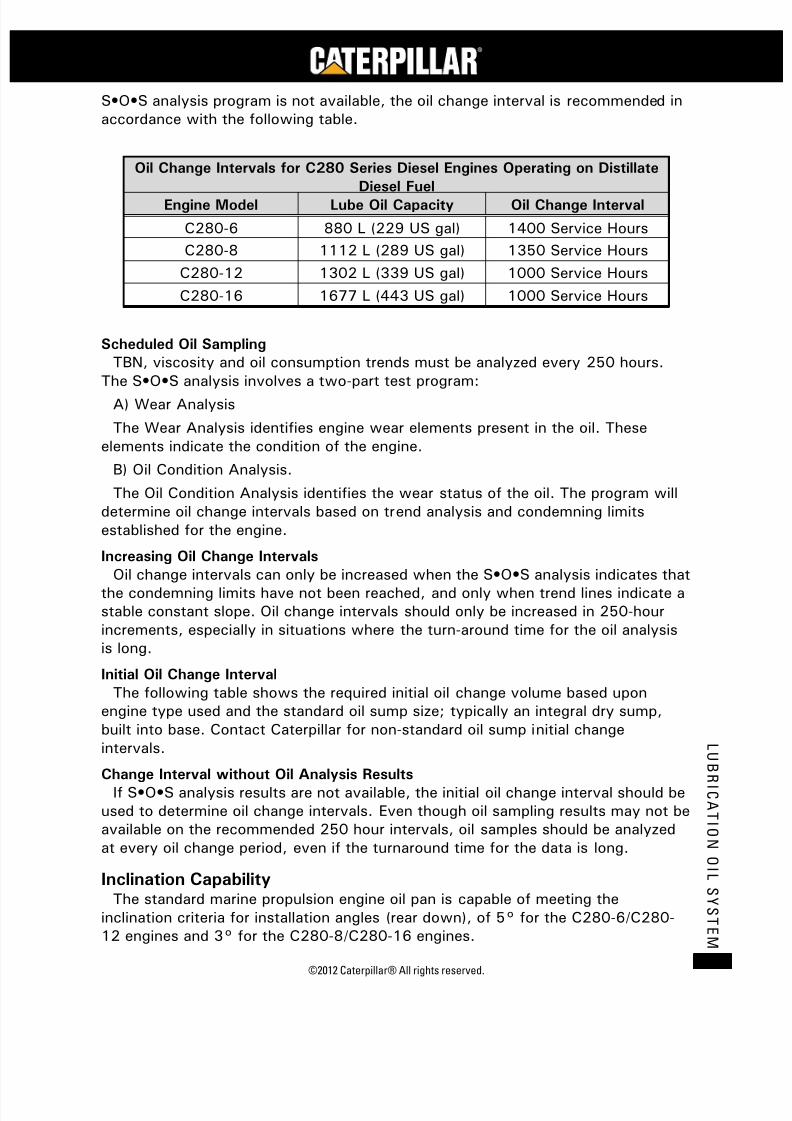
7/23/2019 1.- c280 Epa Tier 2 - Imo II Marine Project Guide
http://slidepdf.com/reader/full/1-c280-epa-tier-2-imo-ii-marine-project-guide 75/222
©2012 Caterpillar® All rights reserved. 67
L U
B R I C A T I O N
O I L S Y S T E M
S•O•S analysis program is not available, the oil change interval is recommended inaccordance with the following table.
Oil Change Intervals for C280 Series Diesel Engines Operating on Distillate
Diesel FuelEngine Model Lube Oil Capacity Oil Change Interval
C280-6 880 L (229 US gal) 1400 Service Hours
C280-8 1112 L (289 US gal) 1350 Service Hours
C280-12 1302 L (339 US gal) 1000 Service Hours
C280-16 1677 L (443 US gal) 1000 Service Hours
Scheduled Oil Sampling
TBN, viscosity and oil consumption trends must be analyzed every 250 hours.
The S•O•S analysis involves a two-part test program:A) Wear Analysis
The Wear Analysis identifies engine wear elements present in the oil. Theseelements indicate the condition of the engine.
B) Oil Condition Analysis.
The Oil Condition Analysis identifies the wear status of the oil. The program willdetermine oil change intervals based on trend analysis and condemning limitsestablished for the engine.
Increasing Oil Change Intervals
Oil change intervals can only be increased when the S•O•S analysis indicates thatthe condemning limits have not been reached, and only when trend lines indicate astable constant slope. Oil change intervals should only be increased in 250-hourincrements, especially in situations where the turn-around time for the oil analysisis long.
Initial Oil Change Interval
The following table shows the required initial oil change volume based uponengine type used and the standard oil sump size; typically an integral dry sump,built into base. Contact Caterpillar for non-standard oil sump initial changeintervals.
Change Interval without Oil Analysis ResultsIf S•O•S analysis results are not available, the initial oil change interval should be
used to determine oil change intervals. Even though oil sampling results may not beavailable on the recommended 250 hour intervals, oil samples should be analyzedat every oil change period, even if the turnaround time for the data is long.
Inclination CapabilityThe standard marine propulsion engine oil pan is capable of meeting the
inclination criteria for installation angles (rear down), of 5° for the C280-6/C280-12 engines and 3° for the C280-8/C280-16 engines.
7/23/2019 1.- c280 Epa Tier 2 - Imo II Marine Project Guide
http://slidepdf.com/reader/full/1-c280-epa-tier-2-imo-ii-marine-project-guide 76/222
C28
MARINE PROJECT GUIDE
©2012 Caterpillar® All rights reserved.68
L U B R I C A T I O N
O I L S Y S T
E M
For marine auxiliary engine applications, the Caterpillar packages utilize a shallowdry sump mounted on the engine, which gravity drains into a wet sump that isintegral to the base assembly. This design allows for a reduced engine roomfootprint, eliminates the need for a second lube oil pump and provides 15° staticand 25° dynamic tilt capability. For generators supplied by others, generator
manufacturer is responsible for providing any forced lubrication system that may berequired for their generator to meet tilt requirements. For higher tilt requirementscontact the factory.
Customer Piping Connections
Engine Connections
Oil Fill and Drain – 38 mm (1-1/2 in. 150# ANSI Flange)
Package Connections
Lube Oil Centrifuge – Inlet and Outlet Connections – 38 mm (1-1/2 in. 150#ANSI Flange)
Lube Oil System SchematicEngine internal and typical external lube oil systems are illustrated on the
schematic shown on the following page.
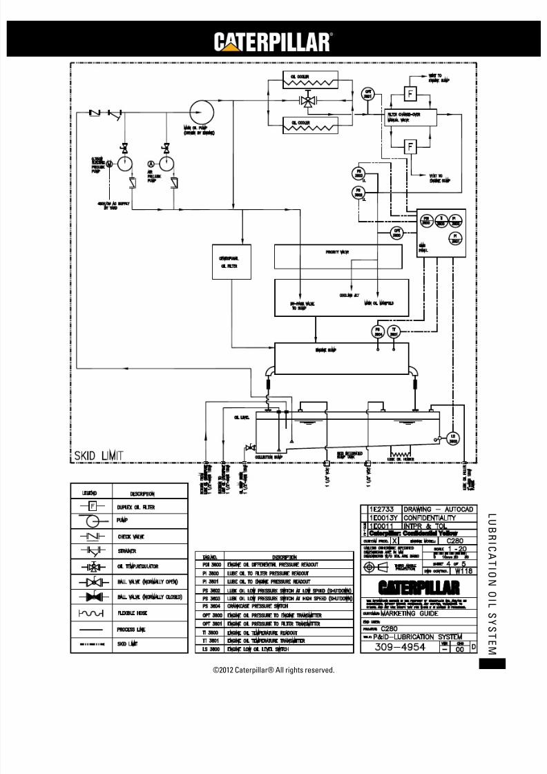
7/23/2019 1.- c280 Epa Tier 2 - Imo II Marine Project Guide
http://slidepdf.com/reader/full/1-c280-epa-tier-2-imo-ii-marine-project-guide 77/222
©2012 Caterpillar® All rights reserved. 69
L U
B R I C A T I O N
O I L S Y S T E M
7/23/2019 1.- c280 Epa Tier 2 - Imo II Marine Project Guide
http://slidepdf.com/reader/full/1-c280-epa-tier-2-imo-ii-marine-project-guide 78/222
C28
MARINE PROJECT GUIDE
©2012 Caterpillar® All rights reserved.70
C R A N K C A S E V E N T I L A T I
O N
S Y S T E M
Crankcase Ventilation System
Crankcase EmissionsCrankcase emissions result from combustion byproducts and/or exhaust fumes
escaping around the piston rings and into the crankcase, commonly called blow-by.If not controlled, this blow-by can contaminate the lube oil and pressurize thecrankcase, possibly leading to an oil leak.
Venting the emissions to the atmosphere is a simple solution to release thepressure and trapped fumes. Managing the emissions, however, adds complexity tocrankcase ventilation systems.
Vent tubes and crankcase breathers are currently provided on the C280 dieselengine and integral oil sump to allow this gas to escape. However, as emissionlaws become more stringent, it is inevitable that crankcase emissions will beincluded in total system emission values. In the future, ventilating crankcaseemissions to the atmosphere will be discouraged or prohibited.
Current C280 diesel engines still require that crankcase fumes be vented toatmosphere. A closed-loop, on-engine crankcase filtration system (ingestivesystem) for the C280 series diesel engine is currently not available. Contact thefactory for more details.
Crankcase Fumes DisposalDo not vent crankcase and integral oil sump fumes into the engine room. The oily
fumes will have a tendency to clog air filters.
Crankcase fumes should be discharged directly to the atmosphere through aventing system individual for each engine.
The engine has breathers located on each cylinder bank on the engine. Crankcasefumes vent pipes must be of sufficient size to prevent the buildup of excessivebackpressure in the crankcase. Blow-by on a new engine will be approximately0.02 m³/hr-bkW (0.5 ft³/hr bhp). The pipes should also be adequately sized toaccommodate a worn engine. Size the vent piping for 0.04 m³/hr-bkW (1.0 ft³/hrbhp) with a maximum of 13 mm H2O (0.5 in. H2O) pressure drop in the piping.Formulas for calculating backpressure can be found in the Crankcase Ventilationsection of the current Application and Installation Guide.
Loops or low points in a crankcase vent pipe must be avoided to prevent liquidlocks from the condensation in the pipe and thus restricting the discharge of fumes.Where horizontal runs are required, install the pipe with a gradual rise of 41.7mm/m, (½ in/ft) slope from the engine. The weight of the vent pipes will requireseparate off-engine supports as part of the installation design. Further additionalflexible connections will need to be installed to accommodate the enginemovement.
The pipe should vent directly into the atmosphere at a well-considered locationand be fitted with a gooseneck or similar arrangement to keep rain or water sprayfrom entering the engine. Consideration should also be given to other equipment

7/23/2019 1.- c280 Epa Tier 2 - Imo II Marine Project Guide
http://slidepdf.com/reader/full/1-c280-epa-tier-2-imo-ii-marine-project-guide 79/222
©2010 Caterpillar® All rights reserved. 71
C R A N K C A S
E V E N T I L A T I O N
S Y S T E M
located near the discharge area. If not located properly, the oil carryover canaccumulate over time and become unsightly.
An oil condensate trap, as shown on the following drawing, will minimize theamount of oil discharged from the vent pipe.
The crankcase pressure should not vary more than 25.4 mm H2O (1.0 in. H2O)of water from ambient barometric pressure. Measurement should be made at theengine dipstick location with the engine at operating temperature and minimum at80%-90% of rated load.Customer Piping Connections
Rubber boot for 60.3 mm (2.375 in.) O.D. tubing. In-line engines require 1 bootand vee engines require 2 boots.

7/23/2019 1.- c280 Epa Tier 2 - Imo II Marine Project Guide
http://slidepdf.com/reader/full/1-c280-epa-tier-2-imo-ii-marine-project-guide 80/222
C28
MARINE PROJECT GUIDE
©2012 Caterpillar® All rights reserved.72
C R A N K C A S E V E N T I L A T I
O N
S Y S T E M
Typical Crankcase Piping System

7/23/2019 1.- c280 Epa Tier 2 - Imo II Marine Project Guide
http://slidepdf.com/reader/full/1-c280-epa-tier-2-imo-ii-marine-project-guide 81/222
©2012 Caterpillar® All rights reserved. 73
C O O L I N G S Y S T E M
Fuel System
GeneralThe fuel system utilizes unit injectors to deliver the correct amount of fuel to the
cylinder at the precise moment it is needed, enabling the C280 diesel engine toproduce maximum power at maximum efficiency with a minimum of exhaustemissions.
Internal Fuel SystemThe main fuel system components are the engine driven transfer pump,
secondary duplex media type fuel filters (5 micron), fuel unit injectors and a fuelbackpressure regulator.
A manual fuel priming pump is also available. This pump is recommended if noelectrical priming pump is available.
Fuel Transfer Pump
The engine driven fuel transfer pump is a gear type pump that delivers the fuelthrough the filters to the injectors. The recommended delivery pressure to theinjectors is 800 to 840 kPa (116 to 122 psi) at rated load and speed for C280engines. The delivery pressure is controlled by adjusting the fuel pressure regulatorsetting on site during commissioning of the engine. The pump is equipped with apump mounted safety valve and the fuel flow at rated rpm is listed in the technicaldata and varies with engine speed. The pump is mounted on the left hand side.
Unit Injectors (EUI)
The electronically controlled fuel unit injectors combine the pumping, meteringand injecting elements into a single unit mounted in the cylinder head. Externalmanifolds supply low pressure fuel from the transfer pump to the cylinder heads.High pressure lines are not used. A 100 micron edge type filter is built into eachunit injector.
External Fuel System Design ConsiderationsDiesel fuel supply systems must ensure a continuous and clean supply of fuel to
the engine’s fuel system. The fuel system is designed for distillate fuel, requiringviscosity ranging from 1.4 cSt to 20 cSt at 38°C (100°F).The external fuel systemtypically has three major components: a fuel storage system, a fuel transfer systemand fuel filtration system; and each of these systems demand careful attention to
ensure the success of each installation. Fuel Storage System
Tank LocationThe tanks should not exceed the height of the engine fuel injectors in order to
prevent possible leakage of fuel into the cylinders. If a higher position isunavoidable, then an auxiliary fuel tank or head limiting tank may be required.Otherwise, check valves with backpressures set to the fuel column height must beinstalled. Caterpillar fuel transfer pumps lifting capability is equivalent to 40 kPa (6psi) inlet restriction.

7/23/2019 1.- c280 Epa Tier 2 - Imo II Marine Project Guide
http://slidepdf.com/reader/full/1-c280-epa-tier-2-imo-ii-marine-project-guide 82/222
C28
MARINE PROJECT GUIDE
©2012 Caterpillar® All rights reserved.74
C O O L I N G S Y S T E M
Fuel Transfer System
Line RestrictionThe piping carrying fuel to the fuel transfer pump and the return line carrying
excess fuel to the tank should be no smaller than the engine connections. Themaximum inlet flow restriction is 20 kPa (3 psi) at rated speed. Air in the systemcauses hard starting, erratic engine operation and will erode injectors.
Return LineThe return line should enter the top of the tank without shutoff valves. Bypass
(return) fuel leaving the engine pressure regulator should be returned to the engineday tank. If the return fuel is cooled and not returned to the day tank, provisionsmust be made to have the piping system vented for entrapped air and gasses.
Fuel Filtration System
Primary Fuel FilterCaterpillar recommends the use of a primary filter/strainer prior to the engine
transfer pump and offers a duplex, primary filter (178 micron) for this purpose.
Water SeparationCaterpillar also recommends the use of a water and sediment separator in the
supply line ahead of the transfer pump, and offers a Racor filter/water separator forthis purpose.
Miscellaneous Fuel System Considerations
Flexible ConnectionsConnections to the engine must be flexible hose and must be located directly at
the engine inlet and outlet to accommodate engine motion.
Fuel TemperatureEngines are power set at the factory with 30°C ± 3°C (86°F ±5°F) fuel to the
engine transfer pump. Higher fuel temperatures will reduce fuel stop powercapability. The “fuel stop” power reduction is 1% for each 5.6°C (10°F) fuelsupply temperature increase above 30°C (86°F). If the engine is operating belowthe “fuel stop” limit, the governor will add fuel as required to maintain the requiredengine speed. The classification societies have a maximum return to tank fueltemperature. This temperature is related to the fuel flash point. To obtain good fuelfilter life, the engine fuel supply temperature should be less than 40°C (104°F).The minimum allowable viscosity of the fuel entering the engine is 1.4 cSt.
Fuel CoolersThe need for fuel coolers is project specific and depends greatly on day tank size
and location. See the following table for fuel heat rejection data.

7/23/2019 1.- c280 Epa Tier 2 - Imo II Marine Project Guide
http://slidepdf.com/reader/full/1-c280-epa-tier-2-imo-ii-marine-project-guide 83/222
©2012 Caterpillar® All rights reserved. 75
C O O L I N G S Y S T E M
Fuel Cooler Fuel Flow and Heat Rejection
EngineRated Speed
rpm
Fuel Flow to
Engine
L/min (gal/min)
Fuel Heat
Rejection
kW (Btu/min)
C280-61000 41.5 (11.0) 12.5 (712)
900 38.0 (10.0) 11.0 (626)
C280-81000 41.5 (11.0) 16.7 (951)
900 38.0 (10.0) 14.6 (831)
C280-121000 78.5 (20.7) 25.0 (1423)
900 72.0 (19.0) 22.0 (1252)
C280-161000 78.5 (20.7) 33.3 (1895)
900 72.0 (19.0) 25.4 (1668)
Fuel RecommendationsThe fuels recommended for use in Caterpillar C280 series diesel engines are
normally No. 2-D diesel fuel and No. 2 fuel oil, although No. 1 grades are alsoacceptable. The following table lists worldwide fuel standards which meetCaterpillar requirements.
Fuel with CIMAC designation DB, commonly referred to as Marine Diesel Oil(MDO), is an acceptable fuel, provided the fuel complies with Caterpillar fuelrecommendations.
Worldwide Fuel Standards1
Standard Name Description
American
ASTM D975No. 1-D and No. 2-DDiesel Fuel Oils
ASTM D396 No. 1 and No. 2 Fuel Oils
ASTM D2880No. 1-GT and No. 2-GTGas Turbine Fuels
BritishBS 2869
Classes A1, A2 and B2Engine Fuels
BS 2869 Classes C2 and D Burner Fuels
West GermanDIN 51601 Diesel Fuel
DIN 51603 Heating Oil ElAustralian AS 3570 Automotive Diesel Fuel
Japanese JIS K2204 Types 1 (spl), 1, 2, 3, and 3 (spl) Gas Oil
U.S. GovernmentW-F-800C
DF-1, DF-2 Conus andDF-20 Conus Diesel Fuel
W-F-815C FS-1 and FS-2 Burner Fuel Oil
U.S. Military MIL-L-16884G Marine Oil1. These fuel standards are usually acceptable, but are subject to change. The distillate fuel chartfor acceptable limits should be used as the guide for any fuel whether it’s listed in this chart or not(consult Caterpillar A&I for acceptability of any other fuels).
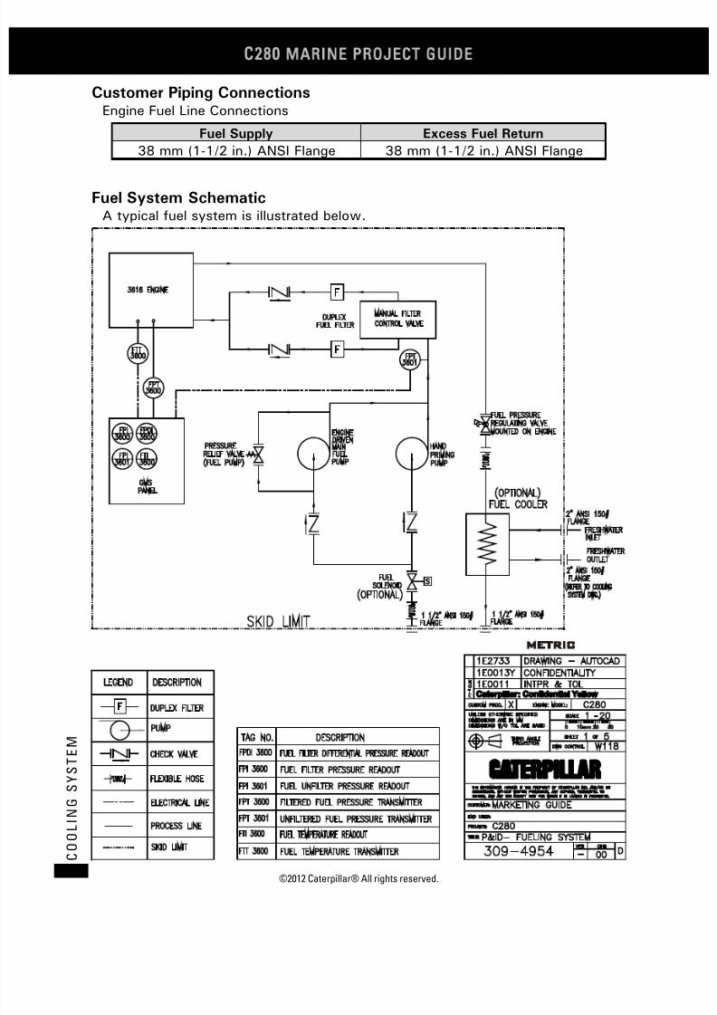
7/23/2019 1.- c280 Epa Tier 2 - Imo II Marine Project Guide
http://slidepdf.com/reader/full/1-c280-epa-tier-2-imo-ii-marine-project-guide 84/222
C28
MARINE PROJECT GUIDE
©2012 Caterpillar® All rights reserved.76
C O O L I N G S Y S T E M
Customer Piping ConnectionsEngine Fuel Line Connections
Fuel Supply Excess Fuel Return
38 mm (1-1/2 in.) ANSI Flange 38 mm (1-1/2 in.) ANSI Flange
Fuel System SchematicA typical fuel system is illustrated below.

7/23/2019 1.- c280 Epa Tier 2 - Imo II Marine Project Guide
http://slidepdf.com/reader/full/1-c280-epa-tier-2-imo-ii-marine-project-guide 85/222
©2012 Caterpillar® All rights reserved. 77
C O O L I N G S Y S T E M
Cooling System
GeneralThe cooling system configuration for the Caterpillar C280 series diesel engine in
marine applications can be either the separate circuit system or the combined
circuit system, also referred to as the single circuit - two pump system. Theselection of either of these systems is based on several criteria:
1. Applicable emission requirements, i.e. EPA Tier 2 or IMO.
2. Available sea water temperature.
The heat rejection data in this project guide are based on 32°C water to theaftercooler and 45°C air to the turbocharger inlet. The cooling system is laid outfor the following temperature levels:
1. 32°C (90°F) nominal water temperature to the aftercooler and oil cooler(IMO allows 32°C water with 25°C ambient sea water; and EPA Tier 2
requires 32°C water with 27°C ambient sea water). Refer to the HeatExchanger Sizing Requirements for C280 Engines chart on page 78.
2. 90°C (194°F) nominal jacket water temperature to the cylinder block (93°Cthermostatic valve is used for heat recovery applications).
3. 85°C (185°F) nominal oil temperature to bearings.
Internal Cooling System
Fresh Water Pumps
The C280 engine has two identical gear-driven centrifugal water pumps mountedon the front housing. The right-hand pump (viewed from the flywheel end) supplies
coolant to the block and heads. The left-hand pump supplies coolant to theaftercooler and oil cooler.
External Cooling System Design Considerations
Coolant Flow Control
The correct coolant flows are obtained by factory installed orifices on the engine,combined with proper external circuit resistance set at each site duringcommissioning, either with customer installed orifices or balancing valves, althougha lockable plug valve is recommended. The external circuit resistance settingestablishes the total circuit flow by balancing total circuit losses with the
characteristic pump performance curves. Correct external resistance is veryimportant. Too high a resistance will result in reduced flows to the aftercooler andoil cooler, and their effectiveness will decrease. If there is too low a resistance, thefluid velocity limits may be exceeded, and cavitation / early wear could be theresult.
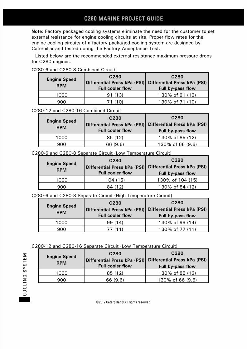
7/23/2019 1.- c280 Epa Tier 2 - Imo II Marine Project Guide
http://slidepdf.com/reader/full/1-c280-epa-tier-2-imo-ii-marine-project-guide 86/222
C28
MARINE PROJECT GUIDE
©2012 Caterpillar® All rights reserved.78
C O O L I N G S Y S T E M
Note: Factory packaged cooling systems eliminate the need for the customer to setexternal resistance for engine cooling circuits at site. Proper flow rates for theengine cooling circuits of a factory packaged cooling system are designed byCaterpillar and tested during the Factory Acceptance Test.
Listed below are the recommended external resistance maximum pressure drops
for C280 engines.
C280-6 and C280-8 Combined Circuit
Engine Speed
RPM
C280
Differential Press kPa (PSI)
Full cooler flow
C280
Differential Press kPa (PSI)
Full by-pass flow
1000 91 (13) 130% of 91 (13)
900 71 (10) 130% of 71 (10)
C280-12 and C280-16 Combined Circuit
Engine Speed
RPM
C280Differential Press kPa (PSI)
Full cooler flow
C280Differential Press kPa (PSI)
Full by-pass flow
1000
85 (12)
130% of 85 (12)
900 66 (9.6) 130% of 66 (9.6)
C280-6 and C280-8 Separate Circuit (Low Temperature Circuit)
Engine Speed
RPM
C280
Differential Press kPa (PSI)
Full cooler flow
C280
Differential Press kPa (PSI)
Full by-pass flow
1000
104 (15)
130% of 104 (15)
900 84 (12) 130% of 84 (12)
C280-6 and C280-8 Separate Circuit (High Temperature Circuit)
Engine Speed
RPM
C280
Differential Press kPa (PSI)
Full cooler flow
C280
Differential Press kPa (PSI)
Full by-pass flow
1000 99 (14) 130% of 99 (14)
900 77 (11) 130% of 77 (11)
C280-12 and C280-16 Separate Circuit (Low Temperature Circuit)
Engine Speed
RPM
C280
Differential Press kPa (PSI)
Full cooler flow
C280
Differential Press kPa (PSI)
Full by-pass flow
1000 85 (12) 130% of 85 (12)
900 66 (9.6) 130% of 66 (9.6)

7/23/2019 1.- c280 Epa Tier 2 - Imo II Marine Project Guide
http://slidepdf.com/reader/full/1-c280-epa-tier-2-imo-ii-marine-project-guide 87/222
©2012 Caterpillar® All rights reserved. 79
C O O L I N G S Y S T E M
C280-12 and C280-16 Separate Circuit (High Temperature Circuit)
Engine Speed
RPM
C280
Differential Press kPa (PSI)
Full cooler flow
C280
Differential Press kPa (PSI)
Full by-pass flow
1000
103 (15)
130% of 103 (15)
900 81 (12) 130% of 81 (12)
Coolant Temperature Control
The C280 engine uses fluid inlet control temperature regulators to provideuniform coolant temperature to the aftercooler, oil cooler, and cylinder block. Forthe combined circuit system, the AC/OC circuit is externally regulated to provide anominal 32°C (90°F) coolant temperature. The high temperature jacket watersystem uses the AC/OC outlet water to maintain 90°C (194°F) inlet water to theblock. For the separate circuit system, both the AC/OC and jacket water systemsare externally regulated, using sea water to maintain the required 32°C (90°F)
AC/OC and 90°C (194°F) jacket water temperatures.Sea Water Pump (customer furnished)
The seawater pump is typically supplied by the customer because the optionallysupplied Caterpillar engine mounted sea water pump does not have sufficientsuction capability to lift water from sea level to the engine room on a typicaloffshore platform.
Expansion Tanks
Expansion tanks are available from Caterpillar as standard options. The combinedcircuit expansion tank is full flow. The separate circuit expansion tank is full flowfor the jacket water circuit and the AC/OC circuit is a shunt type connection. Note
that a single expansion tank is used to provide water and venting for both circuits.
System Capacities
Engine
Engine
Coolant
Volume
Expansion TankExpansion
Tank Piping
Heat
ExchangerStandard
Capacity
Increased
Capacity
Liters (kg)
C280-6 400 (400) 300 (300) 475 (475) 150 (150) 50 (50)
C280-8 530 (530) 300 (300) 475 (475) 150 (150) 50 (50)
C280-12 800 (800) 300 (300) 475 (475) 200 (200) 100 (100)
C280-16 1060 (1060) 300 (300) 475 (475) 200 (200) 100 (100)
U.S. Gallons (lb)
C280-6 105 (875) 80 (667) 125 (1042) 40 (333) 15 (125)
C280-8 140 (1167) 80 (667) 125 (1042) 40 (333) 15 (125)
C280-12 210 (1751) 80 (667) 125 (1042) 55 (441) 30 (250)
C280-16 280 (2334) 80 (667) 125 (1042) 55 (441) 30 (250)

7/23/2019 1.- c280 Epa Tier 2 - Imo II Marine Project Guide
http://slidepdf.com/reader/full/1-c280-epa-tier-2-imo-ii-marine-project-guide 88/222
C28
MARINE PROJECT GUIDE
©2012 Caterpillar® All rights reserved.80
C O O L I N G S Y S T E M
Heat Exchangers
Caterpillar offers heat exchangers of the plate and frame type. Heat exchangersizing and performance depends on emission requirements, water flow andtemperature differential. Control of the sea water velocity must be maintained toavoid erosion problems with the heat exchangers.
Heat Exchanger Sizing
The minimum acceptable heat exchanger configuration for either the separatecircuit system or combined circuit system must provide coolant temperature at theAC/OC pump inlet in accordance with applicable emission requirements, and mustconsider the following:
1. Maximum expected ambient temperature
2. Maximum engine power capability (rack stop setting)
3. Maximum expected sea-water temperature
4. Expected sea-water fouling factor
5. Anticipated coolant composition (i.e. 50% glycol).
See the technical data section of this project guide for specific heat rejectionfigures. For more reference, refer to the following Heat Exchanger Sizing Chart.

7/23/2019 1.- c280 Epa Tier 2 - Imo II Marine Project Guide
http://slidepdf.com/reader/full/1-c280-epa-tier-2-imo-ii-marine-project-guide 89/222
©2012 Caterpillar® All rights reserved. 81
C O O L I N G S Y S T E M
Jacket Water Heaters
Jacket water heaters may be required to meet cold starting and load acceptancecriteria. To provide for the optimum usage of the heater, Caterpillar routes theheater water into the top of the cylinder block and exit at the bottom to maintainblock temperature. Caterpillar offers an optional 15 kW heater for C280-06 engine
installations, and a 30 kW heater for C280-08 and larger engine installations.System Pressures
Correct cooling system pressure minimizes pump cavitation and increases pumpefficiency. The combination of static and dynamic pressure heads must meet thepressure criteria listed in the technical data.
Venting
Proper venting is required for all applications. Vent lines should be routed to anexpansion tank at a constant upward slope.
System Monitoring
During the design and installation phase it is important that provisions are madeto measure pressure and temperature differentials across major systemcomponents. This allows accurate documentation of the cooling system during thecommissioning procedure. Future system problems or component deterioration(such as fouling) are easier to identify if basic data is available.
Serviceability
Suitable access should be provided for cleaning, removal or replacement of allsystem components. Isolation valves should be installed as deemed necessary tofacilitate such work.
System Pressures and Velocities
The following pressure and velocity limits apply to C280 series engines:
Water Pump Pressures
Maximum allowable Static Head 145 kPa (21 psi)
Minimum AC/OC Inlet Pressure (dynamic)
-5 kPa (-0.7 psi)
Minimum JW inlet Pressure (dynamic) 30 kPa (4 psi)
Minimum Sea Water Inlet Pressure (dynamic) -5 kPa (-0.7 psi)
Maximum Operating Pressures
Engine Cooling Circuits 500 kPa (73 psi)
Caterpillar Expansion Tanks
150 kPa (22 psi)
Heat Exchangers Type Specific
Water Velocities
Pressurized Lines 4.5 m/s (15 ft/s)
Pressurized Thin Walled Tubes
2.0 to 2.5 m/s (7 to 8 ft/s)
Suction Lines (Pump Inlet) 1.5 m/s (5 ft/s)
Low Velocity De-aeration Line 0.6 m/s (2 ft/s)

7/23/2019 1.- c280 Epa Tier 2 - Imo II Marine Project Guide
http://slidepdf.com/reader/full/1-c280-epa-tier-2-imo-ii-marine-project-guide 90/222
C28
MARINE PROJECT GUIDE
©2012 Caterpillar® All rights reserved.82
C O O L I N G S Y S T E M
Jacket Water and AC/OC Pump
C280-6/8 Engines
PN: 7E-8180, 304-4942
Jacket Water and AC/OC Pump
C280-12 & C280-16 Engines
PN: 7E-8181, 304-4948

7/23/2019 1.- c280 Epa Tier 2 - Imo II Marine Project Guide
http://slidepdf.com/reader/full/1-c280-epa-tier-2-imo-ii-marine-project-guide 91/222
©2012 Caterpillar® All rights reserved. 83
C O O L I N G S Y S T E M
Sea Water Pump
C280 Engines
PN: 7E8182, 204-4957
High Capacity Sea Water Pump
C280-16 Engines
PN: 130-6765 (CW, Rev. Rotation); PN: 130-6771 (CCW, Std. Rotation)
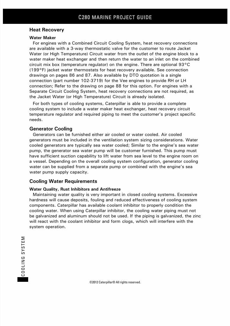
7/23/2019 1.- c280 Epa Tier 2 - Imo II Marine Project Guide
http://slidepdf.com/reader/full/1-c280-epa-tier-2-imo-ii-marine-project-guide 92/222
C28
MARINE PROJECT GUIDE
©2012 Caterpillar® All rights reserved.84
C O O L I N G S Y S T E M
Heat Recovery
Water Maker
For engines with a Combined Circuit Cooling System, heat recovery connectionsare available with a 3-way thermostatic valve for the customer to route Jacket
Water (or High Temperature) Circuit water from the outlet of the engine block to awater maker heat exchanger and then return the water to an inlet on the combinedcircuit mix box (temperature regulator) on the engine. There are optional 93°C(199°F) jacket water thermostats for heat recovery available. See connectiondrawings on pages 86 and 87. Also available by DTO quotation is a singleconnection (part number 102-3719) for the Vee engines to provide RH or LHconnection; Refer to the drawing on page 88 for this option. For engines with aSeparate Circuit Cooling System, heat recovery connections are not required, asthe Jacket Water (or High Temperature) Circuit is already isolated.
For both types of cooling systems, Caterpillar is able to provide a completecooling system to include a water maker heat exchanger, heat recovery circuittemperature regulator and required piping to meet the customer’s project specificneeds.
Generator CoolingGenerators can be furnished either air cooled or water cooled. Air cooled
generators must be included in the ventilation system sizing considerations. Watercooled generators are typically sea water cooled; Similar to the engine’s sea waterpump, the generator sea water pump will be customer furnished. This pump musthave sufficient suction capability to lift water from sea level to the engine room ona vessel. Depending on the overall cooling system configuration, generator cooling
water can be supplied from a separate pump or combined with the engine’s seawater pump supply capacity.
Cooling Water Requirements
Water Quality, Rust Inhibitors and Antifreeze
Maintaining water quality is very important in closed cooling systems. Excessivehardness will cause deposits, fouling and reduced effectiveness of cooling systemcomponents. Caterpillar has available coolant inhibitor to properly condition thecooling water. When using Caterpillar inhibitor, the cooling water piping must notbe galvanized and aluminum should not be used. If the piping is galvanized, the zincwill react with the coolant inhibitor and form clogs, which will interfere with thesystem operation.

7/23/2019 1.- c280 Epa Tier 2 - Imo II Marine Project Guide
http://slidepdf.com/reader/full/1-c280-epa-tier-2-imo-ii-marine-project-guide 93/222
©2012 Caterpillar® All rights reserved. 85
C O O L I N G S Y S T E M
Customer Piping Connections
Engine Connections
Engine Cooling Water Inlet/Outlet 6 in. ANSI Flange
Engine Sea Water Inlet/Outlet 6 in. ANSI Flange
Generator Cooling Water Inlet/Outlet
DN50, DIN 2633 Flange
Water Maker Supply/Return 4 in. ANSI Flange
Marine Gear Cooling(optional Part Number 211-0261)
2½-12 THD with 37° flarefor 50.8 mm (2 in.) Tube
Package Connections
Package Sea Water Inlet/Outlet 6 in. ANSI Flange
Available in CAT standard, ANSI standard, or DIN standard. CAT standard weldflanges at every connection point, ANSI or DIN can be furnished.
Cooling System SchematicsTypical Combined Circuit and Separate Circuit Cooling Systems are illustrated on
pages 84 and 85.
Watermaker connections for heat recovery are shown on pages 86 through 88.
Water flow path through the engine is shown on pages 89 through 92 andcustomer connections configurations and sizes are shown on pages 93 through 96showing emergency connections and standard connections.
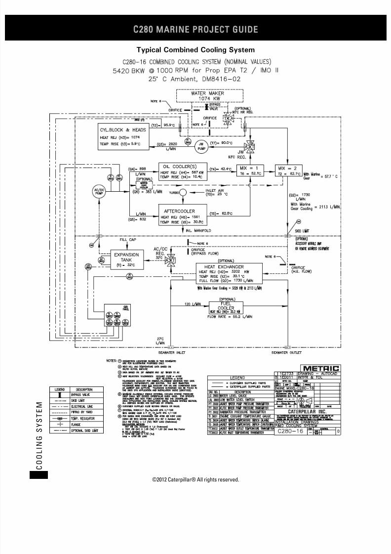
7/23/2019 1.- c280 Epa Tier 2 - Imo II Marine Project Guide
http://slidepdf.com/reader/full/1-c280-epa-tier-2-imo-ii-marine-project-guide 94/222
C28
MARINE PROJECT GUIDE
©2012 Caterpillar® All rights reserved.86
C O O L I N G S Y S T E M
Typical Combined Cooling System

7/23/2019 1.- c280 Epa Tier 2 - Imo II Marine Project Guide
http://slidepdf.com/reader/full/1-c280-epa-tier-2-imo-ii-marine-project-guide 95/222
©2012 Caterpillar® All rights reserved. 87
C O O L I N G S Y S T E M
Typical Separate Circuit Cooling System

7/23/2019 1.- c280 Epa Tier 2 - Imo II Marine Project Guide
http://slidepdf.com/reader/full/1-c280-epa-tier-2-imo-ii-marine-project-guide 96/222
C28
MARINE PROJECT GUIDE
©2012 Caterpillar® All rights reserved.88
C O O L I N G S Y S T E M
Inline Engines Watermaker Connections

7/23/2019 1.- c280 Epa Tier 2 - Imo II Marine Project Guide
http://slidepdf.com/reader/full/1-c280-epa-tier-2-imo-ii-marine-project-guide 97/222
©2012 Caterpillar® All rights reserved. 89
C O O L I N G S Y S T E M
Vee Engines Watermaker Connections

7/23/2019 1.- c280 Epa Tier 2 - Imo II Marine Project Guide
http://slidepdf.com/reader/full/1-c280-epa-tier-2-imo-ii-marine-project-guide 98/222
C28
MARINE PROJECT GUIDE
©2012 Caterpillar® All rights reserved.90
C O O L I N G S Y S T E M
Optional Vee Engines Watermaker Connections
(Part Number 102-3719)

7/23/2019 1.- c280 Epa Tier 2 - Imo II Marine Project Guide
http://slidepdf.com/reader/full/1-c280-epa-tier-2-imo-ii-marine-project-guide 99/222
©2012 Caterpillar® All rights reserved. 91
C O O L I N G S Y S T E M
C280-6 and C280-8 Combined Cooling Schematic
1. Aftercooler/Oil Cooler Pump
2. Aftercooler
3. Jacket Water Pump
4. Oil Coolers
5. Thermostat Housing
6. Bypass Line
7. Water From Heads
8. Water To Block
9. Turbocharger
10. Vent Line
11. Emergency Water Connection

7/23/2019 1.- c280 Epa Tier 2 - Imo II Marine Project Guide
http://slidepdf.com/reader/full/1-c280-epa-tier-2-imo-ii-marine-project-guide 100/222
C28
MARINE PROJECT GUIDE
©2012 Caterpillar® All rights reserved.92
C O O L I N G S Y S T E M
C280-12 and C280-16 Combined Cooling Schematic
1. Aftercooler/Oil Cooler Pump
2. Aftercoolers
3. Jacket Water Pump
4. Oil Coolers (2) *
5. Thermostat Housing
6. Water Manifold
7. Bypass Line
8. Water From Heads
9. Water To Block
10. Turbochargers
11. Emergency Water Connection
* Three coolers required on some applications.

7/23/2019 1.- c280 Epa Tier 2 - Imo II Marine Project Guide
http://slidepdf.com/reader/full/1-c280-epa-tier-2-imo-ii-marine-project-guide 101/222
©2012 Caterpillar® All rights reserved. 93
C O O L I N G S Y S T E M
C280-6 and C280-8 Separate Circuit Cooling Schematic
1. Aftercooler/Oil Cooler Pump
2. Aftercooler
3. Jacket Water Pump
4. Oil Coolers
5. Water Manifold
6. Water From Heads
7. Water To Block
8. Turbocharger
9. Emergency Water Connection10. Vent Line

7/23/2019 1.- c280 Epa Tier 2 - Imo II Marine Project Guide
http://slidepdf.com/reader/full/1-c280-epa-tier-2-imo-ii-marine-project-guide 102/222
C28
MARINE PROJECT GUIDE
©2012 Caterpillar® All rights reserved.94
C O O L I N G S Y S T E M
C280-12 and C280-16 Separate Circuit Cooling Schematic
1. Aftercooler/Oil Cooler Pump
2. Aftercoolers
3. Jacket Water Pump
4. Oil Coolers (2) *
5. Outlet Housing
6. Water Manifold
7. Emergency Water Connection
8. Water From Heads
9. Water To Block
10. Turbochargers
* Three coolers required on some applications.
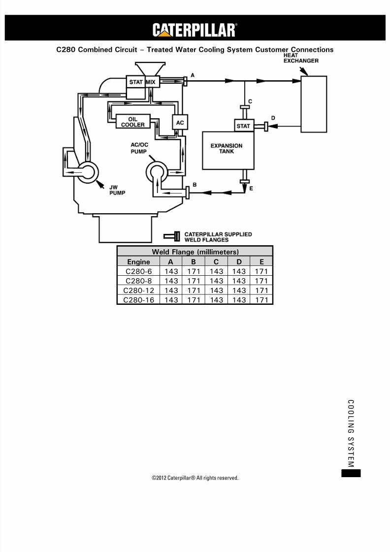
7/23/2019 1.- c280 Epa Tier 2 - Imo II Marine Project Guide
http://slidepdf.com/reader/full/1-c280-epa-tier-2-imo-ii-marine-project-guide 103/222
©2012 Caterpillar® All rights reserved. 95
C O O L I N G S Y S T E M
C280 Combined Circuit – Treated Water Cooling System Customer Connections
Weld Flange (millimeters)
Engine A B C D E
C280-6 143 171 143 143 171
C280-8 143 171 143 143 171
C280-12 143 171 143 143 171
C280-16 143 171 143 143 171

7/23/2019 1.- c280 Epa Tier 2 - Imo II Marine Project Guide
http://slidepdf.com/reader/full/1-c280-epa-tier-2-imo-ii-marine-project-guide 104/222
C28
MARINE PROJECT GUIDE
©2012 Caterpillar® All rights reserved.96
C O O L I N G S Y S T E M
C280 Combined Circuit – Treated Water Cooling System with Auxiliary Pumps
Customer Connections
Weld Flange (millimeters)Engine A B C D E F G H I J K
C280-6 143 116 116 171 171 143 116 143 143 143 171
C280-8 143 116 116 171 171 143 116 143 143 143 171
C280-12 143 143 143 171 171 143 143 171 143 143 171
C280-16 143 143 143 171 171 143 143 171 143 143 171

7/23/2019 1.- c280 Epa Tier 2 - Imo II Marine Project Guide
http://slidepdf.com/reader/full/1-c280-epa-tier-2-imo-ii-marine-project-guide 105/222
©2012 Caterpillar® All rights reserved. 97
C O O L I N G S Y S T E M
C280 Separate Circuit – Treated Water Cooling System Customer Connections
Weld Flange (millimeters)
Engine A B C D E F G
C280-6 116 171 171 143 143 143 171
C280-8 116 171 171 143 143 143 171
C280-12 143 171 171 143 143 143 171
C280-16 143 171 171 143 143 143 171

7/23/2019 1.- c280 Epa Tier 2 - Imo II Marine Project Guide
http://slidepdf.com/reader/full/1-c280-epa-tier-2-imo-ii-marine-project-guide 106/222
C28
MARINE PROJECT GUIDE
©2012 Caterpillar® All rights reserved.98
C O O L I N G S Y S T E M
C280 Separate Circuit – Treated Water Cooling System with Auxiliary Pumps
Customer Connections
Weld Flange (millimeters)
Engine A B C D E F G H I J K
C280-6 116 116 116 171 171 110 110 143 143 143 171
C280-8 116 116 116 171 171 110 110 143 143 143 171
C280-12 143 143 143 171 171 143 143 143 143 143 171
C280-16 143 143 143 171 171 143 143 143 143 143 171

7/23/2019 1.- c280 Epa Tier 2 - Imo II Marine Project Guide
http://slidepdf.com/reader/full/1-c280-epa-tier-2-imo-ii-marine-project-guide 107/222
©2012 Caterpillar® All rights reserved. 99
S T A R T I N G A I R S Y S T E M
Starting Air System
GeneralThe Caterpillar C280 Series engine supplied air starting system includes TDI
turbine type air starters, air relay valve, solenoid valve, strainer, shut off valve andoptional pressure regulator, if required. One TDI turbine type air starter is neededfor inline and 12 cylinder engines, while two are needed for the 16 cylinderengines. For starting with gear boxes and drive line loads attached to the enginethere are optional dual starters for the 12 cylinder and Heavy Duty single startersavailable for the inline engines. The turbine driven air motor is highly reliable,tolerant of debris and does not require external lubrication.
Engine Starting Air SystemThe standard TDI turbine starters operate on air inlet pressures from 6.2 to 10.4
bar (90 to 150 psi). These pressures are required at the starter inlet port. An air
tank pressure below 7 bar (100 psi) will generally not start the engine because ofthe pressure drop associated with the air supply lines. For initial system evaluation,assume a 2 bar (29 psi) pressure drop between the tank and the air starter inlet.
A pressure regulator (available as an option in the pricelist) is necessary when thesupply pressure exceeds the starter dynamic operating pressure. The pressureregulator should be set from 6.2 to 10.4 bar (90 to 150 psi). Inline engines shouldhave the capacity to flow 450 l/sec (15.9 ft3/sec) per starter at regulator inletpressure of (90 psi) (regulators with a Cv factor of 40 or higher are required).
The quantity of air required for each start and the size of the air receiver dependupon cranking time and air-starter consumption. A typical first start at 25°C (77°F)
ambient will take five to seven seconds. Restarts of warm engines normally takeplace in three to four seconds. The control system will shut off the air to the airstarters at 170 rpm engine speed. At this firing speed, the governor is activated toallow fuel to the engine.
Large or complex drive lines can increase starting air volume required by 20 or 30percent depending on loads on the engine during starting. Gearbox designs canhave a significant impact on the starting loads if connected during startingespecially if driving a shaft driven generator.
Starting Air System Design Considerations
The following charts are for estimating typical air receiver sizing for startinganengine only. The chart shows the estimated number of starts available with aninitial starting air receiver pressure as shown on the curves. The starting airreceiver size is normally determined by the requirements of the classificationsociety for the number of starts or start attempts. Refer to the Air Supply LineSizing section for additional information.
The size of the air receivers should be increased if the starting air receiver alsosupplies air for purposes other than the main engine starting (e.g. engine airprelube, work air, auxiliary gensets). The Caterpillar intermittent air prelube pumpconsumption rate is 28.2 l/sec (1 ft3/sec) based on free air at 21°C at 100 kPa

7/23/2019 1.- c280 Epa Tier 2 - Imo II Marine Project Guide
http://slidepdf.com/reader/full/1-c280-epa-tier-2-imo-ii-marine-project-guide 108/222
C28
MARINE PROJECT GUIDE
©2012 Caterpillar® All rights reserved.100
S T A R T I N G A I R S Y S T E M
(77°F at 76 psi). The pump motor operating pressure is 690 kPa (100 psi). Withthe redundant prelube system and the continuous prelube pump running at startup,the pneumatic intermittent prelube pumps for the engine and generator will operatefor no longer than 15 seconds. For generator sets with pneumatic intermittentprelube pump only, the prelube pump will normally operate 1 to 5 minutes before
the engine begins to crank.
0
100
200
300
400
500
600
700
800
900
1000
1100
12001300
1400
1500
1600
0 1 2 3 4 5 6 7 8 9
V e e E n g i n e s T a n k V o l u m e ( g a l )
Number of Starts
Assuming 5 second starts @ 90 psi (6.2 bar) at starter inlet
Requires 40 Cv regulator & 300 mesh strainer for pressures above 200 psi
Add additional capacity for higher loads
145 psi (10 bar)
200 psi (14 bar)
230 psi (16 bar)
290 psi (20 bar)
435 psi (30 bar)
580 psi (40 bar)
Tank
pressure

7/23/2019 1.- c280 Epa Tier 2 - Imo II Marine Project Guide
http://slidepdf.com/reader/full/1-c280-epa-tier-2-imo-ii-marine-project-guide 109/222
©2012 Caterpillar® All rights reserved. 101
S T A R T I N G A I R S Y S T E M
T a
n k V o l u m e ( g a l )
Number of Starts
Assuming 5 seconds start @ 90psi (6.2 bar) pressure at starter inlet
Require 40 Cv regulator & 300 mesh strainer for pressures above 200 psi
Add additional capacity for higher loads
150 psi (10.3 bar)
200 psi (13.8 bar)
250 psi (17.2 bar)
300 psi (20.7 bar)
400 psi (27.6 bar)600 psi (41.4 bar)
Tank
pressure

7/23/2019 1.- c280 Epa Tier 2 - Imo II Marine Project Guide
http://slidepdf.com/reader/full/1-c280-epa-tier-2-imo-ii-marine-project-guide 110/222
C28
MARINE PROJECT GUIDE
©2012 Caterpillar® All rights reserved.102
S T A R T I N G A I R S Y S T E M
0
100
200
300
400
500
600
700
800
900
1000
1100
1200
1300
1400
1500
1600
1700
1800
1900
2000
0 1 2 3 4 5 6 7 8 9 10
T a n k V o l u m
e ( g a l )
Number of Starts
Air tank sizing C280-12 or 16 engine ONLY with Dual Starters
Assuming 4 seconds start @ 90 psi (6.2 bar) at starter inlet
Requires quanty(2) 40 Cv regulators and 300 mesh strainers for tank pressures above 200 psi
Add additional capacity for higher loads
150 psi (10.3 bar)
200 psi (13.8 bar)
250 psi (17.2 bar)
300 psi (20.7 bar)
350 psi (24.1 bar)
400 psi (27.6 bar)
600 psi (41.4 bar)
Tank
pressure
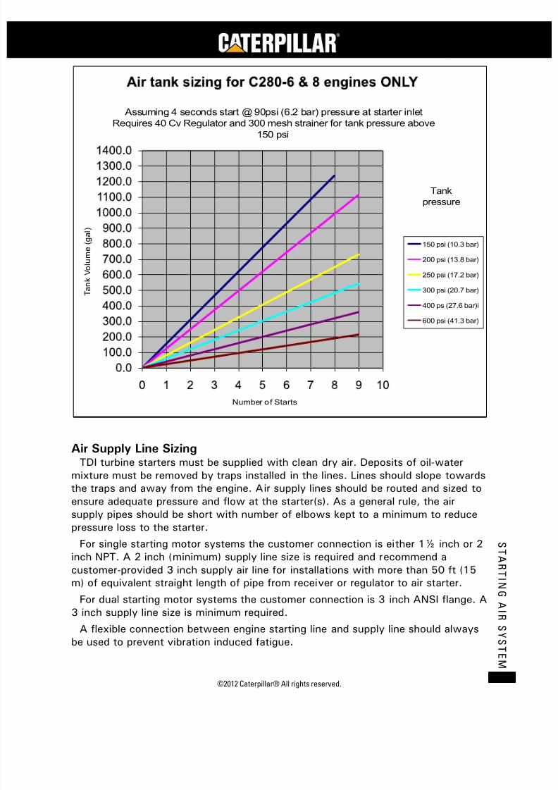
7/23/2019 1.- c280 Epa Tier 2 - Imo II Marine Project Guide
http://slidepdf.com/reader/full/1-c280-epa-tier-2-imo-ii-marine-project-guide 111/222
©2012 Caterpillar® All rights reserved. 103
S T A R T I N G A I R S Y S T E M
T a n k V o l u m e ( g a l )
Number of Starts
Assuming 4 seconds start @ 90psi (6.2 bar) pressure at starter inlet
Requires 40 Cv Regulator and 300 mesh strainer for tank pressure above
150 psi
150 psi (10.3 bar)
200 psi (13.8 bar)
250 psi (17.2 bar)
300 psi (20.7 bar)
400 ps (27.6 bar)i
600 psi (41.3 bar)
Tank
pressure
Air Supply Line SizingTDI turbine starters must be supplied with clean dry air. Deposits of oil-water
mixture must be removed by traps installed in the lines. Lines should slope towardsthe traps and away from the engine. Air supply lines should be routed and sized toensure adequate pressure and flow at the starter(s). As a general rule, the airsupply pipes should be short with number of elbows kept to a minimum to reducepressure loss to the starter.
For single starting motor systems the customer connection is either 1½ inch or 2inch NPT. A 2 inch (minimum) supply line size is required and recommend acustomer-provided 3 inch supply air line for installations with more than 50 ft (15m) of equivalent straight length of pipe from receiver or regulator to air starter.
For dual starting motor systems the customer connection is 3 inch ANSI flange. A3 inch supply line size is minimum required.
A flexible connection between engine starting line and supply line should alwaysbe used to prevent vibration induced fatigue.

7/23/2019 1.- c280 Epa Tier 2 - Imo II Marine Project Guide
http://slidepdf.com/reader/full/1-c280-epa-tier-2-imo-ii-marine-project-guide 112/222
C28
MARINE PROJECT GUIDE
©2012 Caterpillar® All rights reserved.104
S T A R T I N G A I R S Y S T E M
If a pressure reducing valve is required, a valve with Cv40 should be used toprovide sufficient air flow. Locate the pressure reducing valve as close to theengine as possible to minimize the air pressure reduction valve supply pipediameter. Water and oil must be removed frequently from air supply source toprevent possible damage to the starting system components.
Starting Air System SchematicA typical starting air system is illustrated below.
Starting Air System with Emergency Shutoff and Oil Mist Detector

7/23/2019 1.- c280 Epa Tier 2 - Imo II Marine Project Guide
http://slidepdf.com/reader/full/1-c280-epa-tier-2-imo-ii-marine-project-guide 113/222
©2012 Caterpillar® All rights reserved. 105
C O
MB U S T I O N
A I R S Y S T E M
Combustion Air System
GeneralThe aftercooler system is a High Performance Air Cooling (HPAC) system
designed in a modular layout. The aftercooler inlet section is insulated with a softwrap insulation to comply with Marine Society rules for surface temperature. Thetop covers of the three aftercooler sections are provided with a screen forprotection and insulation. The flexible bellow joints are connected by means of V-shaped clamps and the use of metallic C-rings.
The maximum inlet air temperature to the turbocharger is 49°C (120°F). Thistemperature is in accordance with the Marine Society rules for equipmentperformance and will provide good engine component life. For temperatures above30°C (86°F), the engine may be derated to a power output level that will providefor safe engine operation; check with Caterpillar A&I Engineering.
The C280 Engine will normally draw engine combustion air in one of two ways:1. The engine room is supplied with filtered air for engine combustion as well as
for removal of radiated heat from the engine room.
2. The engine room is supplied with ventilation air for engine heat removal andthe engine combustion air is supplied separately through a dedicated airintake system, which provides filtered air for the combustion only.
Either system should be designed to provide sufficient clean air for combustionand heat removal based on the ambient conditions and the maximum ratings foreach piece of installed equipment (i.e. marine auxiliary engines, pumps, andswitchgear). For classed vessels, the specific societies have well defined rules for
the design parameters.
Combustion Air System Design Considerations
Engine Room Supplied Air
The location and design of the engine room air intakes should consider thefollowing:
1. The supply air outlets should be close to and directed at the engineturbocharger air intakes.
2. Additional air should flow along the engine, coupling, and reduction gear toabsorb the radiated heat.
3. The engine room air inlets should be placed such that water or dirt cannotenter.
Separate Combustion Air System
Supplying the engines with direct outside air for combustion if possible isbeneficial to the installation for a number of reasons. It will bring down the airmovement in the engine room, may reduce the cooling load on the charge air coolerand thus reduce the maximum heating load on the cooling water heat exchanger.This in turn will reduce the required sea water circulation in the system. Direct airto the turbocharger inlet will provide a bigger margin to the point where engine load

7/23/2019 1.- c280 Epa Tier 2 - Imo II Marine Project Guide
http://slidepdf.com/reader/full/1-c280-epa-tier-2-imo-ii-marine-project-guide 114/222
C28
MARINE PROJECT GUIDE
©2012 Caterpillar® All rights reserved.106
C O M B U S T I O N
A I R S Y S T
E M
reduction is needed due to high air inlet temperatures. It would be expected that ifthe turbocharger inlets are supplied with engine room supplied air a temperaturerise above ambient of 5 to 10°C (9 to 18°F) would take place. By supplying theengines with direct outside air the vessel will also save on the required fan work.
If the engine combustion air is supplied through a separate, dedicated air system,
the engine room design should consider the following.
1. The entire intake system, including clean air filters should have an initialrestriction of no greater than 122 mm H2O (4.8 in. H2O).
2. The maximum inlet restriction with dirty air filters should not exceed 380mm H2O (15 in. H2O).
3. Flexible connections are necessary to isolate engine vibration from theducting system. Locate the flex connection as close to the engine aspossible, but be aware of the excessive heat generated by the exhaustsystem.
4. Avoid supporting excessive lengths of ductwork off the turbocharger. Themaximum allowable moment on the turbocharger is 300 Nm (221 ft-lb).
5. Caterpillar has specially designed the air intake components to provide theproper airflow pattern before the turbocharger. Turbocharger performancemay be adversely affected if these components are not used.
General
The amount of combustion air necessary for the C280 engine is specified in thetechnical data section of this manual. The amount of radiated heat emitted by eachengine is also specified.
Installations intended for operation in extreme cold may require heated air forstarting purposes. In addition, it may be necessary to control the inlet boostpressure for cold air installations. Contact your Caterpillar dealer or the regionalCaterpillar representative for further information when extreme ambient conditionsare expected.

7/23/2019 1.- c280 Epa Tier 2 - Imo II Marine Project Guide
http://slidepdf.com/reader/full/1-c280-epa-tier-2-imo-ii-marine-project-guide 115/222
©2012 Caterpillar® All rights reserved. 107
C O
MB U S T I O N
A I R S Y S T E M
Combustion Air Piping SystemA typical combustion air piping system is illustrated below.
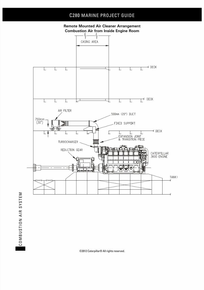
7/23/2019 1.- c280 Epa Tier 2 - Imo II Marine Project Guide
http://slidepdf.com/reader/full/1-c280-epa-tier-2-imo-ii-marine-project-guide 116/222
C28
MARINE PROJECT GUIDE
©2012 Caterpillar® All rights reserved.108
C O M B U S T I O N
A I R S Y S T
E M
Remote Mounted Air Cleaner Arrangement
Combustion Air from Inside Engine Room

7/23/2019 1.- c280 Epa Tier 2 - Imo II Marine Project Guide
http://slidepdf.com/reader/full/1-c280-epa-tier-2-imo-ii-marine-project-guide 117/222
©2012 Caterpillar® All rights reserved. 109
C O
MB U S T I O N
A I R S Y S T E M
Remote Mounted Air Cleaner Arrangement
Combustion Air from Inside Engine Room

7/23/2019 1.- c280 Epa Tier 2 - Imo II Marine Project Guide
http://slidepdf.com/reader/full/1-c280-epa-tier-2-imo-ii-marine-project-guide 118/222
C28
MARINE PROJECT GUIDE
©2012 Caterpillar® All rights reserved.110
E N G I N E R O O M V
E N T I L A
T I O N
Engine Room Ventilation
GeneralAlthough not part of the Caterpillar Scope of Supply for a typical diesel generator
package, the engine room ventilation system is a vital part of a successfulinstallation. The two primary aspects of a properly designed engine roomventilation system addressed in this document are cooling air and combustion air.
• Cooling Air: The flow of air required to carry away the radiated heat of theengine(s) and other engine room machinery.
• Combustion Air: The flow of air required to burn the fuel in the engine(s).
Both of these have a direct impact on an engine’s or packaged unit’sperformance, and must be considered in the design of an engine room ventilationsystem. However, it is important to note that all equipment within the engine roomspace, not only the diesel generator packages, must be given consideration in the
overall ventilation system design process.
Sizing Considerations
Cooling Air
Engine room ventilation air (cooling air) has two basic purposes:
• To provide an environment that permits the machinery and equipment tofunction properly with dependable service life.
• To provide an environment in which personnel can work comfortably.
A small percentage of fuel consumed by an engine is lost to the environment in
the form of heat radiated to the surrounding air. In addition, heat from generatorinefficiencies and exhaust piping can easily equal engine radiated heat. Anyresulting elevated temperatures in the engine room may adversely affectmaintenance, personnel, switchgear, and engine or generator set performance. Theuse of insulated exhaust pipes, silencer, and jacket water pipes will reduce theamount of heat radiated by auxiliary sources.
Radiated heat from the engines and other machinery in the engine room isabsorbed by engine room surfaces. Some of the heat is transferred to atmosphere,but the remaining radiated heat must be carried away by the ventilation system.
A system for exhausting ventilation air from the engine room must be included in
the ventilation system design. The engine(s) will not be able to carry all of theheated ventilation air from the engine room by way of the exhaust piping.
Combustion Air
In many installations, combustion air is drawn from outside of the engine roomvia ductwork, in which case, the combustion air is not a factor in the ventilationsystem design calculations. However, many installations require that combustionair be drawn directly from the engine room. In these installations, combustion airrequirements become a significant ventilation system design parameter. Enginespecific combustion air requirements can be found in the Technical Data section forthe specific engine and rating.

7/23/2019 1.- c280 Epa Tier 2 - Imo II Marine Project Guide
http://slidepdf.com/reader/full/1-c280-epa-tier-2-imo-ii-marine-project-guide 119/222
©2010 Caterpillar® All rights reserved. 111
E N G
I N E R O O M V E N T I L A T I O N
Ventilation Air Flow
Required ventilation air flow depends on the desired engine room air temperatureas well as the cooling air and combustion air requirements outlined above. While itis understood that total engine room ventilation air flow must take all equipmentand machinery into account, the following sections provide a means for estimating
the air flow required for the successful operation of Caterpillar engines andpackages.
In general, changing the air in the engine room every one or two minutes will beadequate, if flow routing is proper.
Provisions should be made by the installer to provide incoming ventilation air of0.1 to 0.2 m3/min (4 to 8 cfm) per installed horsepower. This does not includecombustion air for the engines.
Engine Room TemperatureA properly designed engine room ventilation system will maintain engine room air
temperatures within 8.5 to 12.5°C (15 to 22.5°F) above the ambient airtemperature (ambient air temperature refers to the air temperature surrounding thepower plant, vessel, etc.). Maximum engine room temperatures should not exceed49°C (120°F). If they do, then outside air should be ducted directly to the engineair cleaners. The primary reason for cooling an engine room is to protect variouscomponents from excessive temperatures. Items that require cool air are:
• Electrical and electronic components
• Air cleaner inlets
• Torsional dampers
•
Generators or other driven equipment
• Engine room for the engine operator or service personnel.
In larger multiple engine sites, the normal 8.5 to 12.5°C (15 to 22.5°F)temperature rise guidelines for engine rooms may require unobtainable oruncomfortable air velocities. For these larger sites, a ventilation system that givespriority to the five items listed above and provides a bottom to top air flow can bedesigned for a temperature rise of 17°C (30°F).
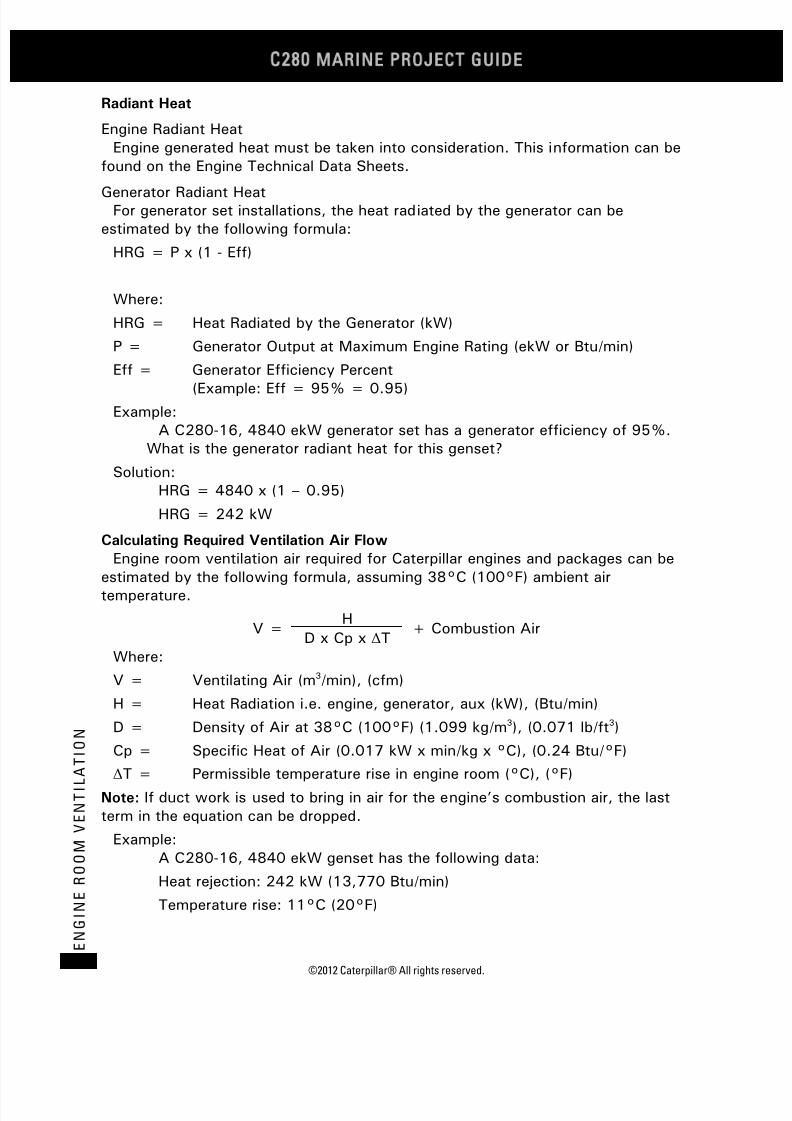
7/23/2019 1.- c280 Epa Tier 2 - Imo II Marine Project Guide
http://slidepdf.com/reader/full/1-c280-epa-tier-2-imo-ii-marine-project-guide 120/222
C28
MARINE PROJECT GUIDE
©2012 Caterpillar® All rights reserved.112
E N G I N E R O O M V
E N T I L A
T I O N
Radiant Heat
Engine Radiant HeatEngine generated heat must be taken into consideration. This information can be
found on the Engine Technical Data Sheets.
Generator Radiant HeatFor generator set installations, the heat radiated by the generator can be
estimated by the following formula:
HRG = P x (1 - Eff)
Where:
HRG = Heat Radiated by the Generator (kW)
P = Generator Output at Maximum Engine Rating (ekW or Btu/min)
Eff = Generator Efficiency Percent
(Example: Eff = 95% = 0.95)
Example:A C280-16, 4840 ekW generator set has a generator efficiency of 95%.
What is the generator radiant heat for this genset?
Solution:HRG = 4840 x (1 – 0.95)
HRG = 242 kW
Calculating Required Ventilation Air Flow
Engine room ventilation air required for Caterpillar engines and packages can be
estimated by the following formula, assuming 38°C (100°F) ambient airtemperature.
V =H
+ Combustion AirD x Cp x ΔT
Where:
V = Ventilating Air (m3/min), (cfm)
H = Heat Radiation i.e. engine, generator, aux (kW), (Btu/min)
D = Density of Air at 38°C (100°F) (1.099 kg/m3), (0.071 lb/ft3)
Cp = Specific Heat of Air (0.017 kW x min/kg x °C), (0.24 Btu/°F)
ΔT = Permissible temperature rise in engine room (°C), (°F)Note: If duct work is used to bring in air for the engine’s combustion air, the lastterm in the equation can be dropped.
Example:A C280-16, 4840 ekW genset has the following data:
Heat rejection: 242 kW (13,770 Btu/min)
Temperature rise: 11°C (20°F)

7/23/2019 1.- c280 Epa Tier 2 - Imo II Marine Project Guide
http://slidepdf.com/reader/full/1-c280-epa-tier-2-imo-ii-marine-project-guide 121/222
©2010 Caterpillar® All rights reserved. 113
E N G
I N E R O O M V E N T I L A T I O N
Solution:The estimated engine room ventilation required for this arrangement:
V =242
= 1178 m3/min1.099 x 0.017 x 11
V =13770
= 40,400 cfm0.071 x 0.24 x 20
Ventilation FansIn modern installations, except for special applications, natural draft ventilation is
too bulky for practical consideration. Adequate quantities of fresh air are bestsupplied by powered (fan-assisted) ventilation systems.
Fan Location
Fans are most effective when they withdraw ventilation air from the engine roomand exhaust the hot air to the atmosphere. However, ideal engine room ventilationsystems will utilize both supply and exhaust fans. This will allow the systemdesigner the maximum amount of control over ventilation air distribution.
Fan Type
Ventilation fans are typically of the vane-axial, tube-axial or propeller type, or thecentrifugal type (squirrel cage blowers). The selection of fan type is usuallydetermined by ventilation air volume and pressure requirements, and also by spacelimitations within the engine room. When mounting exhaust fans in ventilation airdischarge ducts, which are the most effective location, the fan motors should bemounted outside the direct flow of hot ventilating air for longest motor life. Thedesign of centrifugal fans (squirrel cage blowers) is ideal in this regard, but their
size, relative to the vane-axial or tube-axial fans, sometimes puts them at adisadvantage.
Fan Sizing
Fan sizing involves much more than just selecting a fan that will deliver the airflow volume needed to meet the cooling air and combustion air requirementsdetermined earlier in this section. It requires a basic understanding of fanperformance characteristics and ventilation system design parameters.
Similar to a centrifugal pump, a fan operates along a specific fan curve thatrelates a fan’s volume flow rate (m3/min or cfm) to pressure rise (mm H2O or in.H2O) at a constant fan speed. Therefore, fan selection not only requires that thevolume flow rate be known, but also that the ventilation distribution system beknown in order to estimate the system pressure rise. This information allows theoptimum fan to be selected from a set of manufacturers’ fan curves or tables.
Exhaust FansVentilation air exhaust systems should be designed to maintain a slight positive or
negative pressure in the engine room, depending on the specific application.

7/23/2019 1.- c280 Epa Tier 2 - Imo II Marine Project Guide
http://slidepdf.com/reader/full/1-c280-epa-tier-2-imo-ii-marine-project-guide 122/222
C28
MARINE PROJECT GUIDE
©2012 Caterpillar® All rights reserved.114
E N G I N E R O O M V
E N T I L A
T I O N
Generally, maintaining a slight positive pressure in the engine room isrecommended, but should normally not exceed 50 Pa (0.2 in. H2O). This positivepressure accomplishes several things:
• It prevents the ingress of dust and dirt, which is especially beneficial forthose applications involving engines that draw their combustion air from the
engine room.
• It creates an out draft to expel heat and odor from the engine room.
Some applications require that a slight negative pressure be maintained in theengine room, but normally not in excess of 12.7 mm H2O (0.5 in. H2O). The excessexhaust ventilation air accomplishes several things:
• It compensates for the thermal expansion of incoming air.
• It creates an in draft to confine heat and odor to the engine room.
Two Speed Fan Motors
Operation in extreme cold weather may require reducing ventilation airflow toavoid uncomfortably cold working conditions in the engine room. This can be easilydone by providing ventilation fans with two speed (100% and 50% or 67%speeds) motors.
Routing ConsiderationsCorrect ventilation air routing is vital for creating and maintaining the optimum
engine room environment required to properly support the operation of Caterpillarengines and packaged units. Maintaining recommended air temperatures in theengine room is impossible without proper routing of the ventilation air.
Fresh air inlets should be located as far from the sources of heat as practical and
as high as possible; and since heat causes air to rise, it should be exhausted fromthe engine room at the highest point possible, preferably directly over the engine.
Where possible, individual exhaust suction points should be located directly abovethe primary heat sources in order to remove the heat before it has a chance to mixwith engine room air and raise the average temperature. However, it must be notedthat this practice will also require that ventilation supply air be properly distributedaround the primary heat sources.
Avoid ventilation air supply ducts that blow cool air directly toward hot enginecomponents. This mixes the hottest air in the engine room with incoming cool air,raising the temperature of all the air in the engine room, and leaves areas of the
engine room with no appreciable ventilation.For offshore applications, where the potential exists for sea water to be drawn
into the ventilation air supply, the combustion air should be delivered in a mannerthat will preclude any sea water from being ingested by the turbochargers throughthe air intake filters.
These General Routing Principles, while driven by the same basic principles ofheat transfer, will vary with the specific application. This section discusses thegeneral considerations relating to 1 and 2 engine applications, multiple engine (3+)applications, and several special applications.
7/23/2019 1.- c280 Epa Tier 2 - Imo II Marine Project Guide
http://slidepdf.com/reader/full/1-c280-epa-tier-2-imo-ii-marine-project-guide 123/222
©2010 Caterpillar® All rights reserved. 115
E N G
I N E R O O M V E N T I L A T I O N
1 and 2 Engine Applications
These applications will generally require smaller engine rooms, which maysometimes preclude the use of good routing practices.
Recommended ventilation systems for these applications, presented in order ofpreference, are described below:
Ventilation Types 1 and 2 (Preferred Design)
Outside air is brought into the engine room through a system of ducts. See Figure
1. These ducts should be routed between engines, at floor level, and discharge airup at the engines and generators. The most economical method is to use a serviceplatform, built up around the engines, as the top of this duct. See Figure 2.
This requires the service platform to be constructed of solid, nonskid plate ratherthan perforated or expanded grating. The duct outlet will be the clearance betweenthe decking and oilfield base.
Ventilation air exhaust fans should be mounted or ducted at the highest point in
the engine room. They should be directly over heat sources.This system provides the best ventilation with the least amount of air required. In
addition, the upward flow of air around the engine serves as a shield whichminimizes the amount of heat released into the engine room. Air temperature in theexhaust air duct will be higher than engine room air temperature.
Ventilation Type 3 (Alternate Design)
If Ventilation Types 1 or 2 are not feasible, the following method isrecommended; however, it will require approximately 50% more air flow:
Outside air is brought into the engine room as far away as practical from heatsources, utilizing fans or large intake ducts. The air is discharged into the engine
room as low as possible. See Figure 3. Allow air to flow across the engine roomfrom the cool air entry point(s) toward sources of engine heat such as the engine,exposed exhaust components, generators, or other large sources of heat.
Ventilation air exhaust fans should be mounted or ducted at the highest point inthe engine room. Preferably, they should be directly over heat sources.
Engine heat will be dissipated with this system, but a certain amount of heat willstill radiate and heat up all adjacent engine room surfaces.
If the air is not properly routed, it will rise to the ceiling before it gets to theengines.
This system will work only where the air inlets circulate the air between theengines, for 2 engine applications. Air inlets located at the end of the engine roomwill provide adequate ventilation to only the engine closest to the inlet.
Ventilation Type 4 (Alternate Design)
If Ventilation Types 1, 2 or 3 are not feasible, the following method can be used;however, it provides the least efficient ventilation and requires approximately 2.5times the air flow of Ventilation Types 1 and 2:
Outside air is brought into the engine room using supply fans, and dischargedtoward the turbocharger air inlets on the engines. See Figure 4.

7/23/2019 1.- c280 Epa Tier 2 - Imo II Marine Project Guide
http://slidepdf.com/reader/full/1-c280-epa-tier-2-imo-ii-marine-project-guide 124/222
C28
MARINE PROJECT GUIDE
©2012 Caterpillar® All rights reserved.116
E N G I N E R O O M V
E N T I L A
T I O N
Ventilation exhaust fans should be mounted or ducted from the corners of theengine room.
This system mixes the hottest air in the engine room with the incoming cool air,raising the temperature of all air in the engine room. It also interferes with thenatural convection flow of hot air rising to exhaust fans. Engine rooms can be
ventilated this way, but it requires extra large capacity ventilating fans.
Ventilation Type 1
Ventilation Type 2
Figure 1
Figure 2

7/23/2019 1.- c280 Epa Tier 2 - Imo II Marine Project Guide
http://slidepdf.com/reader/full/1-c280-epa-tier-2-imo-ii-marine-project-guide 125/222
©2010 Caterpillar® All rights reserved. 117
E N G
I N E R O O M V E N T I L A T I O N
Ventilation Type 3
Ventilation Type 4
Multiple Engine (3+) Applications
Multiple engine applications, involving three or more engines or packaged units,will generally require larger engine rooms than those needed for 1 and 2 engineapplications.
In general, the recommended ventilation systems outlined for 1 and 2 engine
applications also apply to multiple engine applications. However, there are severaladditional considerations that are specific to multiple engines.
As previously mentioned, the application of normal temperature rise guidelines fordetermining large multiple engine site ventilation requirements will generally resultin extremely large volumes of air. Therefore, the guidelines used for these sites aresignificantly more generous; however, even with the increased temperature riseallowed, the ventilation requirements will be significant. Large multiple engine siteswill generally utilize multiple ventilation fans, often using one or two fans for eachengine. This practice allows for a very simple arrangement requiring minimalductwork.
Figure 3
Figure 4

7/23/2019 1.- c280 Epa Tier 2 - Imo II Marine Project Guide
http://slidepdf.com/reader/full/1-c280-epa-tier-2-imo-ii-marine-project-guide 126/222
C28
MARINE PROJECT GUIDE
©2012 Caterpillar® All rights reserved.118
E N G I N E R O O M V
E N T I L A
T I O N
The use of multiple ventilation fans, either supply or exhaust, will require that airflow between the engines be arranged, either by fan placement or by distributionductwork. Figure 5 and Figure 6 show examples of correct and incorrect air flowpatterns for multiple engine sites.
Correct Air Flow
Incorrect Air Flow
Figure 5
Figure 6

7/23/2019 1.- c280 Epa Tier 2 - Imo II Marine Project Guide
http://slidepdf.com/reader/full/1-c280-epa-tier-2-imo-ii-marine-project-guide 127/222
©2012 Caterpillar® All rights reserved. 119
E X H A U S T S Y S T E M
Exhaust System
GeneralThe C280 engine uses a pulse exhaust manifold system. The front and rear three
cylinders are connected to separate turbine inlets.
Exhaust System Design Considerations
Exhaust Backpressure Limits
The total C280 exhaust backpressure limit is 254 mm H2O (10 in H2O). This levelwas established with an emphasis on low specific fuel consumption and exhaustvalve temperatures. Therefore, to achieve proper performance of the engine, theexhaust backpressures must be kept below this limit.
System backpressure should be measured in a straight length of the exhaust pipeat least 3 to 5 pipe diameters away from the last size transition from the
turbocharger outlet. System backpressure measurement is part of the enginecommissioning.
Turbochargers
For the single turbocharger 6 cylinder engine and the two turbocharger 12cylinder engine, the turbochargers are located at the flywheel end of the engine.The turbocharger exhaust outlet is rectangular with an area equivalent to 311 mm(12 in.) diameter. A cast adapter mounts to each turbocharger to provide a 355mm (14 in.) diameter customer connection point. Optional attachments for theseturbochargers include 355 mm (14 in.) diameter flexible bellows, expansiontransitions from 355 mm (14 in.) to 457 mm (18 in.) diameter, 457 mm (18 in.)
diameter bellows, and exhaust flanges with bolting and mounting hardware.For the single turbocharger 8-cylinder engine and the two turbocharger 16-
cylinder engine, the turbochargers are located at the flywheel end of the engine.The turbocharger exhaust outlet is 355 mm (14 in.) diameter with cast adaptorsmounted to each turbocharger to provide a 457 mm (18 in.) diameter customerconnection point. Optional attachments for these turbochargers include 355 mm(14 in.) diameter flexible bellows, 457 mm (18 in.) diameter bellows, and exhaustflanges with bolting and mounting hardware.
Additionally, there is an optional two turbocharger 16-cylinder engine with theturbochargers mounted opposite the flywheel end of the engine for a front mounted
turbo engine configuration. This engine includes the same cast adaptors andoptions as the previously mentioned rear mounted turbo engine configuration.
The exhaust bellows are intended to compensate for thermal growth andmovement of the engine. The exhaust system structure immediately after theengine exhaust bellows must be a fixed, rigid point. The supplied exhaust bellowswill only handle the engine movement and thermal growth. No additional externalloading is allowed on the turbochargers.
Exhaust Slobber (Extended Periods of Low Load)
Prolonged low load operation should be followed by periodic operation at higherload to burn out exhaust deposits. Low load operation is below 400 kPa bmep (58
7/23/2019 1.- c280 Epa Tier 2 - Imo II Marine Project Guide
http://slidepdf.com/reader/full/1-c280-epa-tier-2-imo-ii-marine-project-guide 128/222
C28
MARINE PROJECT GUIDE
©2012 Caterpillar® All rights reserved.120
E X H A U S T S Y S T E M
psi bmep) (approximately 20% load, depending on rating). The engine should beoperated above 800 kPa bmep (116 psi bmep) (about 40% load, depending onrating) periodically to burn out the exhaust deposits. The amount of additional timedepends upon the engine configuration, water temperature to the aftercooler, inletair temperature to the engine and type of fuel.
Engine Operation at Idle or Low Load Conditions
Absolute Idle (declutched and/or disconnected):
• Maximum of 10 minutes if the engine is going to be stopped – 3 to 5minutes of idling is recommended prior to shutdown.
• Maximum of 4 hours if the engine is to be loaded after idling.
Operation below 10% load on recommended distillate diesel fuels:
• Engine can be run for 100 hours, and then should be taken to a minimumload of 70% for 1 hour; then the engine can be returned to idle at the lowload condition.
Operation above 10% load on recommended distillate diesel fuels:
• No restrictions
Exhaust Piping
A common exhaust system for multiple installations is not acceptable. An exhaustsystem combined with other engines allows operating engines to force exhaustgases into engines not operating. The water vapor condenses in the cold enginesand may cause engine damage. Additionally, soot clogs turbochargers, aftercoolers,and cleaner elements. Valves separating engine's exhaust systems are alsodiscouraged. High temperatures warp valve seats and soot deposit causes leakage.
The exhaust pipe diameter is based on engine output, gas flow, and length ofpipe and number of bends. The maximum gas velocity should not exceed 50 m/s(164 ft/sec) at full load. Sharp bends should be avoided, and where necessary,should have the largest possible radius. The minimum radius should be 1½ pipediameters. The piping should be as short as possible and insulated. The insulationshould be protected by mechanical lagging to keep it intact. All flexible exhaustfittings should be insulated using removable quilted blankets. It is recommended toprovide the system with a valve drain arrangement to prevent rainwater fromentering the engine during prolonged shutdown periods. For testing purposes, theexhaust system must have a test port installed after the turbocharger outlet. Thistest port should be a 10 to 13 mm (0.39 to 0.51 in.) plugged pipe welded to theexhaust piping and of sufficient length to bring it to the outer surface of theinsulated piping.
Exhaust piping must be able to expand and contract. It is required that one fixedpoint be installed directly after the flexible exhaust fitting at the turbochargeroutlet. This will prevent the transmission of forces resulting from weight, thermalexpansion or lateral displacement of the external exhaust piping from acting on theturbocharger.

7/23/2019 1.- c280 Epa Tier 2 - Imo II Marine Project Guide
http://slidepdf.com/reader/full/1-c280-epa-tier-2-imo-ii-marine-project-guide 129/222
©2012 Caterpillar® All rights reserved. 121
E X H A U S T S Y S T E M
Engine Piping ConnectionsFor the single turbocharger 6 cylinder engine and the two turbocharger 12
cylinder engine, the turbocharger exhaust outlet is rectangular with an areaequivalent to 311 mm (12 in.) diameter.
For the single turbocharger 8-cylinder engine and the two turbocharger 16-cylinder engine, the turbocharger exhaust outlet is 355 mm (14 in.) diameter withcast adaptors mounted to each turbocharger to provide a 457 mm (18 in.) diametercustomer connection point.
Exhaust Gas Piping SystemA typical exhaust system arrangement is shown below.

7/23/2019 1.- c280 Epa Tier 2 - Imo II Marine Project Guide
http://slidepdf.com/reader/full/1-c280-epa-tier-2-imo-ii-marine-project-guide 130/222
C28
MARINE PROJECT GUIDE
©2012 Caterpillar® All rights reserved.122
E N G I N E G O V E R N I N G A N
D C O N T R O L S Y S T E M
Engine Governing and Control System
IntroductionThis section and the following section describe the standard Caterpillar GMS or
MMS control and governor arrangement and optional ECP control systems. Thestandard control system offering is a PLC based control and monitoring systemwith a relay based backup safety shutdown system. The system is capable ofcommunicating with the vessel main control system through variouscommunication protocols. The ECP control system options provide a relay basedsystem only and provides no remote communication capabilities.
Generator Engine Governing System
C280
• ADEM III
• Optional Direct Rack (PLC required)
Note: Direct Rack is mutually exclusive with the load sharing module.
Generator Engine Control System
The control system uses single Caterpillar ADEM A3 Electronic Engine ControlModules with Electronic Unit Injection Fuel System.
The following main components are included:
• Rigid wiring harness.
Protection System PLC (MMS / GMS)PLC (programmable logic controller) based system: (Also known as MMS/GMS
system)The PLC based system provides protection, monitoring, and control housed in a
NEMA 4 (IP66) enclosure. All critical shutdowns have both relay and PLC basedprotection. Sensors are factory wired directly to an engine mounted terminal boxfor a ship loose package or an engine only selection. Sensors are wired directly tothe control panel when an accessory module is ordered and is factory packaged;Otherwise control panel is shipped loose for customer mounting. Use of PLCeliminates the need for a separate gauge panel and annunciator panel.
Features
• 254 mm (10.0 in.) color monitor to display all engine parameters and alarm
annunciation. The color monitor has a general overview screen, an exhaustscreen, lube oil screen, cooling screen, air and fuel screen and an auxiliaryscreen. The alarms are annunciated with a time and date stamp.
• Annunciation of all engines shutdowns, alarms and status points.
• Start/prelube control switch, fuel control switch and emergency stop button.
• Selection of local/remote control of engine.
• Selection of idle/rated control of engine.
• Equipped for remote communication.
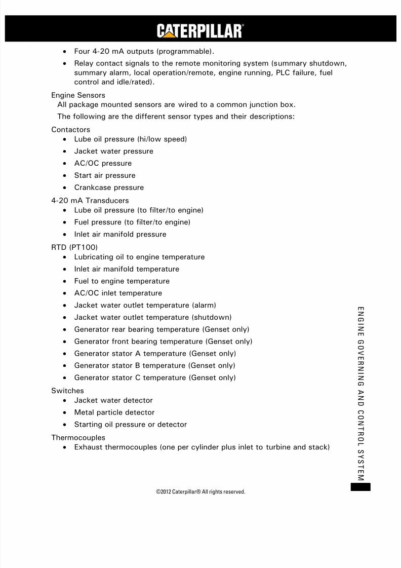
7/23/2019 1.- c280 Epa Tier 2 - Imo II Marine Project Guide
http://slidepdf.com/reader/full/1-c280-epa-tier-2-imo-ii-marine-project-guide 131/222
©2012 Caterpillar® All rights reserved. 123
E N G I N E G O V E R N I N G
A N D C O N T R O L S Y S T E M
• Four 4-20 mA outputs (programmable).
• Relay contact signals to the remote monitoring system (summary shutdown,summary alarm, local operation/remote, engine running, PLC failure, fuelcontrol and idle/rated).
Engine SensorsAll package mounted sensors are wired to a common junction box.
The following are the different sensor types and their descriptions:
Contactors• Lube oil pressure (hi/low speed)
• Jacket water pressure
• AC/OC pressure
• Start air pressure
• Crankcase pressure
4-20 mA Transducers• Lube oil pressure (to filter/to engine)
• Fuel pressure (to filter/to engine)
• Inlet air manifold pressure
RTD (PT100)
• Lubricating oil to engine temperature
• Inlet air manifold temperature
• Fuel to engine temperature
• AC/OC inlet temperature• Jacket water outlet temperature (alarm)
• Jacket water outlet temperature (shutdown)
• Generator rear bearing temperature (Genset only)
• Generator front bearing temperature (Genset only)
• Generator stator A temperature (Genset only)
• Generator stator B temperature (Genset only)
• Generator stator C temperature (Genset only)
Switches• Jacket water detector
• Metal particle detector
• Starting oil pressure or detector
Thermocouples• Exhaust thermocouples (one per cylinder plus inlet to turbine and stack)

7/23/2019 1.- c280 Epa Tier 2 - Imo II Marine Project Guide
http://slidepdf.com/reader/full/1-c280-epa-tier-2-imo-ii-marine-project-guide 132/222
C28
MARINE PROJECT GUIDE
©2012 Caterpillar® All rights reserved.124
E N G I N E G O V E R N I N G A N
D C O N T R O L S Y S T E M
Interfacing
• Engine is factory equipped with the required sensors needed for the PLC.
• Accepts remote signals for starting/interlock, stopping and emergency stop.
• All monitored parameters and status available on DH+ network.
• An Ethernet connection is available by Custom Quote.• MODBUS communication available in optional feature code selection.
Alarms
Pressure:
• Low oil pressure
• High oil filter differential
• Low fuel pressure
• High fuel filter differential
•
High inlet air manifold pressure• Low starting air pressure
• Low jacket water pressure
• Low AC/OC water pressure
• Low raw/sea water pressure (customer supplied contact)
Temperature:• High lube oil temperature
• High inlet air manifold temperature
• High fuel temperature
• High AC/OC inlet temperature
• High jacket water outlet temperature
• High generator rear bearing temperature (Genset only)
• High generator front bearing temperature (Genset only)
• High generator stator A temperature (Genset only)
• High generator stator B temperature (Genset only)
• High generator stator C temperature (Genset only)
• High individual exhaust port temperature
• High turbine inlet temperature
• High exhaust stack temperature
• High exhaust port deviation temperature

7/23/2019 1.- c280 Epa Tier 2 - Imo II Marine Project Guide
http://slidepdf.com/reader/full/1-c280-epa-tier-2-imo-ii-marine-project-guide 133/222
©2012 Caterpillar® All rights reserved. 125
E N G I N E G O V E R N I N G
A N D C O N T R O L S Y S T E M
Other:
• Low battery voltage
• Low oil level
• Jacket water detection
• Low coolant level (Switch supplied with an expansion tank or customersupplied if an expansion tank is not selected).
• Metal particle detection
Shutdowns
Pressure:
• Low oil pressure
• High crankcase pressure
Temperature:• High jacket water temperature
• High lube oil temperature
• High generator bearing temperature (Genset only)
Other:
• Metal particle detection
• Engine overspeed
• Customer shutdown (normally open contact customer supplied)
Programmable InputsThe customer can wire, display and alarm on two customer supplied RTD’s, and
two customer-supplied 4-20 mA (0-10 VDC) sensors, three discrete alarms, andthree discrete shutdowns.
GaugesIn addition to the 10 inch color monitor that displays all engine parameters, there
are also three engine mounted gauges and three control panel gauges. The threeengine mounted gauges are fuel pressure, lube oil pressure and inlet air restriction.The three control panel gauges include an engine hour meter, digital tachometerand a starting air pressure gauge.
LightsFour lights are included on the control panel for displaying prelube status,
summary alarm, summary shutdown and PLC failure.Construction
Enclosure – NEMA 4 (IP66).

7/23/2019 1.- c280 Epa Tier 2 - Imo II Marine Project Guide
http://slidepdf.com/reader/full/1-c280-epa-tier-2-imo-ii-marine-project-guide 134/222
C28
MARINE PROJECT GUIDE
©2012 Caterpillar® All rights reserved.126
E N G I N E G O V E R N I N G A N
D C O N T R O L S Y S T E M
PLC Monitoring System Options
AC/OC/JW/Air Start/Upgrade/VeeUpgrades AC/OC, JW and starting air pressure from contactors to 4-20mA
transducers.
Raw/Sea Water Pressure TransducerAdds a raw/sea water transducer.
MODBUS CommunicationsAdds a MODBUS card to panel.
Beacon and HornShipped loose. Provides a beacon and horn assembly to panel.
Single Engine REM Display MonitorPLC display – Monitor. A remote 254 mm (10 inch) color monitor to display all
engine parameters and annunciation. The monitor is identical to the one in the face
of the standard PLC panel. The monitor is shipped loose.Cabinet Cooler
Customer mounted air powered cabinet cooler. Includes cooler, filter, solenoidand thermostat. It requires 80-110 psig (552-690 kPa) clean, dry air.Recommended for applications where ambient air temperature exceeds 50°C(122°F), but does not exceed 60°C (140°F).
Power Monitoring/Gen SetA multifunction digital power monitor is shipped loose for installation within the
switchgear or generator control panel. The power monitor communicates with thePLC and displays parameters such as voltage, current, kW, kVAR, pf, frequency,
kW hours and kVAR hours on the GMS monitor.

7/23/2019 1.- c280 Epa Tier 2 - Imo II Marine Project Guide
http://slidepdf.com/reader/full/1-c280-epa-tier-2-imo-ii-marine-project-guide 135/222
©2012 Caterpillar® All rights reserved. 127
E N G I N E G O V E R N I N G
A N D C O N T R O L S Y S T E M
Protection System ECP (Relay Based)The Engine Control Panel (ECP) provides protection and control for a single diesel
engine utilizing contactors and relay based logic housed in a NEMA 4 (IP66)enclosure. If factory wired, the contactors are wired to an engine mounted terminalbox. The ECP's shutdown and alarm system has electronic detection of engineoverspeed which will disable fuel injection. The ECP also has electrical detection forother shutdown or alarm faults. The air inlet shutoff supply safety device isconfigured for energized to shutoff operation (ETS logic). Includes Marine Societyapproved contactors and drip-proof junction box (NEMA 4 or IP66).
Features
• Local prelube control of the engine
• Start/stop control of the engine including emergency stop
• Selection of local/remote control of the engine
• Automatic second ECM backup.
Dry Contacts Available for Customer Use24 VDC alarm and shutdown signals for use with customer supplied annunciator
when Caterpillar annunciator option is not selected.
Gauges• The ECP panel has individual exhaust port monitoring (cylinder
thermocouples)
• Digital tachometer
• Pyrometer
•
Engine hour meter.Lights
• The ECP has a light for displaying engine prelube pressure available.
• The ECP has an option to have an individual light for each alarm when theannunciator option is ordered.
ECP Minimum Protection System (Accessory Module Mounted)
The minimum protection system has the features and functions listed above withthe following protection:
Shutdowns
•
Electrical overspeed• Low oil pressure (low and high rpm)
• High crankcase pressure
• Metal particle detector.
Alarms
• Low oil pressure (low and high speed)
• Loss of jacket water detection
• High oil temperature

7/23/2019 1.- c280 Epa Tier 2 - Imo II Marine Project Guide
http://slidepdf.com/reader/full/1-c280-epa-tier-2-imo-ii-marine-project-guide 136/222
C28
MARINE PROJECT GUIDE
©2012 Caterpillar® All rights reserved.128
E N G I N E G O V E R N I N G A N
D C O N T R O L S Y S T E M
• High jacket water temperature
• High inlet air manifold temperature
• High exhaust manifold temperature
• Metal particle detector
• Low oil level
• Low coolant level
• Includes engine mounted terminal box.
ECP Complete Protection System (Accessory Module Mounted)
The Complete Protection System has the features and functions of the MinimumProtection System and the following additional protection.
Shutdowns• Loss of jacket water detection
• High oil temperature
• High jacket water temperature.
Alarms
• High fuel temperature
• Low starting air pressure
• Includes engine mounted terminal box.
ECP Maximum Protection System (Accessory module mounted)
The maximum protection system has the features and functions of the MinimumProtection System, the Complete Protection System, and the following additional
protection.Alarms
• Low fuel pressure
• Low jacket water pressure
• Low AC/OC pressure.
• Includes engine mounted terminal box.
Other Optional Equipment (Not Control System Dependant)
Turbocharger Speed Sensor
• Provides two speed sensors, one for each turbocharger, so turbocharger
speed may be monitored.
Cylinder Pressure Relief Valve• Includes sixteen relief valves
• Meets major Marine Society requirements
• Engine mounted in cylinder heads
• Automatic combustion chamber pressure relief at Marine Society specifiedover-pressure level.

7/23/2019 1.- c280 Epa Tier 2 - Imo II Marine Project Guide
http://slidepdf.com/reader/full/1-c280-epa-tier-2-imo-ii-marine-project-guide 137/222
©2012 Caterpillar® All rights reserved. 129
E N G I N E G O V E R N I N G
A N D C O N T R O L S Y S T E M
Mechanical Cylinder Pressure Gauge Valve
• Includes sixteen valves
• Engine mounted on cylinder heads
• Accepts mechanical cylinder pressure gauge (not included)
• Manual compression release capability when gauge is not installed• Software thermal shielding is included.
Oil Mist Detector
• Installed on side opposite of service side on rear mounted turboconfigurations
• System required by marine societies for “Alarm and Safety Requirements forUnmanned Machinery Space (UMS)” under the following conditions:
o For DNV: An engine rating greater than or equal to 2250 kW or an enginebore size greater than 200mm.
o For ABS, BV, GL, LRS, RINA: An engine rating greater than or equal to2250 kW or an engine bore size greater than 300mm.
Oil Mist Detector Drain Group• Provides oil drain for use with oil mist detector.
Protection System Components
Fuel Temperature Sensor:
• Provides fuel temperature sensor group.
VTC Air Restrict:
• Provides air restriction instrument panel lines for VTC turbocharger.
Magnetic Speed Pickup Bracket:• Bracket provides four holes for the installation of additional magnetic
pickups. Does not include magnetic pickups.
Other Optional Equipment (Main Components)
• Integral Sump Base Assembly
• Vertically Restrained Vibration Isolators for Packaged Diesel Generator Set
• Torsional Coupling
• MCS Engine Certificate
• GL Approved IMO Certificate
• Engine Lifting Eyes (Shipped Loose)
• Accessory Module
• High Inertia Flywheel with Guard
• Damper with Guard
• Electric Barring Device
• Shrink Wrap and Tarpaulin Protection for Transportation and Storage

7/23/2019 1.- c280 Epa Tier 2 - Imo II Marine Project Guide
http://slidepdf.com/reader/full/1-c280-epa-tier-2-imo-ii-marine-project-guide 138/222
C28
MARINE PROJECT GUIDE
©2012 Caterpillar® All rights reserved.130
E N G I N E G O V E R N I N G A N
D C O N T R O L S Y S T E M
Other Optional Equipment
• Isolator Weld Plates for Connection of Vibration Isolators to CustomerFoundation
Optional Marine Safety Requirements
• Spray Shielding
Optional Spare Part Kits
Intake and Air System
• Air/Exhaust Common
• Exhaust Bellows Kit
• Turbo Kit
Basic Engine
• Basic Engine Kit
• Piston Assembly Kit
• Cuffed Liner Kit
• Bearing Spare parts Kit
• Rod Assembly Kit
Cylinder Head
• Head Kit – Common
• Gasket (Cuffed Liner)
Fuel System
• Fuel Kit – Common
• Injector Kit – Distillate FuelCooling System
• Cooling System Kit – Common
Instrumentation
• Instrument Kit – Distillate Fuel
Cylinder Valve Kit
• Valve Kit – Distillate Fuel
Optional Engine Testing
• Turbocharger and Crankshaft Work Certificates
• Torsional Vibration Analysis of Generator Set
• Customer Witness Test
• Marine Society Certification Witness Test
Optional Service Tools/Shipping Protection/Factory Support
• Factory Commissioning
• Specialized Tooling Group
• Turbocharger Tool Group
• Cylinder Head Repair Tool Group

7/23/2019 1.- c280 Epa Tier 2 - Imo II Marine Project Guide
http://slidepdf.com/reader/full/1-c280-epa-tier-2-imo-ii-marine-project-guide 139/222
©2012 Caterpillar® All rights reserved. 131
E N G I N E G O V E R N I N G
A N D C O N T R O L S Y S T E M
• Protection System Calibrator
• Oil Mist Detector Tool Kit
• Storage Preservation
Optional Literature
• Installation Drawings• Additional Literature Set
• Additional Parts Book – CD
• Additional Service Manual
• Additional Technical Manual
• Paper Parts Book - English
7/23/2019 1.- c280 Epa Tier 2 - Imo II Marine Project Guide
http://slidepdf.com/reader/full/1-c280-epa-tier-2-imo-ii-marine-project-guide 140/222
C28
MARINE PROJECT GUIDE
©2012 Caterpillar® All rights reserved.132
E N G I N E M O N I T O R I N G A
N D S H U T D O W N
Engine Monitoring and Shutdown
Engine ShutdownThe C280 engine is installed with shutdown protection for overspeed, low
lubrication oil pressure, high crankcase pressure, high jacket water temperature,and Metal Particle Detection. High oil mist level alarm and/or shutdown areavailable as an option to satisfy marine societies which typically require this featureon engines above 2250 bkW. In addition, the engine can be shut down through theelectrical control system via emergency shutdown buttons installed as required bythe Marine Classification Society on the bridge and the engine control panel. Forthe shutdowns, the engine is stopped via the shutdown solenoid in the governor.However in case of an overspeed or activated emergency stop button, the enginewill be stopped by an emergency air shutoff system. Both of these measures aretaken as a precaution and to fulfill society requirements.
The engine safety system is operationally independent from the monitoringsystem. That means the engine will shut down for the safety functions, highcrankcase pressure, overspeed and low lubrication pressure even when the PLC isnot operational.
Engine MonitoringEngine monitoring switches and analog sensors (4-20 mA transmitters, RTD’s,
switches, and thermocouples) can vary from one installation to the next.
Pressure Sensors
The engine is installed with a sensor package in accordance with the sensor listenclosed. The pressure sensors are generally mounted on a common panel on
either the front or side of the engine.
Temperature Sensors
The exhaust temperature sensors are thermocouples and the remaining sensorsare RTD's (PT100).
Engine Control Panel
The Engine Control Panel contains the PLC, start / stop logic and man-machineinterface (MMI) touch screen for displaying the operating parameters. The operatoris able to view engine parameters from different screens for each system (exhaust,water, and air) on the engine. The various screens are called to view by buttons
located at the bottom of each screen. All the engine parameters are furtheravailable to the vessel control system via P/C communications.
The monitoring and alarm functions listed in the instrumentation list overleaf aretypical for a C280 Marine engine supply, Marine Classification Society withnotation: Unmanned Machinery Space (UMS).
7/23/2019 1.- c280 Epa Tier 2 - Imo II Marine Project Guide
http://slidepdf.com/reader/full/1-c280-epa-tier-2-imo-ii-marine-project-guide 141/222
©2012 Caterpillar® All rights reserved. 133
E N G I N E M O U N T I N G A N
D F O U N D A T I O N
D E S I G N
Engine Mounting and Foundation Design
Propulsion Engine Mounting and FoundationThis section discusses propulsion engine and reduction gear foundations and their
relationship to ship framing.Exact analytical methods cannot always be used to design engine foundations.
The design is also influenced by several factors, including previous successfulinstallations, the designer's experience, and the basic dimensions of the specificengine being installed. Refer to this guide for specific information on C280 Engineweights and dimensions.
The engine foundation must resist vertical, horizontal and fore-and-aft deflection.It should also be integrated into the reduction gear foundation to connect theoverall structure to the ship's inner bottom structure. In this manner, the thrustfrom the propeller, and the dynamic forces from the main engine and reduction gear
are evenly distributed over a large area of the inner bottom structure. If the enginefoundation has too little resistance against deflection, it may show up during thealignment of the engines as the mount depressions may be influenced by thecombination of foundation deflection and engine forces, and may be out oftolerance.
The main engine foundation must have sufficient rigidity to transmit static anddynamic forces from the main engine into the foundation.
The girder and faceplate must:
• increase bending inertia of the structure
• facilitate chock installation
• provide a "work shelf" for servicing the side of the engine
• permit installation of side blocks and collision chocks
The main engine and reduction gear foundation must also be designed to absorbthe loads from:
• ship's vibration
• propeller thrust
• thrust and torque of the engine
• ship’s motion at sea
• thermal, static and dynamic effects
• crash reversal
Because the loads originate from sources other than the engine, the foundationsections should be uninterrupted and have adequate section strength.
To avoid natural frequency resonance between engine and hull, the engine's 1stand 2nd order free forces and moments must be taken into account whendesigning the mounting structure. The ship builder must ensure that resonancebetween torque excitation and the natural transverse hull frequencies does not

7/23/2019 1.- c280 Epa Tier 2 - Imo II Marine Project Guide
http://slidepdf.com/reader/full/1-c280-epa-tier-2-imo-ii-marine-project-guide 142/222
C28
MARINE PROJECT GUIDE
©2012 Caterpillar® All rights reserved.134
E N G I N E M O U N T I N G A N D F O U N D A T I O N
D E S I G N
occur. Caterpillar will supply engine 1st and 2nd order free forces and moments,upon request.
The engine foundation must have sufficient rigidity to minimize shafting andcoupling deformation between the engine and gear.
C280 Engine Related Frequencies
Excitation Frequency Cause of Excitation Design of Component's
Natural Frequencies
½ order =½ x engine speed
(Correctable) misfiring ofone or more cylinders
Stay Above
1st order =1 x engine speed
Unbalance, misalignment,crankcase overfill
(Correctable)Stay Above
1½ order =
1.5 x engine speed
Normal cylinder combustion
(NOT Correctable)
Avoid: side to side and roll
modes excited by this order2nd order =2 x engine speed
Normal cylinder combustion(NOT Correctable)
Avoid: side to side and rollmodes excited by this order
3rd order =3 x engine speed
Firing frequency for a six(6) cylinder engine or one
bank of a twelve (12)cylinder engine (NOT
Correctable)
Avoid: side to side and rollmodes excited by this order
4th order =
4 x engine speed
Firing frequency for aneight (8) cylinder engine orone bank of a sixteen (16)
cylinder engine (NOTCorrectable)
Avoid: side to side and roll
modes excited by this order
6th order =6 x engine speed
Firing frequency for a six(6) cylinder engine or one
bank of a twelve (12)cylinder engine (NOT
Correctable)
Avoid: side to side and rollmodes excited by this order
8th order =8 x engine speed
Firing frequency for aneight (8) cylinder engine orone bank of a sixteen (16)
cylinder engine (NOTCorrectable)
Avoid: side to side and rollmodes excited by this order
The engine speed varies from 350 rpm for low idle to 1000 rpm for rated speed.

7/23/2019 1.- c280 Epa Tier 2 - Imo II Marine Project Guide
http://slidepdf.com/reader/full/1-c280-epa-tier-2-imo-ii-marine-project-guide 143/222
©2012 Caterpillar® All rights reserved. 135
E N G I N E M O U N T I N G A N
D F O U N D A T I O N
D E S I G N
Auxiliary Engine/Package Mounting and FoundationThis section describes packaged generator set foundations and their relationship
to platform framing.
Exact analytical methods cannot always be used to design foundations. The
design is also influenced by several factors, including previous successfulinstallations, the designer's experience, and the basic dimensions of the specificpackage being installed.
C280 packaged generator set weights can vary from 38,900 kg (86,000 lb) for a6-cylinder, low voltage package with air cooling (excluding radiator weight) up to95,500 kg (210,000 lb) for a 16-cylinder, high voltage package including a plate-type heat exchanger cooling system and generator forced lubrication module.
The generator set foundation must resist vertical, horizontal and fore-and-aftdeflection. If the engine foundation has too little resistance against deflection, itmay show up during the alignment of the engines as the mount depressions may
be influenced by the combination of foundation deflection and engine forces, andmay be out of tolerance.
The generator set foundation must have sufficient rigidity to transmit static anddynamic forces from the package into the foundation.
Mounting
C280 packaged generator sets are furnished on Caterpillar designed rigid bases inorder to maintain alignment between engine, generator and other engine drivenequipment, and must be mounted on spring isolators unless hard mounting hasbeen approved by Caterpillar.
General
All mounting systems must have provisions for alignment retention, collisionstops and engine thermal growth.
Generators
General
Caterpillar C280 Marine Generator Sets (Auxiliary and Diesel Electric Propulsion(DEP)), are packaged with free-standing two-bearing generators, matched to theengine output to provide the customer maximum electrical output to meet theirrequirements, as well as marine classification requirements for the application.Generator specifications and generator testing requirements will need to be
reviewed during the pre-sale phase of the project and established prior to orderplacement. Options to be considered should include sub-transient reactance neededto meet transient responses required and type of current transformers to bemounted and supplied for the project.
For generators supplied by others, generator manufacturer is responsible forproviding any forced lubrication system that may be required for their generator tomeet tilt requirements.
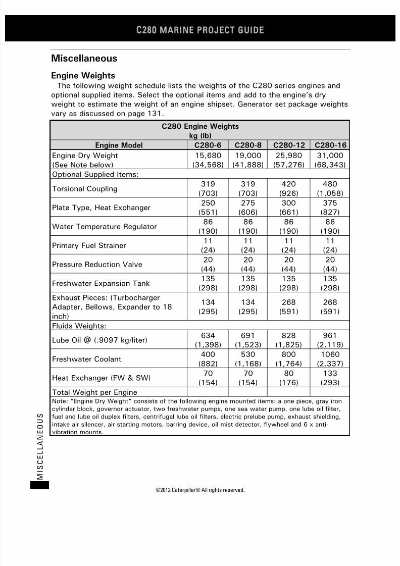
7/23/2019 1.- c280 Epa Tier 2 - Imo II Marine Project Guide
http://slidepdf.com/reader/full/1-c280-epa-tier-2-imo-ii-marine-project-guide 144/222
C28
MARINE PROJECT GUIDE
©2012 Caterpillar® All rights reserved.136
M I S C E L L A N E O U S
Miscellaneous
Engine WeightsThe following weight schedule lists the weights of the C280 series engines and
optional supplied items. Select the optional items and add to the engine’s dryweight to estimate the weight of an engine shipset. Generator set package weightsvary as discussed on page 131.
C280 Engine Weights
kg (lb)
Engine Model C280-6 C280-8 C280-12 C280-16
Engine Dry Weight(See Note below)
15,680(34,568)
19,000(41,888)
25,980(57,276)
31,000(68,343)
Optional Supplied Items:
Torsional Coupling319
(703)
319
(703)
420
(926)
480
(1,058)Plate Type, Heat Exchanger
250(551)
275(606)
300(661)
375(827)
Water Temperature Regulator86
(190)86
(190)86
(190)86
(190)
Primary Fuel Strainer11(24)
11(24)
11(24)
11(24)
Pressure Reduction Valve20(44)
20(44)
20(44)
20(44)
Freshwater Expansion Tank135
(298)135(298)
135(298)
135(298)
Exhaust Pieces: (TurbochargerAdapter, Bellows, Expander to 18inch)
134(295)
134(295)
268(591)
268(591)
Fluids Weights:
Lube Oil @ (.9097 kg/liter)634
(1,398)691
(1,523)828
(1,825)961
(2,119)
Freshwater Coolant400
(882)530
(1,168)800
(1,764)1060
(2,337)
Heat Exchanger (FW & SW)70
(154)70
(154)80
(176)133(293)
Total Weight per EngineNote: “Engine Dry Weight” consists of the following engine mounted items: a one piece, gray ironcylinder block, governor actuator, two freshwater pumps, one sea water pump, one lube oil filter,fuel and lube oil duplex filters, centrifugal lube oil filters, electric prelube pump, exhaust shielding,intake air silencer, air starting motors, barring device, oil mist detector, flywheel and 6 x anti-vibration mounts.
7/23/2019 1.- c280 Epa Tier 2 - Imo II Marine Project Guide
http://slidepdf.com/reader/full/1-c280-epa-tier-2-imo-ii-marine-project-guide 145/222
©2012 Caterpillar® All rights reserved. 137
MI S C E L L A N E O U S
C280 Genset Witness Test DescriptionCaterpillar C280 engines have an option for Witness Testing to be conducted in
the Lafayette Package test cells. No customers or dealer personnel are allowed inthe test cell while the engines are running, and no customer instrumentation maybe connected to the engines, packages, or test cell data acquisition and reporting
systems.
Standard testing includes a load test, transient response test, and vibration test,described as follows:
1. The load test uses 0.8 PF unless otherwise noted, and is recorded at 30 minuteintervals.
• 30 minutes @ 50% rated load
• 30 minutes @ 75% rated load
• 120 minutes @ 100% rated load
• 60 minutes @ 110% rated load, 1.0 PF
The cylinder and exhaust temperatures are manually recorded. All otherdata is recorded electronically and printed by computer.
2. The transient response test is performed at 0.8 PF with load stepping from 0%to 100% ekW, with pre-determined intervals depending on engine frequency,then back to 0%, with examples as follows:
• For 900 rpm (60 Hz) C280-16 or 3616 engines:
o 0% - 1700 ekW - 2880 ekW - 3840 ekW - 100% - 0%
• For 1000 rpm (50 Hz) C280-16 or 3616 engines:
o
0% - 1900 ekW - 3210 ekW – 4275 ekW - 100% - 0%3. The vibration test is taken at 0% and 100% load, and printed by computer. This
is a 14-point, 1-dimensional test around the operating genset package to ensureno unusual vibration is occurring on the as-built configuration.
The standard testing also includes the following data as obtained through thedata acquisition system.
Performance Data:
• rpm
• Real Power (ekW)
• Reactive Power (kVAR)• Power Factor
• Frequency
• Fuel Rate (g/min)
• Specific Fuel Consumption(g/min)
Electrical data:
• Voltage A-B
• Voltage B-C
• Voltage C-A
• Average Voltage
• Current Phase A• Current Phase B
• Current Phase C
• Average Current
Pressures (kPa):
• JW Pump Inlet
• JW Pump Outlet
• AC Outlet
7/23/2019 1.- c280 Epa Tier 2 - Imo II Marine Project Guide
http://slidepdf.com/reader/full/1-c280-epa-tier-2-imo-ii-marine-project-guide 146/222
C28
MARINE PROJECT GUIDE
©2012 Caterpillar® All rights reserved.138
M I S C E L L A N E O U S
• Engine Fuel
• Supply Fuel
• Oil
• Boost
• AC/OC Pump In
• AC/OC Pump Out
Generator RTD:
• Stator Phase A
• Stator Phase B
• Stator Phase C
• Front Bearing
• Rear Bearing
Temperatures (Deg C):• JW Inlet
• JW Outlet
• Oil
• Inlet Manifold
• AC Outlet
• AC/OC In
• AC/OC Out
•
Inlet Fuel• Inlet Air
• Turbocharger Outlet
General Information:
• Customer Name
• Test Date
• ESO Number
Engine Data:• Engine Serial Number
• Engine Arrangement
• E Model
• Engine
• Engine Setting (bkW, rpm)
• OT or 2T
Generator Data:
•
Generator Serial Number• Generator Arrangement
• Volts/Phase/Hertz
• ekW
• ekVA
• Power Factor
Test Operation Data:
• Test Cell (East or West)
• Test Cell Operator
Test Conditions:
• Barometer (kPa)
• Dew Point (deg C)
• Fuel Density (degree API)
Lastly, the following temperatures are recorded during load testing at 50%, 75%,100% (3 separate recordings at this load), and 110% (2 separate recordings at this
load) power:• Exhaust Manifold (Left)
• Exhaust Manifold (Right)
• Cylinders 1 through 16 individually, or as a function of total cylinder count(6, 8, or 12)

7/23/2019 1.- c280 Epa Tier 2 - Imo II Marine Project Guide
http://slidepdf.com/reader/full/1-c280-epa-tier-2-imo-ii-marine-project-guide 147/222
©2012 Caterpillar® All rights reserved. 139
MI S C E L L A N E O U S
Maintenance Interval ScheduleEnsure that all safety information, warnings, and instructions are read and
understood before any operation or any maintenance procedures are performed.
The user is responsible for the performance of maintenance, including all
adjustments, the use of proper lubricants, fluids, filters, and the replacement ofcomponents due to normal wear and aging. Failure to adhere to propermaintenance intervals and procedures may result in diminished performance of theproduct and/or accelerated wear of components.
Use mileage, fuel consumption, service hours, or calendar time, whichever occursfirst, in order to determine the maintenance intervals. Products that operate insevere operating conditions may require more frequent maintenance.
Every Service Hour
o Trend Data - Record
Daily
o Air Starting Motor Lubricator Oil Level - Check
o Air Tank Moisture and Sediment - Drain
o Cooling System Coolant Level - Check
o Driven Equipment – Inspect/Replace/Lubricate
o Engine Air Cleaner Service Indicator - Inspect
o Engine Air Precleaner - Clean
o Engine Oil Level - Check
o Fuel System Primary Filter/Water Separator - Drain
o Fuel Tank Water and Sediment - Draino Instrument Panel – Inspect
o Walk-Around Inspection
Every Week
o Jacket Water Heater - Check
Every 250 Service Hours
o Cooling System Coolant Sample (Level 1) – Obtain
o Cooling System Supplemental Coolant Additive (SCA) – Test/Add
Every 250 Service Hours or 6 Weekso Air Shutoff – Test
o Engine Oil Sample – Obtain
o Oil Mist Detector - Check
Every 500 Service Hours or 3 Months
o Engine Mounts – Inspect
o Engine Protective Devices - Check

7/23/2019 1.- c280 Epa Tier 2 - Imo II Marine Project Guide
http://slidepdf.com/reader/full/1-c280-epa-tier-2-imo-ii-marine-project-guide 148/222
C28
MARINE PROJECT GUIDE
©2012 Caterpillar® All rights reserved.140
M I S C E L L A N E O U S
Initial 1000 Service Hours or 6 Months
o Engine Valve Bridge, Lash, and Injector Fuel Timing – Check/Adjust
o Engine Valve Rotators - Inspect
Every 1000 Service Hours or 6 Months
o Barring Device – Lubricateo Cooling System Coolant Sample (Level 2) – Obtain
o Engine Mounts – Check
o Engine Oil Filter – Change
o Exhaust Piping – Inspect
o Fuel System Primary Filter/Water Separator Element – Replace
o Fuel system Secondary Filter – Replace
o Prelube Pump – Lubricate
o Speed Sensor – Clean/Inspect
Every 2000 Service Hours
o Air Starting Motor Lubricator Bowl - Clean
Every 2000 Service Hours or 1 Year
o Aftercooler Condensation – Drain
o Engine Valve Bridge, Lash, and Injector Fuel Timing – Check/Adjust
o Engine Valve Rotators – Inspect
o Oil Mist Detector – Clean/Replace
Every 4000 Service Hours or 1 Year
o Aftercooler Core – Clean/Testo Starting Motor – Inspect
o Water Temperature Regulator - Replace
Every 8000 Service Hours or 1 Year
o Engine Protection Devices - Calibrate

7/23/2019 1.- c280 Epa Tier 2 - Imo II Marine Project Guide
http://slidepdf.com/reader/full/1-c280-epa-tier-2-imo-ii-marine-project-guide 149/222
©2012 Caterpillar® All rights reserved. 141
MI S C E L L A N E O U S
Every 8000 Service Hours or 3 Years
o Camshaft Roller Followers – Inspect
o Cooling System Coolant (DEAC) – Change
o Cooling System Coolant Extender (ELC) – Add
o Crankshaft Vibration Damper – Inspecto Driven Equipment – Check
o Engine Oil Temperature Regulator – Replace
o Exhaust Shields – Inspect
o Turbocharger – Inspect
o Water Pump - Inspect
Between 16,000 and 24,000 Service Hours
o Top End Overhaul
Every 16,000 Service Hours or 6 Yearso Cooling System Coolant (ELC) - Change
Between 36,000 and 44,000 Service Hours
o Major Overhaul
7/23/2019 1.- c280 Epa Tier 2 - Imo II Marine Project Guide
http://slidepdf.com/reader/full/1-c280-epa-tier-2-imo-ii-marine-project-guide 150/222
C28
MARINE PROJECT GUIDE
©2012 Caterpillar® All rights reserved.142
M I S C E L L A N E O U S
Storage Preservation SpecificationThis specification describes methods and materials used to provide for the
preservation of engines as defined in Caterpillar Document No. 1E2566, Processing– Engine Preservation. These procedures are intended for all C280 engines.
Preservation Procedures
1E2566L Processing (After Assembly and Test)
• All parts should be prepared and painted according to 1E2001.
• Fill Engine Jacket Water (EJW) system with a solution of 20% VCI 379 and80% water or equivalent solution. A regulator bypass line must be used to allowfilling on both sides of the regulator. Vent and EJW system at the highest pointpossible to assure complete filling.
• For engines with Separate Circuit Aftercooler (SCAC) systems fill the SCACsystem with a solution of 20% VCI 379 and water or equivalent solution. Ventthe SCAC system at the highest point possible to assure complete filling.
• Drain the VCI solution from the EJW system at multiple locations to assurecomplete drainage. (EJW pump, 10° block face cover, oil cooler, etc.)
• Drain the VCI solution from engines with SCAC system at the SCAC waterpump. Close all EJW and SCAS system openings with the parts specified onengineering drawings.
• Spray a mixture of 50% 1 E2359 VCI oil and 50% engine oil into the air intakeor turbocharger inlet. Minimum application rate is 7.5 mL/L of enginedisplacement. Install covers specified on engineering drawing to seal in VCIvapors.
• Spray a mixture of 50% 1E2359 VCI oil and 50% engine oil into the exhaustopening. Minimum application rate is 7.5 mL/L of engine displacement. Installcovers specified on engineering drawing to seal in VCI vapors.
• Fill oiler reservoir for air starter with a mixture of 50% 1 E2359 VCI Oil and50% engine oil.
• All other lubricating oil compartments are to be protected by 1E2359 VCI Oil byone of the following methods:
• Run the engine for the final 3 to 5 minutes with oil which has 3 to 4% of 1E2359 VCI Oil by volume. This oil may be drained or left in the engine. Seal VCIvapors in the engine with covers specified on engineering drawings.
• The vapor phase of the VCI oil evaporates rapidly at engine operatingconditions. If further instructions are needed, consult with the EngineeringMaterials Section of the Engine Division.
• Install a mixture of 50% 1 E2359 VCI Oil and 50% engine oil in the lubricatingoil compartments at the rate of 1 part of mixture per 15 parts of compartmentcapacity at full level. Seal VCI vapors in the engine with covers specified onengineering drawings.

7/23/2019 1.- c280 Epa Tier 2 - Imo II Marine Project Guide
http://slidepdf.com/reader/full/1-c280-epa-tier-2-imo-ii-marine-project-guide 151/222
©2012 Caterpillar® All rights reserved. 143
MI S C E L L A N E O U S
• This method can be used with an empty or partially filled lubricating oilcompartment. If the compartment is already full, it may be necessary to drainsome lubricant to facilitate the addition of the mixture.
• Install 30 mL of a mixture of 50% 1 E2359 VCI and 50% engine oil in eachcylinder and rotate crankshaft two turns. Tighten all fittings to the correct
torque. Check the fuel system to verify that it is full of fuel. Install coversspecified on engineering drawing to seal in fuel and vapors.
• Spray a thin film of mixture of 50% 1 E2359 VCI Oil and 50% engine oil on theflywheel, ring gear, and starter pinion. To seal in vapors, install the coversspecified on engineering drawings for the flywheel housing and starter opening,and the plugs specified for through holes.
• Apply a heavy coating of 1 E0325 Grease to the bearing surfaces of all pin and joint connections and other non-painted surfaces.
• All tapped holes must be protected by painting or by applying MS2254 Coating
or equivalent. Tapped holes shall be free of water before applying MS2254Coating or equivalent and sealed with a tightly fit plastic plug or equivalent.

7/23/2019 1.- c280 Epa Tier 2 - Imo II Marine Project Guide
http://slidepdf.com/reader/full/1-c280-epa-tier-2-imo-ii-marine-project-guide 152/222
C28
MARINE PROJECT GUIDE
©2012 Caterpillar® All rights reserved.144
G E N E R A L A R R A N G E M E N
T D R A W I N G S
General Arrangement Drawings
C280-Diesel Engine General Arrangement DrawingsNote: These drawings are based on the Rear Mounted Turbocharger Option.
C280-6 Engine Only
Right Side 2777716A
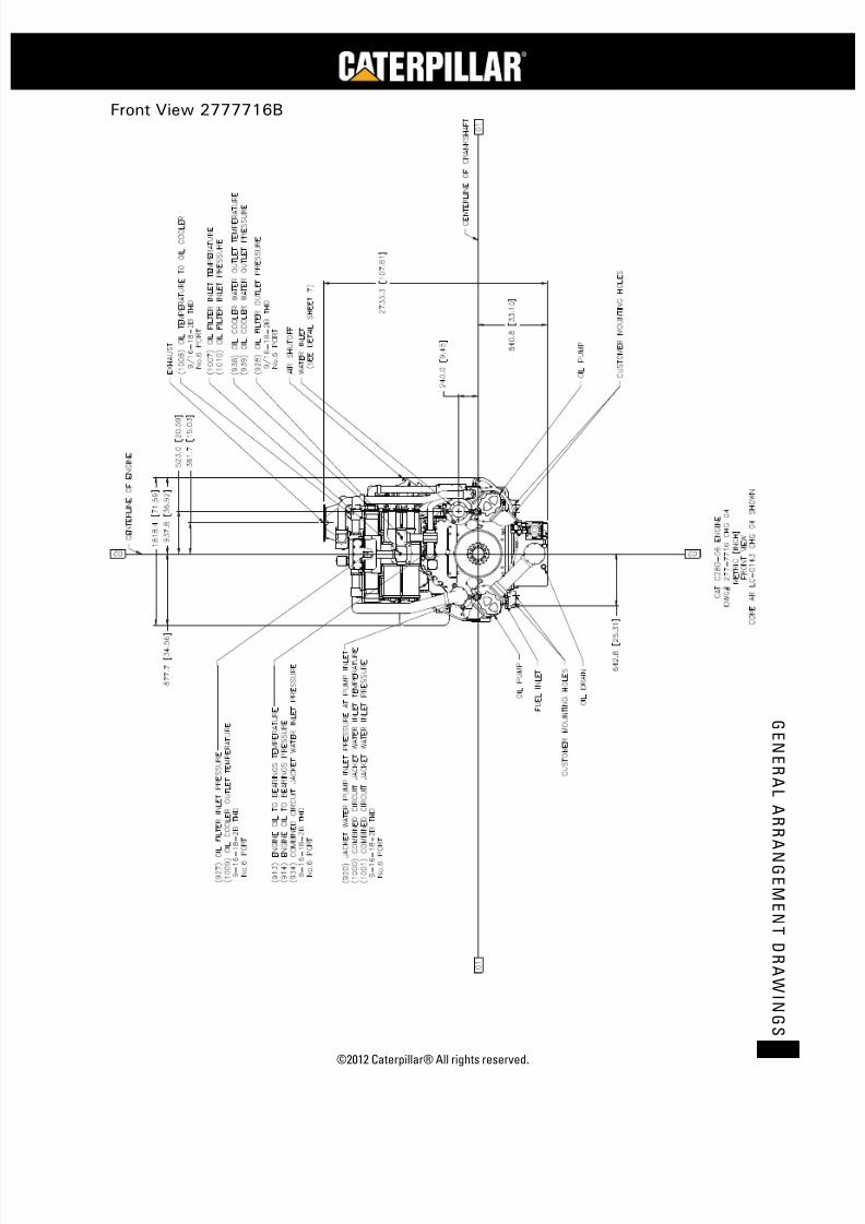
7/23/2019 1.- c280 Epa Tier 2 - Imo II Marine Project Guide
http://slidepdf.com/reader/full/1-c280-epa-tier-2-imo-ii-marine-project-guide 153/222
©2012 Caterpillar® All rights reserved. 145
G E N E R A L A R R A N G E ME N T D R A WI N G S
Front View 2777716B

7/23/2019 1.- c280 Epa Tier 2 - Imo II Marine Project Guide
http://slidepdf.com/reader/full/1-c280-epa-tier-2-imo-ii-marine-project-guide 154/222
C28
MARINE PROJECT GUIDE
©2012 Caterpillar® All rights reserved.146
G E N E R A L A R R A N G E M E N
T D R A W I N G S
Left Side View 2777716C

7/23/2019 1.- c280 Epa Tier 2 - Imo II Marine Project Guide
http://slidepdf.com/reader/full/1-c280-epa-tier-2-imo-ii-marine-project-guide 155/222
©2012 Caterpillar® All rights reserved. 147
G E N E R A L A R R A N G E ME N T D R A WI N G S
Rear View 2777716D
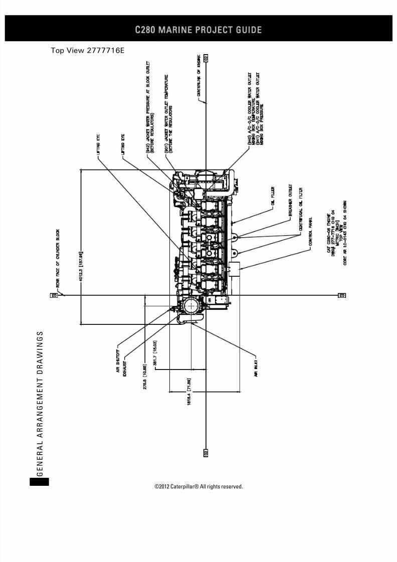
7/23/2019 1.- c280 Epa Tier 2 - Imo II Marine Project Guide
http://slidepdf.com/reader/full/1-c280-epa-tier-2-imo-ii-marine-project-guide 156/222
C28
MARINE PROJECT GUIDE
©2012 Caterpillar® All rights reserved.148
G E N E R A L A R R A N G E M E N
T D R A W I N G S
Top View 2777716E

7/23/2019 1.- c280 Epa Tier 2 - Imo II Marine Project Guide
http://slidepdf.com/reader/full/1-c280-epa-tier-2-imo-ii-marine-project-guide 157/222
©2012 Caterpillar® All rights reserved. 149
G E N E R A L A R R A N G E ME N T D R A WI N G S
ront and Left Side View 2777716F

7/23/2019 1.- c280 Epa Tier 2 - Imo II Marine Project Guide
http://slidepdf.com/reader/full/1-c280-epa-tier-2-imo-ii-marine-project-guide 158/222
C28
MARINE PROJECT GUIDE
©2012 Caterpillar® All rights reserved.150
G E N E R A L A R R A N G E M E N
T D R A W I N G S
Foot Print 2777716G

7/23/2019 1.- c280 Epa Tier 2 - Imo II Marine Project Guide
http://slidepdf.com/reader/full/1-c280-epa-tier-2-imo-ii-marine-project-guide 159/222
©2012 Caterpillar® All rights reserved. 151
G E N E R A L A R R A N G E ME N T D R A WI N G S
Connections Details 2777716H

7/23/2019 1.- c280 Epa Tier 2 - Imo II Marine Project Guide
http://slidepdf.com/reader/full/1-c280-epa-tier-2-imo-ii-marine-project-guide 160/222
C28
MARINE PROJECT GUIDE
©2012 Caterpillar® All rights reserved.152
G E N E R A L A R R A N G E M E N
T D R A W I N G S
Instrument Mounting 2777716I

7/23/2019 1.- c280 Epa Tier 2 - Imo II Marine Project Guide
http://slidepdf.com/reader/full/1-c280-epa-tier-2-imo-ii-marine-project-guide 161/222
©2012 Caterpillar® All rights reserved. 153
G E N E R A L A R R A N G E ME N T D R A WI N G S
C280-8 Engine Only
Right Side 2777717A
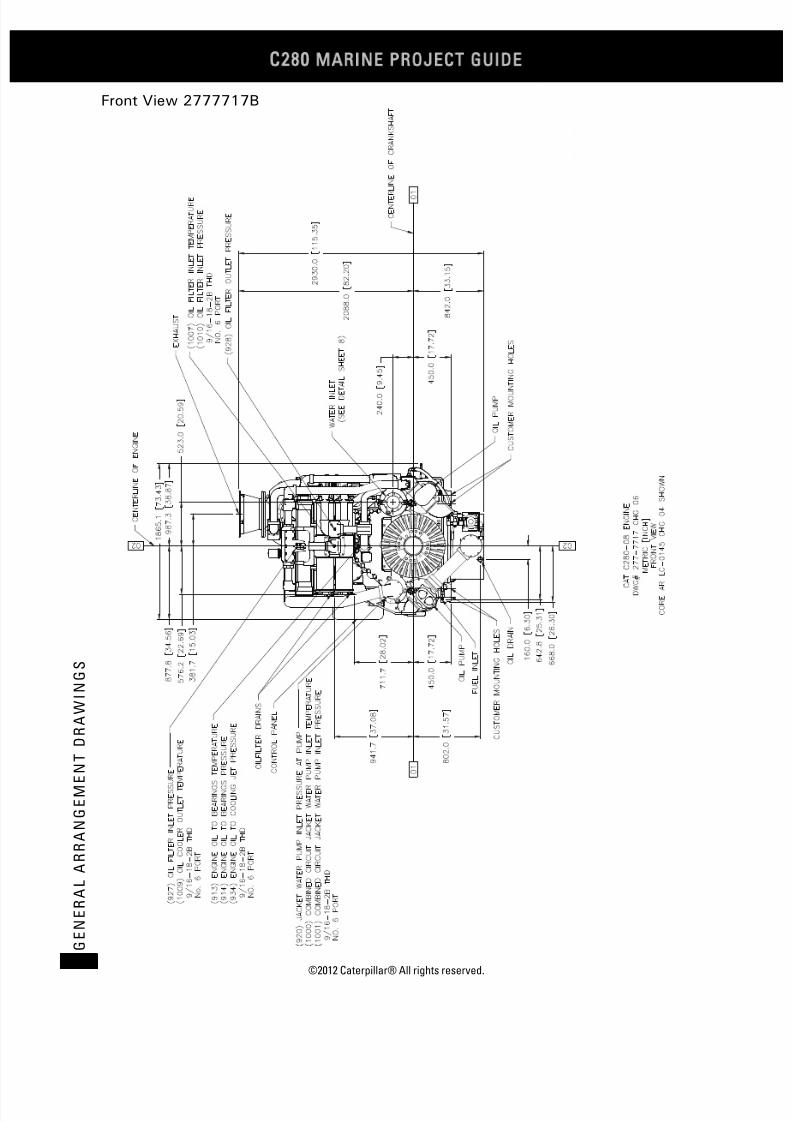
7/23/2019 1.- c280 Epa Tier 2 - Imo II Marine Project Guide
http://slidepdf.com/reader/full/1-c280-epa-tier-2-imo-ii-marine-project-guide 162/222
C28
MARINE PROJECT GUIDE
©2012 Caterpillar® All rights reserved.154
G E N E R A L A R R A N G E M E N
T D R A W I N G S
Front View 2777717B
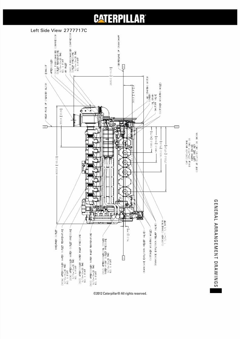
7/23/2019 1.- c280 Epa Tier 2 - Imo II Marine Project Guide
http://slidepdf.com/reader/full/1-c280-epa-tier-2-imo-ii-marine-project-guide 163/222
©2012 Caterpillar® All rights reserved. 155
G E N E R A L A R R A N G E ME N T D R A WI N G S
Left Side View 2777717C

7/23/2019 1.- c280 Epa Tier 2 - Imo II Marine Project Guide
http://slidepdf.com/reader/full/1-c280-epa-tier-2-imo-ii-marine-project-guide 164/222
C28
MARINE PROJECT GUIDE
©2012 Caterpillar® All rights reserved.156
G E N E R A L A R R A N G E M E N
T D R A W I N G S
Rear View 2777717D

7/23/2019 1.- c280 Epa Tier 2 - Imo II Marine Project Guide
http://slidepdf.com/reader/full/1-c280-epa-tier-2-imo-ii-marine-project-guide 165/222
©2012 Caterpillar® All rights reserved. 157
G E N E R A L A R R A N G E ME N T D R A WI N G S
Top View 2777717E

7/23/2019 1.- c280 Epa Tier 2 - Imo II Marine Project Guide
http://slidepdf.com/reader/full/1-c280-epa-tier-2-imo-ii-marine-project-guide 166/222
C28
MARINE PROJECT GUIDE
©2012 Caterpillar® All rights reserved.158
G E N E R A L A R R A N G E M E N
T D R A W I N G S
Foot Print 2777717F

7/23/2019 1.- c280 Epa Tier 2 - Imo II Marine Project Guide
http://slidepdf.com/reader/full/1-c280-epa-tier-2-imo-ii-marine-project-guide 167/222
©2012 Caterpillar® All rights reserved. 159
G E N E R A L A R R A N G E ME N T D R A WI N G S
Left Side and Front View 2777717G
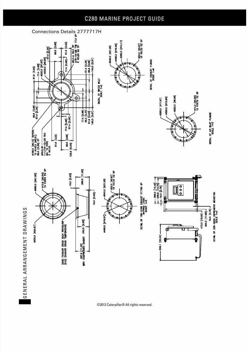
7/23/2019 1.- c280 Epa Tier 2 - Imo II Marine Project Guide
http://slidepdf.com/reader/full/1-c280-epa-tier-2-imo-ii-marine-project-guide 168/222
C28
MARINE PROJECT GUIDE
©2012 Caterpillar® All rights reserved.160
G E N E R A L A R R A N G E M E N
T D R A W I N G S
Connections Details 2777717H

7/23/2019 1.- c280 Epa Tier 2 - Imo II Marine Project Guide
http://slidepdf.com/reader/full/1-c280-epa-tier-2-imo-ii-marine-project-guide 169/222
©2012 Caterpillar® All rights reserved. 161
G E N E R A L A R R A N G E ME N T D R A WI N G S
C280-12 Engine Only
Right Side 2777718A

7/23/2019 1.- c280 Epa Tier 2 - Imo II Marine Project Guide
http://slidepdf.com/reader/full/1-c280-epa-tier-2-imo-ii-marine-project-guide 170/222
C28
MARINE PROJECT GUIDE
©2012 Caterpillar® All rights reserved.162
G E N E R A L A R R A N G E M E N
T D R A W I N G S
Front View 2777718B

7/23/2019 1.- c280 Epa Tier 2 - Imo II Marine Project Guide
http://slidepdf.com/reader/full/1-c280-epa-tier-2-imo-ii-marine-project-guide 171/222
©2012 Caterpillar® All rights reserved. 163
G E N E R A L A R R A N G E ME N T D R A WI N G S
Left Side View 2777718C
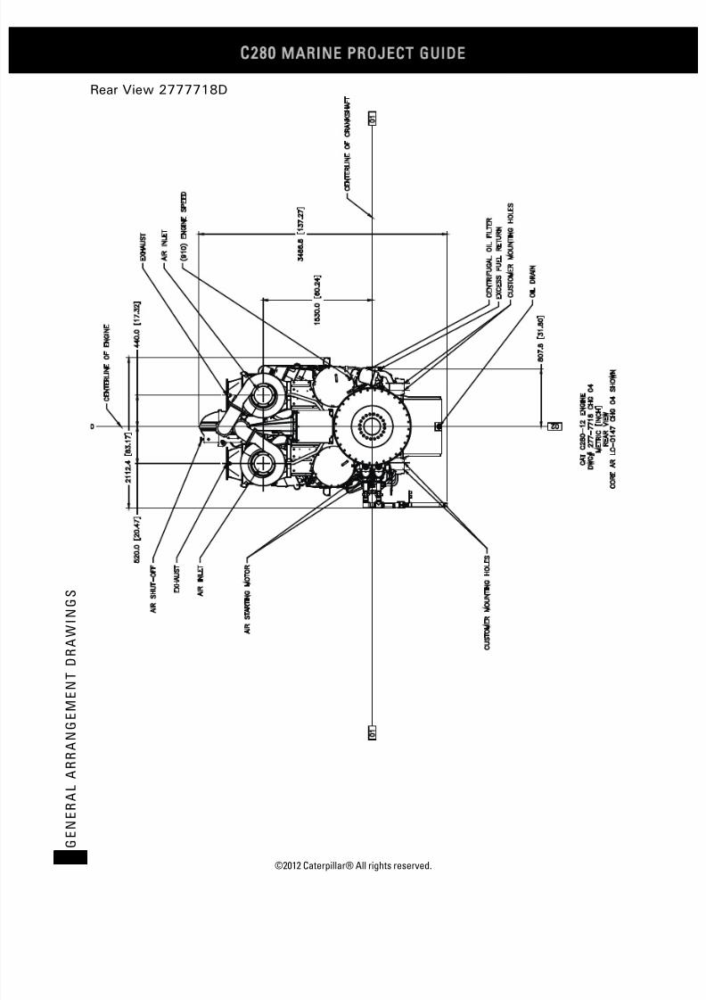
7/23/2019 1.- c280 Epa Tier 2 - Imo II Marine Project Guide
http://slidepdf.com/reader/full/1-c280-epa-tier-2-imo-ii-marine-project-guide 172/222
C28
MARINE PROJECT GUIDE
©2012 Caterpillar® All rights reserved.164
G E N E R A L A R R A N G E M E N
T D R A W I N G S
Rear View 2777718D

7/23/2019 1.- c280 Epa Tier 2 - Imo II Marine Project Guide
http://slidepdf.com/reader/full/1-c280-epa-tier-2-imo-ii-marine-project-guide 173/222
©2012 Caterpillar® All rights reserved. 165
G E N E R A L A R R A N G E ME N T D R A WI N G S
Top View 2777718E

7/23/2019 1.- c280 Epa Tier 2 - Imo II Marine Project Guide
http://slidepdf.com/reader/full/1-c280-epa-tier-2-imo-ii-marine-project-guide 174/222
C28
MARINE PROJECT GUIDE
©2012 Caterpillar® All rights reserved.166
G E N E R A L A R R A N G E M E N
T D R A W I N G S
Foot Print 2777718F
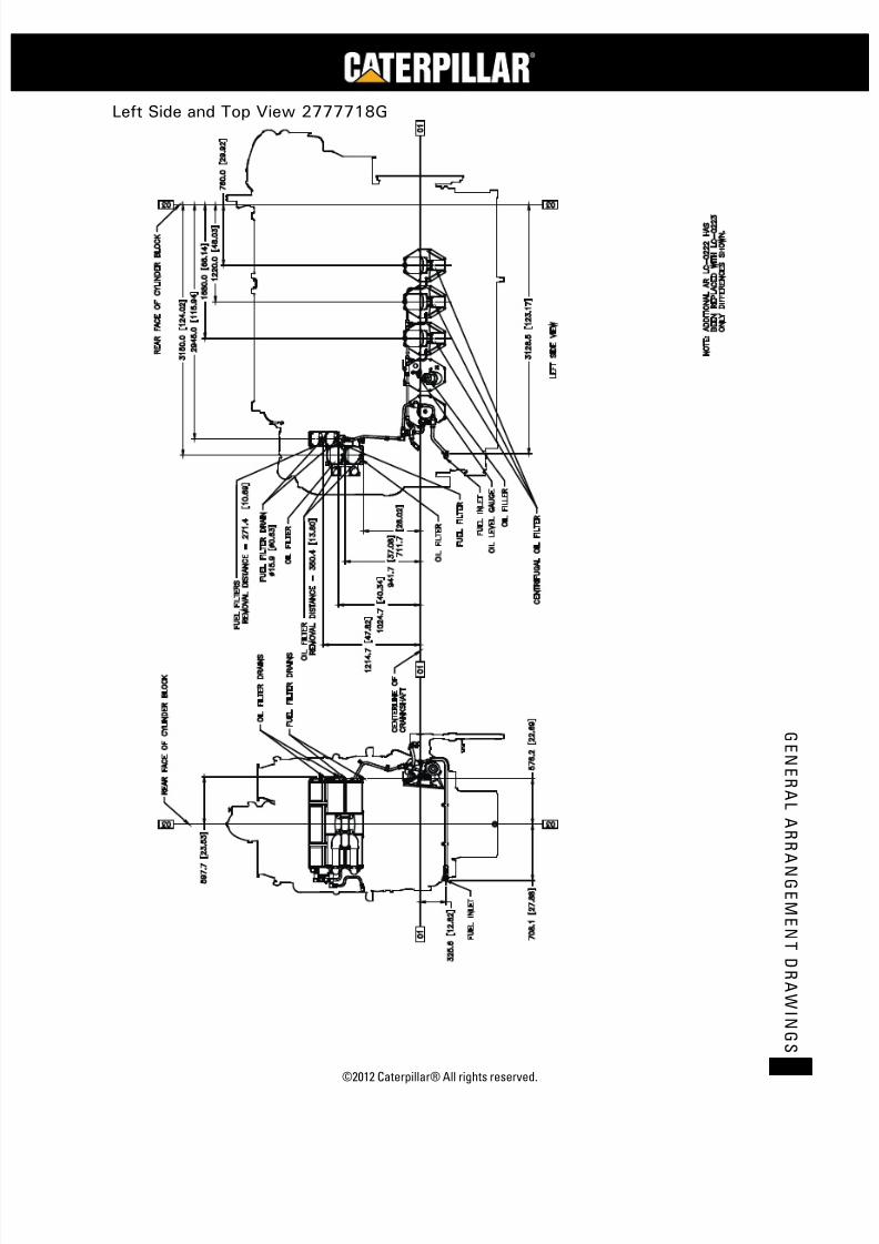
7/23/2019 1.- c280 Epa Tier 2 - Imo II Marine Project Guide
http://slidepdf.com/reader/full/1-c280-epa-tier-2-imo-ii-marine-project-guide 175/222
©2012 Caterpillar® All rights reserved. 167
G E N E R A L A R R A N G E ME N T D R A WI N G S
Left Side and Top View 2777718G

7/23/2019 1.- c280 Epa Tier 2 - Imo II Marine Project Guide
http://slidepdf.com/reader/full/1-c280-epa-tier-2-imo-ii-marine-project-guide 176/222
C28
MARINE PROJECT GUIDE
©2012 Caterpillar® All rights reserved.168
G E N E R A L A R R A N G E M E N
T D R A W I N G S
Connections Details 2777718H

7/23/2019 1.- c280 Epa Tier 2 - Imo II Marine Project Guide
http://slidepdf.com/reader/full/1-c280-epa-tier-2-imo-ii-marine-project-guide 177/222
©2012 Caterpillar® All rights reserved. 169
G E N E R A L A R R A N G E ME N T D R A WI N G S
C280-16 Engine Only
Right Side 2777719A

7/23/2019 1.- c280 Epa Tier 2 - Imo II Marine Project Guide
http://slidepdf.com/reader/full/1-c280-epa-tier-2-imo-ii-marine-project-guide 178/222
C28
MARINE PROJECT GUIDE
©2012 Caterpillar® All rights reserved.170
G E N E R A L A R R A N G E M E N
T D R A W I N G S
Front View 2777719B
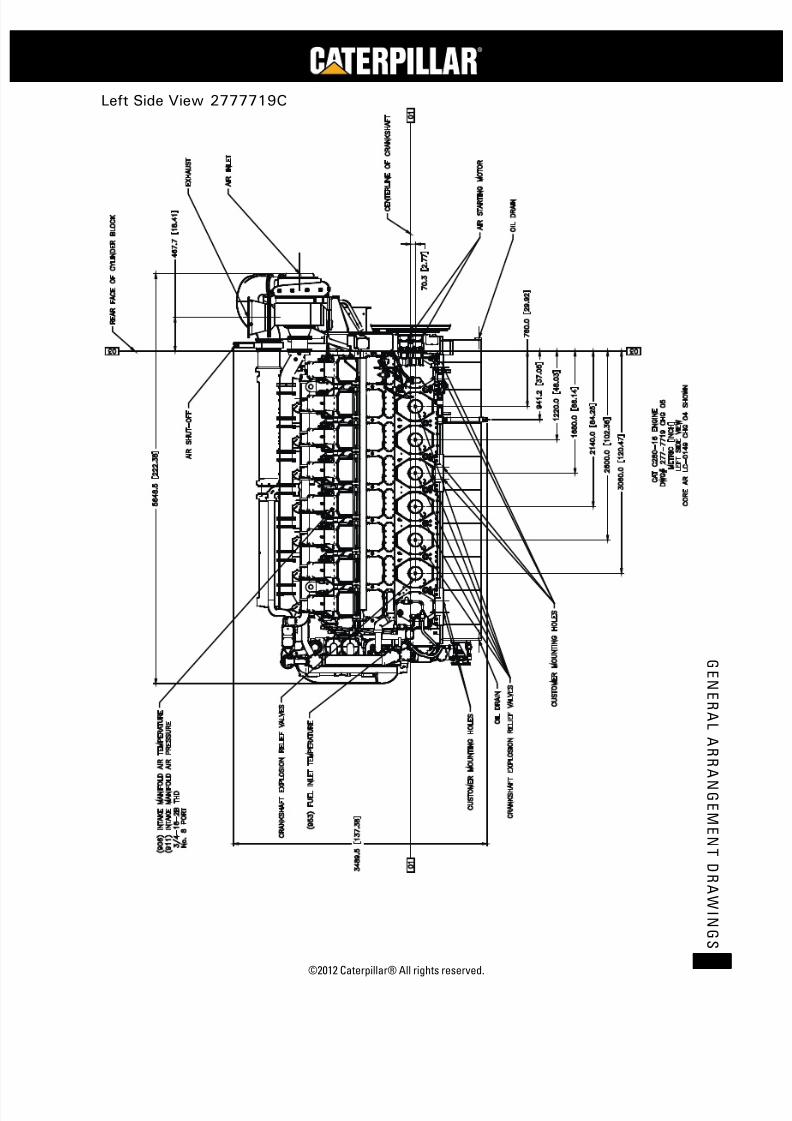
7/23/2019 1.- c280 Epa Tier 2 - Imo II Marine Project Guide
http://slidepdf.com/reader/full/1-c280-epa-tier-2-imo-ii-marine-project-guide 179/222
©2012 Caterpillar® All rights reserved. 171
G E N E R A L A R R A N G E ME N T D R A WI N G S
Left Side View 2777719C
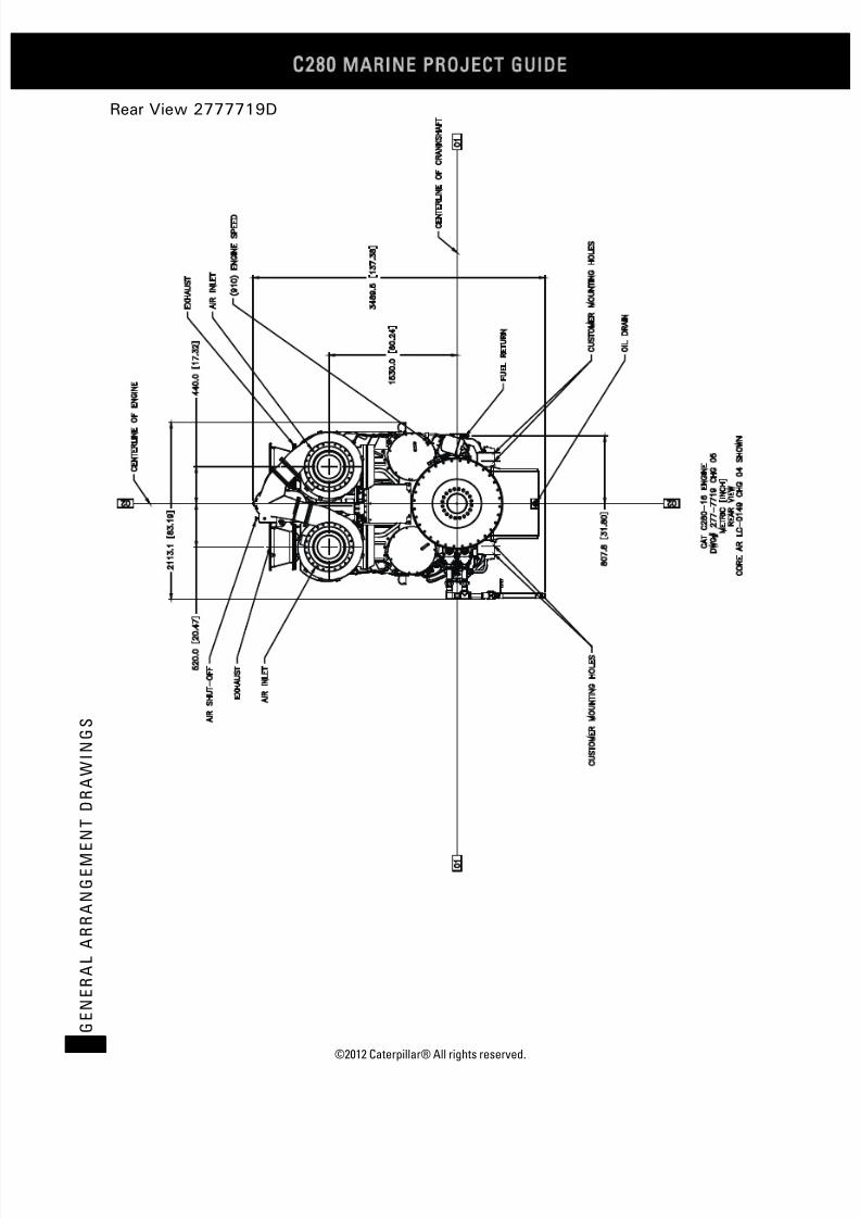
7/23/2019 1.- c280 Epa Tier 2 - Imo II Marine Project Guide
http://slidepdf.com/reader/full/1-c280-epa-tier-2-imo-ii-marine-project-guide 180/222
C28
MARINE PROJECT GUIDE
©2012 Caterpillar® All rights reserved.172
G E N E R A L A R R A N G E M E N
T D R A W I N G S
Rear View 2777719D

7/23/2019 1.- c280 Epa Tier 2 - Imo II Marine Project Guide
http://slidepdf.com/reader/full/1-c280-epa-tier-2-imo-ii-marine-project-guide 181/222
©2012 Caterpillar® All rights reserved. 173
G E N E R A L A R R A N G E ME N T D R A WI N G S
Top View 2777719E

7/23/2019 1.- c280 Epa Tier 2 - Imo II Marine Project Guide
http://slidepdf.com/reader/full/1-c280-epa-tier-2-imo-ii-marine-project-guide 182/222
C28
MARINE PROJECT GUIDE
©2012 Caterpillar® All rights reserved.174
G E N E R A L A R R A N G E M E N
T D R A W I N G S
Foot Print 2777719F

7/23/2019 1.- c280 Epa Tier 2 - Imo II Marine Project Guide
http://slidepdf.com/reader/full/1-c280-epa-tier-2-imo-ii-marine-project-guide 183/222
©2012 Caterpillar® All rights reserved. 175
G E N E R A L A R R A N G E ME N T D R A WI N G S
Left Side View 2777719G

7/23/2019 1.- c280 Epa Tier 2 - Imo II Marine Project Guide
http://slidepdf.com/reader/full/1-c280-epa-tier-2-imo-ii-marine-project-guide 184/222
C28
MARINE PROJECT GUIDE
©2012 Caterpillar® All rights reserved.176
G E N E R A L A R R A N G E M E N
T D R A W I N G S
Top View 2777719H

7/23/2019 1.- c280 Epa Tier 2 - Imo II Marine Project Guide
http://slidepdf.com/reader/full/1-c280-epa-tier-2-imo-ii-marine-project-guide 185/222
©2012 Caterpillar® All rights reserved. 177
G E N E R A L A R R A N G E ME N T D R A WI N G S
Connections Details 2777719I

7/23/2019 1.- c280 Epa Tier 2 - Imo II Marine Project Guide
http://slidepdf.com/reader/full/1-c280-epa-tier-2-imo-ii-marine-project-guide 186/222
C28
MARINE PROJECT GUIDE
©2012 Caterpillar® All rights reserved.178
G E N E R A L A R R A N G E M E N
T D R A W I N G S
C280-16 Front Mounted Turbocharger Engine
Right Side

7/23/2019 1.- c280 Epa Tier 2 - Imo II Marine Project Guide
http://slidepdf.com/reader/full/1-c280-epa-tier-2-imo-ii-marine-project-guide 187/222
©2012 Caterpillar® All rights reserved. 179
G E N E R A L A R R A N G E ME N T D R A WI N G S
Engine Front and Rear View
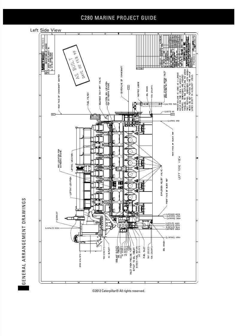
7/23/2019 1.- c280 Epa Tier 2 - Imo II Marine Project Guide
http://slidepdf.com/reader/full/1-c280-epa-tier-2-imo-ii-marine-project-guide 188/222
C28
MARINE PROJECT GUIDE
©2012 Caterpillar® All rights reserved.180
G E N E R A L A R R A N G E M E N
T D R A W I N G S
Left Side View

7/23/2019 1.- c280 Epa Tier 2 - Imo II Marine Project Guide
http://slidepdf.com/reader/full/1-c280-epa-tier-2-imo-ii-marine-project-guide 189/222
©2012 Caterpillar® All rights reserved. 181
G E N E R A L A R R A N G E ME N T D R A WI N G S
Top View
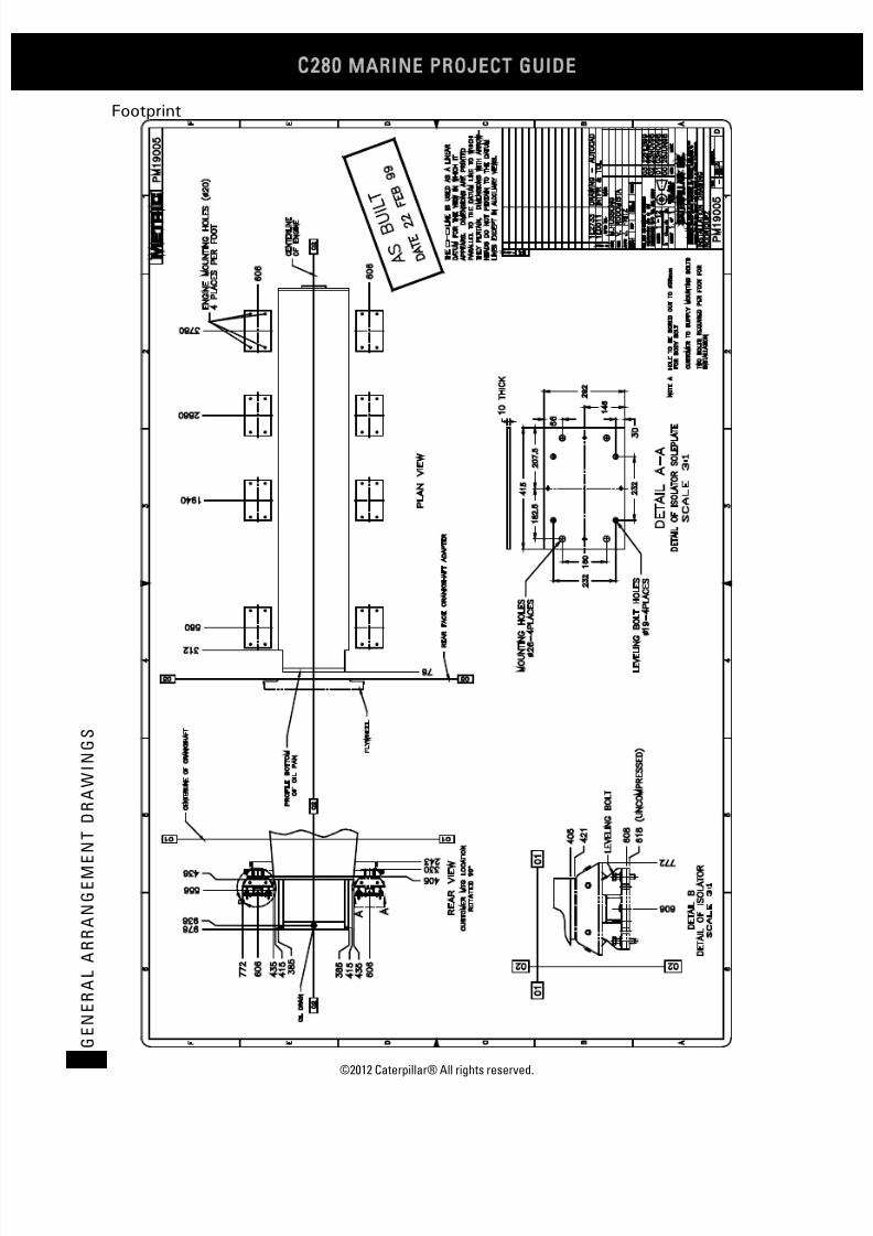
7/23/2019 1.- c280 Epa Tier 2 - Imo II Marine Project Guide
http://slidepdf.com/reader/full/1-c280-epa-tier-2-imo-ii-marine-project-guide 190/222
C28
MARINE PROJECT GUIDE
©2012 Caterpillar® All rights reserved.182
G E N E R A L A R R A N G E M E N
T D R A W I N G S
Footprint
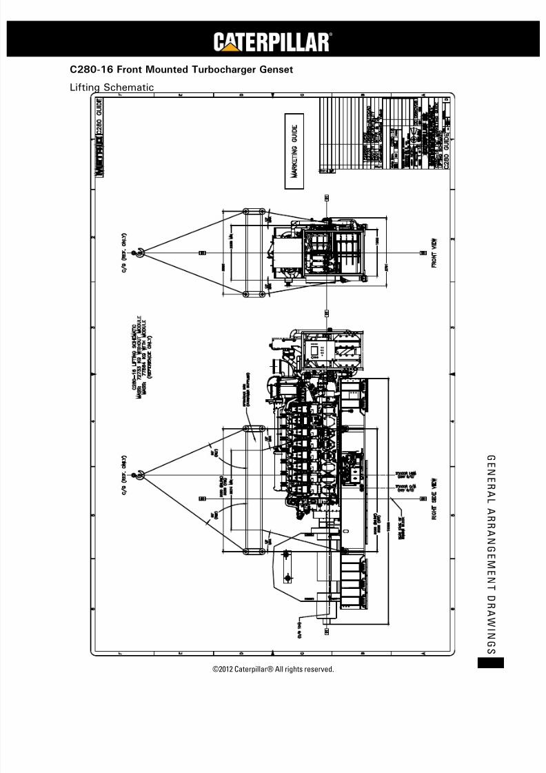
7/23/2019 1.- c280 Epa Tier 2 - Imo II Marine Project Guide
http://slidepdf.com/reader/full/1-c280-epa-tier-2-imo-ii-marine-project-guide 191/222
©2012 Caterpillar® All rights reserved. 183
G E N E R A L A R R A N G E ME N T D R A WI N G S
C280-16 Front Mounted Turbocharger Genset
Lifting Schematic

7/23/2019 1.- c280 Epa Tier 2 - Imo II Marine Project Guide
http://slidepdf.com/reader/full/1-c280-epa-tier-2-imo-ii-marine-project-guide 192/222
C28
MARINE PROJECT GUIDE
©2012 Caterpillar® All rights reserved.184
G E N E R A L A R R A N G E M E N
T D R A W I N G S
Right Side View
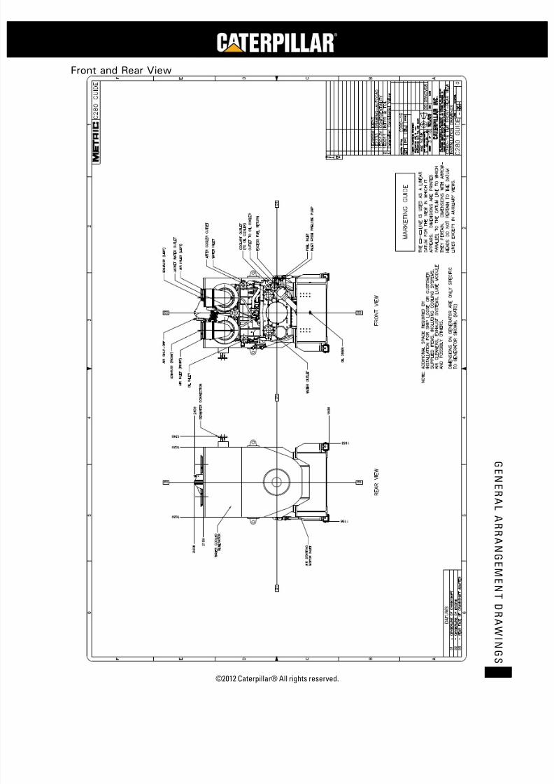
7/23/2019 1.- c280 Epa Tier 2 - Imo II Marine Project Guide
http://slidepdf.com/reader/full/1-c280-epa-tier-2-imo-ii-marine-project-guide 193/222
©2012 Caterpillar® All rights reserved. 185
G E N E R A L A R R A N G E ME N T D R A WI N G S
Front and Rear View
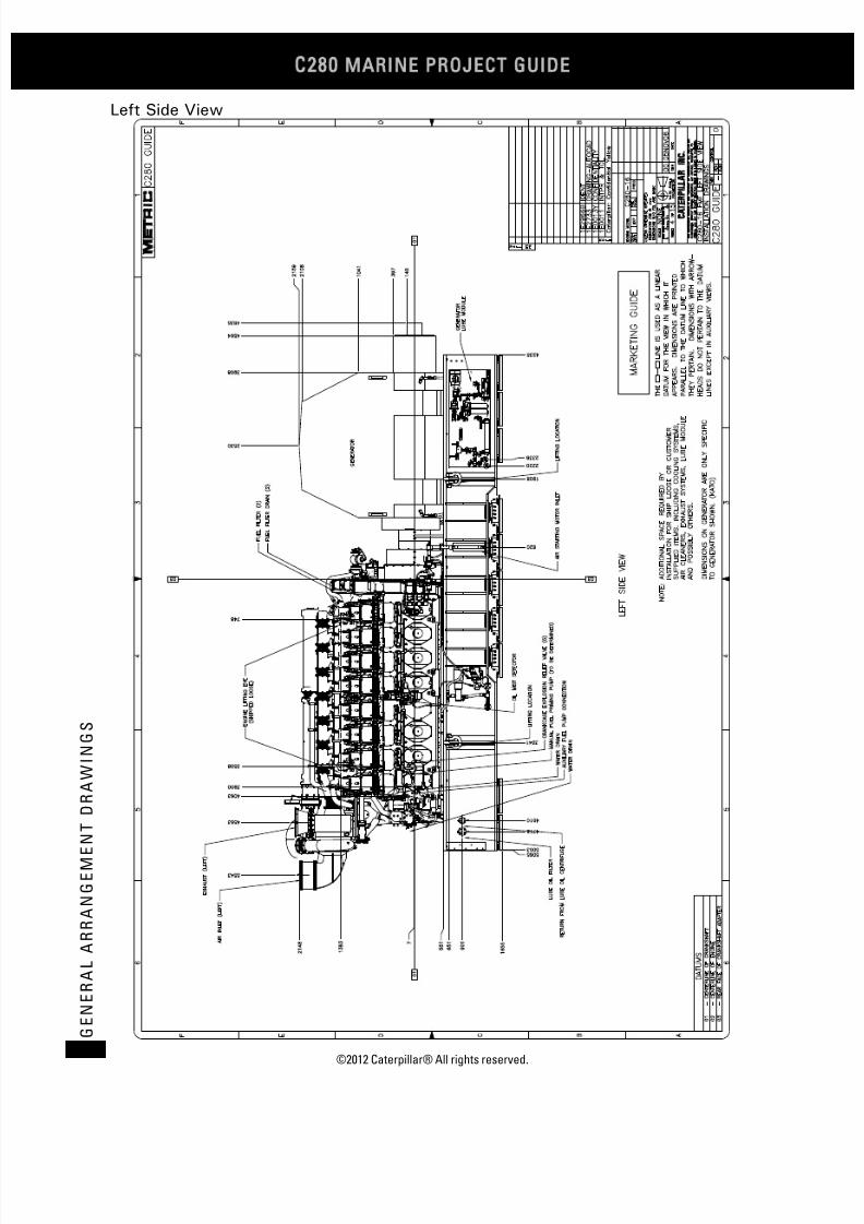
7/23/2019 1.- c280 Epa Tier 2 - Imo II Marine Project Guide
http://slidepdf.com/reader/full/1-c280-epa-tier-2-imo-ii-marine-project-guide 194/222
C28
MARINE PROJECT GUIDE
©2012 Caterpillar® All rights reserved.186
G E N E R A L A R R A N G E M E N
T D R A W I N G S
Left Side View
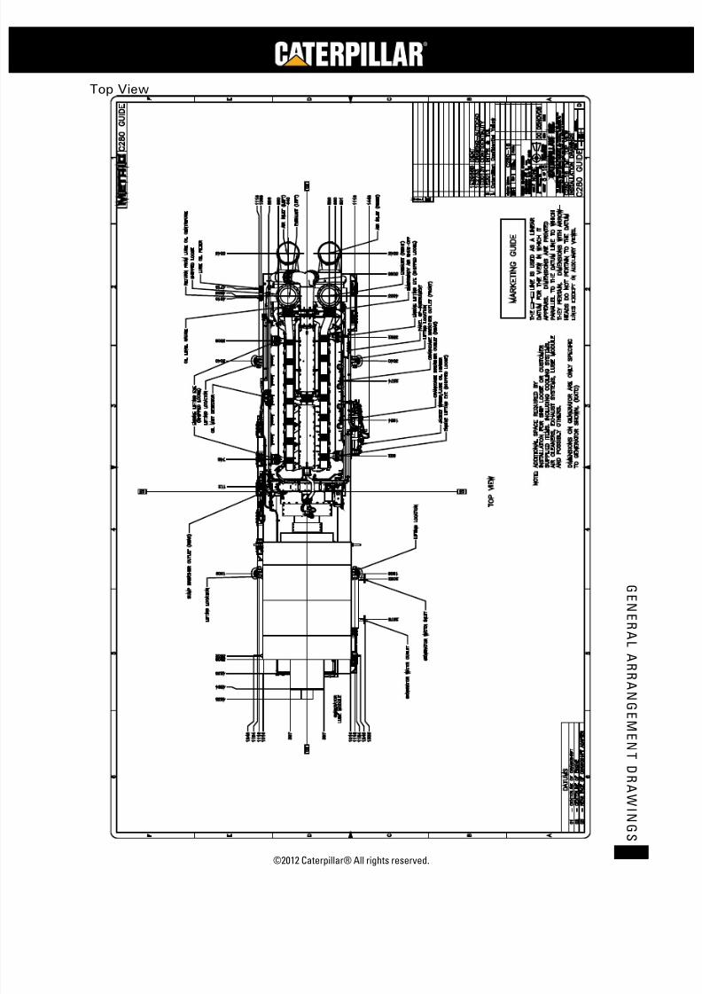
7/23/2019 1.- c280 Epa Tier 2 - Imo II Marine Project Guide
http://slidepdf.com/reader/full/1-c280-epa-tier-2-imo-ii-marine-project-guide 195/222
©2012 Caterpillar® All rights reserved. 187
G E N E R A L A R R A N G E ME N T D R A WI N G S
Top View

7/23/2019 1.- c280 Epa Tier 2 - Imo II Marine Project Guide
http://slidepdf.com/reader/full/1-c280-epa-tier-2-imo-ii-marine-project-guide 196/222
C28
MARINE PROJECT GUIDE
©2012 Caterpillar® All rights reserved.188
G E N E R A L A R R A N G E M E N
T D R A W I N G S
Footprint
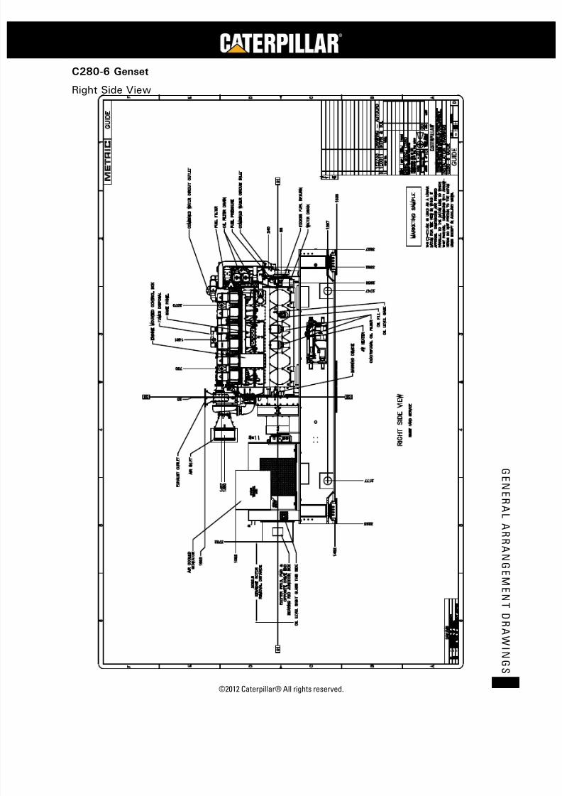
7/23/2019 1.- c280 Epa Tier 2 - Imo II Marine Project Guide
http://slidepdf.com/reader/full/1-c280-epa-tier-2-imo-ii-marine-project-guide 197/222
©2012 Caterpillar® All rights reserved. 189
G E N E R A L A R R A N G E ME N T D R A WI N G S
C280-6 Genset
Right Side View

7/23/2019 1.- c280 Epa Tier 2 - Imo II Marine Project Guide
http://slidepdf.com/reader/full/1-c280-epa-tier-2-imo-ii-marine-project-guide 198/222
C28
MARINE PROJECT GUIDE
©2012 Caterpillar® All rights reserved.190
G E N E R A L A R R A N G E M E N
T D R A W I N G S
Top View

7/23/2019 1.- c280 Epa Tier 2 - Imo II Marine Project Guide
http://slidepdf.com/reader/full/1-c280-epa-tier-2-imo-ii-marine-project-guide 199/222
©2012 Caterpillar® All rights reserved. 191
G E N E R A L A R R A N G E ME N T D R A WI N G S
Right Side View
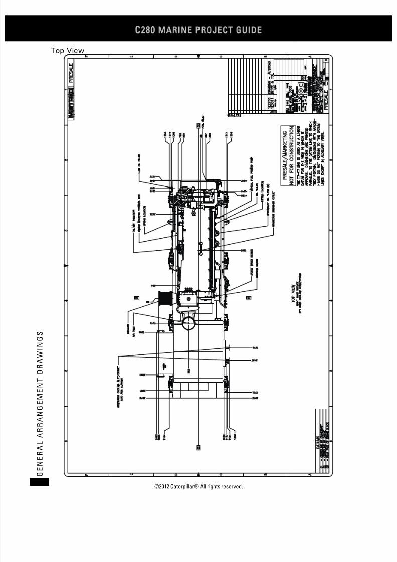
7/23/2019 1.- c280 Epa Tier 2 - Imo II Marine Project Guide
http://slidepdf.com/reader/full/1-c280-epa-tier-2-imo-ii-marine-project-guide 200/222
C28
MARINE PROJECT GUIDE
©2012 Caterpillar® All rights reserved.192
G E N E R A L A R R A N G E M E N
T D R A W I N G S
Top View
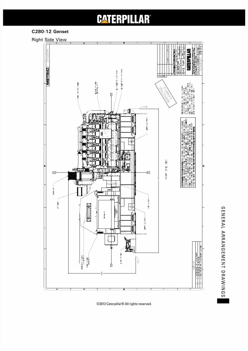
7/23/2019 1.- c280 Epa Tier 2 - Imo II Marine Project Guide
http://slidepdf.com/reader/full/1-c280-epa-tier-2-imo-ii-marine-project-guide 201/222
©2012 Caterpillar® All rights reserved. 193
G E N E R A L A R R A N G E ME N T D R A WI N G S
C280-12 Genset
Right Side View

7/23/2019 1.- c280 Epa Tier 2 - Imo II Marine Project Guide
http://slidepdf.com/reader/full/1-c280-epa-tier-2-imo-ii-marine-project-guide 202/222
C28
MARINE PROJECT GUIDE
©2012 Caterpillar® All rights reserved.194
G E N E R A L A R R A N G E M E N
T D R A W I N G S
Top View

7/23/2019 1.- c280 Epa Tier 2 - Imo II Marine Project Guide
http://slidepdf.com/reader/full/1-c280-epa-tier-2-imo-ii-marine-project-guide 203/222
©2012 Caterpillar® All rights reserved. 195
G E N E R A L A R R A N G E ME N T D R A WI N G S
C280-16 Genset
Right Side View
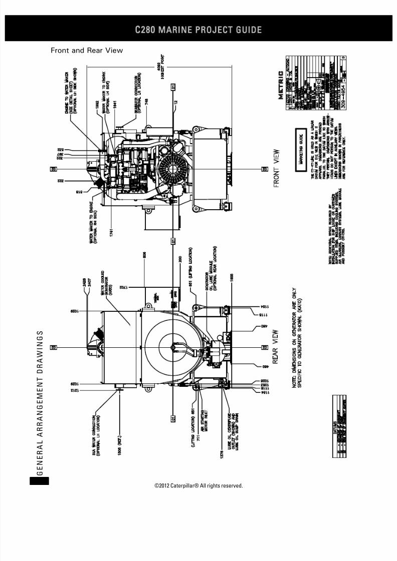
7/23/2019 1.- c280 Epa Tier 2 - Imo II Marine Project Guide
http://slidepdf.com/reader/full/1-c280-epa-tier-2-imo-ii-marine-project-guide 204/222
C28
MARINE PROJECT GUIDE
©2012 Caterpillar® All rights reserved.196
G E N E R A L A R R A N G E M E N
T D R A W I N G S
Front and Rear View

7/23/2019 1.- c280 Epa Tier 2 - Imo II Marine Project Guide
http://slidepdf.com/reader/full/1-c280-epa-tier-2-imo-ii-marine-project-guide 205/222
©2012 Caterpillar® All rights reserved. 197
G E N E R A L A R R A N G E ME N T D R A WI N G S
Left Side View
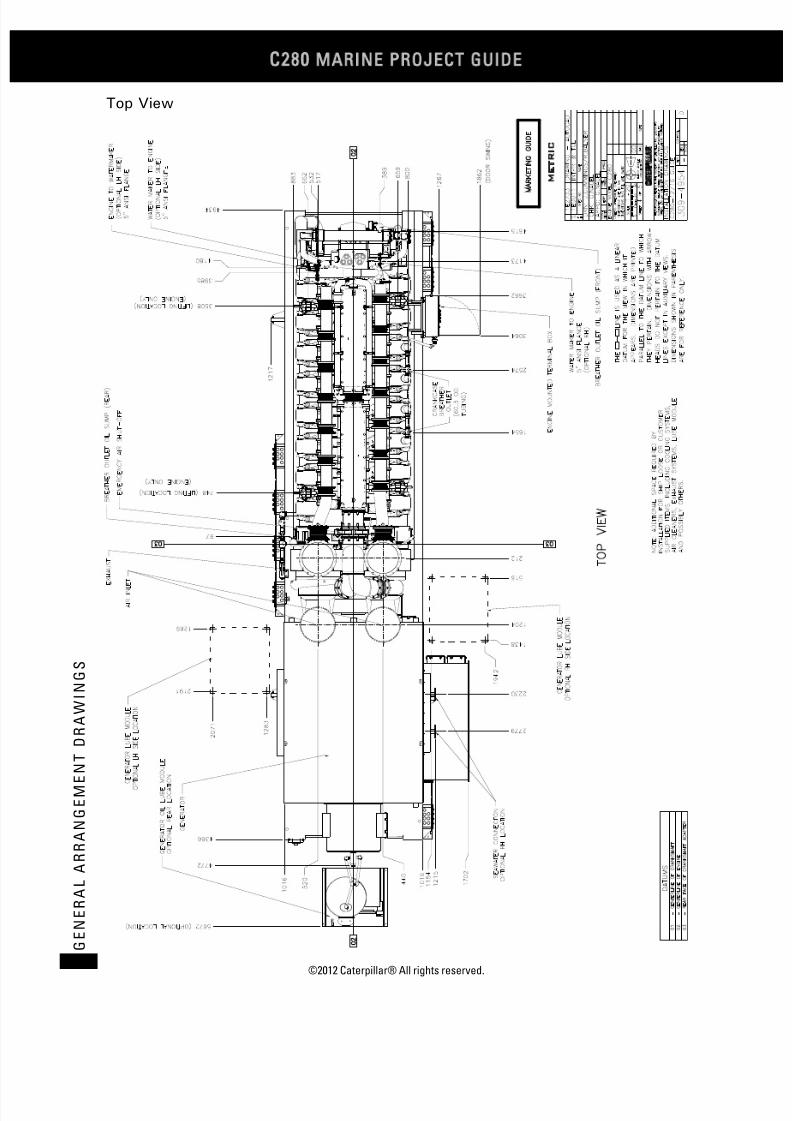
7/23/2019 1.- c280 Epa Tier 2 - Imo II Marine Project Guide
http://slidepdf.com/reader/full/1-c280-epa-tier-2-imo-ii-marine-project-guide 206/222
C28
MARINE PROJECT GUIDE
©2012 Caterpillar® All rights reserved.198
G E N E R A L A R R A N G E M E N
T D R A W I N G S
Top View

7/23/2019 1.- c280 Epa Tier 2 - Imo II Marine Project Guide
http://slidepdf.com/reader/full/1-c280-epa-tier-2-imo-ii-marine-project-guide 207/222
©2012 Caterpillar® All rights reserved. 199
G E N E R A L A R R A N G E ME N T D R A WI N G S
Plan View

7/23/2019 1.- c280 Epa Tier 2 - Imo II Marine Project Guide
http://slidepdf.com/reader/full/1-c280-epa-tier-2-imo-ii-marine-project-guide 208/222
C28
MARINE PROJECT GUIDE
©2012 Caterpillar® All rights reserved.200
G E N E R A L A R R A N G E M E N
T D R A W I N G S
Connection Data Sheet

7/23/2019 1.- c280 Epa Tier 2 - Imo II Marine Project Guide
http://slidepdf.com/reader/full/1-c280-epa-tier-2-imo-ii-marine-project-guide 209/222
©2012 Caterpillar® All rights reserved. 201
G E N E R A L A R R A N G E ME N T D R A WI N G S
Shipped Loose Items
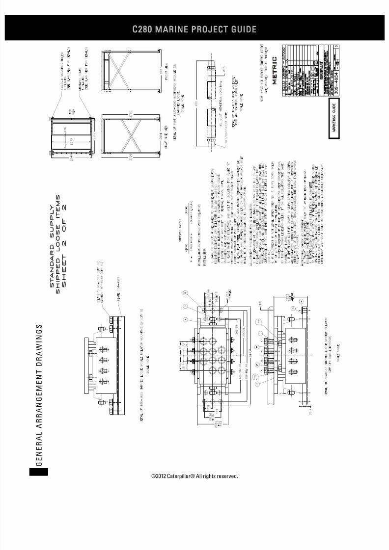
7/23/2019 1.- c280 Epa Tier 2 - Imo II Marine Project Guide
http://slidepdf.com/reader/full/1-c280-epa-tier-2-imo-ii-marine-project-guide 210/222
C28
MARINE PROJECT GUIDE
©2012 Caterpillar® All rights reserved.202
G E N E R A L A R R A N G E M E N
T D R A W I N G S

7/23/2019 1.- c280 Epa Tier 2 - Imo II Marine Project Guide
http://slidepdf.com/reader/full/1-c280-epa-tier-2-imo-ii-marine-project-guide 211/222
©2012 Caterpillar® All rights reserved. 203
G E N E R A L A R R A N G E ME N T D R A WI N G S
Optional Items
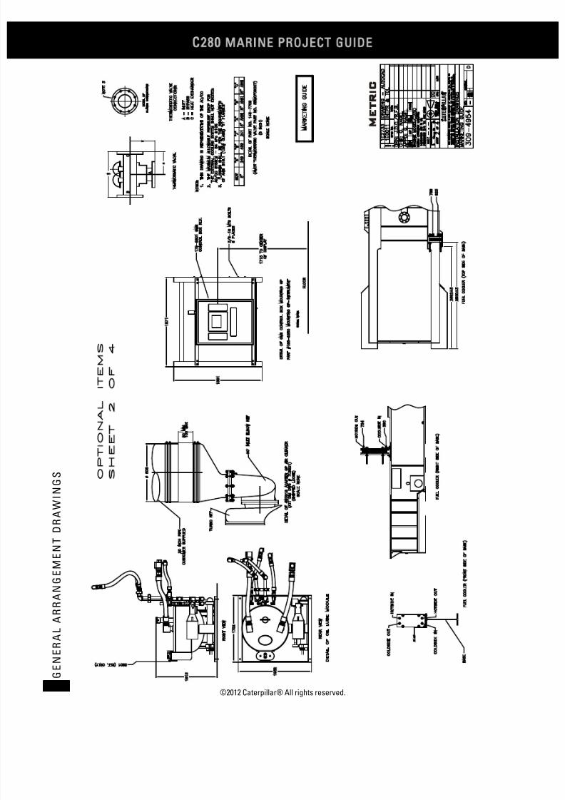
7/23/2019 1.- c280 Epa Tier 2 - Imo II Marine Project Guide
http://slidepdf.com/reader/full/1-c280-epa-tier-2-imo-ii-marine-project-guide 212/222
C28
MARINE PROJECT GUIDE
©2012 Caterpillar® All rights reserved.204
G E N E R A L A R R A N G E M E N
T D R A W I N G S
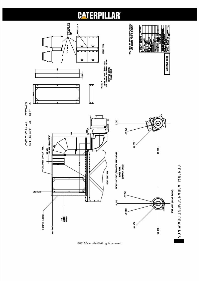
7/23/2019 1.- c280 Epa Tier 2 - Imo II Marine Project Guide
http://slidepdf.com/reader/full/1-c280-epa-tier-2-imo-ii-marine-project-guide 213/222
©2012 Caterpillar® All rights reserved. 205
G E N E R A L A R R A N G E ME N T D R A WI N G S

7/23/2019 1.- c280 Epa Tier 2 - Imo II Marine Project Guide
http://slidepdf.com/reader/full/1-c280-epa-tier-2-imo-ii-marine-project-guide 214/222
C28
MARINE PROJECT GUIDE
©2012 Caterpillar® All rights reserved.206
G E N E R A L A R R A N G E M E N
T D R A W I N G S

7/23/2019 1.- c280 Epa Tier 2 - Imo II Marine Project Guide
http://slidepdf.com/reader/full/1-c280-epa-tier-2-imo-ii-marine-project-guide 215/222
©2012 Caterpillar® All rights reserved. 207
G E N E R A L A R R A N G E ME N T D R A WI N G S
Lifting Schematic

7/23/2019 1.- c280 Epa Tier 2 - Imo II Marine Project Guide
http://slidepdf.com/reader/full/1-c280-epa-tier-2-imo-ii-marine-project-guide 216/222
C28
MARINE PROJECT GUIDE
©2012 Caterpillar® All rights reserved.208
G E N E R A L A R R A N G E M E N
T D R A W I N G S
Inline Engines Removal Distances
\
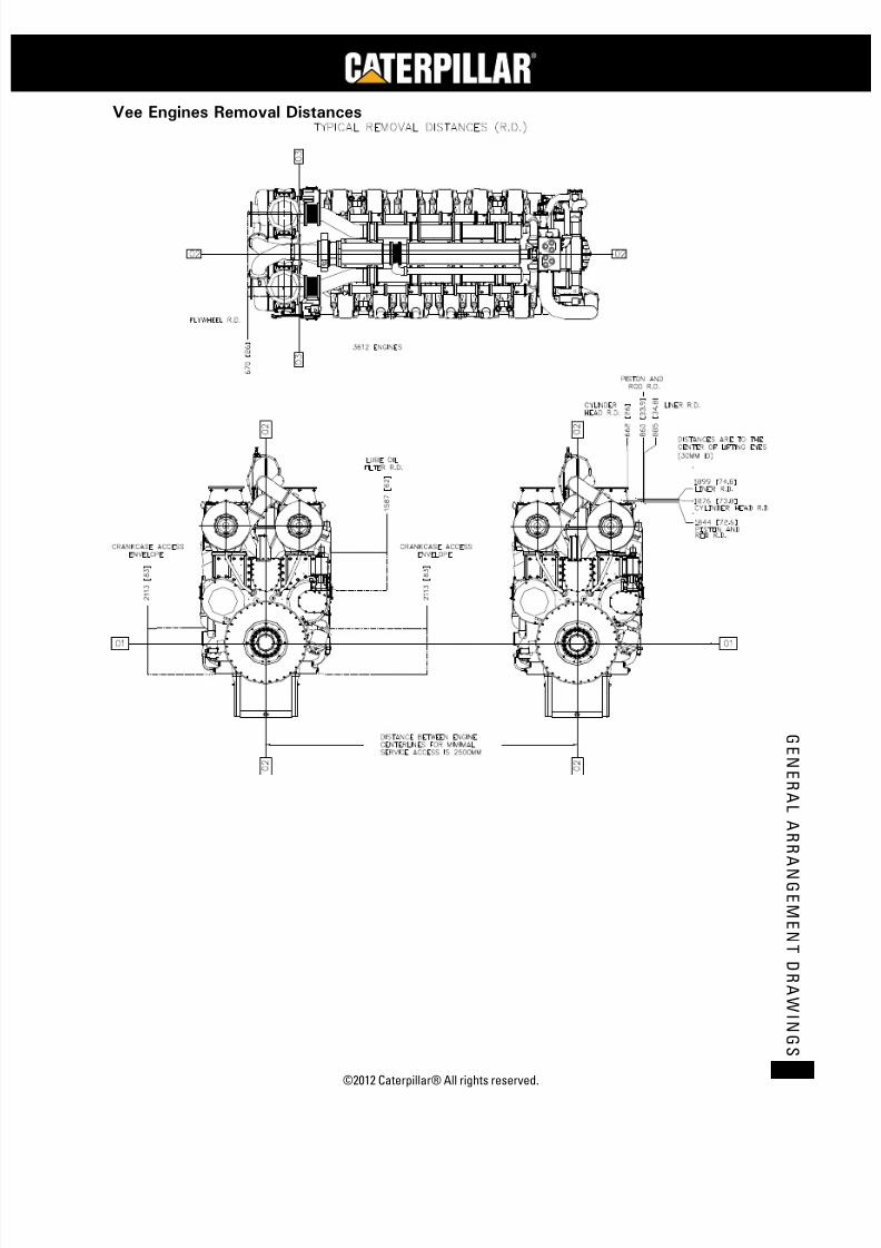
7/23/2019 1.- c280 Epa Tier 2 - Imo II Marine Project Guide
http://slidepdf.com/reader/full/1-c280-epa-tier-2-imo-ii-marine-project-guide 217/222
©2012 Caterpillar® All rights reserved. 209
G E N E R A L A R R A N G E ME N T D R A WI N G S
Vee Engines Removal Distances

7/23/2019 1.- c280 Epa Tier 2 - Imo II Marine Project Guide
http://slidepdf.com/reader/full/1-c280-epa-tier-2-imo-ii-marine-project-guide 218/222
C28
MARINE PROJECT GUIDE
©2012 Caterpillar® All rights reserved.210
G E N E R A L A R R A N G E M E N
T D R A W I N G S

7/23/2019 1.- c280 Epa Tier 2 - Imo II Marine Project Guide
http://slidepdf.com/reader/full/1-c280-epa-tier-2-imo-ii-marine-project-guide 219/222
©2012 Caterpillar® All rights reserved. 211
G E N E R A L A R R A N G E ME N T D R A WI N G S
Typical Supplied Auxiliary Equipment
AC/OC Thermostatic Valve
JW Thermostatic Valve
Lube Oil Thermostatic Valve

7/23/2019 1.- c280 Epa Tier 2 - Imo II Marine Project Guide
http://slidepdf.com/reader/full/1-c280-epa-tier-2-imo-ii-marine-project-guide 220/222
C28
MARINE PROJECT GUIDE
©2012 Caterpillar® All rights reserved.212
G E N E R A L A R R A N G E M E N
T D R A W I N G S
Jacket Water/Lube Oil Combination Heater
Prelubrication Pump
Fuel Pre Filter

7/23/2019 1.- c280 Epa Tier 2 - Imo II Marine Project Guide
http://slidepdf.com/reader/full/1-c280-epa-tier-2-imo-ii-marine-project-guide 221/222
©2012 Caterpillar® All rights reserved. 213
G E N E R A L A R R A N G E ME N T D R A WI N G S
Reference Material
The following information is provided as additional reference to subjectsdiscussed in this guide.
LEBM0600
3606 and 3608 Marine Project Guide
LEBM0465 3612 and 3616 Marine Project Guide
LEBW0006 C280 3600 Petroleum Offshore Project Guide
LEBW4985 C280 Commissioning Guide
SENR3593 Systems Operation, Testing and Adjusting (3612 and 3616 Engines)
SEBU6965 Operation and Maintenance Manual (3600 Distillate Fuel Engines)
SEBU7003 3600 Series and C280 Series Diesel Engine Fluids Recommendations
1E2566L Processing – Engine Preservation
7/23/2019 1.- c280 Epa Tier 2 - Imo II Marine Project Guide
http://slidepdf.com/reader/full/1-c280-epa-tier-2-imo-ii-marine-project-guide 222/222