1 business development (service). select location for reflector installation with clear view of...
TRANSCRIPT
1
Business Development (Service)


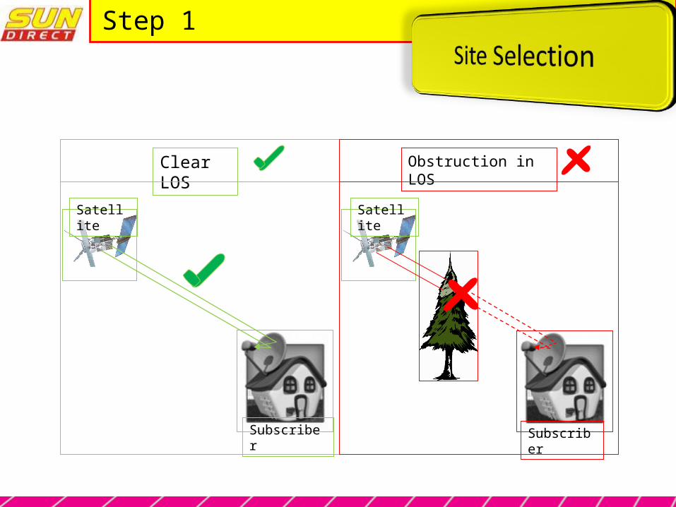
Select location for Reflector Installation with clear view of Satellite (Line Of Sight)
There should not be any partial / future obstruction in LOS like- Tree branches, Sheds,
Growing Tree, Under Construction Building etc.
Step 1
Satellite
Subscriber
Obstruction in LOS
Satellite
Subscriber
Clear LOS
Step 1

Pre-cautions
Reflector Installation Location : -
Should be minimum 5 Meters away from Bare Electrical Lines ( Overhead / Side )
Should be easily accessible for Maintenance / Service
Should not be accessible by Children / Pet Animals
Should be such that Rain / Water Drainage from Roof never hit the Reflector
Should not be in the Passage
Should not be in Damp Area
Always Prefer wall Mount option for Reflector Assembly
Never Install Reflector Assembly on Water Tank or wall of the Water Tank
Step 1
Step 1
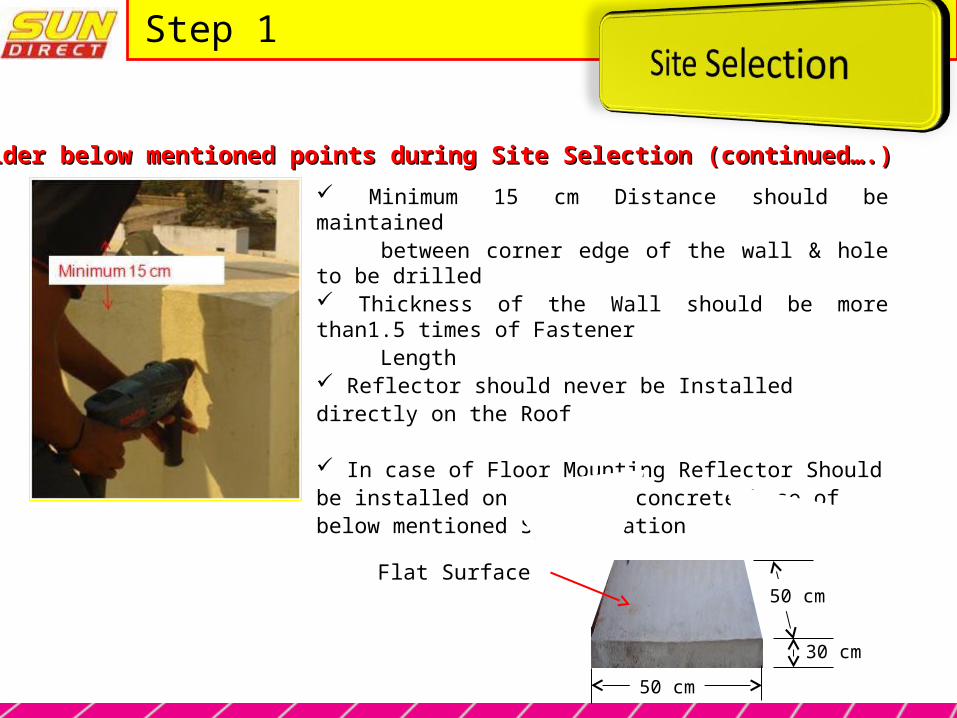
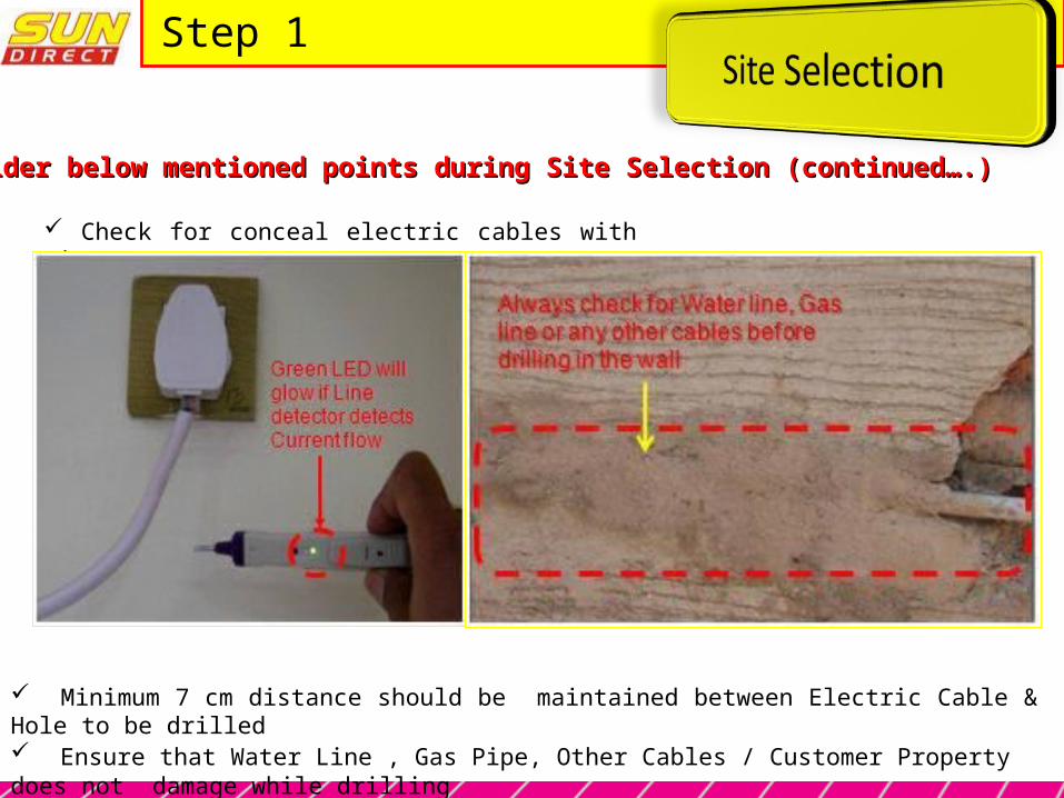
Also Consider below mentioned points during Site Selection (continued….) Also Consider below mentioned points during Site Selection (continued….)
Minimum 15 cm Distance should be maintained between corner edge of the wall & hole to be drilled Thickness of the Wall should be more than1.5 times of Fastener Length Reflector should never be Installed directly on the Roof
In case of Floor Mounting Reflector Should be installed on the Flat concrete base of below mentioned Specification
50 cm
50 cm
30 cm
Flat Surface
Also Consider below mentioned points during Site Selection (continued….) Also Consider below mentioned points during Site Selection (continued….)
Step 1
Check for conceal electric cables with Line Detector
Minimum 7 cm distance should be maintained between Electric Cable & Hole to be drilled Ensure that Water Line , Gas Pipe, Other Cables / Customer Property does not damage while drilling
Step 1
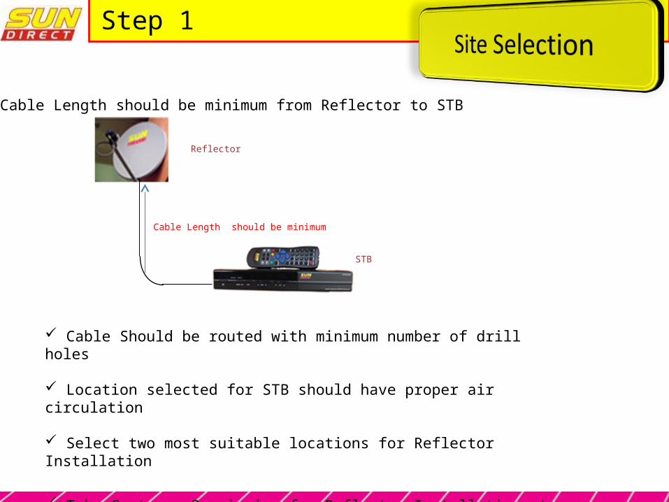
Cable Length should be minimum from Reflector to STB
Cable Should be routed with minimum number of drill holes
Location selected for STB should have proper air circulation
Select two most suitable locations for Reflector Installation
Take Customer Permission for Reflector Installation at best suitable location
Cable Length should be minimum
Reflector
STB
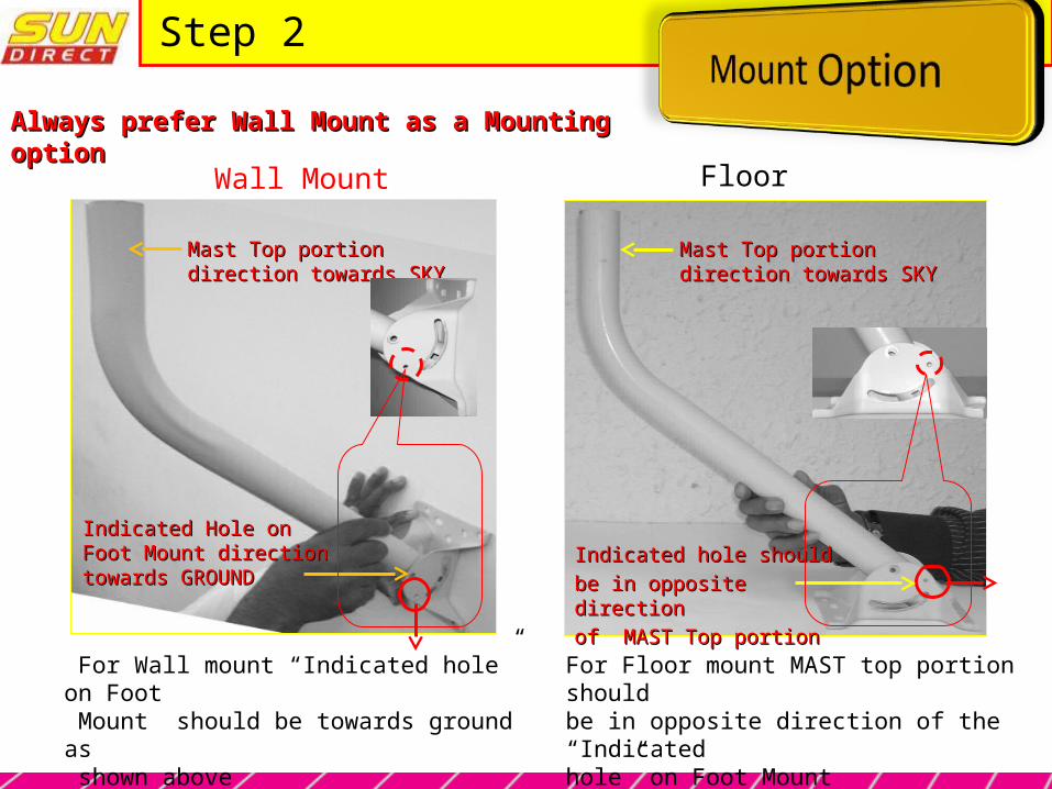
Always prefer Wall Mount as a Mounting Always prefer Wall Mount as a Mounting optionoption
For Wall mount “Indicated hole” on Foot Mount should be towards ground as shown above
For Floor mount MAST top portion should be in opposite direction of the “Indicated hole” on Foot Mount
Wall Mount
Mast Top portion direction Mast Top portion direction towards SKYtowards SKY
Indicated Hole on Foot Indicated Hole on Foot Mount direction towards Mount direction towards GROUNDGROUND
Floor Mount
Indicated hole should Indicated hole should be in opposite directionbe in opposite directionof MAST Top portionof MAST Top portion
Mast Top portion direction Mast Top portion direction towards SKYtowards SKY
Step 2
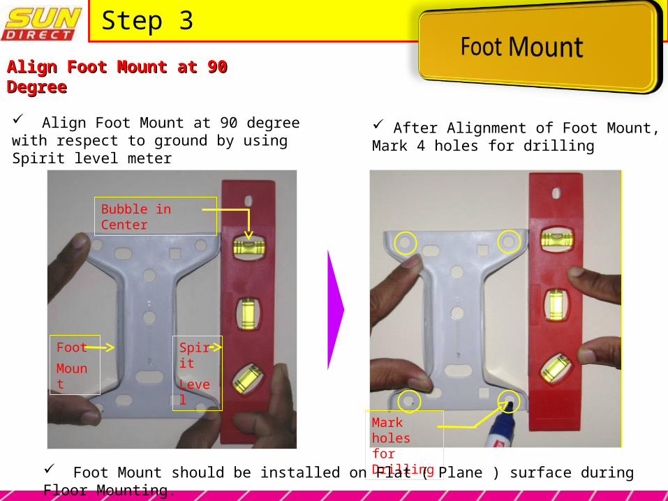
Align Foot Mount at 90 DegreeAlign Foot Mount at 90 Degree
After Alignment of Foot Mount, Mark 4 holes for drilling
Align Foot Mount at 90 degree with respect to ground by using Spirit level meter
Bubble in Center
Foot
Mount
Spirit
Level
Mark holes for Drilling
Foot Mount should be installed on Flat ( Plane ) surface during Floor Mounting.
Step 3
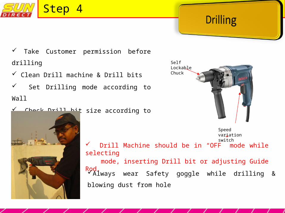
Step 4
Self Lockable Chuck
Speed variation switch
Take Customer permission before drilling
Clean Drill machine & Drill bits
Set Drilling mode according to Wall
Check Drill bit size according to Bolt diameter
Drill Machine should be in “OFF” mode while selecting mode, inserting Drill bit or adjusting Guide Rod.
Always wear Safety goggle while drilling & blowing dust from hole

Step 4
Hold the drill machine with both hands while drilling
Put forwards the left leg ( for a Right handed Person ) with the right index finger on Speed
Control Switch, Hold the handle with Left Hand – vice versa for Left Handed person
Hold the Drill Machine Horizontally &
Drill hole perpendicular to the Wall
Slowly increase the speed by speed
control switch
Safety Precautions : -
Don’t let drill stop while the bit is still inside the hole
(If the drill is stuck in the hole, reverse the direction of rotation & slowly pull out the drill bit)
Don’t change the rotation direction with the switch while the drill machine is ON
Don’t lean on Drill Machine while drilling
Use Drill Machine with Safety Precautions to avoid injury
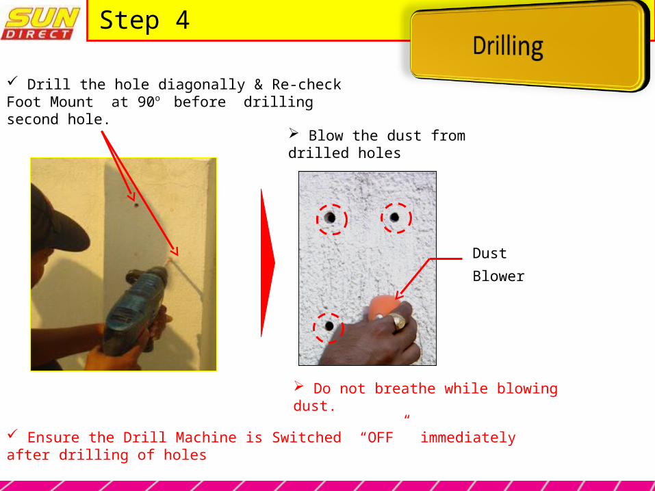
Step 4
Drill the hole diagonally & Re-check Foot Mount at 90o before drilling second hole.
Blow the dust from drilled holes
Do not breathe while blowing dust.
Dust
Blower
Ensure the Drill Machine is Switched “OFF” immediately after drilling of holes
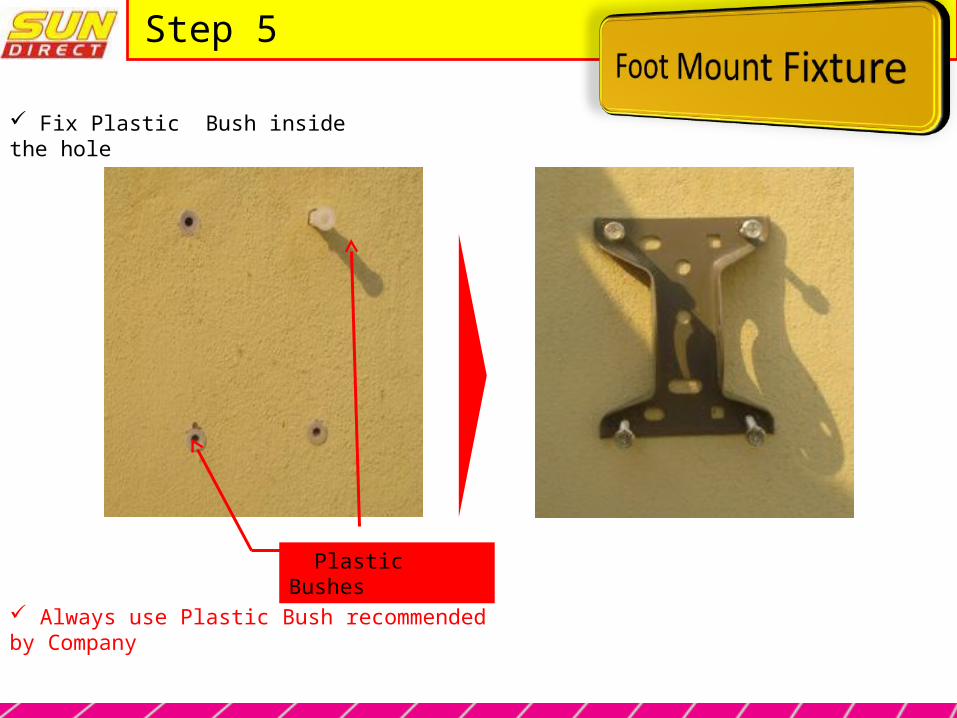
Step 5
Fix Plastic Bush inside the hole
Plastic Bushes
Always use Plastic Bush recommended by Company
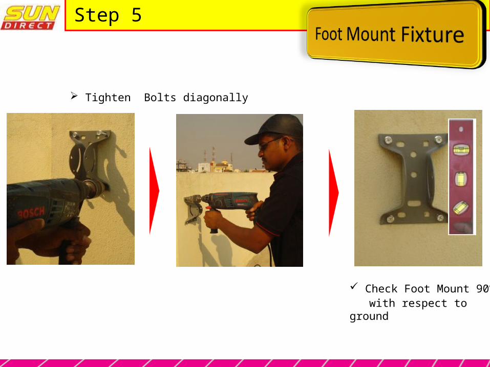
Step 5
Tighten Bolts diagonally
Check Foot Mount 90o
with respect to ground

Step 6
Nuts & Bolts
A B
C
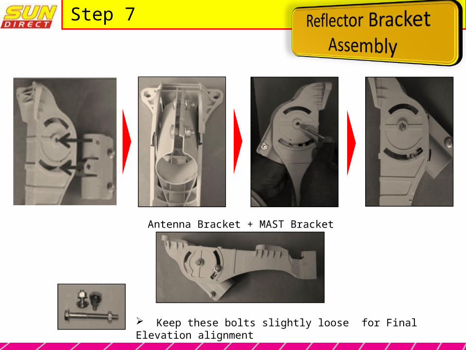
Step 7
Keep these bolts slightly loose for Final Elevation alignment
Antenna Bracket + MAST Bracket
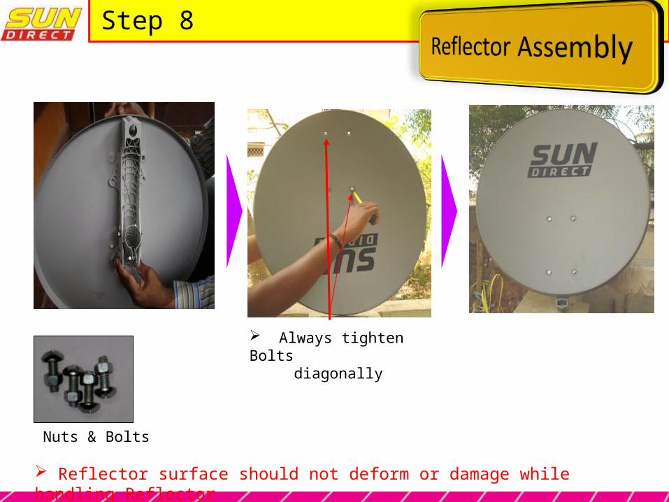
Step 8
Always tighten Bolts diagonally
Reflector surface should not deform or damage while handling Reflector
Nuts & Bolts

Step 9
LNBF + LNBF Clamp
Keep these bolts slightly loose for Final SKEW alignment

Step 10
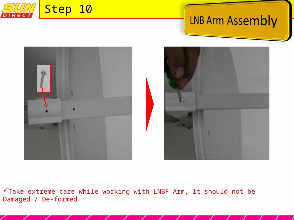
Step 10
Take extreme care while working with LNBF Arm, It should not be Damaged / De-formed

Step 11
Adjust approximate SKEW as per division marking available on LNBF
Clock wise rotation for negative polarisation angle
Rotate LNBF clock wise from LNBF connector for negative (-) Polarisation angle.Rotate LNBF Anti clock wise from LNBF connector for Positive (+) Polarisation angle.
For example : If SKEW angel is “- 23 degree”1 Division = 5 DegreeDivision marking for LNBF rotation = 23 / 5 = 4.6 Align “0” mark of LNBF clamp with approx. 4.6 division (Clockwise) on LNBF.
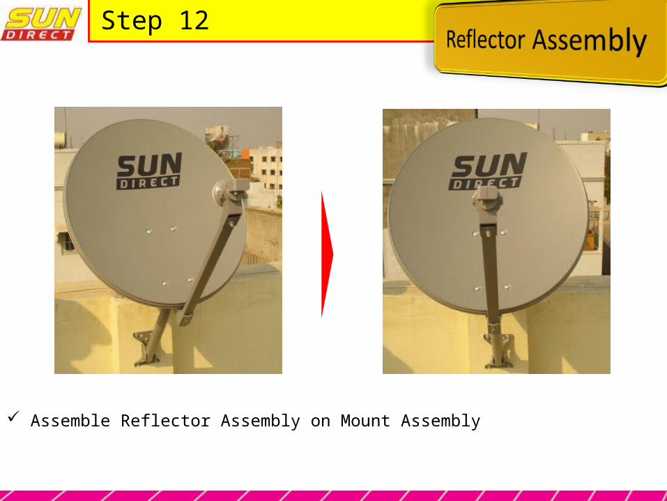
Step 12
Assemble Reflector Assembly on Mount Assembly
Step 12
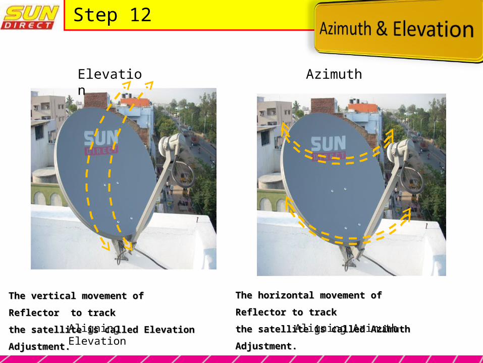
Aligning Elevation Aligning Azimuth
The vertical movement of Reflector to track The vertical movement of Reflector to track
the satellite is called Elevation Adjustment.the satellite is called Elevation Adjustment.
Elevation Azimuth
The horizontal movement of Reflector to track The horizontal movement of Reflector to track
the satellite is called Azimuth Adjustment.the satellite is called Azimuth Adjustment.
Step 13
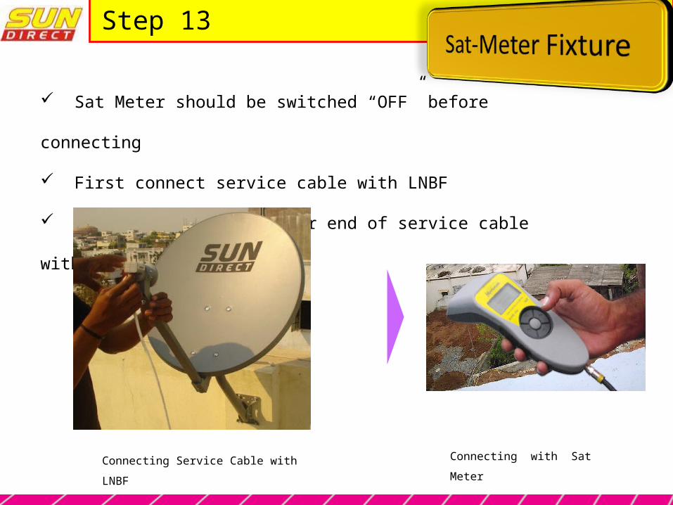
Sat Meter should be switched “OFF” before connecting
First connect service cable with LNBF
After that Connect other end of service cable with Sat Meter
Connecting Service Cable with LNBF Connecting with Sat Meter

Step 14
1-Connect a test cable from LNBF to the hand heldsignal level meter.
2-Swith on the meter confirmthat audio is enabled.
3.Select the desired satelliteon the menu i.e. any of tps of SUN DIRECT TV
5. Approximately try to adjust the azimuth & elevation of the antenna towardsthe direction of the desired satellite, in our case INSAT4B at 93.5degs .
4. A long beep will be heard
Step 14
To counteract Rain fade/ adverse weather condition, Tracking should be done
in such a way to achieve below mentioned parameters for all the Transponders.
MER : More than 12 dB Signal Strength : More than 77dBuV
All the Nut, Bolt & Screws should be properly tightened ( Neither Loose nor Over
tightened ) after Peak Tracking.
The signal Parameters should not change during tightening of Nut, Bolt & Screws

Step 14
After Peak Tracking, Switch “OFF” Sat Meter, remove Service Cable & keep Sat Meter at safe place
After tightening all Nut, Bolt & screws mark the Azimuth & Elevation Adjustment with Permanent marker

Step 15
Tighten all bolts & nuts
Remove the service cable from LNBFconnect the decoder cable - Remember to leave one loop service cable for maintenance.
Now the ODU Now the ODU installation is installation is completecomplete
Use Cable tie