1 belt / 8 disc sander - best woodworking tools - mike's … by delta may result in the risk of...
TRANSCRIPT

INS
TRU
CTIO
NM
AN
UA
L1" Belt / 8" Disc Sander
(Model 31-340)
PART NO. 902120 (0112)Copyright © 2001 Delta Machinery
ESPAÑOL: PÁGINA 19To learn more about DELTA MACHINERY visit our website at: www.deltamachinery.com.For Parts, Service, Warranty or other Assistance,
please call 1-800-223-7278 (In Canada call 1-800-463-3582).
2
GENERAL SAFETY RULESWoodworking can be dangerous if safe and proper operating procedures are not followed. As with all machinery, thereare certain hazards involved with the operation of the product. Using the machine with respect and caution willconsiderably lessen the possibility of personal injury. However, if normal safety precautions are overlooked or ignored,personal injury to the operator may result. Safety equipment such as guards, push sticks, hold-downs, featherboards,goggles, dust masks and hearing protection can reduce your potential for injury. But even the best guard won’t makeup for poor judgment, carelessness or inattention. Always use common sense and exercise caution in the workshop.If a procedure feels dangerous, don’t try it. Figure out an alternative procedure that feels safer. REMEMBER: Yourpersonal safety is your responsibility.
This machine was designed for certain applications only. Delta Machinery strongly recommends that this machine notbe modified and/or used for any application other than that for which it was designed. If you have any questions relativeto a particular application, DO NOT use the machine until you have first contacted Delta to determine if it can or shouldbe performed on the product.
Technical Service ManagerDelta Machinery4825 Highway 45 NorthJackson, TN 38305
(IN CANADA: 505 SOUTHGATE DRIVE, GUELPH, ONTARIO N1H 6M7)
WARNING: FAILURE TO FOLLOW THESE RULES MAY RESULT IN SERIOUS PERSONAL INJURY
1. FOR YOUR OWN SAFETY, READ INSTRUCTIONMANUAL BEFORE OPERATING THE TOOL. Learn thetool’s application and limitations as well as the specifichazards peculiar to it.
2. KEEP GUARDS IN PLACE and in working order.3. ALWAYS WEAR EYE PROTECTION. Wear safety
glasses. Everyday eyeglasses only have impact resistantlenses; they are not safety glasses. Also use face or dustmask if cutting operation is dusty. These safety glassesmust conform to ANSI Z87.1 requirements. NOTE:Approved glasses have Z87 printed or stamped on them.
4. REMOVE ADJUSTING KEYS AND WRENCHES. Formhabit of checking to see that keys and adjusting wrenchesare removed from tool before turning it “on”.
5. KEEP WORK AREA CLEAN. Cluttered areas andbenches invite accidents.
6. DON’T USE IN DANGEROUS ENVIRONMENT. Don’tuse power tools in damp or wet locations, or expose themto rain. Keep work area well-lighted.
7. KEEP CHILDREN AND VISITORS AWAY. All childrenand visitors should be kept a safe distance from work area.
8. MAKE WORKSHOP CHILDPROOF – with padlocks,master switches, or by removing starter keys.
9. DON’T FORCE TOOL. It will do the job better and besafer at the rate for which it was designed.10. USE RIGHT TOOL. Don’t force tool or attachment todo a job for which it was not designed.11. WEAR PROPER APPAREL. No loose clothing, gloves,neckties, rings, bracelets, or other jewelry to get caught inmoving parts. Nonslip footwear is recommended. Wearprotective hair covering to contain long hair.12. SECURE WORK. Use clamps or a vise to hold workwhen practical. It’s safer than using your hand and freesboth hands to operate tool.13. DON’T OVERREACH . Keep proper footing andbalance at all times.14. MAINTAIN TOOLS IN TOP CONDITION. Keep toolssharp and clean for best and safest performance. Followinstructions for lubricating and changing accessories.15. DISCONNECT TOOLS before servicing and whenchanging accessories such as blades, bits, cutters, etc.16. USE RECOMMENDED ACCESSORIES. The use ofaccessories and attachments not recommended by Deltamay cause hazards or risk of injury to persons.17. REDUCE THE RISK OF UNINTENTIONAL STARTING.Make sure switch is in “OFF” position before plugging inpower cord. In the event of a power failure, move switchto the “OFF” position.
18. NEVER STAND ON TOOL. Serious injury could occur ifthe tool is tipped or if the cutting tool is accidentallycontacted.19. CHECK DAMAGED PARTS. Before further use of thetool, a guard or other part that is damaged should becarefully checked to ensure that it will operate properly andperform its intended function – check for alignment ofmoving parts, binding of moving parts, breakage of parts,mounting, and any other conditions that may affect itsoperation. A guard or other part that is damaged should beproperly repaired or replaced.20. DIRECTION OF FEED. Feed work into a blade orcutter against the direction of rotation of the blade or cutteronly.21. NEVER LEAVE TOOL RUNNING UNATTENDED.TURN POWER OFF. Don’t leave tool until it comes to acomplete stop.22. STAY ALERT, WATCH WHAT YOU ARE DOING, ANDUSE COMMON SENSE WHEN OPERATING A POWERTOOL. DO NOT USE TOOL WHILE TIRED OR UNDERTHE INFLUENCE OF DRUGS, ALCOHOL, ORMEDICATION. A moment of inattention while operatingpower tools may result in serious personal injury.23. MAKE SURE TOOL IS DISCONNECTED FROMPOWER SUPPLY whi le motor is be ing mounted,connected or reconnected.24. THE DUST GENERATED by certain woods and woodproducts can be injurious to your health. Always operatemachinery in well ventilated areas and provide for properdust removal. Use wood dust collection systems wheneverpossible.25. WARNING: SOME DUST CREATED BYPOWER SANDING, SAWING, GRINDING, DRILLING,AND OTHER CONSTRUCTION ACTIVITIES containschemicals known to cause cancer, birth defects or otherreproductive harm. Some examples of these chemicalsare:· lead from lead-based paints,· crystalline silica from bricks and cement and other
masonry products, and· arsenic and chromium from chemically-treated lumber. Your risk from these exposures varies, depending on howoften you do this type of work. To reduce your exposureto these chemicals: work in a well ventilated area, andwork with approved safety equipment, such as thosedust masks that are specially designed to filter outmicroscopic particles.
SAVE THESE INSTRUCTIONS. Refer to them often and use them to instruct others.

3
ADDITIONAL SAFETY RULES FORBELT / DISC SANDERS
WARNING: FAILURE TO FOLLOW THESE RULES MAY RESULT IN SERIOUS PERSONAL INJURY.
SAVE THESE INSTRUCTIONS. Refer to them often
and use them to instruct others.
1. DO NOT OPERATE YOUR MACHINE UNTIL IT ISCOMPLETELY ASSEMBLED AND INSTALLED ACCORD-ING TO THE INSTRUCTIONS.
2. THE DUST GENERATED BY CERTAIN WOODS ANDWOOD PRODUCTS CAN BE INJURIOUS TO YOURHEALTH. ALWAYS OPERATE MACHINERY IN WELL-VENTILATED AREAS AND PROVIDE FOR PROPERDUST REMOVAL. USE WOOD DUST COLLECTIONSYSTEMS WHENEVER POSSIBLE.
3. THIS MACHINE CAN BE USED FOR PROCESSINGWOOD AND METAL PRODUCTS; HOWEVER,COMBINING BOTH WOOD DUST AND METAL FILINGSCAN CREATE A FIRE HAZARD. MAKE CERTAIN THATDUST COLLECTOR IS FREE OF WOOD DUST DEPOS-ITS BEFORE PROCESSING METAL PRODUCTS.
4. IF YOU ARE NOT thoroughly familiar with the opera-tion of Belt and Disc Sanders, obtain advice from yoursupervisor, instructor or other qualified person.
5. IF THERE IS ANY TENDENCY for the machine to tipover or move during certain operations such as whensanding long or heavy boards, the machine must besecurely fastened to a supporting surface.
6. MAKE SURE sanding belt runs in the proper direction.Sanding belt must travel down at the front of the machine.
7. MAKE SURE the sanding belt is tracking correctly inorder that it does not run off the pulleys.
8. MAKE SURE the sanding belt or disc is not torn orloose.
9. HOLD the work firmly when sanding.
10. SUPPORT workpiece firmly with the miter gage, back-stop or work table when sanding with the belt. NOTE: Theonly exception is curved work performed on the top wheelof belt.
11. AVOID kickback by sanding in accordance with direc-tional arrows. Sand on downward side of disc. Sanding onthe upward side could cause the workpiece to fly upcausing injury.
12. ALWAYS maintain a maximum clearance of 1/16" orless between the table and the sanding belt or disc.
13. NEVER wear gloves or hold the work with a rag whensanding.
14. SAND with the grain of the work.
15. DO NOT sand pieces of material that are too small tobe safely supported.
16. AVOID awkward hand positions where a sudden slipcould cause a hand to move into the sanding belt or disc.
17. WHEN sanding a large workpiece, provide additionalsupport at table height.
18. NEVER force the work. Slowing or stalling the motorwill cause overheating.
19. WHEN sanding metal move the metal across the beltor disc and cool it when it becomes hot.
20. WHEN sanding metal never use a steady stream ofwater on the workpiece. Dip the workpiece in water to coolit.
21. DO NOT sand or polish magnesium. It could catch onfire.
22. ALWAYS remove scrap pieces and other objects fromthe belt and disc tables before turning the machine “ON.”
23. NEVER perform layout, assembly or set-up work onthe tables while the sander is operating.
24. ALWAYS turn the machine “OFF” and disconnect thecord from the power source before installing or removingaccessories.
25. NEVER leave the machine work area when the poweris “ON” or before the machine has come to a completestop.
26. ALWAYS wear eye protection when operating thesander.
27. THE USE of attachments and accessories not recom-mended by Delta may result in the risk of injuries.
28 SHOULD any part of your sander be missing, dam-aged, or fail in any way, or any electrical components fail toperform properly, shut off switch and remove plug frompower supply outlet. Replace missing, damaged or failedparts before resuming operation.
29. ADDITIONAL INFORMATION regarding the safe andproper operation of this product is available from theNational Safety Council, 1121 Spring Lake Drive, Itasca, IL60143-3201, in the Accident Prevention Manual forIndustrial Operations and also in the Safety Data Sheetsprovided by the NSC. Please also refer to the AmericanNational Standards Institute ANSI 01.1 Safety Require-ments for Woodworking Machinery and the U.S. Depart-ment of Labor OSHA 1910.213 Regulations.

4
POWER CONNECTIONSA separate electrical circuit should be used for your machines. This circuit should not be less than #12 wire and shouldbe protected with a 20 Amp time lag fuse. If an extension cord is used, use only 3-wire extension cords which have 3-prong grounding type plugs and matching receptacle which will accept the machine’s plug. Before connecting themotor to the power line, make sure the switch is in the “OFF” position and be sure that the electric current is of thesame characteristics as indicated on the machine. All line connections should make good contact. Running on lowvoltage will damage the motor.
WARNING: DO NOT EXPOSE THE MACHINE TO RAIN OR OPERATE THE MACHINE IN DAMP LOCATIONS.
MOTOR SPECIFICATIONSYour machine is wired for 120 volt, 60 HZ alternating current. Before connecting the machine to the power source,make sure the switch is in the “OFF” position.
GROUNDING INSTRUCTIONSWARNING: THIS MACHINE MUST BE GROUNDED WHILE IN USE TO PROTECT THE OPERATOR FROMELECTRIC SHOCK.
Fig. A Fig. B
GROUNDED OUTLET BOX
CURRENTCARRYING
PRONGS
GROUNDING BLADEIS LONGEST OF THE 3 BLADES
GROUNDED OUTLET BOX
GROUNDINGMEANS
ADAPTER
2. Grounded, cord-connected machines intended for useon a supply circuit having a nominal rating less than 150volts:
If the machine is intended for use on a circuit that has anoutlet that looks like the one illustrated in Fig. A, themachine will have a grounding plug that looks like the plugillustrated in Fig. A. A temporary adapter, which looks likethe adapter illustrated in Fig. B, may be used to connectthis plug to a matching 2-conductor receptacle as shownin Fig. B if a properly grounded outlet is not available. Thetemporary adapter should be used only until a properlygrounded outlet can be installed by a qualified electrician.The green-colored rigid ear, lug, and the like, extendingfrom the adapter must be connected to a permanentground such as a properly grounded outlet box. Wheneverthe adapter is used, it must be held in place with a metalscrew.
NOTE: In Canada, the use of a temporary adapter is notpermitted by the Canadian Electric Code.
WARNING: IN ALL CASES, MAKE CERTAIN THE RECEPTACLE IN QUESTION IS PROPERLY
GROUNDED. IF YOU ARE NOT SURE HAVE AQUALIFIED ELECTRICIAN CHECK THE RECEPTACLE.
1. All grounded, cord-connected machines:
In the event of a malfunction or breakdown, groundingprovides a path of least resistance for electric current toreduce the risk of electric shock. This machine isequipped with an electric cord having an equipment-grounding conductor and a grounding plug. The plug mustbe plugged into a matching outlet that is properly installedand grounded in accordance with all local codes andordinances.
Do not modify the plug provided - if it will not fit the outlet,have the proper outlet installed by a qualified electrician.
Improper connection of the equipment-groundingconductor can result in risk of electric shock. Theconductor with insulation having an outer surface that isgreen with or without yellow stripes is the equipment-grounding conductor. If repair or replacement of theelectric cord or plug is necessary, do not connect theequipment-grounding conductor to a live terminal.
Check with a qualified electrician or service personnel ifthe grounding instructions are not completely understood,or if in doubt as to whether the machine is properlygrounded.
Use only 3-wire extension cords that have 3-pronggrounding type plugs and matching 3-conductorreceptacles that accept the machine’s plug, as shown inFig. A.
Repair or replace damaged or worn cord immediately.

Use proper extension cords. Make sure your extension cord is in good condition and is a 3-wire extension cordwhich has a 3-prong grounding type plug and matching receptacle which will accept the machine’s plug. Whenusing an extension cord, be sure to use one heavy enough to carry the current of the machine. An undersized cordwill cause a drop in line voltage, resulting in loss of power and overheating. Fig. D, shows the correct gauge to usedepending on the cord length. If in doubt, use the next heavier gauge. The smaller the gauge number, the heavierthe cord.
EXTENSION CORDS
OPERATING INSTRUCTIONSFOREWORD
Delta Model 31-340 is the ultimate workshop machine for wood sanding and metal grinding. The 3000 SFM belt speedis ideal for metal grinding, deburring and sharpening, as well as sanding and buffing jobs. The 8" diameter discoperates at 1725 rpm for finishing hard and soft woods, plastics, compositions and more.
UNPACKING AND CLEANINGCarefully unpack the machine and all loose items from the shipping container(s). Remove the protective coating fromall unpainted surfaces. This coating may be removed with a soft cloth moistened with kerosene (do not use acetone,gasoline or lacquer thinner for this purpose). After cleaning, cover the unpainted surfaces with a good quality householdfloor paste wax.
NOTICE: THE MANUAL COVER PHOTO ILLUSTRATES THE CURRENTPRODUCTION MODEL. ALL OTHER ILLUSTRATIONS ARE REPRESENTATIVE
ONLY AND MAY NOT DEPICT THE ACTUAL COLOR, LABELING ORACCESSORIES.
5
Fig. D
MINIMUM GAUGE EXTENSION CORDRECOMMENDED SIZES FOR USE WITH STATIONARY ELECTRIC MACHINES
Ampere Total Length Gauge ofRating Volts of Cord in Feet Extension Cord
0-6 120 up to 25 18 AWG0-6 120 25-50 16 AWG0-6 120 50-100 16 AWG0-6 120 100-150 14 AWG
6-10 120 up to 25 18 AWG6-10 120 25-50 16 AWG6-10 120 50-100 14 AWG6-10 120 100-150 12 AWG
10-12 120 up to 25 16 AWG10-12 120 25-50 16 AWG10-12 120 50-100 14 AWG10-12 120 100-150 12 AWG
12-16 120 up to 25 14 AWG12-16 120 25-50 12 AWG12-16 120 GREATER THAN 50 FEET NOT RECOMMENDED

6
ASSEMBLY
Fig. 1
Fig. 2
Fig. 3
Fig. 4
ASSEMBLINGBELT UNIT TO BASE1. Place a 10mm lockwasher (D) Fig. 1, and a 10mm flatwasher (E) onto a M10x20mm hex socket head screw (A)and insert the screw up through the hole (B) in the base.Thread the screw into the tapped hole (C) in the bottomof the belt unit, repeat this process for the remaininghole. Do not completely tighten the two screws (A) Fig. 2at this time.
2. Fig. 2, illustrates the two screws (A), inserted into thetwo holes in the bottom of the base.
3. Fig. 3, illustrates the belt unit (D) assembled to thebase.
ASSEMBLING DRIVEBELT AND ADJUSTINGBELT TENSION1. DISCONNECT MACHINE FROM POWER SOURCE.
2. Assemble the drive belt (A) Fig. 4, to the two pulleys,as shown.
3. Slide the belt sander frame assembly (B) Fig. 4,forward until there is approximately 1/4 to 1/2 inch de-flection in the belt (A) at the center span of the pulleysusing light finger pressure.
4. Then tighten the two M10X20mm hex socket headscrews (A) Fig. 2, that fasten the belt unit to the base.
A
BA
D
A B
B
C
D
E
WARNING: FOR YOUR OWN SAFETY, DO NOT CONNECT THE MACHINE TO THE POWER SOURCE UNTILTHE MACHINE IS COMPLETELY ASSEMBLED AND YOU READ AND UNDERSTAND THE ENTIRE INSTRUCTIONMANUAL.
7
Fig. 5
Fig. 6
Fig. 7
Fig. 8
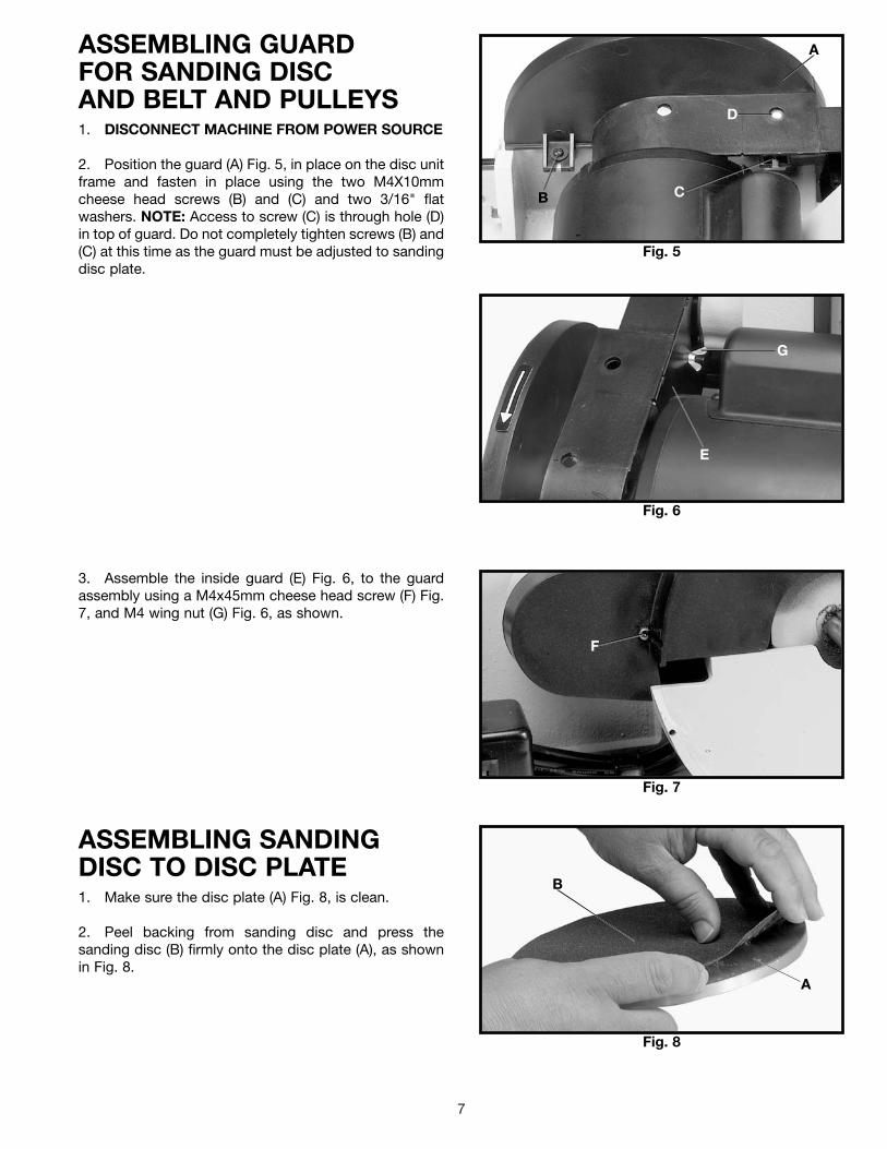
ASSEMBLING GUARDFOR SANDING DISCAND BELT AND PULLEYS1. DISCONNECT MACHINE FROM POWER SOURCE
2. Position the guard (A) Fig. 5, in place on the disc unitframe and fasten in place using the two M4X10mmcheese head screws (B) and (C) and two 3/16" flatwashers. NOTE: Access to screw (C) is through hole (D)in top of guard. Do not completely tighten screws (B) and(C) at this time as the guard must be adjusted to sandingdisc plate.
3. Assemble the inside guard (E) Fig. 6, to the guardassembly using a M4x45mm cheese head screw (F) Fig.7, and M4 wing nut (G) Fig. 6, as shown.
ASSEMBLING SANDINGDISC TO DISC PLATE1. Make sure the disc plate (A) Fig. 8, is clean.
2. Peel backing from sanding disc and press thesanding disc (B) firmly onto the disc plate (A), as shownin Fig. 8.
A
D
CB
E
G
F
B
A

8
Fig. 9
Fig. 10
Fig. 11
Fig. 12
ASSEMBLING SANDING DISCPLATE TO MOTOR SHAFT1. DISCONNECT MACHINE FROM POWER SOURCE.
2. Assemble the sanding disc plate (A) Fig. 9, to themotor shaft with the key (B) in the motor shaft, engagedwith the keyway (C) in the hub of the sanding disc.
3. Rotate the sanding disc until the set screw (D) Fig. 9,is in the up position and tighten set screw (D) Fig. 9,using wrench (E) Fig. 10, through the hole (F) in top ofguard assembly.
4. Adjust the disc guard so that the lip (G) Fig. 10,covers the outer edge of the sanding disc, but not pastthe face of the disc, and tighten the two M4X10mmcheese head screws, one of which is shown at (H), thatattach the disc guard to the base.
ASSEMBLING LOWERSANDING DISC GUARD1. DISCONNECT MACHINE FROM POWER SOURCE.
2. Assemble the lower sanding disc guard (A) to thedisc base using the three M4X6mm sheet metal screwsand washers (B), as shown in Fig. 11.
ASSEMBLING SANDINGDISC DUST CHUTEAssemble the sanding disc dust chute (A) to the discsander base using the M6x15mm cheese head screwand 6.4mm external tooth washer (B), as shown in Fig.12.
D
C
A
B
E
F
H
G
A
B
B
A

9
Fig. 13
Fig. 14
Fig. 15
Fig. 16
ASSEMBLING SANDINGDISC TABLE1. DISCONNECT MACHINE FROM POWER SOURCE.
2. Two clamp handles are supplied with your machine,one for the belt sander table and one for the disc sandertable. Disassemble both handles by unscrewing and re-moving screw (A), spring (B), and handle (C) from lockingstud (D), as shown in Fig. 13.
4. Using locking stud (D) Fig. 13, from handle assembly,and 10mm flat washer (J) Fig. 15, thread locking stud (H)Fig. 15, into threaded hole in base casting to hold tableassembly (E) in place, as shown.
5. Assemble handle (C) Fig. 15, to locking stud (H) andfasten with screw (A) and spring (B).
6. Fig. 16, illustrates the locking handle (C) assembled.NOTE: The locking handle (C) is spring-loaded and canbe repositioned by pulling out the handle andrepositioning it on the serrated stud located underneaththe handle.
3. Position the disc table (E) Fig. 14, on the disc basecasting, making sure the key (F) on the table bracket isengaged with the keyway (G) on the base casting.
A
CD
A
B
CD
F E
G
C
AB
C
H
J
E

10
Fig. 17
Fig. 18
ASSEMBLING BELTSANDER TABLE1. DISCONNECT MACHINE FROM POWER SOURCE.
2. Position the table assembly (A) Fig. 17, in position onthe belt sander frame and using locking stud (B), fromhandle assembly, and flat washer (C), thread locking stud(B) into threaded hole in casting to hold table assemblyin place, as shown.
3. Assemble handle (D) Fig. 18, to locking stud andfasten with screw (E) and spring.
4. NOTE: The locking handle (D) Fig. 18, is spring-loaded and can be repositioned by pulling out the handleand repositioning it on the serrated stud locatedunderneath the handle.
A
BC
FASTENING SANDER TO SUPPORTING SURFACEIF DURING OPERATION THERE IS ANY TENDENCY FOR THE SANDER TO TIP OVER, SLIDE OR WALK ON THESUPPORTING SURFACE, THE SANDER MUST BE SECURED TO THE SUPPORTING SURFACE. TWO HOLESARE SUPPLIED IN THE SANDER BASE PLATE FOR MOUNTING.
OPERATING CONTROLS AND ADJUSTMENTS
STARTING ANDSTOPPING SANDERThe switch (A) Fig. 21, is mounted in a switch box on thesander base. To turn the sander “ON” move the switch(A) to the right position. To turn the sander “OFF” movethe switch (A) to the left position.
Fig. 21
Fig. 22
LOCKING SWITCH INTHE “OFF” POSITIONIMPORTANT: When the machine is not in use, the switchshould be locked in the “OFF” position to preventunauthorized use. This can be done by grasping theswitch toggle (B) and pulling it out of the switch, asshown in Fig. 22. With the switch toggle (B) removed, theswitch will not operate. However, should the switchtoggle be removed while the sander is running, it can beturned “OFF” once, but cannot be restarted withoutinserting the switch toggle (B).
A
B
E
D

11
Fig. 23
TRACKING THESANDING BELTThe belt tracking adjustment is set at the factory so thatthe belt (A) Fig. 23, will run true on the pulleys. If,however, the belt (A) should lead to one side or the otheron the pulleys, an adjustment can be made by turningthe tracking knob (B). Turning the knob (B) clockwise willmove the belt to the right when facing the sander.Turning the knob (B) counterclockwise will move the beltto the left. THIS ADJUSTMENT IS USUALLY VERYSLIGHT.
Fig. 24
Fig. 25
Fig. 26
PLATENThe platen (A) Fig. 24, is constructed of heavy steel toproperly support the work when sanding. The platenshould be adjusted so it is almost touching the back ofthe sanding belt. To adjust the platen, loosen screw (B),adjust the platen to the desired position and tightenscrew (B).
To remove the platen for operations such as strapping,contour sanding, polishing, or other special operations,remove screw (B) Fig. 24, and remove platen (A).
BELT TABLE ADJUSTMENTSThe belt sander table (A) Fig. 25, can be tilted or movedin or out by loosening lock handle (B), moving the tableto the desired position, and tightening lock handle (B).NOTE: The lock handle (B) is spring-loaded and can berepositioned by pulling out on the handle andrepositioning it on the serrated locking stud locateddirectly under the handle.
WARNING: TO AVOID TRAPPING THE WORK ORFINGERS BETWEEN THE TABLE AND SANDINGBELT, THE TABLE EDGE (C) FIG. 25, SHOULD BE PO-SITIONED A MAXIMUM OF 1/16 INCH FROMSANDING BELT (D) AS SHOWN.
For most sanding operations the table is set at a 90degree angle to the sanding belt. A positive stop isprovided to insure fast positioning of the table at 90degrees to the belt. Loosen the table lock lever (B) Fig.26, and tilt the table to the rear as far as possible. Usinga combination square (E), place one end of the square onthe table with the other end against the sanding belt, asshown, and check to see if the table is 90 degrees to thebelt. If the table is not at 90 degrees to the belt, turnadjusting screw with wrench (F). The adjusting screwshould bottom against the frame when the table is 90degrees to the belt.
A
B
A
B
B
A
C
D
F
E
B
12
Fig. 27
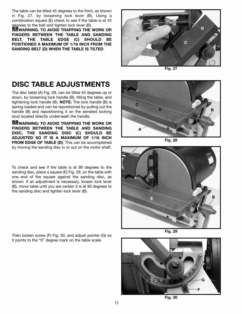
The table can be tilted 45 degrees to the front, as shownin Fig. 27, by loosening lock lever (B). Using acombination square (E) check to see if the table is at 45degrees to the belt and tighten lock lever (B).
WARNING: TO AVOID TRAPPING THE WORK ORFINGERS BETWEEN THE TABLE AND SANDINGBELT, THE TABLE EDGE (C) SHOULD BEPOSITIONED A MAXIMUM OF 1/16 INCH FROM THESANDING BELT (D) WHEN THE TABLE IS TILTED.
DISC TABLE ADJUSTMENTSThe disc table (A) Fig. 28, can be tilted 45 degrees up ordown, by loosening lock handle (B), tilting the table, andtightening lock handle (B). NOTE: The lock handle (B) isspring-loaded and can be repositioned by pulling out thehandle (B) and repositioning it on the serrated lockingstud located directly underneath the handle.
WARNING: TO AVOID TRAPPING THE WORK ORFINGERS BETWEEN THE TABLE AND SANDINGDISC, THE SANDING DISC (C) SHOULD BEADJUSTED SO IT IS A MAXIMUM OF 1/16 INCHFROM EDGE OF TABLE (D). This can be accomplishedby moving the sanding disc in or out on the motor shaft.
To check and see if the table is at 90 degrees to thesanding disc, place a square (E) Fig. 29, on the table withone end of the square against the sanding disc, asshown. If an adjustment is necessary, loosen lock lever(B), move table until you are certain it is at 90 degrees tothe sanding disc and tighten lock lever (B).
Then loosen screw (F) Fig. 30, and adjust pointer (G) soit points to the “0” degree mark on the table scale.
Fig. 28
Fig. 29
Fig. 30
E
D
C
E B
G
F
BDC
A

13
Fig. 31
Fig. 32
REMOVING ANDINSTALLINGABRASIVE BELTS1. DISCONNECT MACHINE FROM POWER SOURCE.
2. Unscrew and remove the two knobs (A) Fig. 31, andremove the side cover (B) from the belt unit.
3. Press down on the tracking knob to release belttension and remove belt (C) Fig. 32, from the threepulleys (D), as shown.
4. Install new 1" x 42" belt and replace side cover.Check belt tracking by referring to the section“TRACKING THE SANDING BELT,” and adjust ifnecessary. IMPORTANT: Some belts have a directionalarrow printed on the inside of the belt. In these cases thebelt must be installed so the directional arrow is in thesame direction that the machine is running. The sandingbelt travels down at the front of the machine.
REMOVING ANDINSTALLING ABRASIVEDISCS1. DISCONNECT MACHINE FROM POWER SOURCE.2. Remove the sanding disc table.3. Remove the old abrasive disc by peeling it from thesanding disc plate.4. Clean the disc plate thoroughly.5. Remove the backing from the new abrasive disc andpress the abrasive disc firmly onto the disc plate.6. Replace the sanding disc table.
Fig. 33
Fig. 34
MITER GAGEA miter gage (A) Fig. 33, is supplied with your sander andcan be used on the disc table, as shown, or on the belttable. The miter gage can be set anywhere up to 45degrees right or left by loosening lock knob (B), tiltingmiter gage body (C) to the desired angle and tighteninglock knob (B).
DUST CHUTESTwo dust chutes are supplied with your belt and discsander and are equipped with 1-1/4 inch I.D. openingsthat can easily be connected to a dust collection system.Dust chute (A) Fig. 34, is for the belt unit and dust chute(B) is for the disc unit.
B
A
A
D
D
C
C
A
B
AB

14
TYPICAL OPERATIONSWARNING: THE USE OF ATTACHMENTS AND
ACCESSORIES NOT RECOMMENDED BY DELTAMAY RESULT IN RISK OF INJURIES.The following are just some of the many operations thatcan be performed with your Delta 1" Belt/8" Disc Sander.
Sharpening a cold chisel on the belt unit with the tabletilted.
Fig. 35
Fig. 36
Sanding aluminum on the disc unit with the table tiltedand using the miter gage as a guide. NOTE: Always sandon the left (downward) side of the sanding disc, asshown. Sanding on the right (upward) side of the sandingdisc could cause the workpiece to fly up, which could behazardous.
Fig. 37
Fig. 38
Sharpening a wood chisel on the belt unit using a blockof wood to support the chisel and provide clearance forthe chisel handle.
Sanding outside curves on the belt unit with the platen.

15
Fig. 39
Fig. 40
Fig. 41
Polishing using the Delta accessory Felt Belt in place ofthe sanding belt.
Sanding in tight areas with the sanding belt.
Inside curves can be sanded on the top sanding wheelwith the side cover removed.

16
Two Year Limited WarrantyDelta will repair or replace, at its expense and at its option, any Delta machine, machine part, or machine accessory whichin normal use has proven to be defective in workmanship or material, provided that the customer returns the productprepaid to a Delta factory service center or authorized service station with proof of purchase of the product within twoyears and provides Delta with reasonable opportunity to verify the alleged defect by inspection. Delta may require thatelectric motors be returned prepaid to a motor manufacturer’s authorized station for inspection and repair or replacement.Delta will not be responsible for any asserted defect which has resulted from normal wear, misuse, abuse or repair oralteration made or specifically authorized by anyone other than an authorized Delta service facility or representative. Underno circumstances will Delta be liable for incidental or consequential damages resulting from defective products. Thiswarranty is Delta’s sole warranty and sets forth the customer’s exclusive remedy, with respect to defective products; allother warranties, express or implied, whether of merchantability, fitness for purpose, or otherwise, are expresslydisclaimed by Delta.
Printed in U.S.A.
PARTS, SERVICE OR WARRANTY ASSISTANCEAll Delta Machines and accessories are manufactured to high quality standards and are serviced by a networkof Porter-Cable • Delta Factory Service Centers and Delta Authorized Service Stations. To obtain additionalinformation regarding your Delta quality product or to obtain parts, service, warranty assistance, or the locationof the nearest service outlet, please call 1-800-223-7278 (In Canada call 1-800-463-3582).
ACCESSORIESA complete line of accessories is available from your Delta Supplier, Porter-Cable • Delta Factory Service Centers,and Delta Authorized Service Stations. Please visit our Web Site www.deltamachinery.com for a catalog orfor the name of your nearest supplier.
WARNING: Since accessories other than those offered by Delta have not been tested with this product, use of such accessories could be hazardous. For safest operation, only Delta recommended accessories should be used with this product.

17
NOTES

18
NOTES